Embed Size (px)
Citation preview

International Journal of Science and Research (IJSR) ISSN (Online): 2319-7064
Index Copernicus Value (2013): 6.14 | Impact Factor (2015): 6.391
Volume 5 Issue 8, August 2016 www.ijsr.net
Licensed Under Creative Commons Attribution CC BY
Real-Time Climate Control and Remote Monitoring of Polyhouse based on LabVIEW
Janet Joseph1, Nitha M Biju2
1 PG Scholar, MG University, St. Joseph’s College of Engineering and Technology (SJCET), Palai, Choondachery-686579, Kottayam, Kerala, India
2 Assistant Professor, MG University, St. Joseph’s College of Engineering and Technology (SJCET), Palai, Choondachery-686579, Kottayam, Kerala, India
Abstract: This paper discuss about the design and development of a low cost system that can monitor and control the environmental parameters inside a polyhouse. The ultimate aim of this paper is to motivate organic farming in everyone's life even in their busy schedules. So no matter where we go the entire polyhouse can be controlled and monitored by remote devices like smart phones or Personal Computers (PC) at any remote locations. The design of farmer friendly software is developed based on LabVIEW which gives complete Graphical User Interface (GUI) of the farm in e- gadgets such as laptop or smart phones. The LabVIEW software is installed in the computer. In the proposed system, online automation of the polyhouse is made possible by means of Internet. In addition, live video streaming of the polyhouse, located at remote places are captured. This leads to complete elimination of labour power. Appropriate environmental conditions are necessary for optimum plant growth, improved crop yields and good productivity. Hence the real- time climatic parameters are measured and controlled with different sensors and actuators by the computer. The computer reads and controls the climatic parameters by Data Acquisition (DAQ). PC-based DAQ systems exploit the processing power, productivity, display and connectivity capabilities of computers. Existing systems are bulky, costly and difficult to maintain. In the proposed system, the bulky and costly DAQ instrument is replaced by a low cost, specially designed microcontroller based DAQ card.
Keywords: LabVIEW, DAQ, Android phone, Polyhouse automation, Online automation
1. Introduction Polyhouse farming is very relevant for encouraging organic farming. The implementation of polyhouse in our houses, offices, institutions etc. can cultivate crops in a closed and secured environment. Hence the dangerous usage of pesticides which lead to many deadly diseases can be avoided or minimized. Polyhouse farming can be done without depending on natural phenomena like rainfall so that production of crops can be increased. Since polyhouse is a closed environment, polyhouse automation of climatic parameters is established to acquire optimum level of climate in order to improve crop yield, growth and production. Nowadays, all are busy with their schedules. No one have time to look after their polyhouse garden. No matter whatever busy schedules we are in, we never forgets to use our e-gadgets. Mobile phones have become the part and parcel of life. For this reason, in this paper, the polyhouse can be monitored and controlled by using the applications in remote devices like smartphones, laptops, PC and through Internet applications. This system consists of various sensors, namely soil moisture, temperature, relative humidity and light sensors. The LabVIEW software is installed in the computer and all the sensors and actuators communicates with the computer by the process of Data Acquisition (DAQ). The DAQ instruments in existing systems are very expensive [1]. Hence, in this paper a low cost microcontroller can be used as a DAQ card. Vision acquisition is also made possible so that the polyhouse farm can be physically monitored from any part of the world.
2. Block Diagram
The block diagram of the proposed system is shown in fig. 2.1, consists of different modules which are interfaced to the computer. The 12V, 5A DC input power is regulated to 5V DC by a voltage regulator IC 7805. In this system mainly five types of sensor modules are used and they are integrated to a DAQ instrument. In the proposed system, ATMEGA 328 IC acts as DAQ card. This DAQ card is connected to the computer by UART to provide serial communication. There are temperature sensor, light sensor, humidity sensor, soil moisture sensor and gas sensor. The actuators used for controlling the parameters temperature, light, soil moisture, gas and humidity are heater, fan, grow light or artificial light, water pump, sprayer etc. The actuators are triggered by relay unit and actuator driving unit. The sensor block and actuator block communicates with the computer through DAQ card. The fig. 2.1 shows two DAQs, one is to read the sensor values from each sensors and the other is used to control the actuators. A web camera is connected to the computer so as to capture live video of the polyhouse farm. An android phone is interfaced with the embedded board by web based communication protocol or by using Wi-Fi. The sensor readings and the control of actuators are accessed by remote devices like mobile phones and other PC etc. In this system a web publishing tool is also used so that all the access and control of polyhouse is available in internet through IP (Internet Protocol) address. Therefore, the polyhouse can be controlled and monitored from any part of the world and even visual monitoring is possible through any web browser with internet.
Paper ID: ART20161295 1665

International Journal of Science and Research (IJSR) ISSN (Online): 2319-7064
Index Copernicus Value (2013): 6.14 | Impact Factor (2015): 6.391
Volume 5 Issue 8, August 2016 www.ijsr.net
Licensed Under Creative Commons Attribution CC BY
Figure 2.1: Block Diagram of Proposed System
3. System Operation
The proposed system is a real-time system that can monitor and control the weather inside a polyhouse at low cost. The polyhouse can be accessed and controlled by using PC and with an android phone which are capable of performing the following operations.
1. Polyhouse Monitoring System2. Polyhouse Alert System3. Polyhouse Automation System4. Visual Monitoring of the Polyhouse5. Polyhouse Online Control and Monitoring through Internet
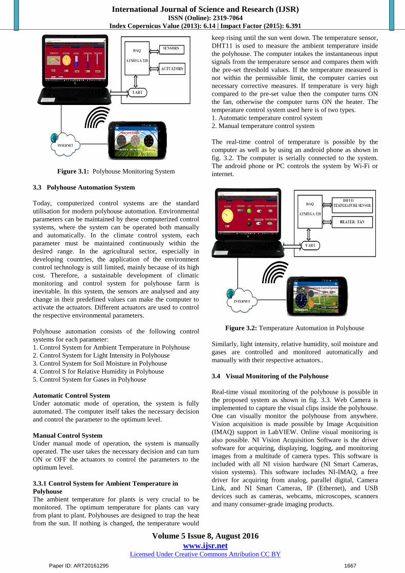
3.1 Polyhouse Monitoring System
The most essential parameters to grow crops for good yield and optimum production are light intensity, ambient temperature, soil temperature, humidity, soil moisture and gas. Under this section, it mainly includes the reading of all the sensor values at real-time. The fig.3.1 shows the real-time monitoring using the computer as well as using an android phone. The android phone can control or monitor the system either by Wi-Fi or using Internet. Hence the values of the parameters are monitored in real-time.
3.2 Polyhouse Alert System
The sensor values read by the sensors are sent to the computer through DAQ microcontroller, ATMEGA 328. The computer analyses and compares the input signals from each sensor with the predefined threshold values of each parameter. If any variation from the pre-defined values occurs, then the computer gives some alert signal by means of LED or buzzer. With this module, you can start monitoring each parameter and if it surpasses a threshold, it can illuminate a virtual LED in NI LabVIEW software. It can also cause the system to issue an audible tone.
Paper ID: ART20161295 1666
International Journal of Science and Research (IJSR) ISSN (Online): 2319-7064
Index Copernicus Value (2013): 6.14 | Impact Factor (2015): 6.391
Volume 5 Issue 8, August 2016 www.ijsr.net
Licensed Under Creative Commons Attribution CC BY
Figure 3.1: Polyhouse Monitoring System
3.3 Polyhouse Automation System
Today, computerized control systems are the standard utilisation for modern polyhouse automation. Environmental parameters can be maintained by these computerized control systems, where the system can be operated both manually and automatically. In the climate control system, each parameter must be maintained continuously within the desired range. In the agricultural sector, especially in developing countries, the application of the environment control technology is still limited, mainly because of its high cost. Therefore, a sustainable development of climatic monitoring and control system for polyhouse farm is inevitable. In this system, the sensors are analysed and any change in their predefined values can make the computer to activate the actuators. Different actuators are used to control the respective environmental parameters.
Polyhouse automation consists of the following control systems for each parameter: 1. Control System for Ambient Temperature in Polyhouse 2. Control System for Light Intensity in Polyhouse 3. Control System for Soil Moisture in Polyhouse 4. Control S for Relative Humidity in Polyhouse 5. Control System for Gases in Polyhouse
Automatic Control System Under automatic mode of operation, the system is fully automated. The computer itself takes the necessary decision and control the parameter to the optimum level.
Manual Control System Under manual mode of operation, the system is manually operated. The user takes the necessary decision and can turn ON or OFF the actuators to control the parameters to the optimum level.
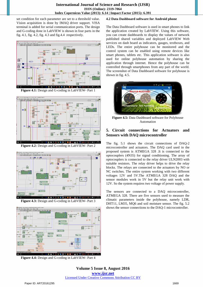
3.3.1 Control System for Ambient Temperature in Polyhouse The ambient temperature for plants is very crucial to be monitored. The optimum temperature for plants can vary from plant to plant. Polyhouses are designed to trap the heat from the sun. If nothing is changed, the temperature would
keep rising until the sun went down. The temperature sensor, DHT11 is used to measure the ambient temperature inside the polyhouse. The computer intakes the instantaneous input signals from the temperature sensor and compares them with the pre-set threshold values. If the temperature measured is not within the permissible limit, the computer carries out necessary corrective measures. If temperature is very high compared to the pre-set value then the computer turns ON the fan, otherwise the computer turns ON the heater. The temperature control system used here is of two types. 1. Automatic temperature control system 2. Manual temperature control system
The real-time control of temperature is possible by the computer as well as by using an android phone as shown in fig. 3.2. The computer is serially connected to the system. The android phone or PC controls the system by Wi-Fi or internet.
Figure 3.2: Temperature Automation in Polyhouse
Similarly, light intensity, relative humidity, soil moisture and gases are controlled and monitored automatically and manually with their respective actuators..
3.4 Visual Monitoring of the Polyhouse
Real-time visual monitoring of the polyhouse is possible in the proposed system as shown in fig. 3.3. Web Camera is implemented to capture the visual clips inside the polyhouse. One can visually monitor the polyhouse from anywhere. Vision acquisition is made possible by Image Acquisition (IMAQ) support in LabVIEW. Online visual monitoring is also possible. NI Vision Acquisition Software is the driver software for acquiring, displaying, logging, and monitoring images from a multitude of camera types. This software is included with all NI vision hardware (NI Smart Cameras, vision systems). This software includes NI-IMAQ, a free driver for acquiring from analog, parallel digital, Camera Link, and NI Smart Cameras, IP (Ethernet), and USB devices such as cameras, webcams, microscopes, scanners and many consumer-grade imaging products.
Paper ID: ART20161295 1667

International Journal of Science and Research (IJSR) ISSN (Online): 2319-7064
Index Copernicus Value (2013): 6.14 | Impact Factor (2015): 6.391
Volume 5 Issue 8, August 2016 www.ijsr.net
Licensed Under Creative Commons Attribution CC BY
Figure 3.3: Visual Monitoring of the Polyhouse
3.5 Polyhouse Online Control and Monitoring through
The complete online based application is designed to perform the following major tasks: (i) Publishing Data (ii) Sharing Data (iii) Remote Control (iv) Distributed Execution
The above tasks are achieved with the hardware architecture, executed and controlled by software support in LabVIEW environment. With the built-in web server in LabVIEW, the front panel of the application can be published. Once the web server is enabled, LabVIEW generates front panel images that can be accessed from any web browser. The web page is created by the web publishing tool in LabVIEW. By using shared variables shown in the fig. 3.4, the parameters like temperature, relative humidity, light intensity, soil moisture are shared as global variables across net. Hence, the user can read or write these variables from any web browser. Also, the user can control and monitor the polyhouse from any part of the world. Since, visual monitoring is possible, by image acquisition, the live video clips of polyhouse can be seen through online. Hence, one can monitor the polyhouse anywhere from the world. The VI (Virtual Instrument of LabVIEW) can be connected to the Internet using the web publishing tool in LabVIEW software. The dialog box of web publishing tool is shown in fig.3.5. The viewing mode is selected as the embedded so the front panel of the VI can be viewed and controlled by the user via Internet. The desired title and caption for thewebpage is to be given by the operator. Finally, the web server view is given to connect to the Internet. The URL address of the web page published is used by the client to control and monitor the climatic parameters inside the polyhouse. The user can operate the system at anywhere through a web browser.
Figure 3.4: Shared Variables in LabVIEW
Figure 3.5: Dialog box of Web Publishing tool in LabVIEW
4. Software Description
Embedded software is computer software, written to control machines or devices. It is typically specialized for the particular hardware that it runs on and has time and memoryconstraints. The software part of the proposed system mainly includes the system software and application software. Both are run on hardware layer. The system software used can be the OS of the computer particularly windows 10.The application softwares used are NI LabVIEW 2013, NI Data Dashboard 2.2.
4.1 Design of the system in NI LabVIEW 2013
LabVIEW is the short of Laboratory Virtual Instrument Engineering Workbench; it is a product of National Instruments (NI). The NI LabVIEW 2013 is installed in the computer. The entire system is designed in LabVIEW software. The program coding is called graphical coding or G- coding. The designing of the sensor block and actuator block is done in the block diagram. The control systems are designed with appropriate threshold values. Design of pre-
Paper ID: ART20161295 1668
International Journal of Science and Research (IJSR) ISSN (Online): 2319-7064
Index Copernicus Value (2013): 6.14 | Impact Factor (2015): 6.391
Volume 5 Issue 8, August 2016 www.ijsr.net
Licensed Under Creative Commons Attribution CC BY
set condition for each parameter are set to a threshold value. Vision acquisition is done by IMAQ driver support. VISA terminal is added for serial communication ports. The design and G-coding done in LabVIEW is shown in four parts in the fig. 4.1, fig. 4.2, fig. 4.3 and fig.4.4 respectively.
Figure 4.1: Design and G-coding in LabVIEW- Part 1
Figure 4.2: Design and G-coding in LabVIEW- Part 2
Figure 4.3: Design and G-coding in LabVIEW- Part 3
Figure 4.4: Design and G-coding in LabVIEW- Part 4
4.2 Data Dashboard software for Android phone
The Data Dashboard software is used in smart phones to link the application created by LabVIEW. Using this software,you can create dashboards to display the values of network published shared variables and deployed LabVIEW Web services on dash board as indicators, gauges, textboxes, and LEDs. The entire polyhouse can be monitored and the control system can be enabled using remote devices like smart phones, tablets etc. This application software is also used for online polyhouse automation by sharing the application through internet. Hence the polyhouse can be controlled through smartphones from any part of the world. The screenshot of Data Dashboard software for polyhouse is shown in fig. 4.5.
Figure 4.5: Data Dashboard software for Polyhouse Automation
5. Circuit connections for Actuators and Sensors with DAQ microcontroller
The fig. 5.1 shows the circuit connections of DAQ-2microcontroller and actuators. The DAQ card used in the proposed system is ATMEGA 328 .It is connected to the optocouplers (4N35) for signal conditioning. The array of optocouplers is connected to the relay driver ULN2003 withsuitable resistors. The relay driver helps to drive the relay blocks. The relays are connected to the actuators by NO or NC switches. The entire system working with two different voltages 12V and 5V.The ATMEGA 328 DAQ and the sensor modules work in 5V but the relay unit work with 12V. So the system requires two voltage of power supply.
The sensors are connected to a DAQ microcontroller,ATMEGA 328. There are five sensors used to measure the climatic parameters inside the polyhouse, namely LDR, DHT11, LM35, MQ6 and soil moisture sensor. The fig. 5.2shows the sensor connections to the DAQ-1 microcontroller.
Paper ID: ART20161295 1669

International Journal of Science and Research (IJSR) ISSN (Online): 2319-7064
Index Copernicus Value (2013): 6.14 | Impact Factor (2015): 6.391
Volume 5 Issue 8, August 2016 www.ijsr.net
Licensed Under Creative Commons Attribution CC BY
Figure 5.1 : Circuit connections for Actuators with DAQ microcontroller
The available battery power is 12v 5A stable DC. The input power is step down to 5v DC from 12v DC power line by the power supply unit and with the help of IC7805.
Figure 5.2: Sensor connections with DAQ -1microcontroller
6. Hardware Implementation
The fig. 6.1 shows the hardware implementation of the proposed system as prototype. The entire system is working with two different voltages, 12v and 5v. The microcontroller and the sensor modules are working with 5v and the relay unit is working with 12v. The power supply of 12V battery is step down to 5V by using 7805 regulator. In the proposed system the sensors are connected to the computer through DAQ-1 and the actuators are connected to the computer through DAQ-2. The microcontroller, ATMEGA 328 is used as DAQ card. The DAQs are connected to the computer by serial communication using UART. LabVIEW software is installed in the computer and coding is done. A LAN network is created and the polyhouse system can be controlled and monitored by remote devices like PC or android phones with Wi-Fi. Online monitoring and control of the polyhouse is done by any web browsers using internet. This is made possible by publishing a web page and with the shared variables, all the access and control of the entire
system is established. By online facilities, the polyhouse can be controlled and monitored from any part of the world. In addition, a web cam is implemented to visually monitor the polyhouse farm. Vision acquisition is also established by online, so that the owner can visually monitor the polyhouse from any part of the world.
Figure 6.1: Hardware Implementation of Proposed System as Prototype
7. Result
7.1 Real-Time implementation of Proposed System inPolyhouse by LabView
This shows the result of all the following,,done using LabVIEW in the computer1. Real-time Monitoring of Parameters2. Temperature Automation3. Light intensity Automation4. Soil Moisture Automation5. Gas Automation6. Relative Humidity Automation
7.1.1 Real-time Monitoring of Parameters
The sensor values are measured and monitored in real-time. Parameters such as ambient temperature, light intensity,relative humidity, gases and soil moisture inside the polyhouse are measured, analysed, controlled and monitored. The fig. 7.1 shows the screen-shot of real-time monitoring of parameters on LabVIEW.
7.1.2 Temperature AutomationTemperature is controlled by heater and cooling fan. The control system can be automatic or manual mode. The fig.7.2 shows the screen-shot of temperature automation on LabVIEW.
Paper ID: ART20161295 1670

International Journal of Science and Research (IJSR) ISSN (Online): 2319-7064
Index Copernicus Value (2013): 6.14 | Impact Factor (2015): 6.391
Volume 5 Issue 8, August 2016 www.ijsr.net
Licensed Under Creative Commons Attribution CC BY
Figure 7.1: Real-time Monitoring of Parameters on LabVIEW
Figure 7.2: Temperature Automation on LabVIEW
7.1.3 Light intensity AutomationLight intensity is controlled by grow light. The control system can be automatic or manual mode. The fig. 7.3 shows the screen-shot of light automation on LabVIEW.
Figure 7.3: Light intensity Automation on LabVIEW
7.1.4 Soil Moisture AutomationSoil moisture is controlled by water pump. The control system can be automatic or manual mode. The fig.7.4 shows the screen-shot of soil moisture automation on LabVIEW.
7.1.5 Gas AutomationGas is controlled by fan. The control system can be automatic or manual mode. The fig.7.5 shows the screen-shot of gas automation on LabVIEW.
Figure 7.4: Soil Moisture Automation on LabVIEW
Figure 7.5: Gas Automation on LabVIEW
7.1.6 Relative Humidity AutomationRelative humidity is controlled by heater. The control system can be automatic or manual mode. The fig.7.6 shows the screen-shot of relative humidity automation on LabVIEW.
Figure 7.6: Relative Humidity Automation on LabVIEW
7.2 Automation of Polyhouse by using Android Phone
An android phone is used to control and monitor the polyhouse located at remote areas. The Data Dashboard software is installed in the android phone. The sensor readings and the control system for each parameter are made possible by using android phone.
7.2.1 Sensor Readings with Android PhoneThe readings of each parameter are displayed on android phone using Data Dashboard software. This can be monitored at real-time. The fig.7.7 shows the screen-shot of sensor readings by using an android phone.
Paper ID: ART20161295 1671

International Journal of Science and Research (IJSR) ISSN (Online): 2319-7064
Index Copernicus Value (2013): 6.14 | Impact Factor (2015): 6.391
Volume 5 Issue 8, August 2016 www.ijsr.net
Licensed Under Creative Commons Attribution CC BY
Figure 7.7: Sensor Readings with Android Phone
7.2.2 Temperature Automation with Android PhoneThe temperature can be controlled by using android phone. It can control the temperature by actuating the heater or cooling fan. Temperature automation can be automatic or manual mode. The fig.7.8 shows the screen-shot of temperature automation with android phone.
Figure 7.8: Temperature Automation with Android Ph one
7.2.3 Light Intensity Automation with Android PhoneThe light intensity can be controlled by using android phone. It can actuate the grow light. Light automation can be automatic or manual mode. The fig.7.9 shows the screen-shot of light intensity automation by using android phone.
Figure 7.9: Light Intensity Automation with Android Phone
7.2.4 Soil Moisture Automation with Android PhoneThe soil moisture can be controlled by using android phone. It can control the moisture by actuating the water pump. Soil moisture automation can be automatic or manual mode. The
fig. 7.10 shows the screen-shot of soil moisture automation by using android phone.
Figure 7.10: Soil Moisture Automation with Android Phone
7.2.5 Gas Automation with Android PhoneThe gas can be controlled by using android phone. It can control the gases by actuating the fan. Gas automation can be automatic or manual mode. The fig. 7.11 shows the screen-shot of gas automation by using android phone.
Figure 7.11: Gas Automation with Android Phone
7.2.6 Relative Humidity Automation with Android PhoneThe Relative Humidity can be controlled by using android phone. It can control the humidity by actuating the heater. Relative Humidity automation can be automatic or manual mode. The fig. 7.12 shows the screen-shot of relative humidity automation by using android phone.
Figure 7.12: Relative Humidity Automation with Android Phone
7.3 Online Control and Monitoring of Polyhouse
Once the web server is enabled, LabVIEW generates front panel images that can be accessed from any web browser.
Paper ID: ART20161295 1672

International Journal of Science and Research (IJSR) ISSN (Online): 2319-7064
Index Copernicus Value (2013): 6.14 | Impact Factor (2015): 6.391
Volume 5 Issue 8, August 2016 www.ijsr.net
Licensed Under Creative Commons Attribution CC BY
The web page is created by web publishing tool in LabVIEW. By using shared variables, the parameters like temperature, relative humidity, light intensity, soil moisture are shared as global variables across net. Hence, the user can read or write these variables from any web browser. The fig 7.13 shows the screen-shot of online control and monitoring of polyhouse using Internet Explore.
Figure 7.13: Online Control and Monitoring of Polyhouse using Internet Explore
8. Conclusion
A low cost real-time system is implemented that can control and monitor the environmental parameters inside a polyhouse. The proposed system is very relevant to motivateorganic farming in urban areas as well as in rural areas. In this proposed system, an application is developed by LabVIEW that can control and monitor the polyhouse forreal-time. The computer measures and controls the sensor values by DAQ. It compares the sensor values with the pre-set values and controls the variation of parameters by activating the actuators. The expensive DAQ instrument in existing system is replaced by low cost ATmega 328 microcontroller. In this busy world, people have no time to look after their polyhouse farm. Therefore, remotemonitoring is made possible by means of remote devices likeandroid phones, PC etc. By the usage of Internet, it enables the user to control and monitor the polyhouse from any part of the world. In addition, a web camera is used for vision acquisition. This enables the user to visually monitor the polyhouse from anywhere.
As future expansion, stand-alone computers or microcomputers like Beagle Bone, Raspberry-pi can be used for polyhouse located in remote areas. More than one polyhouse located at different places can be controlled and monitored at real-time. IP cameras can be used for better visual capture.
References
[1] Kanwal Sachdeva, Neeraj Kumar, Rajesh Kumar, Rohit Verma, “Monitoring and Controlling of Environmental Parameters of Polyhouse Based On Lab VIEW”, International Journal of Innovative Research in Science,
Engineering and Technology(IJIRSET),Vol.4, Issue 9, September 2015.
[2] B.VidyaSagar, “Green House Monitoring and Automation using GSM”, International Journal of Scientifi c & Research Publications, Volume 2, Issue 5, May 2012.
[3] Hemendra Shrimali, R.S.Meena, Shanu Khan, “Data Acquisition and Supervisory System for Temperature Humi dity Control in Greenhouse”, International Journal of Advanced Scientific and Technical Research Issue 4. Vol. 2, March-April 2014.
[4] Pooja V. Raut, Aditya Thogita “Technical Review on Controlling Of Environmental Parameters under Polyhouse Farming Using GSM”, IOSR Journal of Electronics and Communication Engineering (IOSR-JECE) e-ISSN: 2278-2834,p- ISSN: 2278-8735.Vol. 11, Issue 3,May-Jun 2016.
[5] Eldhose.K.A, Rosily Antony, Mini.P.K, Krishnapriya.M.N, Neenu.M.S, “AutomatedGreenhouse Monitoring System”, International Journal of Engineering and Innovative Technology (IJEIT), Vol. 3, Issue 10, April 2014.
[6] Abdullah Tanveer, Abhishek Choudhary, Divya Pal, Rajani Gupta, Farooq Husain, “Automated Farming Using Microcontroller and Sensors”, International Journal of Scientific Research and Management Studies (IJSRMS),ISSN: 23493371 Vol. 2 Issue1,2015.
[7] Ashwini Bhosure, Mayur Bhosure, Rakeshkumar Sharma, “Web Based Greenhouse Environment Monitoring and Controlling System using Arduino Platform”, International Journal of Scientific Engineering and Applied Science (IJSEAS) Vol-2, Issue-2,ISSN: 2395-3470, February 2016.
[8] Abdullah Tanveer, Abhishek Choudhary, Divya Pal, Rajani Gupta, Farooq Husain, “Green House Automation using Zigbee and Smart Phone”, International Journal of Advanced Research in Computer Science and Software Engineering, Vol. 3, Issue 5, ISSN: 2277 128X, May 2013
[9] Abdullah Tanveer, Abhishek Choudhary, Divya Pal, Rajani Gupta, Farooq Husain, “An Automated Multi Sensored Green House Management”, International Journal of Technological Exploration and Learning (IJTEL), Vol. 1 Issue 1 (August 2012)
[10] Abdolhamid Tabatabaeifar, Mohammad Ali Sha_eian, Hamed Banizaman, Seyed Ali Torab, “Design and Implementation of a Web-based Greenhouse Remote Monitoring System with Zigbee Protocol and GSM Network”, Journal of Intelligent Procedures in Electrical Technology, Vol. 5 - No. 19 - 2014.
Author Profile
Janet Joseph received the B.tech degree in Electronics and Communication Engineering from Kerala University in 2013 and M.tech degree in VLSI and Embedded system from MG University.
Nitha M Biju received the B.tech degree from CUSAT university and M.tech degrees from NIT, calicut. She is working as assistant professor in SJCET, Palai kottayam.
Paper ID: ART20161295 1673