Embed Size (px)
Citation preview

8 f t -5-Sided ShedAssembly Instruct ions
Item #:
107
Required Tools :Screwgun or Variable Speed DrillScrewdriver Bit (Robertson # 2)HammerHandsawTape MeasureStep LadderLevel
Shingles Required:
4 Bundles of asphalt shingles or5 Bundles of cedar shingles
Note: Assistance may be required to posi-tion and secure some elements. Make surethat the ground is level to start.
Parts Lis t on Next PageThe following pages contain explicit instructions on how to assemble yourshed. Extensive diagrams and complete explanation are offered to make itsimple (and fun) for those who have little experience with a project of thisnature. Should you have any questions (or suggestions), please don’t hesitate tocall our toll-free customer service line @ 1-800-606-8911 or 905-840-9469 in the GTA.
Please read the instructions thoroughly and check the contents ofthis package against the part list prior to assembly. Any materialdefects or shortages must be reported before you begin assembly,otherwise part replacement charges will apply to all requests.
READY TO ASSEMBLE KITS
Kenex Manufacturing Ltd27 Regan Road
Brampton,ON L7A 1B2www.gardendec.com
96" 96"
48" 48"
68"
www.gardendec.com

Item 107 Date:
Size 8 ft
Qty Part CHECK Qty Part CHECK
STRAPS 1 BACK WALL PANEL
1 ROOF PANEL - 48 X 80 STRAPS
4 WALL PLATES - 72" 1 ROOF PANEL - 48" X 80"
2 WALL PLATES - 19" 1 WINDOW PANEL
4 BEVEL STUDS - 72" 1 WINDOW
2 FRONT WALL PLATES - 67 7/8" 4 BACK FASCIA
2 WALL PLATES - 48" 2 SIDE FASCIA
2 WALL PLATES - 45 1/2" 2 FRONT FASCIA
20 STUDS - 72" 6 BACK CORNERS
1 BACK WALL PANEL 4 FRONT CORNERS
STRAPS 2 ROOF PANELS - 72"
1 BACK WALL PANEL 2 ROOF PANELS - 60"
3 HIP RAFTERS - 79 1/4" 2 ROOF PANELS - 36" X 11 1/2"
4 COMMON RAFTERS - 60 1/4" 1 FRENCH DOOR
6 JACK RAFTERS - 41" 2 DOOR CASING
6 JACK RAFTERS - 19 1/4" 2 DOOR JAMB
1 BACK WALL PANEL 2 DOOR STOPS
STRAPS 1 TOP DOOR STOP
1 ROOF PANEL - 48 X 80 1 TOP DOOR CASING
1 WINDOW PANEL 1 TOP DOOR JAMB
1 WINDOW 1 THRESHOLD
4 WINDOW SPACERS - 17 1/2" 1 THRESHOLD SUPPORT
1 CENTRE RAFTER - 48 1/4" 1 HARDWARE BAG
2 FRONT JACK RAFTERS - 28 7/8" 1 HUB
2 TOP WALL PLATES - 48" 1 INSTRUCTIONS
2 TOP WALL PLATES - 45 1/2" 2 FRONT WALL PANELS
1 TOP WALL PLATE - 72 7/8"
1 TOP WALL LEFT - 44 1/2"
1 TOP WALL RIGHT - 47"
4 BACK SOFFITS - 60"
2 SIDE SOFFITS - 72"
2 FRONT SOFFITS - 42 1/2"

3 / 4 "
Throughout the instructions reference is made to various lumber dimensions. Please remember that planing at thesawmill has reduced to size of dimensioned lumber such as 2x3, 2x4, 2x6, 1x6 etc. These materials are 1/4" to 1/2"thinner and narrower that stated (ie 2x3 is actually 1 1/2" x 2 1/2", 1x6 is 3/4" x 5 1/2"). In cases where a depth orwidth is given for material that we have machined (trim, door casing, etc.), the measurements are usually as stated.Keep in mind that wood is a natural material and is prone to swelling and shrinkage, therefore the size of some partsmany vary slightly from the dimensions given. This may result in some minor joint variations, but should not be causefor concern.
Squaring a Frame
A) General Instructions and Helpful HintsPlease read the instructions BEFORE beginning assembly
The framing dimensions for stud placement given in these instructions are "on center" measurements. The distancesshown are measured from the end of the plate to the middle of the stud. Studs are 1 1/2" wide when stood on edge,so the edges of the stud are 3/4" on each side of center. When placing studs it is often convenient to mark the studcenter first, and then make a mark 3/4" away on one or both sides of the center mark. Indicate the center mark withan "X" so as not to confuse it with an edge mark.
Marking the Plates
Assembly Instruction Organization
Page 1
The instructions are organized into eleven sections. It is strongly recommended that you assemble your cabana in theorder presented. Our experience has shown that assemblers meet with the most success when all the kit parts areidentified and sorted according to the section prior to assembly. Please refer to the parts checklist on page A.
When marking plates for the walls, both the top and bottom plates can be marked at the same time by laying themside by side. Use a square to transfer the marks from one plate to the other.
rev. 04/06/99
To square a frame, measure the diagonals (fromcorner to corner each way) checking that thetwo measurements are the same. If they arenot, push or pull the corners accordingly so thatthe two measurements become the same.
Measurement Ashould equal
Measurement B
Treat the exposed parts of your cabana with a minimum of two coats of a transparent natural or coloured opaque fin-ish. A quality brand name finish is available at the retailer where you purchased your cabana. This treatment isrequired in order to validate your manufacturers warranty.
Recommended Finish
A Word about Pool CabanasIf you intend to use your cabana as a facility to house gas fired pool heating equipment, be sure to consult with your local gasservice person on the placement of your equipment before erecting your cabana. This will ensure that all clearances areadhered to, and that you are able to position the roof trusses so that they don't interfere with the stack on your gas heater.
A Note on Lumber Dimensions and Wood Properties
A B
24"
48"

Cedar Shingle Application1) Use two 1" galvanized nails per shingle, regardless ofthe shingle's width. Nails should be placed 3/4" fromthe edge of the shingle and 1 1/2" from the butt line ofthe following course. Nails should be driven flush butnot so that the nail head crushes the wood.2) The exposure, or distance between the coursesshould be 5 1/2".3) The shingles should be spaced a minimum of 1/4" toa maximum of 3/8" apart. The joints should be at least 1 1/2" away from the any joint in the previous row.Joints in every second row should not be in directalignment.4) A starter course should be laid down overhanging theeave and gable fascia by 3/4". The first course is laid downon top of the starter course. Maintain joint separation of atleast 1 1/2" between the first and starter course. Whennailing a gazebo roof, angle the nails slightly when applyingthe starter course to prevent nail penetration through theroof panel.
buttline
1 1/2"
nails 3/4" fromedge of shingle
starter course
first course
5 1/2"
shingles spaced1/4" to 3/8" apart
shingles tooverhang
eave by 3/4"
maintain jointseparation of at
least 1 1/2"
3/4"
5) If you are applying cedar shingles to a cabana gable roofit is recommended that the shingles for the first and startercourses are soaked in water overnight. This will allow theshingles conform to the bend in the roof.
1) Intersecting roof surfaces at the ridge or hips should becapped with site-made or pre-assembled ridge cap. Theridge caps should have alternating overlaps and be thesame length as the shingles. The material used forsite-made ridge caps should be of uniform width -approximately 4" to 5", beveled as shown in the diagram,and held together with two 1 3/4" to 2" nails.
3) The exposure of the ridge cap should be 5 1/2".
2) The ridge caps require 1 3/4" to 2" nails . Again,nails should be placed 3/4" from the edge of theshingle and 1 1/2" from the butt line of the followingcourse. Nails should be driven flush but not so thatthe nail head crushes the wood.
bevel edgeof shingles alternate
overlap
first coursestarter course
5) Lay down a starter course underneath the first course.Alternate the overlap between the first and starter courses.
6) Shingle the ridge by beginning with a first and starter courseat each end. Shingles should project 1" to 1 1/2" over the gablerake. End shingles may be cut back at an angle to preventdrips. Work towards the middle from each end. As the coursesconverge, trim the ends of the shingles so that they don'toverlap the weather exposure of the course opposite. When theremaining exposure is less than 16", finish the ridge by applyinga 5 1/2" section of ridge cap to cover the joint. The ridge capsection should be held in place by 4 exposed nails.
6) Continue the courses up the roof until the weatherexposure at the peak of the roof is less than 5 1/2". Trim theshingles at the ridge and hip line.
Hips and Ridges
double courseoverhanging gablerake by 1" to 1 1/2"
ridge cap sectionto cover joint
page 2rev. 07/25/96
1 ) Please refer to the instructions supplied by the shinglemanufacturer. Most manufacturers print completeinstructions on the back of the shingle packaging.
Asphalt Shingles
4) Ice and water shield (supplied with gazebos and hiproof cabanas) should be applied over the hip jointsprior to installing the ridge caps. The shield must beapplied on a dry roof. Ensure that it follows the shinglecontour. (see diagram opposite) If applied in cold con-ditions, it should be held in place with nails or staples.
Ice and WaterShield Detail
ensure shield followsshingle contourice and
water shield

1) Floor Assembly Instructions (sold separatelly)
Floor Framing
96"
93"
48"
46 1/2"
68"
92 3/4"
76 3/4"
page 3
flush here
flush here
2 - 3" nails
rev. 06/16/99
2) Attach each stud to the plates using two - 3" nails foreach end of the stud. Ensure that the top of the studstays flush with the plate.
1) Lay out the plates and the joists 16" on center asshown above.
16" 16" 16" 16" 16"
60 3/4"

page 4rev. 06/16/99
96"
2 x 6runners
1'x 2'patio
stones
93"
1) The site you choose for your Garden Decor Shed should be well drained and free frompuddling.
3) Flip completed frame over and position it on the patio stones or footings. Add cedar shims orblocks between the patio stones and the 2 x 6 runners to level the frame.
2) The site must be properly leveled. It is recommended that any sod be removed prior to levelingand black plastic sheeting or landscaping fabric covered with gravel be put down before assemblyof the floor. This will help keep moisture away from the floor and discourage the growth of grassunder the cabana.
If it is not possible to level the site, or you wish to raise your shed in areas of poor drainage,poured concrete footings may be used.
Final Assembly and Positioning
2) Attach the 2 x 6 P.T. runners on their face to the bottom of the floor, setting them in 6" from theedges. Use two - 3" galvanized nails per joist.
1) Set down patio stones or pour footings positioned as shown in the diagram below. Werecommend that the patio stones or footings be leveled as much as possible to avoid excessiveshimming.

page 5
1) Fasten the 2 full sheets of 48" x 96" plywood, starting from the left side as shown below. Theedges of the plywood will assist you in keeping the floor square. Begin by nailing the 4 corners of the1st sheet, using 1 3/4" nails. Ensure the edge of the plywood stays flush with the outside edges ofthe outer joists and plate, and that it only comes to the middle of the inside joist (allowing room forthe 2nd sheet). Position the second sheet next to the first. Mark the sheet along the outer edge ofthe plate and cut. Nail both sheets every 8" along all plates and joists.
Floor Sheathing
rev. 06/16/99

2) Front Wall Assembly
page 6
bevelstud
bevelstud
1) Lay the two - 68" plates (cut 22 1/2° on each end), two studs and two bevel studs as shownbelow.
2) Attach each stud to the plates using two - 3" nails for each end of the stud. Ensure that the topof the stud stays flush with the plate. Align bevel studs with ends of the plates as shown in theFront Wall Framing Perspective Drawing shown below.
bevel studbevel stud
Front Wall Framing Perspective DrawingNot to Scale
rev. 06/16/99
15"
53"
dooropening
36 "
68"
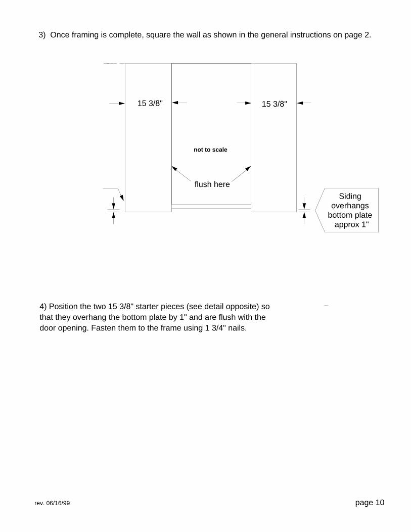
4) Position the two 15 3/8" starter pieces (see detail opposite) sothat they overhang the bottom plate by 1" and are flush with thedoor opening. Fasten them to the frame using 1 3/4" nails.
page 10rev. 06/16/99
3) Once framing is complete, square the wall as shown in the general instructions on page 2.
Sidingoverhangs
bottom plateapprox 1"
15 3/8" 15 3/8"
flush here
not to scale

3) Left Back Wall Assembly1) Lay out the two 72” and 19” left back wall plates and 6 studs on 24” centres as shown below, with theoutside section @ 19” spacing. You will have 2 wall sections (one 72”, the other 19”).2) Attach each stud to the plates using two 3” nails for each end of the stud. Ensure that the top of thestud stays flush with the plate. Fasten the two sections together using 3” nails @ 8” intervals.
���
���
���
���
��� ���

3) Once framing is complete, square the wall as shown in the general instructions on page 2.
4) LLay the two 48" panels as shown. The panels must be flush with the top plate, and overhangof tthe end stud on both sides by 2 1/2". Ensure that the bottom of the panels also overhangfrthe bottom plate by approx. 1". Fasten as before.
Siding overhangs end stud by approximately 2 1/2"
page 12rev. 06/16/99
Sidingoverhangs
bottom plateapprox.1"
96"

4) Right Back Wall Assembly1) Lay out the two 72” and 24” right back wall plates and 6 studs on 24” centres as shown below. You willhave 2 wall sections (a 72” section and a 24” section).2) Attach each stud to the plates using two 3” nails for each end of the stud. Ensure that the top of thestud stays flush with the plate. Fasten the two sections together using 3” nails @ 8” intervals.
���
���
���
���
��� ���

3) Once framing is complete, square the wall as shown in the general instructions on page 2.
4) Lay the two 48" panels as shown. The panels will be flush with the top and the sides of theframe. Make sure that the siding overhangs the bottom plate by approx. 1". Fasten as before.
page 14rev. 06/16/99
Sidingoverhangs
bottom plateapprox 1"
96"

5) Side Wall Assembly (please refer to appendix)
1) Lay the two - 48" left side wall plates (cut 22 1/2° on one end), three studs and one bevel stud as shown below.
2) Attach each stud to the plates using two - 3" nails for each end of the stud. Ensure that the topof the stud stays flush with the plate.
page 15
flush here
flush here
2 - 3" nails
rev. 06/16/99
bevel stud

3) Once framing is complete, square the wall as shown in the general instructions on page 2.
4) Position the 48" window panel as shown. The panels will be flush with the top and sides ofthe frame. Fasten as before.
page 16rev. 06/16/99
Sidingoverhangs
bottom plate1"

APPENDIX W9-5
SIDELITE WINDOW IN LEFT AND RIGHT 5-SIDED WALLS
PARTS CHECKLIST - Please compare with the parts included in your shed kit. Note that thesiding pieces are for the Cedar and Canexel Models only - Fir Panels have window openings.All Sizes:
2- Window Spacers (17 ½")
2- Sidelite Windows
Side wall for 8' 5-Sided Shed Side wall for 11' 5-Sided Shed
1- Siding - 1x8x48"(tongue cut) 1- Siding - 1x8x66"(tongue cut)
3- Siding - 1x8x48" 3- Siding - 1x8x66"
16- Siding - 1x8x15" 16- Siding - 1x8x24"
Side wall for 9' 5-Sided Shed Side wall for 12' 5-Sided Shed
1- Siding - 1x8x54"(tongue cut) 1- Siding - 1x8x72"(tongue cut)
3- Siding - 1x8x54" 3- Siding - 1x8x72"
16- Siding - 1x8x18" 16- Siding - 1x8x27"
Side wall for 10' 5-Sided Shed
1- Siding - 1x8x60"(tongue cut)
3- Siding - 1x8x60"
16- Siding - 1x8x21"
Should you have any questions or concerns, please don't hesitate to call us directly @
1-800-606-8911
or check our website@
www.gardendec.com
Made by Kenex Manufacturing Ltd.

Right Side Wall Assembly with W9 Sidelite Window
1) Lay the two right side wall plates (cut 22 1/2° on one end) with the number of studs indicated by the tablebelow . Place one bevel stud at the end as shown.2) Attach each stud to the plates using two-3" nails for each end of the stud. Ensure that the top of the studstays flush with the plate. Align the bevel stud with the end of the plates as shown in the Framing PerspectiveDrawing below.3) Position the windows spacers (2x3x17 ½") as shown in the drawing below. Using 3" nails, nail each spacertwice through each stud, ensuring that the spacer stays flush. Square the wall in the general instructions on page 2.
57 1/2"
6 1/2"
5 "
A
B
C
D
E
17 1/4"
Window Opening
Bevel Stud
Bevel Stud
5-SIDED WINDOW WALL POSITIONING
SIZE 8' 9' 10' 11' 12'A N/A N/A N/A 10 " 11 1/2"B 12" 15" 18" 20" 23"C 31" 34" 37" 39" 42"D N/A N/A N/A 51" 55"E 45 1/2" 51 1/2" 57 1/2" 62 1/2" 68 1/2"
Top Plate

Left Side Wall Assembly with W9 Sidelite Window
1) Lay the two left side wall plates (cut 22 1/2° on one end) with the number of studs indicated by the tablebelow . Place one bevel stud at the end as shown.2) Attach each stud to the plates using two-3" nails for each end of the stud. Ensure that the top of the studstays flush with the plate. Align the bevel stud with the end of the plates as shown in the Framing PerspectiveDrawing below.3) Position the windows spacers (2x3x17 ½") as shown in the drawing below. Using 3" nails, nail each spacertwice through each stud, ensuring that the spacer stays flush. Square the wall as in the general instructions on page 2.
57 1/2"
6 1/2"
5 "
17 1/4"
Window Opening
Bevel Stud
A
B
C
D
E
Bevel Stud
Top Plate
SIZE 8’ 9’ 10’ 11’ 12’
A N/A N/A 10” 12” 13”
B 14 1/2” 17 1/2” 20 1/2” 23 1/2” 26 1/2””
C 33 1/2” 36 1/2” 39 1/2” 42 1/2” 45 1/2”
D N/A N/A 50” 54” 59”
E 48” 54” 60” 66” 72”

4) Once framing is complete, square the wall as shown in the general instructions on page 2.
5) Position the 48" window panel on the frame as shown. The panel will overhang both sidesof the frame by 2 1/2" on either side. The panel will be flush with the top of the frame.Fasten as before.
rev. 06/17/99
Sidingoverhangs
bottom plateapprox 1"
Siding overhangs end stud by approximately 2 1/2"
48"

Re-check the floor before erecting the walls. It is very important thatthe floor is flat and level to insure proper installation of the roof.
1) Starting with the right back wall, lift the wall into position as shown below. Center the wall onthe floor so that the overhang, if any, is equal on both sides of the floor. Nail scrap packagingmaterial diagonally across gable wall and floor to help support the wall.
7) Erecting the Walls
Be sure to adequately support thegable wall before proceeding
2) With one person outside pushing the bottom of the wall tight against the edge of the floor, fasten wall by nailing the bottom plate to the floor at 16" intervals.
floor
nail through bottomplate every 16" with
3" nails
overhang, if anyshould be equalon both sides ofthe floor
scrappackagingmaterial
rev. 06/03/99
Erection Plan - Top View
right back wall
left back wall
left side wall
front wall
right side wall

walltop plate
wall top plate
flush here
5) With one person outside pushing the bottom of the wall tight against the edge of the floor, nailthe bottom plate to the floor at 16" intervals.
6) Next, position each of the two side walls as shown below. Ensure that the inside corners aretight with the back walls.
7) Fasten the corners together as detailed in step 4. Do not nail the side wall plates to the flooryet.
8) Slide the front wall into place between the two side walls.
9) Fasten both front wall corners Adjust the wall sections so that the top plates are flush with eachother. (this may require you to temporarily shim one of the walls. With one person pushing thecorner tight, fasten the corner together by using 3" nails to fasten the inside corner in three places,top, middle and bottom. Leave the front wall plate loose for now.
10) For each of the side walls, with one person outside pushing the bottom of the wall tight againstthe edge of the floor, nail the bottom plate to the floor at 16" intervals. Leave the front wall plateloose for now.
rev. 05/06/99
3) Slide the left back wall into place ensuring that the corner is tight with the other wall.
4) Adjust the walls so that the top plates are flush with each other (this may require you totemporarily shim one of the walls). With one person pushing the corner tight, fasten the cornertogether from the outside by nailing seven - 1 3/4" nails through the panel overhang into the gablecorner stud. Reinforce the corner by using three - 3" nails to nail the corner studs together from theinside.

8) 5-Sided Roof
Kenex Manufacturing Ltd
The following instructions provide methods to install all of our Cabana 5 sided Roofs. Roofs may vary in sizes and material, but the construction procedure remains the same.
The following pages contain explicit instructions on how to assemble your 5-Sided Cabana. Extensive diagrams and complete explanations are offered to make it simple for those who have little or no experience with a project of this nature.

Assembly Instructions
Begin by organizing your roof parts in to categories, separate hip (there will always be 3), common and jack rafters in to separate piles. You’ll also have one 8 sided hub, and your top plates. A helpful hint when building smaller 5 sided roofs, is to start assembly of your roof on the floor, then set it aside when your walls are erected and your roof can be placed on top. Doing it this way can make for a heavy lift, but if you manage to bribe the neighbours into helping, its an easier way to assemble it. *Note* These instructions can be used for any sized unit, although the material and rafter count may differ. E.g.: Larger units consist of more jack rafters. Note the back wall plates are in 2 pieces each.
1.Lay your double top plates out using this diagram. Pay special attention to the order of the double top plates. Its easy to mix them up, so take your time and lay them out properly. The double plates plates will sit on top of your walls, they can be secured to your walls using 3” screws or nails approx. every 10”-12”
LEFT
S IDE
FRONT WALL
RIGHT SIDE
Longest Plate
7" Shorter Than Longest Plate
Left Side Plate Is Always Shorter Than Right Side
The next step will show you how to mark the locations of your common and hip rafters. It may be easier to mark your double top plates on the ground.It should be noted before assembling your roof, that rafters may not seem to fit properly, it will take some adjusting and maneuvering of walls, rafters etc. for the roof to achieve an accurate fit. Be aware there will be slight variances when assembling the structure.

Assembly Instructions
2.Clearly mark your plates andrememberthat there will be 3/4” on either side of the center mark. An1 ½” total, to accommodateyour rafters.
Center CommonRafter On This Point,
Center CommoRafter On 1/2Way Mark.
Center Common On 1/2 Way Mark
Center Common Rafter On ThisPoint.
Center Front RafterOn 1/2 Way Mark
Center Hip RaftersOn Outside Corner
3.Begin by assembling your 3 hip rafters first.Use 3-4 3” screws to secure them to the 3 corners, and another 3-4 screws to secure into your hub. It may be easier to assemble left & right hips to hub 1st, then lift into place and secure back hip rafter to form a tripod.
Hip Rafters (3)
8 Sided Hub

Assembly Instructions
4.The cuts at the end of your rafters are referred to as the “birds mouth” When placing all your rafters be sure that the birds mouth is snug with your top plates. And use three 3” screws to secure your rafters into the plates. It will take some muscle to hold and screw them tight into place.
Ensure the"birds mouth"is snug with the top plate Secure to top
plate using 3"screws
5.Install your 4th
rafter, the front rafter the same way as your hips. Your ready to install your common rafters. If they don’t seem to fit properly, you may have to push or pull down on the hub (peak) or may even have to push or pull the walls, these roofs can be tricky and it will take some patience to achieve a good fit.
CommonRafters (4)
(1)Front Rafter

Assembly Instructions
6.Depending on the size of your roof, between 6-18 (1-3 sets) jacks are required. Jack rafters are secured into hip rafters, there will be1-left & 1-right. Jack rafters can be maneuveredslightly, their position can be altered to accommodateroof boards. Use 3” screws to secure.
Jack Rafters(6) Per SetLeft & Right
Note.When you receive your plans, you will notice that the Osb roofing boards we show come in full 4’ x 8’ sheets. The reason for this is because when roofs are assembled there is always a slight variance. Each roof has to be custom fitted with the Osb board we have given you. We apologize for the inconvenience, but we must do it this way to assure a proper fitting and supporting roof structure. Ideally you want the rough side of the Osb facing up, this will supply grip for applying the shingles. There are 2 ways to go about this. (see next page for details, diagram 8 and 9)

Assembly Instructions
7.Set back ½” or approx. a “finger width”. This will eventually be cover with your shingles, so the distance is flexible, but that gap should not be too large. Rafter
Top Plate
Osb Roof Board
Approx. 1/2 "
8.1. Take a full sheet, and tack it into place using 2” nails. Typically you want all vertical seams to center on your rafters. Cover as much roof as possible with one piece, the less cuts to make the better. Remember that Osb roof boards should not come down flush with the rafters ends, they should sit back appox. a “finger width” from the end. Figure 7 on previous page. Once your board is in place and you feel confident to use a saw on the roof, use a chalk line to mark the Osb up the hip rafter.Using a circular saw. Cut along the chalk line. Don’t throw away your cut off, it can be used somewhere else. See figure 8a.
2. The alternative is to use your tape measure to obtain the measurements to mark and cut. Measure A, remember your measurements are always to the middle of the rafter. Make a mark on your roof board for A. Now measure B, mark your roof board where B is. Use a straight edge or a chalk line to mark a cutting line between A & B. The result will be C, this is the line to run your saw along. The piece can now be lifted into place and tacked into place using 2” nails. See figure 8b.

Assembly Instructions - start with the small panels at the bottom.
8a. 8b.
A
B
C
9.Rememberthat off cuts can be used elsewhere on the roof, usually on the opposite side from where the off cut came. Its also a good idea to stagger your seams as much as possible, the diagram gives a general idea of staggeringseams. This strengthensthe overall integrity of the roof.

Assembly Instructions
The roof will be tricky, but doing like this will achieve the best fit possible. Secure your roof boards into place using 1 1/2” nails approx. every 8”. That’s it, your roof is framed and sheeted, now it’s time to move onto your trim!

Assembly Instructions
9. 5 Sided Roof Trim Assembly
The following instructions provide methods to install all of our Cabana Hip Roof trim. Trim may vary in sizes and material, but the construction procedure remains the same.
The following pages contain explicit instructions on how to assemble your 5-Sided Cabana. Extensive diagrams and complete explanations are offered to make it simple for those who have little or no experience with a project of this nature.

Assembly Instructions
Trim Assembly
Begin by organizing all your trim parts. Separate them by their length and width. It should be noted that most of the trim should be cut long, you will need to make some cuts yourself, using a handsaw and/or a circular saw. These measures are taken to ensure the cedar is top quality, and if any minimal cracking that has occurred it can be cut off.
1.Typically we start with the soffits. Soffits are the cedar trim that are attached to the underside of the rafter ends. On smaller units, the soffits will all be the length of the building. However, on our larger units the soffits will be cut into two or more pieces. They should always meet centered on a rafter. Standard overhang roof’s will consist of one course, and extra overhang roof’s will have two courses. Take a piece of trim that has a 45 degree angle on one end, center the cut on the hip rafter (corner) while the piece is held in position, mark the opposite end to the center of the closest rafter. Make a straight cut across, use two 2” nails to fasten into position.
1st Course(standardoverhang)
Staggered Joints(extra overhang)
2nd Course(extra overhang)
1st CutStnd/extra

Assembly Instructions
2.The short side walls trim is cutstraight.The front wall trim is cut at 22.5*A small corner will have to be cut off. Nail it into place and hand saw it following the side wall soffitsstraightacross.
These corners can be tricky, you will have to cut off a small corner to accomodate joiningtrim.
3.It should be noted that when your soffits are complete, they should comepast the end of your rafters.
Rafter
Wall 2nd Course ExtraOverhang
1st CourseStandardOverhang
Fascia
Fascia is not flushwith rafter

Assembly Instructions
4a.Fascia is the cedar trim that runs vertically around the structure. It is used to cover your rafter ends. The top of the fascia should come up level where the angle on the rafter ends.Use arrow as a gauge.
Rafter
Wall
FasciaSoffits
4b.All the trim is secured using 1 1/2” nails. Take your time when nailing your fascia into the soffits, be careful your nails are directly into the soffits.Fascia will also be cut long to avoid cracked ends. Fascia on the front and the back of your structure will come past your side fascia. On larger units your fascia will also come in more than one piece. Just be sure to push joints tight to one another. To cut your fascia to the right size, either hold it up to its position, mark, and the cut it on the ground.Another possibility is to nail your fascia into the soffits and then cut while its in place.
Its not until you have assembled your soffits and fascia that you can begin shingling. Window trim is already assembled with your windows, certain windows may require additional trimming, but generally is limited to one piece and is self explanatory. See the included documents on how to install the door you have purchased.

Assembly Instructions
4c.
RafterFascia
5.Identify your skirts, will be full width pieces of trim. It will take some cutting and or digging grooves to custom fit the pieces to the grade of the ground.Try to minimize space between the ground and your skirts.

Assembly Instructions
6.Nail side cornersflush with front walls.The front cornershouldcover the edge of side corner.Cornersshould be pushedright up to soffits and shouldcome down to bottom of skirts.
Flush WithSoffits
Flush with BottomOf Skirts
Corner Trim (2)
Side Corner
Front Corner
7.The front wall to side wall corner trim is a little bit different. You will notice that these trim pieces are ripped on an angle up the
side. The are joined together like the opposite
drawing.SideWall
FrontWall
Your trim is complete, your nearing completion!

Assembly Instructions
Notes:
- Door and window trim separate.
- Shingles are now ready forinstallation, we recommend following the manufacturer’s instructions because installation procedures may vary.
Notes:

Deluxe and French Door Appendix1) Cut out the bottom plate where it crosses the door opening. Use a handsaw and cut the plateflush with the door studs. The rough opening should now be 36 1/2" x 73 1/2".
2) Decide which way you want your door to operate. It may be hinged on either side and mayswing in or out (consider the intended use of your shed and possible space constraints). Laythe door on the floor of the shed and arrange the horizontal door jamb, the vertical door jambsand the threshold around it. See Door Layout Detail.
41"
36"
34"
1/4" 1/4"
71 7
/8"
71 1
/2"
3/16
"3/
16"
8"
8"
horizontaldoor jamb
threshold
verticaldoor jamb
Door Layout Detail
thresholdsupport
rev. 02/03/00 page 24

3/16"approx.
3 1/2"
8"
leave this hole empty
8"
leave this hole empty
flushhere
flushhere
3/16"approx.
3/16"
(app
rox)
8"
vertic
al
door
jamb
flushhere
flushhere
Hinge Detail 2
door
3) Place one hinge 8" from the bottom of the door, and the other hinge 8" from the top of thedoor. Ensure that the top of the hinge-pins point to the top of the door and that the front edgesof the hinge plates are flush with the face of the door. See Hinge Detail 1 and 2. Attach thehinges to the door using the 1 1/4" screws provided.
4) Place on of the vertical door jambs on edge on the door face next to the hinges. Position thejamb so that the overhang is the same at the top and bottom of the door. Flip the hinges openso they lay flat against the 3 1/2" face of the jamb. Lift the jamb up until the back edge of thehinge plate is flush with the edge of the jamb. Attach the hinge to the jamb using only twoscrews, leave the middle hole empty (this is where the jamb will be attached to the door stud).These screws will protrude through the back of the jamb, but should not interfere with theinstallation of the door. See Hinge Detail 1 and 2.
5) Now flip the hinged jamb to the closed position. Attach the horizontal door jamb to thevertical jamb using either three - 1 3/4" nails or two - 2 1/2" screws provided (pre-drill holes if youuse the screws). Make sure that the horizontal jamb is flush with the end and edge of thevertical jamb.
rev. 02/03/00 page 25
Hinge Detail 1

6) Now attach the threshold to the bottom of the vertical jamb. The front of the threshold is theedge that has the 2 1/2" tabs ( these tabs go flush to the outside of the front wall panels). Keepthis edge facing the right way (this depends if your door swings in or out). Keep the inside edge ofthe threshold flush to the inside edge of the vertical jamb and the outside edge of the thresholdflush to the outside face of the vertical jamb. Nail or screw as in step 5. See Threshold Detail.
7) Attach the other vertical jamb in the same manner as the first.
8) Stand the door into the opening and make sure that the jambs are flush to the outside of thewall panels. Check the gap between the door and the jambs - it should be even around all sides. Ifnecessary, use the shims provided to shim the door behind each hinge in order to even out the gap(split the shims as required so that you will have enough). If the hinged jamb is tight to the doorstud and the gap around the door is even, the shims are not necessary. Open the door and attachthe jamb through the third hole in each hinge using the 2 1/2" screws provided.
9) Shim the other vertical jamb and door stud at the top, middle, and bottom. Make sure that thegap between the door and the jamb is even. Using 2 1/2" screws, attach the jamb to the shims anddoor stud. Center the screws in the middle of the jamb so that when the door stop is attached, itwill hide the screws.
10) Mount the lock set according to the manufacturer's instructions.
11) Close the door and place the vertical door stop on the left and right side of the door. Positionthe stop so that it is flush to the door face. Do not push the stop too tight to the door, as this willimpede the performance of the door and lock set. Nail the door stop to the jambs using five - 1 3/4"nails per stop. Nail the horizontal door stop between the tops of the vertical door stops (you maywish to temporarily shim the horizontal door jamb with scrap material to avoid forcing the jambsapart at the top).
12) Using four - 1 3/4" nails, attach the threshold support to the wall under the lip of the threshold.The ends should be flush with the ends of the threshold. See Door Layout Detail.
13) Place the vertical door casing on the threshold lip. Position the casing approximately 1/8" to1/4" from the inside edge of the jamb. Attach using five - 1 3/4" nails. Repeat for the other side ofthe door. See Door Casing Detail.
14) Center the horizontal door casing on top of the vertical casing and attach with three nails.
Threshold Detail
rev. 02/03/00 page 26
flushhere
flushhere
outside edge
inside edge
threshold
vert
ical
jam
b
verticaldoor
casing
verticaldoorjamb
threshold
approx. 1/8" - 1/4"
of jamb left
exposedDoor Casing Detail
thresholdsupport

Using four nails per shingle, nail as shown in drawing. Drive nails straight so that the nail head is flush with,but not cutting intoshingle surface.
Follow illustrations to apply Shingles to your Building.
After completing shingling your building, remove any overhanging, excess shingles by cutting them off with a utility knife.
INSTALLING ASPHALT SHINGLES (REQUIRED)
1"(2.5 cm)
NAILS
Sealing Strip1"
(2.5 cm)1/2"
(1.3 cm)
First row of Shingles are installed backwardsto make a seal barrier-flush to bottom of Drip Edge
It is okay if last Shingle overlaps it will be cut
off later
Line up notch ontop of Shingle with
edge of Roof to staggerthe Shingles
Line up notch onside of Shingle with
edge of Roof to staggerthe Shingles
Roof
Shingle

Roof Panel
Nail That Missed Stud
Trim NailsNot in Studs
See requirements in the limited conditional warranty on the last page of this manual.
After assembly is finished, check the entire building inside andout for any protruding nails. Pound any protruding nails intothe wood or cut them off flush.
Keep GrassTrimmed
See Warranty Requirements
Keep SprinklersAway From Building
To cover the Peak of your building, cut stripShingles into individual pieces by dividingat cutout as shown. Bend each piece overthe Peak and nail 5-7/8” (14.9cm) abovethe butt edge and 1”(2.5cm) in from eachside, exposing each piece 5-1/8” (13cm) tothe weather.
REQUIRED MAINTENANCE
NAIL INSPECTION
Cut any ShinglesOverhanging Sides
Cut single Shingleinto three pieces
5-1/8"(13cm)
5-7/8"(14.9cm)
INSTALLING SHINGLES (CONTINUED)

Limited ConditionalWarranty
WARRANTYWe warrant the following:
1. Every product is warranted from defects in workmanship and manufacturing for two years.2. All hardware and metal components are warranted for two years.3. Trim is warranted for 3 years.4. Waferboard siding and sheathing is warranted for two years.5. T 1-11, Cedar and Canexel siding are warranted for 15 years.
We will repair, replace or pay for the affected part. In no event shall we pay the cost of labor or installation or any other costs relatedthereto. All warranties are from date of purchase. If a cash refund is paid on an affected part, it will be prorated from the date ofpurchase. Note that due to the organic nature of wood, knots, small cracks and minor movement are not considered defects.
CONDITIONSThe warranty is effective only when:
1. The unit has been erected in accordance with the assembly instructions.2. The unit has been properly shingled and painted or stained and reasonably and regularly maintained thereafter.3. The failure occurs when the unit is owned by the original purchaser.4. We have received the warranty registration card within thirty (30) days of purchase and notification of the failure in writing
within the warranty period specified above.5. We have had reasonable opportunity during the sixty (60) days following receipt of notification to inspect and verify the
failure prior to commencement of any repair work.
REQUIREMENTSTo validate your warranty, it is necessary to properly maintain your building; shingle the roof and paint or solid-colored stain the sidingusing 100% acrylic latex exterior product with a minimum of two (2) coats within thirty (30) days of assembly; caulk above all doors andall horizontal and vertical trim boards; paint and seal all exposed edges, sides and faces of siding to include all exterior walls andall sides and all edges of doors.
Other RequirementsKeep vegetation trimmed away from building. Water from sprinklers must be kept off unit. In no event will we be responsible for anyindirect, incidental, consequential or special damages nor for failure(s) that are caused by events, acts or omissions beyond our controlincluding, but not limited to, misuse or improper assembly, improper maintenance (which eventually leads to rot or decay) and acts ofGod. We will not be held responsible for any labor costs incurred to construct your unit.
CLAIM PROCEDURETo make a claim under this warranty, call (800) 606-8911. Please have ready the information below when you call or include theinformation when writing:
1. The model and size of the product.2. A list of the part(s) for which the claim is made.3. Proof of purchase of the item, as shown on the original invoice.
IMPORTANT: This is your warranty certificate.Please complete and mail your warranty card to properly validate your warranty.

Simply send us a photo of your completed structure and be eligible to win $250.00.
On December 30th we'll choose what we consider to bethe nicest shot, and mail the winner a cheque.
Elements such as lighting, location, landscaping andstain or paint application will be taken into considera-tion as well as the overall appeal of the photograph.
GOOD LUCK!
It’s Done!
The location is grand, the
landscaping is divine, the colour
scheme matches the surroundings
perfectly. What’s left to
do?
Win $250.00
Cash!
rev. 02/02/00 ver. 2.00

Please detach and return the card (or fax) to the address below (with copy of dated retail receipt) to validate your warranty.
Warranty Registration Card
Name: Model:Address: Date Purchased:City: Retail Outlet:Province/State: Store Location:
We would appreciate a moment of your time to answer the following questions:
Did you find the instructions clear? Yes NoIf not please explain
Did you encounter any difficulties with assembly? Yes NoIf so please explain
Kenex Manufacturing Ltd27 Regan Rd, Brampton, ON
L7A 1B2Tel. 1-800-606-8911 (Locally 905-840-9469)
Fax 905-840-6904email: [email protected]