Embed Size (px)
Citation preview
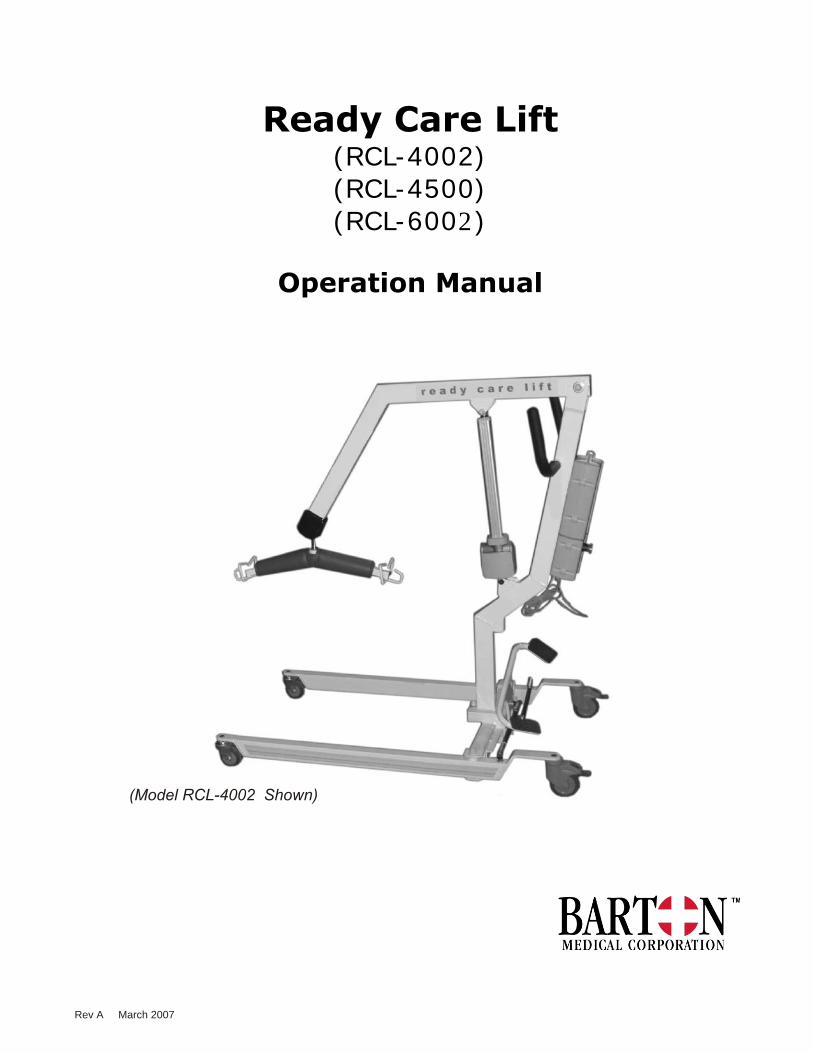
Ready Care Lift(RCL-4002)(RCL-4500)(RCL-6002)
Operation Manual
(Model RCL-4002 Shown)
Rev A March 2007

Page #Warnings 1
Warranty 2
Ready Care Lift (Model 4002) Specifications 3
Ready Car Lift (Model 4500) Specifications 4
Bariatric Ready Care Lift (Model 6002) Specifications 5
Ready Care Lift Overview 6
Assembly 7
Operation 8
Operation (special instructions for lifting from a vehicle 10
Slings
- Loading in a Seated Position 11
- Loading in a Recumbent Position 12
- Positioning the Legs 13
- Sling Care 14
Transfers 15
Interchangeable Battery System Overview 17
IBS Technical Data 18
Placing and Removing the Battery Pack 19
Installing the Charging Station 20
Ready Care Lift Scale (optional) 22
Scale Attachment (optional) 23
Scale Operation (optional) 24
Ready Care Lift - Major Components 25
Hanger Assmebly - Detail View 26
Interchangeable Battery System - Bariatric 27
Placing and Removing the Battery - Bariatric 28
Maintenance 29
Troubleshooting 30
Note: The maintenance checklist located in the back of the manual should be
photocopied and used to record your Ready Care Lift inspections.
Reminder:Do not forget to complete and return the warranty card located in the back of the
Ready Care Lift manual.
Ready Car Lift Overview 9
TABLE OF CONTENTS
DO NOT ATTEMPT TO SETUP OR OPERATE THE READY CARE LIFT WITHOUT THOROUGHLY REVIEWING THE CONTENTS OF THIS MANUAL! FAILURE TO DO SO MAY RESULT IN SERIOUS INJURY,
EQUIPMENT FAILURE, AND/OR VOID WARRANTY.
If you have any questions regarding the setup or operation of the Ready Care Lift, please contact:
AFFIX DEALER CONTACTINFORMATION HERE
Or contact Barton Medical:1-800-387-7103
THE READY CARE LIFT FROM BARTON MEDICAL HAS BEEN INSPECTED TO C.S.A. (CANADIAN STANDARDS ASSOCIATION) GUIDELINES.
WARNINGS
1
WARRANTY
Warranties are limited to manufacturer’s defects and exclude the effects of normal wear and tear, unintended use, operator abuse, concussive impacts and external factors including exposure to heat lamps, vapours, chlorine and other corrosive substances. Barton Medicals’ liability under warranties is limited to replacing defective parts and does not extend to consequential damages. Warranties are voided by unauthorized repairs or modifications to the equipment.
Structure(includes structural frame)Lifetime warranty. Does not include damage to enamel caused from wear and/or operator abuse.
Arm Grips, Safety StrapsNinety day warranty against manufacturers defects.
All Other ComponentsAll other components of the Ready Care Lift, including castors and Interchangeable Battery System have a one year warranty.
Please complete the warranty card and return it immediately to:
Canada/International:Barton Medical Canada
5510 Mainway Burlington, Ontario
L7L 6C4
United States:Barton Medical Corporation
5725 Hwy 290 West, Suite 103Austin TX 78735
Or Fax it to: 905-336-1708
This manual contains operating, maintenance and service instructions for the Ready Care Lift.
It is the user's responsibility to ensure the correct use of Ready Care Lift and coordinate the maintenance schedule to maintain good operating condition.
Specifications remain subject to change to allow the introduction of design improvements and will be done without notice.
2

PRODUCT NUMBER: RCL-4002
OPERATION: Electric Actuator
POWER SOURCE: 24 V (4.5 Amp)
BOOM, Highest Position: 70” (178 cm)
BOOM, Lowest Position: 23” (58 cm)
MAXIMUM CAPACITY: 500 lbs (182 kg)
OVERALL LENGTH: 45½” (116 cm)
BASE/LEG WIDTH, Closed: Inside - 21¼” (54 cm)
Outside 25¾” (65 cm)
BASE/LEG WIDTH, Open: Inside - 44” (112 cm)
Outside 49” (125 cm)
FRONT CASTERS, Dual wheel: 3” (8 cm)
REAR CASTERS, Single w/brake: 4” (10 cm)
OVERALL WEIGHT: 120 lbs (54.4 kg)
CONSTRUCTION: Rectangular steel tubing
FINISH: Polyester powder coat, baked
EMERGENCY STOP SWITCH: Standard
EMERGENCY LOWERING SWITCH: Standard
LOW BATTERY LEVEL LIGHT: Standard
LOW BATTERY AUDIBLE INDICATOR: Standard
ELECTRIC HAND CONTROL: StandardBATTERY CHARGING
(on unit or at remote location): Standard
CHARGING TIME (FROM EMPTY): 9 hours (4.5 Amp battery with
500mA charging)
LIFTS PER CHARGE (under maximum load): 36 Cycles
READY CARE LIFT SPECIFICATIONS
3
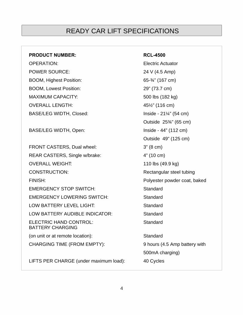
PRODUCT NUMBER: RCL-4500
OPERATION: Electric Actuator
POWER SOURCE: 24 V (4.5 Amp)
BOOM, Highest Position: 65-¾” (167 cm)
BOOM, Lowest Position: 29” (73.7 cm)
MAXIMUM CAPACITY: 500 lbs (182 kg)
OVERALL LENGTH: 45½” (116 cm)
BASE/LEG WIDTH, Closed: Inside - 21¼” (54 cm)
Outside 25¾” (65 cm)
BASE/LEG WIDTH, Open: Inside - 44” (112 cm)
Outside 49” (125 cm)
FRONT CASTERS, Dual wheel: 3” (8 cm)
REAR CASTERS, Single w/brake: 4” (10 cm)
OVERALL WEIGHT: 110 lbs (49.9 kg)
CONSTRUCTION: Rectangular steel tubing
FINISH: Polyester powder coat, baked
EMERGENCY STOP SWITCH: Standard
EMERGENCY LOWERING SWITCH: Standard
LOW BATTERY LEVEL LIGHT: Standard
LOW BATTERY AUDIBLE INDICATOR: Standard
ELECTRIC HAND CONTROL: StandardBATTERY CHARGING
(on unit or at remote location): Standard
CHARGING TIME (FROM EMPTY): 9 hours (4.5 Amp battery with
500mA charging)
LIFTS PER CHARGE (under maximum load): 40 Cycles
READY CAR LIFT SPECIFICATIONS
4
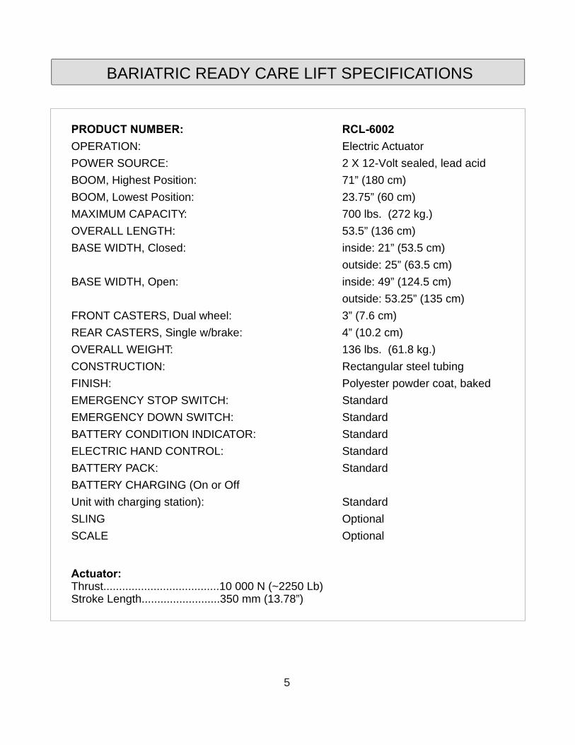
PRODUCT NUMBER: RCL-6002
OPERATION: Electric Actuator
POWER SOURCE: 2 X 12-Volt sealed, lead acid
BOOM, Highest Position: 71” (180 cm)
BOOM, Lowest Position: 23.75” (60 cm)
MAXIMUM CAPACITY: 700 lbs. (272 kg.)
OVERALL LENGTH: 53.5” (136 cm)
BASE WIDTH, Closed: inside: 21” (53.5 cm)
outside: 25” (63.5 cm)
BASE WIDTH, Open: inside: 49” (124.5 cm)
outside: 53.25” (135 cm)
FRONT CASTERS, Dual wheel: 3” (7.6 cm)
REAR CASTERS, Single w/brake: 4” (10.2 cm)
OVERALL WEIGHT: 136 lbs. (61.8 kg.)
CONSTRUCTION: Rectangular steel tubing
FINISH: Polyester powder coat, baked
EMERGENCY STOP SWITCH: Standard
EMERGENCY DOWN SWITCH: Standard
BATTERY CONDITION INDICATOR: Standard
ELECTRIC HAND CONTROL: Standard
BATTERY PACK: Standard
BATTERY CHARGING (On or Off
Unit with charging station): Standard
SLING Optional
SCALE Optional
Actuator:Thrust.....................................10 000 N (~2250 Lb)Stroke Length.........................350 mm (13.78”)
BARIATRIC READY CARE LIFT SPECIFICATIONS
5
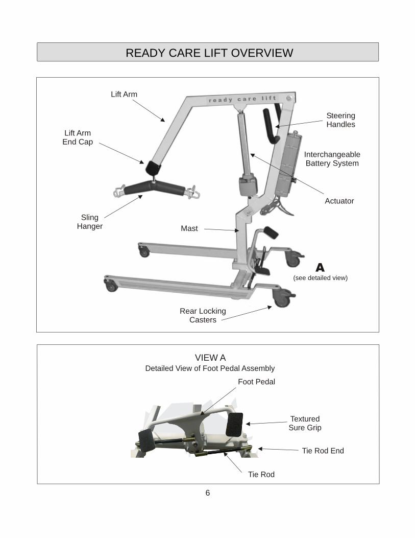
Foot Pedal
Tie Rod
Tie Rod End
VIEW ADetailed View of Foot Pedal Assembly
TexturedSure Grip
A(see detailed view)
InterchangeableBattery System
Mast
Actuator
Lift Arm
SteeringHandles
Rear LockingCasters
SlingHanger
Lift ArmEnd Cap
READY CARE LIFT OVERVIEW
6
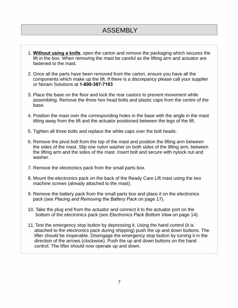
1. Without using a knife, open the carton and remove the packaging which secures the lift in the box. When removing the mast be careful as the lifting arm and actuator are fastened to the mast.
2. Once all the parts have been removed from the carton, ensure you have all the components which make up the lift. If there is a discrepancy please call your supplier or Noram Solutions at 1-800-387-7103
3. Place the base on the floor and lock the rear castors to prevent movement while assembling. Remove the three hex head bolts and plastic caps from the centre of the base.
4. Position the mast over the corresponding holes in the base with the angle in the mast tilting away from the lift and the actuator positioned between the legs of the lift.
5. Tighten all three bolts and replace the white caps over the bolt heads.
6. Remove the pivot bolt from the top of the mast and position the lifting arm between the sides of the mast. Slip one nylon washer on both sides of the lifting arm, between the lifting arm and the sides of the mast. Insert bolt and secure with nylock nut and washer.
7. Remove the electronics pack from the small parts box.
8. Mount the electronics pack on the back of the Ready Care Lift mast using the two machine screws (already attached to the mast).
9. Remove the battery pack from the small parts box and place it on the electronics pack (see Placing and Removing the Battery Pack on page 17).
10. Take the plug end from the actuator and connect it to the actuator port on the bottom of the electronics pack (see Electronics Pack Bottom View on page 14).
11. Test the emergency stop button by depressing it. Using the hand control (it is attached to the electronics pack during shipping) push the up and down buttons. The lifter should be inoperable. Disengage the emergency stop button by turning it in the direction of the arrows (clockwise). Push the up and down buttons on the hand control. The lifter should now operate up and down.
ASSEMBLY
7
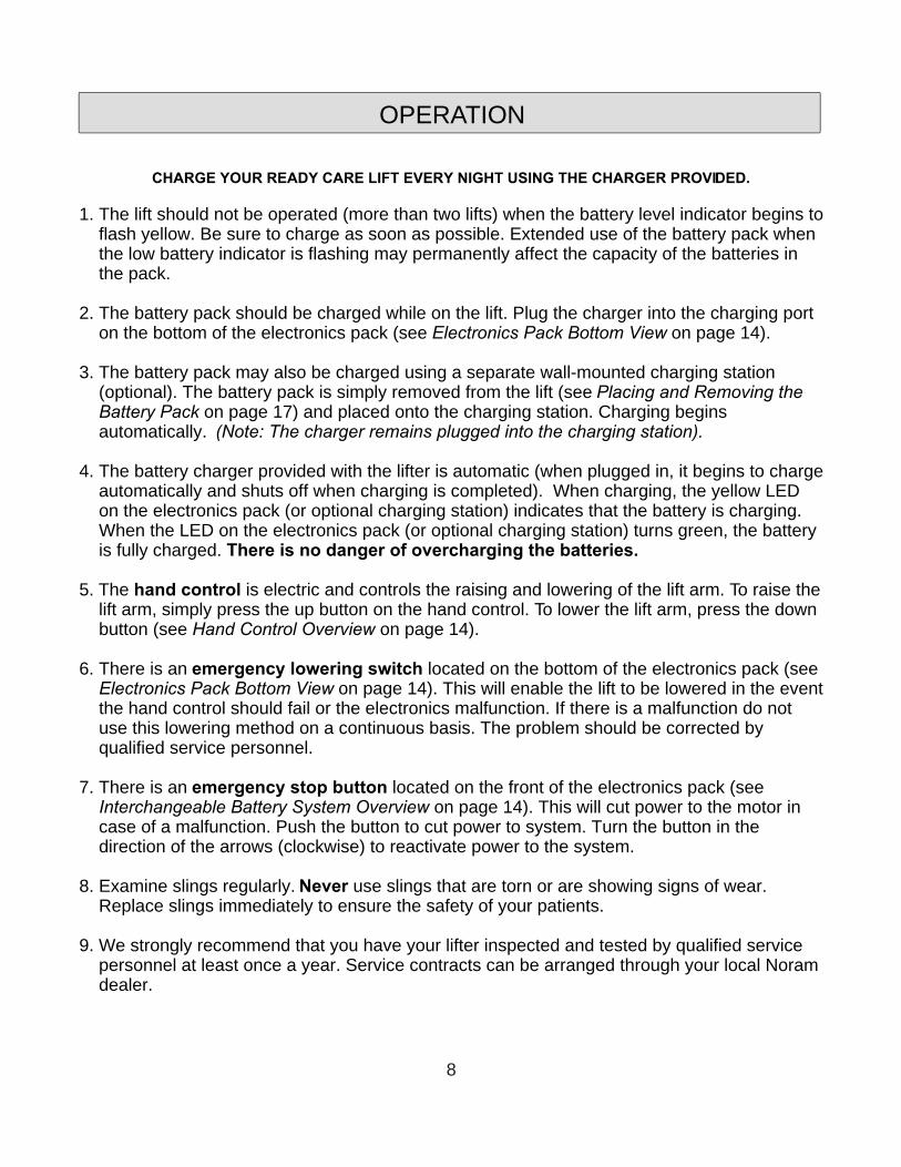
CHARGE YOUR READY CARE LIFT EVERY NIGHT USING THE CHARGER PROVIDED.
1. The lift should not be operated (more than two lifts) when the battery level indicator begins to flash yellow. Be sure to charge as soon as possible. Extended use of the battery pack when the low battery indicator is flashing may permanently affect the capacity of the batteries in the pack.
2. The battery pack should be charged while on the lift. Plug the charger into the charging port on the bottom of the electronics pack (see Electronics Pack Bottom View on page 14).
3. The battery pack may also be charged using a separate wall-mounted charging station (optional). The battery pack is simply removed from the lift (see Placing and Removing the Battery Pack on page 17) and placed onto the charging station. Charging begins automatically. (Note: The charger remains plugged into the charging station).
4. The battery charger provided with the lifter is automatic (when plugged in, it begins to charge automatically and shuts off when charging is completed). When charging, the yellow LED on the electronics pack (or optional charging station) indicates that the battery is charging. When the LED on the electronics pack (or optional charging station) turns green, the battery is fully charged. There is no danger of overcharging the batteries.
5. The hand control is electric and controls the raising and lowering of the lift arm. To raise the lift arm, simply press the up button on the hand control. To lower the lift arm, press the down button (see Hand Control Overview on page 14).
6. There is an emergency lowering switch located on the bottom of the electronics pack (see Electronics Pack Bottom View on page 14). This will enable the lift to be lowered in the event the hand control should fail or the electronics malfunction. If there is a malfunction do not use this lowering method on a continuous basis. The problem should be corrected by qualified service personnel.
7. There is an emergency stop button located on the front of the electronics pack (see Interchangeable Battery System Overview on page 14). This will cut power to the motor in case of a malfunction. Push the button to cut power to system. Turn the button in the direction of the arrows (clockwise) to reactivate power to the system.
8. Examine slings regularly. Never use slings that are torn or are showing signs of wear. Replace slings immediately to ensure the safety of your patients.
9. We strongly recommend that you have your lifter inspected and tested by qualified service personnel at least once a year. Service contracts can be arranged through your local Noram dealer.
OPERATION
8
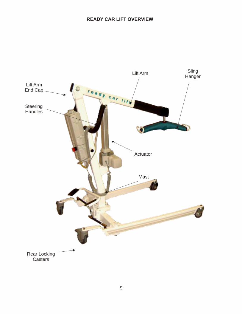
READY CAR LIFT OVERVIEW
Lift Arm
SteeringHandles
Lift ArmEnd Cap
SlingHanger
Rear LockingCasters
Mast
Actuator
9
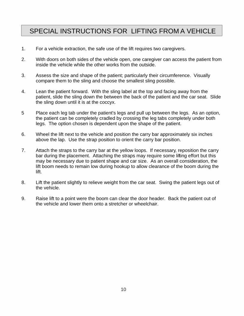
1. For a vehicle extraction, the safe use of the lift requires two caregivers.
2. With doors on both sides of the vehicle open, one caregiver can access the patient from inside the vehicle while the other works from the outside.
3. Assess the size and shape of the patient; particularly their circumference. Visually compare them to the sling and choose the smallest sling possible.
4. Lean the patient forward. With the sling label at the top and facing away from the patient, slide the sling down the between the back of the patient and the car seat. Slide the sling down until it is at the coccyx.
5 Place each leg tab under the patient's legs and pull up between the legs. As an option, the patient can be completely cradled by crossing the leg tabs completely under both legs. The option chosen is dependent upon the shape of the patient.
6. Wheel the lift next to the vehicle and position the carry bar approximately six inches above the lap. Use the strap position to orient the carry bar position.
7. Attach the straps to the carry bar at the yellow loops. If necessary, reposition the carry bar during the placement. Attaching the straps may require some lifting effort but this may be necessary due to patient shape and car size. As an overall consideration, the lift boom needs to remain low during hookup to allow clearance of the boom during the lift.
8. Lift the patient slightly to relieve weight from the car seat. Swing the patient legs out of the vehicle.
9. Raise lift to a point were the boom can clear the door header. Back the patient out of the vehicle and lower them onto a stretcher or wheelchair.
SPECIAL INSTRUCTIONS FOR LIFTING FROM A VEHICLE
10
LOADING IN A SEATED POSITION
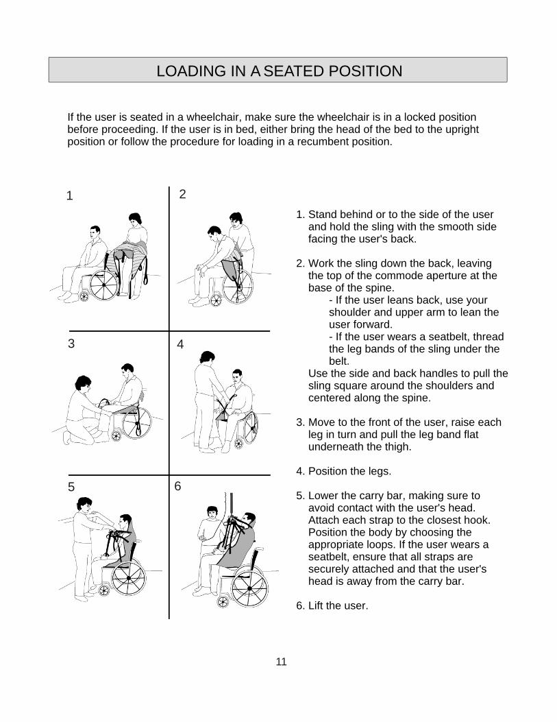
1. Stand behind or to the side of the user and hold the sling with the smooth side facing the user's back.
2. Work the sling down the back, leaving the top of the commode aperture at the base of the spine.
- If the user leans back, use your shoulder and upper arm to lean the user forward.- If the user wears a seatbelt, thread the leg bands of the sling under the belt.
Use the side and back handles to pull the sling square around the shoulders and centered along the spine.
3. Move to the front of the user, raise each leg in turn and pull the leg band flat underneath the thigh.
4. Position the legs.
5. Lower the carry bar, making sure to avoid contact with the user's head. Attach each strap to the closest hook. Position the body by choosing the appropriate loops. If the user wears a seatbelt, ensure that all straps are securely attached and that the user's head is away from the carry bar.
6. Lift the user.
If the user is seated in a wheelchair, make sure the wheelchair is in a locked position before proceeding. If the user is in bed, either bring the head of the bed to the upright position or follow the procedure for loading in a recumbent position.
1 2
3 4
5 6
11
LOADING IN A RECUMBENT POSITION
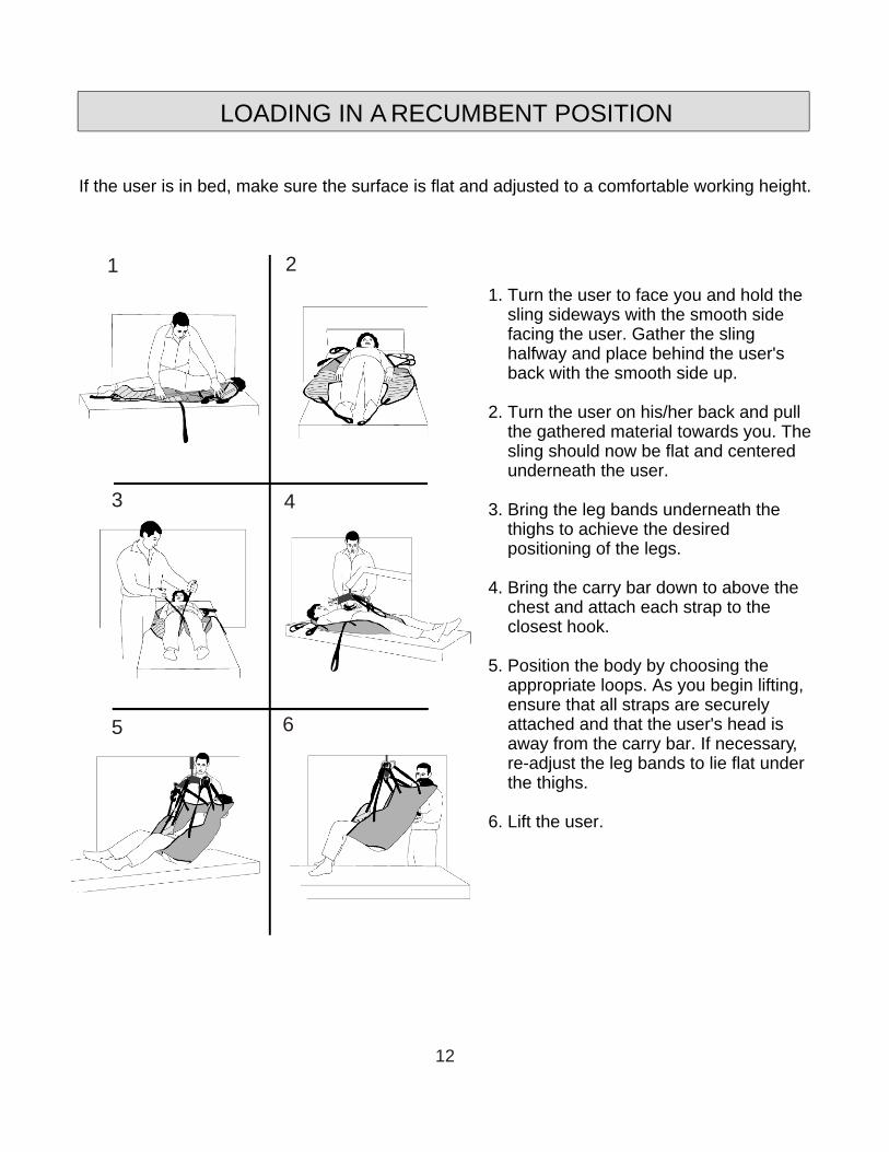
1. Turn the user to face you and hold the sling sideways with the smooth side facing the user. Gather the sling halfway and place behind the user's back with the smooth side up.
2. Turn the user on his/her back and pull the gathered material towards you. The sling should now be flat and centered underneath the user.
3. Bring the leg bands underneath the thighs to achieve the desired positioning of the legs.
4. Bring the carry bar down to above the chest and attach each strap to the closest hook.
5. Position the body by choosing the appropriate loops. As you begin lifting, ensure that all straps are securely attached and that the user's head is away from the carry bar. If necessary, re-adjust the leg bands to lie flat under the thighs.
6. Lift the user.
If the user is in bed, make sure the surface is flat and adjusted to a comfortable working height.
1 2
3 4
5 6
12
POSITIONING THE LEGS
POSITIONING THE BODY
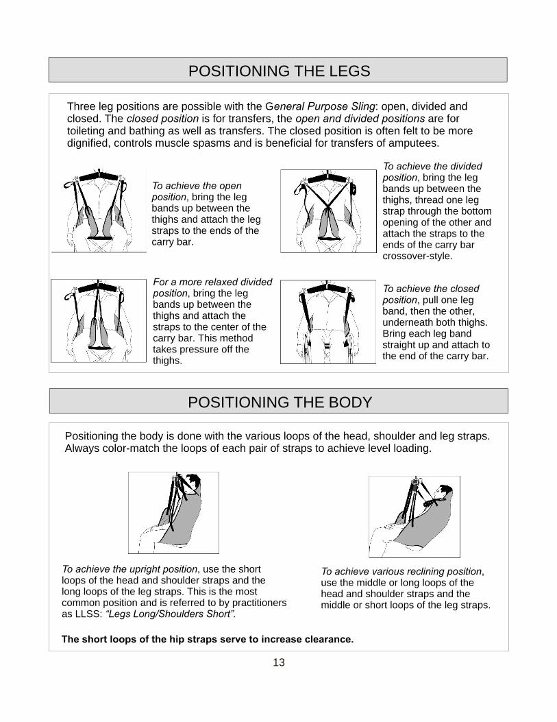
Three leg positions are possible with the General Purpose Sling: open, divided and closed. The closed position is for transfers, the open and divided positions are for toileting and bathing as well as transfers. The closed position is often felt to be more dignified, controls muscle spasms and is beneficial for transfers of amputees.
To achieve the open position, bring the leg bands up between the thighs and attach the leg straps to the ends of the carry bar.
To achieve the divided position, bring the leg bands up between the thighs, thread one leg strap through the bottom opening of the other and attach the straps to the ends of the carry bar crossover-style.
For a more relaxed divided position, bring the leg bands up between the thighs and attach the straps to the center of the carry bar. This method takes pressure off the thighs.
To achieve the closed position, pull one leg band, then the other, underneath both thighs. Bring each leg band straight up and attach to the end of the carry bar.
Positioning the body is done with the various loops of the head, shoulder and leg straps. Always color-match the loops of each pair of straps to achieve level loading.
To achieve the upright position, use the short loops of the head and shoulder straps and the long loops of the leg straps. This is the most common position and is referred to by practitioners as LLSS: “Legs Long/Shoulders Short”.
To achieve various reclining position, use the middle or long loops of the head and shoulder straps and the middle or short loops of the leg straps.
The short loops of the hip straps serve to increase clearance.
13
SLING CARE
WASHING INSTRUCTIONS
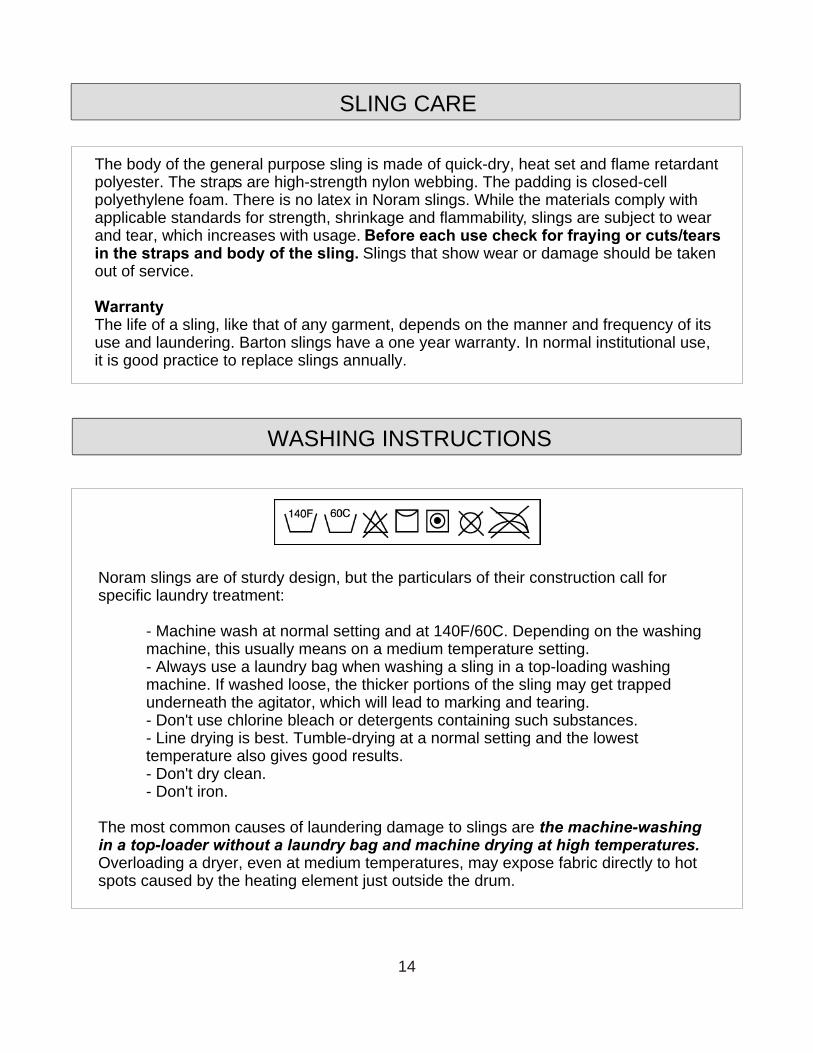
The body of the general purpose sling is made of quick-dry, heat set and flame retardant polyester. The straps are high-strength nylon webbing. The padding is closed-cell polyethylene foam. There is no latex in Noram slings. While the materials comply with applicable standards for strength, shrinkage and flammability, slings are subject to wear and tear, which increases with usage. Before each use check for fraying or cuts/tears in the straps and body of the sling. Slings that show wear or damage should be taken out of service.
WarrantyThe life of a sling, like that of any garment, depends on the manner and frequency of its use and laundering. Barton slings have a one year warranty. In normal institutional use, it is good practice to replace slings annually.
Noram slings are of sturdy design, but the particulars of their construction call for specific laundry treatment:
- Machine wash at normal setting and at 140F/60C. Depending on the washing machine, this usually means on a medium temperature setting.- Always use a laundry bag when washing a sling in a top-loading washing machine. If washed loose, the thicker portions of the sling may get trapped underneath the agitator, which will lead to marking and tearing.- Don't use chlorine bleach or detergents containing such substances.- Line drying is best. Tumble-drying at a normal setting and the lowest temperature also gives good results.- Don't dry clean.- Don't iron.
The most common causes of laundering damage to slings are the machine-washing in a top-loader without a laundry bag and machine drying at high temperatures. Overloading a dryer, even at medium temperatures, may expose fabric directly to hot spots caused by the heating element just outside the drum.
14
TRANSFERS
CHAIR TO BED TRANSFER
1. Choose the appropriate sling for your resident and place it under them. (For more information on using slings please see the Slings section of this manual).
2. Adjust the legs of the Ready Care Lift to straddle the chair. Use your left foot to push the left pedal of the leg adjustment to widen the legs to the correct width. The leg assembly has three width positions.
3. Lower the lift arm assembly by using the hand control, to enable you to attach the sling to the hanger.
4. Raise the resident by using the hand control.
5. Transfer the resident to the bed and raise them high enough to clear the bed.
6. Position the resident over the centre of the bed and lower them using the hand control.
7. Unhook the sling and move the Ready Care Lift away.
8. Turn the resident on their side and turn the sling towards their back. Turn the resident onto their other side and remove the sling.
15
TRANSFERS
BED TO CHAIR TRANSFER
1. Choose the appropriate sling for your resident.
2. Turn the resident on their side and position the sling at their back. Spread one side of the sling out and turn the resident onto it and over further onto their side. Spread the other half of the sling out and turn the resident onto their back.
3. Position the legs of the sling under the residents legs.
4. Position the Ready Care Lift over the resident and lower the lift arm assembly, using the hand control, low enough to allow you to connect the sling to the hanger.
5. Raise the resident off the bed using the hand control.
6. Move the Ready Care Lift with resident and position over the chair. Position the resident so as they are lowered they will be correctly positioned to be seated in the chair.
7. At this point, if lowering into a wheelchair, lock the wheels of the chair. You may also want to lock the back wheels of the Ready Care Lift. Slowly start to lower the resident observing their descent and the position they are achieving in the chair. You may want to adjust accordingly if the position is not correct.
To position the resident straight in the chair, pull on the sling loop located at the residents back as you are lowering them into the chair.
8. Continue to lower. If the wheelchair tilts back slightly, it is normal. It will correct itself when the resident is completely in the chair.
9. Once the resident is fully seated, lower the lift arm assembly to enable you to remove the sling from the hanger.
10. Lift the residents legs in order to remove the leg sections of the sling.
11. Lean the resident forward and remove the sling from behind them.
**NOTE**Spreader bars can be used for very large residents or for lifting from the floor.
16
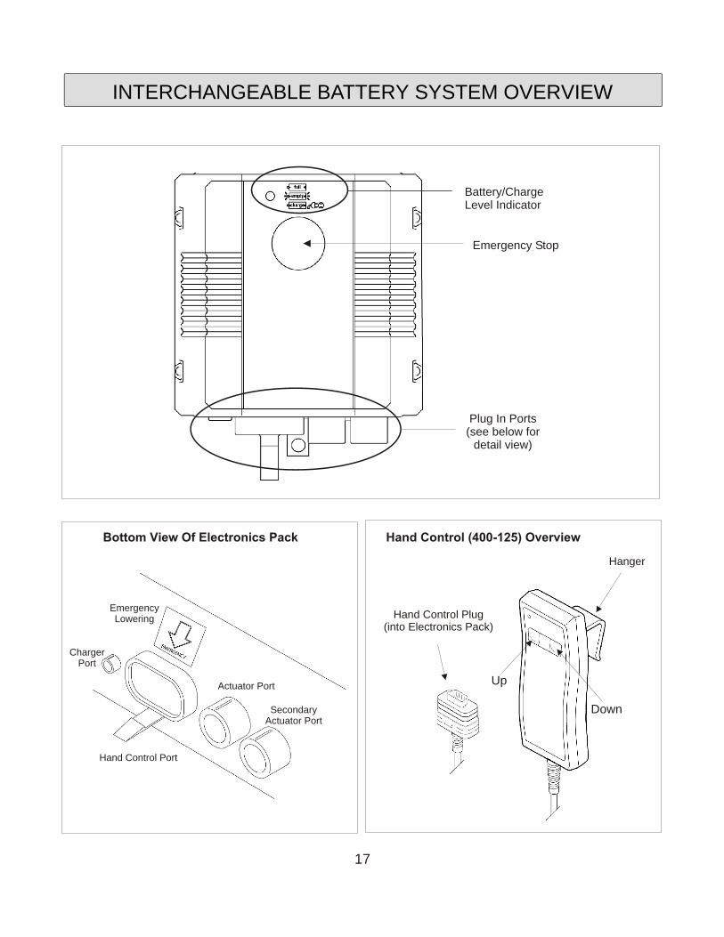
ChargerPort
Actuator Port
SecondaryActuator Port
Hand Control Port
EmergencyLowering
Emergency Stop
Battery/ChargeLevel Indicator
Plug In Ports(see below for
detail view)
INTERCHANGEABLE BATTERY SYSTEM OVERVIEW
Bottom View Of Electronics Pack
Down
Up
Hanger
Hand Control Plug(into Electronics Pack)
Hand Control (400-125) Overview
17
1. It is highly recommended that the batteries be fully charged on a daily basis. This action will greatly extend the life to the battery.
2. The Battery Pack may be charged while on the lift by inserting the charger plug into the charger port on the bottom of the Electronics Pack (see Electronics Pack Bottom View on page 14). This is the recommended method of charging.
3. The Battery Pack may also be charged using a separate wall-mounted charging station (optional). The charger is plugged into the charging station. The Battery is removed from the Ready Care Lift (see Placing and Removing the Battery Pack on page 17) and placed into the charging station.
4. The LED Battery Level Indicator on the front of the electronics pack (see Interchangeable Battery System Overview on page 14) indicates the battery charge level. When the yellow light begins to flash, it indicates that the battery requires charging. In addition to the LED, an audible signal (beep) sounds when the battery level is low and in need of a charge. Please note, even on low battery power, the Ready Care Lift can still be safely operated two more times before recharging.
When charging the battery, the yellow light will illuminate, indicating the battery is charging. When the yellow light changes to green, the battery is fully charged.
5. The Electric Hand Control operates the raising and lowering of the lift arm assembly. The hand control should remain connected to the electronics pack. Should you find it necessary to remove the hand control, unplug it from the hand control port on the bottom of the electronics pack (see Electronics Pack Bottom View on page 14). There is a plastic tab that locks the hand control in place. Remember to push the tab clear of the plug before disconnecting the hand control.
6. There is a red Emergency Stop Switch located on the front of the electronics pack. This will disable the lift in case of a malfunction with the electronics. Push the red button to shut off power to the lifter. Turn the red button in the direction of the arrows (clockwise) to return power to the lifter.
7. The Emergency Lowering switch ensures that the lifter can be lowered safely should the hand control malfunction. The emergency lowering switch is a yellow membrane switch, located on the bottom of the electronics pack (see Electronics Pack Bottom View on page 14).
INTERCHANGEABLE BATTERY SYSTEM
18
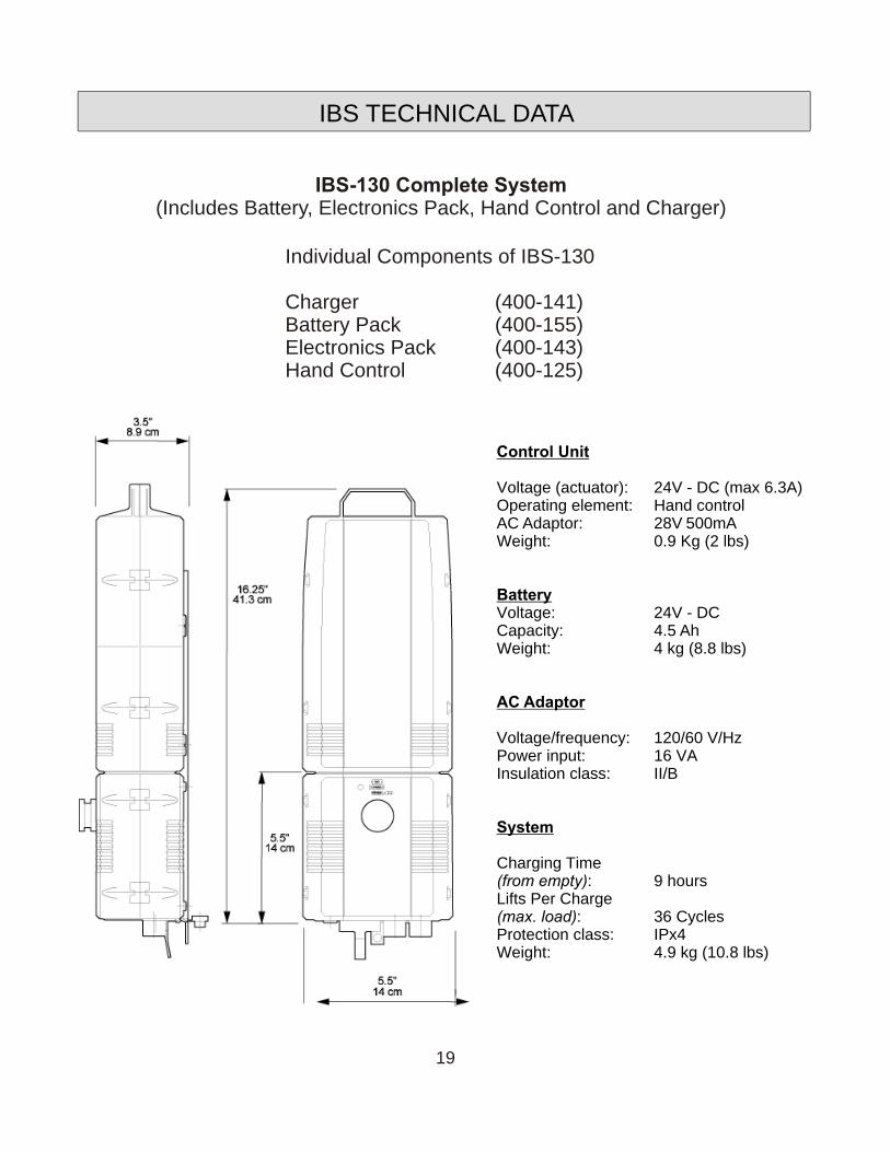
Control Unit
Voltage (actuator): 24V - DC (max 6.3A)Operating element: Hand controlAC Adaptor: 28V 500mAWeight: 0.9 Kg (2 lbs)
BatteryVoltage: 24V - DCCapacity: 4.5 AhWeight: 4 kg (8.8 lbs)
AC Adaptor
Voltage/frequency: 120/60 V/HzPower input: 16 VAInsulation class: II/B
System
Charging Time(from empty): 9 hours Lifts Per Charge(max. load): 36 CyclesProtection class: IPx4Weight: 4.9 kg (10.8 lbs)
IBS TECHNICAL DATA
Individual Components of IBS-130
Charger (400-141)Battery Pack (400-155)Electronics Pack (400-143)Hand Control (400-125)
IBS-130 Complete System(Includes Battery, Electronics Pack, Hand Control and Charger)
19
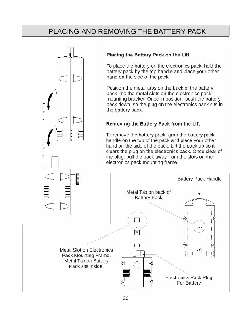
Placing the Battery Pack on the Lift
To place the battery on the electronics pack, hold the battery pack by the top handle and place your other hand on the side of the pack.
Position the metal tabs on the back of the battery pack into the metal slots on the electronics pack mounting bracket. Once in position, push the battery pack down, so the plug on the electronics pack sits in the battery pack.
Removing the Battery Pack from the Lift
To remove the battery pack, grab the battery pack handle on the top of the pack and place your other hand on the side of the pack. Lift the pack up so it clears the plug on the electronics pack. Once clear of the plug, pull the pack away from the slots on the electronics pack mounting frame.
Metal Tab on back ofBattery Pack
Metal Slot on ElectronicsPack Mounting Frame.Metal Tab on Battery
Pack sits inside.
Battery Pack Handle
Electronics Pack PlugFor Battery
PLACING AND REMOVING THE BATTERY PACK
20
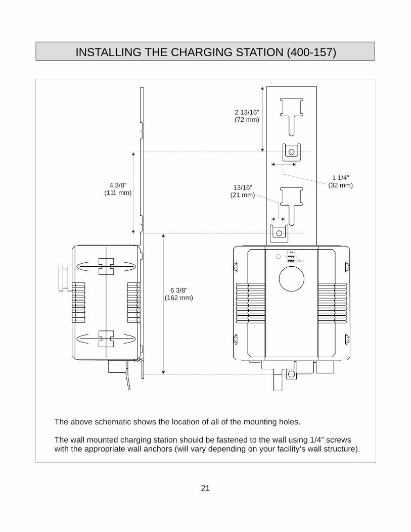
INSTALLING THE CHARGING STATION (400-157)
6 3/8”(162 mm)
13/16”(21 mm)
4 3/8”(111 mm)
2 13/16”(72 mm)
The above schematic shows the location of all of the mounting holes.
The wall mounted charging station should be fastened to the wall using 1/4” screws with the appropriate wall anchors (will vary depending on your facility’s wall structure).
1 1/4”(32 mm)
21
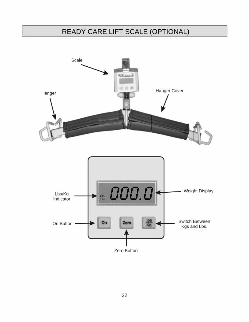
Lbs/KgIndicator
On Button
Zero Button
Switch BetweenKgs and Lbs.
Weight Display
Scale
HangerHanger Cover
READY CARE LIFT SCALE (OPTIONAL)
22

Parts required to install:
1 - 3/8" N.C. x 2" hex head bolt 1 - 3/8" N.C. nylock nut2 - 3/8" x 1/2" buttite spacer
1. Slide lift arm end cover up onto the lift arm and remove the nut and bolt which secures the hanger and remove the hanger.
2. Insert one buttite spacer onto the 3/8" N.C. hex head bolt.
3. Using the 3/8" N.C. hex head bolt, guide the 1/2" buttite spacer inside the lift arm assembly.
4. Place the safety lock cover (#5) onto the hanger scale assembly hook. The safety lock cover hole should be at the top of the scale hook.
5. With the 3/8" N.C. hex head bolt and buttite spacer through the one side of the 1/2" hole on the boom channel insert the scale hanger assembly inside the boom channel.
6. Now insert the 3/8" N.C. hex head bolt through the safety lock and scale hook. Expose only enough of the bolt to insert the second buttite spacer.
7. After the second buttite spacer is in place, insert the 3/8" N.C. hex head boltthrough the 1/2" hole in the boom channel. Both buttite spacers should be flush with the outside surfaces of the lift arm assembly.
8. Attach the 3/8” N.C. nylock nut to the hex head bolt, tighten the nylock nut until one thread extends past the end of the hex nut.DO NOT OVER TIGHTEN!
SCALE ATTACHMENT (OPTIONAL)
23
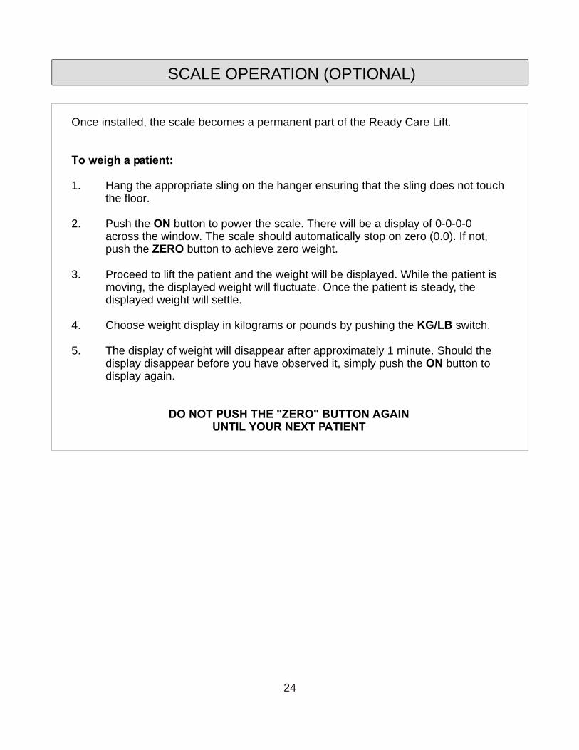
Once installed, the scale becomes a permanent part of the Ready Care Lift.
To weigh a patient:
1. Hang the appropriate sling on the hanger ensuring that the sling does not touch the floor.
2. Push the ON button to power the scale. There will be a display of 0-0-0-0 across the window. The scale should automatically stop on zero (0.0). If not, push the ZERO button to achieve zero weight.
3. Proceed to lift the patient and the weight will be displayed. While the patient is moving, the displayed weight will fluctuate. Once the patient is steady, the displayed weight will settle.
4. Choose weight display in kilograms or pounds by pushing the KG/LB switch.
5. The display of weight will disappear after approximately 1 minute. Should the display disappear before you have observed it, simply push the ON button to display again.
DO NOT PUSH THE "ZERO" BUTTON AGAINUNTIL YOUR NEXT PATIENT
SCALE OPERATION (OPTIONAL)
24
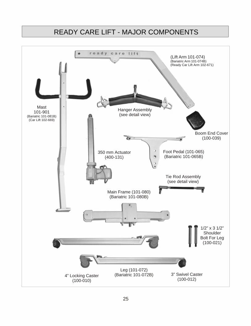
Mast101-901
(Bariatric 101-081B)(Car Lift 102-669)
1/2” x 3 1/2”Shoulder
Bolt For Leg(100-021)
Hanger Assembly(see detail view)
Foot Pedal (101-065)(Bariatric 101-065B)
(Lift Arm 101-074)(Bariatric Arm 101-074B)(Ready Car Lift Arm 102-671)
Boom End Cover(100-039)
350 mm Actuator(400-131)
Tie Rod Assembly(see detail view)
Main Frame (101-080)(Bariatric 101-080B)
Leg (101-072)(Bariatric 101-072B)4” Locking Caster
(100-010)
3” Swivel Caster(100-012)
READY CARE LIFT - MAJOR COMPONENTS
25
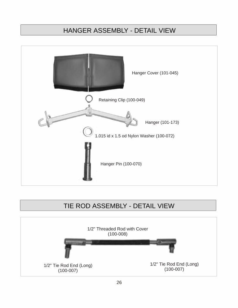
Hanger Cover (101-045)
Retaining Clip (100-049)
Hanger (101-173)
1.015 id x 1.5 od Nylon Washer (100-072)
Hanger Pin (100-070)
1/2" Tie Rod End (Long)(100-007)
1/2" Tie Rod End (Long)(100-007)
1/2" Threaded Rod with Cover(100-008)
HANGER ASSEMBLY - DETAIL VIEW
TIE ROD ASSEMBLY - DETAIL VIEW
26
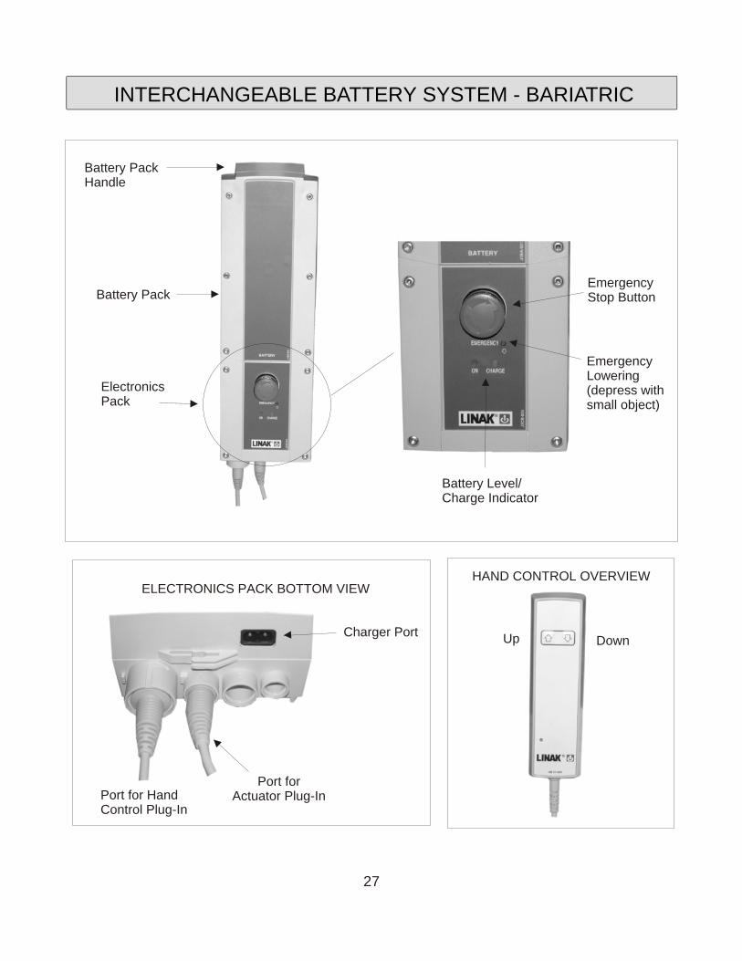
Battery Pack
Battery PackHandle
ElectronicsPack
Battery Level/Charge Indicator
EmergencyStop Button
Up Down
HAND CONTROL OVERVIEW
Charger Port
Port for HandControl Plug-In
Port forActuator Plug-In
ELECTRONICS PACK BOTTOM VIEW
EmergencyLowering (depress withsmall object)
INTERCHANGEABLE BATTERY SYSTEM - BARIATRIC
27
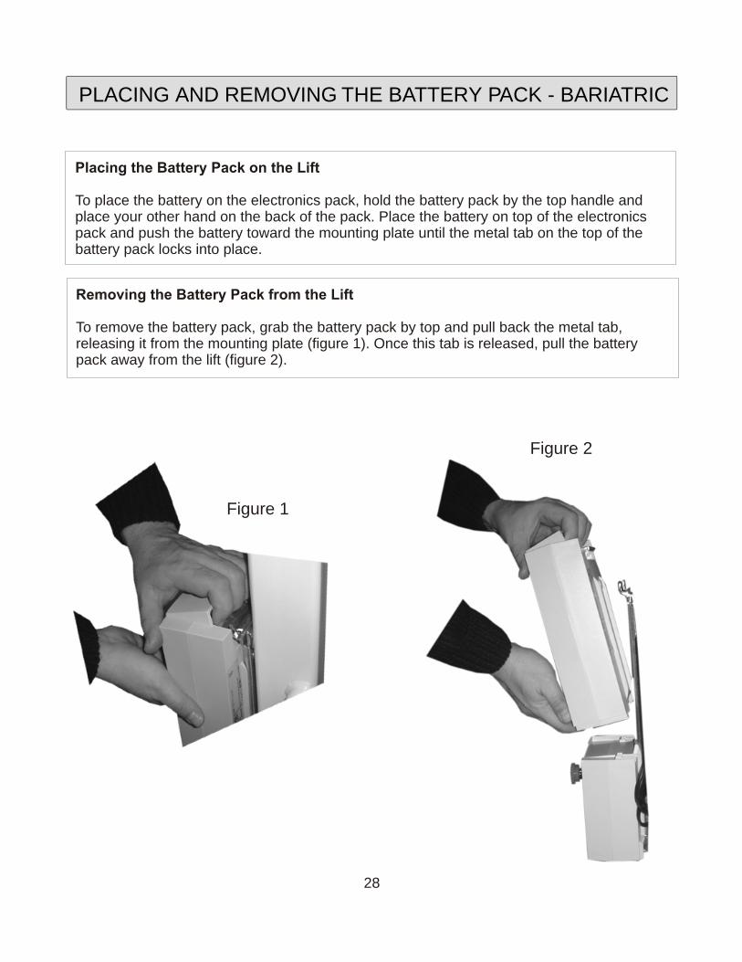
Placing the Battery Pack on the Lift
To place the battery on the electronics pack, hold the battery pack by the top handle and place your other hand on the back of the pack. Place the battery on top of the electronics pack and push the battery toward the mounting plate until the metal tab on the top of the battery pack locks into place.
Removing the Battery Pack from the Lift
To remove the battery pack, grab the battery pack by top and pull back the metal tab, releasing it from the mounting plate (figure 1). Once this tab is released, pull the battery pack away from the lift (figure 2).
Figure 1
Figure 2
PLACING AND REMOVING THE BATTERY PACK - BARIATRIC
28
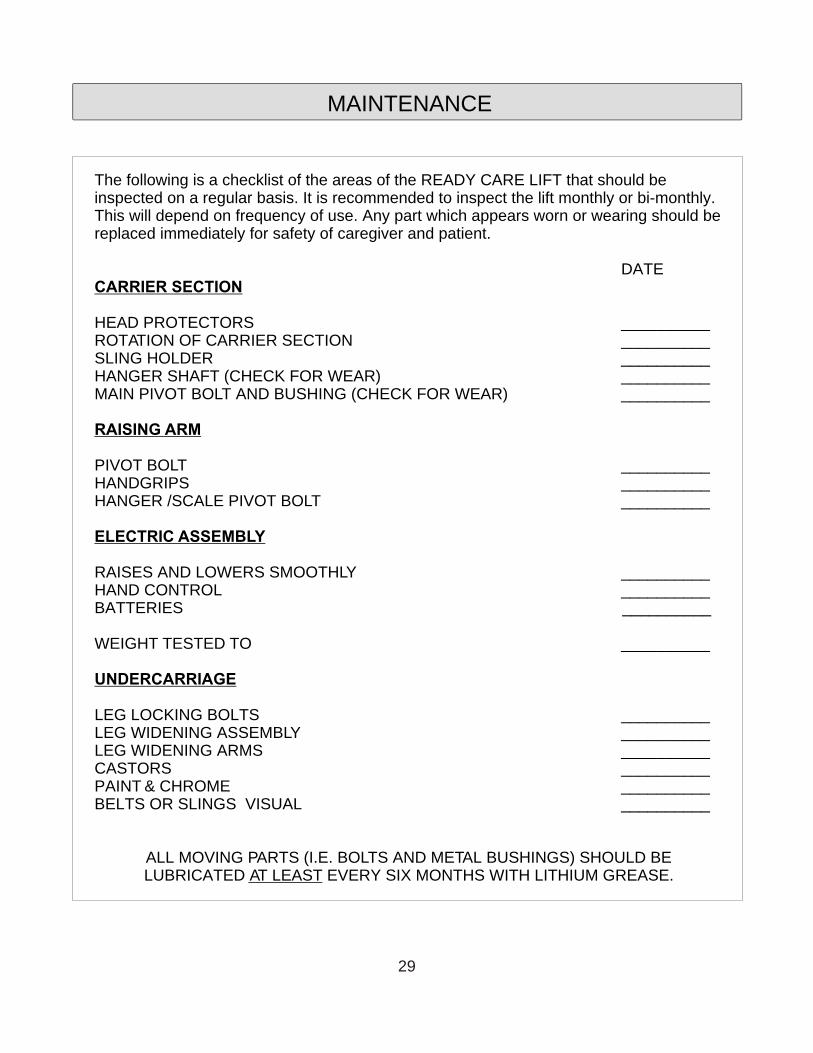
The following is a checklist of the areas of the READY CARE LIFT that should be inspected on a regular basis. It is recommended to inspect the lift monthly or bi-monthly. This will depend on frequency of use. Any part which appears worn or wearing should be replaced immediately for safety of caregiver and patient.
DATECARRIER SECTION
HEAD PROTECTORS __________ROTATION OF CARRIER SECTION __________SLING HOLDER __________HANGER SHAFT (CHECK FOR WEAR) __________MAIN PIVOT BOLT AND BUSHING (CHECK FOR WEAR) __________
RAISING ARM
PIVOT BOLT __________HANDGRIPS __________HANGER /SCALE PIVOT BOLT __________
ELECTRIC ASSEMBLY
RAISES AND LOWERS SMOOTHLY __________HAND CONTROL __________BATTERIES __________
WEIGHT TESTED TO __________
UNDERCARRIAGE
LEG LOCKING BOLTS __________LEG WIDENING ASSEMBLY __________LEG WIDENING ARMS __________CASTORS __________PAINT & CHROME __________BELTS OR SLINGS VISUAL __________
ALL MOVING PARTS (I.E. BOLTS AND METAL BUSHINGS) SHOULD BE LUBRICATED AT LEAST EVERY SIX MONTHS WITH LITHIUM GREASE.
MAINTENANCE
29
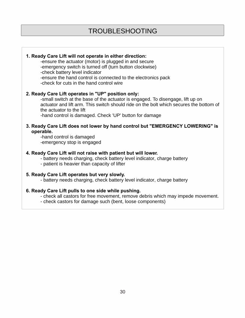
TROUBLESHOOTING
1. Ready Care Lift will not operate in either direction:-ensure the actuator (motor) is plugged in and secure-emergency switch is turned off (turn button clockwise)-check battery level indicator-ensure the hand control is connected to the electronics pack-check for cuts in the hand control wire
2. Ready Care Lift operates in "UP" position only:-small switch at the base of the actuator is engaged. To disengage, lift up on actuator and lift arm. This switch should ride on the bolt which secures the bottom of the actuator to the lift-hand control is damaged. Check 'UP' button for damage
3. Ready Care Lift does not lower by hand control but "EMERGENCY LOWERING" is operable.
-hand control is damaged-emergency stop is engaged
4. Ready Care Lift will not raise with patient but will lower.- battery needs charging, check battery level indicator, charge battery- patient is heavier than capacity of lifter
5. Ready Care Lift operates but very slowly.- battery needs charging, check battery level indicator, charge battery
6. Ready Care Lift pulls to one side while pushing.- check all castors for free movement, remove debris which may impede movement.- check castors for damage such (bent, loose components)
30

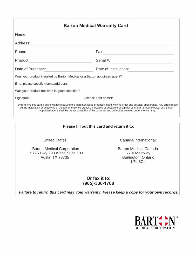
Please fill out this card and return it to:
Or fax it to:(905)-336-1708
Failure to return this card may void warranty. Please keep a copy for your own records.
United States:
Barton Medical Corporation5725 Hwy 290 West, Suite 103
Austin TX 78735
Canada/International:
Barton Medical Canada5510 Mainway
Burlington, OntarioL7L 6C4
Barton Medical Warranty Card
Name:
Address:
Phone: Fax:
Product: Serial #:
Date of Purchase: Date of Installation:
Was your product installed by Barton Medical or a Barton appointed agent?
If no, please specify (name/address):
Was your product received in good condition?
Signature: (please print name):
By returning this card, I acknowledge receiving the aforementioned product in good working order and physical appearance. Any errors made during installation or unpacking of the aforementioned product, if installed or unpacked by a party other than Barton Medical or a Barton
appointed agent, shall be the responsibility of the customer and will not be covered under the warranty.