Embed Size (px)
Citation preview
SPRITE and BIGFOOT DESKTOP CNC MACHINEKIT ASSEMBLY INSTRUCTIONS
README FIRST:
Thank you for purchasing your MyDIYCNC Desktop CNC Machine Kit. We hope this versatileand innovative machine brings you many hours of productive work and enjoyment.
Login to your MyDIYCNC account on our website and from the Support > Downloads andthe Support > Resources areas download the Comprehensive Plans & Manual (CP&M)eBook, the Anti-backlash & Motor Couplings Assembly instructions and the Electronics &Wiring Instructions. If you purchased the optional limit switches kit, you will also need todownload the Limit Switch Assembly Instructions.
While these instructions apply to both our Sprite and BigFoot models, the instructionsdepict a Sprite build. Assembly of a BigFoot Desktop CNC Machine Kit will be identical.
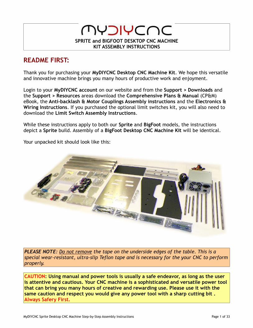
Your unpacked kit should look like this:
PLEASE NOTE: Do not remove the tape on the underside edges of the table. This is aspecial wear-resistant, ultra-slip Teflon tape and is necessary for the your CNC to performproperly.
CAUTION: Using manual and power tools is usually a safe endeavor, as long as the useris attentive and cautious. Your CNC machine is a sophisticated and versatile power toolthat can bring you many hours of creative and rewarding use. Please use it with thesame caution and respect you would give any power tool with a sharp cutting bit .Always Safery First.
MyDIYCNC Sprite Desktop CNC Machine Step-by-Step Assembly Instructions Page 1 of 33
BEFORE YOU BEGIN:
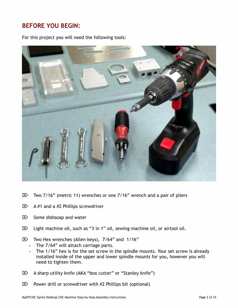
For this project you will need the following tools:
Two 7/16” (metric 11) wrenches or one 7/16” wrench and a pair of pliers
A #1 and a #2 Phillips screwdriver
Some dishsoap and water
Light machine oil, such as “3 in 1” oil, sewing machine oil, or airtool oil.
Two Hex wrenches (Allen keys), 7/64” and 1/16”• The 7/64” will attach carriage parts.• The 1/16” hex is for the set screw in the spindle mounts. Your set screw is already
installed inside of the upper and lower spindle mounts for you, however you willneed to tighten them.
A sharp utility knife (AKA “box cutter” or “Stanley knife”)
Power drill or screwdriver with #2 Phillips bit (optional)
MyDIYCNC Sprite Desktop CNC Machine Step-by-Step Assembly Instructions Page 2 of 33
PREPARATION:
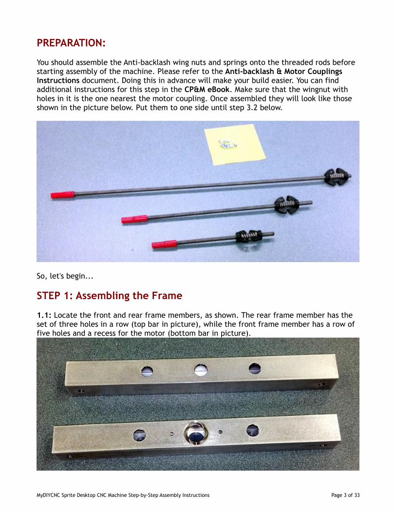
You should assemble the Anti-backlash wing nuts and springs onto the threaded rods beforestarting assembly of the machine. Please refer to the Anti-backlash & Motor CouplingsInstructions document. Doing this in advance will make your build easier. You can findadditional instructions for this step in the CP&M eBook. Make sure that the wingnut withholes in it is the one nearest the motor coupling. Once assembled they will look like thoseshown in the picture below. Put them to one side until step 3.2 below.
So, let's begin...
STEP 1: Assembling the Frame
1.1: Locate the front and rear frame members, as shown. The rear frame member has theset of three holes in a row (top bar in picture), while the front frame member has a row offive holes and a recess for the motor (bottom bar in picture).
MyDIYCNC Sprite Desktop CNC Machine Step-by-Step Assembly Instructions Page 3 of 33
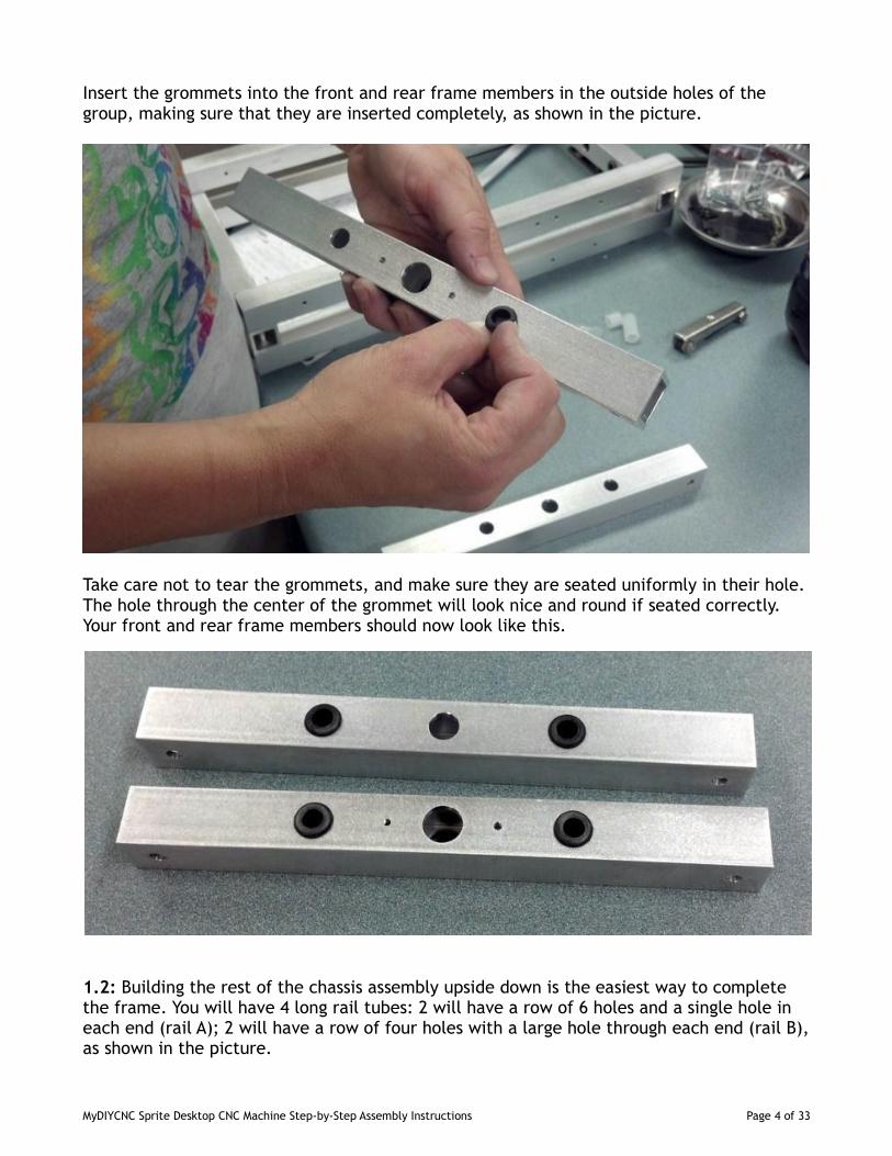
Insert the grommets into the front and rear frame members in the outside holes of thegroup, making sure that they are inserted completely, as shown in the picture.
Take care not to tear the grommets, and make sure they are seated uniformly in their hole.The hole through the center of the grommet will look nice and round if seated correctly.Your front and rear frame members should now look like this.
1.2: Building the rest of the chassis assembly upside down is the easiest way to completethe frame. You will have 4 long rail tubes: 2 will have a row of 6 holes and a single hole ineach end (rail A); 2 will have a row of four holes with a large hole through each end (rail B),as shown in the picture.
MyDIYCNC Sprite Desktop CNC Machine Step-by-Step Assembly Instructions Page 4 of 33
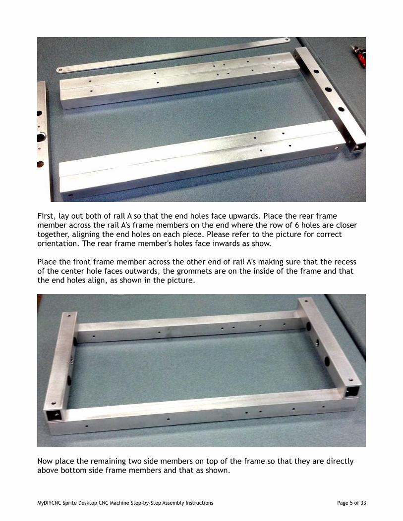
First, lay out both of rail A so that the end holes face upwards. Place the rear framemember across the rail A's frame members on the end where the row of 6 holes are closertogether, aligning the end holes on each piece. Please refer to the picture for correctorientation. The rear frame member's holes face inwards as show.
Place the front frame member across the other end of rail A's making sure that the recessof the center hole faces outwards, the grommets are on the inside of the frame and thatthe end holes align, as shown in the picture.
Now place the remaining two side members on top of the frame so that they are directlyabove bottom side frame members and that as shown.
MyDIYCNC Sprite Desktop CNC Machine Step-by-Step Assembly Instructions Page 5 of 33
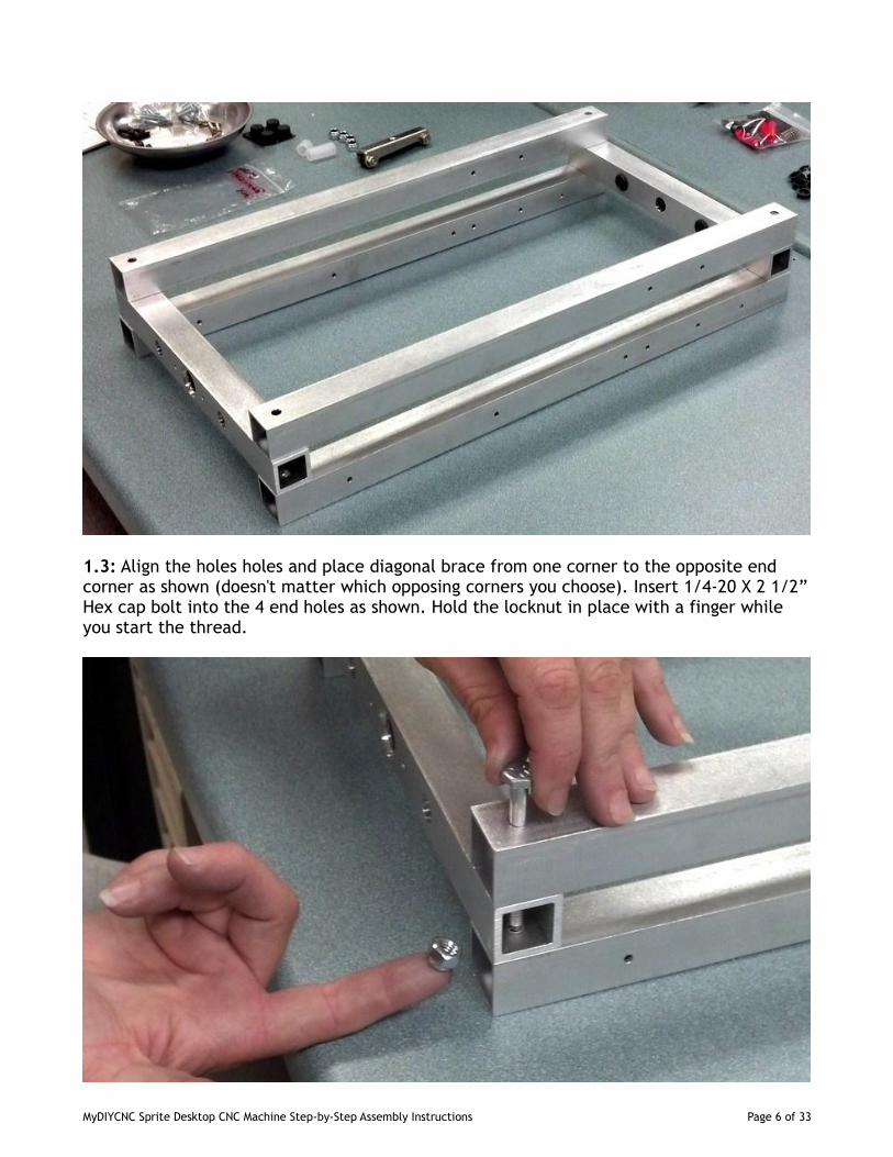
1.3: Align the holes holes and place diagonal brace from one corner to the opposite endcorner as shown (doesn't matter which opposing corners you choose). Insert 1/4-20 X 2 1/2”Hex cap bolt into the 4 end holes as shown. Hold the locknut in place with a finger whileyou start the thread.
MyDIYCNC Sprite Desktop CNC Machine Step-by-Step Assembly Instructions Page 6 of 33
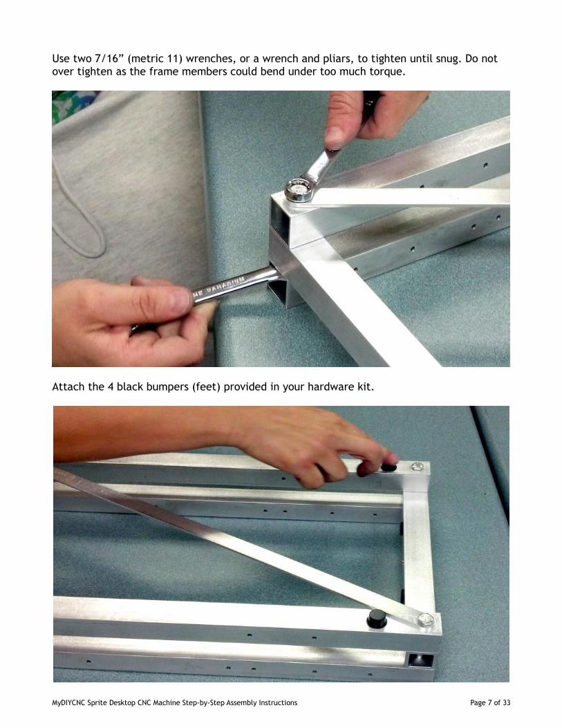
Use two 7/16” (metric 11) wrenches, or a wrench and pliars, to tighten until snug. Do notover tighten as the frame members could bend under too much torque.
Attach the 4 black bumpers (feet) provided in your hardware kit.
MyDIYCNC Sprite Desktop CNC Machine Step-by-Step Assembly Instructions Page 7 of 33
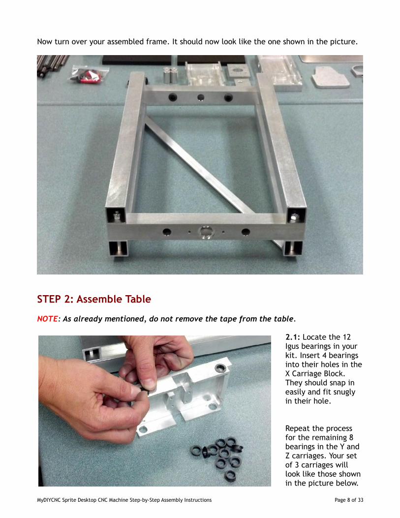
Now turn over your assembled frame. It should now look like the one shown in the picture.
STEP 2: Assemble Table
NOTE: As already mentioned, do not remove the tape from the table.
2.1: Locate the 12Igus bearings in yourkit. Insert 4 bearingsinto their holes in theX Carriage Block.They should snap ineasily and fit snuglyin their hole.
Repeat the processfor the remaining 8bearings in the Y andZ carriages. Your setof 3 carriages willlook like those shownin the picture below.
MyDIYCNC Sprite Desktop CNC Machine Step-by-Step Assembly Instructions Page 8 of 33
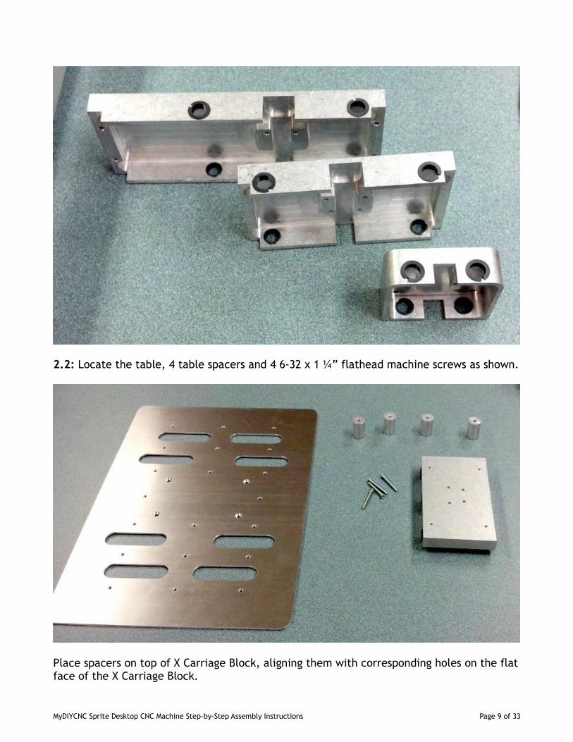
2.2: Locate the table, 4 table spacers and 4 6-32 x 1 ¼” flathead machine screws as shown.
Place spacers on top of X Carriage Block, aligning them with corresponding holes on the flatface of the X Carriage Block.
MyDIYCNC Sprite Desktop CNC Machine Step-by-Step Assembly Instructions Page 9 of 33
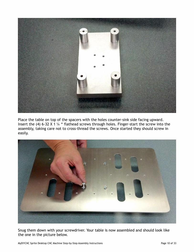
Place the table on top of the spacers with the holes counter-sink side facing upward.Insert the (4) 6-32 X 1 ¼ “ flathead screws through holes. Finger-start the screw into theassembly, taking care not to cross-thread the screws. Once started they should screw ineasily.
Snug them down with your screwdriver. Your table is now assembled and should look likethe one in the picture below.
MyDIYCNC Sprite Desktop CNC Machine Step-by-Step Assembly Instructions Page 10 of 33
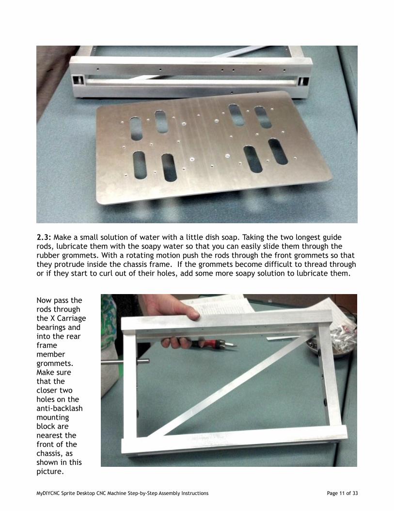
2.3: Make a small solution of water with a little dish soap. Taking the two longest guiderods, lubricate them with the soapy water so that you can easily slide them through therubber grommets. With a rotating motion push the rods through the front grommets so thatthey protrude inside the chassis frame. If the grommets become difficult to thread throughor if they start to curl out of their holes, add some more soapy solution to lubricate them.
Now pass therods throughthe X Carriagebearings andinto the rearframemembergrommets.Make surethat thecloser twoholes on theanti-backlashmountingblock arenearest thefront of thechassis, asshown in thispicture.
MyDIYCNC Sprite Desktop CNC Machine Step-by-Step Assembly Instructions Page 11 of 33
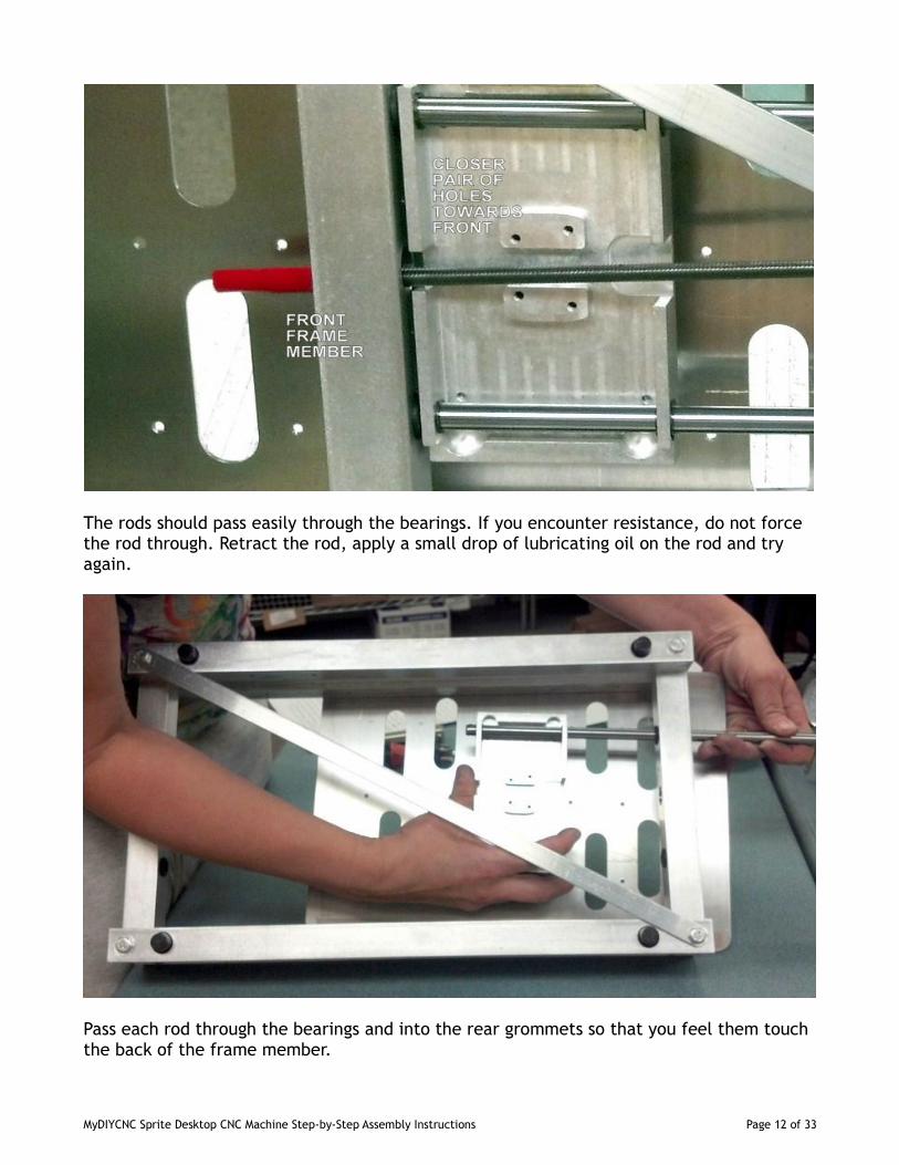
The rods should pass easily through the bearings. If you encounter resistance, do not forcethe rod through. Retract the rod, apply a small drop of lubricating oil on the rod and tryagain.
Pass each rod through the bearings and into the rear grommets so that you feel them touchthe back of the frame member.
MyDIYCNC Sprite Desktop CNC Machine Step-by-Step Assembly Instructions Page 12 of 33
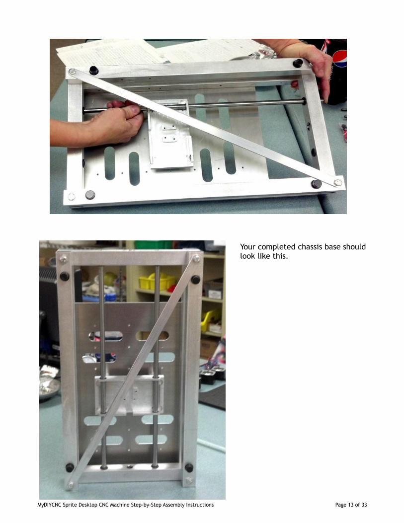
Your completed chassis base shouldlook like this.
MyDIYCNC Sprite Desktop CNC Machine Step-by-Step Assembly Instructions Page 13 of 33
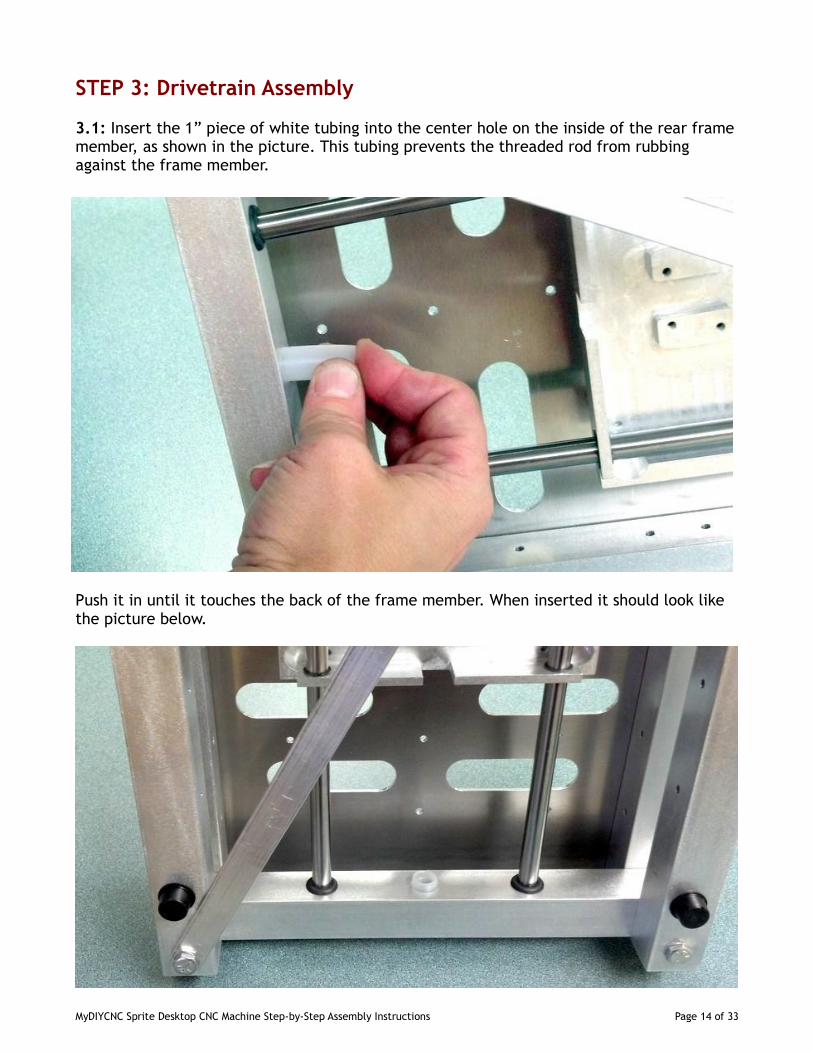
STEP 3: Drivetrain Assembly
3.1: Insert the 1” piece of white tubing into the center hole on the inside of the rear framemember, as shown in the picture. This tubing prevents the threaded rod from rubbingagainst the frame member.
Push it in until it touches the back of the frame member. When inserted it should look likethe picture below.
MyDIYCNC Sprite Desktop CNC Machine Step-by-Step Assembly Instructions Page 14 of 33
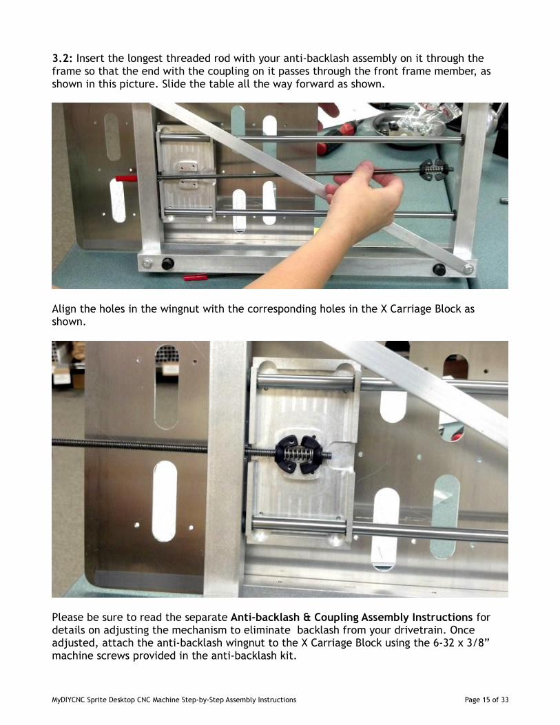
3.2: Insert the longest threaded rod with your anti-backlash assembly on it through theframe so that the end with the coupling on it passes through the front frame member, asshown in this picture. Slide the table all the way forward as shown.
Align the holes in the wingnut with the corresponding holes in the X Carriage Block asshown.
Please be sure to read the separate Anti-backlash & Coupling Assembly Instructions fordetails on adjusting the mechanism to eliminate backlash from your drivetrain. Onceadjusted, attach the anti-backlash wingnut to the X Carriage Block using the 6-32 x 3/8”machine screws provided in the anti-backlash kit.
MyDIYCNC Sprite Desktop CNC Machine Step-by-Step Assembly Instructions Page 15 of 33
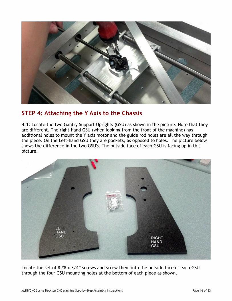
STEP 4: Attaching the Y Axis to the Chassis
4.1: Locate the two Gantry Support Uprights (GSU) as shown in the picture. Note that theyare different. The right-hand GSU (when looking from the front of the machine) hasadditional holes to mount the Y axis motor and the guide rod holes are all the way throughthe piece. On the Left-hand GSU they are pockets, as opposed to holes. The picture belowshows the difference in the two GSU's. The outside face of each GSU is facing up in thispicture.
Locate the set of 8 #8 x 3/4” screws and screw them into the outside face of each GSUthrough the four GSU mounting holes at the bottom of each piece as shown.
MyDIYCNC Sprite Desktop CNC Machine Step-by-Step Assembly Instructions Page 16 of 33
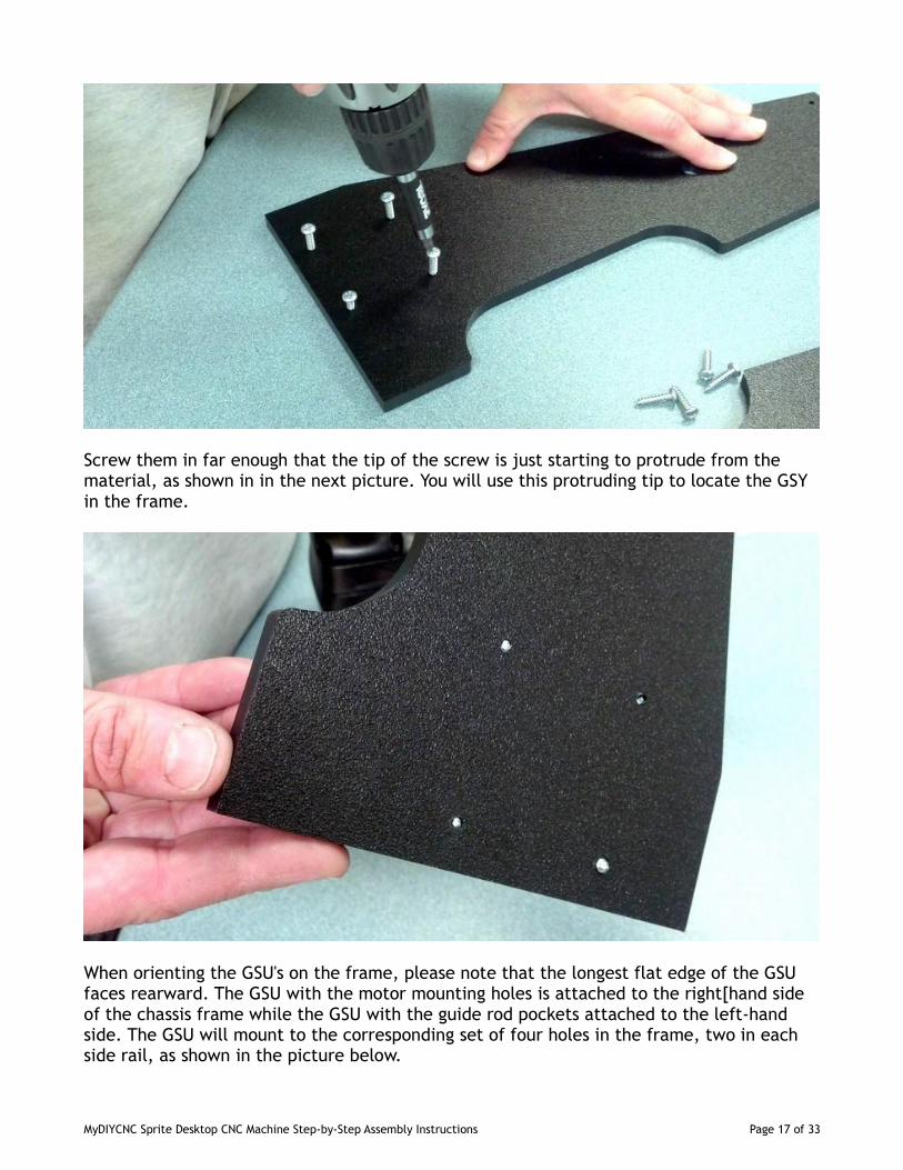
Screw them in far enough that the tip of the screw is just starting to protrude from thematerial, as shown in in the next picture. You will use this protruding tip to locate the GSYin the frame.
When orienting the GSU's on the frame, please note that the longest flat edge of the GSUfaces rearward. The GSU with the motor mounting holes is attached to the right[hand sideof the chassis frame while the GSU with the guide rod pockets attached to the left-handside. The GSU will mount to the corresponding set of four holes in the frame, two in eachside rail, as shown in the picture below.
MyDIYCNC Sprite Desktop CNC Machine Step-by-Step Assembly Instructions Page 17 of 33
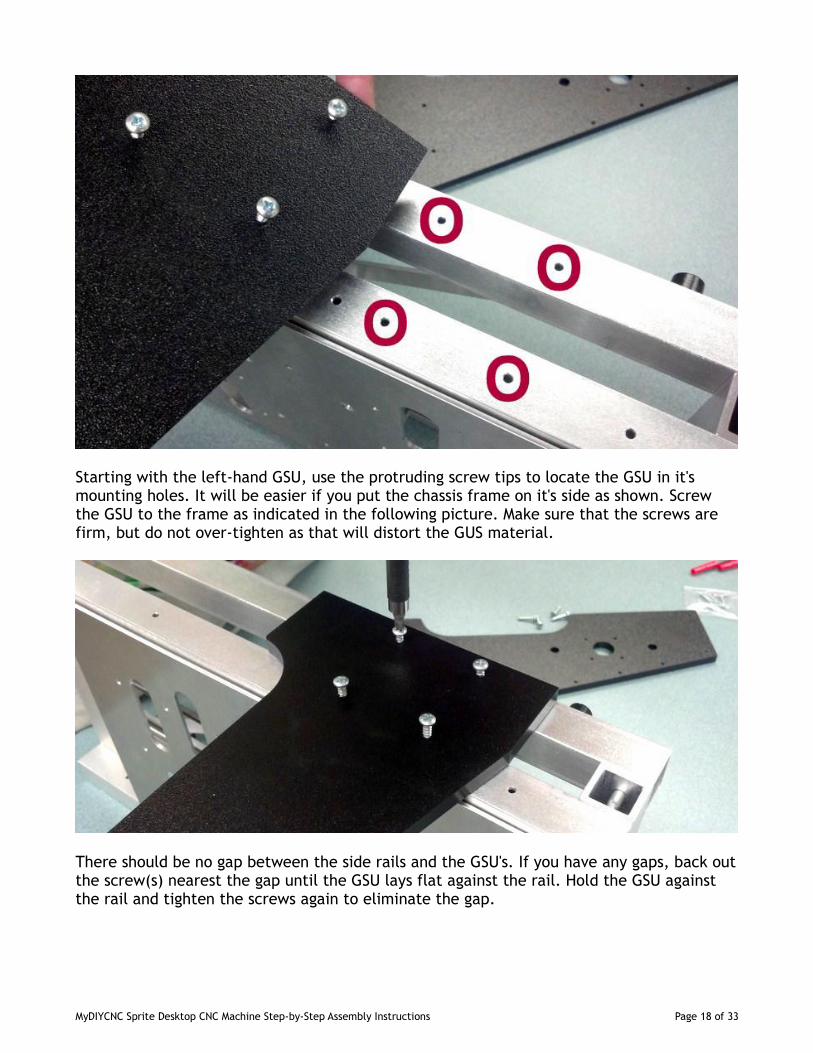
Starting with the left-hand GSU, use the protruding screw tips to locate the GSU in it'smounting holes. It will be easier if you put the chassis frame on it's side as shown. Screwthe GSU to the frame as indicated in the following picture. Make sure that the screws arefirm, but do not over-tighten as that will distort the GUS material.
There should be no gap between the side rails and the GSU's. If you have any gaps, back outthe screw(s) nearest the gap until the GSU lays flat against the rail. Hold the GSU againstthe rail and tighten the screws again to eliminate the gap.
MyDIYCNC Sprite Desktop CNC Machine Step-by-Step Assembly Instructions Page 18 of 33
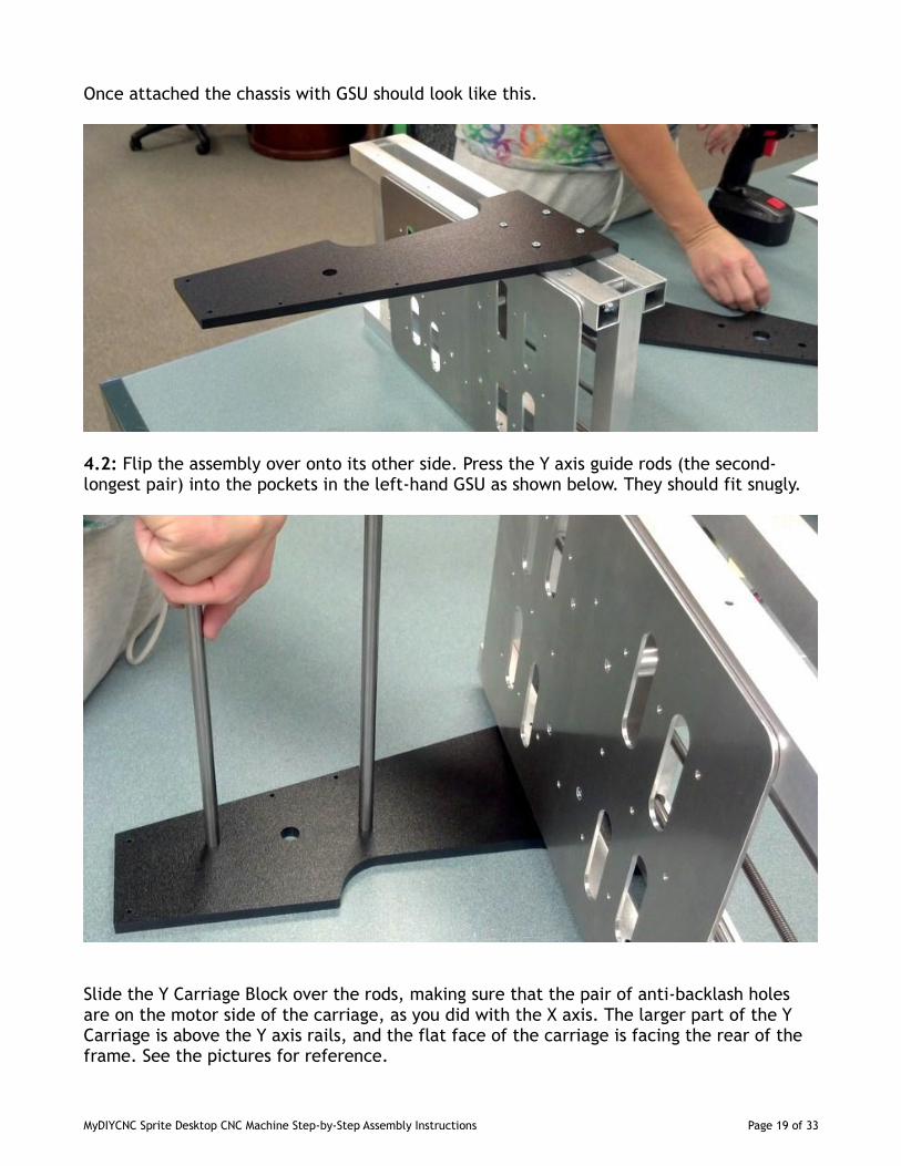
Once attached the chassis with GSU should look like this.
4.2: Flip the assembly over onto its other side. Press the Y axis guide rods (the second-longest pair) into the pockets in the left-hand GSU as shown below. They should fit snugly.
Slide the Y Carriage Block over the rods, making sure that the pair of anti-backlash holesare on the motor side of the carriage, as you did with the X axis. The larger part of the YCarriage is above the Y axis rails, and the flat face of the carriage is facing the rear of theframe. See the pictures for reference.
MyDIYCNC Sprite Desktop CNC Machine Step-by-Step Assembly Instructions Page 19 of 33
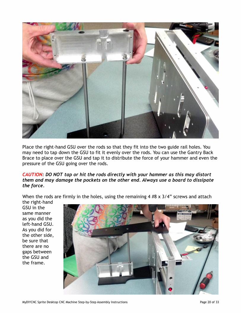
Place the right-hand GSU over the rods so that they fit into the two guide rail holes. Youmay need to tap down the GSU to fit it evenly over the rods. You can use the Gantry BackBrace to place over the GSU and tap it to distribute the force of your hammer and even thepressure of the GSU going over the rods.
CAUTION: DO NOT tap or hit the rods directly with your hammer as this may distortthem and may damage the pockets on the other end. Always use a board to dissipatethe force.
When the rods are firmly in the holes, using the remaining 4 #8 x 3/4” screws and attachthe right-handGSU in thesame manneras you did theleft-hand GSU.As you did forthe other side,be sure thatthere are nogaps betweenthe GSU andthe frame.
MyDIYCNC Sprite Desktop CNC Machine Step-by-Step Assembly Instructions Page 20 of 33
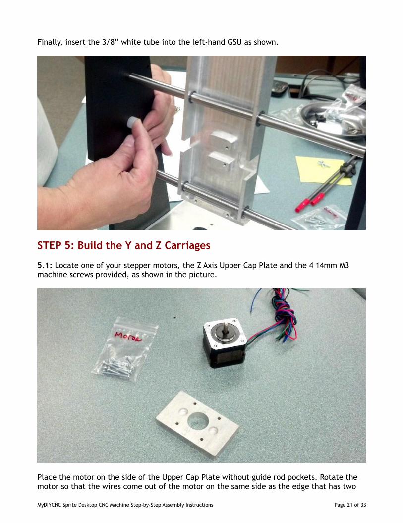
Finally, insert the 3/8” white tube into the left-hand GSU as shown.
STEP 5: Build the Y and Z Carriages
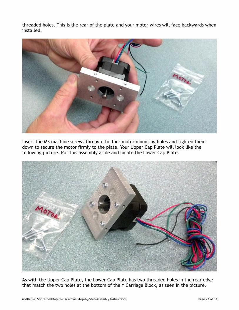
5.1: Locate one of your stepper motors, the Z Axis Upper Cap Plate and the 4 14mm M3machine screws provided, as shown in the picture.
Place the motor on the side of the Upper Cap Plate without guide rod pockets. Rotate themotor so that the wires come out of the motor on the same side as the edge that has two
MyDIYCNC Sprite Desktop CNC Machine Step-by-Step Assembly Instructions Page 21 of 33
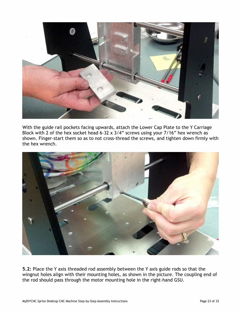
threaded holes. This is the rear of the plate and your motor wires will face backwards wheninstalled.
Insert the M3 machine screws through the four motor mounting holes and tighten themdown to secure the motor firmly to the plate. Your Upper Cap Plate will look like thefollowing picture. Put this assembly aside and locate the Lower Cap Plate.
As with the Upper Cap Plate, the Lower Cap Plate has two threaded holes in the rear edgethat match the two holes at the bottom of the Y Carriage Block, as seen in the picture.
MyDIYCNC Sprite Desktop CNC Machine Step-by-Step Assembly Instructions Page 22 of 33
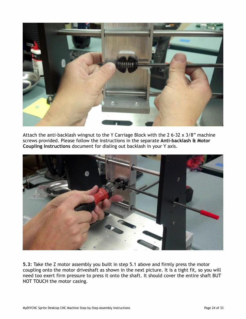
With the guide rail pockets facing upwards, attach the Lower Cap Plate to the Y CarriageBlock with 2 of the hex socket head 6-32 x 3/4” screws using your 7/16” hex wrench asshown. Finger-start them so as to not cross-thread the screws, and tighten down firmly withthe hex wrench.
5.2: Place the Y axis threaded rod assembly between the Y axis guide rods so that thewingnut holes align with their mounting holes, as shown in the picture. The coupling end ofthe rod should pass through the motor mounting hole in the right-hand GSU.
MyDIYCNC Sprite Desktop CNC Machine Step-by-Step Assembly Instructions Page 23 of 33
Attach the anti-backlash wingnut to the Y Carriage Block with the 2 6-32 x 3/8” machinescrews provided. Please follow the instructions in the separate Anti-backlash & MotorCoupling Instructions document for dialing out backlash in your Y axis.
5.3: Take the Z motor assembly you built in step 5.1 above and firmly press the motorcoupling onto the motor driveshaft as shown in the next picture. It is a tight fit, so you willneed too exert firm pressure to press it onto the shaft. It should cover the entire shaft BUTNOT TOUCH the motor casing.
MyDIYCNC Sprite Desktop CNC Machine Step-by-Step Assembly Instructions Page 24 of 33
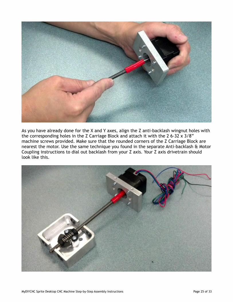
As you have already done for the X and Y axes, align the Z anti-backlash wingnut holes withthe corresponding holes in the Z Carriage Block and attach it with the 2 6-32 x 3/8”machine screws provided. Make sure that the rounded corners of the Z Carriage Block arenearest the motor. Use the same technique you found in the separate Anti-backlash & MotorCoupling instructions to dial out backlash from your Z axis. Your Z axis drivetrain shouldlook like this.
MyDIYCNC Sprite Desktop CNC Machine Step-by-Step Assembly Instructions Page 25 of 33
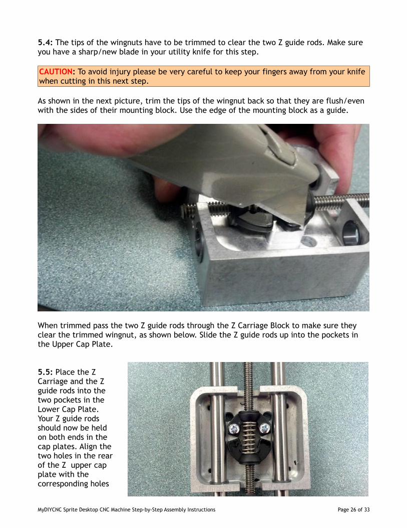
5.4: The tips of the wingnuts have to be trimmed to clear the two Z guide rods. Make sureyou have a sharp/new blade in your utility knife for this step.
CAUTION: To avoid injury please be very careful to keep your fingers away from your knifewhen cutting in this next step.
As shown in the next picture, trim the tips of the wingnut back so that they are flush/evenwith the sides of their mounting block. Use the edge of the mounting block as a guide.
When trimmed pass the two Z guide rods through the Z Carriage Block to make sure theyclear the trimmed wingnut, as shown below. Slide the Z guide rods up into the pockets inthe Upper Cap Plate.
5.5: Place the ZCarriage and the Zguide rods into thetwo pockets in theLower Cap Plate.Your Z guide rodsshould now be heldon both ends in thecap plates. Align thetwo holes in the rearof the Z upper capplate with thecorresponding holes
MyDIYCNC Sprite Desktop CNC Machine Step-by-Step Assembly Instructions Page 26 of 33
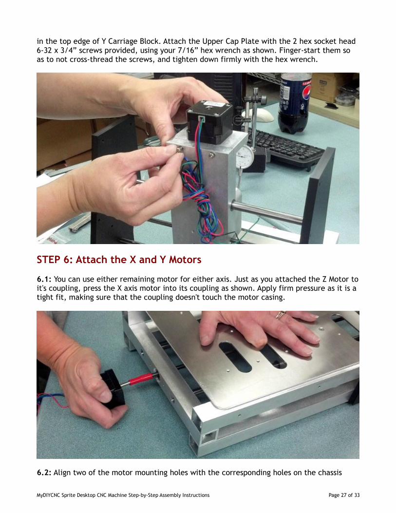
in the top edge of Y Carriage Block. Attach the Upper Cap Plate with the 2 hex socket head6-32 x 3/4” screws provided, using your 7/16” hex wrench as shown. Finger-start them soas to not cross-thread the screws, and tighten down firmly with the hex wrench.
STEP 6: Attach the X and Y Motors
6.1: You can use either remaining motor for either axis. Just as you attached the Z Motor toit's coupling, press the X axis motor into its coupling as shown. Apply firm pressure as it is atight fit, making sure that the coupling doesn't touch the motor casing.
6.2: Align two of the motor mounting holes with the corresponding holes on the chassis
MyDIYCNC Sprite Desktop CNC Machine Step-by-Step Assembly Instructions Page 27 of 33
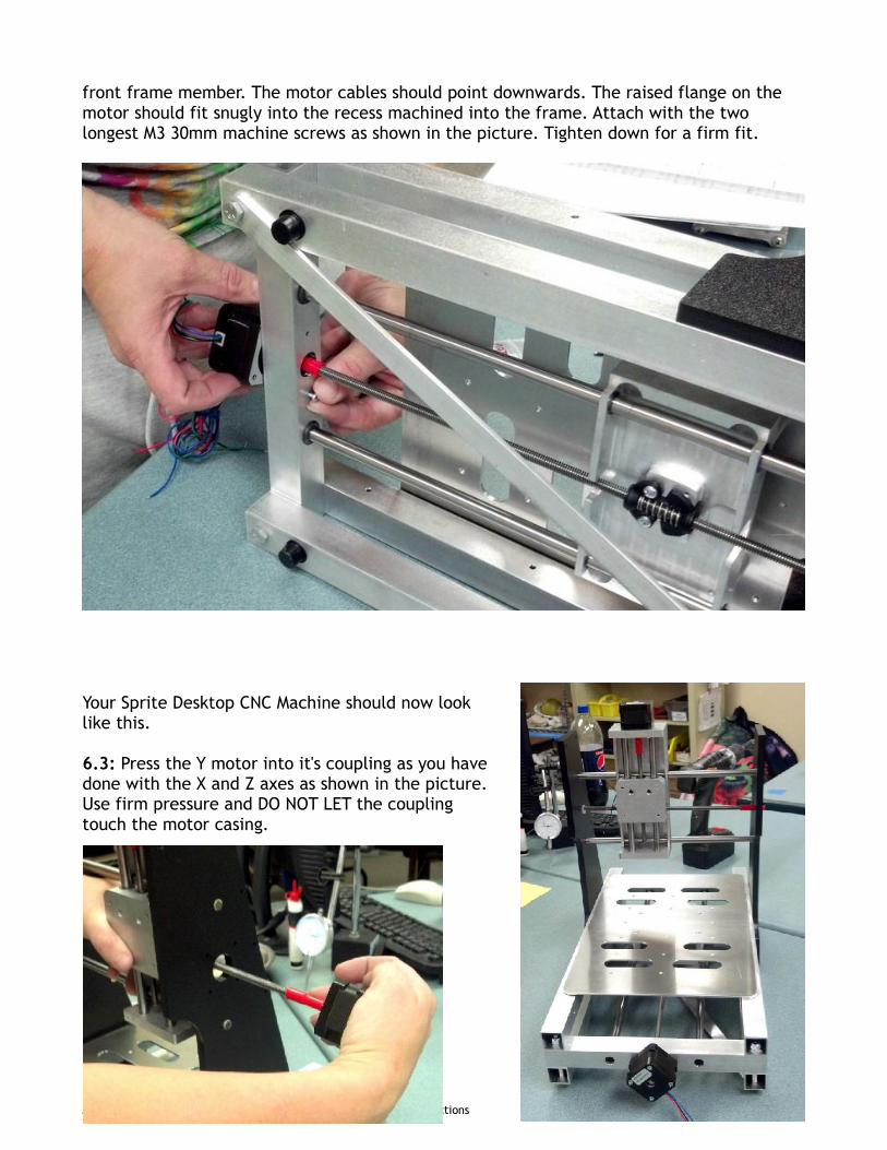
front frame member. The motor cables should point downwards. The raised flange on themotor should fit snugly into the recess machined into the frame. Attach with the twolongest M3 30mm machine screws as shown in the picture. Tighten down for a firm fit.
Your Sprite Desktop CNC Machine should now looklike this.
6.3: Press the Y motor into it's coupling as you havedone with the X and Z axes as shown in the picture.Use firm pressure and DO NOT LET the couplingtouch the motor casing.
MyDIYCNC Sprite Desktop CNC Machine Step-by-Step Assembly Instructions Page 28 of 33
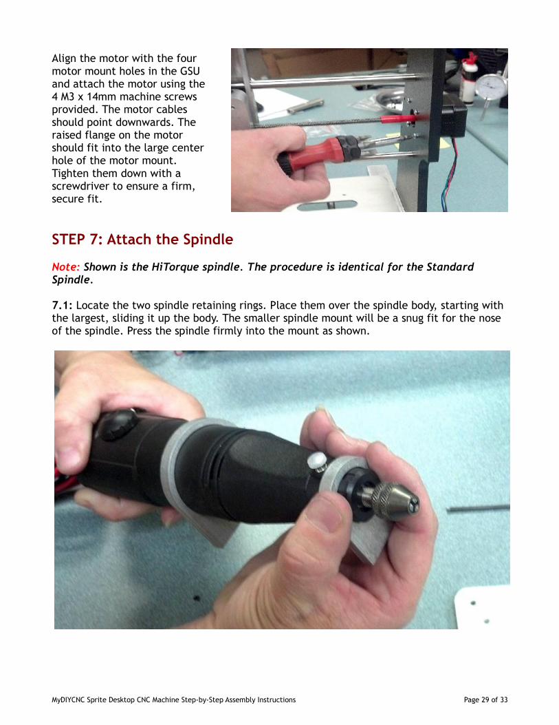
Align the motor with the fourmotor mount holes in the GSUand attach the motor using the4 M3 x 14mm machine screwsprovided. The motor cablesshould point downwards. Theraised flange on the motorshould fit into the large centerhole of the motor mount.Tighten them down with ascrewdriver to ensure a firm,secure fit.
STEP 7: Attach the Spindle
Note: Shown is the HiTorque spindle. The procedure is identical for the StandardSpindle.
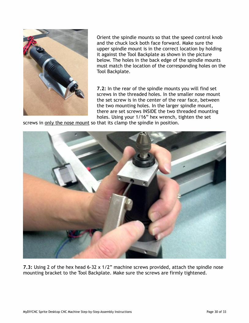
7.1: Locate the two spindle retaining rings. Place them over the spindle body, starting withthe largest, sliding it up the body. The smaller spindle mount will be a snug fit for the noseof the spindle. Press the spindle firmly into the mount as shown.
MyDIYCNC Sprite Desktop CNC Machine Step-by-Step Assembly Instructions Page 29 of 33
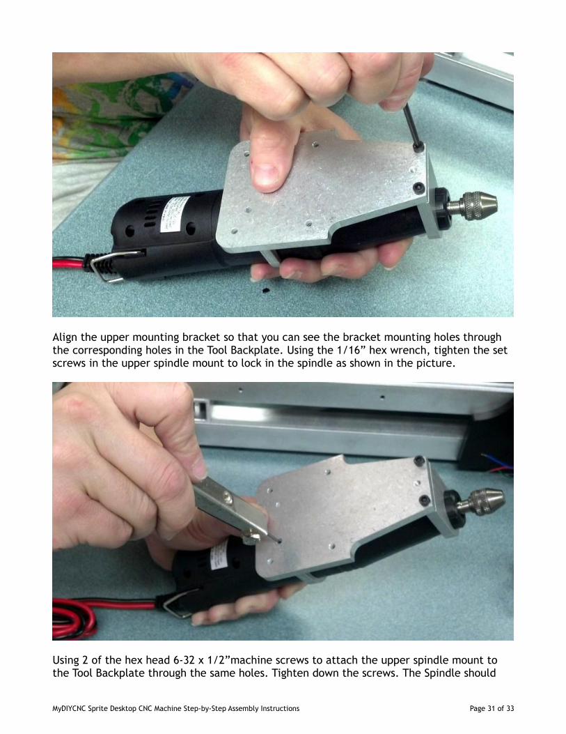
Orient the spindle mounts so that the speed control knoband the chuck lock both face forward. Make sure theupper spindle mount is in the correct location by holdingit against the Tool Backplate as shown in the picturebelow. The holes in the back edge of the spindle mountsmust match the location of the corresponding holes on theTool Backplate.
7.2: In the rear of the spindle mounts you will find setscrews in the threaded holes. In the smaller nose mountthe set screw is in the center of the rear face, betweenthe two mounting holes. In the larger spindle mount,there are set screws INSIDE the two threaded mountingholes. Using your 1/16” hex wrench, tighten the set
screws in only the nose mount so that its clamp the spindle in position.
7.3: Using 2 of the hex head 6-32 x 1/2” machine screws provided, attach the spindle nosemounting bracket to the Tool Backplate. Make sure the screws are firmly tightened.
MyDIYCNC Sprite Desktop CNC Machine Step-by-Step Assembly Instructions Page 30 of 33
Align the upper mounting bracket so that you can see the bracket mounting holes throughthe corresponding holes in the Tool Backplate. Using the 1/16” hex wrench, tighten the setscrews in the upper spindle mount to lock in the spindle as shown in the picture.
Using 2 of the hex head 6-32 x 1/2”machine screws to attach the upper spindle mount tothe Tool Backplate through the same holes. Tighten down the screws. The Spindle should
MyDIYCNC Sprite Desktop CNC Machine Step-by-Step Assembly Instructions Page 31 of 33
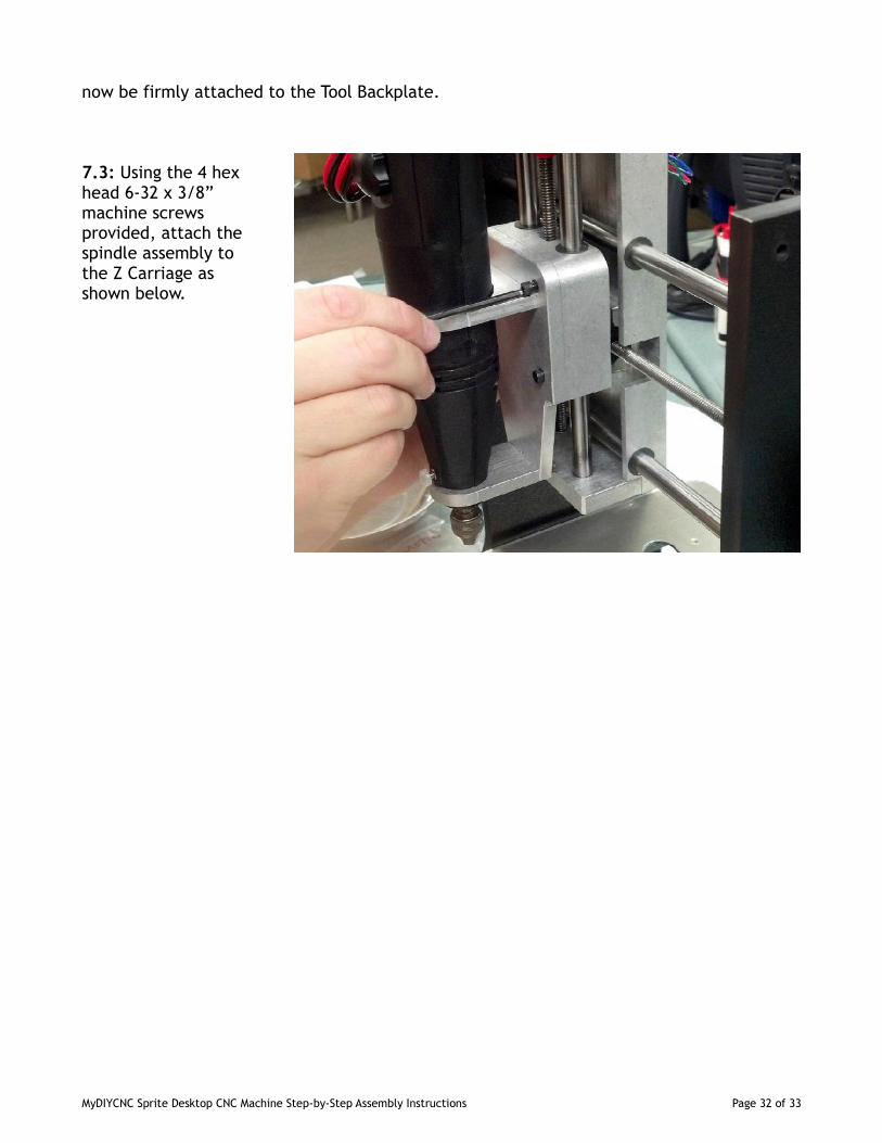
now be firmly attached to the Tool Backplate.
7.3: Using the 4 hexhead 6-32 x 3/8”machine screwsprovided, attach thespindle assembly tothe Z Carriage asshown below.
MyDIYCNC Sprite Desktop CNC Machine Step-by-Step Assembly Instructions Page 32 of 33
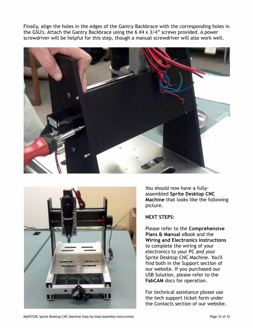
Finally, align the holes in the edges of the Gantry Backbrace with the corresponding holes inthe GSU's. Attach the Gantry Backbrace using the 6 #4 x 3/4” screws provided. A powerscrewdriver will be helpful for this step, though a manual screwdriver will also work well.
You should now have a fully-assembled Sprite Desktop CNCMachine that looks like the followingpicture.
NEXT STEPS:
Please refer to the ComprehensivePlans & Manual eBook and theWiring and Electronics Instructionsto complete the wiring of yourelectronics to your PC and yourSprite Desktop CNC Machine. You'llfind both in the Support section ofour website. If you purchased ourUSB Solution, please refer to theFabCAM docs for operation.
For technical assistance please usethe tech support ticket form underthe Contacts section of our website.
MyDIYCNC Sprite Desktop CNC Machine Step-by-Step Assembly Instructions Page 33 of 33