Embed Size (px)
Citation preview
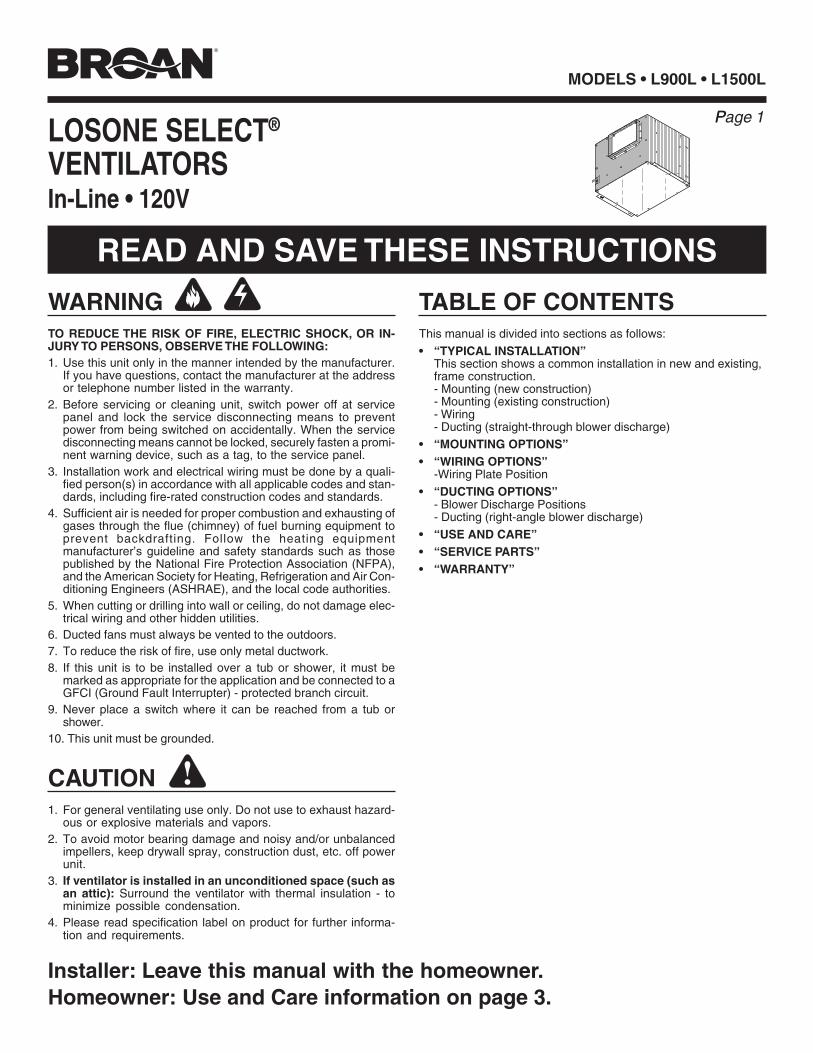
Page 1
MODELS • L900L • L1500L
!
WARNINGTO REDUCE THE RISK OF FIRE, ELECTRIC SHOCK, OR IN-JURY TO PERSONS, OBSERVE THE FOLLOWING:1. Use this unit only in the manner intended by the manufacturer.
If you have questions, contact the manufacturer at the addressor telephone number listed in the warranty.
2. Before servicing or cleaning unit, switch power off at servicepanel and lock the service disconnecting means to preventpower from being switched on accidentally. When the servicedisconnecting means cannot be locked, securely fasten a promi-nent warning device, such as a tag, to the service panel.
3. Installation work and electrical wiring must be done by a quali-fied person(s) in accordance with all applicable codes and stan-dards, including fire-rated construction codes and standards.
4. Sufficient air is needed for proper combustion and exhausting ofgases through the flue (chimney) of fuel burning equipment toprevent backdrafting. Follow the heating equipmentmanufacturer’s guideline and safety standards such as thosepublished by the National Fire Protection Association (NFPA),and the American Society for Heating, Refrigeration and Air Con-ditioning Engineers (ASHRAE), and the local code authorities.
5. When cutting or drilling into wall or ceiling, do not damage elec-trical wiring and other hidden utilities.
6. Ducted fans must always be vented to the outdoors.7. To reduce the risk of fire, use only metal ductwork.8. If this unit is to be installed over a tub or shower, it must be
marked as appropriate for the application and be connected to aGFCI (Ground Fault Interrupter) - protected branch circuit.
9. Never place a switch where it can be reached from a tub orshower.
10. This unit must be grounded.
CAUTION1. For general ventilating use only. Do not use to exhaust hazard-
ous or explosive materials and vapors.2. To avoid motor bearing damage and noisy and/or unbalanced
impellers, keep drywall spray, construction dust, etc. off powerunit.
3. If ventilator is installed in an unconditioned space (such asan attic): Surround the ventilator with thermal insulation - tominimize possible condensation.
4. Please read specification label on product for further informa-tion and requirements.
LOSONE SELECT®
VENTILATORSIn-Line • 120V
READ AND SAVE THESE INSTRUCTIONS
TABLE OF CONTENTSThis manual is divided into sections as follows:
• “TYPICAL INSTALLATION”This section shows a common installation in new and existing,frame construction.- Mounting (new construction)- Mounting (existing construction)- Wiring- Ducting (straight-through blower discharge)
• “MOUNTING OPTIONS”• “WIRING OPTIONS”
-Wiring Plate Position
• “DUCTING OPTIONS”- Blower Discharge Positions- Ducting (right-angle blower discharge)
• “USE AND CARE”• “SERVICE PARTS”• “WARRANTY”
Installer: Leave this manual with the homeowner.Homeowner: Use and Care information on page 3.
Page 1
MODELS • L900L • L1500L
Page 2
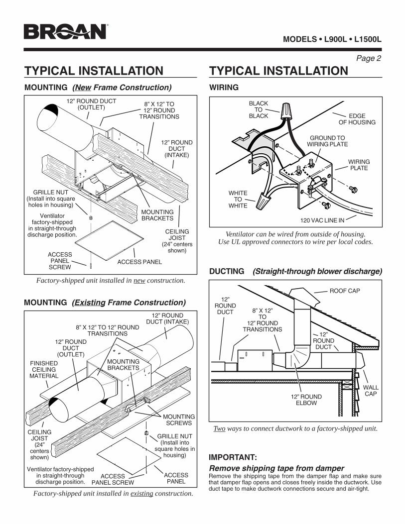
TYPICAL INSTALLATIONMOUNTING (New Frame Construction)
CEILINGJOIST
(24”centersshown)
12” ROUNDDUCT
(OUTLET)
ACCESSPANEL
Factory-shipped unit installed in new construction.
MOUNTINGSCREWS
ACCESSPANEL SCREW
Ventilator factory-shippedin straight-throughdischarge position.
MOUNTINGBRACKETS
MOUNTING (Existing Frame Construction)
Factory-shipped unit installed in existing construction.
TYPICAL INSTALLATIONWIRING
WIRINGPLATE
WHITETO
WHITE
BLACKTO
BLACK EDGEOF HOUSING
120 VAC LINE IN
GROUND TOWIRING PLATE
ACCESSPANEL
SCREWDUCTING (Straight-through blower discharge)
Two ways to connect ductwork to a factory-shipped unit.
Ventilator can be wired from outside of housing.Use UL approved connectors to wire per local codes.
ROOF CAP
12” ROUNDELBOW
12”ROUNDDUCT
WALLCAP
IMPORTANT:Remove shipping tape from damperRemove the shipping tape from the damper flap and make surethat damper flap opens and closes freely inside the ductwork. Useduct tape to make ductwork connections secure and air-tight.
8” X 12”TO
12” ROUNDTRANSITIONS8” X 12” TO 12” ROUND
TRANSITIONS
12” ROUND DUCT(OUTLET)
FINISHEDCEILING
MATERIAL
Ventilatorfactory-shipped
in straight-throughdischarge position.
MOUNTINGBRACKETS
8” X 12” TO12” ROUND
TRANSITIONS
CEILINGJOIST
(24” centersshown)
ACCESS PANEL
12” ROUNDDUCT
(INTAKE)
12” ROUNDDUCT (INTAKE)
12”ROUNDDUCT
GRILLE NUT(Install into squareholes in housing)
GRILLE NUT(Install into
square holes inhousing)
Page 3
MODELS • L900L • L1500L
���������yyyyyyyyy18"
1½"to
2½"
������������������������������������������������������������������������������������������������������������������������������������������������������yyyyyy��������������������������������������������������yy
���������yyyyyyyyy18"
1½"to
2½"
������������������������������������������������������������������������������������������������������������������������������������������������������yyyyyy��������������������������������������������������yy
���yyy ���yyy22"
�y ���yyy22"
11/8"MAX.
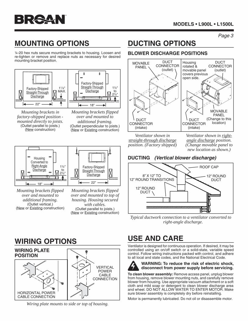
MOUNTING OPTIONS
WIRING OPTIONS
DUCTING OPTIONS
Mounting brackets infactory-shipped position -mounted directly to joists.
(Outlet parallel to joists.)(New construction)
¼-20 hex nuts secure mounting brackets to housing. Loosen andre-tighten or remove and replace nuts as necessary for desiredmounting bracket position.
Mounting brackets flippedover and mounted toadditional framing.
(Outlet perpendicular to joists.)(New or Existing construction)
BLOWER DISCHARGE POSITIONS
WIRING PLATEPOSITION
Wiring plate mounts to side or top of housing.
HORIZONTAL POWERCABLE CONNECTION
VERTICALPOWERCABLE
CONNECTION
Ventilator shown instraight-through dischargeposition. (Factory shipped)
DUCTCONNECTOR
(intake)
Ventilator shown in right-angle discharge position.(Change movable panel tonew location as shown.)
MOVABLEPANEL
DUCTING (Vertical blower discharge)
Typical ductwork connection to a ventilator converted toright-angle discharge.
ROOF CAP
12” ROUNDDUCT
WARNING: To reduce the risk of electric shock,disconnect from power supply before servicing.
To clean blower assembly: Remove access panel, unplug blowerfrom housing, remove blower mounting nuts, and carefully removeblower from housing. Use appropriate vacuum attachment or a softcloth and mild soap or detergent to clean blower discharge areaand wheel. DO NOT ALLOW WATER TO ENTER MOTOR. Makesure blower assembly is completely dry before reinstalling.
Motor is permanently lubricated. Do not oil or disassemble motor.
USE AND CAREVentilator is designed for continuous operation. If desired, it may becontrolled using an on/off switch or a solid-state, variable speedcontrol. Follow wiring instructions packed with control, and adhereto all local and state codes, and the National Electrical Code.
Factory-ShippedStraight-Through
Discharge
Factory-ShippedStraight-Through
Discharge
HousingConverted toRight-AngleDischarge
Mounting brackets flippedover and mounted toadditional framing.
(Outlet vertical.)(New or Existing construction)
Mounting brackets flippedover and mounted to top ofhousing. Housing secured
with cables.(Outlet parallel to joists.)
(New or Existing construction)
Factory-ShippedStraight-Through
Discharge
MOVABLEPANEL
(Change to thislocation)
8” X 12” TO12” ROUND TRANSITIONS
DUCTCONNECTOR
(outlet)
DUCTCONNECTOR
(intake)
DUCTCONNECTOR
(outlet)
Housingrotated &movable panelcovers previousopen side.
12” ROUNDDUCT
MODELS • L900L • L1500L
Page 4
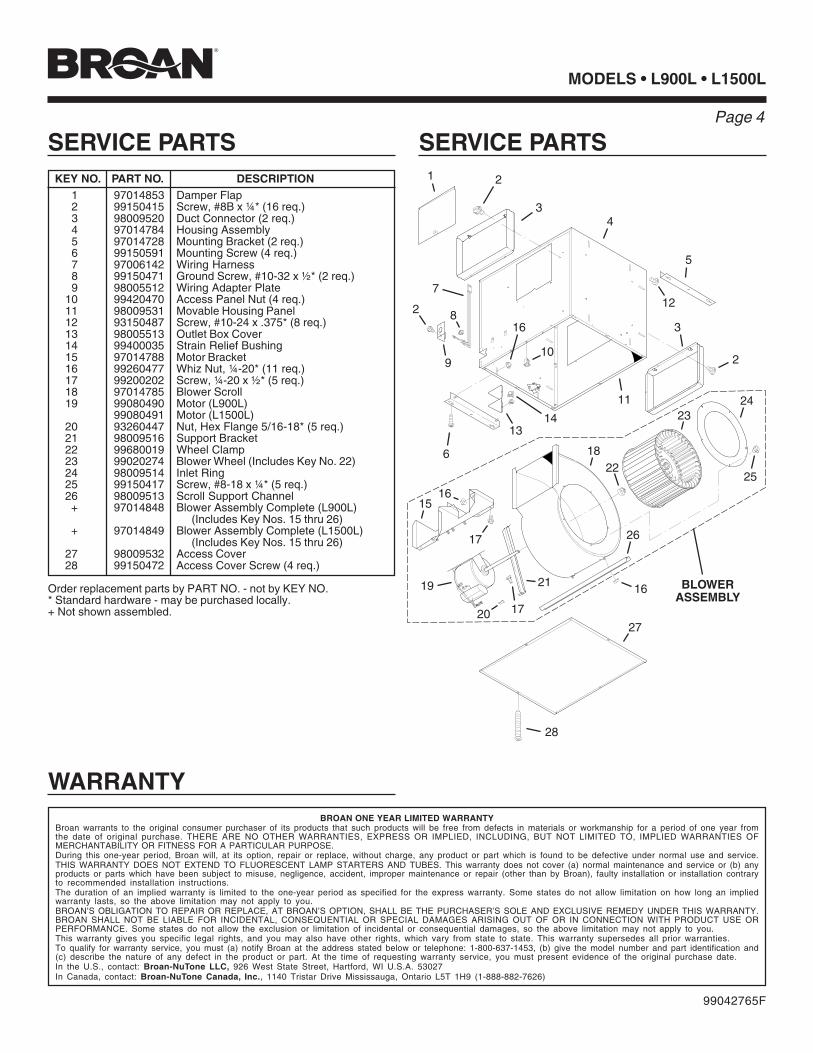
SERVICE PARTS SERVICE PARTSKEY NO. PART NO. DESCRIPTION
1 97014853 Damper Flap2 99150415 Screw, #8B x ¼* (16 req.)3 98009520 Duct Connector (2 req.)4 97014784 Housing Assembly5 97014728 Mounting Bracket (2 req.)6 99150591 Mounting Screw (4 req.)7 97006142 Wiring Harness8 99150471 Ground Screw, #10-32 x ½* (2 req.)9 98005512 Wiring Adapter Plate
10 99420470 Access Panel Nut (4 req.)11 98009531 Movable Housing Panel12 93150487 Screw, #10-24 x .375* (8 req.)13 98005513 Outlet Box Cover14 99400035 Strain Relief Bushing15 97014788 Motor Bracket16 99260477 Whiz Nut, ¼-20* (11 req.)17 99200202 Screw, ¼-20 x ½* (5 req.)18 97014785 Blower Scroll19 99080490 Motor (L900L)
99080491 Motor (L1500L)20 93260447 Nut, Hex Flange 5/16-18* (5 req.)21 98009516 Support Bracket22 99680019 Wheel Clamp23 99020274 Blower Wheel (Includes Key No. 22)24 98009514 Inlet Ring25 99150417 Screw, #8-18 x ¼* (5 req.)26 98009513 Scroll Support Channel+ 97014848 Blower Assembly Complete (L900L)
(Includes Key Nos. 15 thru 26)+ 97014849 Blower Assembly Complete (L1500L)
(Includes Key Nos. 15 thru 26)27 98009532 Access Cover28 99150472 Access Cover Screw (4 req.)
Order replacement parts by PART NO. - not by KEY NO.* Standard hardware - may be purchased locally.+ Not shown assembled.
1 2
3
5
6
7
2 8
9
12
10
14
1516
17
18
21
16
4
22
13
19
23
20
24
17
26
27
28
3
11
16
25
2
BLOWERASSEMBLY
99042765F
WARRANTYBROAN ONE YEAR LIMITED WARRANTY
Broan warrants to the original consumer purchaser of its products that such products will be free from defects in materials or workmanship for a period of one year fromthe date of original purchase. THERE ARE NO OTHER WARRANTIES, EXPRESS OR IMPLIED, INCLUDING, BUT NOT LIMITED TO, IMPLIED WARRANTIES OFMERCHANTABILITY OR FITNESS FOR A PARTICULAR PURPOSE.During this one-year period, Broan will, at its option, repair or replace, without charge, any product or part which is found to be defective under normal use and service.THIS WARRANTY DOES NOT EXTEND TO FLUORESCENT LAMP STARTERS AND TUBES. This warranty does not cover (a) normal maintenance and service or (b) anyproducts or parts which have been subject to misuse, negligence, accident, improper maintenance or repair (other than by Broan), faulty installation or installation contraryto recommended installation instructions.The duration of an implied warranty is limited to the one-year period as specified for the express warranty. Some states do not allow limitation on how long an impliedwarranty lasts, so the above limitation may not apply to you.BROAN’S OBLIGATION TO REPAIR OR REPLACE, AT BROAN’S OPTION, SHALL BE THE PURCHASER’S SOLE AND EXCLUSIVE REMEDY UNDER THIS WARRANTY.BROAN SHALL NOT BE LIABLE FOR INCIDENTAL, CONSEQUENTIAL OR SPECIAL DAMAGES ARISING OUT OF OR IN CONNECTION WITH PRODUCT USE ORPERFORMANCE. Some states do not allow the exclusion or limitation of incidental or consequential damages, so the above limitation may not apply to you.This warranty gives you specific legal rights, and you may also have other rights, which vary from state to state. This warranty supersedes all prior warranties.To qualify for warranty service, you must (a) notify Broan at the address stated below or telephone: 1-800-637-1453, (b) give the model number and part identification and(c) describe the nature of any defect in the product or part. At the time of requesting warranty service, you must present evidence of the original purchase date.In the U.S., contact: Broan-NuTone LLC, 926 West State Street, Hartford, WI U.S.A. 53027In Canada, contact: Broan-NuTone Canada, Inc., 1140 Tristar Drive Mississauga, Ontario L5T 1H9 (1-888-882-7626)
Page 5
MODELS • L900L • L1500LMODELOS
!
ADVERTENCIAPARA REDUCIR EL RIESGO DE INCENDIO, GOLPE ELÉCTRICO,O LESIÓN A PERSONAS, OBSERVE LO SIGUIENTE:1. Use esta unidad solamente de la manera indicada por el fabricante. Si
tiene preguntas, póngase en contacto con el fabricante a la dirección oteléfono que aparecen en la garantía.
2. Antes de limpiar o de poner en servicio la unidad, apague el interruptoren el panel de servicio, y asegure el panel de servicio para evitar quese encienda accidentalmente. Cuando el dispositivo para desconectarel servicio eléctrico no puede ser cerrado con algún tipo de traba,sujete fuertemente al panel de servicio, una etiqueta de advertenciaprominente.
3. El trabajo de instalación y cableado eléctrico deben estar hechos porpersonal capacitado de acuerdo con todos los códigos y estándaresaplicables, incluyendo códigos y estándares de construcción a pruebade incendios.
4. Se necesita suficiente aire para la combustión y extracción de gasespor la chimenea del equipo que quema combustible para evitar laretrogresión de las llamas. Siga las directrices del fabricante yestándares de seguridad como los publicados por la AsociaciónNacional de Protección Contra Incendios (o por sus siglas en inglésNFPA), y la Sociedad Americana de Ingenieros de Calefacción,Refrigeración, y Aire Acondicionado (o por sus sigles en inglésASHRAE), y los códigos de las autoridades locales.
5. Cuando corte o taladre en una pared o cielo raso, no dañe cableadoeléctrico o instalaciones no visibles.
6. Ventiladores con conductos siempre deben extraer hacia el exterior.7. Para reducir el riesgo de incendio, use sólo ductos de metal.8. Si esta unidad va a instalarse sobre una bañera o ducha, debe
marcársela como correcta para dicha aplicación y debe conectarsea un protegido GFCI (Cortacicuito Accidental a Tierra).
9. Nunca instale un interruptor donde se pueda alcanzar desde unabañera o ducha.
10. Esta unidad se debe conectar a tierra.
CUIDADO1. Para uso de ventilación general solamente. No lo use para extraer
materiales o vapores peligrosos o explosivos.2. Para evitar daño a los cojinetes del motor y hélices ruidosas y/o
desequilibradas, mantenga la unidad de potencia lejos de rocíos deyeso, polvo de construcción, etc.
3. Si el ventilador se instala en un área sin acondicionamiento (comopor ejemplo en un ático): Rodee el ventilador con material deaislamiento térmico para minimizar la posible condensación.
4. Para más información y requisitos favor leer la etiqueta deespecificaciones del producto.
VENTILADORESLOSONE SELECT®
Instalador: Deje este manual con el dueño de casa.
Dueño de casa: Información del uso y mantenimiento en la página 7.
Para montaje en línea • 120 V
LEA Y CONSERVE ESTAS INSTRUCCIONES
Este manual consiste en las siguientes secciones:• “INSTALACIÓN TÍPICA”Esta sección muestra una instalación común en una estructuranueva y en una existente.- Montaje (estructura nueva)- Montaje (estructura existente)- Conexiones eléctricas- Colocación de conductos (descarga derecho por del ventilador)• “OPCIONES DE MONTAJE”• “OPCIONES PARA LA CONEXIÓN ELÉCTRICA”- Colocación de la placa de conexiones• “OPCIONES PARA LA COLOCACIÓN DE CONDUCTOS”- Posiciones de la descarga del ventilador- Colocación de conductos (descarga ángulo recto del ventilador)• “USO Y CUIDADO”• “PIEZAS DE SERVICIO”• “GARANTÍA”
CONTENDIO
Página
MODELS • L900L • L1500L
Page 6
MODELOS
Página
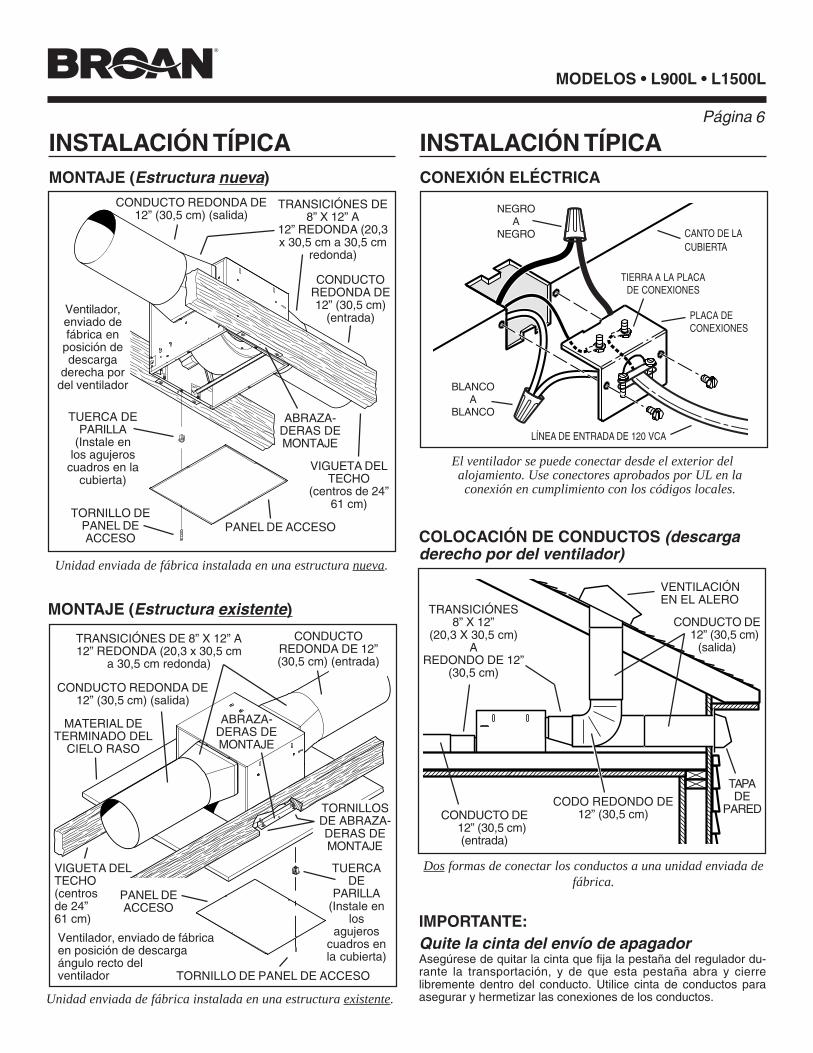
INSTALACIÓN TÍPICAMONTAJE (Estructura nueva)
Unidad enviada de fábrica instalada en una estructura nueva.
MONTAJE (Estructura existente)
Unidad enviada de fábrica instalada en una estructura existente.
INSTALACIÓN TÍPICACONEXIÓN ELÉCTRICA
PLACA DECONEXIONES
BLANCOA
BLANCO
NEGROA
NEGRO CANTO DE LACUBIERTA
TIERRA A LA PLACADE CONEXIONES
COLOCACIÓN DE CONDUCTOS (descargaderecho por del ventilador)
El ventilador se puede conectar desde el exterior delalojamiento. Use conectores aprobados por UL en laconexión en cumplimiento con los códigos locales.
LÍNEA DE ENTRADA DE 120 VCA
IMPORTANTE:Quite la cinta del envío de apagadorAsegúrese de quitar la cinta que fija la pestaña del regulador du-rante la transportación, y de que esta pestaña abra y cierrelibremente dentro del conducto. Utilice cinta de conductos paraasegurar y hermetizar las conexiones de los conductos.
VENTILACIÓNEN EL ALERO
CODO REDONDO DE12” (30,5 cm)
CONDUCTO DE12” (30,5 cm)
(salida)
TAPADE
PARED
TRANSICIÓNES8” X 12”
(20,3 X 30,5 cm)A
REDONDO DE 12”(30,5 cm)
TORNILLO DEPANEL DEACCESO
CONDUCTO REDONDA DE12” (30,5 cm) (salida)
ABRAZA-DERAS DEMONTAJE
VIGUETA DELTECHO
(centros de 24”61 cm)
PANEL DE ACCESO
TRANSICIÓNES DE8” X 12” A
12” REDONDA (20,3x 30,5 cm a 30,5 cm
redonda)
CONDUCTOREDONDA DE12” (30,5 cm)
(entrada)
TORNILLO DE PANEL DE ACCESO
CONDUCTO REDONDA DE12” (30,5 cm) (salida)
ABRAZA-DERAS DEMONTAJE
VIGUETA DELTECHO(centrosde 24”61 cm)
TRANSICIÓNES DE 8” X 12” A12” REDONDA (20,3 x 30,5 cm
a 30,5 cm redonda)
CONDUCTOREDONDA DE 12”(30,5 cm) (entrada)
MATERIAL DETERMINADO DEL
CIELO RASO
Dos formas de conectar los conductos a una unidad enviada defábrica.
CONDUCTO DE12” (30,5 cm)(entrada)
TUERCA DEPARILLA
(Instale enlos agujeros
cuadros en lacubierta)
Ventilador,enviado defábrica en
posición dedescarga
derecha pordel ventilador
TUERCADE
PARILLA(Instale en
losagujeros
cuadros enla cubierta)
PANEL DEACCESO
Ventilador, enviado de fábricaen posición de descargaángulo recto delventilador
TORNILLOSDE ABRAZA-DERAS DEMONTAJE
Page 7
MODELS • L900L • L1500L
���������yyyyyyyyy18"
1½"to
2½"
������������������������������������������������������������������������������������������������������������������������������������������������������yyyyyy��������������������������������������������������yy
���������yyyyyyyyy18"
1½"to
2½"
������������������������������������������������������������������������������������������������������������������������������������������������������yyyyyy��������������������������������������������������yy
���yyy ���yyy22"
�y ���yyy22"
11/8"MAX.
MODELOS
Página
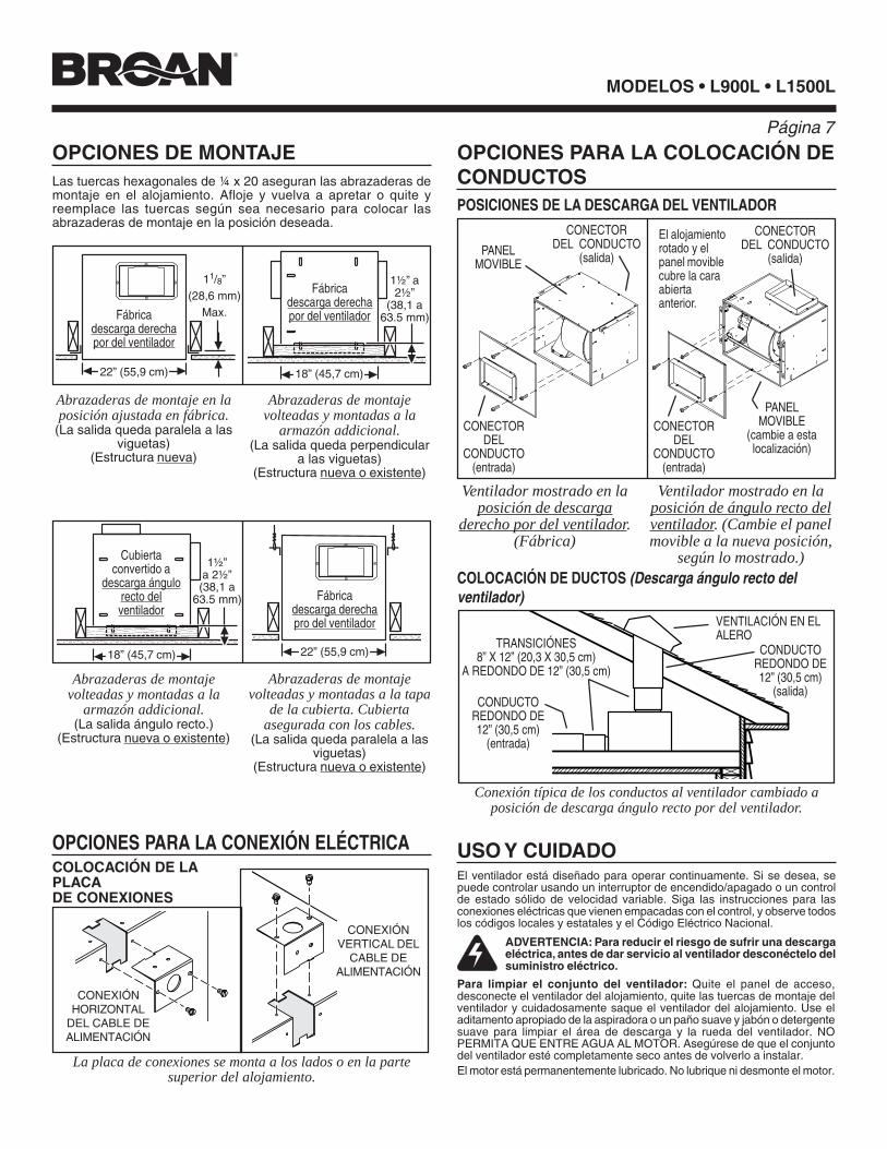
OPCIONES DE MONTAJE
OPCIONES PARA LA CONEXIÓN ELÉCTRICA
OPCIONES PARA LA COLOCACIÓN DECONDUCTOSLas tuercas hexagonales de ¼ x 20 aseguran las abrazaderas de
montaje en el alojamiento. Afloje y vuelva a apretar o quite yreemplace las tuercas según sea necesario para colocar lasabrazaderas de montaje en la posición deseada.
POSICIONES DE LA DESCARGA DEL VENTILADOR
COLOCACIÓN DE LAPLACADE CONEXIONES
La placa de conexiones se monta a los lados o en la partesuperior del alojamiento.
CONEXIÓNHORIZONTAL
DEL CABLE DEALIMENTACIÓN
CONEXIÓNVERTICAL DEL
CABLE DEALIMENTACIÓN
COLOCACIÓN DE DUCTOS (Descarga ángulo recto delventilador)
Conexión típica de los conductos al ventilador cambiado aposición de descarga ángulo recto por del ventilador.
ADVERTENCIA: Para reducir el riesgo de sufrir una descargaeléctrica, antes de dar servicio al ventilador desconéctelo delsuministro eléctrico.
Para limpiar el conjunto del ventilador: Quite el panel de acceso,desconecte el ventilador del alojamiento, quite las tuercas de montaje delventilador y cuidadosamente saque el ventilador del alojamiento. Use eladitamento apropiado de la aspiradora o un paño suave y jabón o detergentesuave para limpiar el área de descarga y la rueda del ventilador. NOPERMITA QUE ENTRE AGUA AL MOTOR. Asegúrese de que el conjuntodel ventilador esté completamente seco antes de volverlo a instalar.El motor está permanentemente lubricado. No lubrique ni desmonte el motor.
USO Y CUIDADOEl ventilador está diseñado para operar continuamente. Si se desea, sepuede controlar usando un interruptor de encendido/apagado o un controlde estado sólido de velocidad variable. Siga las instrucciones para lasconexiones eléctricas que vienen empacadas con el control, y observe todoslos códigos locales y estatales y el Código Eléctrico Nacional.
Abrazaderas de montaje en laposición ajustada en fábrica.
(La salida queda paralela a lasviguetas)
(Estructura nueva)
Abrazaderas de montajevolteadas y montadas a la
armazón addicional.(La salida queda perpendicular
a las viguetas)(Estructura nueva o existente)
Fábricadescarga derechapor del ventilador
Fábricadescarga derechapor del ventilador
Cubiertaconvertido a
descarga ángulorecto delventilador
Abrazaderas de montajevolteadas y montadas a la
armazón addicional.(La salida ángulo recto.)
(Estructura nueva o existente)
Abrazaderas de montajevolteadas y montadas a la tapa
de la cubierta. Cubiertaasegurada con los cables.
(La salida queda paralela a lasviguetas)
(Estructura nueva o existente)
Fábricadescarga derechapro del ventilador
Ventilador mostrado en laposición de descarga
derecho por del ventilador.(Fábrica)
Ventilador mostrado en laposición de ángulo recto delventilador. (Cambie el panelmovible a la nueva posición,
según lo mostrado.)
CONECTORDEL
CONDUCTO(entrada)
22” (55,9 cm)18” (45,7 cm)
22” (55,9 cm) 18” (45,7 cm)
1½”a 2½”
(38,1 a63.5 mm)
1½” a2½”
(38,1 a63.5 mm)
11/8”(28,6 mm)
Max.
PANELMOVIBLE
(cambie a estalocalización)
CONECTORDEL CONDUCTO
(salida)
CONECTORDEL
CONDUCTO(entrada)
CONECTORDEL CONDUCTO
(salida)PANELMOVIBLE
CONDUCTOREDONDO DE12” (30,5 cm)
(salida)
TRANSICIÓNES8” X 12” (20,3 X 30,5 cm)
A REDONDO DE 12” (30,5 cm)
VENTILACIÓN EN ELALERO
CONDUCTOREDONDO DE12” (30,5 cm)
(entrada)
El alojamientorotado y elpanel moviblecubre la caraabiertaanterior.
MODELS • L900L • L1500L
Page 8
MODELOS
Página
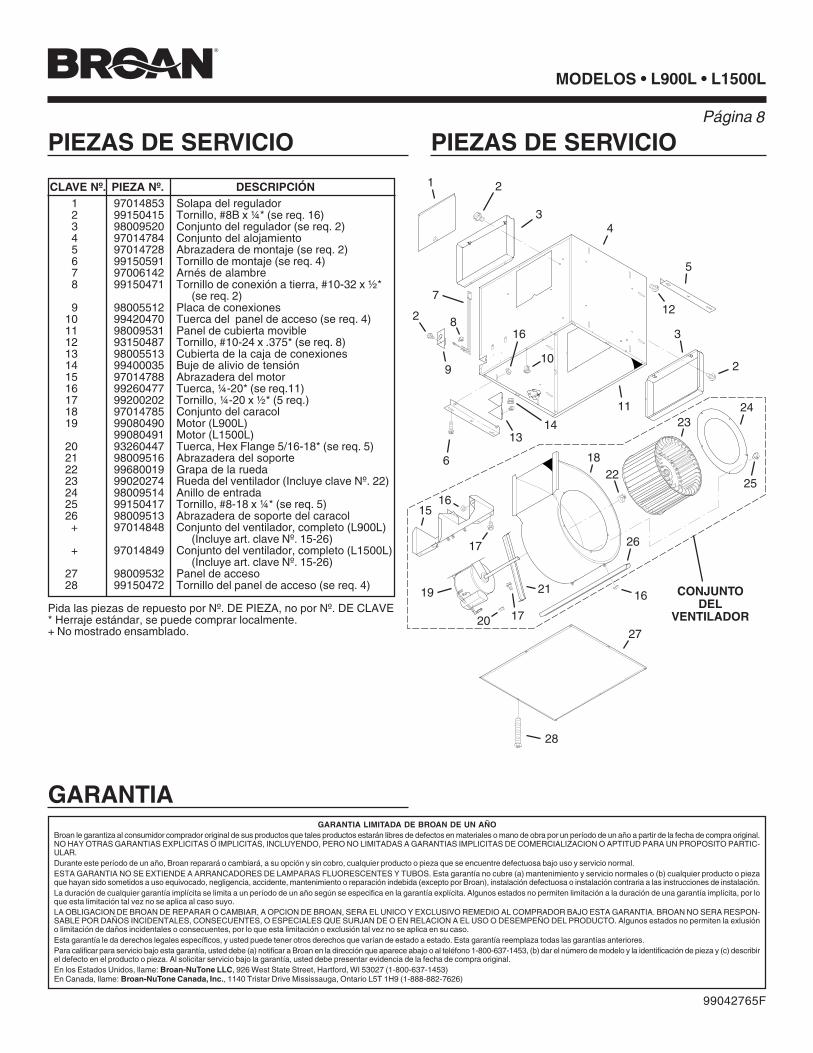
PIEZAS DE SERVICIO PIEZAS DE SERVICIO
CLAVE Nº. PIEZA Nº. DESCRIPCIÓN1 97014853 Solapa del regulador2 99150415 Tornillo, #8B x ¼* (se req. 16)3 98009520 Conjunto del regulador (se req. 2)4 97014784 Conjunto del alojamiento5 97014728 Abrazadera de montaje (se req. 2)6 99150591 Tornillo de montaje (se req. 4)7 97006142 Arnés de alambre8 99150471 Tornillo de conexión a tierra, #10-32 x ½*
(se req. 2)9 98005512 Placa de conexiones
10 99420470 Tuerca del panel de acceso (se req. 4)11 98009531 Panel de cubierta movible12 93150487 Tornillo, #10-24 x .375* (se req. 8)13 98005513 Cubierta de la caja de conexiones14 99400035 Buje de alivio de tensión15 97014788 Abrazadera del motor16 99260477 Tuerca, ¼-20* (se req.11)17 99200202 Tornillo, ¼-20 x ½* (5 req.)18 97014785 Conjunto del caracol19 99080490 Motor (L900L)
99080491 Motor (L1500L)20 93260447 Tuerca, Hex Flange 5/16-18* (se req. 5)21 98009516 Abrazadera del soporte22 99680019 Grapa de la rueda23 99020274 Rueda del ventilador (Incluye clave Nº. 22)24 98009514 Anillo de entrada25 99150417 Tornillo, #8-18 x ¼* (se req. 5)26 98009513 Abrazadera de soporte del caracol+ 97014848 Conjunto del ventilador, completo (L900L)
(Incluye art. clave Nº. 15-26)+ 97014849 Conjunto del ventilador, completo (L1500L)
(Incluye art. clave Nº. 15-26)27 98009532 Panel de acceso28 99150472 Tornillo del panel de acceso (se req. 4)
Pida las piezas de repuesto por Nº. DE PIEZA, no por Nº. DE CLAVE* Herraje estándar, se puede comprar localmente.+ No mostrado ensamblado.
1 2
3
5
6
7
2 8
9
12
10
14
1516
17
18
21
16
4
22
13
19
23
20
24
17
26
27
28
3
11
16
25
2
CONJUNTODEL
VENTILADOR
99042765F
GARANTIAGARANTIA LIMITADA DE BROAN DE UN AÑO
Broan le garantiza al consumidor comprador original de sus productos que tales productos estarán libres de defectos en materiales o mano de obra por un período de un año a partir de la fecha de compra original.NO HAY OTRAS GARANTIAS EXPLICITAS O IMPLICITAS, INCLUYENDO, PERO NO LIMITADAS A GARANTIAS IMPLICITAS DE COMERCIALIZACION O APTITUD PARA UN PROPOSITO PARTIC-ULAR.Durante este período de un año, Broan reparará o cambiará, a su opción y sin cobro, cualquier producto o pieza que se encuentre defectuosa bajo uso y servicio normal.ESTA GARANTIA NO SE EXTIENDE A ARRANCADORES DE LAMPARAS FLUORESCENTES Y TUBOS. Esta garantía no cubre (a) mantenimiento y servicio normales o (b) cualquier producto o piezaque hayan sido sometidos a uso equivocado, negligencia, accidente, mantenimiento o reparación indebida (excepto por Broan), instalación defectuosa o instalación contraria a las instrucciones de instalación.La duración de cualquier garantía implícita se limita a un período de un año según se especifica en la garantía explícita. Algunos estados no permiten limitación a la duración de una garantía implícita, por loque esta limitación tal vez no se aplica al caso suyo.LA OBLIGACION DE BROAN DE REPARAR O CAMBIAR, A OPCION DE BROAN, SERA EL UNICO Y EXCLUSIVO REMEDIO AL COMPRADOR BAJO ESTA GARANTIA. BROAN NO SERA RESPON-SABLE POR DAÑOS INCIDENTALES, CONSECUENTES, O ESPECIALES QUE SURJAN DE O EN RELACION A EL USO O DESEMPEÑO DEL PRODUCTO. Algunos estados no permiten la exlusióno limitación de daños incidentales o consecuentes, por lo que esta limitación o exclusión tal vez no se aplica en su caso.Esta garantía le da derechos legales específicos, y usted puede tener otros derechos que varían de estado a estado. Esta garantía reemplaza todas las garantías anteriores.Para calificar para servicio bajo esta garantía, usted debe (a) notificar a Broan en la dirección que aparece abajo o al teléfono 1-800-637-1453, (b) dar el número de modelo y la identificación de pieza y (c) describirel defecto en el producto o pieza. Al solicitar servicio bajo la garantía, usted debe presentar evidencia de la fecha de compra original.En los Estados Unidos, llame: Broan-NuTone LLC, 926 West State Street, Hartford, WI 53027 (1-800-637-1453)En Canada, llame: Broan-NuTone Canada, Inc., 1140 Tristar Drive Mississauga, Ontario L5T 1H9 (1-888-882-7626)
Page 9
MODELS • L900L • L1500LMODÈLES
!
AVERTISSEMENTPOUR RÉDUIRE LE RISQUE D´INCENDIE, DE CHOC ÉLECTRIQUEOU DE BLESSURES PERSONNELLES, OBSERVEZ CE QUI SUIT:1. Utilisez cette unité seulement de la façon prévue par le fabricant. Pour
d´autres renseignements, contactez le fabricant à l´adresse ou aunuméro de téléphone qui se trouve dans la garantie.
2. Avant d'effectuer une réparation ou un entretien sur cet appareil, coupezle courant au tableau d'alimentation et verrouillez celui-ci pour empêcherque la tension soit remise accidentellement. Lorsque le verrouillage dela déconnexion n'est pas possible, mettez bien en vue un signald'avertissement telle qu'une étiquette, sur le panneau d'alimentation.
3. L´installation et la pose des fils électriques doivent être effectuées parune ou des personnes qualifiées conformément à tous les codes etnormes applicables, incluant les normes de construction en rapport auxincendies.
4. Il faut suffisamment d´air pour une combustion appropriée etl´échappement des gaz par le tuyau de la cheminée de l´équipementbrûlant du combustible pour prévenir un contre-courant. Suivez lesinstructions du fabricant de l´équipement de chauffage et les normesde sécurité telles que celles publiées par la National Fire ProtectionAssociation (NFPA) et l´American Society for Heating, Refrigerationand Air Conditioning Engineers (ASHRAE) et des autorités du codelocal.
5. Lors de la coupe ou du perçage dans un mur ou un plafond, prenezsoin de ne pas endommager les fils électriques et les autres utilitésdissimulées.
6. La décharge des ventilateurs à conduit par l´évent doit toujours sefaire à l´extérieur.
7. Pour réduire le rsque d’incendie, utilisez seulement des donduits deventilation en métal.
8. Si cette unité doit être installée au-dessus d’une baignoire ou d’unedouche, elle doit être marquée comme étant appropriée pourl’application et être connectée à un circuit dérivé protége GFCI(interrupteur de circuit en cas de défaut de mise à la terre du neutre).
9. Ne placez jamais un interrupteur dans un endroit où il peut êtrerejoint d’une baignoire ou d’une douche.
10. Cette unité doit être mise à la terre.
ATTENTION1. Pour ventilation générale seulement. Ne l´utilisez pas pour évacuer les
vapeurs ou matériaux dangereux ou que peuvent exploser.2. Pour éviter d´endommager les coussinets du moteur et des turbines
bruyantes et/ou mal équilibrées, assurez que l´unité motrice est exemptede poussière provenant des murs en pierres sèches et la construc-tion.
3. Si le ventilateur est installé dans un endroit non conditionné (telqu’un grenier): Entourez le ventilateur d’un isolant thermique afin deréduire toute condensation éventuelle.
4. Veuillez lire l´étiquette de spécifications sur le produit pour d´autresrenseignements et exigences.
VENTILATEURSLOSONE SELECT®
Montage dans ligne • 120 V
LIRE ET CONSERVER CES INSTRUCTIONS
TABLE DES MATIÈRESCe manuel se divise comme suit :
• INSTALLATION TYPIQUECette section montre une installation standard dans un bâtimenten cours de construction ou déjà construit.- Montage (construction en cours)- Montage (construction terminée)- Câblage- Installation des conduits (décharge de soufflerie dans ligne)
• OPTIONS DE MONTAGE• OPTIONS DE CÂBLAGE- Position de la plaque de câblage
• OPTIONS D’INSTALLATION DES CONDUITS- Positions de la décharge de la soufflerie- Installation des conduits (décharge de soufflerie droit angle)
• UTILISATION ET ENTRETIEN• PIÈCES DE RECHANGE• GARANTIE
Installateur: Remetez ce manuel au protpriétaire de maison.Propriétaire de maison: Mode d’utilisation et soin à la page 11.
Page
MODELS • L900L • L1500L
Page 10
MODÈLES
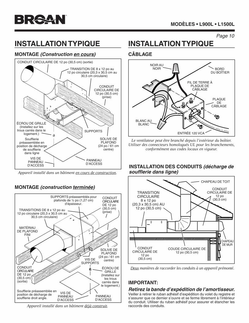
INSTALLATION TYPIQUEMONTAGE (Construction en cours)
Appareil installé dans un bâtiment en cours de construction.
MONTAGE (construction terminée)
Appareil installé dans un bâtiment déjà construit.
INSTALLATION TYPIQUECÂBLAGE
PLAQUEDE
CÂBLAGE
NOIR AUNOIR
BLANC AUBLANC
BORD DU BOÎTIER
ENTRÉE 120 VCA
FIL DE TERRE ÀPLAQUE DECÂBLAGE
INSTALLATION DES CONDUITS (décharge desoufflerie dans ligne)
Deux manières de raccorder les conduits à un appareil prémonté.
Le ventilateur peut être branché depuis l’extérieur du boîtier.Utiliser des connecteurs homologués UL pour les branchements,
conformément aux codes locaux en vigueur.
IMPORTANT:Retirez la bande d’expédition de l’amortisseur.Veiller à retirer le ruban adhésif d’expédition du volet du registre ets’assurer que ce dernier s’ouvre et se ferme librement à l’intérieurdu conduit. Utiliser du ruban adhésif pour assurer et étancher lesraccords des conduits.
TRANSITIONCIRCULAIRE
8 x 12 po(20,3 x 30,5 cm) AU
12 po (30,5 cm)
CHAPEAU DE TOIT
COUDE CIRCULAIRE DE12 po (30,5 cm)
CHAPEAUDE MUR
CONDUITCIRCULAIRE DE
12 po(30,5 cm)
TRANSITION DE 8 x 12 po au12 po circulaire (20,3 x 30,5 cm au
30,5 cm circulaire)
VIS DEPANNEAUD’ACCESS
SOLIVE DEPLAFOND
(24 po / 61 cmcentre)
CONDUIT CIRCULAIRE DE 12 po (30,5 cm) (sortie)
PANNEAUD’ACCESS
Souffleriepréassemblée en
position de déchargede souffleriedans ligne
SUPPORTS
PANNEAUD’ACCESS
MATÉRIAUDE PLAFOND
FINI
SUPPORTS préassemblés pourplafonds de ½ po (1,27 cm)
d’épaisseur.
Soufflerie préassemblée enposition de décharge desoufflerie droit angle.
CONDUITCIRCULAIREDE 12 po(30,5 cm)(sortie)
TRANSITIONS DE 8 x 12 po au12 po circulaire (20,3 x 30,5 cm au
30,5 cm circulaire)
CONDUITCIRCULAIRE DE12 po (30,5 cm)
(prise)
VIS DEPANNEAUD’ACCESS
CONDUITCIRCULAIREDE 12 po(30,5 cm)(prise)
CONDUITCIRCULAIRE DE
12 po(30,5 cm)
ÉCROU DE GRILLE(Installez sur les
trous carrés dans lelogement.)
ÉCROU DEGRILLE
(Installez surles trous
carrés dansle logement.)
SOLIVE DEPLAFOND
(24 po / 61 cmcentre)VIS DE
SUPPORTS
Page 11
MODELS • L900L • L1500L
���yyy ���yyy22"
���������yyyyyyyyy18"
1½"to
2½"
������������������������������������������������������������������������������������������������������������������������������������������������������yyyyyy��������������������������������������������������yy
�y ���yyy22"
11/8"MAX.
MODÈLES
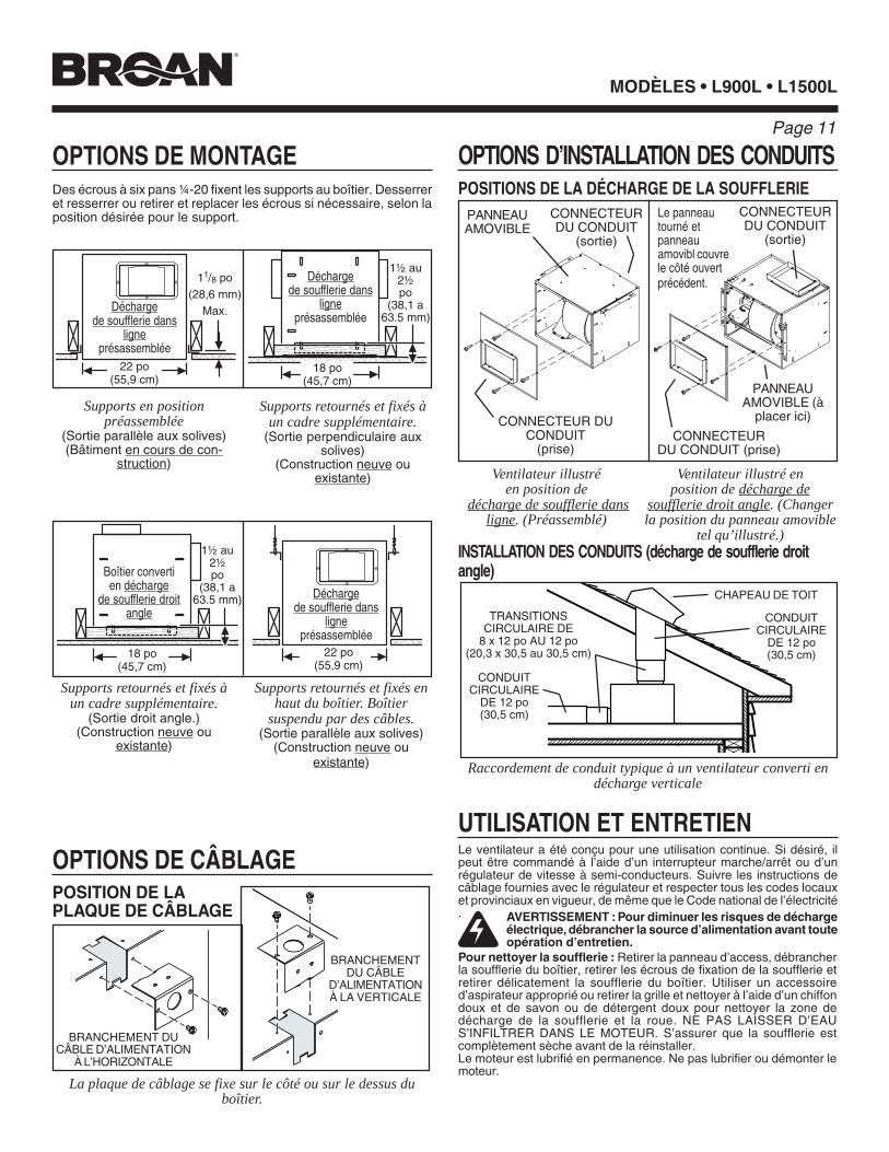
OPTIONS DE MONTAGE
OPTIONS DE CÂBLAGE
OPTIONS D’INSTALLATION DES CONDUITSDes écrous à six pans ¼-20 fixent les supports au boîtier. Desserreret resserrer ou retirer et replacer les écrous si nécessaire, selon laposition désirée pour le support.
POSITIONS DE LA DÉCHARGE DE LA SOUFFLERIE
POSITION DE LAPLAQUE DE CÂBLAGE
La plaque de câblage se fixe sur le côté ou sur le dessus duboîtier.
BRANCHEMENT DUCÂBLE D’ALIMENTATION
À L’HORIZONTALE
BRANCHEMENTDU CÂBLE
D’ALIMENTATIONÀ LA VERTICALE
INSTALLATION DES CONDUITS (décharge de soufflerie droitangle)
Raccordement de conduit typique à un ventilateur converti endécharge verticale
AVERTISSEMENT : Pour diminuer les risques de déchargeélectrique, débrancher la source d’alimentation avant touteopération d’entretien.
Pour nettoyer la soufflerie : Retirer la panneau d’access, débrancherla soufflerie du boîtier, retirer les écrous de fixation de la soufflerie etretirer délicatement la soufflerie du boîtier. Utiliser un accessoired’aspirateur approprié ou retirer la grille et nettoyer à l’aide d’un chiffondoux et de savon ou de détergent doux pour nettoyer la zone dedécharge de la soufflerie et la roue. NE PAS LAISSER D’EAUS’INFILTRER DANS LE MOTEUR. S’assurer que la soufflerie estcomplètement sèche avant de la réinstaller.Le moteur est lubrifié en permanence. Ne pas lubrifier ou démonter lemoteur.
UTILISATION ET ENTRETIENLe ventilateur a été conçu pour une utilisation continue. Si désiré, ilpeut être commandé à l’aide d’un interrupteur marche/arrêt ou d’unrégulateur de vitesse à semi-conducteurs. Suivre les instructions decâblage fournies avec le régulateur et respecter tous les codes locauxet provinciaux en vigueur, de même que le Code national de l’électricité.
Supports en positionpréassemblée
(Sortie parallèle aux solives)(Bâtiment en cours de con-
struction)
22 po(55,9 cm)
Déchargede soufflerie dans
ligneprésassemblée
Supports retournés et fixés àun cadre supplémentaire.
(Sortie perpendiculaire auxsolives)
(Construction neuve ouexistante) Ventilateur illustré
en position de décharge de soufflerie dans
ligne. (Préassemblé)
Ventilateur illustré enposition de décharge de
soufflerie droit angle. (Changerla position du panneau amovible
tel qu’illustré.)
Supports retournés et fixés àun cadre supplémentaire.
(Sortie droit angle.)(Construction neuve ou
existante)
Supports retournés et fixés enhaut du boîtier. Boîtier
suspendu par des câbles.(Sortie parallèle aux solives)
(Construction neuve ouexistante)
TRANSITIONSCIRCULAIRE DE
8 x 12 po AU 12 po(20,3 x 30,5 au 30,5 cm)
CHAPEAU DE TOIT
CONDUITCIRCULAIRE
DE 12 po(30,5 cm)���������yyyyyyyyy18"
1½"to
2½"
������������������������������������������������������������������������������������������������������������������������������������������������������yyyyyy��������������������������������������������������yy
1½ au2½po
(38,1 a63.5 mm)
11/8 po(28,6 mm)
Max.
22 po(55,9 cm)
18 po(45,7 cm)
Déchargede soufflerie dans
ligneprésassemblée
Déchargede soufflerie dans
ligneprésassemblée
18 po(45,7 cm)
Boîtier convertien décharge
de soufflerie droitangle
PANNEAUAMOVIBLE
CONNECTEUR DUCONDUIT
(prise)
PANNEAUAMOVIBLE (à
placer ici)
CONNECTEURDU CONDUIT (prise)
CONNECTEURDU CONDUIT
(sortie)
CONNECTEURDU CONDUIT
(sortie)
CONDUITCIRCULAIRE
DE 12 po(30,5 cm)
1½ au2½po
(38,1 a63.5 mm)
Le panneautourné etpanneauamovibl couvrele côté ouvertprécédent.
MODELS • L900L • L1500L
Page 12
MODÈLES
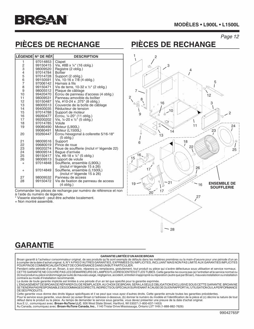
PIÈCES DE RECHANGE PIÈCES DE RECHANGE
99042765F
LÉGENDE NO DE RÉF. DESCRIPTION1 97014853 Clapet2 99150415 Vis, #8B x ¼* (16 oblig.)3 98009520 Registre (2 oblig.)4 97014784 Boîtier5 97014728 Support (2 oblig.)6 99150591 Vis, 10-16 x 7/8 (4 oblig.)7 97006142 Harnais à fils8 99150471 Vis de terre, 10-32 x ½* (2 oblig.)9 98005512 Plaque de câblage
10 99420470 Écrou de panneau d’access (4 oblig.)11 98009531 Panneau amovible du boîtier12 93150487 Vis, #10-24 x .375* (8 oblig.)13 98005513 Couvercle de la boîte de câblage14 99400035 Réducteur de tension15 97014788 Support de moteur16 99260477 Écrou, ¼-20* (11 oblig.)17 99200202 Vis, ¼-20 x ½* (5 oblig.)18 97014785 Volute19 99080490 Moteur (L900L)
99080491 Moteur (L1500L)20 93260447 Écrou hexagonal à collerette 5/16-18*
(5 oblig.)21 98009516 Support22 99680019 Pince de roue23 99020274 Roue de soufflerie (inclut no légende 22)24 98009514 Bague d’arrivée25 99150417 Vis, #8-18 x ¼* (5 oblig.)26 98009513 Support de volute+ 97014848 Soufflerie, ensemble (L900L)
(inclut no légende 15 à 26)+ 97014849 Soufflerie, ensemble (L1500L)
(inclut no légende 15 à 26)27 98009532 Panneau de access28 99150472 Vis de fixation de panneau de access
(4 oblig.)
Commander les pièces de rechange par numéro de référence et nonà l’aide du numéro de légende.* Visserie standard - peut être achetée localement.+ Non montré assemblé.
1 2
3
5
6
7
2 8
9
12
10
14
1516
17
18
21
16
4
22
13
19
23
20
24
17
26
27
28
3
11
16
25
2
ENSEMBLE DESOUFFLERIE
GARANTIE LIMITÉE D’UN AN DE BROANBroan garantit à l’acheteur consommateur original, de ses produits qu’ils sont exempts de défauts dans les matières premières ou la main-d’oeuvre pour une période d’un anà compter de la date d’achat original. IL N’Y A PAS D’AUTRES GARANTIES, EXPRIMÉES OU IMPLICITES, INCLUANT MAIS NON PAS LIMITÉ AUX GARANTIES IMPLICITESPOUR FIN DE COMMERCIALISATION ET DE CONVENANCE DANS UN BUT PARTICULIER.Pendant cette période d’un an, Broan, à son choix, réparera ou remplacera, gratuitement, tout produit ou pièce qui s’avère défectueux sous utilisation et service normaux.CETTE GARANTIE NE COUVRE PAS LES DÉMARREURS DE LAMPES FLUORESCENTES ET LES TUBES. Cette garantie ne couvre pas (a) l’entretien et le service normal ou(b) tout produit ou pièce endommagé par suite de mauvais usage, négligence, accident, entretien inapproprié ou réparation (autre que par Broan), mauvais installation ou installationcontraire au mode d’installation recommandé.La durée de toute garantie implicite est limitée à une période d’un an tel que spécifié pour la garantie exprimée.L’ENGAGEMENT DE BROAN DE RÉPARER OU DE REMPLACER, AU CHOIX DE BROAN, SERA LA SEULE OBLIGATION EXCLUSIVE SOUS CETTE GARANTIE. BROAN NESE TIENDRA PAS RESPONSABLE DES DOMMAGES DIRECTS, INDIRECTS OU SPÉCIAUX SURVENANT À CAUSE DE OU EN RAPPORT À L’UTILISATION OU LA PERFORMANCEDE SES PRODUITS.Cette garantie vous donne des droits légaux spécifiques et il se peut que vous ayez d’autres droits. Cette garantie annule toutes les garanties précédentes.Pour le service sous garantie, vous devez (a) aviser Broan á l'adresse ci-dessous, (b) donner le numéro du modèle et l’identification de la pièce et (c) décrire la nature de toutdéfaut dans le produit ou la pièce. Au temps de demander le service sous garantie, vous devez présenter une preuve de la date d’achat original.Aux E.U., comuniquez avec: Broan-NuTone LLC, 926 West State Street, Hartford, WI 53027 (1-800-637-1453)Au Canada, comuniquez avec: Broan-NuTone Canada, Inc., 1140 Tristar Drive Mississauga, Ontario L5T 1H9 (1-888-882-7626)
GARANTIE