Embed Size (px)
Citation preview
DOE/EM-0428
Reactor SurfaceContamination
StabilizationDeactivation and Decommissioning
Focus Area
Prepared forU.S. Department of Energy
Office of Environmental ManagementOffice of Science and Technology
November 1998
Reactor SurfaceContamination
StabilizationOST Reference #1839
Deactivation and DecommissioningFocus Area
Demonstrated atHanford Site
Richland, Washington
Purpose of this document
Innovative Technology Summary Reports are designed to provide potential users with theinformation they need to quickly determine whether a technology would apply to a particularenvironmental management problem. They are also designed for readers who may recommendthat a technology be considered by prospective users.
Each report describes a technology, system, or process that has been developed and testedwith funding from DOE’s Office of Science and Technology (OST). A report presents the fullrange of problems that a technology, system, or process will address and its advantages to theDOE cleanup in terms of system performance, cost, and cleanup effectiveness. Most reportsinclude comparisons to baseline technologies as well as other competing technologies.Information about commercial availability and technology readiness for implementation is alsoincluded. Innovative Technology Summary Reports are intended to provide summaryinformation. References for more detailed information are provided in an appendix.
Efforts have been made to provide key data describing the performance, cost, and regulatoryacceptance of the technology. If this information was not available at the time of publication, theomission is noted.
All published Innovative Technology Summary Reports are available on the OST Web site athttp://ost.em.doe.gov under “Publications.”
Page iii
U.S. Department of Energy
TABLE OF CONTENTS
1
2
3
4
5
6
7
A
B
C
SUMMARY page 1
TECHNOLOGY DESCRIPTION page 5
PERFORMANCE page 8
TECHNOLOGY APPLICABILITY AND page 16ALTERNATIVE TECHNOLOGIES
COST page 17
REGULATORY/POLICY ISSUES page 20
LESSONS LEARNED page 21
APPENDICES
REFERENCES
COST COMPARISON
ACRONYMS AND ABBREVIATIONS
Page 1
U.S. Department of Energy
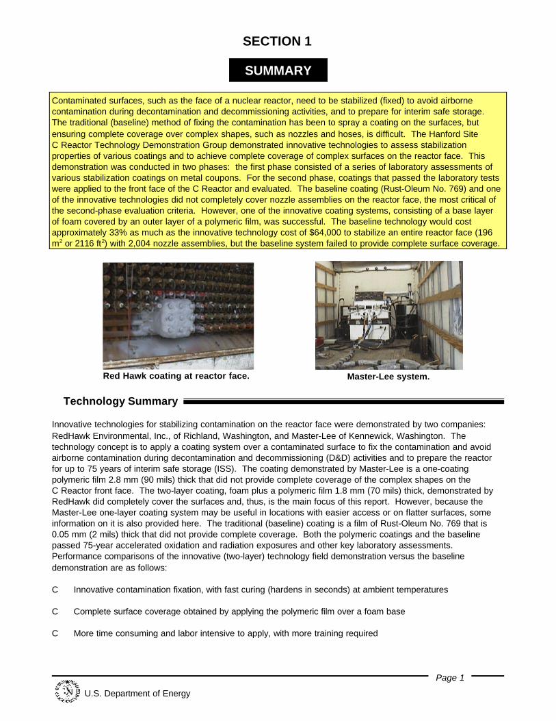
Red Hawk coating at reactor face. Master-Lee system.
SECTION 1
SUMMARY
Contaminated surfaces, such as the face of a nuclear reactor, need to be stabilized (fixed) to avoid airbornecontamination during decontamination and decommissioning activities, and to prepare for interim safe storage. The traditional (baseline) method of fixing the contamination has been to spray a coating on the surfaces, butensuring complete coverage over complex shapes, such as nozzles and hoses, is difficult. The Hanford SiteC Reactor Technology Demonstration Group demonstrated innovative technologies to assess stabilizationproperties of various coatings and to achieve complete coverage of complex surfaces on the reactor face. Thisdemonstration was conducted in two phases: the first phase consisted of a series of laboratory assessments ofvarious stabilization coatings on metal coupons. For the second phase, coatings that passed the laboratory testswere applied to the front face of the C Reactor and evaluated. The baseline coating (Rust-Oleum No. 769) and oneof the innovative technologies did not completely cover nozzle assemblies on the reactor face, the most critical ofthe second-phase evaluation criteria. However, one of the innovative coating systems, consisting of a base layerof foam covered by an outer layer of a polymeric film, was successful. The baseline technology would costapproximately 33% as much as the innovative technology cost of $64,000 to stabilize an entire reactor face (196m2 or 2116 ft2) with 2,004 nozzle assemblies, but the baseline system failed to provide complete surface coverage.
ê Technology Summary
Innovative technologies for stabilizing contamination on the reactor face were demonstrated by two companies: RedHawk Environmental, Inc., of Richland, Washington, and Master-Lee of Kennewick, Washington. Thetechnology concept is to apply a coating system over a contaminated surface to fix the contamination and avoidairborne contamination during decontamination and decommissioning (D&D) activities and to prepare the reactorfor up to 75 years of interim safe storage (ISS). The coating demonstrated by Master-Lee is a one-coatingpolymeric film 2.8 mm (90 mils) thick that did not provide complete coverage of the complex shapes on theC Reactor front face. The two-layer coating, foam plus a polymeric film 1.8 mm (70 mils) thick, demonstrated byRedHawk did completely cover the surfaces and, thus, is the main focus of this report. However, because theMaster-Lee one-layer coating system may be useful in locations with easier access or on flatter surfaces, someinformation on it is also provided here. The traditional (baseline) coating is a film of Rust-Oleum No. 769 that is0.05 mm (2 mils) thick that did not provide complete coverage. Both the polymeric coatings and the baselinepassed 75-year accelerated oxidation and radiation exposures and other key laboratory assessments. Performance comparisons of the innovative (two-layer) technology field demonstration versus the baselinedemonstration are as follows:
C Innovative contamination fixation, with fast curing (hardens in seconds) at ambient temperatures
C Complete surface coverage obtained by applying the polymeric film over a foam base
C More time consuming and labor intensive to apply, with more training required
SUMMARY continued
Page 2
U.S. Department of Energy
C Improved as low as reasonably achievable (ALARA) practice because of the better fixation, but toxicity whilespraying requires additional personal protective equipment (PPE).
Problem Addressed
The U.S. Department of Energy (DOE) is conducting D&D work at many of its nuclear facilities. Typically, thefacilities undergoing D&D are contaminated, either chemically, radiologically, or both. In its D&D work, the DOErequires a coating system that can fix radioactive contamination to surfaces that cannot be cost-effectivelydecontaminated. The ideal coating should have a low toxicity, low air and moisture permeability, excellentadhesive properties, be able to completely cover complex shapes, work over wide temperature ranges, and providehigh resistance to radiation and oxidation over long time periods.
Features and Configuration
The coatings offered by RedHawk and Master-Lee passed the initial laboratory assessments conducted first, andwere subsequently demonstrated. Another foam coating, submitted by Eurotech of La Jolla, California, alsopassed critical laboratory assessments, but the vendor was unable to schedule a demonstration. The features ofthe innovative coating systems evaluated at the C Reactor are:
Two-Layer System: The RedHawk coating system consists of two layers: a polyurethane foam base layercovered by a polyurea film. The same equipment is used for spraying both the foam and the film.
One-Layer System: The Master-Lee coating is a single layer of polyurea film sprayed on the surface.
Potential Markets/Applicability
This technology is potentially valuable for any D&D project where physical removal of radioactive contamination istoo costly or impractical. The DOE, the U.S. Nuclear Regulatory Commission, and the U.S. EnvironmentalProtection Agency all have potential for wide use of this technology at their nuclear facilities. Private-sectorremediation and demolition contractors may find either innovative system suitable, depending on the surfaces tobe treated, for stabilizing contamination.
Advantages of the Innovative Technology
The following table summarizes the advantages and disadvantages of the innovative technology against thebaseline (traditional) coating in key areas. It should be noted that although the baseline coating costs less, is nottoxic, and is faster to apply, it failed to provide complete coverage.
Category Comment
Cost The successful two-layer innovative technology would cost $64,000 to cover an entire reactor face;the baseline would cost $20,900.
Performance The two innovative coatings and the baseline coating passed key laboratory evaluations of agingresistance, but only the two-layer system completely covered complex shapes because a foambase expands to fill areas that are hard to reach.
Secondary Waste All coating systems generate residual organic liquid wastes and contaminated PPE.
ALARA/Safety The RedHawk coating system provided complete coverage and had the highest long-term ALARArating. Exposure is longer during application, and the toxicity of the components is higher thanwith the baseline. Supplied-air respirators are used when applying the innovative coatings.
Ease of Use The baseline coating (Rust-Oleum) was applied in half the time required for the best innovativecoating system, so it can be considered favorable for readily accessible, simple shapes. Theskill level required to apply the baseline is less.
SUMMARY continued
Page 3
U.S. Department of Energy
Operator Concerns
C For the innovative coatings, mobilization and application take longer than for the baseline coating.
C The innovative coating formulations include diisocyanates that are toxic until the components begin to mix atthe spray gun and polymerize.
Skills/Training
Workers must be able to operate paint spray guns and pneumatic equipment. The innovative coatings also requirethat operators have special training and experience with two-component proportioning equipment.
ê Demonstration Summary
The technology demonstration was performed in two phases. For the first phase (August 1997 throughMarch 1998), the coatings were applied by the vendors to small metal coupons and assessed by WyleLaboratories of Huntsville, Alabama. For the second phase of the technology demonstration (March 19 and 24,1998), the baseline and innovative coatings were applied to sections of the C Reactor face nozzle array. Demonstration Site Description
At its former weapons production sites, the DOE is evaluating innovative technologies that might prove valuable forfacility D&D. DOE’s Office of Science & Technology/Deactivation and Decommissioning Focus Area, incollaboration with the Environmental Restoration Program, is undertaking a major effort of demonstrating innovativetechnologies at its sites nationwide. At the Hanford Site, 20 technologies have been demonstrated and assessedagainst baseline technologies currently in use. The Hanford Site Large-Scale Demonstration and DeploymentProject (LSDDP) includes the C Reactor ISS as an important part of the overall effort. If successfullydemonstrated at the Hanford Site, these innovative technologies could be implemented at other DOE sites andsimilar government or commercial facilities.
The innovative technologies described in this report are designed to stabilize radioactive contamination on thecomplex shapes of the C Reactor face. Each face of the C Reactor block, front and rear, is 14 m x 14 m (46 ft x46 ft) and contains a number of nozzle assemblies 0.3 m (1 ft) apart. Each coating system demonstrated wasapplied to sections of the reactor front face.
Regulator Issues
No special regulatory permits are required for the operation and use of the innovative technologies. Thesecoatings can be applied under the requirements of 10 CFR, Parts 20, 835, and proposed 834 for protection ofworkers and the environment from radiological contaminants; and 29 CFR, OSHA worker requirements.
Technology Availability
The innovative coating components for polyurea film are readily available throughout the United States fromselected firms licensed by Huntsman Chemical Corporation of Austin, Texas. RedHawk has modified theformulation and makes it available as “SS-100.” Master-Lee uses a modified formulation available from InstaCote(Erie, Michigan). The polyurethane components are not proprietary and are generally available.
SUMMARY continued
Page 4
U.S. Department of Energy
Technology Limitations/Needs for Future Development
The two-layer foam and film coating system met critical performance objectives. Film coatings, especially thick,durable polymers such as the two innovative formulations demonstrated, either need a base layer over complexshapes or an innovative method of application. Film-only systems would need multi-directional spray tips to coverthe backside of complex shapes. Alternative methods of achieving coverage by one-layer systems might includeattaching a mesh or screen or a rigid cover over the reactor face nozzle assemblies end caps. Then a film couldbe sprayed over the entire mesh or over the rigid cover joints.
ê Contacts
ManagementJohn Duda, FETC, (304) 285-4217Jeff Bruggeman, DOE RL, (509) 376-7121Shannon Saget, DOE RL, (509) 372-4029
Technical InformationStephen Pulsford, BHI, (509) 375-4640Greg Gervais, USACE, (206) 764-6837Jim Anderson, Wyle Laboratories, (256) 837-4411Don Koozer, Master-Lee Engineering, (509) 783-3523Marc Azure, RedHawk Environmental, (509) 946-8608
Licensing InformationDudley Primeaux, Huntsman Chemical Corporation, (512) 483-0148
OthersAll published Innovative Technology Summary Reports are available at http://em-50.em.doe.gov. The TechnologyManagement System, also available through the EM50 Web site, provides information about OST programs,technologies, and problems. The OST Reference Number for Reactor Surface Contaminant Long-TermStabilization is 1839.
Page 5
U.S. Department of Energy
SECTION 2
TECHNOLOGYDESCRIPTION
ê Overall Process/Technology Definition
Coatings offered by RedHawk and Master-Lee were among those that passed laboratory assessments, and thesetwo firms were able to schedule field demonstrations. Both vendors use two-component formulations, whether forfilm or foam, that require an electrically heated proportioning and pumping system. RedHawk, however, uses atwo-layer (foam and film) system, while Master-Lee has a one-layer (film only) coating system. The specificationsare described below.
Material Specifications
Production of polyurea formulations is done by various firms under license from Huntsman Chemical Corporation(Austin, Texas).
The Master-Lee coating material is polyurea film, composed of a pre-polymerized resin and a “hardener” ofdiisocyanate that promotes the formation of InstaCote™ (Erie, Michigan). The polymer formulation is similar topolyurethane, but has added amino groups. The setting time to harden is 5 to 30 seconds. The coating will curein 24 to 48 hours. The temperature of the area to be coated should be a minimum of 12.8°C (55°F). In order toensure good adhesion without aggressive surface preparation, before spraying the polymer formulation a primercoat of a modified acrylic latex is applied with a hand-powered sprayer. (Master-Lee can apply InstaCote over alayer of foam, if desired.)
The RedHawk film material is similar to that used by Master-Lee, except that the material is called PolyShield™,formulated by Specialty Products (Tacoma, Washington). The base layer of polyurethane is allowed to set for5 minutes before the final layer is applied. The final layer, a polyurea film, is sprayed beyond the edges of thefoam for direct adherence to the reactor face. The polyurea is based on amine-terminated polyester resins, aminechain extenders and diisocyanate. It has a service temperature of -51°C to 177°C (-60°F to 350°F) and ishydrophobic. A primer coat of a polyether glycol is required only where the film extends beyond the foam.
Equipment and Power Requirements
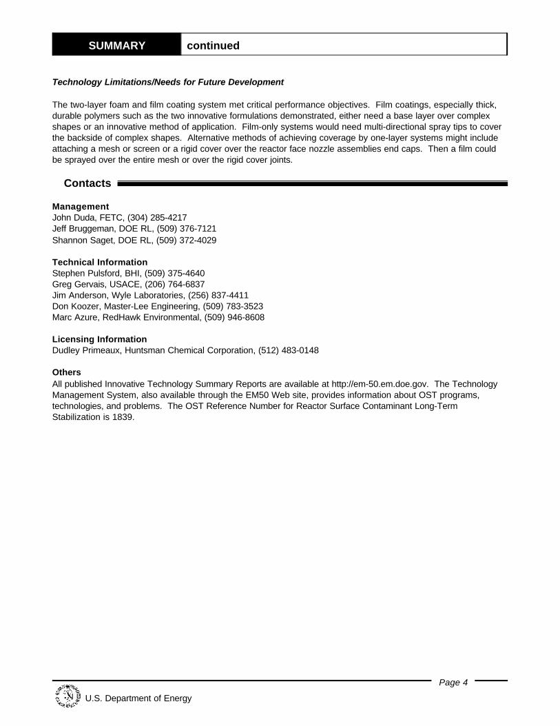
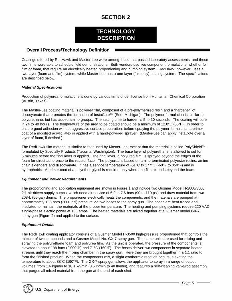
The proportioning and application equipment are shown in Figure 1 and include two Gusmer Model H-2000/35002:1 air-driven supply pumps, which need air service of 6.2 to 7.6 bars (90 to 110 psi) and draw material from two208-L (55-gal) drums. The proportioner electrically heats the components, and the materials are pumped atapproximately 138 bars (2000 psi) pressure via two hoses to the spray gun. The hoses are heat-traced andinsulated to maintain the materials at the proper temperature. The heating and pumping systems require 220 VACsingle-phase electric power at 100 amps. The heated materials are mixed together at a Gusmer model GX-7spray gun (Figure 2) and applied to the surface.
Equipment Details
The RedHawk coating applicator consists of a Gusmer Model H-3500 high-pressure proportioned that controls themixture of two compounds and a Gusmer Model No. GX-7 spray gun. The same units are used for mixing andspraying the polyurethane foam and polyurea film. As the unit is operated, the pressure of the components iselevated to about 138 bars (2,000 lb) and 71°C (160°F). The hoses deliver two components in separate heatedstreams until they reach the mixing chamber in the spray gun. Here they are brought together in a 1:1 ratio toform the finished product. When the components mix, a slight exothermic reaction occurs, elevating thetemperature to about 88°C (190°F). The GX-7 spray gun allows the applicator to spray in a range of outputvolumes, from 1.6 kg/min to 18.1 kg/min (3.5 lb/min to 40 lb/min), and features a self-cleaning valve/rod assemblythat purges all mixed material from the gun at the end of each shot.
TECHNOLOGY DESCRIPTION continued
Page 6
U.S. Department of Energy
Figure 1. Proportioned and application equipment.
Figure 2. Two-component spray gun.
The RedHawk application system, all related equipment, and the coating components are integrated within a4.9-m (16-ft) trailer. The heated trailer is used to transport and house the equipment and materials, and is anoperations base. The materials are kept above the minimum recommended storage temperature of 18.3°C to 21°C(65°F to 70°F).
TECHNOLOGY DESCRIPTION continued
Page 7
U.S. Department of Energy
ê System Operation
The materials begin reacting as they mix in the gun and travel through the spray tip. The diisocyanates react veryfast, so there are no toxic diisocyanate fumes that become airborne long enough to be a hazard if the componentsare proportioned correctly. The coatings are hard within 30 seconds of spraying.
The Master-Lee crew consists of a spray-gun operator using full PPE with a supplied-air respirator and aproportioned operator outside the building. The RedHawk crew is similar, except that a third operator, in full PPEwith a respirator, tends the hoses and at times can relieve the spray gun operator.
Setup
C Stage equipment and material at the demonstration areaC Connect all hoses to the proportionersC Connect electric power and air supply for the equipmentC Start machine and recirculate material to test the equipmentC Lay out hoses and connect spray gunC Test equipment before entering contaminated zone.
Note: Hoses, coating materials, and equipment must be maintained at a minimum temperature of 18.3°C (65°F).
Operation
Surface Preparation
C Preload a hand-powered “garden” sprayer with mixture of adhesion promoter and water for the prime coat.
C Spray mixture by hand onto surface to be treated. If a base layer of foam is to be used, this prime coat isneeded only at the edges of the foam layer where the final film layer overlaps the foam onto the ends ofnozzles and onto the reactor face.
C Allow primer to dry for at least 1 hour.
Surface Coating
The spray gun operator applies the coatings by spraying back and forth to ensure uniform coverage. Thin layersare preferable to one thick layer to allow the heat to release. The surface temperature should be less than 38°C(100°F) before additional layers are applied. A technician monitors the proportioning equipment while it isoperating to ensure the proper pressures are maintained.
A check of the thickness of the coating is made by cutting out four film coupons and measuring with a micrometerto ensure a minimum of 2.8 mm (90 mils) for the Master-Lee coating and 1.8 mm (70 mils) for the RedHawk two-layer coating. After the correct thickness is verified, all equipment is demobilized and surveyed and released fromthe area.
Page 8
U.S. Department of Energy
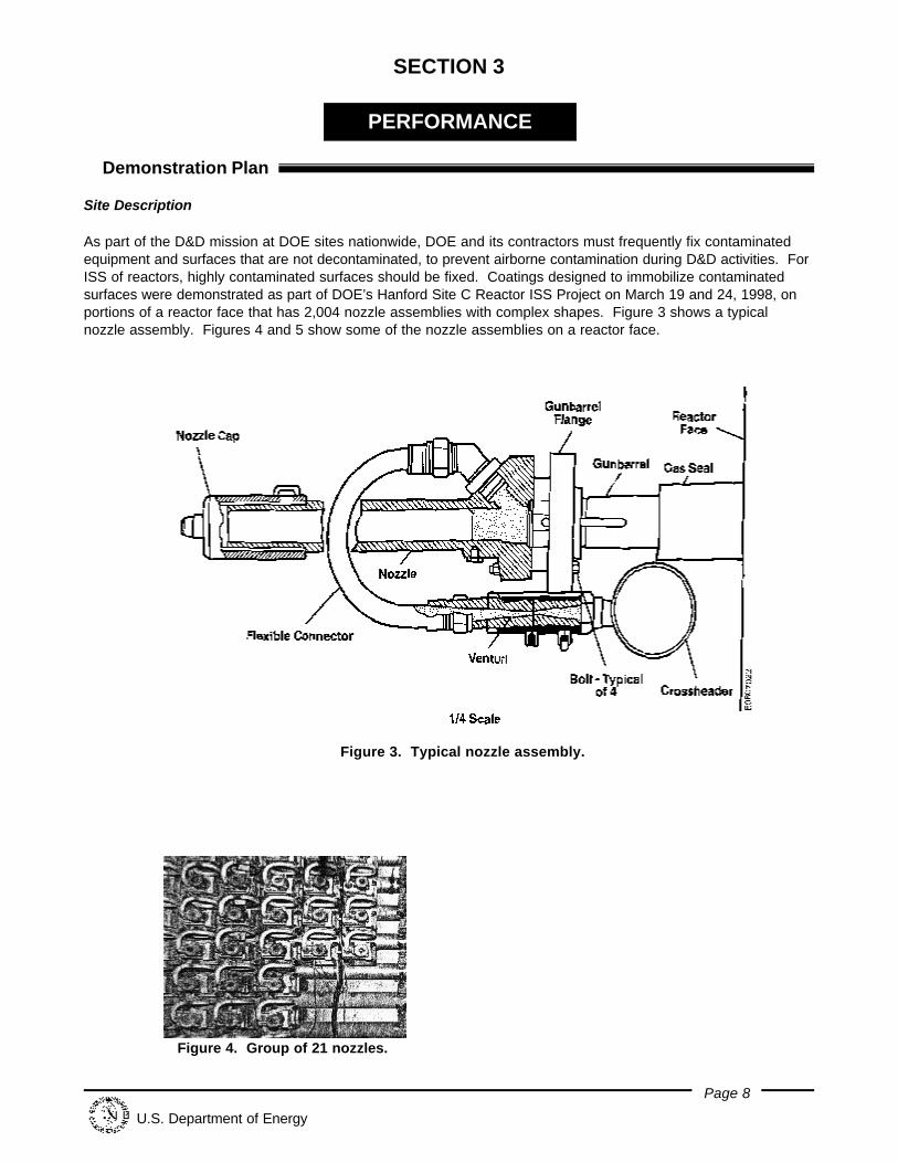
Figure 3. Typical nozzle assembly.
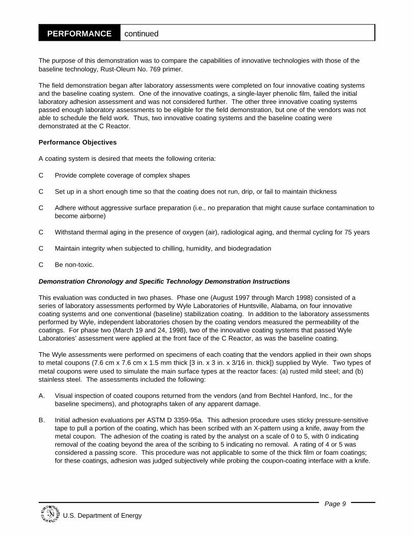
Figure 4. Group of 21 nozzles.
SECTION 3
PERFORMANCE
ê Demonstration Plan
Site Description
As part of the D&D mission at DOE sites nationwide, DOE and its contractors must frequently fix contaminatedequipment and surfaces that are not decontaminated, to prevent airborne contamination during D&D activities. ForISS of reactors, highly contaminated surfaces should be fixed. Coatings designed to immobilize contaminatedsurfaces were demonstrated as part of DOE’s Hanford Site C Reactor ISS Project on March 19 and 24, 1998, onportions of a reactor face that has 2,004 nozzle assemblies with complex shapes. Figure 3 shows a typicalnozzle assembly. Figures 4 and 5 show some of the nozzle assemblies on a reactor face.
PERFORMANCE continued
Page 9
U.S. Department of Energy
The purpose of this demonstration was to compare the capabilities of innovative technologies with those of thebaseline technology, Rust-Oleum No. 769 primer.
The field demonstration began after laboratory assessments were completed on four innovative coating systemsand the baseline coating system. One of the innovative coatings, a single-layer phenolic film, failed the initiallaboratory adhesion assessment and was not considered further. The other three innovative coating systemspassed enough laboratory assessments to be eligible for the field demonstration, but one of the vendors was notable to schedule the field work. Thus, two innovative coating systems and the baseline coating weredemonstrated at the C Reactor.
Performance Objectives
A coating system is desired that meets the following criteria:
C Provide complete coverage of complex shapes
C Set up in a short enough time so that the coating does not run, drip, or fail to maintain thickness
C Adhere without aggressive surface preparation (i.e., no preparation that might cause surface contamination tobecome airborne)
C Withstand thermal aging in the presence of oxygen (air), radiological aging, and thermal cycling for 75 years
C Maintain integrity when subjected to chilling, humidity, and biodegradation
C Be non-toxic.
Demonstration Chronology and Specific Technology Demonstration Instructions
This evaluation was conducted in two phases. Phase one (August 1997 through March 1998) consisted of aseries of laboratory assessments performed by Wyle Laboratories of Huntsville, Alabama, on four innovativecoating systems and one conventional (baseline) stabilization coating. In addition to the laboratory assessmentsperformed by Wyle, independent laboratories chosen by the coating vendors measured the permeability of thecoatings. For phase two (March 19 and 24, 1998), two of the innovative coating systems that passed WyleLaboratories’ assessment were applied at the front face of the C Reactor, as was the baseline coating.
The Wyle assessments were performed on specimens of each coating that the vendors applied in their own shopsto metal coupons (7.6 cm x 7.6 cm x 1.5 mm thick [3 in. x 3 in. x 3/16 in. thick]) supplied by Wyle. Two types ofmetal coupons were used to simulate the main surface types at the reactor faces: (a) rusted mild steel; and (b)stainless steel. The assessments included the following:
A. Visual inspection of coated coupons returned from the vendors (and from Bechtel Hanford, Inc., for thebaseline specimens), and photographs taken of any apparent damage.
B. Initial adhesion evaluations per ASTM D 3359-95a. This adhesion procedure uses sticky pressure-sensitivetape to pull a portion of the coating, which has been scribed with an X-pattern using a knife, away from themetal coupon. The adhesion of the coating is rated by the analyst on a scale of 0 to 5, with 0 indicatingremoval of the coating beyond the area of the scribing to 5 indicating no removal. A rating of 4 or 5 wasconsidered a passing score. This procedure was not applicable to some of the thick film or foam coatings;for these coatings, adhesion was judged subjectively while probing the coupon-coating interface with a knife.
PERFORMANCE continued
Page 10
U.S. Department of Energy
C. Thermal aging in an oxygen (air) atmosphere in a laboratory oven. The temperature and hours of aging werepredetermined for each coating formulation based on the Arrhenius activation energy to simulate 75 years ofaging. Visual inspection followed.
D. Radiation aging in a chamber by exposure to gamma rays from a cobalt-60 source. The thermally agedspecimens were exposed to 1560 rads, which simulates 75 years of exposure at the C Reactor face, wherethe field strength is approximately 2 mrem/hr. Another set of specimens, which had not been thermallyaged, were exposed to 10 million rads to simulate locations where the field strength is much stronger than atC Reactor. After visual inspections, another set of adhesion evaluations were performed as indicated inparagraph B above.
E. Thermal cycling in a circulating-air chamber. The thermally aged and radiation aged specimens weresubjected to 820 cycles of heating and cooling to represent extreme diurnal temperature changes historicallyexperienced at the Hanford Site. The temperature spread was automatically set at 27.8°C differential (50°Fdifferential). The selected number of cycles represents the number of times over 75 years that thetemperature spread is expected to be within 6.7°C (12°F) of the highest spread ever recorded, which wasalmost 27.8EC differential. After visual inspections, a final set of adhesion evaluations were performed asindicated in paragraph B above.
F. Chilling for 24 hours at extreme temperatures. A separate set of coated coupons were kept for more than 24hours in a chamber at -34°C (-29°F), representing the coldest temperatures on record at the Hanford Site. This was also followed by visual inspection.
G. Humidity exposure per ASTM D 2247-94. The specimens chilled in step F were maintained for a week in achamber with 100% relative humidity. The effect of humidity was evaluated by measuring the spread of rustthat formed at the interface of a coating and a mild steel coupon surface. After visual inspections, a final setof adhesion evaluations were performed as indicated in paragraph B above.
H. Biodegradation assessments per a modified version of ASTM G 22-76. Separate specimens were incubatedwith bacteria that had been cultured from a sample of soil obtained near the Hanford Site C Reactor. Theincubation was in a high humidity atmosphere at 25°C (77°F) for 21 days. Modifications to the standardASTM procedure were made so that the elevated temperatures would not prevent bacterial growth.
I. Density measurements per ASTM D 792-91. The densities of the various coatings were measured usingunaged materials only so that the added weight could be estimated if the front and rear reactor faces werecoated.
J. Permeability measurements on aged samples. The permeability measurements apply only to film samplesthat were not on metal coupons. Wyle aged the samples thermally and radiologically and sent them alongwith unaged samples to independent laboratories designated by the various coating vendors. The aged andunaged samples were each measured for water vapor transmission per ASTM D 1653-93, and for airpermeability per ASTM D 1434.
Once the laboratory assessments were completed, the vendors of those coatings that passed the assessmentswere invited to demonstrate their technologies at the C Reactor. Three of the four coatings passed theassessments; of those three only two (RedHawk Environmental, Inc., and Master-Lee Engineering) were able toschedule demonstrations. Their technologies were applied to the reactor face along with the baseline technology.
Each promising coating system and the baseline coating were applied at different locations on the C Reactor frontface to cover an array of complex-shaped, congested nozzle assemblies on a portion of face area. After theapplication, the coating thickness and completeness of coverage were evaluated. In addition, the equipment setuptime, application time, cure time, and demobilization time were recorded.
PERFORMANCE continued
Page 11
U.S. Department of Energy
ê Technology Demonstration Results
Key Demonstration Results
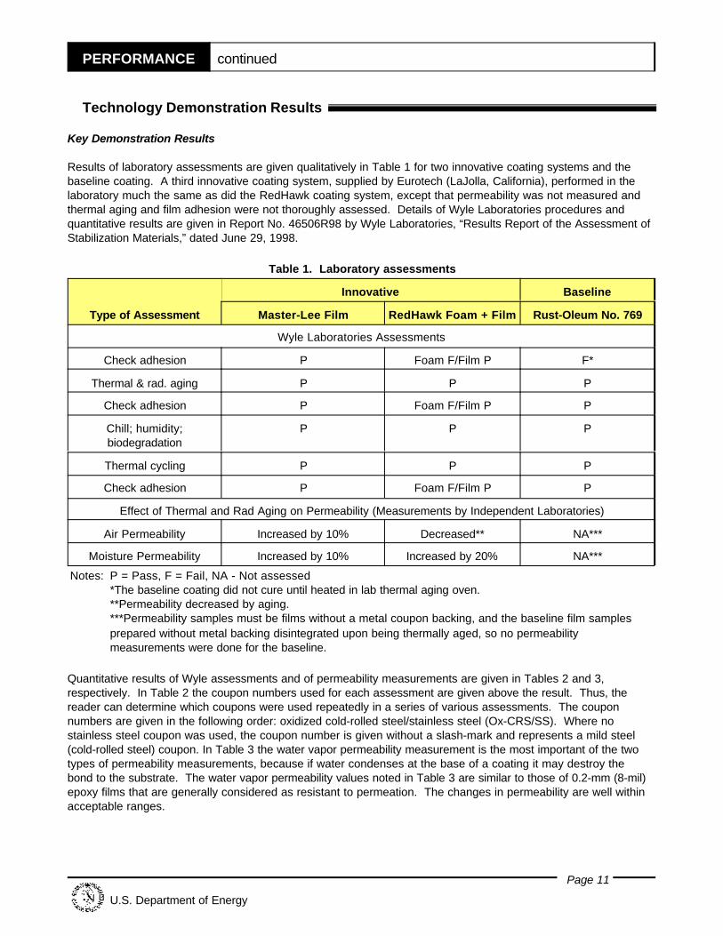
Results of laboratory assessments are given qualitatively in Table 1 for two innovative coating systems and thebaseline coating. A third innovative coating system, supplied by Eurotech (LaJolla, California), performed in thelaboratory much the same as did the RedHawk coating system, except that permeability was not measured andthermal aging and film adhesion were not thoroughly assessed. Details of Wyle Laboratories procedures andquantitative results are given in Report No. 46506R98 by Wyle Laboratories, “Results Report of the Assessment ofStabilization Materials,” dated June 29, 1998.
Table 1. Laboratory assessments
Type of Assessment
Innovative Baseline
Master-Lee Film RedHawk Foam + Film Rust-Oleum No. 769
Wyle Laboratories Assessments
Check adhesion P Foam F/Film P F*
Thermal & rad. aging P P P
Check adhesion P Foam F/Film P P
Chill; humidity;biodegradation
P P P
Thermal cycling P P P
Check adhesion P Foam F/Film P P
Effect of Thermal and Rad Aging on Permeability (Measurements by Independent Laboratories)
Air Permeability Increased by 10% Decreased** NA***
Moisture Permeability Increased by 10% Increased by 20% NA***
Notes: P = Pass, F = Fail, NA - Not assessed*The baseline coating did not cure until heated in lab thermal aging oven.**Permeability decreased by aging.***Permeability samples must be films without a metal coupon backing, and the baseline film samplesprepared without metal backing disintegrated upon being thermally aged, so no permeabilitymeasurements were done for the baseline.
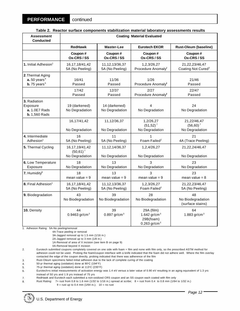
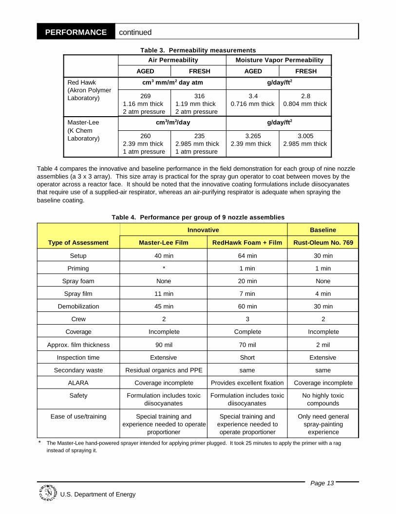
Quantitative results of Wyle assessments and of permeability measurements are given in Tables 2 and 3,respectively. In Table 2 the coupon numbers used for each assessment are given above the result. Thus, thereader can determine which coupons were used repeatedly in a series of various assessments. The couponnumbers are given in the following order: oxidized cold-rolled steel/stainless steel (Ox-CRS/SS). Where nostainless steel coupon was used, the coupon number is given without a slash-mark and represents a mild steel(cold-rolled steel) coupon. In Table 3 the water vapor permeability measurement is the most important of the twotypes of permeability measurements, because if water condenses at the base of a coating it may destroy thebond to the substrate. The water vapor permeability values noted in Table 3 are similar to those of 0.2-mm (8-mil)epoxy films that are generally considered as resistant to permeation. The changes in permeability are well withinacceptable ranges.
PERFORMANCE continued
Page 12
U.S. Department of Energy
Table 2. Reactor surface components stabilization material laboratory assessments resultsAssessmentConducted
Coating Material Evaluated
RedHawk Master-Lee Eurotech EKOR Rust-Oleum (baseline)
Coupon #Ox-CRS / SS
Coupon #Ox-CRS / SS
Coupon #Ox-CRS / SS
Coupon #Ox-CRS / SS
1. Initial Adhesion1
16,17,18/41,425A (No Peeling)
11,12,13/36,375A (No Peeling)
1,2,3/26,27Procedure Anomaly2
21,22,23/46,47Coating Not Cured3
2.Thermal Aging a. 50 years4
b. 75 years516/41
Passed11/36
Passed1/26
Procedure Anomaly621/46
Passed
17/42Passed
12/37Passed
2/27Procedure Anomaly6
22/47Passed
3. RadiationExposure a. 1.0E7 Rads b. 1,560 Rads
19 (darkened)No Degradation
14 (darkened)No Degradation
4No Degradation
24No Degradation
16,17/41,42
No Degradation
11,12/36,37
No Degradation
1,2/26,27(51,52) 7
No Degradation
21,22/46,47(56,60) 7
No Degradation
4. Intermediate Adhesion1
165A (No Peeling)
115A (No Peeling)
1Foam Failed2
214A (Trace Peeling)
5. Thermal Cycling 16,17,19/41,42(50,61) 7
No Degradation
11,12,14/36,37
No Degradation
1,2,4/26,27
No Degradation
21,22,24/46,47
No Degradation
6. Low Temperature Exposure
18No Degradation
13No Degradation
3No Degradation
23No Degradation
7. Humidity8 18mean value = 9
13mean value = 9
3mean value = 9
23mean value = 8
8. Final Adhesion1 16,17,18/41,425A (No Peeling)
11,12,13/36,375A (No Peeling)
1,2,3/26,27Foam Failed2
21,22,23/46,475A (No Peeling)
9. Biodegradation 43No Biodegradation
39No Biodegradation
28No Biodegradation
48No Biodegradation
(surface stains)
10. Density 440.9463 gr/cm3
390.897 gr/cm3
29A (film)1.642 gr/cm3
29B(foam)0.263 gr/cm3
641.883 gr/cm3
1. Adhesion Rating: 5A-No peeling/removal 4A-Trace peeling or removal 3A-Jagged removal up to 1.5 mm (1/16 in.) 2A-Jagged removal up to 3 mm (1/8 in.)
1A-Removal of area of X incision (see item B on page 9) 0A-Removal beyond X incision
2. Eurotech submitted coupons completely covered on one side with foam + film and none with film only, so the prescribed ASTM method foradhesion could not be used. Probing the foam/coupon interface with a knife indicated that the foam did not adhere well. Where the film overlaycontacted the edge of the coupon directly, probing indicated that there was adherence of the film
3. Rust-Oleum specimens failed initial adhesion due to the lack of complete curing of the coating4. 50-yr thermal aging (oxidation) done at 90oC (1940 F) 5. 75-yr thermal aging (oxidation) done at 113oC (2350 F) 6. Eurotech=s initial measurements of activation energy was 1.4 eV versus a later value of 0.90 eV resulting in an aging equivalent of 1.3 yrs
instead of 50 yrs and 1.9 yrs instead of 75 yrs7. RedHawk and Eurotech each submitted a non-oxidized CRS coupon and an SS coupon each coated with film only8. Rust Rating: 7= rust from 0.8 to 1.6 mm (1/32 to 1/16 in.) spread at scribe; 8 = rust from 0.4 to 0.8 mm (1/64 to 1/32 in.)
9 = rust up to 0.4 mm (1/64 in.); 10 = no rust
PERFORMANCE continued
Page 13
U.S. Department of Energy
Table 3. Permeability measurements
Air Permeability Moisture Vapor Permeability
AGED FRESH AGED FRESH
Red Hawk(Akron PolymerLaboratory)
cm3 mm/m2 day atm g/day/ft2
2691.16 mm thick2 atm pressure
3161.19 mm thick2 atm pressure
3.40.716 mm thick
2.80.804 mm thick
Master-Lee (K ChemLaboratory)
cm3/m2/day g/day/ft2
2602.39 mm thick1 atm pressure
2352.985 mm thick1 atm pressure
3.2652.39 mm thick
3.0052.985 mm thick
Table 4 compares the innovative and baseline performance in the field demonstration for each group of nine nozzleassemblies (a 3 x 3 array). This size array is practical for the spray gun operator to coat between moves by theoperator across a reactor face. It should be noted that the innovative coating formulations include diisocyanatesthat require use of a supplied-air respirator, whereas an air-purifying respirator is adequate when spraying thebaseline coating.
Table 4. Performance per group of 9 nozzle assemblies
Type of Assessment
Innovative Baseline
Master-Lee Film RedHawk Foam + Film Rust-Oleum No. 769
Setup 40 min 64 min 30 min
Priming * 1 min 1 min
Spray foam None 20 min None
Spray film 11 min 7 min 4 min
Demobilization 45 min 60 min 30 min
Crew 2 3 2
Coverage Incomplete Complete Incomplete
Approx. film thickness 90 mil 70 mil 2 mil
Inspection time Extensive Short Extensive
Secondary waste Residual organics and PPE same same
ALARA Coverage incomplete Provides excellent fixation Coverage incomplete
Safety Formulation includes toxicdiisocyanates
Formulation includes toxicdiisocyanates
No highly toxiccompounds
Ease of use/training Special training andexperience needed to operate
proportioner
Special training andexperience needed tooperate proportioner
Only need generalspray-painting
experience
* The Master-Lee hand-powered sprayer intended for applying primer plugged. It took 25 minutes to apply the primer with a raginstead of spraying it.
PERFORMANCE continued
Page 14
U.S. Department of Energy
Successes
C The innovative polyurea film sets up almost immediately and adheres.
C When the foam is used as an undercoat, it expands upon application and completely covers enough of thecomplex shapes so that the film overcoat can easily be applied with 100% coverage.
C The film forms a low-permeability layer over the foam, and the film can adhere the coating system to thereactor face and to nozzle ends that protrude out from the foam.
C Inspection of the foam + film system for quality control is simple.
C The foam + film system provides coverage of complex shapes and acceptable adherence.
C The innovative coating systems have the ability to adhere and to harden in a short time; withstand aging andthermal cycling up to 75 years; and maintain integrity when subjected to chilling, humidity, and potentialbiodegradation.
C The innovative coating systems are simple to deploy, but require some special worker experience with theproportioning equipment.
C The foam + film system provides long-term ALARA better than the baseline by achieving fixation withcomplete coverage.
Shortfalls
C Both film-only coating systems, the innovative Master-Lee polymer and the baseline Rust-Oleum No. 769primer, failed to cover the nozzle assemblies completely. The backsides of flanges and parts of curved,braided stainless steel hoses could not be reached by the spray gun.
C Overall time (equipment setup, application, and demobilization) for the innovative coatings technology wastwo-and-one-half times longer than the baseline technology.
The baseline coating cured too slowly to perform initial laboratory assessments such as adhesion, and remaineduncured until thermal aging started.
Meeting Performance Objectives
The Red Hawk coating system met the performance objectives, except for toxicity risks while spraying. Thesingle-layer systems did not completely cover complex shapes, based on the application method.
ê Comparison of Innovative Technology with Baseline
The baseline demonstration consisted of Rust-Oleum No. 769 damproof red primer applied with a conventionalairless paint-spray pump and gun. The film thickness should be approximately 0.05 mm (2 mils) thick. Theprimer was mixed at the pump and delivered to the spray gun via hoses. During the application of this coating,only one member of the two-person crew was in full PPE with an air-purifying respirator (APR). The baselinecoating failed the initial adhesion laboratory assessment because the coating had not cured. When unsupportedfilm samples were thermally aged by Wyle Laboratories in preparation for permeability measurements, thesamples disintegrated, so permeability measurements were not made for the baseline coating. In thedemonstration at the front face of the C Reactor block, the baseline coating was applied without a foam underlayerand failed to cover all of the complex shapes of the nozzle assemblies, just as occurred with the innovativeMaster-Lee film-only application.
PERFORMANCE continued
Page 15
U.S. Department of Energy
Also, the foam is somewhat held in place by the complex shapes (nozzle assemblies) that are permanentlyattached to the reactor face, because the foam is placed around and in between the complex shapes.
Foam samples were submitted by RedHawk and Eurotech for assessments by Wyle Laboratories. None of thefoams adhered to the metal coupons. However, adherence of foam is not considered necessary if it is covered bya suitable film layer that overlaps edges of the foam onto nozzle ends and onto the reactor face and providesoverall adherence of the two-layer coating system. The foam samples and three of the four innovative film samplespassed enough laboratory assessments to be eligible for the field demonstration. However, Eurotech was not ableto schedule a field demonstration, so its coating system was not evaluated at the reactor.
After thermal aging, the baseline coating passed the laboratory assessments and was also eligible for the fielddemonstration.
The innovative film coatings are polymeric formulations that are applied in thicknesses that are 35 to 45 times thethickness of the baseline coating. Such thick polymeric films harden very quickly into durable, elastic coatings, incontrast to the baseline coating, which cannot cure properly or maintain even thickness when applied heavily.
Skills/Training
Workers must be able to operate paint spray guns and air compressors. The innovative coatings require thatoperators have special training and experience and supervised experience with multi-component proportioningequipment.
Operational Concerns
C The film-only coatings would be very difficult and tedious to inspect for quality control where there arecongested piping arrangements as at the reactor front face, whereas a foam + film system would needrelatively simple inspection, mainly where the film overlaps beyond the foam.
C Respiratory protection must be worn when applying the coatings.
C In radiologically contaminated areas, standard radiological work practices and engineering controls must beused to prevent the operating personnel or any part of the work area from becoming contaminated.
Page 16
U.S. Department of Energy
SECTION 4
TECHNOLOGY APPLICABILITYAND ALTERNATIVE
TECHNOLOGIES
ê Technology Applicability
C The polyurethane foam and polyurea film are ideally suited for any D&D activities that require fixation ofcontaminated equipment, walls, floors, and ceilings, especially where thick, durable coatings are desired thatare resistant to oxidation and radioactive aging. Prior small-scale demonstrations indicated that polyureafilm is resistant to abrasion, hydrophobic, and useful for radioactive debris transport vehicle liners, buildingroof components, and valve pits. This is also a very effective encapsulant for lead, lead-based paint, andasbestos. It can be used as a pond liner or spill barrier and secondary containment for aggressive chemicalgroups, including acids, alkalis, salts, oils, solvents, refined petrochemical products, and polychlorinatedbiphenyls (PCBs).
C This technology is potentially valuable for any D&D project, and it is of particular value at sites whereequipment may be either internally or externally contaminated. The applications of foams and films is auseful alternative in environments where airborne contamination caused by D&D operations is notacceptable.
C The DOE, the U.S. Nuclear Regulatory Commission, and the U.S. Environmental Protection Agency all havepotentially wide use of this technology at nuclear facilities under their jurisdiction. Private-sector remediationand demolition contractors will also be interested.
ê Competing Technologies
C A number of commercially available polymeric coatings with good resistance to aging can compete withpolyurea films. Where complex shapes are to be coated and a base layer of foam is needed, comparablespray-on foams may work as well as polyurethane. If the foam is completely covered by a film, as in thisdemonstration, the foam does not need to be resistant to aging provided that the film is thick (at least1.8 mm or 70 mils), tough, and elastic, as were both polyurea films demonstrated.
C The silicon-based foam and film submitted by Eurotech were developed for use at Chornobyl and performedwell during the laboratory phase of this demonstration. Eurotech was not able to schedule the second-phaseapplication at the C Reactor face, but it is likely that the Eurotech foam and film system would havesucceeded in the field demonstration and the system does not involve highly toxic substances such asdiisocyanates that comprise part of polyurea and polyurethane formulations.
ê Patents/Commercialization/Sponsors
The application equipment is commercially available. The polyurea formulation is licensed by Huntsman ChemicalCorporation. Polyurethane foam is commercially available.
Page 17
U.S. Department of Energy
SECTION 5
COST
ê Introduction/Methodology
This section provides a cost analysis for the successful innovative (RedHawk) technology and the baseline(Rust-Oleum) technology that use fixative coatings to stabilize radiologically contaminated surfaces, such aswould be left behind during interim safe storage at the Hanford Site C Reactor. This analysis determined that thebaseline is approximately 30% of the cost of the innovative technology. However, the innovative polymeric filmsare the more applicable method to use for reactor surface contaminant stabilization, because the polymeric filmsare thick and durable. By applying such films over foam, complete coverage is attained for long-term stabilization. The baseline technology does not completely cover complex surfaces unless the application method is modified.
The baseline and innovative technology costs are from direct observations of coating an array of reactor nozzles on part of the reactor face. The observed production rates from the demonstration form the basis of a costanalysis for 2,004 reactor nozzles covering the entire face of the reactor, an area of 196.6 m2 (2,116 ft2). Thebaseline technology uses a paint spray pump (where the coating is mixed) connected via a hose to a spray gun. The innovative technology assumes a vendor-provided service using a Gusmer Model H-3500 high-pressureproportioner that controls the mixture of the coating compounds and delivers it via two hoses to a Gusmer ModelNo. GX-7 spray gun. Prior to the demonstration application, the baseline and innovative coatings were applied to7.6-cm x 7.6-cm (3-in. x 3-in.) metal coupons and shipped to Wyle Laboratories for a series of assessments. Such laboratory assessments are not included in this cost analysis.
Cost Data
The baseline technology uses commercially available equipment (airless paint spray pump and gun), but theinnovative technology uses equipment (Gusmer Model H-3500 high-pressure proportioner) that is rented fromRedHawk Environmental at a rate of $500 per day, and includes the spray gun, hose, air compressor, and trailer. This rate was converted to an hourly rate for the estimates. The raw materials for priming, foam, and film coatingfor the innovative technology and primer plus film coating for the baseline technology were based on vendorquotes. The material costs for the Rust-Oleum No. 769 used in the baseline technology is $9.36 per liter ($35.41per gallon). In the innovative technology, the polyurethane foam is $3 per kilogram ($1.74 per pound) and thepolyurea film is $140 per kilogram ($63.50 per pound).
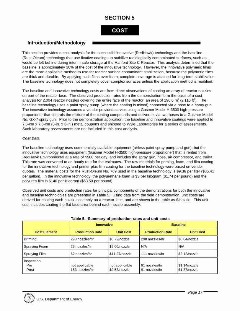
Observed unit costs and production rates for principal components of the demonstrations for both the innovativeand baseline technologies are presented in Table 5. Using data from the field demonstration, unit costs arederived for coating each nozzle assembly on a reactor face, and are shown in the table as $/nozzle. This unitcost includes coating the flat face area behind each nozzle assembly.
Table 5. Summary of production rates and unit costs
Cost Element
Innovative Baseline
Production Rate Unit Cost Production Rate Unit Cost
Priming 298 nozzles/hr $0.72/nozzle 298 nozzles/hr $0.64/nozzle
Spraying Foam 25 nozzles/hr $9.00/nozzle N/A N/A
Spraying Film 62 nozzles/hr $11.27/nozzle 111 nozzles/hr $2.12/nozzle
Inspection Pre Post
not applicable153 nozzles/hr
not applicable$0.53/nozzle
91 nozzles/hr91 nozzles/hr
$1.14/nozzle$1.37/nozzle
COST continued
Page 18
U.S. Department of Energy
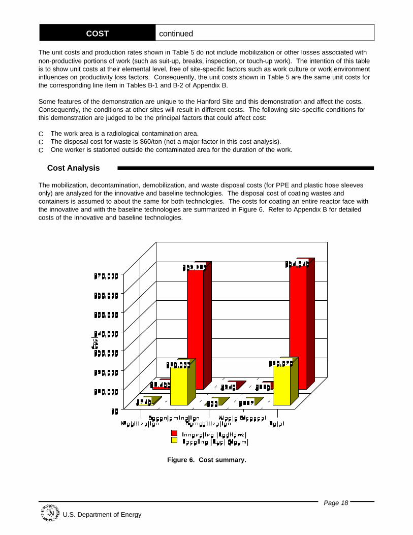
Figure 6. Cost summary.
The unit costs and production rates shown in Table 5 do not include mobilization or other losses associated withnon-productive portions of work (such as suit-up, breaks, inspection, or touch-up work). The intention of this tableis to show unit costs at their elemental level, free of site-specific factors such as work culture or work environmentinfluences on productivity loss factors. Consequently, the unit costs shown in Table 5 are the same unit costs forthe corresponding line item in Tables B-1 and B-2 of Appendix B.
Some features of the demonstration are unique to the Hanford Site and this demonstration and affect the costs. Consequently, the conditions at other sites will result in different costs. The following site-specific conditions forthis demonstration are judged to be the principal factors that could affect cost:
C The work area is a radiological contamination area.C The disposal cost for waste is $60/ton (not a major factor in this cost analysis).C One worker is stationed outside the contaminated area for the duration of the work.
ê Cost Analysis
The mobilization, decontamination, demobilization, and waste disposal costs (for PPE and plastic hose sleevesonly) are analyzed for the innovative and baseline technologies. The disposal cost of coating wastes andcontainers is assumed to about the same for both technologies. The costs for coating an entire reactor face withthe innovative and with the baseline technologies are summarized in Figure 6. Refer to Appendix B for detailedcosts of the innovative and baseline technologies.
COST continued
Page 19
U.S. Department of Energy
ê Cost Conclusions
The major cost drivers for the innovative technology are:
C Material costs for the polyurea filmC Spraying the foam C Spraying the filmC Lost timeC Donning and doffing PPE C Material costs of the PPE.
The baseline has the same cost drivers except for the polyurea film material costs, plus inspecting the coating andtouch-up. (Inspection and touch-up needs are much less with the innovative foam and film coating system. The foamlayer results in smooth surface with reduced area that is easy to see and reach.) The baseline avoids the cost of thefoam application, and it also has a production rate for spraying the film that is almost twice the rate of the innovativetechnology. The labor rates, equipment rates, and the material costs for the innovative technology are another reasonfor the higher costs of the innovative technology. The labor and equipment costs for the innovative technology are morethat twice the cost of the baseline. The material costs for the innovative technology are seven times the cost of thebaseline. This may be offset if local craft workers can be used and as experience with the work is gained. Theproduction rate increases and the quantity of foam used is decreased as workers become experienced in bridging thefoam over large voids. The vendor believes that the observed production rates may be innovative by as much as 40%with experience, which would be gained rapidly after several groups of nozzles are coated during a project thatencompasses stabilization of an entire reactor face.
The chemicals used by the innovative technology affect PPE requirements. The baseline technology uses an APR,while the innovative technology uses a supplied-air respirator, which includes additional cost for a breathing-aircompressor attended by an industrial hygienist (IH). These additional costs are included under the IH hourly rate of$54.77 per hour shown in Table B-1 of Appendix B.
The readers can estimate their costs by inserting their site-specific quantities into the tables in Appendix C. Thetables are based on the quantities required per nozzle assembly. For complex shapes and distances betweenassemblies that are different than at the C Reactor face, the paragraph in Appendix C headed “Spray Foam” gives thefoam quantity used per group of nine nozzle assemblies. This quantity can be adjusted based on 0.74 m2 (0.8 ft2) offace area per group foamed to a depth of about 50 cm (20 in.). However, the reader is cautioned that foam does nothave to fill all voids and that cavities may be left within the foam, with commensurate cost savings. The volume ofcavities would be higher for complex shapes that are closer than the approximate 30 cm (12 in.) between nozzleassemblies. The volume of cavities would be less for wider spacing.
Page 20
U.S. Department of Energy
SECTION 6
REGULATORY/POLICY ISSUES
ê Regulatory Considerations
C No special regulatory permits are required for applying coatings to stabilize contamination.
C The technology can be used in daily operation under the requirements of 10 CFR, Parts 20, 835, andproposed 834 for protection of workers and the environment from radiological contaminants; and 29 CFR,OSHA worker requirements.
C Although the demonstration took place at a Comprehensive Environmental Response, Compensation, andLiability Act (CERCLA) site, no CERCLA requirements apply to the stabilization of above-ground reactor blockcomponents.
ê Safety, Risk, Benefits, and Community Reaction
Worker Safety
C Radiation protection worker safety instructions already in use at the facility apply.
C The user of the technology must use contamination control practices when applying coatings.
C Normal worker safety precautions and practices prescribed by OSHA for equipment operation (especiallycompressors) must be followed. Use of proper respiratory protection is needed when spraying formulationsthat contain diisocyanates.
Community Safety
C It is not anticipated that implementation of the innovative technology would present any adverse impacts tocommunity safety.
ê Environmental Impact
C It is not anticipated that implementation of the innovative technology would present any adverse impacts to theenvironment.
ê Socioeconomic Impacts and Community Perception
C No socioeconomic impacts are expected with the use of this technology.
Page 21
U.S. Department of Energy
SECTION 7
LESSONS LEARNED
ê Implementation
C Coatings reduce the risk of creating airborne contamination while D&D work, such as cutting, dismantling anddisassembly, is performed, or the coatings enhance interim safe storage.
ê Technology Limitations/Needs for Future Development
C Currently, there is no need to modify the two-layer innovative technology demonstrated at the Hanford SiteC Reactor.
C Film-only systems would need multi-directional spray tips to cover the backside of complex shapes. Alternative methods of achieving coverage by one-layer systems might include attaching a mesh or screen ora rigid cover over the reactor face nozzle assemblies end caps. Then a film could be sprayed over the entiremesh or over the rigid cover joints.
C The demonstration was carried out in a low-radiation field (<2 mrem/hr). In a high-radiation situation, theapplication of foam should be done with a remotely controlled spray gun instead of with the hand-held spraygun demonstrated.
C The maximum distance between the proportioner and the spray tip (maximum length of hose runs) is 91.5 m(300 ft). This is a design limitation based on the rating of the electrical transformer that energizes the hoseheating system.
ê Technology Selection Considerations
C The technology is suitable for DOE nuclear facilities or any other sites where radioactive or chemicalcontamination must be stabilized.
C The polyurea film alone is suitable where direct spraying on the surface to be stabilized is possible, such asflat surfaces or places with open access. For complex or congested equipment shapes, the use of a foambase layer should be considered.
C Where a non-toxic foam + film application is required, the Eurotech (La Jolla, California) coating system couldbe considered (but was not field-demonstrated).
Page 22
U.S. Department of Energy
APPENDIX A
REFERENCES
10 CFR Part 835, “Occupational Radiation Protection,” as amended.
Proposed 10 CFR Part 834, "Environmental Radiation Protection,” as proposed.
10 CFR Part 20, "Occupational Radiation Protection,” as amended.
29 CFR Part 1910, “General Industry Occupational Safety and Health Standards,” as amended.
29 CFR Part 1926, “Construction Occupational Safety and Health Standards,” as amended.
Means Construction Equipment Cost Data, R. S. Means Co., Kingston, Massachusetts, 1997.
USACE, 1996, Hazardous, Toxic, Radioactive Waste Remedial Action Work Breakdown Structure and DataDictionary, U.S. Army Corps of Engineers, Washington, D.C.
Wyle Laboratories, “Results Report of the Assessment of Stabilization Materials for Use at the U.S. Department ofEnergy Hanford Site,” Report No. 46506R98, Job 46506, June 29, 1998, Huntsville, Alabama.
Page 23
U.S. Department of Energy
APPENDIX B
COST COMPARISON
ê Introduction
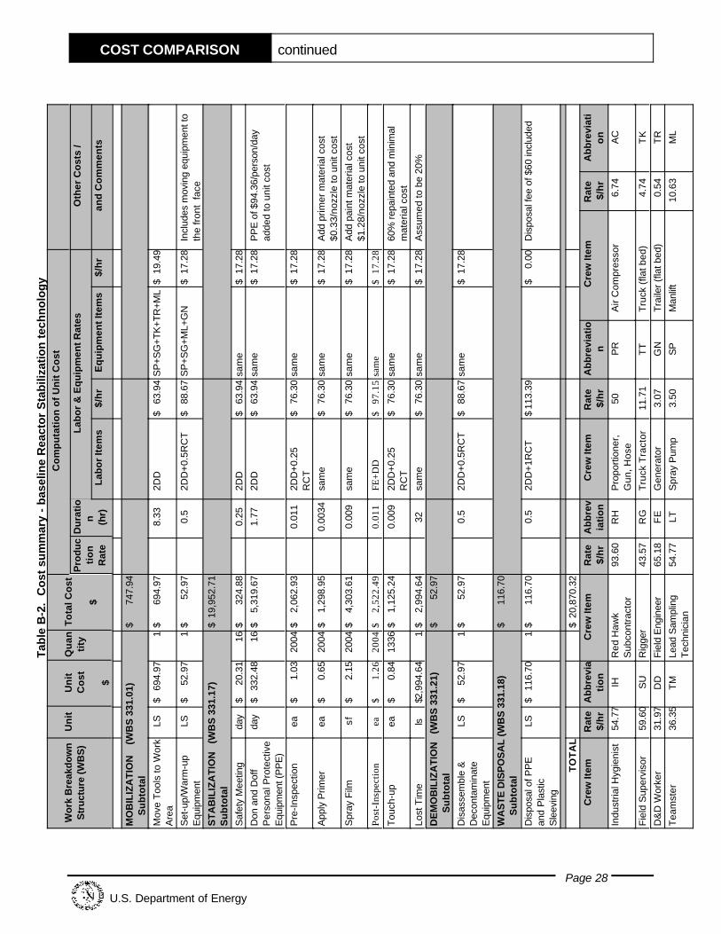
The cost effectiveness analysis computes the cost for fixative coatings applied for reactor surface contaminationstabilization using hourly rates for equipment and labor observed in the course of demonstrating the innovative two-layer technology and the baseline technology for nine nozzle assemblies each. The observed production ratesand durations were extrapolated to the entire reactor face, which consists of a 46-ft x 46-ft area with2,004 nozzles. The extrapolation includes additional time for repositioning a manlift, because a manlift (orscaffolding) is required for working on the reactor face above the first several rows of nozzles. The analysisassumes that the innovative technology work is performed as a vendor-provided service (vendor-owned equipmentand personnel).
The selected basic activities being analyzed come from the Hazardous, Toxic, Radioactive Waste RemedialAction Work Breakdown Structure and Data Dictionary (HTRW RA WBS), USACE, 1996. The HTRW RA WBS,developed by an interagency group, is used in this analysis to provide consistency with established nationalstandards.
Some costs are omitted from this analysis to make it easier to understand and to facilitate comparison with costsfor the individual site. The overhead and general and administrative (G&A) markup costs for the site contractormanaging the demonstration are omitted from this analysis. Overhead and G&A rates for each DOE site vary inmagnitude and in the way they are applied. Decision makers seeking site-specific costs can apply their site’srates to this analysis without having to first back-out the rates used at the Hanford Site.
The following assumptions were used as the basis of the cost analysis for the innovative technology:
C Oversight engineering, quality assurance, and administrative costs for the demonstration are not included. These are normally covered by another cost element, generally as an undistributed cost.
C The procurement cost of 7.5% was applied to all purchased equipment so that the costs of administering thepurchase are accounted for (this cost is included in the hourly rate).
C The equipment hourly rates for the site-owned equipment that may be used in support of the innovativeequipment (e.g., the site-owned truck that transports the rented innovative equipment from the warehousereceiving to the C Reactor) uses standard equipment rates established at the Hanford Site.
C The equipment hourly rates for the Gusmer Model H-3500 high-pressure proportioner are based on a rentalrate and operation cost from vendor quotes (no standard site rates for the proportioner were available).
C The standard labor rates established by the Hanford Site for estimating D&D work are used in this analysis forthe portions of the work performed by local crafts.
C The analysis uses a 10-hour work day.
C Material costs for the primer, foam, and film for the innovative technology and primer plus film for the baselinetechnology are based on vendor quotes.
MOBILIZATION (WBS 331.01)
Move Tools to Work Area: The observed time required, based on previous deployments, for retrieving the spraypump, spray gun, and other tools and equipment for the baseline technology from storage and moving them to thework area was used for both the innovative and baseline technologies and also considered the observed timerequired for the vendor to mobilize onsite for the innovative technology.
COST COMPARISON continued
Page 24
U.S. Department of Energy
Sleeve Hose/Set-up Equipment: This activity applies only to the innovative technology and is based on observedduration. Hoses are sleeved with plastic film.
Setup/Warmup Equipment: This activity includes preparing the paint spray pump and gun for the baselinetechnology, and includes connecting the hoses to the spray gun for both technologies. Warm-up applies only tothe proportioning procedure used with the innovative technology.
Pre-Test Equipment: This activity applies only to the innovative technology and is based on observed duration.
STABILIZATION (WBS 331.17)
Safety Meeting: The baseline work required a safety meeting for each morning following the first day of work. The costs for the innovative technology were assumed to be similar to the observed duration for the baseline.
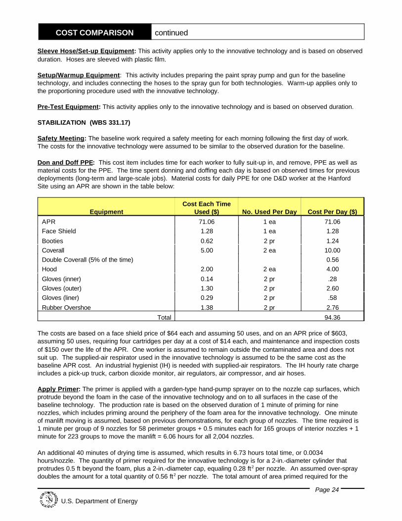
Don and Doff PPE: This cost item includes time for each worker to fully suit-up in, and remove, PPE as well asmaterial costs for the PPE. The time spent donning and doffing each day is based on observed times for previousdeployments (long-term and large-scale jobs). Material costs for daily PPE for one D&D worker at the HanfordSite using an APR are shown in the table below:
EquipmentCost Each Time
Used ($) No. Used Per Day Cost Per Day ($)
APR 71.06 1 ea 71.06Face Shield 1.28 1 ea 1.28
Booties 0.62 2 pr 1.24Coverall 5.00 2 ea 10.00Double Coverall (5% of the time) 0.56Hood 2.00 2 ea 4.00
Gloves (inner) 0.14 2 pr .28Gloves (outer) 1.30 2 pr 2.60Gloves (liner) 0.29 2 pr .58
Rubber Overshoe 1.38 2 pr 2.76
Total 94.36
The costs are based on a face shield price of $64 each and assuming 50 uses, and on an APR price of $603,assuming 50 uses, requiring four cartridges per day at a cost of $14 each, and maintenance and inspection costsof $150 over the life of the APR. One worker is assumed to remain outside the contaminated area and does notsuit up. The supplied-air respirator used in the innovative technology is assumed to be the same cost as thebaseline APR cost. An industrial hygienist (IH) is needed with supplied-air respirators. The IH hourly rate chargeincludes a pick-up truck, carbon dioxide monitor, air regulators, air compressor, and air hoses.
Apply Primer: The primer is applied with a garden-type hand-pump sprayer on to the nozzle cap surfaces, whichprotrude beyond the foam in the case of the innovative technology and on to all surfaces in the case of thebaseline technology. The production rate is based on the observed duration of 1 minute of priming for ninenozzles, which includes priming around the periphery of the foam area for the innovative technology. One minuteof manlift moving is assumed, based on previous demonstrations, for each group of nozzles. The time required is1 minute per group of 9 nozzles for 58 perimeter groups + 0.5 minutes each for 165 groups of interior nozzles + 1minute for 223 groups to move the manlift = 6.06 hours for all 2,004 nozzles.
An additional 40 minutes of drying time is assumed, which results in 6.73 hours total time, or 0.0034hours/nozzle. The quantity of primer required for the innovative technology is for a 2-in.-diameter cylinder thatprotrudes 0.5 ft beyond the foam, plus a 2-in.-diameter cap, equaling 0.28 ft2 per nozzle. An assumed over-spraydoubles the amount for a total quantity of 0.56 ft2 per nozzle. The total amount of area primed required for the
COST COMPARISON continued
Page 25
U.S. Department of Energy
innovative technology is 0.56 ft2 per nozzle, which is 1,122 ft2 for 2,004 nozzles, plus primer for the border area,which adds approximately 184 ft2 for an area of 1,306 ft2 per 2,004 nozzles, or 0.652 ft2 per nozzle. The materialcost is $63.50/gal, and at a 1-mil thickness the material will cover 560 ft2 for a cost of $0.113/ft2. The cost pernozzle is 0.652 ft2 at $0.113 ft2, or $0.07/nozzle for the innovative technology.
The time required to apply the primer for the baseline technology is assumed to be the same as for the innovativetechnology. The material costs for the baseline’s primer is $35.41/gal and is assumed to cover 560 ft2 (this isassumed to be the same as for the innovative technology) for a cost of $0.063/ ft2. The surface area primed for thebaseline technology is the face of the reactor (46 ft x 46 ft) plus the gas seal, gunbarrel, flange, venturi,crossheader, and nozzle, which is a total of 4.19 ft2/nozzle. The total area for the baseline technology is 46 ft x 46ft + (4.19 ft2 x 2004 nozzles), or 10,513 ft2 for all nozzles or 5.25 ft2/nozzle. The primer per nozzle for the baselineis $0.063 ft2 x 5.25 ft2/nozzle = $0.33/nozzle.
Spray Foam: The Gusmer Model H-3500 high-pressure proportioner controls the mixture of the polyurethanefoam compounds and delivers the mixture to the Gusmer Model No. GX-7 spray gun for application. The observedduration for nine nozzles was 20 minutes or 2.22 min/nozzle. An additional time is assumed for repositioning themanlift (1 minute for each group of nozzles, or 223 groups of 9 nozzles x 1 minute equals 3.7 hours). The totaltime required is 3.7 hours + 2.22 min/nozzle x 2,004 nozzles equals 77.9 hours or 0.038 hours/nozzle. A total of2.7 gallon of foam ingredients was used in the demonstration for nine nozzles (3 pounds of foam ingredients pereach gallon,) and price per gallon is $5.25. The material cost per nozzle is $5.25/gal x 2.7 gal/9 nozzles, or$1.58/nozzle. This activity applies to the innovative technology only.
Spray Film: The innovative technology uses a 70-mil thick polyurea film cover (finish coat). The observed timefrom the demonstration is 7 minutes for 8 ft2 of reactor face with nine nozzle assemblies or 0.875 min/ft2. Additional time is required for repositioning the manlift (assume 1 minute per each group of nine nozzles). Thetotal time required is 46 ft2 x 46 ft2 x 0.875 min/ft2 plus 223 groups x 1 min/group = 34.6 hours or 0.016hours/nozzle. The material costs for the film are $61.75/gal, with a demonstration-observed coverage of 1.2 gal for9 nozzles or 0.13 gal/nozzle. The cost per nozzle is $61.75/gal x 0.13 gal/nozzle, which equals $8.23/nozzle.
The baseline coating was applied using a Grayco Ultraplus 1500 airless unit. The estimate for the baselineassumes 5.25 ft2/nozzle, the same area as for the application of the primer, at a rate of nine nozzles in 4 minutes(observed from the demonstration). Additional time is required for repositioning the manlift and is assumed to be 1minute per group of 9 nozzles (based on past demonstrations). The total time required is (4 minutes + 1 minute) x223 groups of nine, or 18.58 hours or 0.0093 hours/nozzle. The quantity used is assumed to be twice the normalquantity used in conventional painting for building construction (R.S. Means, 1 gal covers 290 ft2) or 145 ft2/gal. Ata cost of $5.41/gal, each nozzle has a material cost of 5.25 ft2/nozzle x $35.41/gal /145 ft2/gal, or $1.28/nozzle.
Inspections: The inspection requirements and duration are assumed based on the experience of a coatinginspector. The inspection for the innovative technology includes spot checking the adhesion and film thickness aswell as general checking for complete coverage for the film layer. It is assumed that the time required forinspection of the nozzles coated with the innovative technology is 2 minutes for nine nozzles plus 1 minute pernine nozzles for positioning the manlift. The inspection of the edge would extend the inspection for those nozzleslocated adjacent to the edge by 2 minutes per edge group. There are 14 to 15 groups for each of the four sides(total of 58 groups of 9) that border on the edge and will add 116 minutes to the inspection for a total inspectiontime of 785 minutes or 0.0065 hours/nozzle. The corresponding production rate is 153 nozzles/hour for inspectingthe innovative technology. The inspection is assumed to be performed by an engineer trained in coatingsinspection. During the inspection, the vendor’s personnel work on other jobs for a period of two days (do notcharge the project) but the equipment is left onsite and the additional rental for two days is applied to the cost ofinspection.
The baseline is assumed to require a pre-inspection for identifying and removing any loose scale, dirt, and oil byvacuuming and wiping. Additionally, a final inspection is required for the baseline to ensure that all surfaces areadequately covered. The duration of the baseline’s pre-inspection is assumed to require 5 minutes for ninenozzles plus 1 minute per nine nozzles for positioning the manlift, or 0.011 hours/nozzle. The corresponding
COST COMPARISON continued
Page 26
U.S. Department of Energy
production rate is 91 nozzles/hour for pre-inspecting the baseline technology, and post-inspection timerequirements are assumed to be similar.
Touch-up Face: Based on the results from the inspection, the coatings are re-applied to certain areas to ensurecomplete coverage. It is assumed that 30% of the innovative surface and 60% of the baseline surface requiretouching up.
Lost Time: The non-productive time used in this cost analysis for both the innovative and the baselinetechnologies is assumed to be 20% for such things as worker fatigue and work coordination issues.
DEMOBILIZATION (WBS 331.21)
Disassemble and Decontaminate Equipment: The durations observed for each of the innovative and thebaseline demonstrations are used in their respective cost estimates.
WASTE DISPOSAL (WBS 331.18)
Disposal of PPE and Plastic Sleeving: A minimum disposal charge is assumed.
The details of the cost analysis for the innovative technology and for the baseline technology are shown inTables B-1 and B-2, respectively.
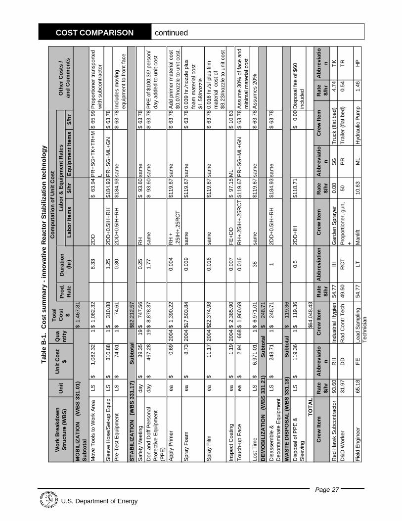
COST COMPARISON continued
Page 27
U.S. Department of Energy
Tab
le B
-1.
Co
st s
um
mar
y -
inn
ova
tive
Rea
cto
r S
tab
iliza
tion
tec
hn
olo
gy
Wo
rk B
reak
do
wn
Str
uctu
re (W
BS
)U
nit
Un
it C
ost
$Q
ua
nti
ty
To
tal
Co
st $
Co
mp
uta
tio
n o
f U
nit
Co
st
Oth
er C
ost
s /
and
Co
mm
ents
Pro
d.
Rat
eD
ura
tio
n
(hr)
Lab
or
& E
qu
ipm
ent
Rat
es
Lab
or
Item
s$/
hr
Eq
uip
men
t It
ems
$/h
r
MO
BIL
IZA
TIO
N
(W
BS
331
.01)
Su
bto
tal
$1,
467.
81
Mov
e T
ools
to W
ork
Are
aLS
$1,
082.
321
$1,
082.
328.
332D
D$
63.9
4P
R+S
G+T
K+T
R+M
L$
65.9
9P
ropo
rtio
ner t
rans
port
edw
ith s
ubco
ntra
ctor
Sle
eve
Hos
e/S
et-u
p E
quip
LS$
310.
881
$31
0.88
1.25
2DD
+0.5
IH+R
H$1
84.9
3P
R+S
G+M
L+G
N$
63.7
8
Pre
-Tes
t Equ
ipm
ent
LS$
74.6
11
$74
.61
0.30
2DD
+0.5
IH+R
H$1
84.9
3sa
me
$63
.78
Incl
udes
mov
ing
equi
pmen
t to
fron
t fac
e
ST
AB
ILIZ
AT
ION
(W
BS
331
.17)
S
ub
tota
l$6
2,21
2.57
Saf
ety
Mee
ting
day
$39
.35
19$
747.
560.
25R
H$
93.6
0sa
me
$63
.78
Don
and
Dof
f Per
sona
lP
rote
ctiv
e E
quip
men
t(P
PE
)
day
$46
7.28
19$
8,87
8.37
1.77
sam
e$
93.6
0sa
me
$63
.78
PP
E o
f $10
0.36
/ per
son/
day
adde
d to
uni
t cos
t
App
ly P
rimer
ea$
0.69
2004
$1,
390.
220.
004
RH
+.2
5IH
+.25
RC
T$1
19.6
7sa
me
$63
.78
Add
prim
er m
ater
ial c
ost
$0.0
7/no
zzle
to u
nit c
ost.
Spr
ay F
oam
ea$
8.73
2004
$17,
503.
840.
039
sam
e$1
19.6
7sa
me
$63
.78
0.03
9 hr
./noz
zle
plus
foam
mat
eria
l cos
t$1
.58/
nozz
le
Spr
ay F
ilmea
$11
.17
2004
$22,
374.
980.
016
sam
e$1
19.6
7sa
me
$63
.78
0.01
6 hr
./sf p
lus
film
mat
eria
l co
st o
f$8
.23/
nozz
le to
uni
t cos
t
Insp
ect C
oatin
gea
$1.
1920
04$
2,38
5.90
0.00
7FE
+DD
$97
.15
ML
$10
.63
Tou
ch-u
p F
ace
ea$
2.94
668
$1,
960.
690.
016
RH
+.25
IH+.
25R
CT
$119
.67
PR
+SG
+ML+
GN
$63
.78
Ass
ume
30%
of f
ace
and
min
imal
mat
eria
l cos
t
Lost
Tim
eLS
$6,
971.
011
$6,
971.
0138
sam
e$1
19.6
7sa
me
$63
.78
Ass
umes
20%
DE
MO
BIL
IZA
TIO
N
(WB
S 3
31.2
1)
S
ub
tota
l$
248.
71
Dis
asse
mbl
e &
Dec
onta
min
ate
Equ
ipm
ent
LS$
248.
711
$24
8.71
12D
D+0
.5IH
+RH
$184
.93
sam
e$
63.7
8
WA
ST
E D
ISP
OS
AL
(WB
S 3
31.1
8)
S
ub
tota
l$
119.
36
Dis
posa
l of P
PE
&S
leev
ing
LS$
119.
361
$11
9.36
0.5
2DD
+IH
$118
.71
$0.
00D
ispo
sal f
ee o
f $60
incl
uded
TO
TA
L$6
4,04
8.43
Cre
w It
emR
ate
$/h
rA
bb
revi
atio
nC
rew
Item
Rat
e$/
hr
Ab
bre
viat
ion
Cre
w It
emR
ate
$/h
rA
bb
revi
atio
nC
rew
Item
Rat
e$/
hr
Ab
bre
viat
ion
Red
Haw
k S
ubco
ntra
ctor
93.6
0R
HIn
dust
rial H
ygie
n54
.77
IHG
arde
n S
pray
er0.
08S
GT
ruck
(fla
t bed
)4.
74T
K
D&
D W
orke
r31
.97
DD
Rad
Con
tr T
ech
49.5
0R
CT
Pro
porti
oner
, gun
,+
50P
RT
raile
r (fla
t bed
)0.
54T
R
Fiel
d E
ngin
eer
65.1
8F
ELe
ad S
ampl
ing
Tec
hnic
ian
54.7
7LT
Man
lift
10.6
3M
LH
ydra
ulic
Pum
p1.
46H
P
COST COMPARISON continued
Page 28
U.S. Department of Energy
Tab
le B
-2.
Co
st s
um
mar
y -
bas
elin
e R
eact
or
Sta
bili
zati
on
tec
hn
olo
gy
Wo
rk B
reak
do
wn
Str
uctu
re (W
BS
)U
nit
Un
itC
ost $
Qu
anti
tyT
ota
l Co
st
$
Co
mp
uta
tio
n o
f U
nit
Co
st
Pro
du
cti
on
Rat
e
Du
rati
on
(h
r)
Lab
or
& E
qu
ipm
ent
Rat
esO
ther
Co
sts
/
Lab
or
Item
s$/
hr
Eq
uip
men
t It
ems
$/h
ran
d C
om
men
ts
MO
BIL
IZA
TIO
N
(W
BS
331
.01)
Su
bto
tal
$74
7.94
Mov
e T
ools
to W
ork
Are
aLS
$69
4.97
1$
694.
978.
332D
D$
63.9
4S
P+S
G+T
K+T
R+M
L$
19.4
9
Set
-up/
War
m-u
pE
quip
men
tLS
$52
.97
1$
52.9
70.
52D
D+0
.5R
CT
$88
.67
SP
+SG
+ML+
GN
$17
.28
Incl
udes
mov
ing
equi
pmen
t to
the
fron
t fa
ce
ST
AB
ILIZ
AT
ION
(W
BS
331
.17)
S
ub
tota
l$
19,9
52.7
1
Saf
ety
Mee
ting
day
$20
.31
16$
324.
880.
252D
D$
63.9
4sa
me
$17
.28
Don
and
Dof
fP
erso
nal P
rote
ctiv
eE
quip
men
t (P
PE
)
day
$33
2.48
16$
5,31
9.67
1.77
2DD
$63
.94
sam
e$
17.2
8P
PE
of $
94.3
6/pe
rson
/day
adde
d to
uni
t cos
t
Pre
-Ins
pect
ion
ea$
1.03
2004
$2,
062.
930.
011
2DD
+0.2
5R
CT
$76
.30
sam
e$
17.2
8
App
ly P
rimer
ea$
0.65
2004
$1,
298.
950.
0034
sam
e$
76.3
0sa
me
$17
.28
Add
prim
er m
ater
ial c
ost
$0.3
3/no
zzle
to u
nit c
ost
Spr
ay F
ilmsf
$2.
1520
04$
4,30
3.61
0.00
9sa
me
$76
.30
sam
e$
17.2
8A
dd p
aint
mat
eria
l cos
t$1
.28/
nozz
le to
uni
t cos
tPo
st-I
nspe
ctio
nea
$1.
2620
04$
2,52
2.49
0.01
1FE
+DD
$97
.15
sam
e$
17.2
8
Tou
ch-u
pea
$0.
8413
36$
1,12
5.24
0.00
92D
D+0
.25
RC
T$
76.3
0sa
me
$17
.28
60%
repa
inte
d an
d m
inim
alm
ater
ial c
ost
Lost
Tim
els
$2,9
94.6
41
$2,
994.
6432
sam
e$
76.3
0sa
me
$17
.28
Ass
umed
to b
e 20
%
DE
MO
BIL
IZA
TIO
N
(WB
S 3
31.2
1)
S
ub
tota
l$
52.9
7
Dis
asse
mbl
e &
Dec
onta
min
ate
Equ
ipm
ent
LS$
52.9
71
$52
.97
0.5
2DD
+0.5
RC
T$
88.6
7sa
me
$17
.28
WA
STE
DIS
PO
SA
L (W
BS
331
.18)
S
ub
tota
l$
116.
70
Dis
posa
l of P
PE
and
Pla
stic
S
leev
ing
LS$
116.
701
$11
6.70
0.5
2DD
+1R
CT
$11
3.39
$0.
00D
ispo
sal f
ee o
f $60
incl
uded
TO
TA
L$
20,8
70.3
2
Cre
w It
emR
ate
$/h
rA
bb
revi
ati
on
Cre
w It
emR
ate
$/h
rA
bb
rev
iati
on
Cre
w It
emR
ate
$/h
rA
bb
revi
atio
nC
rew
Item
Rat
e $/
hr
Ab
bre
viat
io
n
Indu
stria
l Hyg
ieni
st54
.77
IHR
ed H
awk
Sub
cont
ract
or93
.60
RH
Pro
porti
oner
,G
un, H
ose
50P
RA
ir C
ompr
esso
r6.
74A
C
Fie
ld S
uper
viso
r59
.60
SU
Rig
ger
43.5
7R
GT
ruck
Tra
ctor
11.7
1T
TT
ruck
(fla
t bed
)4.
74T
K
D&
D W
orke
r31
.97
DD
Fiel
d E
ngin
eer
65.1
8F
EG
ener
ator
3.07
GN
Tra
iler (
flat b
ed)
0.54
TR
Tea
mst
er36
.35
TM
Lead
Sam
plin
gT
echn
icia
n54
.77
LTS
pray
Pum
p3.
50S
PM
anlif
t10
.63
ML
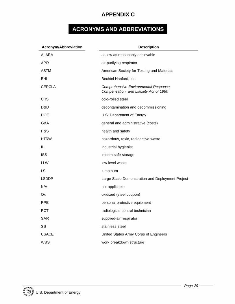
Page 29
U.S. Department of Energy
APPENDIX C
ACRONYMS AND ABBREVIATIONS
Acronym/Abbreviation Description
ALARA as low as reasonably achievable
APR air-purifying respirator
ASTM American Society for Testing and Materials
BHI Bechtel Hanford, Inc.
CERCLA Comprehensive Environmental Response,Compensation, and Liability Act of 1980
CRS cold-rolled steel
D&D decontamination and decommissioning
DOE U.S. Department of Energy
G&A general and administrative (costs)
H&S health and safety
HTRW hazardous, toxic, radioactive waste
IH industrial hygienist
ISS interim safe storage
LLW low-level waste
LS lump sum
LSDDP Large Scale Demonstration and Deployment Project
N/A not applicable
Ox oxidized (steel coupon)
PPE personal protective equipment
RCT radiological control technician
SAR supplied-air respirator
SS stainless steel
USACE United States Army Corps of Engineers
WBS work breakdown structure