Embed Size (px)
Citation preview
G. Eiget'lberger H. Schuler
FEDERAL REPUBLIC OF GERMANY
Reactor stability and safe reaction engineering Stable operation of a chemical reactor and stability (in the stability-theory sense) of a chemical process are not necessarily synonymous concepts. Thus, appropriate control can permit reliable operation at an unstable operating point, while even global stability does not necessarily rule out a runaway reaction, e.g., when a strongly exothermic reaction has a pronounced parametric sensitivity. The concepts of stability and parametric sensitivity are explained in relation to strongly exothermic reactions in stirred-tank and tubular reactors. The conventional view of reaction engineering and the theory of thermal explosions, commonly used in safety engineering, are considered in detail. Practical problems of safe reaction engineering are discussed in relationship to the control of batch and semibatch reactors and to the behavior of tube-bundle reactors.
1. Introduction
Problems of reactor stability and safe reaction engineering have in the past been considered either as problems in chemical reaction engineering or as problems in safety engineering with entirely different methods being used in the two cases. In reaction engineering, the emphasis is on research into the stability of chemical processes, in which the problem of mathematical stability is preeminent, but which is restricted to relatively simple, idealized models of reactors. Safety engineering, on the other hand, concentrates on the experimental determination of
From Chemie-Ingenieur-Technik 58, No .. 8, pp. 655-665 (1986), with permission of Verlag Chemie, Weinheim/Bergstr. Professor Dr.-Ing. Gerhart Eigenberger is Head of the Institut (Laboratory) {'dr Chemische Verfahrenstechnik Universitiit Stuttgart, Boblingerstr. 72, 7000 Stuttgart 1; Dr.lng. Hans Schuler is associated with BASF AG, Technische Entwicklung/lnformatik, 6700 Ludwigshafen/Rh.
0020-0318/89/2916-0012/$05.00 c 1989, American Institute of Chemical Engineers.
specific, characteristic data impinging on safety, in which the evaluation and interpretation of the relevant data are based almost exclusively on the theory of thermal explosions.
From the practical standpoint of safe reaction engineering, neither procedure is entirely satisfactory. Except for an at times very theoretical and abstract exposition, research on reaction engineering has only limited practical significance for reactor stability, since, in practice, stability and safe reaction engineering are not necessarily synonymous. Thus, a reactor can, ,with suitable control, be operated safely at an unstable operating point, w.hile even global stability does not, necessarily rule out a runaway reaction. Such is the case when a strongly exothermic reaction has a pronounced parametric sensitivity, and a variation in the operating conditions increases markedly the liberation of the heat of reaction.
On the other hand, the basis for evaluating and interpreting safety-engineering data is the strongly idealizing theory of thermal explosions, and'it is difficult to answer fully the questions of safe reaction engineering using these data.
12 January J989 Vol. 29, No.1 INTERNATIONAL CHEMICAL ENGINEERING

In this paper, the concepts of stability and parametric sensitivity are explained in relationship to ideal, stirred-tank and tubular reactors with strongly exothermic reaction, followed by a summary of Semonov's theory of thermal explosions as a special case for zero-order batch reactions. Some practical problems of safe reaction engineering in batch, semibatch, and bundled-tube reactors are then dealt with, viz., the uncontrolled liberation of the heat of reaction with limited removal of heat. The purpose of presenting the problems of reaction engineering and safety engineering together is to plead the case for a greater joint mastery of the two subjects, and the recognition that they are mutually complementary.
2. Basic theory
the better known of which is that based on the heat ~eneration curve QE and the heat removal line QA in Figure 1a. This solution follows from the steady-state energy balance, in which the concentration in the rate of reaction is replaced by Equation (1):
~qpcp+UA)(1S-Tc), =::: V(-MlR)r(Cs(Ts),Ts) .. (3) v w
QA QE
where the subscript S refers to the steady state. The graph in Figure 1b, which follows on from
the linear relationship TG (transport line) and the nonlinear relationship RK (the reaction curve) between the steady-state temperature and concentration, is more appropriate for the ensuing discussion, since it leads directly to the phase plane representing the dynamic behavior:
The foundations of the theory of thermal V(-MlR
)r(Cs'1S)= q(-MlR)(CO-CS
) = (qpcp+UA)(Ts-Tc) stability were evolved, to a large extent, independ- ... .. >v .. ently for chemical reactions and chemical iK TG (4) reactors. The subject of safety engineering still depends substantially on the theory of thermal explosions [1-3], while reaction engineering is chiefly concerned with the question of reactor stability.
2.1. Continuous, stirred-tank reactor with an exothermic reaction
An ideal, continuous, stirred-tank reactor with a simple, exothermic reaction is the best known and most fully investigated example used to study reactor stability. Its model is as follows.
Mass balance for the concentration C of a key component:
(1)
Energy balance for equal feed temperature To and cooling temperature Tc:
dT V pCpdi= (qpc
P + UA)(Tc-T) + V(-MlR)r(C, T) (2)
The principal features of the steady-state and dynamic behavior of this model are now discussed.
2.1.1. Steady 8tate
Since the time differentials in Equations (1) and (2) are zero in the s~ady state, the steady-state temperature and concentration are obtained by solving two nonlinear equations. The solution is usually illustrated graphically in one of two ways,
With Figure 1, it is simple to discuss the manner in which the steady-state temperature and concentration vary with changes in the operating parameters. Figure 2 shows this behavior for the cooling temperature. Two basic patterns can be differentiated, depending on the slope of the transport line, viz., a single-valued solution (Figure 2a) or, within a certain range of values of the parameter, three steady-state solutions (Figure 2b).
In the former case, the parametric sensitivity is high, if a small change in an operating parameter (~Tc) produces a large shift in the steady state (~Ts). However, the system is always stable, in the sense that, if the change in the parameter is small enough, the change in the steady state is also small (see Figure 2c).
~---<>--I----Ts Tc Ts
Cs
bl
L---it-.--i-\-::::::::::::""""'-_ Ts Tc Ts
Fig. 1. a) Heat generation curve QE and heat removal line Q A of a continuous, stirred-tank reactor. The intersection of the two lines determines the steady-state temperature 78. b) Transport line TG and reaction curve RK. This graph also gives the steady-state concentration Cs and an interpretation of the steady-state points on the phase diagram.
INTERNATIONAL CHEMICAL ENGINEERING Vol. 29, No. I January 1989 13
Cs Te 0) Cs Te b)
Co
Cs
Ts Ts Ts
Tc e) /
/ Tc
liTe
auenc~ing
llTs Ts L---+-~--4---Ts
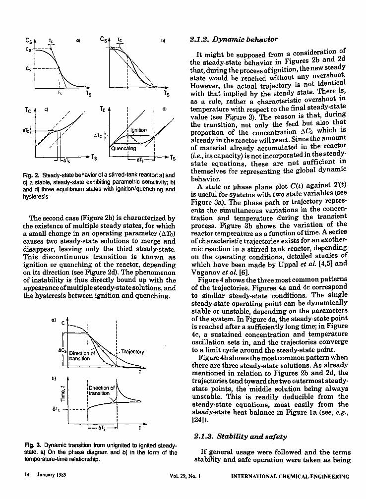
Fig. 2. Steady-state behavior of a stirred-tank reactor: a) and c) a stable. steady-state exhibiting parametric sensitivity; b) and d) three equilibrium states with ignition/quenching and hysteresis.
The second case (Figure 2b) is characterized by the existence of multiple steady states, for which a small change in an operating parameter (aTe) causes two steady-state solutions to merge and disappear, leaving only the third steady-state. This discontinuous transition is known as ignition or quenching of the reactor, depending on its direction (see Figure 2d). The phenomenon of instability is thus directly bound up with the appearance of multiple steady-state solutions, and the hysteresis between ignition and quenching.
0) C
b)
-......
I
\ Direction of \ transition I I I
I I I I I I I I I
~~ Trajectory
T
T
Fig. 3. Dynamic transition from unignited to ignited steadystate. a) On the phase diagram and b) in the form of the temperature-time relationship.
2.1.2. Dynamic behavior
'd ti n of It might be supposed from a conSI era 0
the steady-state behavior in Figures 2b and 2d that, during the process ofignition, the new steady state would be reached without. any o~ersh?o\ However, the actual trajectory IS not Identic.a with that implied by the steady state. There ~s, as a rule, rather a characteristic overshoot III temperature with respect to the final steady-st~te value (see Figure 3). The reason is that, dunng the transition, not only the feed but als~ th~t proportion of the concentration aCs WhICh IS already in the reactor will react. Since the amount of material already accumulated in the reactor (i.e., its capacity) is not incorporated in t~e.stead!state equations, these are not suffICient I.n themselves for representing the global dynamIC behavior.
A state or phase plane plot C(t) against T(t) is useful for systems with two state variables (see Figure 3a). The phase path or trajectory represents the simultaneous variations in the concentration and temperature during the transient process. Figure 3b shows the variation of the reactor temperature as a function of time. A series of characteristic trajectories exists for an exothermic reaction in a stirred tank reactor, depending on the operating conditions, detailed studies of which have been made by Uppal et al. [4,5] and Vaganov et al. [6].
Figure 4 shows the three most common patterns of the trajectories. Figures 4a and 4c correspond to similar steady-state conditions. The single steady-state operating point can be dynamically stable or unstable, depending on the parameters of the system. In Figure 4a, the steady-state point is reached after a sufficiently long time; in Figure 4c, a sustained concentration and temperature oscillation sets in, and the trajectories converge to a limit cycle around the steady-state point.
Figure 4b shows the most common pattern when there are three steady-state solutions. As already mentioned in relation to Figures 2b and 2d, the trajectories tend toward the two outermost steadystate points, the I middle solution being always unstable. This is readily deducible from the steady-state equations, most easily from the steady-state heat balance in Figure 1a (see, e.g., [24]).
2.1.3. Stability and safety
If general usage were followed and the terms stability and safe operation were taken as being
14 January 1989 Vol. 29, No. I INTERNATIONAL CHEMICAL ENGINEERING
C a) C -" \ b)
~\ ~,
----- =-. Tcrit T T crit T
c)
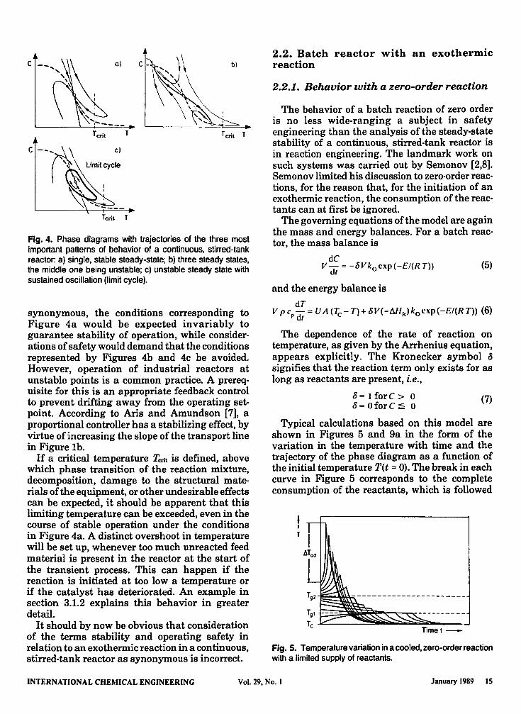
Fig. 4. Phase diagrams with trajectories of the three most important patterns of behavior of a continuous. stirred-tank reactor. a) single. stable steady-state; b) three steady states. the middle one being unstable; c) unstable steady state with sustained oscillation (limit cycle).
synonymous, the conditions corresponding to Figure 4a would be expected invariably to guarantee stability of operation, while considerations of safety would demand that the conditions represented by Figures 4b and 4c be avoided. However, operation of industrial reactors at unstable points is a common practice. A prerequisite for this is an appropriate feedback control to prevent drifting away from the operating setpoint. According to Aris and Amundson [7], a proportional controller has a stabilizing effect, by virtue of increasing the slope of the transport line in Figure lb.
If a critical temperature Tcrit is defined, above which phase transition of the reaction mixture, decomposition, damage to the structural materials of the equipment, or other undesirable effects can be expected, it should be apparent that this limiting temperature can be exceeded, even in the course of stable operation under the conditions in Figure 4a. A distinct overshoot in temperature will be set up, whenever too much unreacted feed material is present in the reactor at the start of the transient process. This can happen if the reaction is initiated at too low a temperature or if the catalyst has deteriorated. An example in section 3.1.2 explains this behavior in greater detail.
It should by now be obvious that consideration of the terms stability and operating safety in relation to an exothermic reaction in a continuous, stirred-tank reactor as synonymous is incorrect.
2.2. Batch reactor with an exothermic reaction
2.2.1. Behavior with a zero-order reaction
The behavior of a batch reaction of zero order is no less wide-ranging a subject in safety engineering than the analysis of the steady-state stability of a continuous, stirred-tank reactor is in reaction engineering. The landmark work on such systems was carried out by Semonov [2,8]. Semonov limited his discussion to zero·order reactions, for the reason that, for the initiation of an exothermic reaction, the consumption of the reactants can at first be ignored.
The governing equations of the model are again the mass and energy balances. For a batch reactor, the mass balance is
dC V- = -oVk cxp(-E/(RT»
dt 0 (5)
and the energy balance is
dT V P cp dr = V A (Tc - T)+ oV(-MlR)kocxp(-EI(RT» (6)
The dependence of the rate of reaction on temperature, as given by the Arrhenius equation, appears explicitly. The Kronecker symbol a signifies that the reaction term only exists for as long as reactants are present, i.e.,
0= 1 forC > 0 0= oforC:;;; 0
(7)
Typical calculations based on this model are shown in Figures 5 and 9a in the form of the variation in the temperature with time and the trajectory of the phase diagram as a function of the initial temperature T(t = 0). The break in each curve in Figure 5 corresponds to the complete consumption of the reactants, which is followed
t I T
Timet-
Fig. 5. Temperature variation in a cooled. zero-order reaction with a limited supply of reactants.
INTERNATIONAL CHEMICAL ENGINEERING Vol. 29. No. I January 1989 15

by cooling to the temperature Tc. With a sufficiently high initial temperature the reaction proceeds so rapidly that the heat 'emitted to the surroundings dUring the reaction phase is negligible in compatison with the heat which is generated. The rise in temperature due to the reaction approaches the adiabatic value
(8)
There is thus a continuous succession of transitions, depending on the initial temperature. The final steady state is invariably characterized by the conditions T ~ Tc and C = O. There are no multiple steady states with ignition and quenching limits; a batch reactor always has a unique and stable mode of operation. This is true of any batch or semibatch reactor with any order of or combination of reactions.
2.2.2. Theory of thermal explosion
Figures 5 and 9a are characterized by the existence of two distinct initial temperatures Tgl and Tg2, which delimit the regions in which the temperature initially rises or falls. If T = Tgl or Tg2, the temperature remains constant for as long as any feed unconsumed remains. A temporary state of equilibrium is present during this time, in which the heat generated by the reaction equals the heat emitted to the cooler surroundings
UA(~-~,) = V8(-MlR)kocxp(-EI(R~»
~---------~v----------Q A ("')
(9)
These potential equilibrium temperatures Tg can be determined graphically in Figure 7. In addition to these two points, there is another point of intersection in a very h~gh and physically'meaningless range of temperature.
The limiting nature of Tg2 is better delineated in a reaction in which the adiabatic temperature rise is much greater (see Figure 6). This is the basis of Semonov's theory of thermal explosions. This theory provides analytical criteria for differentiating quasiadiabatic and quasiisothermal patterns of behavior in a process. Figure 7 shows that there is a critical cooling or ambient temperature Tt;, above which a temporary state of equilibrium in the meaningful range of temperatures cannot occur. The conditions for T~ are
(10)
It follows from Equation (9) that
T
---------~1 ~~;;~~==:;~===-----~ ~ ~~--~----------=-----~
Timet -
Fig. 6. Temperature variation in a cooled, zero~order r~acti~n with a large supply of reactants (very hIgh adIabatIC temperature rise).
{ E V (-M/ R) ko cxp (-EI(R T~» } = 0 (11)
In R T! A U z
This equation is a standard formula for evaluating data on the therI1lal stability of a substance in safety engineering. Figure 8a enables chara~teristic experimental data, expressed as the ratio VI A to be determined as a function of the selfignition temperature Tz. The slope of Figure 8?gives the energy of activation EI R. For expenmental values of VI(AT~) in the region above the plotted line, the temperature increases until.all the reactants are consumed. This is the region in which there is no point of intersection between QA and QE.
Another way of determining the safetyengineering data of decomposition reactions using so-called adiabatic storage tests derives from the adiabatic energy balance, viz., Equation (6) with UA = O. When ~ = 1, i.e., for unlimited supplies of the reactants, and under certain simplifying assumptions regarding the exponential dependence of the rate of reaction on temperature, an analytical solution for the adiabatic induction time Atad is obtained, i.e., the period of time after which infinitely high (calculated) temperatures are attained (see Figure 6):
Fig. 7. Semonov diagram of an exothermic, zero-order reaction.
16 January 1989 Vol. 29, No. I INTERNATIONAL CHEMICAL ENGINEERING

0) b)
Fig. 8. Diagrams for evaluating safety-engineering data: a) dependence of self-ignition temperature Tz on the experimental value VIA; b) adiabatic induction time ~tad as a function of the initial temperature To.
R Tb 1 ~t.d= E ~T E (12)
.d ko cxp { - R T. } o
This formula allows the adiabatic induction time to be estimated from the initial temperature To, according to Figure 8b (see also [9,10]).
If the initial temperature is below Tg2, the temperature of the reactor approaches Tgl asymptotically, as long as reactive material remains unconsumed. If the initial temperature is above Tg2, the temperature of the reactor continues to increase exponentially until all the reactive material is consumed. Tgl is therefore frequently characterized as being stable and Tg2 as being unstable, but this is somewhat misleading, since there is no problem of stability in the strict sense, with multiple steady states and hysteresis between ignition and quenching, as exists with a continuous, stirred-tank reactor. However, reactions with a very large adiabatic rise in temperature have such a high parametric sensitivity that Tg2 has the character of a limiting temperature, above which the reaction runs out of control (see Figure 6).
2.2.8. Positive-order reaction-parametric sensitivity
If the conversion is very low, almost every reaction can be approximated as zero-order. This assumption is the basis of the foregoing discussion of the determination of the characteristic safety-engineering data. However, when the conversion is high, variations in the concentration play a role. This is the field of study of reaction engineering. The behavior of reactions of n-th order is usually studied in terms of the steady-state behavior of a tubular reactor. It should be obvious that an ideal, steady-state, tubular reactor can be modeled by means of the equations for a batch reactor, if the time t is replaced by the residence time z/v.
u c
~ C G> CJ C o o
u c o
1 G> CJ C o o
0)
T 9 2 Temperature T -
Tc Temperature T-
Fig. 9. Phase diagrams with trajectories of exothermic batch reactions: a) zero-order reaction; b) first-order reaction.
Figure 9b shows the phase plane and Figure 10 the temperature-time relationship as a function of the cooling intensity N, given by Equation (14), for a first-order, exothermic reaction. There is a single steady state at T = Tc and C = 0, just as with a zero-order reaction.
Regions of pronounced parametric sensitivity with respect to the initial temperature (Figure 9b) and the cooling intensity (Figure 10) are easily recognizable. This problem of parametric sensitivity has been thoroughly investigated using the example of a tubular reactor. Barkelew [11] was the first to use it for differentiating between sensitive and insensitive operating ranges, starting from the mass and energy balances for a batch reactor, viz., Equations (5) and (6), with a reaction of n-th order, i.e., with 6(C) replaced
Timet -
Fig. 10. Parametric sensitivity of the temperature-time relationship of a batch reaction as a function of the cooling intensity.
INTERNATIONAL CHEMICAL ENGINEERING Vol. 29, No.1 January 1989 17
by a dependence on concentration proportional to CD. The maximum rise in temperature for the reaction
llTm .. = Tm .. - Tc or Xmax = E (Tmax - Tc)/(R TV (13)
can be expressed as functions of the dimensionless reacting strength S and the cooling intensity N (see Figures 11a and 11b)
VA N=---------
E pCpVkoexp{ - -} co-t
R Tc (14)
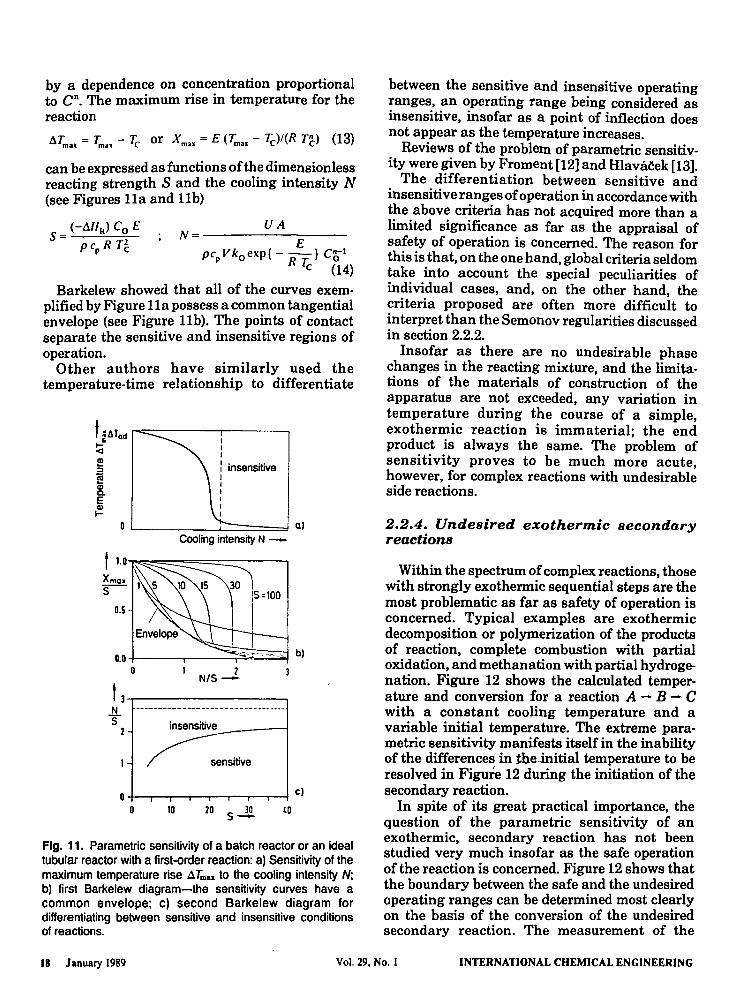
Barkelew showed that all of the curves exemplified by Figure 11a possess a common tangential envelope (see Figure 11b). The points of contact separate the sensitive and insensitive regions of operation.
Other authors have similarly used the temperature-time relationship to differentiate
t ~ATad 1"""::::=----'1------. ~ : !!! : insensitive ~ I
8. : E ~
L. ____ ..i...:=====d 01 Cooling intensity N -
1.0~~=:::====:::::----,
Xmax _s-
0.5
+-__ -. __ -.~~~ bl
1 2 N/S-
t 3..------------, N 5
2 insensitive~ __ ---.
o +--.-""'---'r--"'-~---r--r--l c I o 10 20 s-1! to
Fig. 11. Parametric sensitivity of a batch reactor or an ideal tubular reactor with a first-order reaction: a} Sensitivity of the maximum temperature rise llTmu to the cooling intensity N: b) first Barkelew diagram-the sensitivity curves have a common envelope: c) second Barkelew diagram for differentiating between sensitive and insensitive conditions of reactions.
between the sensitive and insensitive operating ranges, an operating range being considered as insensitive, insofar as a point of inflection does not appear as the temperature increases.
Reviews of the problem of parametric sensitivity were given by Froment [12] and Hlava~ek [13].
The differentiation between sensitive and insensitive ranges of operation in accordance with the above criteria has not acquired more than a limited significance as far as the appraisal of safety of operation is concerned. The reason for this is that, on the one hand, global criteria seldom take into account the special peculiarities of individual cases, and, on the other hand, the criteria proposed are often more difficult to interpret than the Semonov regularities discussed in section 2.2.2.
Insofar as there are no undesirable phase changes in the reacting mixture, and the limitations of the materials of construction of the apparatus are not exceeded, any variation in temperature during the course of a simple, exothermic reaction is immaterial; the end product is always the same. The problem of sensitivity proves to be much more acute, however, for complex reactions with undesirable side reactions.
2.2.4. Undesired exothermic secondary reactions
Within the spectrum of complex reactions, those with strongly exothermic sequential steps are the most problematic as far as safety of operation is concerned. Typical examples are exothermic decomposition or polymerization of the products of reaction, complete combustion with partial oxidation, and methanation with partial hydrogenation. Figure 12 shows the calculated temperature and conversion for a reaction A - B - C with a constant cooling temperature and a variable initial temperature. The extreme parametric sensitivity manifests itself in the inability of the differences in the-initial temperature to be resolved in Figure 12 during the initiation of the secondary reaction.
In spite of its great practical importance, the question of the parametric sensitivity of an exothermic, secondary reaction has not been studied very much insofar as the safe operation of the reaction is concerned. Figure 12 shows that the boundary between the safe and the undesired operating ranges can be determined most clearly on the basis of the conversion of the undesired secondary reaction. The measurement of the
18 January 1989 Vol. 29. No. I INTERNATIONAL CHEMICAL ENGINEERING

1 c:
oQ !!! (I)
f: 8 ~~------------------~ ucr---------------~~==~
t CII c: o
0i!!
~ c: o U Timet -
Fig. 12. Synthesis reaction rl with a strongly exothermic, consecutive reaction r2: A ~ B!.! C.
concentration of a key component in the secondary reaction is therefore a sensible and reliable way of differentiating between safe and undesirable modes of operation. This was considered by, inter alia, Westerterp and Overtoom [14]. Should control of the reaction be impossible in this way, indirect methods are necessary. One model-based method of analysis of the initiation of an undesired side reaction is presented in [15], while [16] is concerned with experimental investigations based on such methods.
To recapitulate, in contrast to a continuous, stirred-tank reactor, a batch reactor always has a stable and unique mode of operation, but parametric sensitivity is likely to be prejudicial to safe operation, especially with strongly exothermic secondary reactions. From the pragmatic viewpoint of the plant manager, it is irrelevant whether or not it is instability or extreme parametric sensitivity which is responsible for a runaway.
2.3. Tubular reactors
The correspondence between the model of a batch reactor and the steady-state model of an ideal tubular reactor has already been mentioned. This system lacks a feedback for the appearance of instability with multiple steady states, which in a continuous, stirred-tank reactor is brought about by the complete mixing of the contents of the reactor with the feed. However, actual reactors do have such feedback to a not inconsiderable
degree. In the present case, for which thermal instability is the concern, the question is one of thermal feedback.
A considerable amount of work in the field of reaction engineering has been done on the problem of stability in tubular reactors. Among the causes of thermal feedback which have been suggested are the backward conduction of heat in the reaction mixture or in the wall of the reactor tube, thermal feedback in a countercurrent cooling medium or the feed ("autothermal reaction"), and heat exchange between the feed and the outflow. In this way, not only are multiple steady states with hysteresis between ignition and quenching possible, but under certain conditions, continuous oscillations, comparable with the limit-cycle oscillations characteristic of continuous, stirredtank reactors, can also appear. A more detailed discussion of the stability of tubular reactors is to be found in [17-19].
3. Practical problems of safe reactionengineering
3.1. Stirred-tank reactors
It has already been pointed out that, with proper stabilizing control, a continuous, stirred-tank reactor can be operated safely at an unstable operating point, provided there is a direct-acting manipulated variable. It is normal practice for the temperature inside the reactor to be controlled through the cooling temperature as the manipulated variable [25]. Discontinuous operation of a batch or semibatch reactor is more difficult than continuous operation, since no steady state can exist under these conditions.
8.1.1. Batch reactors under feedback control
The temperature inside an industrial-scale, batch reactor is normally controlled by means of the cooling temperature. Figure 13 illustrates the typical temperature variations during a simple exothermic reaction. In this example, the temperature of the cooling j acket ranges from 10 °C(river water) to 80 °C. If the desired temperature is 65°C, the reaction mixture must first be heated, i.e., the temperature of the cooling jacket is at its maximum value. Although control through the cooling temperature is always quick-acting, unavoidable lags in the control system produce a damped oscillation around the temperature setpoint once the reaction starts.
INTERNATIONAL CHEMICAL ENGINEERING Vol. 29. No.1 January 1989 19

90r-----------------______ ___
l ao 70
~60 "'50 Q)
:; 40 ~ 30 8. E 20 Q)
... 10
T
o~----------------------~ Time t-
Fig. 13. Batch reactor with manipulated cooling temperature. Reaction initiated by heating reaction mixture to the desired temperature rSoD •
90r-----------------------~
ao.r------70
060 o ;:50 !!! 40 ::l
~ 30 8. 20 E
T
~ 10 0~ ________________ ~3~ __ ~
Timet-
Fig. 14. Batch reactor with manipulated cooling temperature as in Figure 13, but with more stringent reaction conditions. In case 3, the desired temperature can no longer be held constant (cooling temperature r., at its lower limit).
Slightly more severe reaction conditions (higher initial concentration or temperature and/or poorer heat transfer to the cooling medium) produce the transient behavior shown in Figure 14. In case 2, the cooling temperature temporarily falls to its lower limit, but the cooling effect is still sufficient to control the reaction. This is not· so in case 3, where the cooling temperature remains at its lower limit, but the desired temperature cannot be maintained. The reaction begins to run away and emergency measures are needed to bring it under control.
The large amounts of unreacted material which are present at the start of the reaction in an ideal batch reactor always pose a latent risk, if the reaction is strongly exothermic. For this reason, such reactions are not carried out in batch, stirredtank reactors, but in fed-batch reactors.
3.1.2. Semibatch reactors
In the semibatch or fed-batch mode of operation, only a fraction of the reacting mixture is present
initially, the rest being added gradually in the so-called dosage phase. The advantage ~f such a procedure is that the feed rate .proV1d~s an additional manipulated variable WIth whlch to control the rate of liberation of heat.
With many reactions, some of the reactants are already present and the others are added s~owl~. This mode of operation was recently studled m detail by Hugo and Steinbach [20-22], w~o showed that this means strongly exothermlc reactions always enter the critical region, if the fed component does not react immediately, but accumulates in the reactor. Causes of such accumulation are, besides a too rapid dosage, a temperature of reaction that is too low, or a deactivation of the catalyst, or some other factor which delays the initiation of the reaction.
Hugo and Steinbach showed that there is a very simple strategy for this kind of ~emibatch operation, which enables safe, largely lsothermal conditions to be achieved, by relinquishing control over the temperature inside the reactor. This is illustrated in Figures 15 and 16 for an exothermic reaction with the overall formula A + B - products. All of the component A is present at the start of the reaction and is heated up to the constant temperature Tc of the cooling jacket. The component B is added at a constant
21
:J _1 ~ Cooling tempe~ature . - _ ... ------------------------- ..
-:;l0 I I I ' -2 -~ ----
&!. 0 025 0.5 0.75 1 1.25 1.5 175 2 .---- Dosage --t" After-reaction -
1 I I ---,
Reaction r~te dNA/dt I aet 'ai" ~ :OB Z C 0.6
~ l!? O.L
C 02 ::l
,
o E «
OL-------~---~~ o 0.25 0.5 0.15 1 125 15 175 2
Time (normalized) -
Rg. 15. Semibatch reactor with exothermic reaction and constant cooling temperature. Variations of temperature and concentration of reactant of A (already present) + 8 (dosed). Accumulation of the reactant 8 leads to a temporary runaway of the temperature.
20 January 1989 VoL 29. No. I INTERNATIONAL CHEMICAL ENGINEERING

i l-rl-------.-----.!:d ~ i I 01 . .s oj
!!? I
~ 1
~ -11 ~~~~~~~~~r~r~-----""--"'---,S! I :
~ ~2 .:. ~ 0 0.25 0.5 0.75 1 1.25 1.5 175 2 a: ..---- Dosage ---,-- After-reactlon-.
l' -l' ~,
~ 10.8
Z I ~ 0.6 I ~ !!? QL Reaction rate dN,./dl
E ::)
o E <
--<. i I . 2Ns 1\,"
oL~~~~;===:~ o 025 0.5 0.75 1 1.25 1.5 175 2
Time (normalized) -
Fig. 16. Semibatch reactor with exothermic reaction: controlled reaction of the dosed component by suitable choice of cooling temperature and dosage-rate after Hugo and Steinbach [21,22).
volumetric rate of flow from the time t = 0 until the end of the dosage-time t = 1.
Under unfavorable operating conditions, e.g., a too low temperature Tc of the cooling jacket or a too high rate of dosage of the component B, the latter accumulates in the reactor before the reaction is initiated by the self-heating effect. The result is a large overshoot in the temperature of the reactor (see Figure 15).
If the operating conditions are set correctly (high enough temperature of the cooling jacket, slow enough rate offeed), an equilibrium between the feed and consumption of the component B is quickly reached; the concentration of B remains at a low and approximately time-invariant level, and the component A is present in large excess until the end of the dosage-time. Hence, the rate of reaction and thus the heat generated also remain more or less constant during the dosagetime. This explains the near invariance of the temperature of the reactor while the second component is being added, even though the temperature inside the reactor is not being controlled (see Figure 16).
In a number of cases, one reactant cannot be present in full quantity at the beginning of the reaction on reaction-engineering reasons. This is the case with those polymerization reactions in which a monomer and an initiator have to be added in a constant ratio. A normal strategy for
a) Normal operation
Feed
g I Production rate g Q)
a:
~ UD..--------,
=-\00
~ 1001 '0100 III !!? 100 '0 100
§ 0 00 +'--~-r_.,._,__.___._.."..,--' ~ 0
< I ! Time, hr
b) Deactivation of initiator
I ! Time, hr
Fig. 17. Semibatch reactor with simultaneous dosage of both reactants: a) normal operation; b) temporary deactivation of the catalyst leading to accumulation of reactants and overshoot of the temperature of reaction.
such cases is shown in Figure 17a. As with a pure batch reactor (see section 3.1.1.), the temperature inside the reactor is controlled, with, in this case, the temperature of the cooling jacket lying in the range of - 15 - 95 ac. Approximately 10% of the reactants are present initially. Mter the reaction has been initiated in a similar way to that for an ideal batch reactor, the rest of the reactants are added at a constant rate. Under normal operating conditions, equilibrium is established between feed and consumption during the dosage phase, so that the amount of unreacted feed present in the reactor (the amount of reactants) remains at a low, almost constant level.
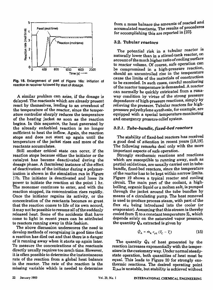
There are two critical phases in such a mode of operation. The first is the point of time after the initiation of the reaction, at which the continuous dosage of the reactants is started. This phase is shown in Figure 18, which is an enlargement of part of Figure 17a. If the dosage is started too soon, the inmixing of the cold inflow quenches the still feeble reaction. The reactants which are being added in a continuous stream are unable to react and begin to collect in the reactor. Once the reaction eventually comes to life, the accumulated reactants produce an uncontrolled overshoot of the temperature.
INTERNATIONAL CHEMICAL ENGINEERING Vol. 29, No. I January 1989 21
5,----------------------, _ I Feed (molltime) ~ I., /' ' ~ ~ '0 .s3 ! c: 2 o
~ £ 1
~ ,--~-----------------I. ,'\ : \ I Reaction (mol/time) , ' , I ,
J I ,
" °O~~~I.~OO--L-8~OO~--1-2~OO----1~~--~2~
Time (5)-
Fig. 18. Enlargement of part of Figure 16a: initiation of reaction in receiver followed by start of dosage.
A similar problem can arise, if the dosage is delayed. The reactants which are already present react by themselves, leading to an overshoot of the temperature of the reactor, since the temperature controller sharply reduces the temperature of the heating jacket as soon as the reaction begins. In this sequence, the heat generated by the already enfeebled reaction is no longer sufficient to heat the inflow. Again, the reaction stops and does not start up again until the temperature of the jacket rises and more of the reactants accumulates.
Still another critical state can occur, if the reaction stops because either the initiator or the catalyst has become deactivated during the dosage phase. A (harmless) instance of the effect of deactivation of the initiator during a polymerization is shown in the simulation run in Figure 17b. The initiator is deactivated and loses its power to initiate the reaction at the point 1 hr. The monomer continues to enter, and with the reaction stopped, its concentration rises rapidly. Once the initiator regains its activity, or the concentration of the reactants becomes so great, that the reaction comes to life of its own accord, it may not be possible to resume all of the suddenly released heat. Some of the accidents that have come to light in recent years can be attributed to reactors running away in this fashion.
The above discussion underscores the need to develop methods of recognizing in good time that a reaction has died out and that there is a danger of it running away when it starts up again later. To measure the concentrations of the reactants directly usually requires too much time. However, it is often possible to determine the instantaneous rate of the reaction from a global heat balance in the reactor. The rate of the reaction is the missing variable which is needed to determine
from a mass balance the amounts of reacted and accumulated reactants. The results of procedures for accomplishing this are reported in [23].
3.2. Tubular reactors
The potential risk in a tubular reactor is naturally lower than in a stirred-tank reactor, on account of the much higher ratio of cooling .surface to reactor volume. Of course, safe operatIOn ~an be compromised in a high-pressure reactIon, should an uncontrolled rise in the temperat~re cause the limits of the materials of constructIOn to be exceeded. In such cases, careful monitoring of the reactor temperature is demanded. A reactor can normally be quickly extricated from a runaway condition by virtue of the strong pressure dependence of high-pressure reactions, simpl~ by relieving the pressure. Tubular reactors for hIghpressure polyethylene synthesis, for examl?le, ~re equipped with a special temperature-momtonng and emergency pressure-relief system.
3.2.1. Tube-bundle, fixed-bed reactors
The stability of fixed-bed reactors has received a good deal of attention in recent years [18,19]. The following remarks deal only with the more important aspects of safe operation.
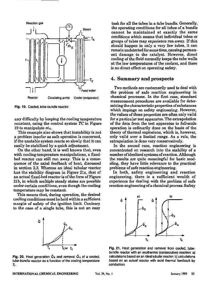
Strongly exothermic reactions and reactions which are susceptible to running away, such as partial oxidations, are usually carried out in tubebundle, fixed-bed reactors, since the temperature of the reactor has to be kept within narrow limits. Figure 19 shows a typical reactor and cooling circuit. The main part of the coolant, a highboiling, organic liquid or a molten salt, is pumped through the jacket around the tube bundles by means of a circulating pump. The heat removed is used to produce process steam, with part of the flux niK being introduced into the cooler (or evaporator). Assuming that this stream is thereby cooled from Tc to a constant temperature Ts, which depends solely on the saturated vapor pressure, the quantity Q A extracted is given by
(15)
The quantity QE of heat generated by the reaction increases exponentially with the temperature in the customary way. Under normal steadystate operation, both quantities of heat must be equal. This leads to Figure 20 for strongly exothermic reactions. The desired operating point TC,5011 is unstable, but stability is achieved without
22 January 1989 Vol. 29, No.1 INTERNATIONAL CHEMICAL ENGINEERING
Reaction gas
;'
I Feed water
Reactor Circulating pump Cooler (evaporator)
Fig. 19. Cooled, tube-bundle reactor.
any difficulty by keeping the cooling temperature constant, using the control system TC in Figure 19 to manipulate mK.
This example also shows that instability is not a problem insofar as safe operation is concerned, ifthe unstable system reacts so slowly that it can easily be stabilized by a quick adjustment.
On the other hand, it is well known that, even with cooling-temperature manipulations, a fixedbed reactor can still run away. This is a consequence of the axial feedback of heat, discussed in section 2.3. Whereas an ideal tubular reactor has the stability diagram in Figure 21a, that of an actual fixed-bed reactoris ofthe form of Figure 21b, in which multiple steady states are possible under certain conditions, even though the cooling temperature may be constant.
This means that, during operation, the desired cooling conditions must be held within a sufficient margin of safety of the ignition limit. Contrary to the case of a single tube, this is not an easy
Ts Tc,ScI Tc
Fig. 20. Heat generation OE and removal OA of a cooled, tube-bundle reactor as a function of the cooling temperature Tc.
task for all the tubes in a tube bundle. Generally, the operating conditions for all tubes of a bundle cannot be maintained at exactly the same conditions which means that individual tubes or groups of tubes may experience run·away. If this should happen in only a very few tubes, it can remain undetected for some time, causing permanent damage to the catalyst. However, direct cooling of the fluid normally keeps the tube walls at the low temperatures of the coolant, and there is no direct effect on operating safety.
4. Summary and prospects
Two methods are customarily used to deal with the problem of safe reaction engineering in chemical processes. In the first case, standard measurement procedures are available for determining the characteristic properties of substances which impinge on safety engineering. However, the values of these properties are often only valid for a particular test apparatus. The extrapolation of the data from the test apparatus to full-scale operation is ordinarily done on the basis of the theory of thermal explosions, which is, however, only valid over a limited range. As a rule, the extrapolation is done very conservatively.
In the second case, reaction engineering is concentrated on research into the stability of a number of idealized systems of reaction. Although the results are quite meaningful for basic mod· eling, they have little relevance to the practical problems of safe reaction-engineering.
In both, safety engineering and reaction engineering, there is a sufficient wealth of experience for dealing with the problem of safe reaction-engineering of a chemical process. Safety
a) b)
Fig. 21. Heat generation and removal from cooled, tubebundle reactor with an exothermic (consecutive) reaction: a) calculations based on an ideal tubular reactor, b) calculations based on an actual reactor with axial thermal feedback by conduction.
INTERNATIONAL CHEMICAL ENGINEERING Vol. 29, No. I January 1989 23

engineering offers its wealth of empirical evidence, while reaction engineering provides the theoretical and nUlllerical tools of mathematical modeling. One of the objectives of the foregoing article is to hasten this symbiosis.
Nomenclature
A C Co Cs E (-AHR) ntK N N; QA QE R S T Tcrit
Tc T~ 7'g Tmax To Ts Ts TSoll
Tz A Tad
U
V Xmax
Cp
CpK
ko ntK q r t A tad
zlv
{j
p
cooling surface concentration of a key component concentration in feed steady-state concentration energy of activation enthalpy of reaction rate of mass flow of coolant cooling intensity mass of reactant i heat removal line heat generation curve universal gas constant characteristic constant of reaction temperature critical temperature cooling temperature critical cooling temperature equilibrium temperature maximum temperature feed or initial temperature steady-state temperature saturated vapor temperature temperature of set point temperature for ignition adiabatic rise in temperature heat transfer coefficient, or conversion of component i volume of reactor maximum dimensionless rise in temperature specific heat of reacting mixture specific heat of coolant preexponential factor mass flux of coolant volumetric rate of inflow rate of reaction time adiabatic time of induction residence time (z length of tube, v velocity) Kronecker delta function density
Literature cited
1. Frank-Kamenetzki, D. A., Stoff- und Wiirmeilbertragung in der chemischen
Kinetik (Mass and Heat Transfer in Chemical Kinetics), Springer-Verlag, Berlin (1959).
2. Semonov, N. N., Einige Probleme der chemis chen Kinetik und Reaktionsfiihigkeit (Some Problems in Chemical Kinetics and Reactivity), Akademie-Verlag, Berlin (1961).
3. Gray, P. and Lee, P. R, Oxid. Combust. Rev. 2, pp. 1-183 (1967).
4. Uppal, A., Ray, W. H., and Poore, A. B., Chem. Eng. Sci. 29, pp. 967·985 (1974).
5. Uppal, A., Ray, W. H., and Poore, A. B., Chem. Eng. Sci. 31, pp. 205·214 (1976).
6. Vaganov, D. A., Samoilenko, N. G., and Abramov, V. G., Chem. Eng. Sci. 33, pp. 1133-1140 (1978).
7. Aris, R. and Amundson, N. R, Chem. Eng. Sci. 7, pp. 121-147 (1985).
8. Semonov, N. N., Z. Phys. 48, pp. 571-582 (1928).
9. Grewer, T., Chem.-Ing.-Tech. 47, pp. 230-236 (1975).
10. Berthold, w., Heckle, M., LUdecke, H. J., and Zieger, A., Chem.-Ing.-Tech. 47, pp. 368-373 (1975).
11. Barkelew, C. H., Chem. Eng. Progr., Symp. Ser. 55, pp. 37-47 (1959).
12. Froment, G. F., Front. Chem. React. Eng. 1, pp. 12-38 (1984).
13. HlavMek, V., Ind. Eng. Chem. 62, pp. 8-26 (1970).
14. Westerterp, K. R. and Overtoom, R R. M., Chem. Eng. Sci. 40, pp. 155-165 (1985).
15. Schuler, H., Regelungstechnik 32, pp. 190-200 and 234-237 (1984).
16. King, R. and Gilles, E. D., DECHEMAMonogr. 100, pp. 149-171 (1985).
17. Jensen, K. F. and Ray, W. H., Chem. Eng. Sci. 37, pp. 199-222 (1982).
18. Eigenberger, G., Chem.-Ing.-Tech. 50, pp. 924-933 (1978).
19. Gilles, E. D. and Eigenberger, G., DECHEMAMonogr. 94, pp. 281-311 (1983).
20. Hugo, P., Ghem:-Ing.-Tech. 53, pp. 107-109 (1981).
21. Hugo, P. and Steinbach, J., Chem.-Ing.Tech. 57, pp. 780-782 (1985).
22. Steinbach, J., Dissertation, TU Berlin (1985).
23. Schuler, H., Technisches Messen 53, No. 71 8, pp. 299-304 (1980).
24. Bratz, W. and Schobucher, A., Technische Chemie I (Applied Chemistry n, Cap. 4.2.1, VCH Verlagsgesellschaft, Weinheim (1982).
24 January 1989 Vol. 29, No.1 INTERNATIONAL CHEMICAL ENGINEERING
25. Ankel, T., Regelung von Reaktoren (control of Reactors), in: Messen, Steuern und Regeln in der Chemischen Technik (Measurement, Control, and Regulation in
INTERNATIONAL CHEMICAL ENGINEERING Vol. 29, No. I
Chemical Engineering), Hengstenberg, J., Sturm, B., and Winkler, O. (Eds.), 3rd Edn., Vol. III, pp. 378 ff, Springer-Verlag, Berlin (1981).
January 1989 2S