Embed Size (px)
Citation preview
This version has been archived.
For the latest version of this document, visit:
https://docs.aws.amazon.com/whitepapers/latest/reactive-systems-on-aws/reactive-systems-on-aws.html
Reactive Systems on AWS
November 1, 2021
This version has been archived.
For the latest version of this document, visit:
https://docs.aws.amazon.com/whitepapers/latest/reactive-systems-on-aws/reactive-systems-on-aws.html
Notices
Customers are responsible for making their own independent assessment of the
information in this document. This document: (a) is for informational purposes only, (b)
represents current AWS product offerings and practices, which are subject to change
without notice, and (c) does not create any commitments or assurances from AWS and
its affiliates, suppliers or licensors. AWS products or services are provided “as is”
without warranties, representations, or conditions of any kind, whether express or
implied. The responsibilities and liabilities of AWS to its customers are controlled by
AWS agreements, and this document is not part of, nor does it modify, any agreement
between AWS and its customers.
© 2021 Amazon Web Services, Inc. or its affiliates. All rights reserved.

This version has been archived.
For the latest version of this document, visit:
https://docs.aws.amazon.com/whitepapers/latest/reactive-systems-on-aws/reactive-systems-on-aws.html
Contents
Introduction .......................................................................................................................... 1
Characteristics of reactive systems .................................................................................... 2
Responsive ....................................................................................................................... 2
Resilient ............................................................................................................................ 2
Elastic ............................................................................................................................... 2
Message driven ................................................................................................................ 2
Observability and tracing ................................................................................................. 3
Reactive programming and reactive streams .................................................................. 4
Typical use-cases for reactive systems .............................................................................. 5
Example architecture ........................................................................................................... 6
Using an event driven and non-blocking framework ....................................................... 8
The reactive manifesto and AWS services ....................................................................... 10
Service introduction ........................................................................................................ 10
Principles and services .................................................................................................. 11
Conclusion ......................................................................................................................... 23
Contributors ....................................................................................................................... 23
Further reading .................................................................................................................. 24
Document revisions ........................................................................................................... 24
This version has been archived.
For the latest version of this document, visit:
https://docs.aws.amazon.com/whitepapers/latest/reactive-systems-on-aws/reactive-systems-on-aws.html
Abstract
Today, architects and developers are expected to implement highly scalable and
resilient distributed system on Amazon Web Services (AWS). This whitepaper outlines
best practices for designing a system based on reactive principles using the AWS Cloud
platform and offers a reference architecture to guide organizations in the delivery of
these systems.

This version has been archived.
For the latest version of this document, visit:
https://docs.aws.amazon.com/whitepapers/latest/reactive-systems-on-aws/reactive-systems-on-aws.html
Amazon Web Services Reactive Systems on AWS
1
Introduction
Microservice application requirements have changed dramatically in recent years. Many
modern applications are expected to handle petabytes of data, require close to 100%
uptime, and deliver sub-second response time to users. Typical N-tier applications can’t
deliver on these requirements. Today reactive architectures and reactive systems have
been adopted by a growing number of enterprises, because it is necessary to design
applications in a highly scalable and responsive way. But what exactly is a reactive
system?
The Reactive Manifesto, describes the essential characteristics of reactive systems
including: responsiveness, resiliency, elasticity, and being message driven.
Being message driven is perhaps the most important characteristic of reactive systems.
Asynchronous messaging helps in the design of loosely coupled systems, which is a
key factor for scalability. In order to build highly resilient systems, it is important to
isolate services from each other. Microservices are an architectural and organizational
approach to software development where software is composed of small independent
services that communicate over well-defined APIs. These services are owned by small,
self-contained teams. Isolation and decoupling are an important aspect of the
microservices pattern as well. This makes reactive systems and microservices a natural
fit.
This version has been archived.
For the latest version of this document, visit:
https://docs.aws.amazon.com/whitepapers/latest/reactive-systems-on-aws/reactive-systems-on-aws.html
Amazon Web Services Reactive Systems on AWS
2
Characteristics of reactive systems
The following sections outline the essential characteristics of reactive systems.
Responsive
Responsiveness means that systems respond in a timely manner. It is crucial to reduce
latency between request and response. Latency is an important factor that can, under
certain circumstances, be decisive for the success or failure of a service. It directly
influences the behavior of the consumer of the website or webservice. Imagine, you
want to check out your shopping cart on an e-commerce website and processing of the
payment takes a significant amount of time or even crashes. This results in an overall
bad user experience. Latency is often correlated with conversion rate. Responding in a
timely manner ensures these systems deliver a consistent behavior and quality of
service.
Resilient
A resilient system stays responsive in the face of failure. A resilient workload has the
capability to recover when stressed by load, attacks, and failure of any component in
the workload's components. If a failure occurs in one component, this must be
contained in the source of the failure by isolating it from others. As a result, this
prevents a small failure from causing a major outage of the complete system.
Elastic
A reactive architecture remains responsive under varying workload. This elasticity
requires you to be able to scale a system dynamically and add or remove resources to
react to changes which leads to the avoidance of bottlenecks. These systems support
predictive as well as reactive scaling based on metrics which leads to an efficient use of
resources.
Message driven
In order to establish boundaries between services, reactive systems rely on
asynchronous message-passing. This helps ensure loose coupling, isolation, and
location transparency. Location transparency can be achieved by using a message
queue or a similar system to access data without the explicit knowledge of the location.
This can be achieved using network resources like DNS. The main advantage of this
approach is that it’s not important where exactly the resource is located. This is key for

This version has been archived.
For the latest version of this document, visit:
https://docs.aws.amazon.com/whitepapers/latest/reactive-systems-on-aws/reactive-systems-on-aws.html
Amazon Web Services Reactive Systems on AWS
3
resiliency and elasticity, because a failover mechanism can be implemented that
abstracts the actual resource behind a network name. In reactive systems,
asynchronous message-passing is also used to distribute information of failures or other
errors as messages. By using this pattern, the system enables better load management
by monitoring the message queues and implementing a mechanism for backpressure.
This allows non-blocking communication which leads to less system overhead. One of
the biggest challenges to effectively scale large systems is the bottleneck that is
introduced by shared resources. This communication pattern helps minimizing
concurrent access.
But what’s the difference between message-driven and event-driven? According to K.
Mani Chandy, Professor of Computer Science at the California Institute of Technology,
events can be defined as a significant change in state1. An event can be a change in an
AWS environment. For example, Amazon EC2 Auto Scaling generates events when it
launches or terminates instances. A message however has a clear direction: it’s a
command sent to a system. The destination reacts on the message and starts an
action.
Observability and tracing
As already outlined, reactive systems are defined as message-driven and resilient,
which means, a reactive system - by nature - will be a distributed system. This
necessarily includes additional network communication. In a traditional monolithic
application (for example, a JavaEE application) the complete application resides in the
same memory on one device, potentially with full redundant copies on other machines
to allow for failover. In many cases, monolithic applications have better latency
compared to distributed application but with limitations in scalability and availability. The
example application discussed later shows patterns and best practices to reduce
latency, but in many cases, workloads that have very low latency requirements such as
high-frequency trading, are not good candidates for reactive systems. Due to the
distributed nature of reactive systems that involve communication over network and
across server-boundaries, the additional latency has a huge impact on the performance
of the overall application.
If there is an error in a traditional monolithic application, for example an exception was
found in one of the log files, debugging this problem is often relatively easy due to the
non-distributed nature of the application. A typical microservices based application that
passes messages for communication is harder to debug, because it is sometimes not
possible to reproduce the exact state of the complete system and replay events in order
This version has been archived.
For the latest version of this document, visit:
https://docs.aws.amazon.com/whitepapers/latest/reactive-systems-on-aws/reactive-systems-on-aws.html
Amazon Web Services Reactive Systems on AWS
4
to reproduce issues. Each service has a separate log file, even though those log files
are often consolidated in a central system such as Amazon CloudWatch Logs or
Amazon OpenSearch Service. An additional critical piece of the puzzle is to correlate an
event with a specific set of log entries. Each event needs a unique identifier which
needs to be logged on each step of its journey through different microservices. You can
add the following tracing header to incoming HTTP requests that don't already have one
using services such as Application Load Balancer or Amazon API Gateway:
X-Amzn-Trace-Id: Root=1-5759e988-bd862e3fe1be46a994272793
This tracing header can be used to correlate events with log entries. In addition, you can
use services such as AWS X-Ray to trace and analyze requests as they travel through
your entire system, from Application Load Balancer or Amazon API Gateway APIs to
the underlying services, making it much easier to identify issues and visualize service
calls. AWS X-Ray helps developers analyze and debug production, distributed
applications, which are built using a microservices architecture. X-Ray’s service maps
let you see relationships between services and resources in your application in real
time. You can easily detect where high latencies are occurring, visualize node and edge
latency distribution for services, and then drill down into the specific services and paths
impacting application performance.
Reactive programming and reactive streams
It is important to make a distinction between reactive systems and reactive
programming because these two completely different concepts are often confused.
Reactive systems are responsive, resilient, elastic, and message driven as per
preceding paragraphs. This description shows that reactive systems are an architectural
approach to design distributed responsive systems. Reactive programming, however, is
a software design approach which focusses on asynchronous data streams. Everything
in the application is seen as a stream of data which can be observed (observer pattern).
An interesting approach to simplify the challenges of reactive programming are Reactive
eXtensions , an “API for asynchronous programming with observable streams”.
Reactive Programming can help to build a system based on the principles of the
Reactive Manifesto, but the use of reactive programming doesn’t necessarily mean that
a system is reactive.
Reactive Streams is an initiative to define a standard for asynchronous stream
processing with non-blocking backpressure. The main goal of this concept is to control
the exchange of streaming data across an asynchronous boundary. Backpressure is an
This version has been archived.
For the latest version of this document, visit:
https://docs.aws.amazon.com/whitepapers/latest/reactive-systems-on-aws/reactive-systems-on-aws.html
Amazon Web Services Reactive Systems on AWS
5
integral part of this model: The recipient is only sent as much data as it can process or
buffer in and the receiver explicitly requests the data according to its capacity. This
means, the sender may only send as much data as the receiver has requested.
The goal behind the Reactive Streams’ specification is to create the basis for
compatible implementations that can communicate with each other. This specification
includes a minimal set of interfaces, methods, and protocols, that define operations and
entities that are necessary to implement a compatible version.
Typical use-cases for reactive systems
In the previous section, the essential characteristics of reactive systems was outlined.
What do typical use cases for reactive systems have in common? Potentially millions of
messages flow into the backend system. The impact of this requirement is a backend
system that is able to quickly scale out and is resilient.
Advertising technology (Ad tech) face an interesting challenge to collect or track a lot of
information. Usually this is a tracking pixel on a website that ingests data into a system.
Depending on the campaign and its success, the amount of data that needs to be
collected and transformed may significantly vary and is not always predictable. The
following sections take a closer look at an example implementation for a tracking
system for ads.
For eCommerce, it’s a similar situation: if a product goes viral on social media or an
advertising campaign is surprisingly successful, a lot of people will visit the eCommerce
website and order products.
For IoT, you need to be able to manage millions of connected devices that produce a
huge amount of sensor data. This data needs to be collected, stored, and analyzed.
Often it is necessary to send additional data back to the connected devices to update
the status. The complete system has to be responsive in order to deliver feedback to
users or trigger changes in the devices or machines within a short span of time.
This version has been archived.
For the latest version of this document, visit:
https://docs.aws.amazon.com/whitepapers/latest/reactive-systems-on-aws/reactive-systems-on-aws.html
Amazon Web Services Reactive Systems on AWS
6
Example architecture
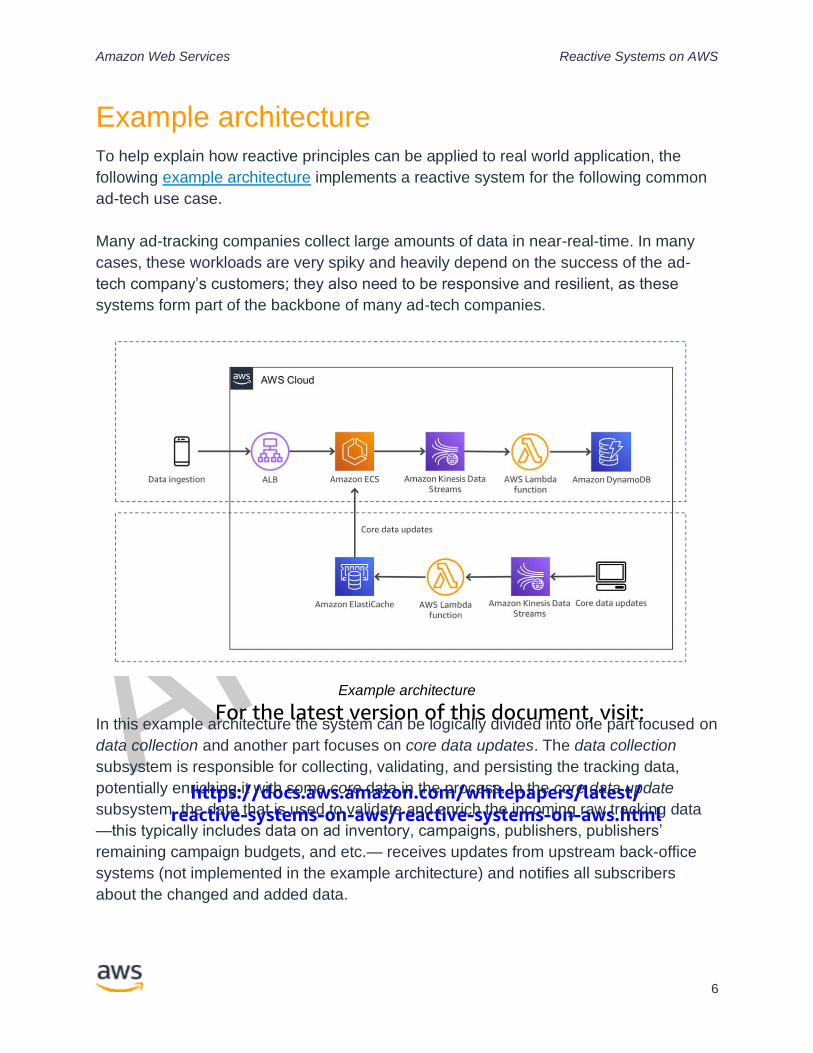
To help explain how reactive principles can be applied to real world application, the
following example architecture implements a reactive system for the following common
ad-tech use case.
Many ad-tracking companies collect large amounts of data in near-real-time. In many
cases, these workloads are very spiky and heavily depend on the success of the ad-
tech company’s customers; they also need to be responsive and resilient, as these
systems form part of the backbone of many ad-tech companies.
Example architecture
In this example architecture the system can be logically divided into one part focused on
data collection and another part focuses on core data updates. The data collection
subsystem is responsible for collecting, validating, and persisting the tracking data,
potentially enriching it with some core data in the process. In the core data update
subsystem, the data that is used to validate and enrich the incoming raw tracking data
—this typically includes data on ad inventory, campaigns, publishers, publishers’
remaining campaign budgets, and etc.— receives updates from upstream back-office
systems (not implemented in the example architecture) and notifies all subscribers
about the changed and added data.

This version has been archived.
For the latest version of this document, visit:
https://docs.aws.amazon.com/whitepapers/latest/reactive-systems-on-aws/reactive-systems-on-aws.html
Amazon Web Services Reactive Systems on AWS
7
Typically for an ad-tracking use case, the data collection subsystem can be separated
further into a real-time part and a non-real-time part. For the real-time part, it is most
important to collect data as quickly as possible and ask several questions such as:
• Is this a valid combination of parameters?
• Does this campaign exist?
• Is this campaign still valid?
Because response time has a huge impact on conversion rate in advertising, it is
important for advertisers to respond as quickly as possible. Any information required to
decide on a response should be kept in memory to reduce communication overhead
with the caching infrastructure. The tracking application itself should be as lightweight
and scalable as possible. For example, the application shouldn’t have any shared
mutable state. In the example architecture, one main application running in Amazon
ECS is responsible for the real-time part, which collects and validates data, responds to
the client as fast as possible, and asynchronously sends events to backend systems.
The non-real-time part of the application consumes the generated events and persists
them in a NoSQL database. In a standard tracking implementation this includes clicks,
cookie information, and transactions; once stored, these are later matched
asynchronously and persisted in a data store. At the time of publication, matching is not
implemented in the example architecture. However, you can use big-data frameworks
like Hadoop or Spark for the matching implementation. The results of this matching
process and other back-office processes (fraud checks, billing of providers of ad
inventory, payouts to ad space providers, and etc.) often result in updates to the core
data, and is then fed back into the core data updates subsystem via an event stream.
In the example architecture shown in the architecture diagram, the request (ad
impression or clicked ad) is ingested to the Application Load Balancer which routes the
incoming request to one of the service instances in the main application. The L1 cache
– which is stored in the memory of the application - stores the most recent core data
updates. In addition, there is an open connection to the L2 cache. The application
processes each incoming request separately. It is implemented in a responsive and
resilient manner and doesn’t write directly to a database: using Amazon Kinesis Data
Streams new events are added to a data stream and consumed by an AWS Lambda
function which writes the data into an Amazon DynamoDB table. The data stream –
implemented with Amazon Kinesis Data Streams - acts as a main buffer to decouple the
database from the application and ensure that this event data under load isn’t lost.

This version has been archived.
For the latest version of this document, visit:
https://docs.aws.amazon.com/whitepapers/latest/reactive-systems-on-aws/reactive-systems-on-aws.html
Amazon Web Services Reactive Systems on AWS
8
With this architecture you can reliably process a huge number of events and store them
safely. The application does not live in a vacuum - typically, it needs to rely on other
data that is not present in the event. In the ad tech example, this core data would
include information about the available event inventory, the ad publishers, their budgets
and preferences, etc. This data lives in a variety of upstream systems - the challenge is
that it needs to be available to our application at any time and without having to wait for
the source system. To reduce latency of access to this core data and to simplify the
architecture, Amazon ElastiCache for Redis is used as the main interface, which means
all the necessary data is cached for the application. As with any cache, you still need to
track updates to our core data sets. These source systems are out of scope for this
whitepaper, but assume that you get update events whenever something changes. In
this situation, you rely on message-passing. The application offers an event stream that
all the source systems can write to whenever they see a change. This offers a fairly
minimal interface to the outside world and decouples it from our system; using Kinesis
Data Streams you can handle various request rates without having to worry a lot about
the infrastructure. In some situations, you might have to deal with different request rates
and many different types of data, depending on how many source systems the core
data comes from. Similar to how this is done in the main event pipeline, you can use a
Lambda function to have an elastic, resilient processing mechanism to process new
data on the stream and updates the main cache to make it available to the application.
Using an event driven and non-blocking framework The main application in the example architecture, is using a framework called Eclipse
Vert.x, which is a toolkit for building reactive applications on the JVM. Vert.x is event
driven and non-blocking. This means Vert.x applications can handle a large number of
concurrent connections using a small number of kernel threads. The same or similar
patterns and paradigms can be used with Akka, Micronaut or other frameworks. Vert.x
uses a simple, scalable, actor-like deployment and concurrency model based on so
called verticles which are chunks of code extending an abstract class. Due to the
polymorphic nature of Vert.x, verticles can be implemented in different languages and a
single application can consist of verticles written in multiple languages. The verticles
communicate with each other using the event bus - which supports publish/subscribe,
point-to-point, and request-response messaging - by sending messages. In the example
architecture this means that is has the same architectural principles on a micro- as well
as on a macro-level. The different parts of the architecture communicate by exchanging
messages and this also applies to the internal communication of the main application.
In most cases Vert.x calls your handlers using a thread called an event loop. Aside from
This version has been archived.
For the latest version of this document, visit:
https://docs.aws.amazon.com/whitepapers/latest/reactive-systems-on-aws/reactive-systems-on-aws.html
Amazon Web Services Reactive Systems on AWS
9
the updates to the external Redis cache the application also keeps its own L1, in-
process cache. Whenever the Redis cache is updated, you need to update the in-
process cache. Going with the design principles you will want to get these updates
pushed into the application. But why is it necessary to store data in a L1-cache? This is
important to distribute core data changes using Redis, because it is necessary to
reduce the number of accesses to the L2-cache. After 10 minutes the data is
automatically invalidated and a data refresh is necessary. This behavior is a trade-off,
because you might run into situation where you have to deal with stale data. Doing so
also protects the application from failures that cause the Redis cluster to become
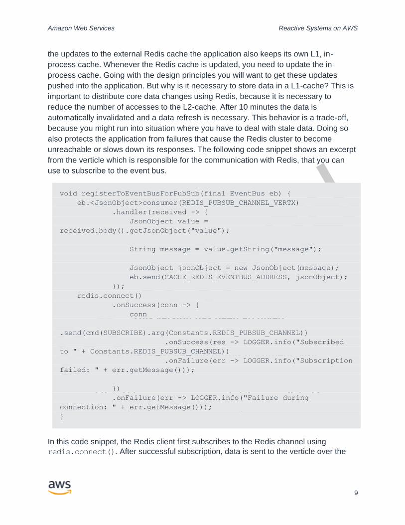
unreachable or slows down its responses. The following code snippet shows an excerpt
from the verticle which is responsible for the communication with Redis, that you can
use to subscribe to the event bus.
void registerToEventBusForPubSub(final EventBus eb) {
eb.<JsonObject>consumer(REDIS_PUBSUB_CHANNEL_VERTX)
.handler(received -> {
JsonObject value =
received.body().getJsonObject("value");
String message = value.getString("message");
JsonObject jsonObject = new JsonObject(message);
eb.send(CACHE_REDIS_EVENTBUS_ADDRESS, jsonObject);
});
redis.connect()
.onSuccess(conn -> {
conn
.send(cmd(SUBSCRIBE).arg(Constants.REDIS_PUBSUB_CHANNEL))
.onSuccess(res -> LOGGER.info("Subscribed
to " + Constants.REDIS_PUBSUB_CHANNEL))
.onFailure(err -> LOGGER.info("Subscription
failed: " + err.getMessage()));
})
.onFailure(err -> LOGGER.info("Failure during
connection: " + err.getMessage()));
}
In this code snippet, the Redis client first subscribes to the Redis channel using
redis.connect(). After successful subscription, data is sent to the verticle over the
This version has been archived.
For the latest version of this document, visit:
https://docs.aws.amazon.com/whitepapers/latest/reactive-systems-on-aws/reactive-systems-on-aws.html
Amazon Web Services Reactive Systems on AWS
10
event bus. The verticle unwraps the data and sends it to the caching verticle to store the
data in the L1-cache. This is a very fast and lightweight implementation and you can
reuse existing infrastructure, because Redis is already being used for caching
purposes.
The reactive manifesto and AWS services
The following section focuses on how to map compute and messaging services to the
four principles of the reactive manifesto. This section only focuses on a limited set of
services which are also used in the example implementation examined in the last
chapter.
Service introduction
Amazon ECS
Amazon Elastic Container Service (Amazon ECS) is a fully managed container
orchestration service. It is a shared state, optimistic concurrency system that provides
flexible scheduling capabilities for your tasks and containers. In the reference
architecture, Amazon ECS with AWS Fargate is used to run the main application which
is implemented using Java. One of the objectives in the development of the application
was to keep the latency as low as possible, because in this part increased latency has a
negative impact on the conversion rate. For this particular use case, it’s recommended
to use Amazon ECS instead of AWS Lambda. If the different components of the
application were split into individual Lambda functions and these were orchestrated with
AWS Step Functions, this would have a negative impact on latency, which is not a
problem for many use cases, but in this particular case, keeping latency as low as
possible is a very important aspect of the overall application.
Amazon EKS
Amazon Elastic Kubernetes Service (Amazon EKS) gives you the flexibility to start, run,
and scale Kubernetes applications in the AWS Cloud or on-premises. Amazon EKS
helps you provide highly-available and secure clusters and automates key tasks such
as patching, node provisioning, and updates. Amazon EKS was not used for the
implementation of the sample architecture; however, it is possible to use Amazon EKS
instead of Amazon ECS.
AWS Lambda
AWS Lambda is a serverless compute service that lets you run code without
provisioning or managing servers, creating workload-aware cluster scaling logic,
This version has been archived.
For the latest version of this document, visit:
https://docs.aws.amazon.com/whitepapers/latest/reactive-systems-on-aws/reactive-systems-on-aws.html
Amazon Web Services Reactive Systems on AWS
11
maintaining event integrations, or managing runtimes. With Lambda, you can run code
for virtually any type of application or backend service - all with zero administration.
AWS Lambda's role in the example architecture is to receive messages from the
Amazon Kinesis Data Stream, which is very low implementation overhead. Lambda
integrates natively with Kinesis Data Streams. The polling, checkpointing, and error
handling complexities are abstracted when using this integration. This allows the
Lambda function code to focus on business logic processing.
Amazon Kinesis Data Streams
Amazon Kinesis Data Streams is a massively scalable and durable real-time data
streaming service. In this architecture, Kinesis Data Streams is used to decouple key
application components, such as processing incoming data and persisting the enriched
data in Amazon DynamoDB. This split is possible because the writing of the data can be
done asynchronously, while the response to the requesting client should happen as
quickly as possible.
Amazon ElastiCache
Amazon ElastiCache offers a fully managed in-memory data store, compatible with
Redis or Memcached that enables you to power real-time applications with sub-
millisecond latency. The service can scale-out, scale-in, and scale-up to meet
fluctuating application demands. Write and memory scaling is supported with sharding.
In this architecture, Redis is used in two different ways: source for core data, and
pub/sub implementation to actively update the L1-cache in the main application.
Amazon DynamoDB
Amazon DynamoDB is a key-value and document database that delivers single-digit
millisecond performance at any scale. It is a fully managed database with scalability and
high availability built in. DynamoDB is used in this architecture as the central repository
for the result data, since DynamoDB is fully managed, multi-region, multi-active, durable
database for internet-scale applications.
Principles and services
Responsive
As previously mentioned, being responsive means that systems respond in a timely
manner, even under heavy load. To meet this requirement, special attention must be
paid to latency. In the example architecture, an Application Load Balancer serves as the
single point of contact for clients. The load balancer distributes incoming application

This version has been archived.
For the latest version of this document, visit:
https://docs.aws.amazon.com/whitepapers/latest/reactive-systems-on-aws/reactive-systems-on-aws.html
Amazon Web Services Reactive Systems on AWS
12
traffic across multiple targets, such as EC2 instances, in multiple Availability Zones.
This increases the availability of your application, and you can add one or more
listeners to your load balancer. Elastic Load Balancing publishes data points to Amazon
CloudWatch for your load balancers and your targets. CloudWatch enables you to
retrieve statistics about those data points as an ordered set of time-series data, known
as metrics. You can think of a metric as a variable to monitor, and the data points as the
values of that variable over time. For example, you can monitor the total number of
healthy targets for a load balancer over a specified time period. Application Load
Balancer exposes the metric TargetResponseTime which is the time elapsed (in
seconds) after the request leaves the load balancer until a response from the target is
received. Based on this metric, it is possible to scale out the number of services running
in an Amazon ECS cluster by defining Amazon CloudWatch Alarms.
Another important component for reducing latency is the use of caches. At this point you
have to differentiate between an in-memory cache inside the application and external
caches such as Redis or Memcache, which are offered as a managed service within the
framework of Amazon ElastiCache. In-memory caches can be used directly in the
application via corresponding libraries. Depending on the extent to which outdated data
can be tolerated, this type of cache should be updated shortly after records are
changed, and can be implemented via a pub/sub mechanism. In addition, a least-
recently-used (LRU) strategy and the limitation of cache entries in terms of quantity and
time are also useful. There are several strategies and picking the right caching strategy
has a huge impact on the overall performance of the system.
The following section outlines popular caching strategies:
Cache-aside
The cache-aside strategy is one of the most common design patterns for cache access.
The cache sits next to the database and first the cache is checked to see if a value is
found there. If it is not there, the database is queried and the value is then stored in the
cache. This means, data is read lazily on first read. One major advantage of this
strategy is that the architecture is resilient to cache failures: if your cache fails, the
system can still work, but it will have a major impact on response time and latency. It is
a common best practice to invalidate cache entries if data is updated or deleted. In
addition, a time to live (TTL) is used to automatically invalidate cache entries.
Read-through
This read-through strategy is similar to cache-aside, one major difference is that the
cache is responsible for reading from the database. With a read-through cache, this is
This version has been archived.
For the latest version of this document, visit:
https://docs.aws.amazon.com/whitepapers/latest/reactive-systems-on-aws/reactive-systems-on-aws.html
Amazon Web Services Reactive Systems on AWS
13
used as a central storage for data: all read accesses go to the cache. If no entry is
found when reading, the missing data is fetched from the database by the cache. A
read-through cache loads data lazily if the data if accessed for the first time.
Write-through
The write-through strategy ensures that entries that are written into the cache are also
put into the central storage behind it (for example, a database). Amazon DynamoDB
Accelerator (DAX) is a write-through caching service that is designed to simplify the
process of adding a cache to DynamoDB tables. Because DAX operates separately
from DynamoDB, it is important that you understand the consistency models of both
DAX and DynamoDB to ensure that your applications behave as you expect. Usually,
write-through caches are combined with read-through caches, because an isolated
write-through cache will only introduce additional latency.
Write-back (write-behind)
The write-back strategy, stores entries directly in the cache by the application and after
a delay are stored in a database. This type of caching is particularly suitable for write-
intensive applications, because services don’t have to wait for data being persisted to
the database. Database updates can be stored in a queue and applied asynchronously.
Often this pattern is combined with a read-through cache if the workload is read- and
write-heavy.
All of these caching strategies have advantages and disadvantages, which can be
mitigated by appropriate logic (invalidation, pre-warming etc.). Therefore, additional
logic is necessary, which has to be implemented and tested.
Resilient
Everything fails, all the time.
- Werner Vogels (CTO, Amazon.com)
According to the AWS Well-Architected Framework, resiliency is “The ability for a
system to recover from a failure induced by load, attacks, and failures”. Depending on
the service used, resiliency is either part of the service offering or has to be designed by
the customer, depending on the specific requirements. The following section discusses
resiliency for different AWS services and how this can be implemented.

This version has been archived.
For the latest version of this document, visit:
https://docs.aws.amazon.com/whitepapers/latest/reactive-systems-on-aws/reactive-systems-on-aws.html
Amazon Web Services Reactive Systems on AWS
14
AWS Global Infrastructure
The AWS Global Infrastructure consists of multiple building blocks that provide different
levels of independent, redundant components. AWS partitions resources and requests
via some dimension. These partitions or cells are designed to be independent and in the
case of an error, contain faults to within a single cell. For example, Amazon Route53
uses the concept of shuffle sharding to isolate customer requests into cells.
AWS also offers the fault isolation construct of Availability Zones (AZs). Each AWS
Region consists of multiple, isolated, and physically separate AZs within a geographic
area. Each AZ is separated by a large physical distance from other zones to avoid
correlated failure scenarios. An AZ consists of one or more discrete data centers with
redundant power, networking, and connectivity in an AWS Region. Despite being
geographically separated, Availability Zones are located in the same regional area. This
enables customers to use AZs in an active/active or active/standby configuration. Some
AWS services are deployed as strictly zonal services. These services are used to
independently operate resources (instances, databases, and other infrastructure) within
the specific AZ.
While AWS control planes typically provide the ability to manage resources at a regional
level (multiple AZs), certain control planes (including Amazon EC2 and Amazon EBS)
have the ability to filter results to a single Availability Zone.
The most pervasive fault isolation construct is that of the AWS Region. Regions are
designed to be autonomous, with dedicated copies of services deployed in each region.
Regional AWS services internally use multiple Availability Zones in an active/active
configuration to achieve the availability design goals you establish.
AWS Lambda
In addition to the benefits of the AWS global infrastructure, AWS Lambda offers several
features to help support your data resiliency and backup needs. Lambda runs instances
of your function in multiple AZs to ensure that it is available to process events in case of
a service interruption in a single zone. If you configure your function to connect to a
virtual private cloud (VPC) in your account, specify subnets in multiple AZs to ensure
high availability. To make sure that your function can always scale to handle additional
requests, you can reserve concurrency for it. Setting reserved concurrency for a
function ensures that it can scale to, but not exceed, a specified number of concurrent
invocations. This ensures that you don't lose requests due to other functions consuming
all of the available concurrency. For asynchronous invocations and a subset of
invocations triggered by other services, Lambda automatically retries on error with
This version has been archived.
For the latest version of this document, visit:
https://docs.aws.amazon.com/whitepapers/latest/reactive-systems-on-aws/reactive-systems-on-aws.html
Amazon Web Services Reactive Systems on AWS
15
appropriate delays between retries. Other clients and AWS services that invoke
functions synchronously are responsible for performing retries. In addition, you can
configure Lambda to send requests to a dead-letter queue if all retries fail for
asynchronous invocations. A dead-letter queue is an Amazon Simple Notification
Service (Amazon SNS) topic or Amazon Simple Queue Service (Amazon SQS) queue
that receives events for troubleshooting or reprocessing. You can use versioning in
Lambda to save your function's code and configuration as you develop it. Together with
aliases, you can use versioning to perform blue/green and rolling deployments.
Amazon ECS
Amazon Elastic Container Service (Amazon ECS) schedulers leverage the same cluster
state information provided by the Amazon ECS API to make appropriate placement
decisions. A task placement strategy is an algorithm for selecting instances for task
placement or tasks for termination. A task placement constraint is a rule that is
considered during task placement. For example, you can use constraints to place tasks
based on AZ or instance type. Amazon ECS supports two launch types that determine
how instances of tasks (containers) are being launched:
Each task that uses the AWS Fargate launch type has its own isolation boundary and
does not share the underlying kernel, CPU resources, memory resources, or elastic
network interface with another task. AWS Fargate is a serverless compute engine for
containers that works with both Amazon ECS and Amazon EKS. Fargate removes the
need to provision and manage servers, lets you specify and pay for resources per
application, and improves security through application isolation by design.
When a task that uses the EC2 launch type is launched, Amazon ECS must determine
on which EC2 instance in your ECS cluster to place the task based; this decision is
based on the requirements specified in the task definition, such as CPU and memory.
Similarly, when you scale down the task count, Amazon ECS must determine which
tasks to terminate. You can apply task placement strategies and constraints to
customize how Amazon ECS places and terminates tasks. Task placement strategies
and constraints are not supported for tasks using the Fargate launch type. By default,
Fargate tasks are spread across AZs.
Amazon EKS
Amazon Elastic Kubernetes Service (Amazon EKS) runs Kubernetes control plane
instances across multiple Availability Zones to ensure high availability. Amazon EKS
automatically detects and replaces unhealthy control plane instances, and it provides
automated version upgrades and patching for them. This control plane consists of at

This version has been archived.
For the latest version of this document, visit:
https://docs.aws.amazon.com/whitepapers/latest/reactive-systems-on-aws/reactive-systems-on-aws.html
Amazon Web Services Reactive Systems on AWS
16
least two API server nodes and three etcd nodes that run across three AZs within a
region. Amazon EKS leverages the architecture of AWS Regions in order to maintain
high availability. Because of this, Amazon EKS is able to offer an SLA for API server
endpoint availability.
For the data plane (for example, your worker nodes), you have to create at least a
single node group spanning across multiple AZs. You can also start one node group per
Availability Zone. The Kubernetes Cluster Autoscaler automatically adjusts the number
of nodes in your cluster when pods fail to launch due to lack of resources or when
nodes in the cluster are underutilized and their pods can be rescheduled onto other
nodes in the cluster.
Amazon EKS integrates Kubernetes with AWS Fargate by using controllers that are
built by AWS using the upstream, extensible model provided by Kubernetes. These
controllers run as part of the Amazon EKS managed Kubernetes control plane and are
responsible for scheduling native Kubernetes pods onto Fargate. The Fargate
controllers include a new scheduler that runs alongside the default Kubernetes
scheduler in addition to several mutating and validating admission controllers. When
you start a pod that meets the criteria for running on Fargate, the Fargate controllers
running in the cluster recognize, update, and schedule the pod onto Fargate.
In addition to self-managed nodes, Amazon EKS offers managed node groups. With
Amazon EKS managed node groups, you don’t need to separately provision or register
the Amazon EC2 instances that provide compute capacity to run your Kubernetes
applications. You can create, automatically update, or terminate nodes for your cluster
with a single operation. Nodes run using the latest Amazon EKS optimized AMIs in your
AWS account. Node updates and terminations automatically and gracefully drain nodes
to ensure that your applications stay available.
Amazon DynamoDB
DynamoDB is a regional, cell-based service that offers a high degree of resiliency out of
the box. The service provides on-demand backup capability. It enables you to store full
backups of your tables for long-term retention and archival. Point-in-time recovery helps
protect your DynamoDB tables from accidental write or delete operations. With point in
time recovery, you don't have to worry about creating, maintaining, or scheduling on-
demand backups.
Amazon ElastiCache
Amazon ElastiCache helps mitigate common failure modes that could affect your
This version has been archived.
For the latest version of this document, visit:
https://docs.aws.amazon.com/whitepapers/latest/reactive-systems-on-aws/reactive-systems-on-aws.html
Amazon Web Services Reactive Systems on AWS
17
(external) caching layer and thus the overall system’s responsiveness and resiliency.
There are two types of failures you need to plan for, individual cache node failures and
broad AZ failures. The best failure mitigation plan will address both kinds of failures.
Minimizing the impact of failures
To minimize the impact of a node failure, it’s recommended that your implementation
use multiple nodes in each shard and distribute the nodes across multiple AZs. When
running Redis, AWS recommends that you enable multi-AZ on your replication group so
that ElastiCache will automatically fail over to a replica if the primary node fails.
Minimizing the impact of AZ failures
To minimize the impact of an AZ failure, it’s recommended launching your nodes in as
many different Availability Zones as are available. Spreading your nodes evenly across
AZs will minimize the impact in the unlikely event of an AZ failure.
Other precautions
If you're running Redis, then in addition to the previous recommendations, it’s
recommended that you schedule regular backups of your cluster. Backups (snapshots)
create a .rdb file you can use to restore your cluster in case of failure or corruption.
Amazon Kinesis Data Streams
Amazon Kinesis Data Streams is a massively scalable and durable real-time data
streaming service. High availability and durability are achieved by synchronously
replicating data to three AZs.
Failure can occur at the following levels when you use an Amazon Kinesis Data
Streams application to process data from a stream:
• A record processor could fail
• A worker could fail, or the instance of the application that instantiated the worker
could fail
• An EC2 instance that is hosting one or more instances of the application could
fail
For more information, refer to Disaster Recovery in Amazon Kinesis Data Streams.
Elastic
Elasticity is “The ability to acquire resources as you need them and release resources
when you no longer need them. In the cloud, you want to do this automatically.”

This version has been archived.
For the latest version of this document, visit:
https://docs.aws.amazon.com/whitepapers/latest/reactive-systems-on-aws/reactive-systems-on-aws.html
Amazon Web Services Reactive Systems on AWS
18
Depending on the service, elasticity is sometimes part of the service itself. Other
services require vertical scaling. A third group of services integrate with AWS Auto
Scaling. The following section discusses elasticity for different AWS services and how
this can be implemented.
AWS Lambda
AWS Lambda has elastic scalability already built in: the service executes your code only
when needed and scales automatically, from a few requests per day to thousands per
second. The first time you invoke your function, AWS Lambda creates an instance of
the function and runs its handler method to process the event. When the function
returns a response, it stays active and waits to process additional events. If you invoke
the function again while the first event is being processed, Lambda initializes another
instance, and the function processes the two events concurrently. As more events come
in, Lambda routes them to available instances and creates new instances as needed.
When the number of requests decreases, Lambda stops unused instances to free up
scaling capacity for other functions. The functions concurrency is the number of
instances that serve requests at a given time. Concurrency is subject to a regional
quota that is shared by all functions in a region. AWS Lambda offers Reserved
concurrency and Provisioned concurrency to control concurrency. Reserved
concurrency guarantees the maximum number of concurrent instances for the function.
When a function has reserved concurrency, other function can’t use that concurrency.
Provisioned concurrency initializes a requested number of execution environments so
that they are prepared to respond immediately to your function's invocations. For more
information, see AWS Lambda function scaling.
Amazon ECS and Amazon EKS
Amazon ECS cluster auto scaling gives you control over how you scale tasks within a
cluster. Each cluster has one or more capacity providers and an optional default
capacity provider strategy. The capacity providers determine the infrastructure to use for
the tasks, and the capacity provider strategy determines how the tasks are spread
across the capacity providers. When you run a task or create a service, you can either
use the cluster's default capacity provider strategy or specify a capacity provider
strategy that overrides the cluster's default strategy.
Amazon ECS publishes Amazon CloudWatch metrics with your service’s average CPU
and memory usage. You can use these and other CloudWatch metrics to scale out your
service (add more tasks) to deal with high demand at peak times, and to scale in your
service (run fewer tasks) to reduce costs during periods of low utilization.
This version has been archived.
For the latest version of this document, visit:
https://docs.aws.amazon.com/whitepapers/latest/reactive-systems-on-aws/reactive-systems-on-aws.html
Amazon Web Services Reactive Systems on AWS
19
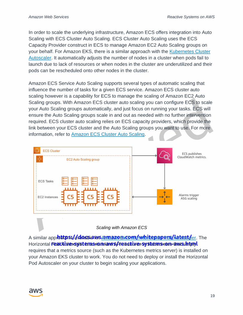
In order to scale the underlying infrastructure, Amazon ECS offers integration into Auto
Scaling with ECS Cluster Auto Scaling. ECS Cluster Auto Scaling uses the ECS
Capacity Provider construct in ECS to manage Amazon EC2 Auto Scaling groups on
your behalf. For Amazon EKS, there is a similar approach with the Kubernetes Cluster
Autoscaler. It automatically adjusts the number of nodes in a cluster when pods fail to
launch due to lack of resources or when nodes in the cluster are underutilized and their
pods can be rescheduled onto other nodes in the cluster.
Amazon ECS Service Auto Scaling supports several types of automatic scaling that
influence the number of tasks for a given ECS service. Amazon ECS cluster auto
scaling however is a capability for ECS to manage the scaling of Amazon EC2 Auto
Scaling groups. With Amazon ECS cluster auto scaling you can configure ECS to scale
your Auto Scaling groups automatically, and just focus on running your tasks. ECS will
ensure the Auto Scaling groups scale in and out as needed with no further intervention
required. ECS cluster auto scaling relies on ECS capacity providers, which provide the
link between your ECS cluster and the Auto Scaling groups you want to use. For more
information, refer to Amazon ECS Cluster Auto Scaling.
Scaling with Amazon ECS
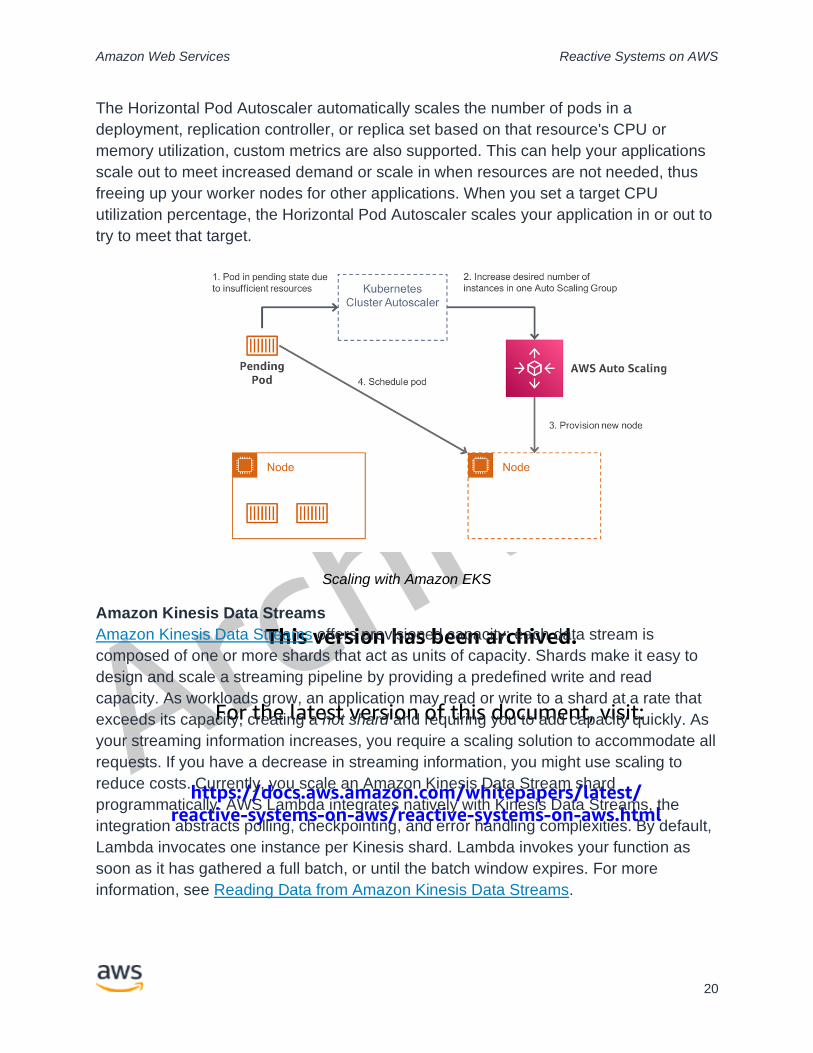
A similar approach is available for Amazon EKS with Horizontal Pod Autoscaler. The
Horizontal Pod Autoscaler is a standard API resource in Kubernetes that simply
requires that a metrics source (such as the Kubernetes metrics server) is installed on
your Amazon EKS cluster to work. You do not need to deploy or install the Horizontal
Pod Autoscaler on your cluster to begin scaling your applications.
This version has been archived.
For the latest version of this document, visit:
https://docs.aws.amazon.com/whitepapers/latest/reactive-systems-on-aws/reactive-systems-on-aws.html
Amazon Web Services Reactive Systems on AWS
20
The Horizontal Pod Autoscaler automatically scales the number of pods in a
deployment, replication controller, or replica set based on that resource's CPU or
memory utilization, custom metrics are also supported. This can help your applications
scale out to meet increased demand or scale in when resources are not needed, thus
freeing up your worker nodes for other applications. When you set a target CPU
utilization percentage, the Horizontal Pod Autoscaler scales your application in or out to
try to meet that target.
Scaling with Amazon EKS
Amazon Kinesis Data Streams
Amazon Kinesis Data Streams offers provisioned capacity: each data stream is
composed of one or more shards that act as units of capacity. Shards make it easy to
design and scale a streaming pipeline by providing a predefined write and read
capacity. As workloads grow, an application may read or write to a shard at a rate that
exceeds its capacity, creating a hot shard and requiring you to add capacity quickly. As
your streaming information increases, you require a scaling solution to accommodate all
requests. If you have a decrease in streaming information, you might use scaling to
reduce costs. Currently, you scale an Amazon Kinesis Data Stream shard
programmatically. AWS Lambda integrates natively with Kinesis Data Streams, the
integration abstracts polling, checkpointing, and error handling complexities. By default,
Lambda invocates one instance per Kinesis shard. Lambda invokes your function as
soon as it has gathered a full batch, or until the batch window expires. For more
information, see Reading Data from Amazon Kinesis Data Streams.
This version has been archived.
For the latest version of this document, visit:
https://docs.aws.amazon.com/whitepapers/latest/reactive-systems-on-aws/reactive-systems-on-aws.html
Amazon Web Services Reactive Systems on AWS
21
Message driven
A message-driven architecture uses messages to communicate between decoupled
services and is common in modern applications built with microservices, since
asynchronous message-passing between loosely coupled services helps to ensure
isolation and provides location transparency. The following section discusses different
messaging patterns and how these can be implemented on AWS.
Event sourcing and CQRS
In the context of microservices architectures, event sourcing decouples different parts of
an application by using a publish/subscribe pattern, and it feeds the same event data
into different data models for separate microservices. Event sourcing is frequently used
in conjunction with the Command Query Responsibility Segregation (CQRS) pattern to
decouple read from write workloads and optimize both for performance, scalability, and
security. Updates and queries are conventionally completed using a single datastore.
You can use CQRS to separate these two workloads if they have different access
patterns for throughput, latency, or consistency. When you separate command and
query functions, you can scale them independently.
AWS messaging services
AWS messaging services enable different software systems and end devices - often
using different programming languages, and on different platforms - to communicate
and exchange information. Amazon Kinesis Data Streams is a scalable and durable
real-time data streaming service. A data stream is a logical grouping of shards, each
shard is an append-only log and a unit of streaming capability. It contains an ordered
sequence of records ordered by arrival time. In the example architecture Kinesis Data
Streams is used to decouple services. Another option would be to use Amazon
Managed Streaming for Apache Kafka (Amazon MSK), a fully-managed service that
enables you to build and run applications that use Apache Kafka to process streaming
data. Amazon MSK provides the control-plane operations, such as those for creating,
updating, and deleting clusters. It lets you use Apache Kafka data-plane operations,
such as those for producing and consuming data. One of the major advantages of
services like Kinesis Data Streams or Amazon MSK is the ability to replay events within
a defined retention period.
A different pattern is publish/subscribe (pub/sub) messaging. It is a form of
asynchronous service-to-service communication used in serverless and microservices
architectures. In a pub/sub model, any message published to a topic is immediately
received by all of the subscribers to the topic. Amazon SNS is a fully managed pub/sub
messaging service that enables message delivery to millions of subscribers. Amazon
SQS is a message queue service used by distributed applications to exchange
This version has been archived.
For the latest version of this document, visit:
https://docs.aws.amazon.com/whitepapers/latest/reactive-systems-on-aws/reactive-systems-on-aws.html
Amazon Web Services Reactive Systems on AWS
22
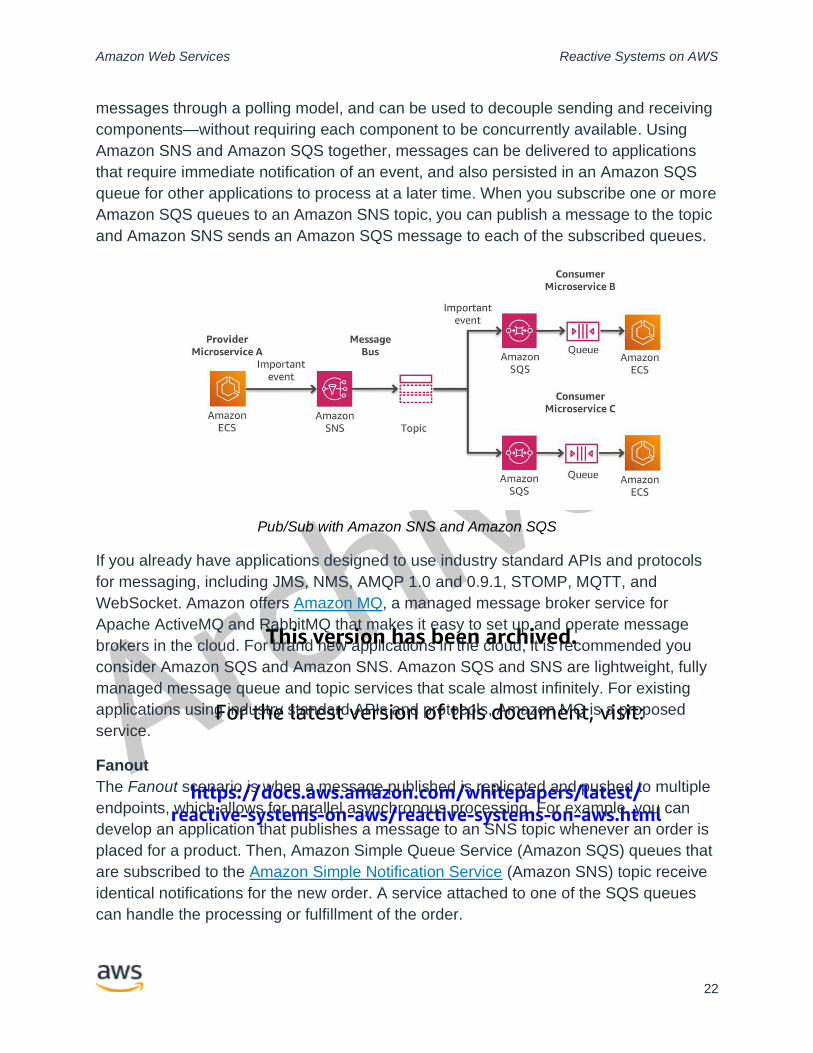
messages through a polling model, and can be used to decouple sending and receiving
components—without requiring each component to be concurrently available. Using
Amazon SNS and Amazon SQS together, messages can be delivered to applications
that require immediate notification of an event, and also persisted in an Amazon SQS
queue for other applications to process at a later time. When you subscribe one or more
Amazon SQS queues to an Amazon SNS topic, you can publish a message to the topic
and Amazon SNS sends an Amazon SQS message to each of the subscribed queues.
Pub/Sub with Amazon SNS and Amazon SQS
If you already have applications designed to use industry standard APIs and protocols
for messaging, including JMS, NMS, AMQP 1.0 and 0.9.1, STOMP, MQTT, and
WebSocket. Amazon offers Amazon MQ, a managed message broker service for
Apache ActiveMQ and RabbitMQ that makes it easy to set up and operate message
brokers in the cloud. For brand new applications in the cloud, it is recommended you
consider Amazon SQS and Amazon SNS. Amazon SQS and SNS are lightweight, fully
managed message queue and topic services that scale almost infinitely. For existing
applications using industry standard APIs and protocols, Amazon MQ is a proposed
service.
Fanout
The Fanout scenario is when a message published is replicated and pushed to multiple
endpoints, which allows for parallel asynchronous processing. For example, you can
develop an application that publishes a message to an SNS topic whenever an order is
placed for a product. Then, Amazon Simple Queue Service (Amazon SQS) queues that
are subscribed to the Amazon Simple Notification Service (Amazon SNS) topic receive
identical notifications for the new order. A service attached to one of the SQS queues
can handle the processing or fulfillment of the order.
This version has been archived.
For the latest version of this document, visit:
https://docs.aws.amazon.com/whitepapers/latest/reactive-systems-on-aws/reactive-systems-on-aws.html
Amazon Web Services Reactive Systems on AWS
23
Filtering
By default, an Amazon SNS topic subscriber receives every message published to the
topic. To receive a subset of the messages, a subscriber must assign a filter policy to
the topic subscription. A filter policy is a simple JSON object containing attributes that
define which messages the subscriber receives. When you publish a message to a
topic, Amazon SNS compares the message attributes to the attributes in the filter policy
for each of the topic's subscriptions. If any of the attributes match, Amazon SNS sends
the message to the subscriber. Otherwise, Amazon SNS skips the subscriber without
sending the message.
Conclusion
After reviewing the concepts for reactive systems, you should have a good
understanding of the landscape of potential AWS services you can choose to build a
reactive system on AWS.
The key patterns in this paper, highlighted the necessary concepts for implementing the
foundational building block for reactive systems. The characteristics of reactive systems
based on the definition of the reactive manifesto.
The example architecture utilizes the same patterns on a micro-level which are being
used on an architectural macro-level. The AWS services are a great starting point to
implement reactive principles and microservices improve isolation of different
workloads. In combination with managed services, you can focus on the business
requirements and remove the undifferentiated heavy lifting.
Contributors
Contributors to this document include:
• Sascha Möllering, Senior Specialist Solutions Architect for Containers, Amazon
Web Services
• Michael Hanisch, DACH Head of Technology, Amazon Web Services
This version has been archived.
For the latest version of this document, visit:
https://docs.aws.amazon.com/whitepapers/latest/reactive-systems-on-aws/reactive-systems-on-aws.html
Amazon Web Services Reactive Systems on AWS
24
Further reading
For additional information, refer to:
• Implementing Microservices on AWS
• Database Caching Strategies Using Redis
• Performance at Scale with Amazon ElastiCache
Document revisions
Date Description
November 1, 2021 First publication
Notes
1 K. Mani Chandy Event-Driven Applications: Costs, Benefits and Design Approaches,
California Institute of Technology, 2006