Embed Size (px)
Citation preview

Subscriber access provided by Univ. of Texas Libraries
Journal of the American Chemical Society is published by the American ChemicalSociety. 1155 Sixteenth Street N.W., Washington, DC 20036
Scanning tunneling microscopy studies of carbon-oxygenreactions on highly oriented pyrolytic graphite
Hsiangpin Chang, and Allen J. BardJ. Am. Chem. Soc., 1991, 113 (15), 5588-5596 • DOI: 10.1021/ja00015a012
Downloaded from http://pubs.acs.org on January 23, 2009
More About This Article
The permalink http://dx.doi.org/10.1021/ja00015a012 provides access to:
• Links to articles and content related to this article• Copyright permission to reproduce figures and/or text from this article
5588
with the features of */A isotherms, and with the temperature dependence of the isotherms. An unusual surface phase transition is observed for this material, where AS,,,,, > 0; a model of this process has been presented ('starfish +.jellyfish" transition) and involves the transformation of 2D radial surface micelles into quasi-2D aggregates with the poorly water-soluble polyelectrolyte chains being submerged in the aqueous subphase.
J . Am. Chem. SOC. 1991, 113, 5588-5596
Acknowledgment. We thank NSERC Canada (R.B.L., A.E.), the US. Army Research Office (J.Z., A.E.), and the McGill Graduate Faculty (R.B.L.) for financial support of this research. R.B.L. thanks D. A. Cadenhead for helpful discussions, and we thank M. Harrigan, McGill Department of Occupational Health, for providing us with assistance with the electron microscope experiments.
Scanning Tunneling Microscopy Studies of Carbon-Oxygen Reactions on Highly Oriented Pyrolytic Graphite
Hsiangpin Chang? and Allen J. Bard*
Contribution from the Department of Chemistry, The University of Texas at Austin, Austin, Texas 78712. Received February 26, 1991
Abstract The oxidation of highly oriented pyrolytic graphite (HOPG) in air at elevated temperatures was studied by examination of the oxidized HOPG by scanning tunneling microscopy (STM). Etch pits of uniform size and monolayer depth were readily formed on preexisting defects or generated vacancies in the HOPG basal plane by heating freshly cleaved HOPG samples in air at 650 OC. The density of the pits in different samples of H O E varied from 0.1 to 13 pm-2. When the oxidized HOPG samples were reheated and reexamined by STM, the original etch pits had grown and new, smaller etch pits were found. Therefore, pit growth initiation occurred during each cooling-reheating cycle, and consecutive heating cycles could control the pit density. At higher temperatures, above 700 'C, carbon abstraction occurred on the basal plane of graphite, which generated additional vacancies and initiated new etch pits continuously throughout the period of heating at this temperature. The rates of carbon abstraction in both cases depended on the vacancy-density of the HOPG. On HOPG samples treated with different materials, both those expected to be chemically active (e.g., FeCI3, CdS, H2PtCI6) or inert (e.g., NaCI, AI2O3), numerous etch channels were found on the surfaces after oxidation, representing the paths of randomly moving particles. Because similar channels are formed with all of these materials, these channels are probably mainly produced by mechanical interactions by the particles on the graphite surface.
Introduction Recently we reported the formation of monolayer etch pits on
HOPG by gasification reactions with dioxygen as imaged and studied by STM.' These etch pits were reproducibly formed across the entire surface of a freshly cleaved HOPG sample, and their size (5-400 nm) increased linearly with reaction time. Several applications of these etch pits were proposed. For example, they could be useful as markers and molecular containers for STM imaging, and may behave as active sites of controlled density for chemical and electrochemical reactions. We report here more detailed STM studies of the oxidation (gasification) of HOPG in air, including studies in which various species were added to the HOPG surface. Such studies provide some insight into the early stages of graphite gasification. Moreover, we felt that a better understanding of the factors that govern formation of the etch pits would lead to better control of their shape, size, and density.
There have been extensive studies of gasification reactions of carbon, especially graphite, in pioneering work by Hennig, Thomas, Yang, and others2" using microscopic techniques, in- cluding optical microscopy, scanning electron microscopy (SEM), and etch-decoration transmission electron microscopy (ED-TEM). A particular advantage of microscopic studies of graphite oxi- dation, compared, for example, to weight loss or product yield measurements, is that it is possible, in favorable circumstances, to distinguish sites of different reactivity on the carbon surface.2c It is clear that carbon surfaces (and probably the surfaces of most other substances) are heterogeneous and that, in many cases, reactions occur at much higher rates at certain sites, e.g., lattice defects or impurity sites. Microscopic methods in general, and as we show here, STM in particular can provide information about
'Current address: Westhollow Research Center, Shell Development Co., Houston, TX 77082.
0002-786319111513-5588%02.50/0
site reactivity in carbon gasification, which is of interest in con- nection with many important processes, e.g., combustion and water gas prod~ct ion.~ A great deal of information has been obtained, including surface images with near atomic resolution, with ED- TEM,2,4v5 invented by Henning and later used by Thomas, Yang, and others. The mechanism of the C-O2 reaction is tempera- ture-dependent. At temperatures below 700 OC, the carbon- oxygen reaction is highly dependent on the nature of the carbon sites on the HOPG; oxidation is initiated mainly at defects, va- cancies, or edge atoms along cleavage steps, presumably because of their unoccupied sp2 orbitals. At temperatures above 700 "C,
( I ) Chang, H.; Bard, A. J. J . Am. Chem. SOC. 1990, 112, 4598. (2) (a) Yang, R. T. In Chemistry and Physics of Carbon; Walker, P. L.,
Jr., Thrower, P. A., Eds.; Marcel Dekker: New York, 1984; Vol. 19, pp 163-210. (b) Hennig, G. R. Ibid.; Walker, P. L., Ed.; 1966; Vol. 2, pp 1-50. (c) Thomas, J. M. Ibid.; Walker, P. L., Ed.; Marcel Dekker: New York, 1965, Vol. I , pp 121-203. (d) Walker, R. T. K. Catal. Rev.-Sci. Eng. 1979.19, 161.
(3) (a) Kinoshita, K. Carbon: Electrochemical and Physical Properties; Wiley: New York, 1988; Chapter 4. (b) Strange, J . F.; Walker, P. L., Jr. Carbon 1976, 14, 345. (c) Rodriguez-Reinoso, F.; Thrower, P. A. Ibid. 1974, 12, 269. (d) KcKee, D. W. Ibid. 1970,8, 623. (f) Laine, N. R.; Vastola, F. J.; Walker, P. L. J . Phys. Chem. 1963, 67, 2030. (e) Bonner, F.; Turkevich, J. J . Am. Chem. SOC. 1951, 73, 561. (f) Lewis, W. K.; Gilliland, E. R.; McBride, G. T., Jr. Ind. Eng. Chem. 1949, 41, 1213.
(4) (a) Yang, K. L.; Yang, R. T. AIChEJ. 1985,31, 1313. (b) Yang, R. T.; Yang, K. L. Carbon 1985,23,537. (c) Duan, R.-Z.; Yang, R. T. Chem. Eng. Sei. 1984, 39, 795. (d) Yang, R. T.; Wong, C. J . Catal. 1984,85, 154. (e) Yang, R. T.; Wong, C. Science 1981, 214,437. (f) Yang, R. T.; Wong, C. AIChE J. 1983, 29, 338. (g) Wong, C.; Yang, R. T.; Halpern, B. L. J . Chem. Phys. 1983, 78, 3325. (h) Wang, R. T.; Wong, C. Ind. Eng. Chem. Fundam. 1983,22, 380. (i) Yang, R. T.; Wong, C. Rev. Sei. Insrrum. 1982, 53, 1488. (j) Yang, R. T.; Wong, C. J . Chem. Phys. 1981, 75.4471. (k) Wong, C. Ph.D. Thesis, SUNY-Buffalo, Amherst, NY, 1983. ( I ) Cen, P.; Yang, R. T. Carbon 1984, 22, 186.
( 5 ) (a) Hennig, G. R. J. Chem. Phys. 1964,40, 2877. (b) Hennig, G. R. J. Inorg. Nucl. Chem. 1962, 24, 1129. (c) Evans, E. L.; Griffiths, R. J. M.; Thomas, J. M. Science 1970, 171, 174. (d) Fates, F. S. Trans. Faraday Soc. 1968, 64, 3093. (e) Montet, G. L.; Myers, G. E. Carbon 1968, 6, 627.
0 1991 American Chemical Society
Carbon-Oxygen Reactions on Pyrolytic Graphite
in addition to the above sites, oxygen can attack and abstract carbon atoms from the basal plane atoms of graphite and initiate new vacancies. Upon oxidation, these vacancies expand to form monolayer etch pits. In ED-TEM, these etch pits are imaged by electron microscopy after decoration with gold or other metals, which are evaporated onto the graphite surface where metal particles nucleate on the edges of etch pits and steps.
While ED-TEM has provided useful images of oxidized graphite surfaces, it cannot provide the topographic resolution of STM nor has it been used to study the very early stages of the process. Moreover, decoration of the surface with evaporated gold is complicated and cannot be employed with multiple oxidation experiments on the same graphite sample, as described in this paper. Successive heating steps combined with STM examination can yield information concerning the mechanism of pit formation. We show here that STM6 is a useful technique for the study of the early stages of the gasification reaction. Its main advantages lie in its high resolution and ability to image the etch pits without prior modification.
Experimental Section A Nanoscope I1 STM (Digital Instruments, Santa Barbara, CA) was
used. Pt-Ir (80:20) microtips (Digital Instruments) were used following electrochemical etching.' Slightly damaged tips were regenerated by reetching for a short time. Although the images usually did not change with imaging parameters, including bias voltage (A900 mV), set point current (0.6-2 nA), and scan rate (2-8 Hz), relatively high gap resist- ances (Le., bias voltage/set point current) and slow scan rates were favored to minimize tip-sample interaction. The following set of pa- rameters are typical: bias voltage, 900 mV; set point current, 0.61 nA; scan rate, 2 Hz. Most of the images were obtained in the height image (constant current) mode; however, the current image mode was also occasionally used for comparison. Images are shown without filtering, except for some large-scale images, which were flattened (i.e., digitally treated to remove tilt in the sample relative to the tip-scanning plane), and for the surface view image (Figure 1 b), which was lowpass filtered.
A three-chamber tube furnace (Lindberg Model 59744, Watertown, WI) was used for heating. In an earlier study,' the sample was placed at the bottom of a porcelain crucible, which positioned the sample close to the bottom of the furnace. In this study, the sample was placed on a porcelain crucible lid, which was put on a quartz support so that the sample was near the center of the furnace tube and the thermocouple. Heating was started by directly inserting the lid with sample into the furnace preheated to the desired temperature, and was stopped by withdrawing it from the furnace into the air, unless otherwise indicated. When a controlled atmosphere was used, a quartz tube (2 cm in diameter by 100 cm in length) was placed at the center of the furnace. The flowing gas passed through two preheating zones before entering the reaction zone where the samples were placed directly in the tube. I n this case, samples were cooled by a fast flow of either air or argon.
HOPG8 samples were generously supplied by Dr. Arthur W. Moore of Union Carbide Corporation, Parma, OH. These samples consisted of several grades with some differences in physical appearances, e.g., grain size. This probably accounts for the observed differences in behavior described below. The HOPG samples were freshly cleaved with sticky tape immediately before heating, unless otherwise indicated. When particulate materials were used to coat the HOPG, a 1% (w:v) solution or slurry of these materials was used to dip coat the HOPG samples. Spin coating was used for Nafion-coated samples. The coated samples were air-dried in a covered vessel for at least 3 h before heating. Nafion solution was obtained from Aldrich (Milwaukee, WI) and alumina powder (Alz03, 0.3 pm) from Buehler (Lake Bluff, IL). All other chemicals were reagent grade.
Results and Discussion Oxidation of Untreated Graphite Surfaces. The Size, Shape,
and Density of Etch Pits Formed by Air Oxidation at 650 OC. At
(6) (a) Binnig, G.; Rohrer, H. Helu. Phys. Acta 1982,55,726. (b) Binnig, G.; Rohrer, H.; Gerber, Ch.; Weibel, E. Phys. Rev. Lett. 1982, 49, 57. (c) Binnig, G.; Rohrer, H. IBM J . Res. Deu. 1986, 30, 355. (d) Hansma, P.; Tersoff, J. J. Appl. Phys. 1987, 61, R1. (e) Albrecht, T. R.; Mizes, H. A.; Nogami, J.; Park, S.-l.; Quate, C. F. Appl. Phys. Lett. 1989, 52, 362.
(7) Gewirth, A. A.; Craston, D. H.; Bard, A. J. J. Electroanal. Chem. Interfacial Electrochem. 1989, 261, 477.
(8) (a) Moore, A. W. In Chemistry and Physics of Carbon; Walker, P. L., Jr., Thrower, P. A., Eds.; Marcel Dekker: New York, 1973; Vol. 11, pp 69-187. (b) Moore, A. W. Ibid.; Walker, P. L., Jr., Thrower, P. A., Eds.; Marcel Dekker: New York, 1981; Vol. 17, pp 233-287.
J . Am. Chem. SOC., Vol. 113, No. 15, 1991 5589
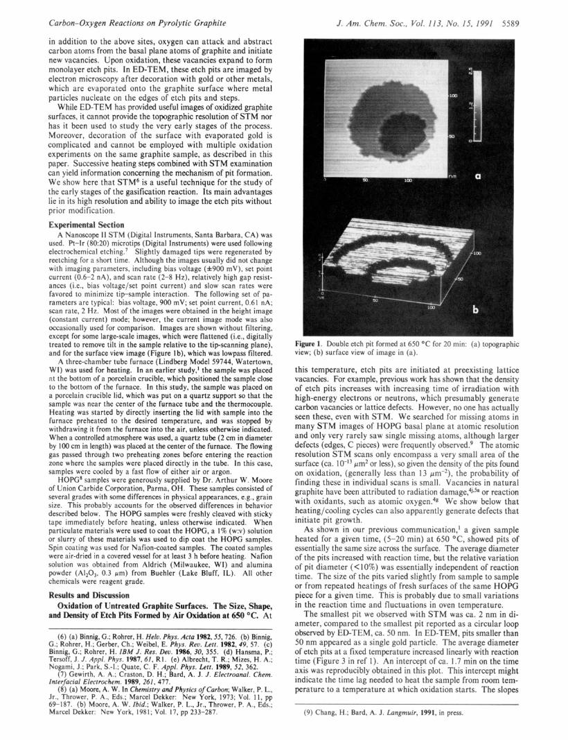
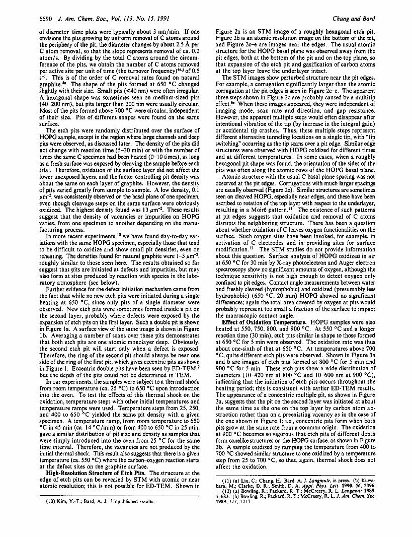
Figure 1. Double etch pit formed at 650 "C for 20 min: (a) topographic view; (b) surface view of image in (a).
this temperature, etch pits are initiated at preexisting lattice vacancies. For example, previous work has shown that the density of etch pits increases with increasing time of irradiation with high-energy electrons or neutrons, which presumably generate carbon vacancies or lattice defects. However, no one has actually seen these, even with STM. We searched for missing atoms in many STM images of HOPG basal plane at atomic resolution and only very rarely saw single missing atoms, although larger defects (edges, C pieces) were frequently ~bserved.~ The atomic resolution STM scans only encompass a very small area of the surface (ca. 1 @ I 3 pm2 or less), so given the density of the pits found on oxidation, (generally less than 13 pm-2), the probability of finding these in individual scans is small. Vacancies in natural graphite have been attributed to radiation damage?jlsa or reaction with oxidants, such as atomic ~xygen.~g We show below that heating/cooling cycles can also apparently generate defects that initiate pit growth.
As shown in our previous communication,' a given sample heated for a given time, (5-20 min) at 650 OC, showed pits of essentially the same size across the surface. The average diameter of the pits increased with reaction time, but the relative variation of pit diameter (< 10%) was essentially independent of reaction time. The size of the pits varied slightly from sample to sample or from repeated heatings of fresh surfaces of the same HOPG piece for a given time. This is probably due to small variations in the reaction time and fluctuations in oven temperature.
The smallest pit we observed with STM was ca. 2 nm in di- ameter, compared to the smallest pit reported as a circular loop observed by ED-TEM, ca. 50 nm. In ED-TEM, pits smaller than 50 nm appeared as a single gold particle. The average diameter of etch pits at a fixed temperature increased linearly with reaction time (Figure 3 in ref 1). An intercept of ca. 1.7 min on the time axis was reproducibly obtained in this plot. This intercept might indicate the time lag needed to heat the sample from room tem- perature to a temperature at which oxidation starts. The slopes
(9) Chang, H.; Bard, A. J. Langmuir, 1991, in press.
5590 J . Am. Chem. Soc., Vol. 113, No. 15, 1991 Chang and Bard
Figure 2a is an STM image of a roughly hexagonal etch pit. Figure 2b is an atomic resolution image on the bottom of the pit, and Figure 2c-e are images near the edges. The usual atomic structure for the HOPG basal plane was observed away from the pit edges, both at the bottom of the pit and on the top plane, so that expansion of the etch pit and gasification of carbon atoms at the top layer leave the underlayer intact.
The STM images show perturbed structure near the pit edges. For example, a corrugation significantly larger than the atomic corrugation at the pit edges is seen in Figure 2c-e. The apparent three steps shown in Figure 2c are probably caused by a multitip effect." When these images appeared, they were independent of imaging mode, scan rate and direction, and gap resistance. However, the apparent multiple steps would often disappear after intentional vibration of the tip (by increase in the integral gain) or accidental tip crashes. Thus, these multiple steps represent different alternative tunneling locations on a single tip, with "tip switching" occurring as the tip scans over a pit edge. Similar edge structures were observed with HOPG oxidized for different times and at different temperatures. In some cases, when a roughly hexagonal pit shape was found, the orientation of the sides of the pits was often along the atomic rows of the HOPG basal plane.
Atomic structure with the usual C basal plane spacing was not observed at the pit edges. Corrugations with much larger spacings are usually observed (Figure 2e). Similar structures are sometimes Seen on cleaved HOPG, especially near edges, and these have been ascribed to rotation of the top layer with respect to the underlayer, resulting in a Moirt pattern." The existence of such patterns at pit edges suggests that oxidation and removal of C atoms disrupts the neighboring structure. There has been a question about whether oxidation of C leaves oxygen functionalities on the surface. Such oxygen sites have been invoked, for example, in activation of C electrodes and in providing sites for surface modification.I2 The STM studies do not provide information about this question. Surface analysis of HOPG oxidized in air at 650 OC for 30 min by X-ray photoelectron and Auger electron spectroscopy show no significant amounts of oxygen, although the technique sensitivity is not high enough to detect oxygen only confined to pit edges. Contact angle measurements between water and freshly cleaved (hydrophobic) and oxidized (presumably less hydrophobic) (650 OC, 20 min) HOPG showed no significant differences; again the total area covered by oxygen at pits would probably represent too small a fraction of the surface to impact the macroscopic contact angle.
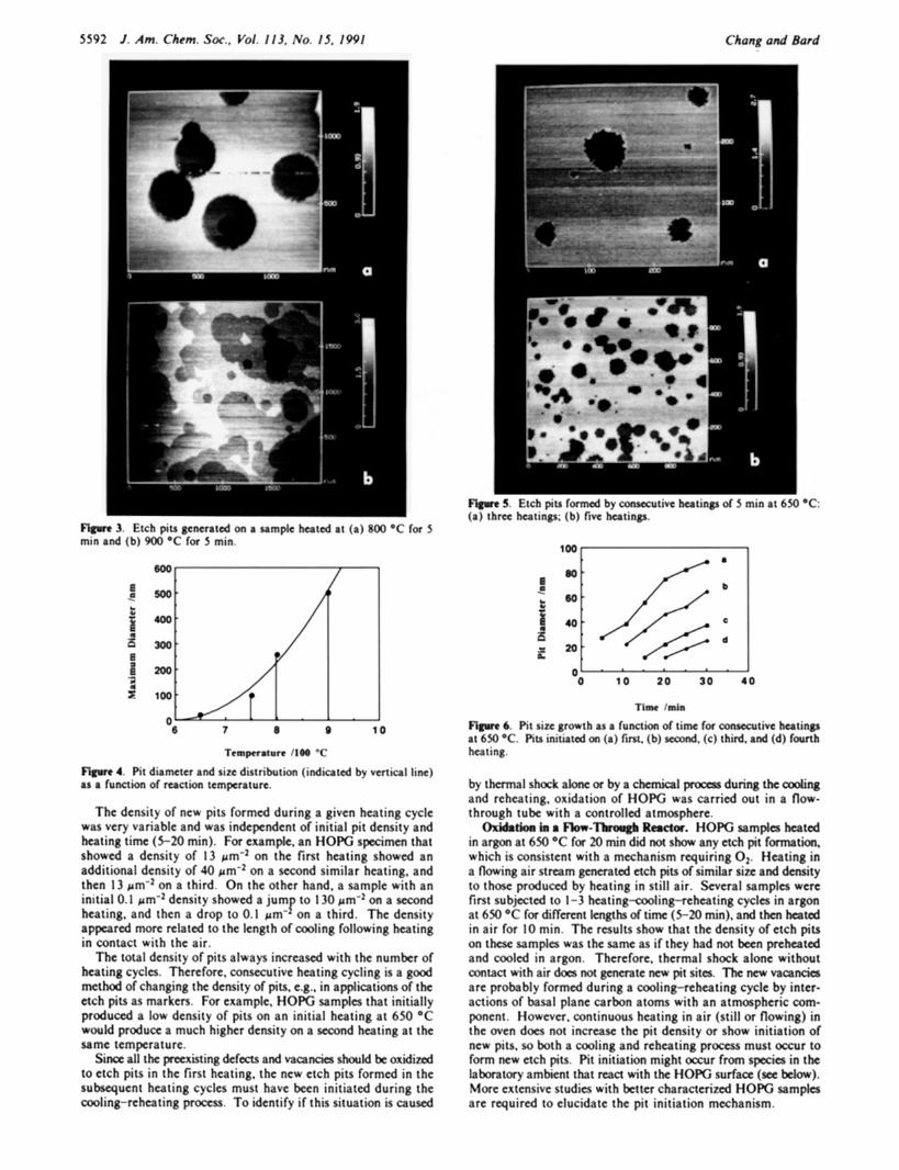
Effect of Oxidation Temperature. HOPG samples were also heated at 550, 750, 800, and 900 O C . At 550 OC and a longer reaction time (30 min), etch pits similar in shape to those formed at 650 OC for 5 min were observed. The oxidation rate was thus about one-sixth of that at 650 O C . At temperatures above 700 OC, quite different etch pits were observed. Shown in Figure 3a and b are images of etch pits formed at 800 OC for 5 min and 900 OC for 5 min. These etch pits show a wide distribution of diameters (10-420 nm at 800 OC and 10-600 nm at 900 "C), indicating that the initiation of etch pits occurs throughout the heating period; this is consistent with earlier ED-TEM results. The appearance of a concentric multiple pit, as shown in Figure 3a, suggests that the pit on the second layer was initiated at about the same time as the one on the top layer by carbon atom ab- straction rather than on a preexisting vacancy as in the case of the one shown in Figure 1; Le., concentric pits form when both pits grow at the same rate from a common origin. The oxidation at 900 O C becomes so vigorous that etch pits of different depth form conelike structures on the HOPG surface, as shown in Figure 3b. A sample oxidized by ramping the temperature from 400 to 700 O C showed similar structure to one oxidized by a temperature step from 25 to 700 OC, so that, again, thermal shock does not affect the oxidation.
( 1 1) (a) Liu, C.; Chang, H.; Bard, A. J. Lungmuir, in press. (b) Kuwa- bara, M.; Clarke, D. R.; Smith, D. A. Appl. Phys. Lerr. 1990, S6, 2396.
( 1 2) (a) Bowling, R.; Packard, R. T.; McCrcery, R. L. Lungmuir 1989, 5,683. (b) Bowling, R.; Packard, R. T.; McCreery, R. L. J . Am. Chem. Soc. 1989, I l l , 1217.
of diameter-time plots were typically about 3 nm/min. If one envisions the pits growing by uniform removal of C atoms around the periphery of the pit, the diameter changes by about 2.5 A per C atom removal, so that the slope represents removal of ca. 0.2 atom/s. By dividing by the total C atoms around the circum- ference of the pits, we obtain the number of C atoms removed per active site per unit of time (the turnover frequency)&J of 0.5 s-I. This is of the order of C removal rates found on natural graphite.4a The shape of the pits formed a t 650 OC changed slightly with their size. Small pits (C40 nm) were often irregular. A hexagonal shape was sometimes seen on medium-sized pits (40-200 nm), but pits larger than 200 nm were usually circular. Most of the pits formed above 700 OC were circular, independent of their size. Pits of different shapes were found on the same surface.
The etch pits were randomly distributed over the surface of HOPG sample, except in the region where large channels and deep pits were observed, as discussed later. The density of the pits did not change with reaction time (5-30 min) or with the number of times the same C specimen had been heated (0-10 times), as long as a fresh surface was exposed by cleaving the sample before each trial. Therefore, oxidation of the surface layer did not affect the lower unexposed layers, and the factor controlling pit density was about the same on each layer of graphite. However, the density of pits varied greatly from sample to sample. A low density, 0.1 pm-2, was consistently observed on the basal plane of one specimen, even though cleavage steps on the same surface were obviously oxidized. The highest density found was 13 pm-2. These results suggest that the density of vacancies or impurities on HOPG varies, from one specimen to another depending on the manu- facturing process.
In more recent experiments,I0 we have found day-to-day var- iations with the same HOPG specimen, especially those that tend to be difficult to oxidize and show small pit densities, even on reheating. The densities found for natural graphite were 1-5 pm-2, roughly similar to those seen here. The results obtained so far suggest that pits are initiated at defects and impurities, but may also form at sites produced by reaction with species in the labo- ratory atmosphere (see below).
Further evidence for the defect initiation mechanism came from the fact that while no new etch pits were initiated during a single heating at 650 O C , since only pits of a single diameter were observed. New etch pits were sometimes formed inside a pit on the second layer, probably where defects were exposed by the expansion of etch pits on the first layer. Such a double pit is shown in Figure la. A surface view of the same image is shown in Figure lb. Averaging a number of scans over these pits demonstrates that both etch pits are one atomic monolayer deep. Obviously, the second etch pit will start only when a defect is exposed. Therefore, the ring of the second pit should always be near one side of the ring of the first pit, which gives eccentric pits as shown in Figure 1. Eccentric double pits have been seen by ED-TEM,2 but the depth of the pits could not be determined in TEM.
In our experiments, the samples were subject to a thermal shock from room temperature (ca. 25 "C) to 650 OC upon introduction into the oven. To test the effects of this thermal shock on the oxidation, temperature steps with other initial temperatures and temperature ramps were used. Temperature steps from 25,250, and 400 to 650 O C yielded the same pit density with a given specimen. A temperature ramp, from room temperature to 650 OC in 45 min (ca. 14 OC/min) or from 400 to 650 OC in 25 min, gave a similar distribution of pit size and density as samples that were simply introduced into the oven from 25 O C for the same time interval. Therefore, the vacancies are not produced by the initial thermal shock. This result also suggests that there is a given temperature (ca. 550 "C) where the carbon-oxygen reaction starts at the defect sites on the graphite surface.
High-Resolution Structure of Etch Pits. The structure at the edge of etch pits can be revealed by STM with atomic or near atomic resolution; this is not possible for ED-TEM. Shown in
(10) Kim, Y.-T.; Bard, A. J. Unpublished results.
Carban-Oxyl(m Reactfons on Pyrafytic Graphfte J . Am. Chem. Sac.. Vol. I l f . No. I S . IWI 3391
2. ( 8 ) Etch pir (b l Aromic %lruciurc at thc bottom of rhc pir in f a ) . fc ) . fd). ( c ) Srrucrurc near rhc c d ~ c in ( a ) .
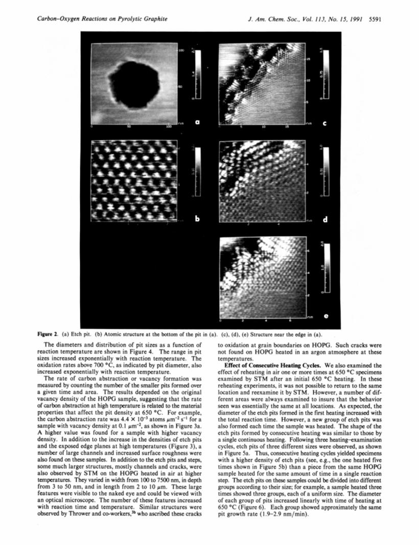
The diameters and distribution of pit sixes as a function of reaction temperature are shown in figure 4. The range in pit sixes increased exponentially with reaction tempcraturc. The oxidation ratm a h c 700 OC. as indicated by pit diameter, also increased exponentially with reaction tcmpcmturc.
Thc rate of carbon abstraction or vacancy formation was m s u r e d by counting thc numbcr of the smllcr pits f o m d over a given time and arm. The results dcpcndcd on the original vacancy density of the HOPG sample. suggesting that thc rate of c a r h a b t n c t i m at high temperature is related to the miterial propcrties that affcct thc pit dcnsity at 650 "C. For examplc, the carbon abstraction ratc was 4.4 X 10" atoms pm'2 s-' for a sample with vacancy density at 0.1 pm-z, as shown in Figure 3a. A higher value was found for a sample with higher vacancy density. In addition to thc increase in the densities of etch pits and the expotcd edge planes at high tempcraturcs (Figure 3) , a numbcr of larpc channels and incrcascd surface rooghncss were aLw found on t h e e simples. In addition to t h e etch pts and l n c p t some much largcr structures, mostly channels and cracks, wcre also observed by STM on the €IO€% heatcd in air at higher tempmtum. They vaned in width from IO to 7500 nm, in dcph from 3 to 50 nm, and in length from 2 to 10 pm. Thesc lnrpc fa tures were visible to the naked c y and could be vicwcd with an optical microscope. The number of these fca tum increa.4 with reaction timc and tcmpcrature. Similar structures wcre obtcrved by Thrower and co-workm.B who a-scribcd thcsc mckt
to oxidation at grain boundaries on HOW. Such cracks were not found on HOW heated in an argon atmosphere at thest tempcratum.
E f k t of Caawcr(ivt Heating Cydes. We also examined the effcct of rchatinp in air onc or more t i m at 650 "C spccimms cxamincd by STV after an initial 650 "C heating. In these rchcating expcrimcnts, it was not passible to retum to the same location and rctxamine it by STW. Ifowever, a number of dif- fcrcnt arcas wcrc always cxamincd to insure that the behavior seen was csscntially the same at all locations. As expected, the diametcr of the etch pits f& in the first hat ing i m . 4 with thc total reaction timc. Howcvcr, a new group of etch pits was alca formcd a c h timc thc Limple was hated. The shapc of the ctch pits formed by consccutivc ha t ing was similar to t h by 8 sinplc continuous hating. Following t h m htinp-txaminatim cycln, etch pits of thrct diffcrcnt sites wcre obwrved. as shown in F'igurc 5a. Thus. " a x t i v c k i t i n g cycles yicldcd s p m m with a higher density of etch pits (scc. e.g.. thc onc heated five t i m e shown in Figure Sb) than a piccc from the samc €IOPG sample hcarcd for the same amaunt of time in a single miction stcp. The etch pits on t k samplcz could bc divided into d i f f m t group according to their site; for example. a simple heated th ree times showcd t h r t c group, mch of a uniform sirc. Thc diameter of cach group of pits incrawd lincarly with time of heating at 650 OC' (!?pure 6). Lich group showed approximately the mme pit growth rate (1.9-2.0 nm/min).
5592 J. Am. Chem. Sac., Vol. 113, No. I S . I 9 9 1 Chang a d Bard
Flgwe 5. Etch pru formed by msccutivc heating of 5 mrn at 63-0 .C (a) three hatinpir; (b) five h,crtinps.
Flawre 3. Etch pits g e m t a d on a sample heated at (a) R O O "C for 3 mtn and (b) oloo "C for 3 min.
The density of new pits formed during a given heating cycle was very variable and was independent of initial pit density and heating time (5-20 min). For example, an HOPG sptcimm that showed a density of 13 pm-2 on the fint heating showed an additional density of 40 pm-* on a second similar heating, and then 13 pm-* on a third. On the other hand. a sample with an initial 0.1 pm*z density showed a jump to 130 pmmZ on a second heating, and then a drop to 0.1 pm'- on a third. The density appeared more related to the length of cooling following heating in contact with the air.
The total density of pits always incttascd with the number of heating cycles. Therefore. comxutive heating cycling is a good method of changing the density of pits, e.g., in applications of the etch pits as marken. For example, HOPG samples that initially produced a low density of pits on an initial heating at 650 OC would produce a much higher density on a second heating at the same tcmpcratutc.
Si- all tbc paxisting <kfaaS and vacandor shouM be oxidized to etch pits in the first heating, the new etch pits formed in the subsequent heating cycles must have been initiated during the cooling-reheating proces.5. To identify if this situation is caused
0- 0 10 20 30 4 0
tiw Imh
6. Pit sire @mth 8s a functh of time for c " t h h a t i n g at 650 "C. Pits initiatcd on ((I) fim. (b) sdo(Md. (c) third. and (d) fourth heating.
by thmnal s b c k a h or by a ehunical po#ss during the d n g and reheating, oxidation of H O E was carried out in a flow- through tube with a controlled atmosphere.
0x)Ctrtbcl bs 8 Ra(rr-Thwgb R e a r . HOPG samples heated in argon at 650 "C for 20 min did not s h any etch pit f m t i o n , which is consistent with a mechanism requiring 02. Heating in a flowing air stteam generated etch pits of similar sine and density to those p r o d u d by heating in still air. Several samples were first subjected to 1-3 h e a t i n g w l i n g r e k t i n g cycles in argon at 630 "C for diffirmt lengths of time (5-20 min), and then heated in air for 10 min. The results show that the dcnsity of etch pits on t k samples was the same as if they had not been preheated and cooled in argon. Therefore, thermal shock alone without amtact with air dcm not gemrate new pit sites. The new vacancies are probably formed during a cooling-reheating cycle by inter- actions of basal plane carbon atoms with an atmospheric com- ponent. Howcver, continuous heating in air (still or flowing) in the Oven does not increase the pit density or show initiation of new pits, 50 both a cooling and reheating process must occur to form new etch pits. Pit initiation might occur from species in the laboratory ambient that mct with the HOPG surface (see belw). Morc extensive studies with better characterized HOPG samples are required to elucidate the pit initiation mechanism.
Carbon-Oxygen Reactions on Pyrolytic Graphite J . Am. Chem. Soc., Vol. 113, No. 15, 1991 5593
600 nm
a
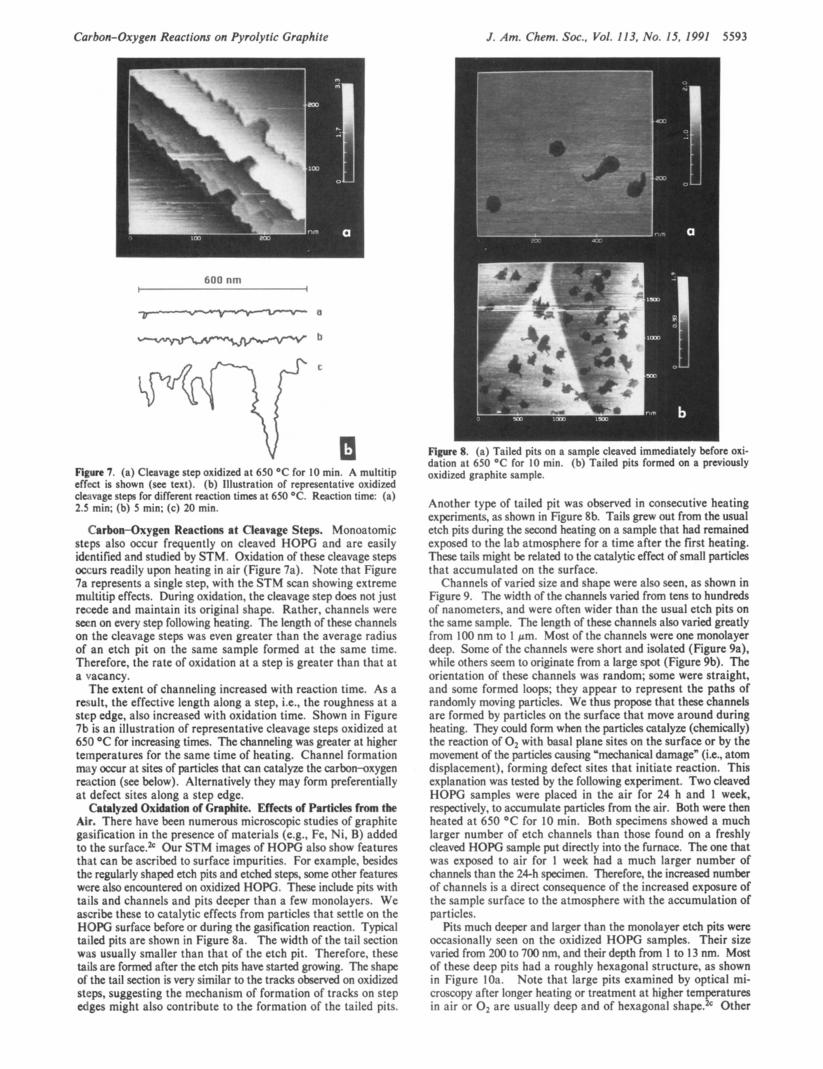
V Figure 7. (a) Cleavage step oxidized at 650 OC for 10 min. A multitip effect is shown (see text). (b) Illustration of representative oxidized clcivage steps for different reaction times at 650 OC. Reaction time: (a) 2.5 min: (b) 5 min; (c) 20 min.
Carbon-Oxygen Reactions at Cleavage Steps. Monoatomic steps also occur frequently on cleaved HOPG and are easily identified and studied by STM. Oxidation of these cleavage steps occurs readily upon heating in air (Figure 7a). Note that Figure 7a represents a single step, with the STM scan showing extreme multitip effects. During oxidation, the cleavage step does not just recede and maintain its original shape. Rather, channels were seen on every step following heating. The length of these channels on the cleavage steps was even greater than the average radius of an etch pit on the same sample formed at the same time. Therefore, the rate of oxidation at a step is greater than that at a vacancy.
The extent of channeling increased with reaction time. As a result, the effective length along a step, Le., the roughness at a step edge, also increased with oxidation time. Shown in Figure 7b is an illustration of representative cleavage steps oxidized at 650 OC for increasing times. The channeling was greater at higher temperatures for the same time of heating. Channel formation may occur at sites of particles that can catalyze the carbowoxygen reaction (see below). Alternatively they may form preferentially at defect sites along a step edge.
Catalyzed Oxidation of Graphite. Effects of Particles from the Air. There have been numerous microscopic studies of graphite gasification in the presence of materials (e.g., Fe, Ni, B) added to the surface.2c Our STM images of HOPG also show features that can be ascribed to surface impurities. For example, besides the regularly shaped etch pits and etched steps, some other features were also encountered on oxidized HOPG. These include pits with tails and channels and pits deeper than a few monolayers. We ascribe these to catalytic effects from particles that settle on the HOPG surface before or during the gasification reaction. Typical tailed pits are shown in Figure 8a. The width of the tail section was usually smaller than that of the etch pit. Therefore, these tails are formed after the etch pits have started growing. The shape of the tail section is very similar to the tracks observed on oxidized steps, suggesting the mechanism of formation of tracks on step edges might also contribute to the formation of the tailed pits.
Figure 8. (a) Tailed pits on a sample cleaved immediately before oxi- dation at 650 "C for I O min. (b) Tailed pits formed on a previously oxidized graphite sample.
Another type of tailed pit was observed in consecutive heating experiments, as shown in Figure 8b. Tails grew out from the usual etch pits during the second heating on a sample that had remained exposed to the lab atmosphere for a time after the first heating. These tails might be related to the catalytic effect of small particles that accumulated on the surface.
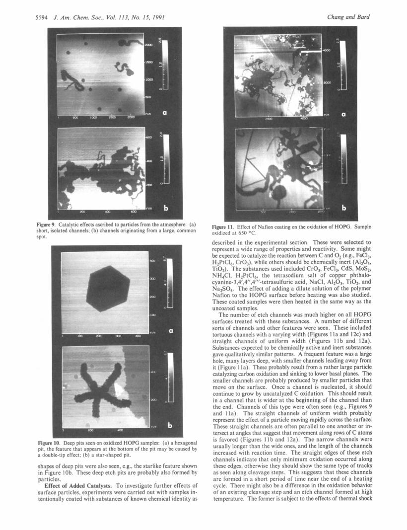
Channels of varied size and shape were also seen, as shown in Figure 9. The width of the channels varied from tens to hundreds of nanometers, and were often wider than the usual etch pits on the same sample. The length of these channels also varied greatly from 100 nm to 1 pm. Most of the channels were one monolayer deep. Some of the channels were short and isolated (Figure 9a), while others seem to originate from a large spot (Figure 9b). The orientation of these channels was random; some were straight, and some formed loops; they appear to represent the paths of randomly moving particles. We thus propose that these channels are formed by particles on the surface that move around during heating. They could form when the particles catalyze (chemically) the reaction of O2 with basal plane sites on the surface or by the movement of the particles causing 'mechanical damage" (i.e., atom displacement), forming defect sites that initiate reaction. This explanation was tested by the following experiment. Two cleaved HOPG samples were placed in the air for 24 h and 1 week, respectively, to accumulate particles from the air. Both were then heated at 650 "C for 10 min. Both specimens showed a much larger number of etch channels than those found on a freshly cleaved HOPG sample put directly into the fumace. The one that was exposed to air for 1 week had a much larger number of channels than the 24-h specimen. Therefore, the increased number of channels is a direct consequence of the increased exposure of the sample surface to the atmosphere with the accumulation of particles.
Pits much deeper and larger than the monolayer etch pits were occasionally seen on the oxidized HOPG samples. Their size varied from 200 to 700 nm, and their depth from 1 to 13 nm. Most of these deep pits had a roughly hexagonal structure, as shown in Figure loa. Note that large pits examined by optical mi- croscopy after longer heating or treatment at higher temperatures in air or O2 are usually deep and of hexagonal shape.*' Other
5594 J . Am. Chem. SOC., Vol. 113, No. IS, 1991 Chang and Bard
Fiw 9. Catalytic effects ascribed to particles from the atmmphcre: short, isolated channels; (b) channels originating from a large, comn SDOt .
(a) ion
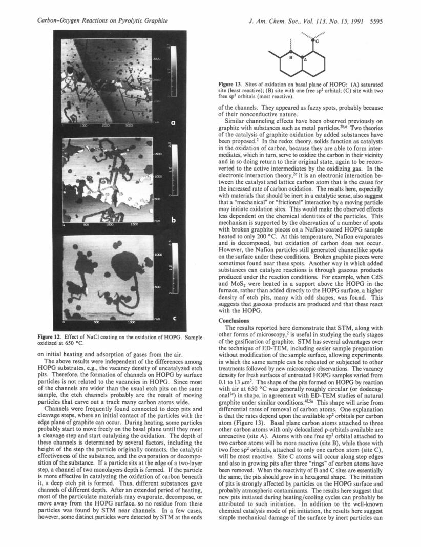
Figure 11. Effcct of \:ifion coating on the oxidation of HOPG. Sa oxidized at 650 “ C .
.mple
Fimre 10. Deep pits secn on oxidi7ed HOPG samples: ( a ) ;I hcxagonal pit. the feature that appears at the bottom of the pit may be caused by a double-tip effect; (b) a star-shaped pit.
shapes of deep pits were also seen, e.g., the starlike feature shown in Figure 1 Ob. These deep etch pits are probably also formed by particles.
Effect of Added Catalysts. To investigate further effects of surface particles, experiments were carried out with samples in- tentionally coated with substances of known chemical identity as
described in the experimental section. These were selected to represent a wide range of properties and reactivity. Some might be expected to catalyze the reaction between C and O2 (e.g., FeCI,, H2PtC16, CrO,), while others should be chemically inert (Al2o3, Ti02). The substances used included CrO,, FeCI,, CdS, MoS2, NH,CI, H2PtC16, the tetrasodium salt of copper phthalo- cya~ine”,4’,4’’,4’’’-tetrasulfuric acid, NaCI, A1203, Ti02, and Na2S04. The effect of adding a dilute solution of the polymer Nafion to the HOPG surface before heating was also studied. These coated samples were then heated in the same way as the uncoated samples.
The number of etch channels was much higher on all HOPG surfaces treated with these substances. A number of different sorts of channels and other features were seen. These included tortuous channels with a varying width (Figures 1 l a and 12c) and straight channels of uniform width (Figures 1 Ib and 12a). Substances expected to be chemically active and inert substances gave qualitatively similar patterns. A frequent feature was a large hole, many layers deep, with smaller channels leading away from it (Figure 1 la). These probably result from a rather large particle catalyzing carbon oxidation and sinking to lower basal planes. The smaller channels are probably produced by smaller particles that move on the surface. Once a channel is nucleated, it should continue to grow by uncatalyzed C oxidation. This should result in a channel that is wider at the beginning of the channel than the end. Channels of this type were often seen (e.g., Figures 9 and Ila). The straight channels of uniform width probably represent the effect of a particle moving rapidly across the surface. These straight channels are often parallel to one another or in- tersect at angles that suggest that movement along rows of C atoms is favored (Figures 1 1 b and 12a). The narrow channels were usually longer than the wide ones, and the length of the channels increased with reaction time. The straight edges of these etch channels indicate that only minimum oxidation occurred along these edges, otherwise they should show the same type of tracks as seen along cleavage steps. This suggests that these channels are formed in a short period of time near the end of a heating cycle. There might also be a difference in the oxidation behavior of an existing cleavage step and an etch channel formed at high temperature. The former is subject to the effects of thermal shock
Carbon-Oxygen Reactions on Pyrolytic Graphite J . Am. Chem. SOC., Vol. 113. No. IS, 1991 5595
- 1
Figure 12. Effect of NaCl coating on the oxidation of HOPG. Sample oxidized at 650 "C.
on initial heating and adsorption of gases from the air. The above results were independent of the differences among
HOPG substrates, e.g., the vacancy density of uncatalyzed etch pits. Therefore, the formation of channels on HOPG by surface particles is not related to the vacancies in HOPG. Since most of the channels are wider than the usual etch pits on the same sample, the etch channels probably are the result of moving particles that carve out a track many carbon atoms wide.
Channels were frequently found connected to deep pits and cleavage steps, where an initial contact of the particles with the edge plane of graphite can occur. During heating, some particles probably start to move freely on the basal plane until they meet a cleavage step and start catalyzing the oxidation. The depth of these channels is determined by several factors, including the height of the step the particle originally contacts, the catalytic effectiveness of the substance, and the evaporation or decompo- sition of the substance. If a particle sits at the edge of a two-layer step, a channel of two monolayers depth is formed. If the particle is more effective in catalyzing the oxidation of carbon beneath it, a deep etch pit is formed. Thus, different substances gave channels of different depth. After an extended period of heating, most of the particulate materials may evaporate, decompose, or move away from the HOPG surface, so no residue from these particles was found by STM near channels. In a few cases, however, some distinct particles were detected by STM at the ends
W Figure 13. Sites of oxidation on basal plane of HOW: (A) saturated site (least reactive); (B) site with one free sp2 orbital; (C) site with two free sp2 orbitals (most reactive).
of the channels. They appeared as fuzzy spots, probably because of their nonconductive nature.
Similar channeling effects have been observed previously on graphite with substances such as metal particles.2b*c Two theories of the catalysis of graphite oxidation by added substances have been proposed.2 In the redox theory, solids function as catalysts in the oxidation of carbon, because they are able to form inter- mediates, which in turn, serve to oxidize the carbon in their vicinity and in so doing return to their original state, again to be recon- verted to the active intermediates by the oxidizing gas. In the electronic interaction theory,2c it is an electronic interaction be- tween the catalyst and lattice carbon atom that is the cause for the increased rate of carbon oxidation. The results here, especially with materials that should be inert in a catalytic sense, also suggest that a "mechanical" or 'frictional" interaction by a moving particle may initiate oxidation sites. This would make the observed effects less dependent on the chemical identities of the particles. This mechanism is supported by the observation of a number of spots with broken graphite pieces on a Nafion-coated HOPG sample heated to only 200 "C. At this temperature, Nafion evaporates and is decomposed, but oxidation of carbon does not occur. However, the Nafion particles still generated channellike spots on the surface under these conditions. Broken graphite pieces were sometimes found near these spots. Another way in which added substances can catalyze reactions is through gaseous products produced under the reaction conditions. For example, when CdS and Most were heated in a support above the HOPG in the furnace, rather than added directly to the HOPG surface, a higher density of etch pits, many with odd shapes, was found. This suggests that gaseous products are produced and that these react with the HOPG. Conclusions
The results reported here demonstrate that STM, along with other forms of microscopy,2 is useful in studying the early stages of the gasification of graphite. STM has several advantages over the technique of ED-TEM, including easier sample preparation without modification of the sample surface, allowing experiments in which the same sample can be reheated or subjected to other treatments followed by new microscopic observations. The vacancy density for fresh surfaces of untreated HOPG samples varied from 0.1 to 13 pm2. The shape of the pits formed on HOPG by reaction with air at 650 "C was generally roughly circular (or dodecag- onaltc) in shape, in agreement with ED-TEM studies of natural graphite under similar This shape will arise from differential rates of removal of carbon atoms. One explanation is that the rates depend upon the available sp2 orbitals per carbon atom (Figure 13). Basal plane carbon atoms attached to three other carbon atoms with only delocalized porbitals available are unreactive (site A). Atoms with one free sp2 orbital attached to two carbon atoms will be more reactive (site B), while those with two free sp2 orbitals, attached to only one carbon atom (site C), will be most reactive. Site C atoms will occur along step edges and also in growing pits after three "rings" of carbon atoms have been removed. When the reactivity of B and C sites are essentially the same, the pits should grow in a hexagonal shape. The initiation of pits is strongly affected by particles on the HOPG surface and probably atmospheric contaminants. The results here suggest that new pits initiated during heating/cooling cycles can probably be attributed to such initiation. In addition to the well-known chemical catalysis mode of pit initiation, the results here suggest simple mechanical damage of the surface by inert particles can
5596 J . Am. Chem. SOC. 1991, 113, 5596-5605
create carbon vacancies and initiate pit formation. The rate of removal of carbon atoms in air at 650 OC was about
0.5 atom/site atom/s. By observing the change in pit dimensions with time, it is thus possible to study the kinetics of the reaction on an almost atom-by-atom basis. This would be easier if the reaction could be carried out in situ, while the sample was held in the STM. However, it is difficult to imagine operating the STM under these high-temperature conditions while still maintaining the needed freedom from thermal drift. It might be possible to study the reaction of HOPG with more reactive species at lower temperatures, assuming that the STM components can be pro- tected under these conditions. Similar surface reactions and pit formation could also be studied with other substrates (e& metals) by this approach.
Pits have been formed in HOPG with the STM by applying a voltage pulse to the tip in a moist atmosphere (but not in vacuum).13 These were quite similar in appearance to those
(13) Albrecht, T. R.; Dovek, M. M.; Kirk, M. D.; Lang, C. A.; Quate, C. F. Appl. Phys. Lett. 1989, 55, 1727.
reported here and, as pointed out by Quate,14 could result from the generation of chemical species by the high field at the tip, which can then react with the graphite. Dioxygen itself will not react with HOPG at ambient temperatures, so unless it is activated during its formation, other intermediates, such as oxygen atoms, dioxygen ions, or hydroxyl radicals, are more likely as the reac- tants. As discussed earlier,' these pits are useful in STM studies as surface markers, calibrators of the Z-axis of the STM, and perhaps as molecular containers. They may also prove useful, both in STM and electrochemical studies, as specific sites for nucleation and reaction. Studies of this type are currently under way in our laboratory.
Acknowledgment. The support of this research by the Texas Advanced Research Program and the National Science Foun- dation (Grant CHE8805685) is gratefully acknowledged. We thank Dr. Jeff Cook for obtaining the AES and XPS results.
(14) Quate, C. F. NATO Science Forum '90, Bairritz, France, Sept. 16-21, 1990. (To be published in the NATO Series; Plenum Press: New York).
Molecular Dynamics Simulation and NMR Study of Water-Acetonitrile Mixtures Helena Kovacs and Aatto Laaksonen* Contribution from the Division of Physical Chemistry, Arrhenius Luboratory, University of Stockholm, S-106 91 Stockholm, Sweden. Received October 9, 1990
Abstract: Pure water, pure acetonitrile, and binary mixtures of these two liquids at 0.12,0.50, and 0.88 molar fractions were simulated by using the molecular dynamics technique with two different sets of effective pair potentials. The reorientational correlation times were deduced from the NMR relaxation of I4N in acetonitrile and 170 in water for comparison.. A manifold increase was observed in the amplitudes of the water-water radial distribution functions upon dilution with acetonitrile, while the acetonitrile arrangement remained relatively intact. The intercomponent interactions were also intensified as moving from the high to low water concentrations. The simulations reproduced the experimental trends in the self-diffusion and reorientation of acetonitrile but rendered too high a mobility for pure water, a feature known previously. At low water content, however, the agreement between the simulated and observed dynamics of water was better. The simulations indicate a slight initial enhancement of the hydrogen-bonded structure of water upon dilution, followed by a breakdown leading to heterogeneity at the molecular level. In the diluted aqueous solution, the presence of water dimers, trimers, tetramers, etc. leads to faster but correlated molecular motions.
1. Introduction The study of aqueous solutions is in general of considerable
interest not only because of the unique properties of water but also due to the crucial importance of water and its solutions in the biosphere. Owing to its remarkable ability to preferential solvation, the mixed solvent of water and acetonitrile makes a recurrent reaction media in physical organic chemistry' and also plays a role in atmospheric chemistry.2
In 1945, Frank and Evans3 introduced the 'iceberg hypothesis". Their idea was that nonelectrolytes with inert parts-when dis- solved in water at low concentrations-will enhance the water structure instead of occupying interstitial sites in the icelike lattice. Since that time, the concept, as well as insight into this so called hydrophobic effect? has become much refined. The hydrophobic interactions are of two kinds, hydrophobic hydration of the solute (Le., the iceberg formation, or hydration of the second kind as it is also called) and hydrophobic association of the solute mol-
(1) Engberts, J. B. F. N. Faraday Discuss. Chem. SOC. 1988, 85, 289. (2) Deakyne, C. A.; Meot-Ner, M.; Campbell, C. L.; Hughes, M. G.;
(3) Frank, H. S.; Evans, M. W. J . Chem. Phys. 1945, 13, 507. (4) Franks, F. Water. A Comprehensiue Treatise; Plenum Press: New
Murphy, S. P. J. Chem. Phys. 1986, 84, 4958.
York-London, 1973.
ecules. One of the subjects of both interest and some controversy in this context has been acetonitrile, which is an aprotic but highly polar liquid.
Experimental Studies of Water-Acetonitrile Mixtures. The target of the present study is the characterization of the properties and their concentration dependence in the binary solvent mixture of water and acetonitrile. The study focuses on three compositions of water-acetonitrile from three distinct regions in which different solution structures are proposed to exist. Considering the available literature, several thermodynamic studies on aqueous solutions of acetonitrile5-" have been published, as well as investigations
(5) Robertson, R. E.; Sugamori, S. E. Can. J . Chem. 1972, 50, 1353. (6) Moreau, C.; Douhbret, G. J . Chim. Phys. 1974, 71, 1313. Mqreau,
C.; Douhtret, G. Thermochim. Acta 1975,13, 385. Moreau, C.; Douhheret, G. J. Chem. Thermodyn. 1976,8,403. Douhbret, G.; Moreau, C.; Viallard, A. Fluid Phase Equilib. 1985, 22, 289. Douhbret, G.; Moreau, C.; Viallard, A. Fluid Phase Equilib. 1986, 26, 221.
(7) Davis, M. I. Thermochim. Acta 1983,63,67. Davis, M. I. Therm@ chim. Acta 1984, 73, 149. Davis, M. I.; DouhEret, G. Thermochim. Acta 1986, 104, 203. (8) Davis, M. 1.; Douhbret, G. Thermochim. Acta 1987, 116, 183. (9) Luhrs, C.; Schwitzgebel, G. Ber. Bunsen-Ges. Phys. Chem. 1979,83,
(IO) de Visser, C.; Heuvelsland, W. J. M.; Dunn, L. A.; Somsen, G. J . 623.
Chem. SOC., Faraday Trans. I 1978, 74, 1 1 59.
0002-7863/91/1513-5596$02.50/0 0 1991 American Chemical Society