Embed Size (px)
Citation preview
Reaction Engineering for
Environmentally Benign Processes
Reactor Selection Strategy
M.P. Dudukovic
Module 6
Homogeneous systems
Heterogeneous systems
Systems (multi-scale) approach
S1
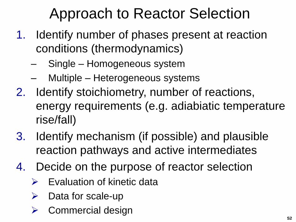
Approach to Reactor Selection
1. Identify number of phases present at reaction
conditions (thermodynamics)
– Single – Homogeneous system
– Multiple – Heterogeneous systems
2. Identify stoichiometry, number of reactions,
energy requirements (e.g. adiabiatic temperature
rise/fall)
3. Identify mechanism (if possible) and plausible
reaction pathways and active intermediates
4. Decide on the purpose of reactor selection
Evaluation of kinetic data
Data for scale-up
Commercial designS2
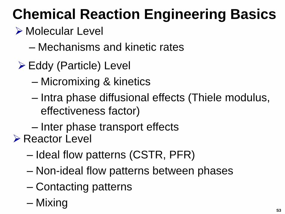
Chemical Reaction Engineering BasicsMolecular Level
– Mechanisms and kinetic rates
Eddy (Particle) Level
– Micromixing & kinetics
– Intra phase diffusional effects (Thiele modulus,
effectiveness factor)
– Inter phase transport effectsReactor Level
– Ideal flow patterns (CSTR, PFR)
– Non-ideal flow patterns between phases
– Contacting patterns
– MixingS3
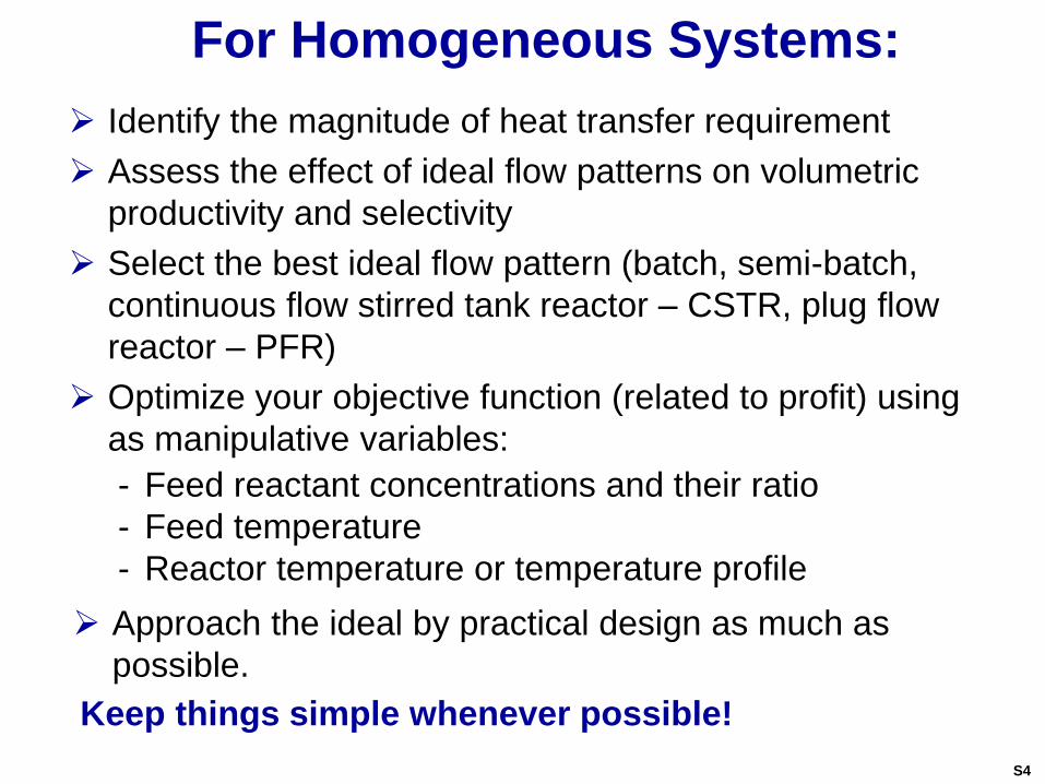
For Homogeneous Systems:
Identify the magnitude of heat transfer requirement
Assess the effect of ideal flow patterns on volumetric
productivity and selectivity
Select the best ideal flow pattern (batch, semi-batch,
continuous flow stirred tank reactor – CSTR, plug flow
reactor – PFR)
Optimize your objective function (related to profit) using
as manipulative variables:
- Feed reactant concentrations and their ratio
- Feed temperature
- Reactor temperature or temperature profile
Keep things simple whenever possible!
Approach the ideal by practical design as much as
possible.
S4
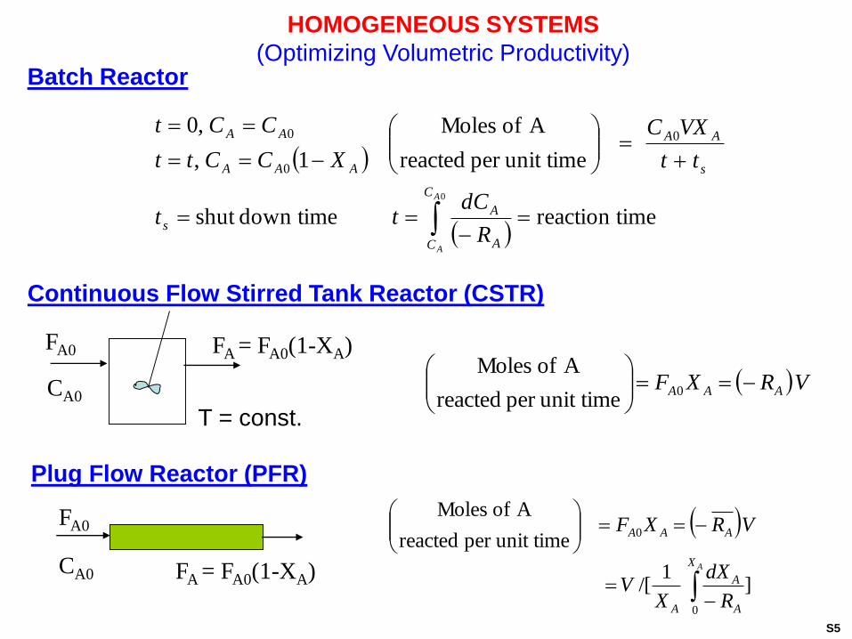
HOMOGENEOUS SYSTEMS
(Optimizing Volumetric Productivity)Batch Reactor
Plug Flow Reactor (PFR)
Continuous Flow Stirred Tank Reactor (CSTR)
FA0
CA0
FA = FA0(1-XA)
T = const.
FA0
CA0 FA = FA0(1-XA)
0
imereaction t down timeshut
unit timeper reacted
A of Moles
1,
,00
0
0
A
A
C
C A
As
s
AA
AAA
AA
R
dCtt
tt
VXC
XCCtt
CCt
VRXF AAA
0
unit timeper reacted
A of Moles
AX
A
A
A
AAA
R
dX
XV
VRXF
0
0
]1
/[
unit timeper reacted
A of Moles
S5
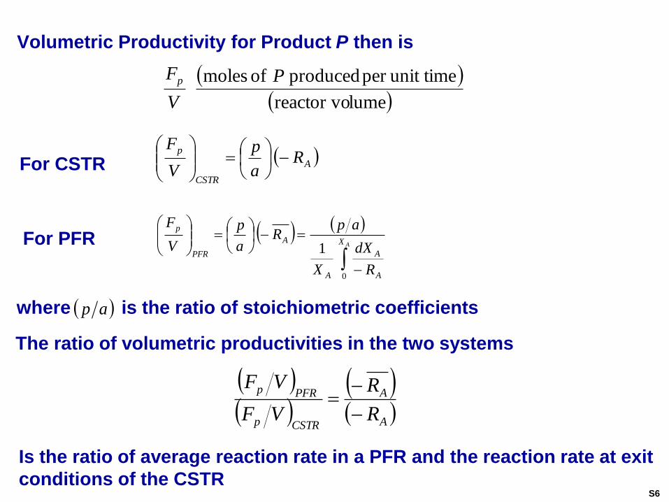
where is the ratio of stoichiometric coefficients
Volumetric Productivity for Product P then is
lumereactor vo
unit timeper produced of moles P
V
Fp
A
CSTR
pR
a
p
V
F
For CSTR
AX
A
A
A
A
PFR
p
R
dX
X
apR
a
p
V
F
0
1For PFR
ap
The ratio of volumetric productivities in the two systems
A
A
CSTRp
PFRp
R
R
VF
VF
Is the ratio of average reaction rate in a PFR and the reaction rate at exit
conditions of the CSTRS6
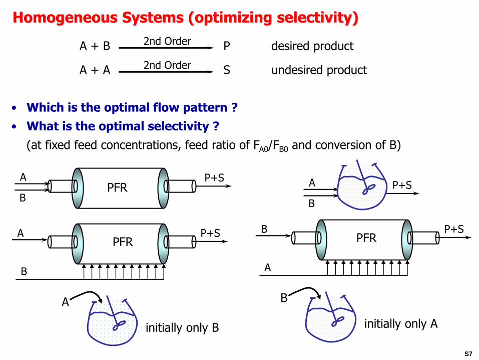
Homogeneous Systems (optimizing selectivity)
A + B P desired product2nd Order
A + A S undesired product2nd Order
• Which is the optimal flow pattern ?
• What is the optimal selectivity ?
(at fixed feed concentrations, feed ratio of FA0/FB0 and conversion of B)
BPFR
A P+S
A P+SPFR
B
B P+SPFR
A
B
A P+S
initially only B
A
initially only A
B
S7
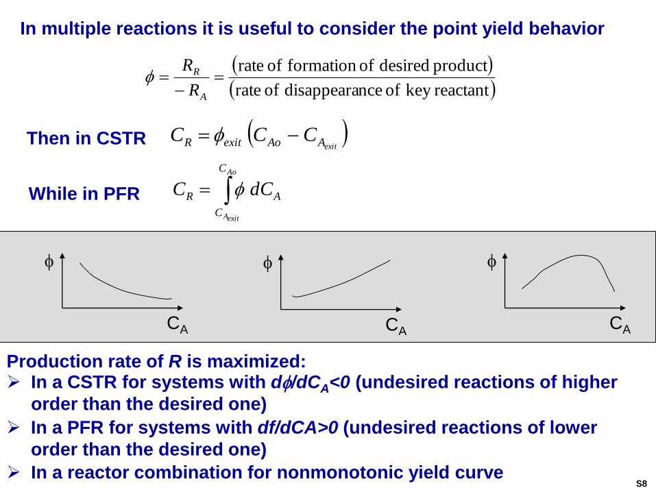
In multiple reactions it is useful to consider the point yield behavior
reactantkey of ncedisappeara of rate
product desired offormation of rate
A
R
R
R
exitAAoexitR CCC Then in CSTR
Ao
exitA
C
C
AR dCC While in PFR
Production rate of R is maximized: In a CSTR for systems with d/dCA<0 (undesired reactions of higher
order than the desired one)
CA
CA
CA
In a reactor combination for nonmonotonic yield curve
In a PFR for systems with df/dCA>0 (undesired reactions of lower
order than the desired one)
S8
Other Simple Rules Worth Remembering
In consecutive reactions production of intermediate is always more favored in a PFR than in a CSTR
For exothermic reactions maximum volumetric productivity is reached at an optimal temperature which is a function of conversion
When desired reaction has the highest activation energy select the highest temperature for best selectivity
When desired reaction has the lowest activation energy lowest practical temperature optimizes selectivity
For intermediate activation energy of desired reaction an optimal temperature or temperature profile can be found
For lumping complex reaction schemes into patterns to
analyze see Levenspiel, O., Chem. React. Eng.
S9
Avoid!Bad!
model seriesin or tanks dispersionby Model
1
10
1
01
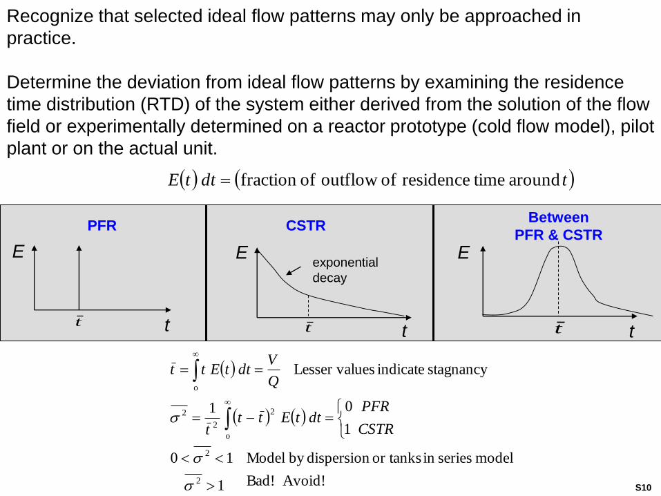
stagnancy indicate uesLesser val
2
2
o
2
2
2
o
CSTR
PFRdttEtt
t
Q
VdttEtt
Recognize that selected ideal flow patterns may only be approached in
practice.
Determine the deviation from ideal flow patterns by examining the residence
time distribution (RTD) of the system either derived from the solution of the flow
field or experimentally determined on a reactor prototype (cold flow model), pilot
plant or on the actual unit.
tdttE around timeresidence of outflow offraction
tdttE about timeresidence of outflow offraction
E
t
E
t
E
tt
PFR CSTRBetween
PFR & CSTR
exponential
decay
tt
S10
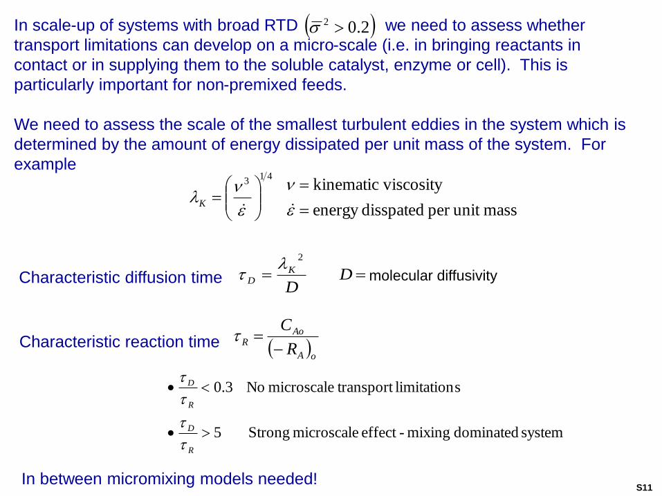
oA
AoR
R
C
Characteristic reaction time
system dominated mixing-effect microscale Strong5
slimitation transportmicroscale No3.0
R
D
R
D
massunit per disspatedenergy
viscositykinematic41
3
K
In between micromixing models needed!
2
DD
KD
Characteristic diffusion time
In scale-up of systems with broad RTD we need to assess whether
transport limitations can develop on a micro-scale (i.e. in bringing reactants in
contact or in supplying them to the soluble catalyst, enzyme or cell). This is
particularly important for non-premixed feeds.
We need to assess the scale of the smallest turbulent eddies in the system which is
determined by the amount of energy dissipated per unit mass of the system. For
example
2.02
molecular diffusivity
S11
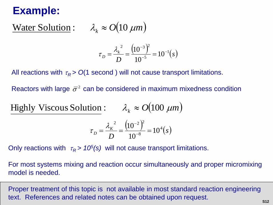
All reactions with R > O(1 second ) will not cause transport limitations.
Reactors with large can be considered in maximum mixedness condition2
s
D
kD
1
5
232
1010
10
mOk 10:SolutionWater
Only reactions with R > 105(s) will not cause transport limitations.
For most systems mixing and reaction occur simultaneously and proper micromixing
model is needed.
Proper treatment of this topic is not available in most standard reaction engineering
text. References and related notes can be obtained upon request.
s
D
KD
4
8
222
1010
10
Example:
mOk 100:Solution ViscousHighly
S12
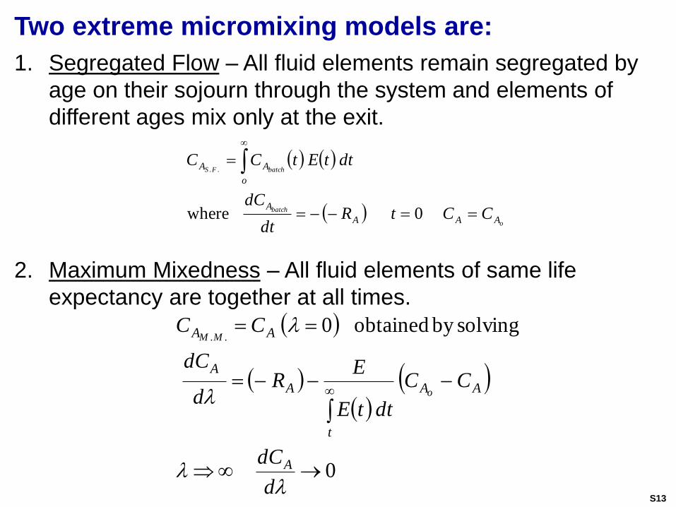
o
batch
batchFS
AAA
A
o
AA
CCtRdt
dC
dttEtCC
0where
..
1. Segregated Flow – All fluid elements remain segregated by
age on their sojourn through the system and elements of
different ages mix only at the exit.
Two extreme micromixing models are:
0
solvingby obtained0..
d
dC
CC
dttE
ER
d
dC
CC
A
AA
t
A
A
AA
o
MM
2. Maximum Mixedness – All fluid elements of same life
expectancy are together at all times.
S13
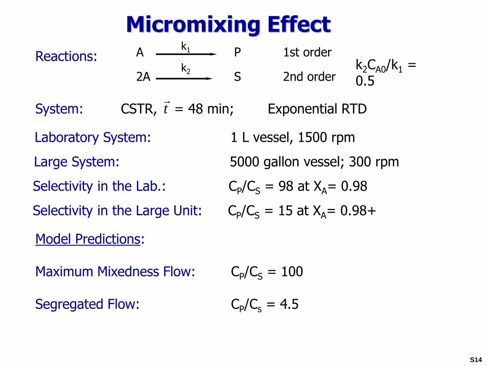
Micromixing EffectA P 1st order
k1
2A S 2nd orderk2
k2CA0/k1 = 0.5
Reactions:
System: CSTR, = 48 min; Exponential RTD
Laboratory System: 1 L vessel, 1500 rpm
Large System: 5000 gallon vessel; 300 rpm
Selectivity in the Lab.: CP/CS = 98 at XA= 0.98
Selectivity in the Large Unit: CP/CS = 15 at XA= 0.98+
Model Predictions:
Maximum Mixedness Flow: CP/CS = 100
Segregated Flow: CP/Cs = 4.5
t
S14
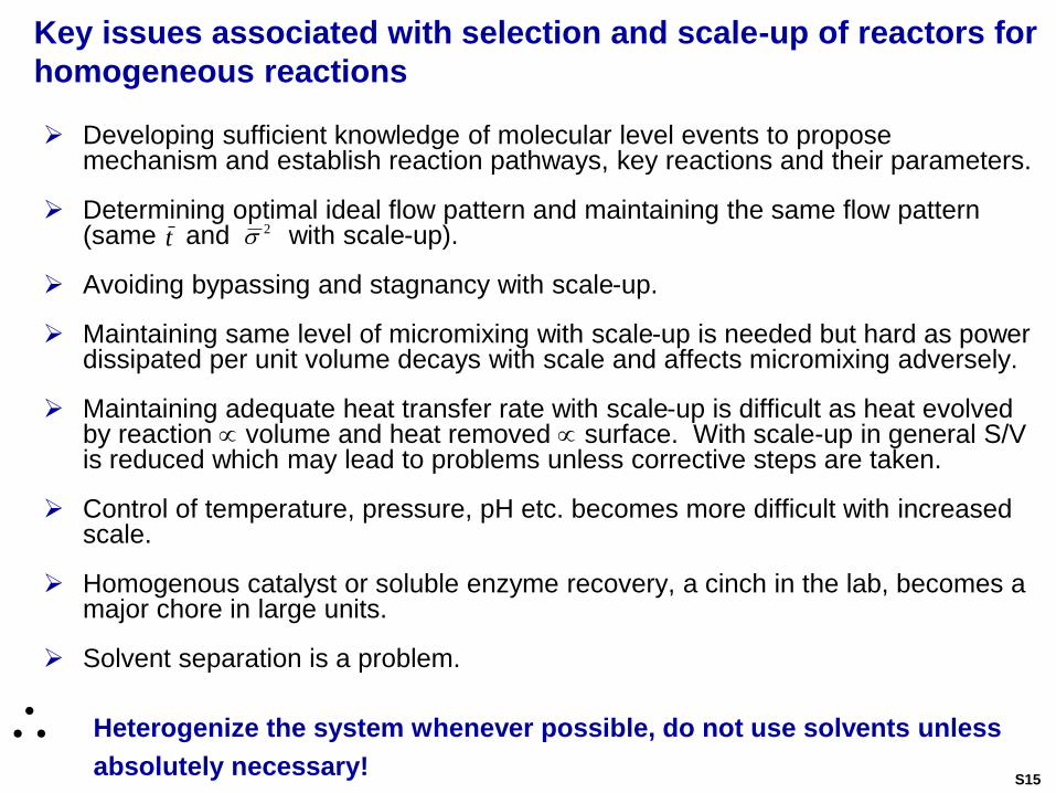
Key issues associated with selection and scale-up of reactors for
homogeneous reactions
Developing sufficient knowledge of molecular level events to propose mechanism and establish reaction pathways, key reactions and their parameters.
Determining optimal ideal flow pattern and maintaining the same flow pattern (same and with scale-up).
Avoiding bypassing and stagnancy with scale-up.
Maintaining same level of micromixing with scale-up is needed but hard as power dissipated per unit volume decays with scale and affects micromixing adversely.
Maintaining adequate heat transfer rate with scale-up is difficult as heat evolved by reaction volume and heat removed surface. With scale-up in general S/V is reduced which may lead to problems unless corrective steps are taken.
Control of temperature, pressure, pH etc. becomes more difficult with increased scale.
Homogenous catalyst or soluble enzyme recovery, a cinch in the lab, becomes a major chore in large units.
Solvent separation is a problem.
t2
Heterogenize the system whenever possible, do not use solvents unless
absolutely necessary!S15
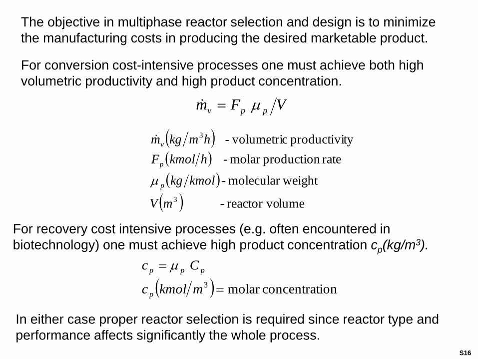
The objective in multiphase reactor selection and design is to minimize
the manufacturing costs in producing the desired marketable product.
For conversion cost-intensive processes one must achieve both high
volumetric productivity and high product concentration.
lumereactor vo -
weightmolecular -
rate productionmolar -
typroductivi c volumetri-
3
3
mV
kmolkg
hkmolF
hmkgm
p
p
v
For recovery cost intensive processes (e.g. often encountered in
biotechnology) one must achieve high product concentration cp(kg/m3).
ionconcentratmolar 3
mkmolc
Cc
p
ppp
In either case proper reactor selection is required since reactor type and
performance affects significantly the whole process.
VFm ppv
S16
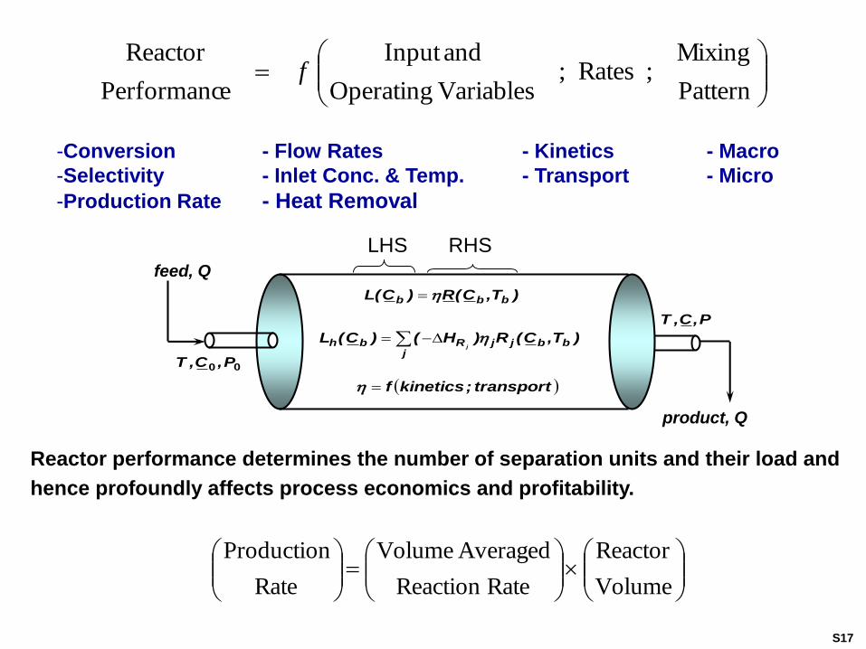
)T,C(R)C(L bbb
j
bbjjRbh )T,C(R)H()C(Lj
transport;kineticsf
00 P,C,T
P,C,T
feed, Q
product, Q
Reactor performance determines the number of separation units and their load and
hence profoundly affects process economics and profitability.
Pattern
Mixing; Rates;
Variables Operating
andInput
ePerformanc
Reactorf
-Conversion - Flow Rates - Kinetics - Macro
-Selectivity - Inlet Conc. & Temp. - Transport - Micro
-Production Rate - Heat Removal
LHS RHS
Volume
Reactor
RateReaction
Averaged Volume
Rate
Production
S17
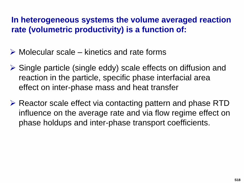
In heterogeneous systems the volume averaged reaction
rate (volumetric productivity) is a function of:
Molecular scale – kinetics and rate forms
Single particle (single eddy) scale effects on diffusion and
reaction in the particle, specific phase interfacial area
effect on inter-phase mass and heat transfer
Reactor scale effect via contacting pattern and phase RTD
influence on the average rate and via flow regime effect on
phase holdups and inter-phase transport coefficients.
S18
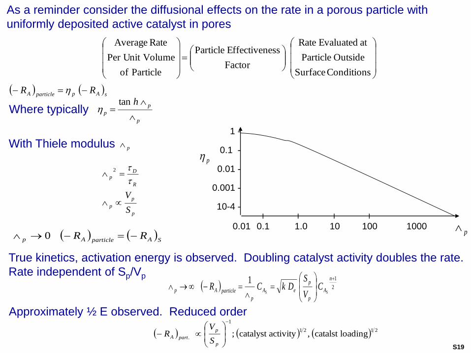
As a reminder consider the diffusional effects on the rate in a porous particle with
uniformly deposited active catalyst in pores
sApparticleA RR
p
p
p
h
tan
Conditions Surface
Outside Particle
at Evaluated Rate
Factor
essEffectiven Particle
Particle of
VolumePer Unit
Rate Average
Where typically
pWith Thiele modulus
p
p
p
R
Dp
S
V
2
True kinetics, activation energy is observed. Doubling catalyst activity doubles the rate.
Rate independent of Sp/Vp
1 -
0.1 -
0.01 -
0.001 -
10-4 -
0.01 0.1 1.0 10 100 1000
| | | |
p
p
SAparticleAp RR 0
2
11
n
A
p
p
eA
p
particleAp SSC
V
SDkCR
Approximately ½ E observed. Reduced order
2121
1
.loadingcatalst ,activitycatalyst ;
p
p
partAS
VR
S19
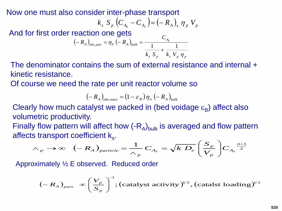
Now one must also consider inter-phase transport
ppsAAAps VRCCSksb
ppvps
A
bulkApartobsA
VkSk
CRR b
110
And for first order reaction one gets
The denominator contains the sum of external resistance and internal +
kinetic resistance.
Of course we need the rate per unit reactor volume so
Clearly how much catalyst we packed in (bed voidage B) affect also
volumetric productivity.
Finally flow pattern will affect how (-RA)bulk is averaged and flow pattern
affects transport coefficient ks.
2
11
n
A
p
p
eA
p
particleAp SSC
V
SDkCR
Approximately ½ E observed. Reduced order
2121
1
.loadingcatalst ,activitycatalyst ;
p
p
partAS
VR
bulkAoBreactobsA RR 1
S20
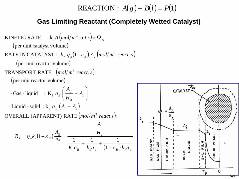
1 :REACTION PlBgA
Gas Limiting Reactant (Completely Wetted Catalyst)
pvBpsBl
A
g
H
g
BvoA
slp
a
g
B
sBpv
Av
kakaK
H
A
AkR
sreactmmol
AAa
AH
Aa
sreactmmol
sreactmmolAk
scatmmolAk
A
1
1111
:. RATE (APPARENT) OVERALL
k:solid-Liquid -
K:liquid-Gas -
lumereactor vounit per
. RATE TRANSPORT
lumereactor vounit per
.1 : CATALYST IN RATE
olumecatalyst vunit per
.: RATE KINETIC
3
s
11
3
3
3
S21
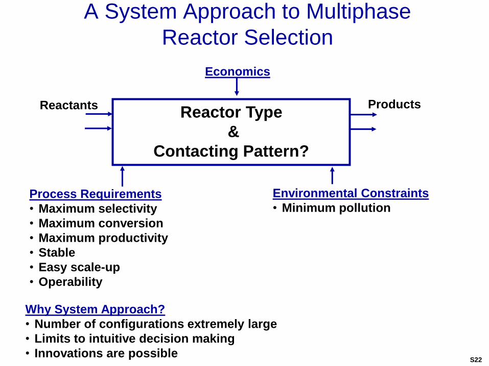
A System Approach to Multiphase
Reactor Selection
Process Requirements
• Maximum selectivity
• Maximum conversion
• Maximum productivity
• Stable
• Easy scale-up
• Operability
Environmental Constraints
• Minimum pollution
Why System Approach?
• Number of configurations extremely large
• Limits to intuitive decision making
• Innovations are possible
Reactor Type
&
Contacting Pattern?
Economics
Reactants Products
S22
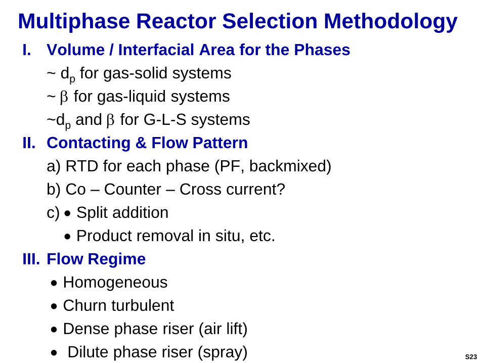
Multiphase Reactor Selection Methodology
I. Volume / Interfacial Area for the Phases
~ dp for gas-solid systems
~ b for gas-liquid systems
~dp and b for G-L-S systems
II. Contacting & Flow Pattern
a) RTD for each phase (PF, backmixed)
b) Co – Counter – Cross current?
c) Split addition
Product removal in situ, etc.
III. Flow Regime
Homogeneous
Churn turbulent
Dense phase riser (air lift)
Dilute phase riser (spray) S23
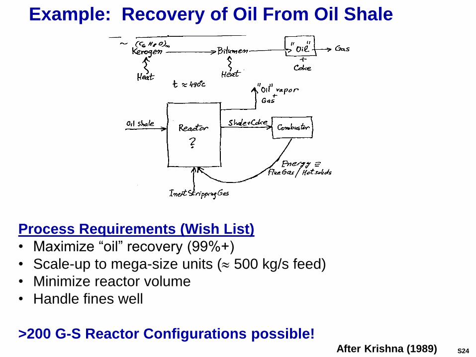
Example: Recovery of Oil From Oil Shale
Process Requirements (Wish List)
• Maximize “oil” recovery (99%+)
• Scale-up to mega-size units ( 500 kg/s feed)
• Minimize reactor volume
• Handle fines well
>200 G-S Reactor Configurations possible!After Krishna (1989) S24
S25
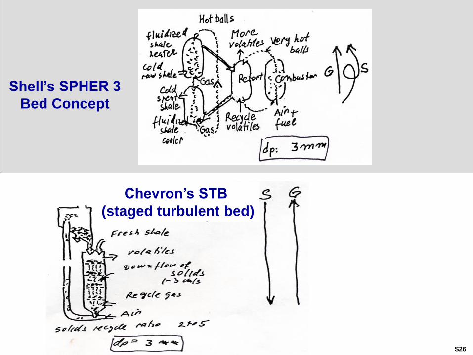
Shell’s SPHER 3
Bed Concept
Chevron’s STB
(staged turbulent bed)
S26
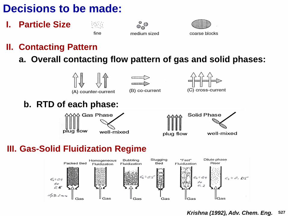
Decisions to be made:
I. Particle Size
II. Contacting Pattern
III. Gas-Solid Fluidization Regime
a. Overall contacting flow pattern of gas and solid phases:
b. RTD of each phase:
Krishna (1992), Adv. Chem. Eng. S27
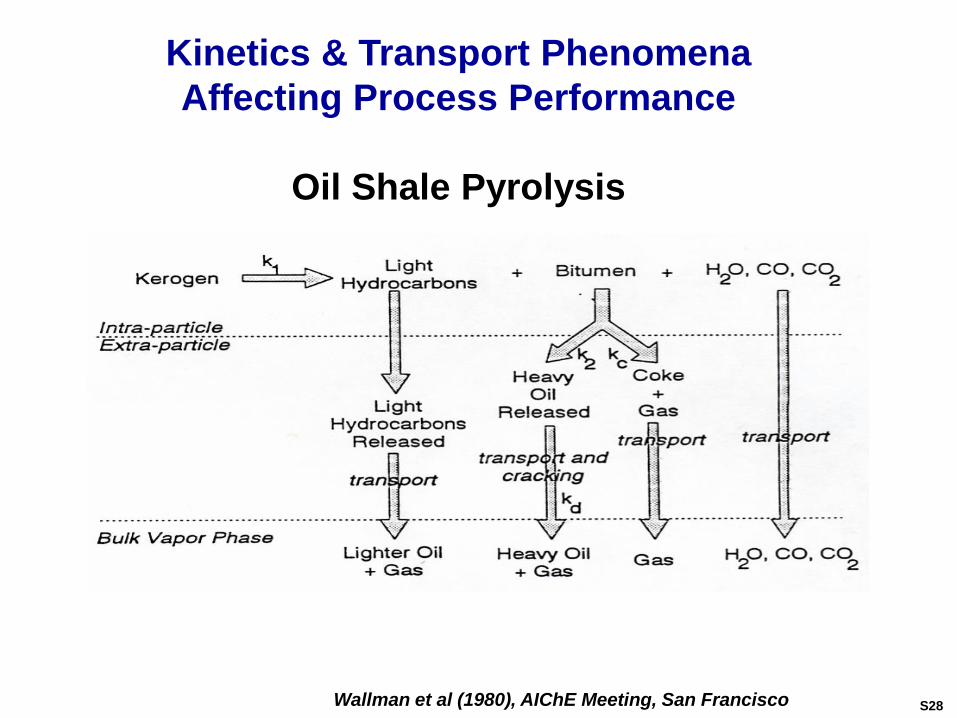
Kinetics & Transport Phenomena
Affecting Process Performance
Oil Shale Pyrolysis
Wallman et al (1980), AIChE Meeting, San Francisco S28
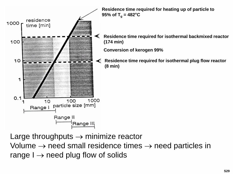
Large throughputs minimize reactor
Volume need small residence times need particles in
range I need plug flow of solids
Residence time required for heating up of particle to
95% of Tg = 482°C
Residence time required for isothermal backmixed reactor
(174 min)
Conversion of kerogen 99%
Residence time required for isothermal plug flow reactor
(8 min)
S29
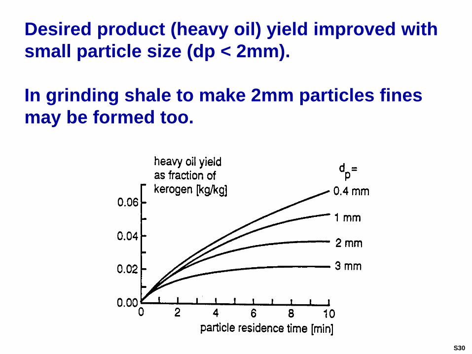
Desired product (heavy oil) yield improved with
small particle size (dp < 2mm).
In grinding shale to make 2mm particles fines
may be formed too.
S30
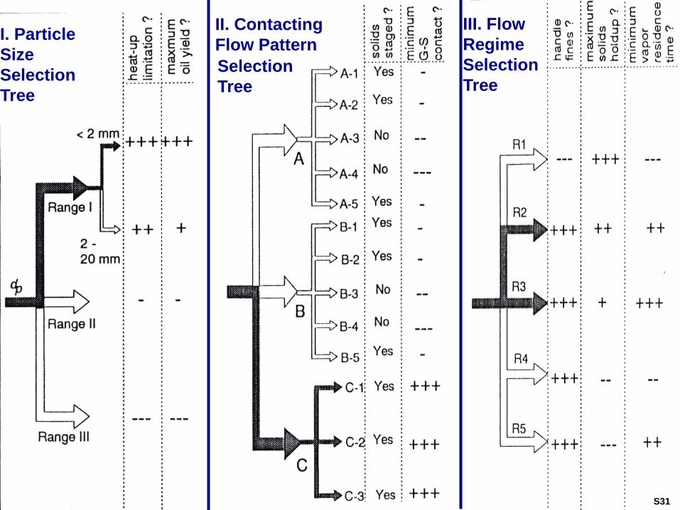
III. Flow
Regime
Selection
Tree
II. Contacting
Flow Pattern
Selection
Tree
I. Particle
Size
Selection
Tree
S31
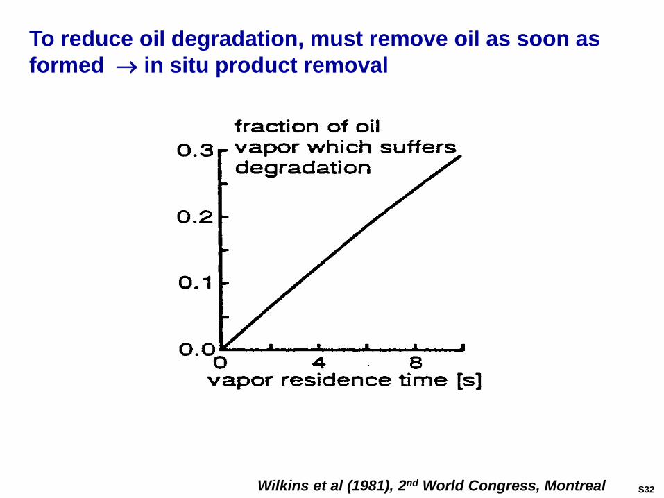
Wilkins et al (1981), 2nd World Congress, Montreal
To reduce oil degradation, must remove oil as soon as
formed in situ product removal
S32
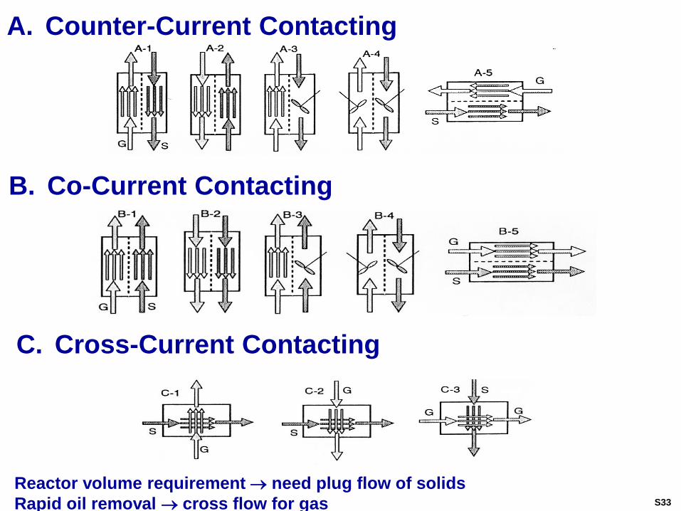
A. Counter-Current Contacting
B. Co-Current Contacting
C. Cross-Current Contacting
Reactor volume requirement need plug flow of solids
Rapid oil removal cross flow for gas S33
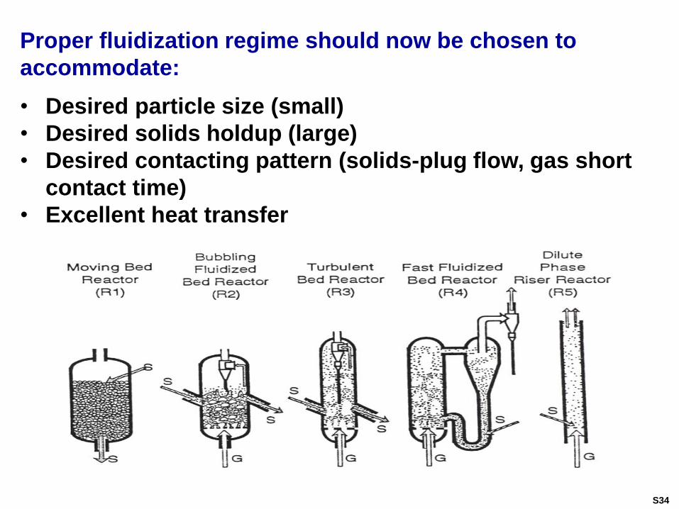
Proper fluidization regime should now be chosen to
accommodate:
• Desired particle size (small)
• Desired solids holdup (large)
• Desired contacting pattern (solids-plug flow, gas short
contact time)
• Excellent heat transfer
S34
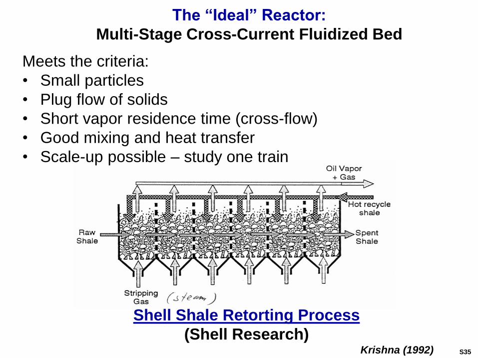
The “Ideal” Reactor:
Multi-Stage Cross-Current Fluidized Bed
Meets the criteria:
• Small particles
• Plug flow of solids
• Short vapor residence time (cross-flow)
• Good mixing and heat transfer
• Scale-up possible – study one train
Shell Shale Retorting Process
(Shell Research)Krishna (1992) S35
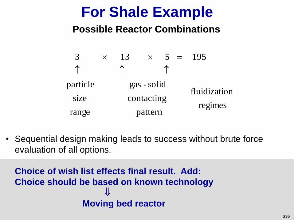
For Shale ExamplePossible Reactor Combinations
regimes
onfluidizati
pattern
contacting
solid-gas
range
size
particle
1955133
• Sequential design making leads to success without brute force
evaluation of all options.
Choice of wish list effects final result. Add:
Choice should be based on known technology
Moving bed reactor
S36
This example illustrates how consideration of all
scales leads to successful reactor selection
It also teaches that in situ separation when
possible is of high value and can sometimes be
achieved by:
Catalytic distillation
Selective adsorption or absorption
Membrane separation
Other means (e.g. dynamic reactor operation, etc.)
Think Out of the Box!
S37
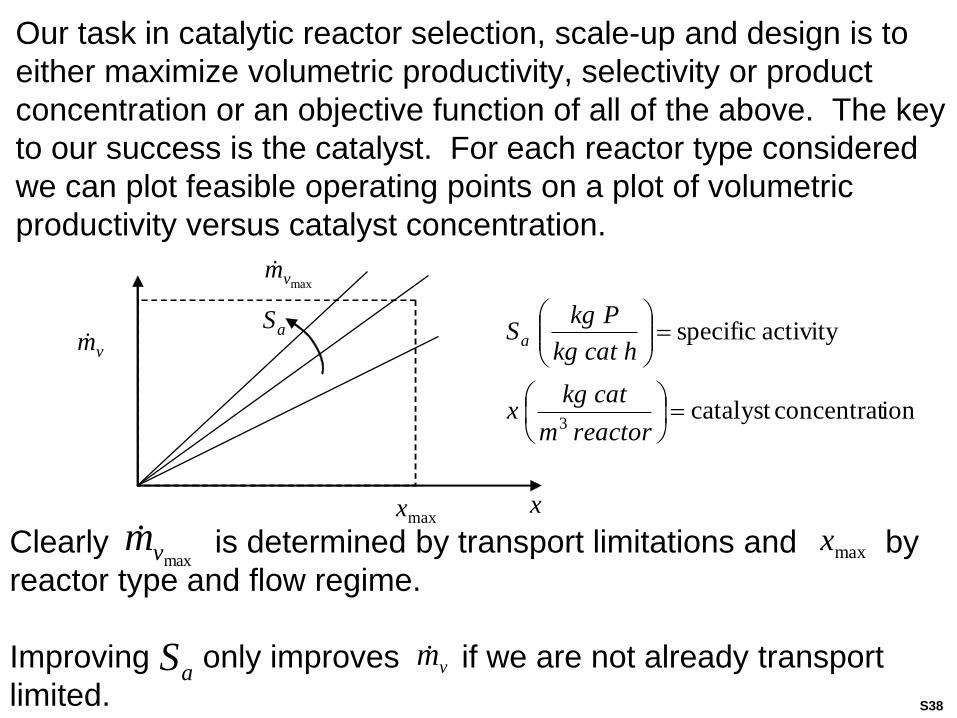
Clearly is determined by transport limitations and by
reactor type and flow regime.
Improving only improves if we are not already transport
limited.
Our task in catalytic reactor selection, scale-up and design is to
either maximize volumetric productivity, selectivity or product
concentration or an objective function of all of the above. The key
to our success is the catalyst. For each reactor type considered
we can plot feasible operating points on a plot of volumetric
productivity versus catalyst concentration.
vm
aS
vm
maxvm
maxx x
maxxmaxvm
aS
ionconcentratcatalyst
activity specific
3
reactorm
catkgx
hcatkg
PkgSa
S38
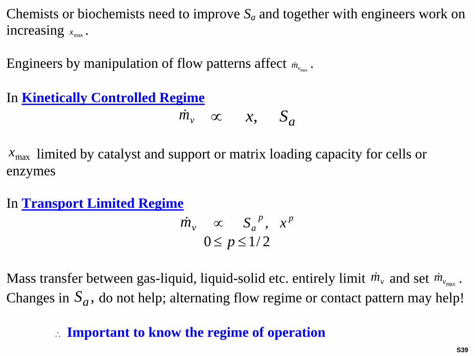
Chemists or biochemists need to improve Sa and together with engineers work on
increasing maxx .
Engineers by manipulation of flow patterns affect maxvm .
In Kinetically Controlled Regime
vm aSx,
maxx limited by catalyst and support or matrix loading capacity for cells or
enzymes
In Transport Limited Regime
vm pp
a xS ,
2/10 p
Mass transfer between gas-liquid, liquid-solid etc. entirely limit vm and set maxvm .
Changes in ,aS do not help; alternating flow regime or contact pattern may help!
Important to know the regime of operation
S39
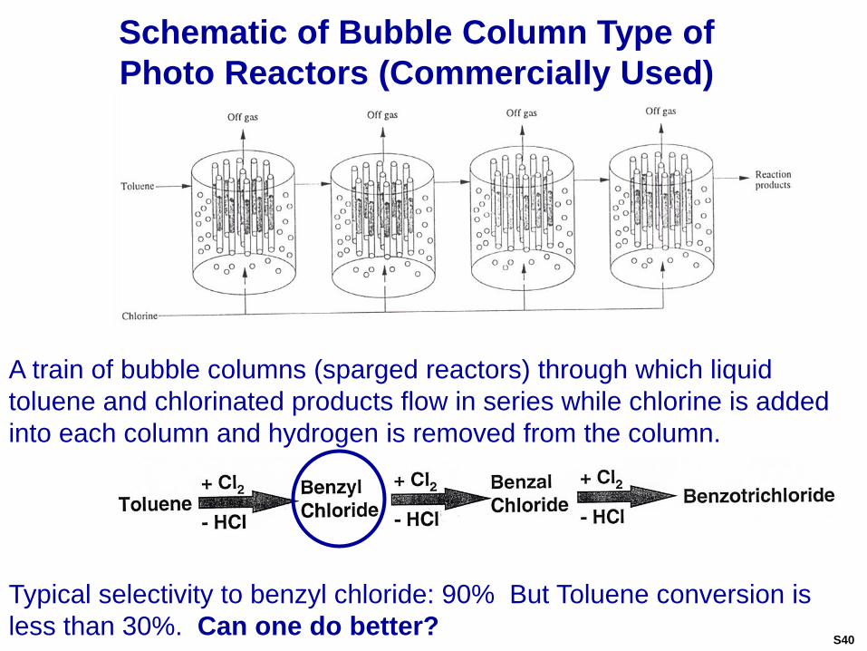
Schematic of Bubble Column Type of
Photo Reactors (Commercially Used)
A train of bubble columns (sparged reactors) through which liquid
toluene and chlorinated products flow in series while chlorine is added
into each column and hydrogen is removed from the column.
Typical selectivity to benzyl chloride: 90% But Toluene conversion is
less than 30%. Can one do better?S40
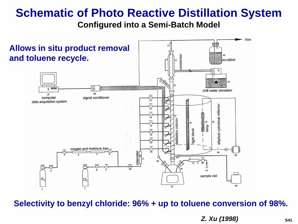
Schematic of Photo Reactive Distillation SystemConfigured into a Semi-Batch Model
Allows in situ product removal
and toluene recycle.
Selectivity to benzyl chloride: 96% + up to toluene conversion of 98%.
Z. Xu (1998) S41
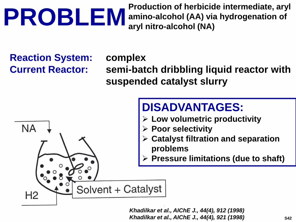
PROBLEMProduction of herbicide intermediate, aryl
amino-alcohol (AA) via hydrogenation of
aryl nitro-alcohol (NA)
Reaction System: complex
Current Reactor: semi-batch dribbling liquid reactor with
suspended catalyst slurry
DISADVANTAGES: Low volumetric productivity
Poor selectivity
Catalyst filtration and separation
problems
Pressure limitations (due to shaft)
Khadilkar et al., AIChE J., 44(4), 912 (1998)
Khadilkar et al., AIChE J., 44(4), 921 (1998) S42
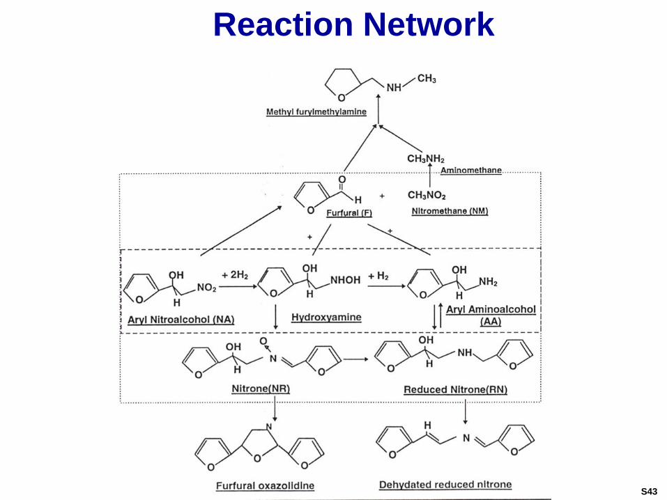
Reaction Network
S43
Conclusions Liquid trickling flow pattern is preferable to a suspended
catalyst mixed slurry to obtain the desired yield and productivity of Amino Alcohol.
Yield improvement is observed with decreasing feed concentration, liquid flow rate and temperature due to suppression of NA decomposition and subsequent side reactions.
Productivity of AA is a complex function of flow, feed concentration and temperature with optimal productivity being determined by the level of acceptable by-product concentrations.
Laboratory trickle bed performance data is shown to be an effective means to obtain the network kinetic parameters by proposing a plausible mechanism and optimizing the reactor model generated data. This is particularly effective in cases where conventional slurry and basked methods are rendered ineffective by the dominance of side reactions.
S44
References
1. Dudukovic, M.P., Larachi, F., Mills, P.L., “Multiphase Reactors – Revisited”, Chem. Eng. Science, 541, 1975-1995 (1999).
2. Dudukovic, M.P., Larachi, F., Mills, P.L., “Multiphase Catalytic Reactors: A Perspective on Current Knowledge and Future Trends”, Catalysis Reviews, 44(11), 123-246 (2002).
3. Levenspiel, Octave, Chemical Reaction Engineering, 3rd
Edition, Wiley, 1999.
4. Tranbouze, P., Euzen, J.P., “Chemical Reactors – From Design to Operation”, IFP Publications, Editions TECHNIP, Paris, France (2002).
S45