Embed Size (px)
Citation preview
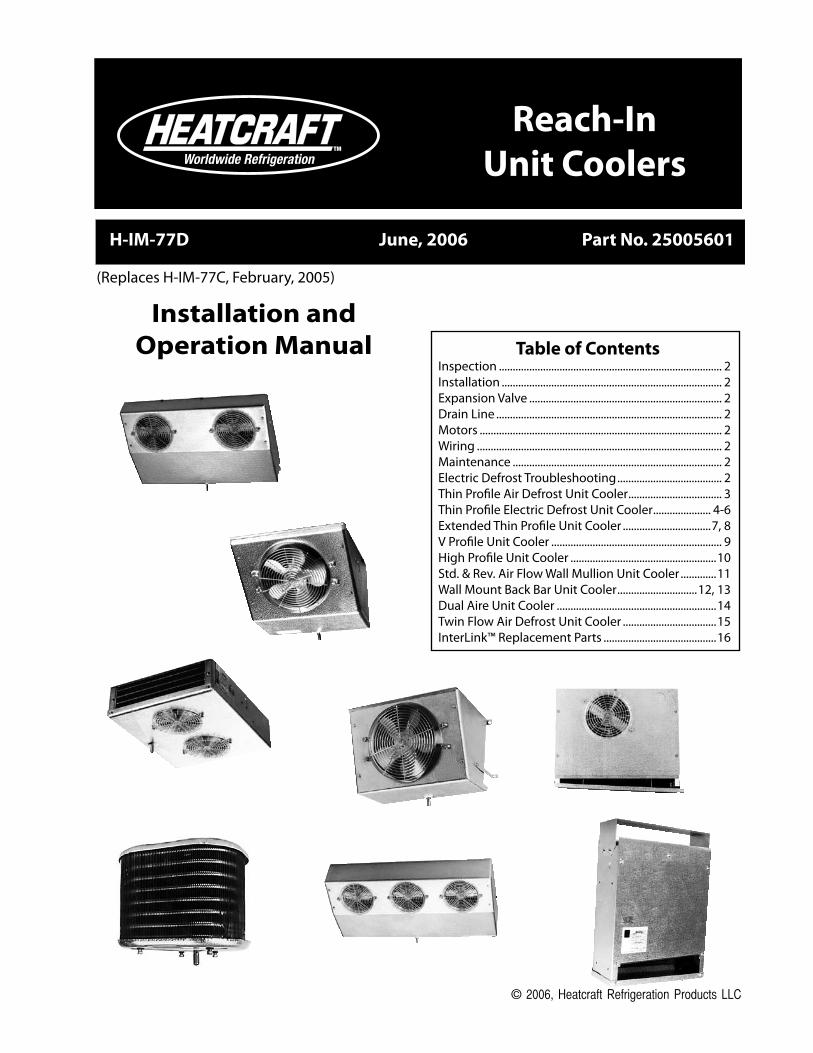
Installation andOperation Manual
Reach-InUnit Coolers
H-IM-77D June, 2006 Part No. 25005601
Table of ContentsInspection.................................................................................. 2Installation................................................................................. 2Expansion.Valve....................................................................... 2Drain.Line................................................................................... 2Motors......................................................................................... 2Wiring.......................................................................................... 2Maintenance............................................................................. 2Electric.Defrost.Troubleshooting....................................... 2Thin.Profile.Air.Defrost.Unit.Cooler................................... 3Thin.Profile.Electric.Defrost.Unit.Cooler...................... 4-6Extended.Thin.Profile.Unit.Cooler.................................7,.8V.Profile.Unit.Cooler............................................................... 9High.Profile.Unit.Cooler......................................................10Std..&.Rev..Air.Flow.Wall.Mullion.Unit.Cooler..............11Wall.Mount.Back.Bar.Unit.Cooler..............................12,.13Dual.Aire.Unit.Cooler...........................................................14Twin.Flow.Air.Defrost.Unit.Cooler...................................15InterLink™.Replacement.Parts..........................................16
(Replaces.H-IM-77C,.February,.2005)
© 2006, Heatcraft Refrigeration Products LLC

2
InspectionWhen.the.equipment.is.received,.all.items.should.be.carefully.checked.against.the.bill.of.lading.to.make.sure.all.crates.and.cartons.have.been.received...All.units.should.be.carefully.inspected.for.hidden.damage.when.received...If.any.damage.is.found,.it.should.be.reported.to.the.carrier.immediately.and.a.claim.should.be.filed...The.unit.nameplate.should.be.checked.to.make.sure.that.the.voltage.agrees.with.the.power.supply.available.
Expansion ValveInstall.expansion.valve.and.feeler.bulb.inside.cabinet.of.the.unit..Recommended.valve.sizes.are.given.for.each.product.family.
Installation
Installation.and.service.of.this.equipment.should.be.performed.only.by.qualified.and.experienced.commercial.refrigeration.mechanics..Correct.application.and.installation.of.this.equipment.is.necessary.to.obtain.optimum.performance.and.customer.satisfaction..Install.all.equipment,.piping.and.electrical.in.accordance.with.local.and.national.codes.and.in.conformance.with.good.practice.required.for.proper.operation..Work.safely!.Prevent.accidents!The.final.step.in.any.installation.is.to.instruct.the.customer.or.user.in.the.operation.of.the.equipment..The.customer.should.be.shown.how.the.equipment.can.be.made.to.operate.properly.and.efficiently..Maintenance.requirements.should.be.explained.
Drain LineAfter.installing.the.fan.panel.assembly,.connect.the.drain.line.to.the.fitting.provided.on.the.unit..A.plastic.hose.or.metal.drain.line.can.be.used.The.drain.line.should.be.pitched.sharply.and.exit.the.cabinet.as.quickly.as.possible..Traps.in.the.drain.line.should.be.located.in.a.warm.ambient.to.prevent.freeze-up.If.only.a.small.portion.of.the.drain.line.is.located.in.the.refrigerated.area,.a.drain.line.heater.will.not.be.required...If.a.drain.line.heater.is.required,.use.approximately.15.watts.per.foot.of.pipe...Connect.the.heater.wire.to.the.terminals.of.the.heater.circuit.(N.and.3).at.the.terminal.block.in.the.junction.box...The.heater.will.then.operate.during.the.defrost.cycle.All.condensate.water.must.be.disposed.of.properly.and.should.not.be.allowed.to.accumulate.or.cause.a.safety.hazard.
General Information
MotorsMotors.are.lifetime.lubricated.and.thermally.protected..Check.an.inoperative.motor.by.disconnecting.and.applying.correct.voltage.across.leads...If.test.fails,.replace.the.motor.
WiringThe.nameplate.on.the.unit.is.marked.with.the.electrical.characteristics.to.be.used.for.wiring.the.unit...The.unit.must.be.grounded..All.wiring.should.be.done.in.accordance.with.applicable.national.and.local.codes.
MaintenancePeriodically.inspect.unit.for.grease.and.soil.accumulation...Clean.with.warm.water.and.soap...Do.not.use.cleaners.containing.ammonia..Inspect.the.drain.pan/fan.panel.occasionally.for.proper.condensate.drainage...Keep.the.drain.opening.clean.
TimerIf.the.system.does.not.go.through.its.proper.sequence.,.check.timer.operation.through.a.defrost.cycle..Check.for.loose.wires.or..terminals..Before.replacing.timer,.check.other.components.
Operation of Paragon TimerTo.set.time.of.day.grasp.knob.which.is.in.the.center.of.the.inner.(fail-safe).dial.and.rotate.it.in.a.counter-clockwise.direction...This.will.cause.the.outer.(24.hour).dial.to.revolve...Line.up.the.correct.time.of.day.on.the.outer.dial.with.the.time.pointer...Do.not.try.to.set.the.time.control.by.grasping.the.other.(24.hour).dial...Place.pins.in.the.outer.dial.at.the.time.of.day.that.defrost.is.required.
Operation of Grasslin TimerTo.set.the.time,.turn.the.minute.hand.clockwise.until.the.time.of.day.(and.AM.or.PM).on.the.outer.dial.is.aligned.with.the.triangle.marker.on.the.inner.dial..Do.not.rotate.minute.hand.counter-clockwise..Move.the.white.tab.(tripper).on.the.outer.dial.outward.at.each.desired.initiation.time..Each.white.tab.(tripper).is.a.15.minute.interval.and.provides.15.minutes.of.defrost..For.longer.defrost.duration,.move.additional.tabs.(following.in.time).from.the.initiation.tab..For.example,.if.a.45.minute.defrost.is.to.start.at.7:00.AM,.move.the.tabs.outward.that.lie.between.7:00.-.7:15,.7:15.-.7:30.and.7:30.-.7:45.on.the.AM.side.of.the.dial..The.defrost.will.initiate.at.7:00.AM.and.time.terminate.at.7:45.AM.(if.temperature.termination.does.not.occur.first).
Fan MotorIf.the.motor.does.not.operate.or.it.cycles.on.thermal.overload,.remove.motor.leads.from.terminal.block.and.apply.correct.voltage.across.the.leads...If.motor.still.does.not.operate.satisfactorily,.it.must.be.replaced...Before.starting.the.unit,.rotate.fan.blades.to.make.sure.they.turn.freely.and.have.sufficient.clearance.
Fan Delay & Defrost Termination ControlThis.control.is.a.single.pole.double.throw.switch...The.red.lead.wire.is.wired.to.common...The.black.wire.is.wired.in.series.with.the.fan.motors...The.brown.wire.is.wired.in.series.with.the.defrost.termination.solenoid.in.the.timer...The.brown.and.red.contacts.close.and.the.black.and.red.contacts.open.when.the.temperature.is.above.55ºF...The.black.and.red.contacts.close.and.the.brown.and.red.contacts.open.when.the.temperature.is.below.35ºF.
On.initial.“pull.down”.of.a.warm.box.the.fan.will.not.start.until.the.coil.temperature.reaches.approximately.35ºF...If.the.box.is.still.comparatively.warm.(60ºF).when.the.fan.starts,.then.blowing.this.warm.air.over.the.coil.may.cause.it.to.warm.up.to.55ºF.and.thus.stop.the.fan...Therefore,.the.fan.may.recycle.on.initial.“pull.down.”..This.control.cannot.be.adjusted.
If.the.fan.motor.fails.to.start.when.the.control.is.below.35ºF,.disconnect.the.fan.motor.leads.and.check.the.motor.as.described.for.fan.motors...Also.check.whether.current.is.being.supplied.at.“N”.and.“4”.from.the.timer...The.fan.delay.control.must.be.below.35ºF.when.checking.for.a.closed.circuit.
Defrost HeaterIf.unit.shows.very.little.or.no.defrosting.and.does.not.heat,.disconnect.heater.and.check.to.find.if.it.is.burned.out...To.test,.apply.correct.voltage.across.heater.or.use.continuity.flashlight.battery.tester.
Drain PanIf.drain.pan.has.an.ice.build-up,.drain.line.may.be.frozen...The.drain.line.should.be.pitched.sharply.and.exit.cabinet.as.quickly.as.possible...Sometimes.location.and.ambient.at.the.drain.outside.of.cabinet.may.cause.freeze-up...A.drain.line.heater.may.be.required.to.correct.the.freeze-up...Any.traps.in.the.drain.line.must.be.located.in.a.warm.ambient.
ELECTRIC DEFROST TROUBLESHOOTING
NOTE: ..Installation.and.maintenance.are.to.be.performed.only.by.qualified.personnel.who.are.familiar.with.local.codes.and.regulations,.and.experienced.with.this.type.of.equipment.
CAUTION: ..Sharp.edges.and.coil.surfaces.are.a.potential.injury.hazard..Avoid.contact..with.them.
WARNING:....Refrigerant.can.be.harmful.if.it.is.inhaled..Refrigerant.must.be.used.and.recovered.responsibly..Failure.to.follow.this.warning.may.result.in.personal.injury.or.death.
WARNING:..All.power.must.be.disconnected.before.cleaning.drain.pan/fan.panel..It.serves.as.a.cover.of.hazardous.moving.parts..Operation.of.unit.without.pan.in.place.constitutes.a.hazard.
NOTE: After.correcting.faulty.condition.it.is.essential.that.the.coil.and.unit.be.free.of.ice.before.placing.unit.back.on.automatic.operation.
�
Description All Sizes Part Number 115V Motor 25�00701 208/2�0V Motor 25�00801 Fan Blade 5101B Fan Guard 5054D Motor Mount 91179001
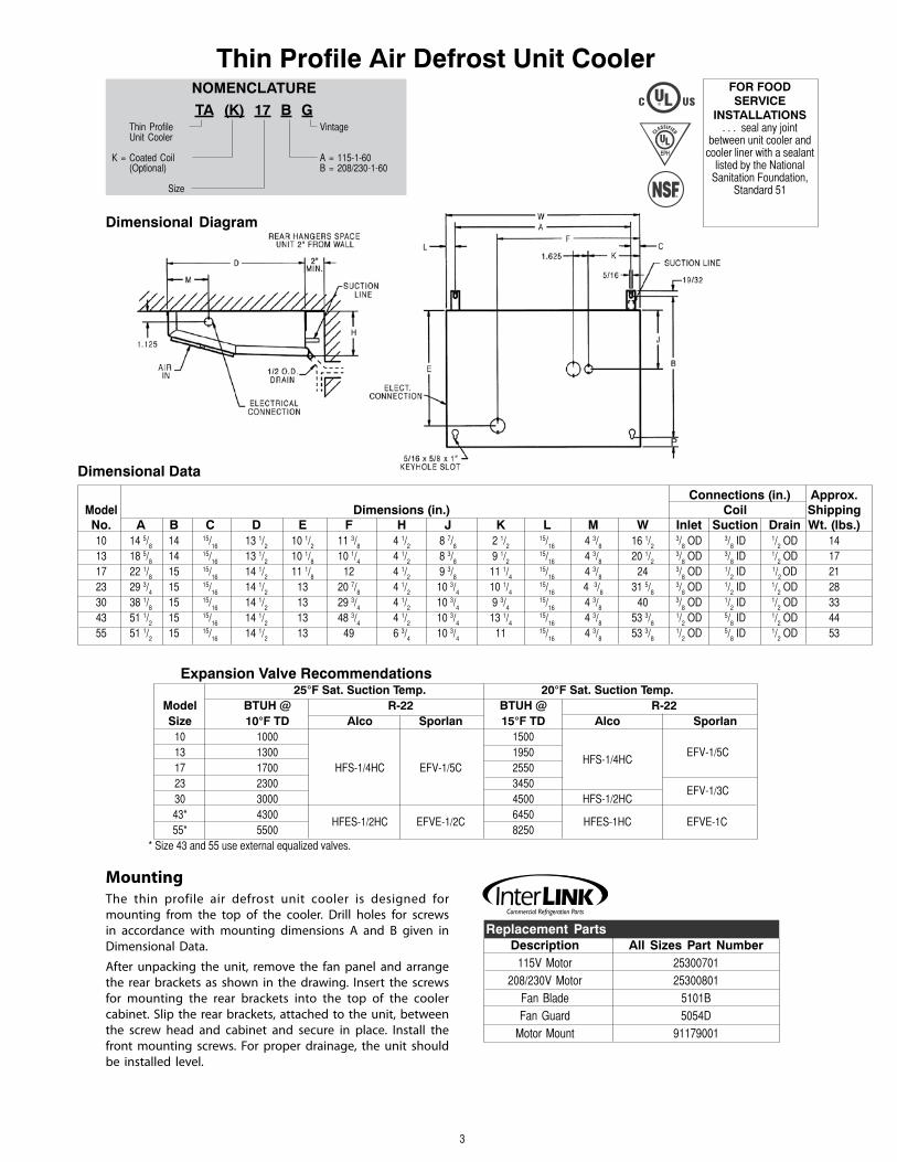
Thin Profile Air Defrost Unit Cooler
MountingThe. thin. profile. air. defrost. unit. cooler. is. designed. for.mounting. from. the. top. of. the. cooler.. Drill. holes. for. screws.in. accordance. with. mounting. dimensions. A. and. B. given. in.Dimensional. Data.
After. unpacking. the. unit,. remove. the. fan. panel. and. arrange.the. rear. brackets. as. shown. in. the. drawing.. Insert. the. screws.for. mounting. the. rear. brackets. into. the. top. of. the. cooler.cabinet.. Slip. the. rear. brackets,. attached. to. the. unit,. between.the. screw. head. and. cabinet. and. secure. in. place.. Install. the.front. mounting. screws.. For. proper. drainage,. the. unit. should.be. installed. level.
Connections (in.) Approx. Model Dimensions (in.) Coil Shipping No. A B C D E F H J K L M W Inlet Suction Drain Wt. (lbs.) 10 14 5/
8 14 15/
16 1� 1/
2 10 1/
2 11 �/
8 4 1/
2 8 7/
8 2 1/
2 15/
16 4 �/
8 16 1/
2 �/
8 OD �/
8 ID 1/
2 OD 14
1� 18 5/8
14 15/16
1� 1/2 10 1/
8 10 1/
4 4 1/
2 8 �/
8 9 1/
2 15/
16 4 �/
8 20 1/
2 �/
8 OD �/
8 ID 1/
2 OD 17
17 22 1/8 15 15/
16 14 1/
2 11 1/
8 12 4 1/
2 9 �/
8 11 1/
4 15/
16 4 �/
8 24 �/
8 OD 1/
2 ID 1/
2 OD 21
2� 29 �/4 15 15/
16 14 1/
2 1� 20 7/
8 4 1/
2 10 �/
4 10 1/
4 15/
16 4 �/
8 �1 5/
8 �/
8 OD 1/
2 ID 1/
2 OD 28
�0 �8 1/8 15 15/
16 14 1/
2 1� 29 �/
4 4 1/
2 10 �/
4 9 �/
4 15/
16 4 �/
8 40 �/
8 OD 1/
2 ID 1/
2 OD ��
4� 51 1/2 15 15/
16 14 1/
2 1� 48 �/
4 4 1/
2 10 �/
4 1� 1/
4 15/
16 4 �/
8 5� �/
8 1/
2 OD 5/
8 ID 1/
2 OD 44
55 51 1/2 15 15/
16 14 1/
2 1� 49 6 �/
4 10 �/
4 11 15/
16 4 �/
8 5� �/
8 1/
2 OD 5/
8 ID 1/
2 OD 5�
Dimensional Data
Dimensional Diagram
Thin Profile Vintage Unit Cooler
K = Coated Coil A = 115-1-60 (Optional) B = 208/2�0-1-60
Size
NOMENCLATURETA (K) 17 B G
Expansion Valve Recommendations 25°F Sat. Suction Temp. 20°F Sat. Suction Temp. Model BTUH @ R-22 BTUH @ R-22 Size 10°F TD Alco Sporlan 15°F TD Alco Sporlan 10 1000 1500 1� 1�00 1950
HFS-1/4HC EFV-1/5C
17 1700 HFS-1/4HC EFV-1/5C 2550 2� 2�00 �450
EFV-1/�C �0 �000 4500 HFS-1/2HC 4�* 4�00
HFES-1/2HC EFVE-1/2C 6450
HFES-1HC EFVE-1C
55* 5500 8250 * Size 4� and 55 use external equalized valves.
FOR FOOD SERVICE
INSTALLATIONS. . . seal any joint
between unit cooler and cooler liner with a sealant
listed by the National Sanitation Foundation,
Standard 51
Replacement PartsCommercial Refrigeration Parts

4
Expansion Valve Recommendations
-10°F. Suction 10° TD -15°F. Suction 15° TD Model BTUH R-404 BTUH R-404A Size 10° TD Alco Sporlan 15° TD Alco Sporlan 09 900 1�50
12 1200 HFS1/8SZ EFS1/
8Z 1800 HFS1/
8SZ EFS1/
8Z
16 1600 2400
21 2100 �150 HFS1/4SZ EFS1/
6Z
28 2800 HFS1/4SZ EFS1/
6Z 4200 HFS1/
2SZ EFS1/
4Z
�5* �500 HFES1/4SZ EFSE1/
4Z 5250 HFES1/
2SZ EFSE1/
2Z
5�* 5�00 HFES1/2SZ EFSE1/
2Z 7950 HFES1SZ EFSE1Z
*Sizes �5 and 5� use external equalized valves.
Dimensional Diagram
Thin Profile Electric Defrost Unit Cooler
MountingThis.unit.cooler.is.designed.for.mounting.from.the.top.of.the.cooler..Drill.holes.for.screws.in.accordance.with.mounting.dimensions.given. in.Dimensional.Diagram.and.Data.
After. unpacking. the. unit,. remove. the. fan. panel. and. arrange. the. rear. brackets. as. shown. in. the. drawing.. Insert. the. screws. for.mounting.the.rear.brackets.into.the.top.of.the.cooler.cabinet..Slip.the.rear.brackets,.attached.to.the.unit,.between.the.screw.head.and.cabinet.and.secure. in.place.. Install. the. front.mounting. screws..For.proper.drainage,. the.unit. should.be. installed. level.
Thin Profile Vintage Electric Defrost
Size A = 115-1-60 B = 208/2�0-1-60
NOMENCLATURE
TL 12 A G
Dimensional Data Connections (In.) Approx. Dimensions (In.) Coil Ship Wt. Size A B C D E F H J K L M N W Inlet Suction Drain (Lbs.) 09 145/
8 14 15/
16 1�1/
2 101/
2 11�/
8 41/
2 87/
8 21/
2 15/
16 4�/
8 - 161/
2 �/
8 OD �/
8 ID 1/
2 OD 14
12 185/8 14 15/
16 1�1/
2 101/
8 101/
4 41/
2 8�/
8 91/
2 15/
16 4�/
8 - 201/
2 �/
8 OD 1/
2 ID 1/
2 OD 19
16 221/8 15 15/
16 141/
2 111/
8 12 41/
2 9�/
8 111/
4 15/
16 4�/
8 - 24 �/
8 OD 1/
2 ID 1/
2 OD 2�
21 221/8 161/
2 15/
16 161/
2 141/
2 187/
8 6�/
4 117/
8 171/
4 15/
16 4�/
8 - 24 �/
8 OD 1/
2 ID 1/
2 OD 24
28 29�/4 15 15/
16 141/
2 1� 20�/
4 6�/
4 9�/
4 97/
8 15/
16 4�/
8 - �15/
8 �/
8 OD 1/
2 ID 1/
2 OD 27
�5 �5�/4 161/
2 15/
16 161/
2 141/
2 ��1/
4 6�/
4 115/
8 18�/
8 15/
16 6” 51/
8 �8�/
8 1/
2 OD 5/
8 ID 1/
2 OD �8
5� 461/2 161/
2 11/
8 161/
2 141/
2 44 6�/
4 115/
8 �0�/
8 11/
2 6” 51/
8 491/
8 1/
2 OD 7/
8 ID 1/
2 OD 5�
FOR FOOD SERVICE
INSTALLATIONS. . . seal any joint
between unit cooler and cooler liner with a sealant
listed by the National Sanitation Foundation,
Standard 51

5
Motor Heater Model No. of Amps. Amps. Size Motors A* B* A* B* 09 1 0.8 0.4 4.1� 2.07 12 2 1.6 0.8 5.22 2.61 16 2 1.6 0.8 6.09 �.04 21 1 1.0 0.5 9.57 4.78 28 � - 1.2 - 5.7 �5 2 - 1.0 - 7.0 5� � - 1.5 - 8.5
Part 115 Volt 208-230 Volt Description 09 12 16 21 09 12 16 21 28 35 53
Motor 25�00701 25�00701 25�00701 25�0�201 25�00801 25�00801 25�00801 25�0��01 25�00801 25�0��01 25�0��01 Fan Blade 5101B 5101B 5101B 2�100201 5101B 5101B 5101B 2�100201 5101B 2�100201 2�100201 Fan Guard 5054D 5054D 5054D H50�28 5054D 5054D 5054D H50�28 5054D H50�28 H50�28 Heater 45�9N 4540N 4541N 4545N 4542N 454�N 4544N 4546N H50097 24700701 24700702 Heater Clip 554�J 554�J 554�J 554�J 554�J 554�J 554�J 554�J H500�9 554�J 554�J Defrost Control 5709L 5709L 5709L 5709L 5709L 5709L 5709L 5709L 5709L 5709L 5709L Mount 91179001 91179001 91179001 2�101401 91179001 91179001 91179001 2�101401 91179001 2�101401 2�101401
Step “A” - Normal Refrigeration Cycle1.. Power.is.supplied.to.N.and.4.terminals.by.the.timer.2.. The.fan.delay.and.defrost.termination.thermostat.is.closed.in.the... fan.delay.position.and.open.in.the.defrost.termination.position.3.. The.defrost.heater.is.off.4.. The.compressor.operates.in.accordance.with.the.demands.of.the... refrigeration.system.temperature.and/or.pressure.controls.5.. The.unit.cooler.fan.operates.continually.6.. Frost.builds.up.slowly.on.the.evaporator.
Step “B” - Defrost Cycle1.. Defrosting.of.the.evaporator.is.started.automatically.by.the.timer... at.predetermined.times.-.typical.settings.of.the.timer.would.be.1.to... 3.defrost.periods.per.24.hours.2.. The.timer.mechanically.opens.switch.“A”.which.breaks.the.circuit.to... the.compressor.and.evaporator.fan.motors,.thereby.shutting.them... off,.and.closes.switch.“B,”.thereby.permitting.current.to.flow.to... the.heater.3.. The.heater.recessed.in.slots,.gives.up.heat.directly.to.the.fins.of.the... evaporator...This.heat.raises.coil.and.refrigerant.temperature.... to.32ºF.causing.the.frost.to.melt.4.. Frost.on.the.evaporator.is.melted.and.defrost.water.drips.into.the... heated.drain.pan.and.flows.down.the.drain.5.. When.frost.has.completely.melted.from.the.coil,.the.coil.starts.to... warm.up.beyond.32ºF.
Step “C” - Coil Re-Cooling Cycle1.. When.the.coil.warms.up.to.55ºF,.the.defrost.termination.thermostat... closes.which.allows.the.current.to.flow.to.the.solenoid.in.the.timer,... which.then.energizes.and.trips.the.timer.switch.back.to.its.normal... position.(switch.“A”.closed,.switch.“B”.open)..The.fan.delay.portion... of.this.thermostat.is.now.open.
2.. The.compressor.now.starts.3.. Then.fan.motors.remain.off.because.the.fan.delay.thermostat.is... open..This.prevents.warm.air.from.being.blown.into.the.. .. refrigerated.space.4.. The.evaporator.coil.cools.down.approaching.operating.. .. temperature..Superheated.gas.only.passes.to.the.compressor.
Step “D” - Return to NormalRefrigeration Operation1.. When.the.coil.temperature.reaches.35ºF,.the.fan.control.switch... closes...This.allows.current.to.flow.to.the.fan.motor.and.the.unit.is... now.back.in.operation.as.in.Step.“A.”
IMPORTANT1.. On.initial.“pull.down”.of.a.warm.box,.the.fan.will.not.start.until.coil... temperature.reaches.approximately.35ºF..If.box.is.still.. .. comparatively.warm.(60ºF).when.the.fan.starts,.then.blowing.this... warm.air.over.the.coil.may.cause.it.to.warm.up.to.55ºF.and.thus... stop.the.fan..Therefore,.fan.may.recycle.several.times.on.initial... “pull.down.”2.. The.timer.has.an.adjustable.fail-safe.feature.which.will.return.the... system.to.the.refrigeration.cycle.at.the.end.of.a.predetermined... time.(factory.set.at.24.minutes).if.automatic.control.devices.fail.3.. Frequent.defrost.periods.are.not.necessary!.The.determining.factor... for.number.of.defrosts.per.day.is.the.frost.load..When.frost.“build-.. up”.results.in.a.loss.of.refrigeration.capacity,.then.a.defrost.is.... required...One.to.three.defrosts.per.day.are.recommended.4.. A.low.temperature.thermostatic.expansion.valve.with.pressure... limiting.feature.is.desirable.for.use.with.these.units..Such.a.valve... prevents.feeding.of.refrigerant.to.the.coil.during.the.defrost.cycle.
Sequence of Operation
Typical Wiring Diagram for Thin Profile Electric Defrost Unit Cooler
1.. Use.copper.conductors.only.2.. Unit.must.be.grounded.3.. Timer-Paragon.Model.8145-20.may.be.factory.supplied,. field.installed,.or.field.supplied.and.installed.4.. Fan.delay.and.defrost.termination.-.Red.to.N,.Brown.to.X,. Black.to.F...Fans.will.not.operate.until.thermostat.resets.5.. Heater.limit:..Red.to.N,.White.to.H.omitted.on.model.28;. heater.is.connected.directly.to.N.6.. *Indicates.electrical.code:.A=115/60/1,.B=208-230/60/1.Commercial Refrigeration Parts
Replacement Parts

6
Typical System Wiring Diagram with Thin Profile Electric Defrost Unit Cooler

7
FOR FOOD SERVICE
INSTALLATIONS. . . seal any joint
between unit cooler and cooler liner with a sealant
listed by the National Sanitation Foundation,
Standard 51
NOMENCLATURELT A 053 A A
Vintage
A = Air Defrost A = 115-1-60 L = Electric Defrost B = 208/2�0-1-60
Size
Extended Thin Profile Unit Cooler
Dimensional Diagram
ExtendedThin ProfileUnit Cooler
Connections- Electric Defrost
Nozzle Selection- Electric Defrost
Air Electric Number Dimensions (Inches / mm) Defrost Defrost of A B C D LTA LTL Fans Inches mm Inches mm Inches mm Inches mm 05� 046 2 49 �/8 1254 40 7/8 10�8 --- --- --- --- 079 068 � 69 1/8 1756 60 5/8 1540 --- --- --- --- 102 09� 4 88 7/8 2257 80 �/8 2042 40 7/8 10�8 --- --- 1�4 115 5 108 5/8 2759 100 1/8 254� 40 7/8 10�8 --- --- 172 1�� 6 128 �/8 �261 119 7/8 �045 40 7/8 10�8 �9 1/2 100�
Number Connections (Inches) Net Model of Coil External Weight Size Fans Inlet Suction Equalizer Drain (Lbs.) LTA 05� 2 1/2 OD 5/8 ID 1/4 �/4 MPT 48 LTA 079 � 1/2 OD 5/8 ID 1/4 �/4 MPT 69 LTA 102 4 1/2 OD 7/8 ID 1/4 �/4 MPT 85 LTA 1�4 5 1/2 OD 7/8 ID 1/4 �/4 MPT 108 LTA 172 6 1/2 OD 1 1/8 ID 1/4 �/4 MPT 124
Number Connections (Inches) Net Model of Coil External Weight Size Fans Inlet Suction Equalizer Drain (Lbs.) LTL 046 2 1/2 OD 5/8 ID 1/4 �/4 MPT 48 LTL 068 � 1/2 OD 5/8 ID 1/4 �/4 MPT 69 LTL 09� 4 1/2 OD 7/8 ID 1/4 �/4 MPT 85 LTL 115 5 1/2 OD 7/8 ID 1/4 �/4 MPT 108 LTL 1�� 6 1/2 OD 1 1/8 ID 1/4 �/4 MPT 124
Number Air Distributor Tube Number of Defrost OD Length of Fans LTA (Inches) (Inches) Circuits R404A R22 2 05� �/16 21 1/2 2 L-1/2 L-1/� � 079 �/16 21 1/2 2 L-1/2 L-1/� 4 102 �/16 21 1/2 4 L-�/4 L-1/2 5 1�4 �/16 21 1/2 4 L-1 L-�/4 6 172 �/16 21 1/2 5 L-1 1/2 L-1
Number Electric Distributor Tube Number Low Temp. Medium Temp. of Defrost OD Length of -30ºF to 0ºF SST +10ºF to +25ºF SST Fans LTL (Inches) (Inches) Circuits R404A R22 R404A R22 2 046 �/16 21 1/2 � L-�/4 L-1/2 L-1/2 L-1/� � 068 �/16 21 1/2 � L-�/4 L-1/2 L-�/4 L-1/2 4 09� �/16 21 1/2 5 L-1 L-�/4 L-1 L-�/4 5 115 �/16 21 1/2 5 L-1 1/2 L-1 L-1 L-�/4 6 1�� �/16 21 1/2 5 L-1 1/2 L-1 L-1 1/2 L-1
Dimensional Data
Connections- Air Defrost
Nozzle Selection- Air Defrost

8
Extended Thin Profile Unit Cooler (continued)
Motor / Fan Blade / Fan Guard
Defrost Heater
Cabinet Components
Electrical ComponentsDrain Fitting
MountingThis. unit.cooler. is.designed. for. mounting. from.the. top.of. the.cooler..Drill.holes. for. screws. in.accordance. with.mounting.dimensions.given. in.Dimensional. Diagram.and.Data.
After. unpacking. the.unit,.arrange. the.unit.7.1/2”. from.wall..Insert. the.screws. for.mounting. the. rear. brackets. into. the. top.of.the. cooler.cabinet..Slip. the. rear. brackets,. attached. to. the.unit,.between. the.screw.head.and.cabinet.and.secure. in.place.. Install.the. front.mounting.screws..For. proper. drainage,. the.unit. should.be. installed. level.
Coils
Coils Coils
Wiring Diagram
Part# Description Voltage No.Fans 24723002 DefrostHeater1100W230V 208-230/1/60 2 24723003 DefrostHeater1650W230V 208-230/1/60 3 24723004 DefrostHeater2200W230V 208-230/1/60 4 24723005 DefrostHeater2750W230V 208-230/1/60 5 24723006 DefrostHeater3300W230V 208-230/1/60 6 23305501 HeaterClip N/A 3-7
Part# Description 25315501 Motor115/1/60ShadedPole 25315601 Motor208-230/1/60ShadedPole 22919001 FanBlade10” 23105001 FanGuard-Wire 23105101 MotorMount
Part# Description No.Fans 40970201 DrainPan 2 40970301 DrainPan 3 40970401 DrainPan 4 40970501 DrainPan 5 40970601 DrainPan 6 46834201 FanPanel-2Fan 2,4,5 46834301 FanPanel-3Fan 3,5,6 46844201 BeaconFanPanel-2Fan 2,4,5 46844301 BeaconFanPanel-3Fan 3,6 40931201 Panel-SideRight(PipingEnd) N/A 40931301 Panel-FrontAccessRight(PipingEnd) N/A 40930901 Panel-SideLeft(ElectricalEnd) N/A 40931001 Panel-FrontAccessLeft(ElectricalEnd) N/A 40931401 Panel-BackRight(PipingEnd) N/A 40931101 Panel-BackLeft(ElectricalEnd) N/A 40931601 Panel-BeaconAccess N/A
Part# Description 4145W TerminalStrip-ElectricDefrostModels 5709L DefrostTerminationThermostat-sealedbimetaltype 5709L FanDelayThermostat-sealedbimetaltype 2891040 RoomThermostat 5708L HeaterLimitThermostat-sealedbimetaltype
Part# Description 26925101 DrainFittingAssembly
Commercial Refrigeration Parts
Replacement Parts

9
V Profile Unit Cooler
Dimensional Diagram
Mounting
The.V.profile.unit.cooler. is.designed. for.mounting. from.the. top.or. the.back.wall.of.the.cooler..Drill.holes.for.screws.in.accordance.with.mount-ing. dimensions. given. in. Dimensional. Data.
After.unpacking.the.unit,.secure.top.of.unit.to.ceiling.or.back.wall.and.arrange. the. rear. brackets. as. shown. in. the. drawing.. Mount. the. rear.brackets. to. wall,. if. applicable,. to. the. installation.
For. proper. drainage,. the. unit. should. be. installed. level.
V Profile Models Description 06, 08, 12 17
115V Motor 25�00701 25�0�201 208/2�0V Motor 25�00801 25�0��01 Fan Blade 5101B 2�100201 Fan Guard 5054D H50�28 Motor Mount 91179001 2�101401
Expansion Valve Recommendations V 25°F. Evaporating Temp. 20°F. Evaporating Temp. Profile BTUH @ R-22 BTUH @ R-22 Model 10°F. TD Alco Sporlan 15°F. TD Alco Sporlan 06 600 900
08 800 HFS 1/4 HC EFV 1/
5 C 1200 HFS 1/
4 HC EFV 1/
5 C
12 1200 1800
17 1700 2550
Dimensional Data V Connections (In.) Approx. Profile Dimensions (In.) Coil Ship Wt. Model A B C D E F H J K W Inlet Suction Drain (Lbs.)
06 4 5/16
1� 1/4 4 5/
16 - - � �/
8 6 7/
8 5 1/
4 8 1/
8 12 1/
2 �/
8 OD �/
8 ID 1/
2 OD 9
08 4 5/16
1� 1/4 4 5/
16 - - � �/
8 6 7/
8 5 1/
4 8 1/
8 12 1/
4 �/
8 OD �/
8 ID 1/
2 OD 9
12 4 1/2 18 �/
4 5 5/
16 - - � �/
8 8 4 7/
8 8 1/
8 18 �/
8 OD �/
8 ID 1/
2 OD 14
17 5 1/4
14 �/4
5 1/4 9 2 1/
2 4 9 �/
4 6 1�/
16 10 1/
2 14 �/
8 OD �/
8 ID 1/
2 OD 11
NOMENCLATUREVA (K) 08 A G
V Profile Vintage Unit Cooler A = 115-1-60K = Coated Coil B = 208/2�0-1-60 (Optional) Size
FOR FOOD SERVICE
INSTALLATIONS. . . seal any joint
between unit cooler and cooler liner with a sealant
listed by the National Sanitation Foundation,
Standard 51
Commercial Refrigeration Parts
Replacement Parts

10
Dimensional Data Connections (In.) Approx. Model Dimensions (In.) Coil Ship Wt. No. A B C D W Inlet Suction Drain (Lbs.) 1� 12 5/
8 12 �/
8 11 7/
16 1 �/
8 14 1/
4 �/
8 OD �/
8 ID 1/
2 OD 16
17 15 5/8 12 �/
8 14 7/
16 1 �/
8 17 1/
4 �/
8 OD 1/
2 ID 1/
2 OD 17
2� 21 5/8 12 �/
8 21 1/
16 7/
8 22 �/
4 �/
8 OD 1/
2 ID 1/
2 OD 22
�0 26 1/8 12 �/
8 25 1�/
16 1 27 �/
4 �/
8 OD 1/
2 ID 1/
2 OD 27
4� �6 5/16
- - - �8 1/2 OD 1/
2 ID 1/
2 OD 40
High Profile Unit Cooler
Dimensional Diagram
MountingUsing.dimensions.given.in.Dimensional.Diagram.and.Data,.install.mounting. screws. for. rear. hangers. and. slide. hanger. slots. onto.screws.before.tightening..Open.cabinet.and.install.screws.through.top,. front. mounting. holes. to. ceiling. of. box.
Expansion Valve Recommendations 25°F Sat. Suction Temp. 20°F Sat. Suction Temp. Model BTUH @ R-22 BTUH @ R-22 Size 10°F TD Alco Sporlan 15°F TD Alco Sporlan 1� 1�00 1950
EFV-1/5C
17 1700 HFS-1/4HC EFV-1/5C
2550 HFS-1/4HC 2� 2�00 �450
EFV-1/�C
�0 �000 4500 HFS-1/2HC 4�* 4�00 HFES-1/2HC EFVE-1/2C 6450 HFES-1HC EFVE-1C * Size 4� uses external equalized valve.
Description All Sizes Part Number 115V Motor 25�0�201 208/2�0V Motor 25�0��01 Fan Blade 2�100201 Fan Guard H50�28 Motor Mount 2�101401
FOR FOOD SERVICE
INSTALLATIONS. . . seal any joint
between unit cooler and cooler liner with a sealant
listed by the National Sanitation Foundation,
Standard 51
High Profile Vintage Unit Cooler
K = Coated Coil A = 115-1-60 (Optional) B = 208/2�0-1-60
Size
NOMENCLATUREC (K) 43 B G
Commercial Refrigeration Parts
Replacement Parts

11
Standard or Connections (In.) Approx. Reverse Flow Dimensions (In.) Coil Shipping Models H L M W Inlet Suction Drain Wt. (Lbs.) 1� 17 �/
4 16 7/
8 12 1/
4 15 5/
8 �/
8 OD �/
8 OD 5/
8 OD 19
17 19 �/4 16 7/
8 14 1/
4 15 5/
8 �/
8 OD �/
8 OD 5/
8 OD 20
2� 19 �/4 2� 1/
4 14 1/
4 22 �/
8 OD 1/
2 OD 5/
8 OD 28
MountingThe. standard. flow. mullion. unit. draws. air. in. at. the. top. and.discharges.out.the.bottom..The.reverse.flow.mullion.draws.air.in.at.the.bottom.and.discharges.out.the.top...The.unit.may.be.mounted.in.a.mullion.or.against.a.back.or.side.wall.
When.mounting.to.the.mullion.of.under.counter.refrigerators,.mounting.holes.are.located.on.both.ends.of.the.unit.for.attaching.to.“customer.furnished”.mounting.brackets.
When.wall.mounted,.four.“L”.type.brackets.and.eight.stainless.steel.sheet.metal.screws.are.provided.to.attach.the.brackets.to.side.panels.
IMPORTANT: A minimum of 2 inches must be provided between the top of the unit and the top of the cabinet.
Standard & Reverse Air Flow Wall Mullion Unit Cooler
Dimensional Data
25°F Sat. Suction Temp. 20°F Sat. Suction Temp. Model BTUH @ R-22 BTUH @ R-22 Size 10°F TD Alco Sporlan 15°F TD Alco Sporlan 1� 1�00 1950
17 1700 HFS-1/4HC EFV-1/5C 2550 HFS-1/4HC
2� 2�00 �450
Expansion Valve Recommendations
Part Standard Reverse Description Down Flow Up Flow 115V Motor 25�00701 25�00701 208/2�0V Motor 25�00801 25�00801 Fan Blade 5102C 5117C Fan Guard (1�-17) 5076E 5076E Fan Guard (2�) 5077E 5077E Motor Mount 91179001 91179001 Drain Pan (1�-17) 74422002 74422002 Drain Pan (2�) 744�6002 744�6002
FOR FOOD SERVICE
INSTALLATIONS. . . seal any joint
between unit cooler and cooler liner with a sealant
listed by the National Sanitation Foundation,
Standard 51
A.top.barrier.is.supplied.and.must.be.used.if.combustible.material..is.above.the.unit..On.reverse.flow.models.the.barrier.may.be.used.to.direct.the.air.straight.out.or.up.at.a.45°.angle..Holes.and.slots.are.provided.to.adjust.the.barrier..If.noncombustible.material.is.used.above.the.unit,.the.barrier.may.be.discarded.if.desired.
Knockouts.are.provided.for.bringing.the.refrigerant.piping.through.either.end.of.the.cabinet..An.electrical.knockout.is.provided.into.an.internal.junction.box.
Dimensional Diagram
NOMENCLATURE
XXX K 13 A GKM = Standard Vintage Air FlowRAM=Reverse Air Flow A = 115-1-60 K = Coated Coil B = 208/2�0-1-60 Size
EFV-1/�C
EFV-1/5C
Replacement PartsCommercial Refrigeration Parts
12
Wall Mount Back Bar Unit Cooler
Dimensional Diagram
MountingThe.Wall.Mount.Back.Bar.Unit.Cooler.is.a.low.height.unit.designed.for.undercounter.applications..Air.is.drawn.in.at.the.bottom.of.the.unit.and.discharged.out.the.front..Two.mounting.angles.are.included.with.the.unit.and.should.be.installed.to.space.the.unit.3/4”.off.the.wall..Air.deflector(s).are.included.and.can.be.mounted.over.the.top.half.of.the.fan.guard.to.direct.the.air.up..The.deflector.may.be.left.off.if.total.horizontal.air.movement.is.desired..If.used,.the.deflector.can.be.field.formed.to.direct.the.air.where.needed..Locating.holes.and.screws.are.provided.
Dimensional Data Approx. Model BTUH Motor Data Dimensions (In.) Ship Wt. BB 10°F TD CFM Qty. HP W A B C D E F (Lbs.) L10 1,000 90 1 1/150 19�/
4 191/
8 18 171/
2 71/
16 - 165/
8 17
M11 1,100 90 1 1/150 19�/4 191/
8 18 171/
2 71/
16 - 165/
8 16
L15 1,500 180 2 1/150 261/4 255/
8 241/
2 24 41�/
16 85/
8 2�1/
8 20
M16 1,600 180 2 1/150 261/4 255/
8 241/
2 24 41�/
16 85/
8 2�1/
8 19
Low -10°F Sat. Suction Temp. -15°F Sat. Suction Temp. Temp BTUH @ R-404A BTUH @ R-404A Model 10°F TD Alco Sporlan 15°F TD Alco Sporlan BBL10 1000
HFS-1/8SZ EFS-1/8Z 1500 HFS-1/8SZ EFS-1/8Z
BBL15 1500 2250 HFS-1/4SZ EFS-1/6Z Med 25°F Sat. Suction Temp. 20°F Sat. Suction Temp. Temp BTUH @ R-22 BTUH @ R-22 Model 10°F TD Alco Sporlan 15°F TD Alco Sporlan BBM11 1100
HFS-1/4HC EFV-1/5C 1870
HFS-1/4HC EFV-1/5C
BBM16 1600 2720
Expansion Valve Recommendations
Description All Sizes Part No. 115V Motor 25�00701 208/2�0V Motor 25�00801 Fan Blade 5101B Fan Guard 5054D Motor Mount 91179001
NOMENCLATUREBB L S 10 A G
A = 115-1-60B = 208/2�0-1-60
RevisionBack Bar Unit Cooler
L = Low Temp UnitM = Med. Temp Unit
SizeBlank = Std. Unit
S = Slave UnitM = Master Unit
FOR FOOD SERVICE
INSTALLATIONS. . . seal any joint
between unit cooler and cooler liner with a sealant
listed by the National Sanitation Foundation,
Standard 51
NOTE: All units have �/8 O.D. suction, 1/2 O.D. sweat inlet connection and 1/2 O.D. drain.
Commercial Refrigeration Parts
Replacement Parts

1�
Air Defrost Wiring, Model BBM
Electric Defrost Wiring, Model BBL

14
Dual Aire Unit Cooler
Recognized ComponentUnderwriter’s Lab., Inc.
FOR FOODSERVICE
INSTALLATIONS. . . seal any joint
between unit coolerand cooler linerwith a sealantlisted by the
National SanitationFoundation,Standard 51
Mounting1.. Drill. holes. in. ceiling. or. backwall. and. insert. #10. screws. to.
within.1/16”.of.surface.2.. Attach.expansion.valve.drip.pan.to.drain.pan.of.unit.3.. Check.all.screws.for.tightness.. .4.. Hang. unit. using. keyhole. slots,. adjusting. mounting. screws.
as.necessary..Tighten.screws.from.inside.of.cabinet..Remove.drain.pan.to.reach.screws.
WARNING:All.power.must.be.disconnected.before.cleaning.drain.pan..It.also.serves.as.cover.of.hazardous.moving.parts,.and.operation.of.unit.without.pan.in.place.constitutes.a.hazard.
Dimensional Diagram
Expansion Valve Recommendations
NOMENCLATURE
U K 009 0 B
U - Dual AireK - Coated Coil
Size
Design Revision
0 = 115/60/11 = 208-2�0/60/1A = 110/50/1C = 220/50/1
Replacement Part for Size: Description 009 012 015
Drain Pan 66974002 66958002 66980002
Valve Drip Pan 66982001 66982001 66982001
Fan Panel 66970001 66956001 66976001
Motor (115/1) 5025S 5025S 5026S
(208-2�0/1) 5026T 5026T 5026T
Top Panel 6697�001 66957001 66979001
Fan (115/1) 5124A 5126A 5127A
(208-2�0/1) 92726001 92726002 5127A
Motor Mount 91746001 91746001 91746001
*Optionally available are molded harness for motor connection in the following lengths:
�0” (4�18K001)48” (4�18K002)
Models H W D A B C Inlet Suction Drain (Lbs.)
009 8 1/2 11 1/
2 8 7/
8 6 4 � 1/
2 1/
2 FN �/
8 ID 1/
2 OD 8
012 8 1/2 17 1/
2 8 7/
8 12 4 9 1/
2 1/
2 FN �/
8 ID 1/
2 OD 10
015 9 1/2 17 1/
2 10 7/
8 12 4 9 1/
2 1/
2 FN �/
8 ID 1/
2 OD 12
Approx. Dual Aire Dimensions (In.) Coil Ship Wt.
Dimensional DataConnections (In.)
Commercial Refrigeration Parts
Replacement Parts
Model.Size
25°F.Sat..Suction.Temp. 20°[email protected]°F.TD
R-22 [email protected]°F.TD
..R-22Alco Sporlan Alco Sporlan
009 850HFS-1/4HC EFV-1/5C
1,275HFS-1/4HC EFV-1/5C012 1,150 1,725
015 1,500 2,250

15
Twin Approx. Flow Dimensions (In.) Fan Ship Wt. Model A B C D E F G H J K L M Qty. Dia. (Lbs.) 09 161/
8 191/
8 79/
16 4 25/
16 99/
16 2�/
4 47/
8 41/
2 85/
8 21/
2 25/
8 1 51/
2” 12
1� 161/8 191/
8 79/
16 4 25/
16 99/
16 2�/
4 47/
8 41/
2 85/
8 21/
2 25/
8 2 51/
2” 14
18 161/8 191/
8 79/
16 4 25/
16 99/
16 2�/
4 5�/
4 41/
2 85/
8 21/
2 25/
8 1 8” 15
25 181/8 261/
8 111/
16 4 25/
16 1�1/
16 2�/
4 6�/
4 51/
2 121/
8 �1/
2 25/
8 2 8” 2�
�5 181/8 261/
8 111/
16 4 25/
16 1�1/
16 2�/
4 6�/
4 51/
2 121/
8 �1/
2 25/
8 2 8” 24
45 211/8 291/
8 8�/
16 7�/
4 �7/
16 195/
8 �1/
2 91/
4 8 1�5/
8 515/
16 41/
4 2 8” �4
55 211/8 291/
8 8�/
16 7�/
4 �7/
16 105/
8 �1/
2 81/
2 8 1�5/
8 515/
16 41/
4 1 12” �4
Twin Flow Air Defrost Unit Cooler
Dimensional Diagram
NOMENCLATURE
BTO K 13 A G
Twin Coil Motor Fan Fan Motor Models 115V 208/230V Blade Guard Mount 09 25�00701 25�00801 5101B 5054D 91179001 1� 25�00701 25�00801 5101B 5054D 91179001 18 25�0�201 25�0��01 2�100201 H50�28 2�101401 25 25�0�201 25�0��01 2�100201 H50�28 2�101401 �5 25�0�201 25�0��01 2�100201 H50�28 2�101401 45 25�0�201 25�0��01 2�100201 H50�28 2�101401 55 50�6S 50�6T 5110E 5055F 4000�001
Expansion Valve Recommendations 25°F. Sat. Suction Temp. 20°F. Sat. Suction Temp. Model BTUH @ R-22 BTUH @ R-22 Size 10°F. TD Alco Sporlan 15°F. TD Alco Sporlan 09 900 1�50
1� 1�00 HF S1/4 HC EFV 1/
5 C 1950 HFS-1/
4 HC EFV-1/
5 C
18 1800 2700
25* 2500 �750
�5* �500 5250
45* 4500 6750
55* 5500 8250
HFES- 1/4 HC
HFES- 1/2 HC
EFVE- 1/�C
EFVE- 1/2C
HFES- 1/2 HC
HFES-1 HC
EHFE- 1/� C
EFVE-1 C
MountingThe.Twin.Flow.unit.cooler. is.designed.for.mounting.from.the.top.of.the.cooler..Drill.holes.for.bolts.or.screws.according.to. dimensions. given. in. Dimensional.Diagram. and. Data.. Double. keyhole.slots. are. provided. so. screws. may.be. installed. first. and. then. the. unit.positioned. over. the. screw. head. and.slid. left. or. right,. then. tighten. screws.to. secure. the. unit.
FOR FOOD SERVICE
INSTALLATIONS. . . seal any joint
between unit cooler and cooler liner with a sealant
listed by the National Sanitation Foundation,
Standard 51
NOTE: All units have 1/2 I.D. suction, 1/2 O.D. sweat inlet connection and 1/2 O.D. drain.
Vintage
A = 115-1-60B = 208/2�0-1-60Size
K = Coated coil
Twin Flow
Dimensional Data
*Sizes 25, �5, 45 & 55 use external equalized valves.
Commercial Refrigeration Parts
Replacement Parts

Since.product.improvement.is.a.continuing.effort,we.reserve.the.right.to.make.changes.in.specifications.without.notice.
InterLink.is.your.one-source.supplier.for.a.complete.line.of.dependable.and.certified.commercial.refrigeration.parts,.accessories.and.electronic.controls..Every.product.is.built.to.ensure.the.same.high.performance.standards.with.which.all.HRP.brands.are.built,.delivered.at.the.best.lead.times.in.the.industry.and.backed.by.a.dedicated.team.to.serve.every.customer.need..
For.more.information,.call.800-686-7278.or.visit.www.interlinkparts.com.
NOTE:.Always give complete model numbers and serial numbers when ordering parts.
®
CLIMATE
CONTROL Commercial Refrigeration Parts
The name behind the brands you trust.
H-IM-77D.|.Version.001
Commercial Refrigeration Parts