Embed Size (px)
Citation preview
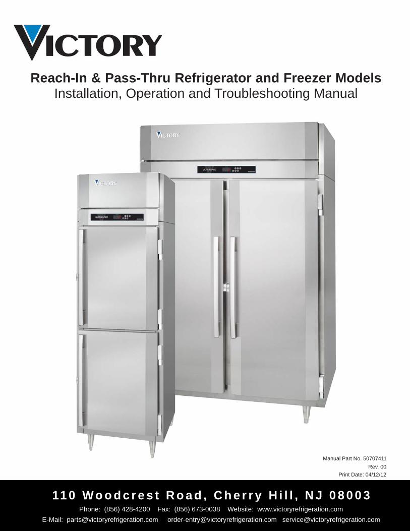
Reach-In & Pass-Thru Refrigerator and Freezer ModelsInstallation, Operation and Troubleshooting Manual
11 0 Wo o d c r e s t R o a d , C h e r r y H i l l , N J 0 8 0 0 3Phone: (856) 428-4200 Fax: (856) 673-0038 Website: www.victoryrefrigeration.com
E-Mail: [email protected] [email protected] [email protected]
Manual Part No. 50707411 Rev. 00
Print Date: 04/12/12
Thank you for purchasing a Victory ULTRASPEC™ Series cabinet! This unit has passed our strict Quality Control Inspection and meets the high standards set by Victory Refrigeration. You have made a quality investment that with proper maintenance will give you many years of service.
Please read the following installation and maintenance instructions before installing or using your unit. If you have any questions, please call our Technical Service Department at (800) 523- 5008.
IMPORTANT INFORMATION - PLEASE READ* Please read these instructions carefully before installing or using. If recommended procedures are not followed, warranty claims may be denied.
* Your Warranty Registration information is located on the next page of this manual. Please complete the card and submit it to Victory Refrigeration within 10 days of installation. Failure to properly register equipment may limit or void the warranty.
* Victory Refrigeration reserves the right to change specifications and product design without notice. Such revisions do not entitle the buyer to corresponding changes, improvements, additions or replacements for previously purchased equipment.
T H A N K Y O U
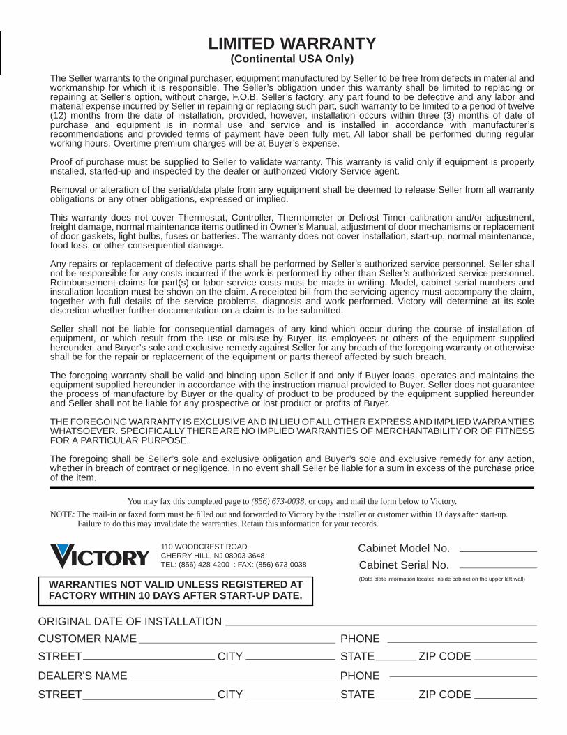
LIMITED WARRANTY(Continental USA Only)
The Seller warrants to the original purchaser, equipment manufactured by Seller to be free from defects in material and workmanship for which it is responsible. The Seller’s obligation under this warranty shall be limited to replacing or repairing at Seller’s option, without charge, F.O.B. Seller’s factory, any part found to be defective and any labor and material expense incurred by Seller in repairing or replacing such part, such warranty to be limited to a period of twelve (12) months from the date of installation, provided, however, installation occurs within three (3) months of date of purchase and equipment is in normal use and service and is installed in accordance with manufacturer’s recommendations and provided terms of payment have been fully met. All labor shall be performed during regular working hours. Overtime premium charges will be at Buyer’s expense.
Proof of purchase must be supplied to Seller to validate warranty. This warranty is valid only if equipment is properly installed, started-up and inspected by the dealer or authorized Victory Service agent.
Removal or alteration of the serial/data plate from any equipment shall be deemed to release Seller from all warranty obligations or any other obligations, expressed or implied.
This warranty does not cover Thermostat, Controller, Thermometer or Defrost Timer calibration and/or adjustment, freight damage, normal maintenance items outlined in Owner’s Manual, adjustment of door mechanisms or replacement of door gaskets, light bulbs, fuses or batteries. The warranty does not cover installation, start-up, normal maintenance, food loss, or other consequential damage.
Any repairs or replacement of defective parts shall be performed by Seller’s authorized service personnel. Seller shall not be responsible for any costs incurred if the work is performed by other than Seller’s authorized service personnel. Reimbursement claims for part(s) or labor service costs must be made in writing. Model, cabinet serial numbers and installation location must be shown on the claim. A receipted bill from the servicing agency must accompany the claim, together with full details of the service problems, diagnosis and work performed. Victory will determine at its sole discretion whether further documentation on a claim is to be submitted.
Seller shall not be liable for consequential damages of any kind which occur during the course of installation of equipment, or which result from the use or misuse by Buyer, its employees or others of the equipment supplied hereunder, and Buyer’s sole and exclusive remedy against Seller for any breach of the foregoing warranty or otherwise shall be for the repair or replacement of the equipment or parts thereof affected by such breach.
The foregoing warranty shall be valid and binding upon Seller if and only if Buyer loads, operates and maintains the equipment supplied hereunder in accordance with the instruction manual provided to Buyer. Seller does not guarantee the process of manufacture by Buyer or the quality of product to be produced by the equipment supplied hereunder and Seller shall not be liable for any prospective or lost product or profits of Buyer.
THE FOREGOING WARRANTY IS EXCLUSIVE AND IN LIEU OF ALL OTHER EXPRESS AND IMPLIED WARRANTIES WHATSOEVER. SPECIFICALLY THERE ARE NO IMPLIED WARRANTIES OF MERCHANTABILITY OR OF FITNESS FOR A PARTICULAR PURPOSE.
The foregoing shall be Seller’s sole and exclusive obligation and Buyer’s sole and exclusive remedy for any action, whether in breach of contract or negligence. In no event shall Seller be liable for a sum in excess of the purchase price of the item.
You may fax this completed page to (856) 673-0038, or copy and mail the form below to Victory. NOTE: The mail-in or faxed form must be fi lled out and forwarded to Victory by the installer or customer within 10 days after start-up. Failure to do this may invalidate the warranties. Retain this information for your records.
WARRANTIES NOT VALID UNLESS REGISTERED AT FACTORY WITHIN 10 DAYS AFTER START-UP DATE.
ORIGINAL DATE OF INSTALLATIONCUSTOMER NAMESTREET
DEALER'S NAME
STREET
PHONECITY STATE ZIP CODE
PHONE
CITY STATE ZIP CODE
110 WOODCREST ROADCHERRY HILL, NJ 08003-3648 TEL: (856) 428-4200 : FAX: (856) 673-0038
Cabinet Model No.Cabinet Serial No.(Data plate information located inside cabinet on the upper left wall)
Glossary of Common Terms & DescriptionsCCompressor - The compressor is the heart of the system. The compressor does just what it’s name states. It compresses the low pressure refrigerant vapor from the evaporator and compresses it into a high pressure vapor.The inlet to the compressor is called the “Suction Line”. It brings the low pressure vapor into the compressor.After the compressor compresses the refrigerant into a high pressure Vapor, it removes it to the outlet called the “Discharge Line”.
Condenser Coil - The “Discharge Line” leaves the compressor and runs to the inlet of the condenser coil located on top of the cabinet. Because the refrigerant is compressed, it is a hot high pressure vapor (as pressure goes up – temperature goes up). The hot vapor enters the condenser coil and starts to fl ow through the tubes. Cool air is blown across the outside of the fi nned tubes of the condenser coil (usually by a fan or water with a pump).Since air is cooler than the refrigerant, heat jumps from the tubing to the cooler air (energy goes from hot to cold – “latent heat”). As the heat is removed from the refrigerant, it reaches it’s “saturated temperature” and starts to “fl ash” (change states), into a high pressure liquid.The high pressure liquid leaves the condenser coil through the “liquid line” and travels to the “metering device”. Sometimes running through a fi lter dryer fi rst, to remove any dirt or foreign particles.
DDefrost - The term is used to identify the function of a refrigerator or freezer to remove frost or ice from the internal evaporator coil.
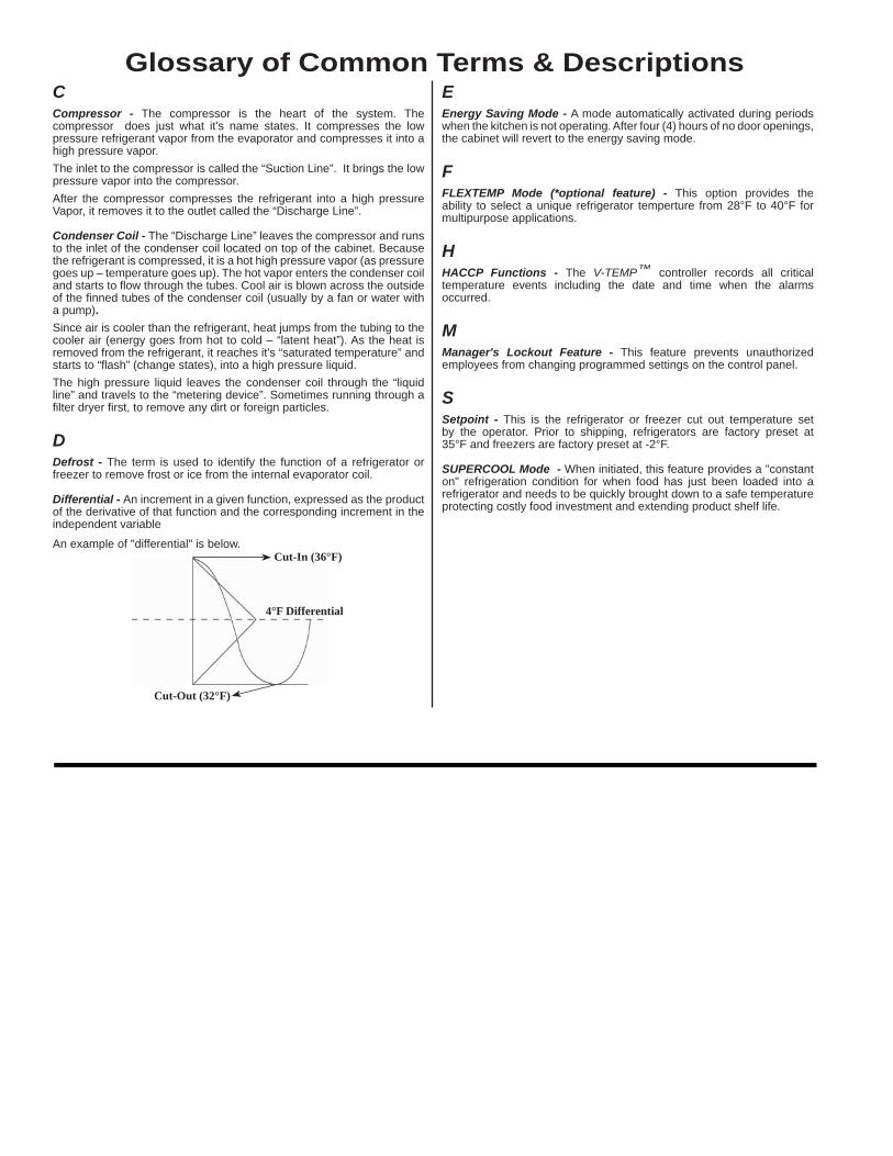
Differential - An increment in a given function, expressed as the product of the derivative of that function and the corresponding increment in the independent variable
An example of "differential" is below.
EEnergy Saving Mode - A mode automatically activated during periods when the kitchen is not operating. After four (4) hours of no door openings, the cabinet will revert to the energy saving mode.
FFLEXTEMP Mode (*optional feature) - This option provides the ability to select a unique refrigerator temperture from 28°F to 40°F for multipurpose applications.
HHACCP Functions - The V-TEMP™ controller records all critical temperature events including the date and time when the alarms occurred.
MManager's Lockout Feature - This feature prevents unauthorized employees from changing programmed settings on the control panel.
SSetpoint - This is the refrigerator or freezer cut out temperature set by the operator. Prior to shipping, refrigerators are factory preset at 35°F and freezers are factory preset at -2°F.
SUPERCOOL Mode - When initiated, this feature provides a "constant on" refrigeration condition for when food has just been loaded into a refrigerator and needs to be quickly brought down to a safe temperature protecting costly food investment and extending product shelf life.
Cut-In (36°F)
Cut-Out (32°F)
4°F Differential
Table of ContentsRECEIVING, UNCRATING & INSTALLATION Receiving...................................................................................................................................................................1
Uncrating.....................................................................................................................................................................................1
Storage Refrigerator/Freezer Location.......................................................................................................................1
Installing Legs or Casters...............................................................................................................................................1
Leveling............................................................................................................................................................................2
Cabinet Cleaning............................................................................................................................................................2
Installing Shelves..............................................................................................................................................................2
Electric Supply..................................................................................................................................................................2
Controller..........................................................................................................................................................................2 Installation Checklist..................................................................................................................................................2 Product Load..............................................................................................................................................................2
V-TEMP™ ELECTRONIC CONTROLLER LED Indicators & Alarms.............................................................................................................................................3
Keypad & Associated Functions .....................................................................................................................................3-5
Alarm Codes, Descriptions & Resolution(s)................................................................................................................5
Error Codes.......................................................................................................................................................................5
User Parameters............................................................................................................................................................6-7
PERIODIC CLEANING Cabinet Cleaning.......................................................................................................................................................8
Condenser Maintenance............................................................................................................................................8
Lubrication...............................................................................................................................................................9
Installing Replacement Door Gasket.........................................................................................................................9
TROUBLESHOOTING GUIDE FOR COMMON PROBLEMS Common Problems & Remedies.............................................................................................................................10
COMMON REPLACEMENT PARTS Refrigeration System Replacement Parts.................................................................................................................11
Controller Replacement Parts...................................................................................................................................11
Door Assembly Replacement Parts.....................................................................................................................11-12
Interior Light Assembly Replacement Parts.............................................................................................................12
WIRING DIAGRAMS 1, 2 & 3 Section Refrigerator 115 Volt/15 Amp & 20 Amp.........................................................................................13
1, 2 & 3 Section Refrigerator 115 Volt/208-230 Volt Condensing Unit......................................................................13
1, 2 & 3 Section Freezer 115 Volt/15 Amp & 20 Amp................................................................................................14
1, 2 & 3 Section Freezer 115 Volt/208-230 Volt Condensing Unit.............................................................................14
1
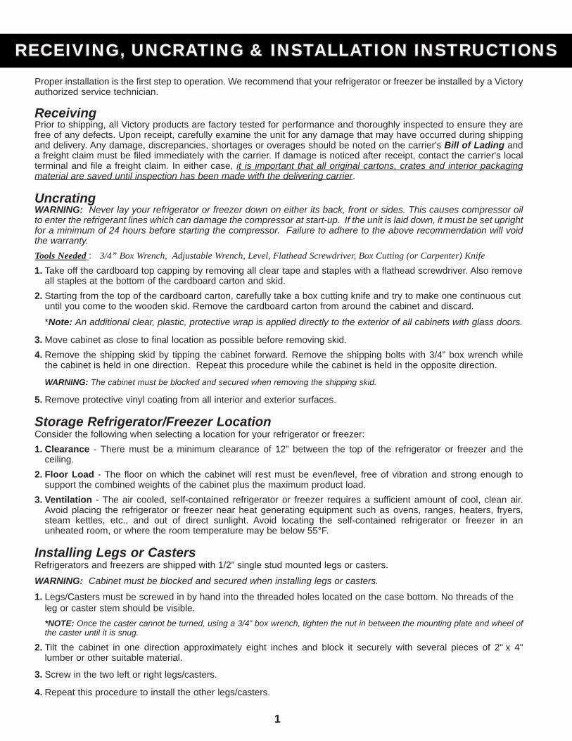
Proper installation is the first step to operation. We recommend that your refrigerator or freezer be installed by a Victory authorized service technician.
Receiving Prior to shipping, all Victory products are factory tested for performance and thoroughly inspected to ensure they are free of any defects. Upon receipt, carefully examine the unit for any damage that may have occurred during shipping and delivery. Any damage, discrepancies, shortages or overages should be noted on the carrier's Bill of Lading and a freight claim must be filed immediately with the carrier. If damage is noticed after receipt, contact the carrier's local terminal and file a freight claim. In either case, it is important that all original cartons, crates and interior packaging material are saved until inspection has been made with the delivering carrier.
UncratingWARNING: Never lay your refrigerator or freezer down on either its back, front or sides. This causes compressor oil to enter the refrigerant lines which can damage the compressor at start-up. If the unit is laid down, it must be set upright for a minimum of 24 hours before starting the compressor. Failure to adhere to the above recommendation will void the warranty. Tools Needed : 3/4” Box Wrench, Adjustable Wrench, Level, Flathead Screwdriver, Box Cutting (or Carpenter) Knife 1. Take off the cardboard top capping by removing all clear tape and staples with a flathead screwdriver. Also remove all staples at the bottom of the cardboard carton and skid. 2. Starting from the top of the cardboard carton, carefully take a box cutting knife and try to make one continuous cut until you come to the wooden skid. Remove the cardboard carton from around the cabinet and discard.
*Note: An additional clear, plastic, protective wrap is applied directly to the exterior of all cabinets with glass doors.
3. Move cabinet as close to final location as possible before removing skid. 4. Remove the shipping skid by tipping the cabinet forward. Remove the shipping bolts with 3/4” box wrench while the cabinet is held in one direction. Repeat this procedure while the cabinet is held in the opposite direction.
WARNING: The cabinet must be blocked and secured when removing the shipping skid. 5. Remove protective vinyl coating from all interior and exterior surfaces.
Storage Refrigerator/Freezer LocationConsider the following when selecting a location for your refrigerator or freezer:1. Clearance - There must be a minimum clearance of 12” between the top of the refrigerator or freezer and the ceiling.2. Floor Load - The floor on which the cabinet will rest must be even/level, free of vibration and strong enough to support the combined weights of the cabinet plus the maximum product load. 3. Ventilation - The air cooled, self-contained refrigerator or freezer requires a sufficient amount of cool, clean air. Avoid placing the refrigerator or freezer near heat generating equipment such as ovens, ranges, heaters, fryers, steam kettles, etc., and out of direct sunlight. Avoid locating the self-contained refrigerator or freezer in an unheated room, or where the room temperature may be below 55°F.
Installing Legs or CastersRefrigerators and freezers are shipped with 1/2” single stud mounted legs or casters.
WARNING: Cabinet must be blocked and secured when installing legs or casters.
1. Legs/Casters must be screwed in by hand into the threaded holes located on the case bottom. No threads of the leg or caster stem should be visible. *NOTE: Once the caster cannot be turned, using a 3/4” box wrench, tighten the nut in between the mounting plate and wheel of the caster until it is snug. 2. Tilt the cabinet in one direction approximately eight inches and block it securely with several pieces of 2" x 4" lumber or other suitable material.
3. Screw in the two left or right legs/casters.
4. Repeat this procedure to install the other legs/casters.
RECEIVING, UNCRATING & INSTALLATION INSTRUCTIONSRECEIVING, UNCRATING & INSTALLATION INSTRUCTIONS
2
LevelingCabinets must be leveled when installed. Failure to level your cabinet may result in doors not sealing, closing correctly,or condensate water not draining properly.
Legs - Rotate the foot of the leg with an adjustable wrench to achieve desired height for leveling. Casters - Cabinets with casters can be leveled by placing large flat washers in between the 1/2” stud and the holes located on the case bottom.
Cabinet CleaningPrior to use, the interior and exterior surfaces of the cabinet should be cleaned thoroughly with warm water, mild detergent and a soft cloth. Apply with a dampened cloth and wipe in the direction of the metal grain and allow to air dry with the door(s) open. DO NOT use chlorinated or abrasive cleansers, and only use a soft clean cloth.
Installing ShelvesAll cabinets with shelves are supplied with pilasters and shelf clip supports. Shelves are easily installed by inserting the shelf support clips into the pilasters so they fit tightly. Align the shelf so the smaller fill wires run from front to rear and rest the shelf on the clips.
Electric Supply 115 Volt self-contained units are provided with a 15 or 20 Amp power cord with plug that is shipped coiled on top of the cabinet. The power cord is equipped with a 3-prong (grounding) plug that is to be used in an appropriately rated and dedicated 3-prong (grounding) receptacle. *NOTE: Have a wall outlet checked by a qualified electrician for polarity and proper grounding prior to plugging in the power cord.
For units not provided with a power cord, the electrical connection should be made by a qualified electrician in accordance with local electrical codes. The electrical supply requirements are on the rating (or data) plate located on the left hand interior wall of the cabinet. Use of a dedicated circuit with separate grounding wire is required.
ControllerWhen first supplying power to the cabinet there will be approximately a one minute delay before the compressor and fan motors start to operate. Also, if power has been out for over 48 hours, a visible "rtc" (or Real Time Clock) error code will show in the display window. This indicates that the real time clock must be set. Please refer to page 4 "SETTING DATE AND TIME" section. The controller can be set to maintain temperature between 32°F (0.0°C) to 44°F (6.6°C) for refrigerators, and -6°F(-21.1°C) to 15°F (-9.4°C) for freezers. Prior to shipping, refrigerators are factory preset at 35°F and freezers are factorypreset at -2°F. *NOTE: Once the desired temperature "setpoint" has been chosen, there can be a +4 degree temperature difference shown within the controller display when the refrigerator cabinet is in operation, and +5 temperature difference for freezers. For example, a refrigerator controller "set point" is 32°F, but the refrigerator cabinet can operate between 32°F to 36°F.
Installation ChecklistAfter the cabinet has been installed, leveled and cleaned as described, refer to the following checklist prior to start-up.
Check for proper electrical hook-up. Cabinet must not share receptacle with another piece of equipment.
Check exposed refrigeration line connections for leaks. Make sure refrigeration lines are not dented, kinked or rubbing.
Check condenser & evaporator fan(s) for freedom to rotate without striking any stationary members.
Check that cabinet is level. Product LoadAfter the refrigerator or freezer has been started and reaches the proper storage temperatures, food may be loaded.For optimum energy efficiency and air flow we recommend minimum 1” clearance between the storage compartment cabinet walls and product load, 4" clearance between the storage compartment ceiling and product load, and a 1" clearance between the bottom of the storage compartment and product load.
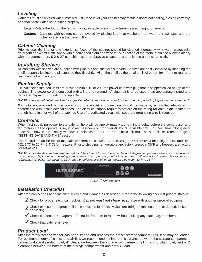
V-TEMP™ Control Panel
3
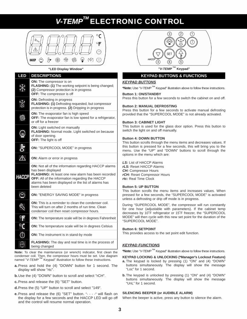
LED DESCRIPTIONSON: The compressor is onFLASHING: (1) The working setpoint is being changed; (2) Compressor protection is in progressOFF: The compressor is off
ON: Defrosting in progressFLASHING: (1) Defrosting requested, but compressor protection is in progress. (2) Dripping in progress
ON: The evaporator fan is high speedOFF: The evaporator fan is low speed for a refrigerator, or off for a freezer
ON: Light switched on manuallyFLASHING: Normal mode. Light switched on because of door opening.OFF: The light is off
ON: "SUPERCOOL MODE" in progress
ON: Alarm or error in progress
ON: Not all of the information regarding HACCP alarms has been displayedFLASHING: At least one new alarm has been recordedOFF: All of the information regarding the HACCP alarms has been displayed or the list of alarms has been deleted
ON: "ENERGY SAVING MODE" in progress
ON: This is a reminder to clean the condenser coil. This will turn on after 2 months of run time. Clean condenser coil then reset compressor hours.
ON: The temperature scale will be in degrees Fahrenheit
ON: The temperature scale will be in degrees Celsius
ON: The instrument is in stand-by mode
FLASHING: The day and real time is in the process of being changed
Note: To clear the maintenance (or wrench) indicator, first clean the condenser coil. Then, the compressor hours must be set. Use diagram named "V-TEMP™ Keypad" illustration to follow these instructions.
a. Press and hold the (4) "DOWN" button for 1 second. The display will show "rtc".
b. Use the (4) "DOWN" button to scroll and select "rCH".
c. Press and release the (6) "SET" button.
d. Press the (5) "UP" button to scroll and select "149".
e. Press and release the (6) "SET" button. “- - - -“ will flash on the display for a few seconds and the HACCP LED will go off and the control will resume normal operation.
KEYPAD BUTTONS*Note: Use "V-TEMP™ Keypad" illustration above to follow these instructions.
Button 1: ON/STANDBYPress this button for a few seconds to switch the cabinet on and off. Button 2: MANUAL DEFROSTINGPress this button for a few seconds to activate manual defrosting provided that the “SUPERCOOL MODE” is not already activated.
Button 3: CABINET LIGHTThis button is used for the glass door option. Press this button to switch the light on and off manually.
Button 4: DOWN BUTTONThis button scrolls through the menu items and decreases values. If this button is pressed for a few seconds, this will bring you to the menu. Use the “UP” and “DOWN” buttons to scroll through the options in the menu which are: LS: List of HACCP AlarmsrLS: Reset HACCP AlarmsCH: Compressor HoursrCH: Reset Compressor Hoursrtc: Real Time Clock
Button 5: UP BUTTONThis button scrolls the menu items and increases values. When pressed for a few seconds, the “SUPERCOOL MODE” is activated unless a defrosting or drip off mode is in progress.
During “SUPERCOOL MODE”, the compressor will run constantly for one hour (adjustable with parameters). If the cabinet temp decreases by 10˚F refrigerator or 15˚F freezer, the “SUPERCOOL MODE” will then cycle with this new set point for the duration of the “SUPERCOOL MODE”.
Button 6: SETPOINTThis provides access to the set point edit function.
KEYPAD FUNCTIONS*Note: Use "V-TEMP™ Keypad" illustration above to follow these instructions.
KEYPAD LOCKING & UNLOCKING (*Manager's Lockout Feature)a. The keypad is locked by pressing (1) “ON” and (4) “DOWN” buttons simultaneously. The display will show the message “Loc” for 1 second.
b. The keypad is unlocked by pressing (1) “ON” and (4) “DOWN” buttons simultaneously. The display will show the message “UnL” for 1 second.
SILENCING BEEPER (or AUDIBLE ALARM)When the beeper is active, press any button to silence the alarm.
V-TEMPV-TEMPTMTM ELECTRONIC CONTROLELECTRONIC CONTROL
"LED Display Window"
KEYPAD BUTTONS & FUNCTIONS
"V-TEMP™ Keypad"
4
KEYPAD FUNCTIONS (continued)*Note: Use "V-TEMP™ Keypad" illustration above to follow these instructions.
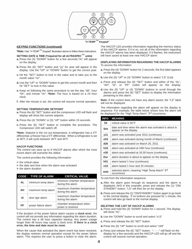
SETTING DATE & TIME (*required for all ULTRASPEC™ units)a. Press the (4) “DOWN” button for a few seconds,“rtc” will appear on the display.
b. Press the (6) “SET” button and “yy” for year will appear in the display. Use the “UP” or “DOWN” button to get the correct year.
c. Hit the “SET” button to lock in the value and to take you to the month value “nn”.
d. Use the “UP” or “DOWN” button to get the correct month and then hit “SET” to lock in this value.
e. Keep on following the same procedure to set the day “dd”, hour “hh”, and minute “nn”. *Note: The hour is based on a 24 hour clock.
f. After the minute is set, the control will resume normal operation.
SETTING TEMPERATURE SETPOINTa. Press the (6) “SET” button and the compressor LED will flash and display will show the current setpoint.
b. Press the (4) “DOWN” or (5) “UP” button within 15 seconds.
c. Press the (6) “SET” button to complete the procedure. The Compressor LED will switch off.
*Note: Setpoint is the cut out temperature. A refrigerator has a 4˚F differential; a freezer has a 5˚F differential. When a refrigerator is set at 36˚F, it will cycle between 36˚F and 40˚F.
HACCP FUNCTIONSThe control can save up to 9 HACCP alarms after which the mostrecent alarm will overwrite the oldest.
The control provides the following information:
> the critical value> the date and time when the alarm was activated> the alarm duration
CODE TYPE OF ALARM CRITICAL VALUE
AL minimum temp alarm minimum chamber temperature during this alarm
AH maximum temp alarm maximum chamber temperature during this alarm
id door ajar alarm maximum chamber temperature during this alarm
PF power failure alarm chamber temperature when power is restored
If the duration of the power failure alarm causes a clock error, the control will not provide any information regarding the alarm duration. The control has a 48 hour capacitor backup. Any power outage longer than 48 hours may cause a clock error. If there is a clockerror, the time and date must be reset.
When the cause that activated the alarm event has been resolved, the display restores normal operation except for the power failure alarm. This requires the user to press a button to clear the alarm.
The HACCP LED provides information regarding the memory status of the HACCP alarms. If it is on, not all of the information regarding the HACCP alarms has been displayed. If it flashes, the instrument will have saved at least one new HACCP alarm.
DISPLAYING INFORMATION REGARDING THE HACCP ALARMSTo access the information:
a. Press the (4) “DOWN” button for 2 seconds: the first label appears on the display.
b. Use the (5) “UP” or (4) “DOWN” button to select “LS” (List)
c. Press and release the (6) “SET” button and either of the “AL”, “AH”, “id”, or “PF” codes will appear on the display.
d. Use the (5) “UP” or (4) “DOWN” buttons to scroll through the alarms and press the (6) “SET” button to display the information pertaining to this alarm.
Note: If the control does not have any alarm saved, the “LS” label will not be displayed.
The information regarding the alarm will appear on the display in sequence. For example, the table below shows how the alarm will be displayed for the "High Temp Alarm" 3rd occurrence.
INFO MEANING55 critical value is 55°F
StA date and time when the alarm was activated is about to appear on the display
y11 alarm was activated year 2011 (continues)
n03 alarm was activated during month of March (continues)
d26 alarm was activated on March 26, 2011
h16 alarm was activated at 16th hour (continues)
n30 alarm was activated at 16:30 hours (continues)
Dur alarm duration is about to appear on the display
h01 alarm lasted 1 hour (continues)
n15 alarm lasted 1 hour and 15 minutes
AH3 selected alarm; meaning "High Temp Alarm" 3rd occurrence
To exit from the information sequence:
a. After the alarm goes through its sequence and the alarm is displayed, AH3 in this example, press and release the (1) “ON/ STANDBY” button: “LS” will then be on the display.
b. Press and release the (1) “ON/STANDBY” button again to go back to the normal display. If no buttons are pressed for 1 minute, the control will also go back to the normal display.
DELETING THE LIST OF HACCP ALARMSa. Press and hold the (4) “DOWN” button for 1 second. The display will show “rtc”. b. Use the “DOWN” button to scroll and select “rLS”
c. Press and release the (6) “SET” button
d. Press the (5) “UP” button to scroll and select “149”
e. Press and release the (6) “SET” button. “- - - -“ will flash on the display for a few seconds and the HACCP LED will go off and the control will resume normal operation.
"V-TEMP™ Keypad"
5
KEYPAD FUNCTIONS (continued)*Note: Use "V-TEMP™ Keypad" illustration above to follow these instructions.
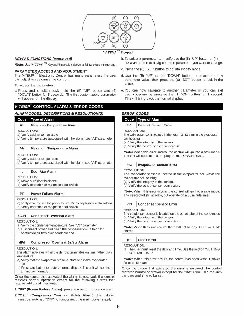
PARAMETER ACCESS AND ADJUSTMENTThe V-TEMP™ Electronic Control has many parameters the user can adjust to customize the control.
To access the parameters:a. Press and simultaneously hold the (5) “UP” button and (4) “DOWN” button for 5 seconds. The first customizable parameter will appear on the display.
b. To select a parameter to modify use the (5) “UP” button or (4) “DOWN” button to navigate to the parameter you want to change.
c. Press the (6) “SET” button to go into modify mode.
d. Use the (5) “UP” or (4) “DOWN” button to select the new parameter value, then press the (6) “SET” button to lock in the value.
e. You can now navigate to another parameter or you can exit this procedure by pressing the (1) “ON” button for 1 second. This will bring back the normal display.
"V-TEMP™ Keypad"
ALARM CODES, DESCRIPTIONS & RESOLUTION(S)Code Type of Alarm
AL Minimum Temperature AlarmRESOLUTION:(a) Verify cabinet temperature(b) Verify temperature associated with the alarm; see "A1" parameter
AH Maximum Temperature Alarm
RESOLUTION:(a) Verify cabinet temperature(b) Verify temperature associated with the alarm; see "A4" parameter
id Door Ajar AlarmRESOLUTION:(a) Make sure door is closed(b) Verify operation of magnetic door switch
PF Power Failure AlarmRESOLUTION:(a) Verify what caused the power failure. Press any button to stop alarm.(b) Verify operation of magnetic door switch
COH Condenser Overheat AlarmRESOLUTION:(a) Verify the condenser temperature. See "C6" parameter.(b) Disconnect power and clean the condenser coil. Check for obstructed air flow over condenser coil.
dFd Compressor Overheat Safety Alarm
RESOLUTION:This alarm activates when the defrost terminates on time rather than temperature.(a) Verify that the evaporator probe is intact and in the evaporator coil.(b) Press any button to restore normal display. The unit will continue to function normally.
Once the cause that activated the alarm is resolved, the control restores normal operation except for the following alarms thatrequire additional intervention:
1. "PF" (Power Failure Alarm): press any button to silence alarm
2. "CSd" (Compressor Overheat Safety Alarm): the cabinet must be switched "OFF", or disconnect the main power supply
ERROR CODESCode Type of AlarmPr1 Cabinet Sensor Error
RESOLUTION:The cabinet sensor is located in the return air stream in the evaporator coil housing.(a) Verify the integrity of the sensor. (b) Verify the control sensor connection.
*Note: When this error occurs, the control will go into a safe mode. The unit will operate in a pre-programmed ON/OFF cycle.
Pr2 Evaporator Sensor ErrorRESOLUTION:The evaporator sensor is located in the evaporator coil within theevaporator coil housing.(a) Verify the integrity of the sensor. (b) Verify the control-sensor connection.
*Note: When this error occurs, the control will go into a safe mode. The defrost will still activate, but operate on a 30 minute timer.
Pr3 Condenser Sensor ErrorRESOLUTION:The condenser sensor is located on the outlet tube of the condenser.(a) Verify the integrity of the sensor.(b) Verify the control-sensor connection.
*Note: When this error occurs, there will not be any "COH" or "Csd" alarms.
rtc Clock ErrorRESOLUTION:(a) The user must reset the date and time. See the section "SETTING DATE AND TIME".
*Note: When this error occurs, the control has been without power for over 48 hours.
Once the cause that activated the error is resolved, the control restores normal operation except for the "rtc" error. This requires the date and time to be set.
V-TEMPV-TEMPTMTM CONTROL ALARM & ERROR CODES
6
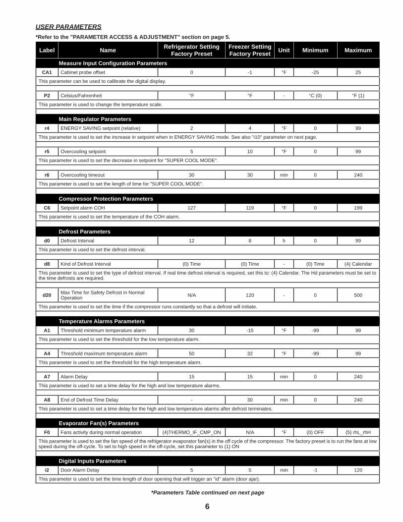
USER PARAMETERS*Refer to the "PARAMETER ACCESS & ADJUSTMENT" section on page 5.
Label Name Refrigerator Setting Factory Preset
Freezer Setting Factory Preset Unit Minimum Maximum
Measure Input Configuration ParametersCA1 Cabinet probe offset 0 -1 °F -25 25
This parameter can be used to calibrate the digital display.
P2 Celsius/Fahrenheit °F °F - °C (0) °F (1)
This parameter is used to change the temperature scale.
Main Regulator Parametersr4 ENERGY SAVING setpoint (relative) 2 4 °F 0 99
This parameter is used to set the increase in setpoint when in ENERGY SAVING mode. See also "i10" parameter on next page.
r5 Overcooling setpoint 5 10 °F 0 99
This parameter is used to set the decrease in setpoint for "SUPER COOL MODE".
r6 Overcooling timeout 30 30 min 0 240
This parameter is used to set the length of time for "SUPER COOL MODE".
Compressor Protection ParametersC6 Setpoint alarm COH 127 119 °F 0 199
This parameter is used to set the temperature of the COH alarm.
Defrost Parametersd0 Defrost Interval 12 8 h 0 99
This parameter is used to set the defrost interval.
d8 Kind of Defrost Interval (0) Time (0) Time - (0) Time (4) Calendar
This parameter is used to set the type of defrost interval. If real time defrost interval is required, set this to: (4) Calendar. The Hd parameters must be set to the time defrosts are required.
d20 Max Time for Safety Defrost in Normal Operation N/A 120 - 0 500
This parameter is used to set the time if the compressor runs constantly so that a defrost will initiate.
Temperature Alarms ParametersA1 Threshold minimum temperature alarm 30 -15 °F -99 99
This parameter is used to set the threshold for the low temperature alarm.
A4 Threshold maximum temperature alarm 50 32 °F -99 99
This parameter is used to set the threshold for the high temperature alarm.
A7 Alarm Delay 15 15 min 0 240
This parameter is used to set a time delay for the high and low temperature alarms.
A8 End of Defrost Time Delay - 30 min 0 240
This parameter is used to set a time delay for the high and low temperature alarms after defrost terminates.
Evaporator Fan(s) ParametersF0 Fans activity during normal operation (4)THERMO_IF_CMP_ON N/A °F (0) OFF (5) rhL_rhH
This parameter is used to set the fan speed of the refrigerator evaporator fan(s) in the off cycle of the compressor. The factory preset is to run the fans at low speed during the off-cycle. To set to high speed in the off-cycle, set this parameter to (1) ON
Digital Inputs Parametersi2 Door Alarm Delay 5 5 min -1 120
This parameter is used to set the time length of door opening that will trigger an "id" alarm (door ajar).
*Parameters Table continued on next page
7
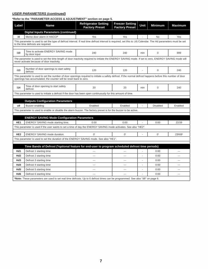
Label Name Refrigerator Setting Factory Preset
Freezer Setting Factory Preset Unit Minimum Maximum
Digital Inputs Parameters (continued)i4 Memo door alarm in HACCP Yes Yes - No Yes
This parameter is used to set the type of defrost interval. If real time defrost interval is required, set this to: (4) Calendar. The Hd parameters must be set to the time defrosts are required.
i10 Time to activate ENERGY SAVING mode by door input 240 240 min 0 999
The parameter is used to set the time length of door inactivity required to initiate the ENERGY SAVING mode. If set to zero, ENERGY SAVING mode will never activate because of door inactivity.
i13 Number of door openings to start safety defrost 120 120 - 0 240
This parameter is used to set the number of door openings required to initiate a safety defrost. If the normal defrost happens before this number of door openings has accumulated, the counter will be reset back to zero.
i14 Time of door opening to start safety defrost. 20 20 min 0 240
This parameter is used to initiate a defrost if the door has been open continuously for this amount of time.
Outputs Configuration Parametersu9 Buzzer enabling Enabled Enabled - Disabled Enabled
This parameter is used to enable or disable the alarm buzzer. The factory preset is for the buzzer to be active.
ENERGY SAVING Mode Configuration ParametersHE1 ENERGY SAVING mode starting time. 0:00 0:00 - 0:00 23:59
This parameter is used if the user wants to set a time of day the ENERGY SAVING mode activates. See also "HE2".
HE2 ENERGY SAVING mode duration. 0' 0' - 0' 23h59'
This parameter is used to set the duration of the ENERGY SAVING mode. See also "HE1".
Time Bands of Defrost (*optional feature for end-user to program scheduled defrost time periods)Hd1 Defrost 1 starting time --- --- - 0:00 ---
Hd2 Defrost 2 starting time --- --- - 0:00 ---
Hd3 Defrost 3 starting time --- --- - 0:00 ---
Hd4 Defrost 4 starting time --- --- - 0:00 ---
Hd5 Defrost 5 starting time --- --- - 0:00 ---
Hd6 Defrost 6 starting time --- --- - 0:00 ---
*Note: These parameters are used to set real time defrosts. Up to 6 defrost times can be programmed. See also "d8" on page 6.
USER PARAMETERS (continued)*Refer to the "PARAMETER ACCESS & ADJUSTMENT" section on page 5.
Cabinet CleaningVictory Refrigeration recommends periodic internal and exterior cleaning as outlined below.
Daily Exterior Cleaning 1. Clean the surface with a sponge and cleaning solution. Use a non-abrasive cleaner that does not contain chlorine. 2. Polish with a soft cloth, wiping with the grain of the metal. 3. Once a week wipe with a film cutting agent or stainless steel polish to maintain shine.
Weekly Interior Cleaning 1. Remove all food, food related items and shelves. 2. Discontinue power to the cabinet at the main power supply circuit breaker. 3. Remove loose food particles from the interior floors, walls and ceiling. 4. Scrub all interior surfaces and door gaskets with a warm detergent solution 100°F (38°C) - 120°F (49°C) and a soft nylon bristled brush. 5. Rinse with clear water and allow to air dry. 6. Reinstall the shelves. 7. Return power to the cabinet by resetting main power supply circuit breaker. 8. Return food to the cabinet when temperature indicator reaches safe food temperature.
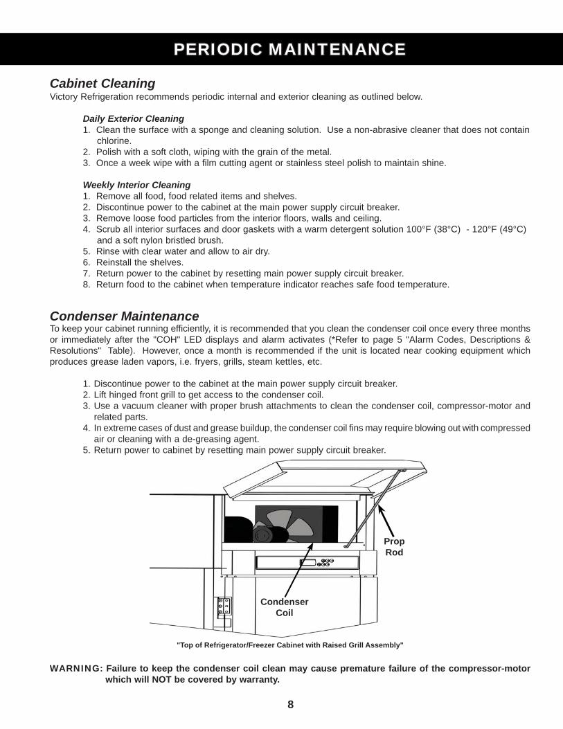
Condenser MaintenanceTo keep your cabinet running efficiently, it is recommended that you clean the condenser coil once every three months or immediately after the "COH" LED displays and alarm activates (*Refer to page 5 "Alarm Codes, Descriptions & Resolutions" Table). However, once a month is recommended if the unit is located near cooking equipment which produces grease laden vapors, i.e. fryers, grills, steam kettles, etc.
1. Discontinue power to the cabinet at the main power supply circuit breaker. 2. Lift hinged front grill to get access to the condenser coil. 3. Use a vacuum cleaner with proper brush attachments to clean the condenser coil, compressor-motor and related parts. 4. In extreme cases of dust and grease buildup, the condenser coil fins may require blowing out with compressed air or cleaning with a de-greasing agent. 5. Return power to cabinet by resetting main power supply circuit breaker.
"Top of Refrigerator/Freezer Cabinet with Raised Grill Assembly"
WARNING: Failure to keep the condenser coil clean may cause premature failure of the compressor-motor which will NOT be covered by warranty.
8
PERIODIC MAINTENANCEPERIODIC MAINTENANCE
PropRod
Condenser Coil
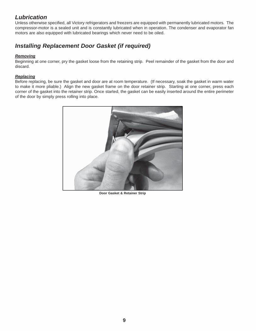
LubricationUnless otherwise specified, all Victory refrigerators and freezers are equipped with permanently lubricated motors. The compressor-motor is a sealed unit and is constantly lubricated when in operation. The condenser and evaporator fan motors are also equipped with lubricated bearings which never need to be oiled. Installing Replacement Door Gasket (if required)RemovingBeginning at one corner, pry the gasket loose from the retaining strip. Peel remainder of the gasket from the door and discard.
ReplacingBefore replacing, be sure the gasket and door are at room temperature. (If necessary, soak the gasket in warm water to make it more pliable.) Align the new gasket frame on the door retainer strip. Starting at one corner, press each corner of the gasket into the retainer strip. Once started, the gasket can be easily inserted around the entire perimeter of the door by simply press rolling into place.
9
Door Gasket & Retainer Strip
10
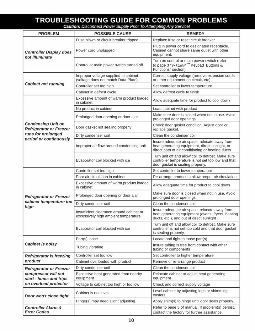
PROBLEM POSSIBLE CAUSE REMEDY
Controller Display does not illuminate
Fuse blown or circuit breaker tripped Replace fuse or reset circuit breaker
Power cord unpluggedPlug in power cord to designated receptacle. Cabinet cannot share same outlet with other equipment.
Control or main power switch turned offTurn on control or main power switch (refer to page 3 "V-TEMP™ Keypad Buttons & Functions" section)
Cabinet not running
Improper voltage supplied to cabinet (voltage does not match Data-Plate)
Correct supply voltage (remove extension cords or other equipment on circuit, etc).
Controller set too high Set controller to lower temperatureCabinet in defrost cycle Allow defrost cycle to fi nish
Condensing Unit on Refrigerator or Freezer runs for prolonged period or continuously
Excessive amount of warm product loaded in cabinet Allow adequate time for product to cool down
No product in cabinet Load cabinet with product
Prolonged door opening or door ajar Make sure door is closed when not in use. Avoid prolonged door openings.
Door gasket not sealing properly Check door gasket condition. Adjust door or replace gasket.
Dirty condenser coil Clean the condenser coil
Improper air fl ow around condensing unitInsure adequate air space, relocate away from heat generating equipment, direct sunlight, or direct path of air conditioning or heating ducts
Evaporator coil blocked with iceTurn unit off and allow coil to defrost. Make sure controller temperature is not set too low and that door gasket is sealing properly.
Refrigerator or Freezer cabinet temperature too high
Controller set too high Set controller to lower temperaturePoor air circulation in cabinet Re-arrange product to allow proper air circulationExcessive amount of warm product loaded in cabinet Allow adequate time for product to cool down
Prolonged door opening or door ajar Make sure door is closed when not in use. Avoid prolonged door openings.
Dirty condenser coil Clean the condenser coil
Insuffi cient clearance around cabinet or excessively high ambient temperature
Insure adequate air space, relocate away from heat generating equipment (ovens, fryers, heating ducts, etc.), and out of direct sunlight
Evaporator coil blocked with iceTurn unit off and allow coil to defrost. Make sure controller is not set too cold and that door gasket is sealing properly.
Cabinet is noisyPart(s) loose Locate and tighten loose part(s)
Tubing vibrating Insure tubing is free from contact with other tubing or components
Refrigerator is freezing product
Controller set too low Set controller to higher temperatureCabinet overloaded with product Remove or re-arrange product
Refrigerator or Freezer compressor will not start - hums and trips on overload protector
Dirty condenser coil Clean the condenser coilExcessive heat generated from nearby equipment
Relocate cabinet or adjust heat generating equipment
Voltage to cabinet too high or too low Check and correct supply voltage
Door won't close tightCabinet is not level Level cabinet by adjusting legs or shimming
castersHinge(s) may need slight adjusting. Apply shim(s) to hinge until door seals properly.
Controller Alarm & Error Codes ---- Refer to page 5 of manual. If problem(s) persist,
contact the factory for further assistance.
TROUBLESHOOTING GUIDE FOR COMMON PROBLEMSTROUBLESHOOTING GUIDE FOR COMMON PROBLEMSCaution:Caution: Disconnect Power Supply Prior To Attempting Any Service! Disconnect Power Supply Prior To Attempting Any Service!
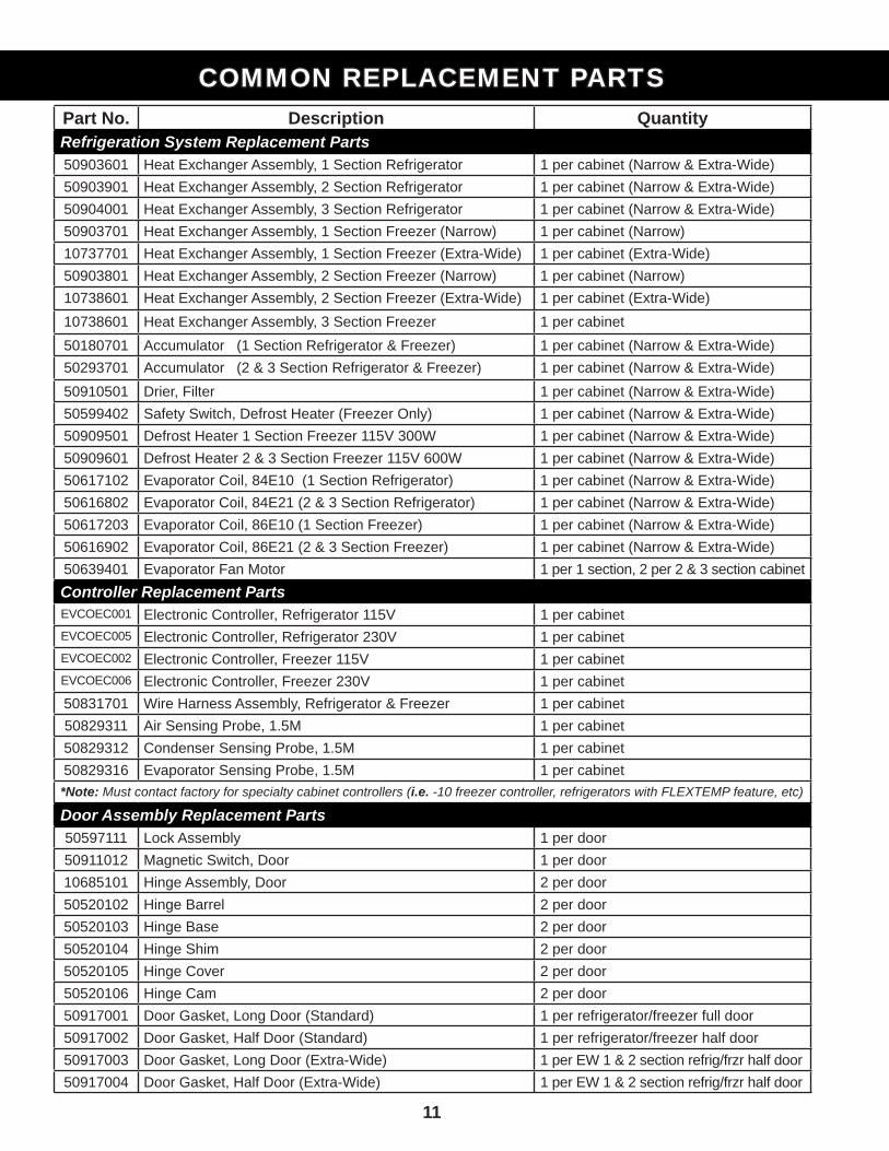
Part No. Description QuantityRefrigeration System Replacement Parts50903601 Heat Exchanger Assembly, 1 Section Refrigerator 1 per cabinet (Narrow & Extra-Wide)50903901 Heat Exchanger Assembly, 2 Section Refrigerator 1 per cabinet (Narrow & Extra-Wide)50904001 Heat Exchanger Assembly, 3 Section Refrigerator 1 per cabinet (Narrow & Extra-Wide)50903701 Heat Exchanger Assembly, 1 Section Freezer (Narrow) 1 per cabinet (Narrow)10737701 Heat Exchanger Assembly, 1 Section Freezer (Extra-Wide) 1 per cabinet (Extra-Wide)50903801 Heat Exchanger Assembly, 2 Section Freezer (Narrow) 1 per cabinet (Narrow)10738601 Heat Exchanger Assembly, 2 Section Freezer (Extra-Wide) 1 per cabinet (Extra-Wide)10738601 Heat Exchanger Assembly, 3 Section Freezer 1 per cabinet50180701 Accumulator (1 Section Refrigerator & Freezer) 1 per cabinet (Narrow & Extra-Wide)50293701 Accumulator (2 & 3 Section Refrigerator & Freezer) 1 per cabinet (Narrow & Extra-Wide)50910501 Drier, Filter 1 per cabinet (Narrow & Extra-Wide)50599402 Safety Switch, Defrost Heater (Freezer Only) 1 per cabinet (Narrow & Extra-Wide)50909501 Defrost Heater 1 Section Freezer 115V 300W 1 per cabinet (Narrow & Extra-Wide)50909601 Defrost Heater 2 & 3 Section Freezer 115V 600W 1 per cabinet (Narrow & Extra-Wide)50617102 Evaporator Coil, 84E10 (1 Section Refrigerator) 1 per cabinet (Narrow & Extra-Wide)50616802 Evaporator Coil, 84E21 (2 & 3 Section Refrigerator) 1 per cabinet (Narrow & Extra-Wide)50617203 Evaporator Coil, 86E10 (1 Section Freezer) 1 per cabinet (Narrow & Extra-Wide)50616902 Evaporator Coil, 86E21 (2 & 3 Section Freezer) 1 per cabinet (Narrow & Extra-Wide)50639401 Evaporator Fan Motor 1 per 1 section, 2 per 2 & 3 section cabinetController Replacement PartsEVCOEC001 Electronic Controller, Refrigerator 115V 1 per cabinetEVCOEC005 Electronic Controller, Refrigerator 230V 1 per cabinetEVCOEC002 Electronic Controller, Freezer 115V 1 per cabinetEVCOEC006 Electronic Controller, Freezer 230V 1 per cabinet50831701 Wire Harness Assembly, Refrigerator & Freezer 1 per cabinet50829311 Air Sensing Probe, 1.5M 1 per cabinet50829312 Condenser Sensing Probe, 1.5M 1 per cabinet50829316 Evaporator Sensing Probe, 1.5M 1 per cabinet*Note: Must contact factory for specialty cabinet controllers (i.e. -10 freezer controller, refrigerators with FLEXTEMP feature, etc)
Door Assembly Replacement Parts50597111 Lock Assembly 1 per door50911012 Magnetic Switch, Door 1 per door10685101 Hinge Assembly, Door 2 per door50520102 Hinge Barrel 2 per door50520103 Hinge Base 2 per door50520104 Hinge Shim 2 per door50520105 Hinge Cover 2 per door50520106 Hinge Cam 2 per door50917001 Door Gasket, Long Door (Standard) 1 per refrigerator/freezer full door50917002 Door Gasket, Half Door (Standard) 1 per refrigerator/freezer half door50917003 Door Gasket, Long Door (Extra-Wide) 1 per EW 1 & 2 section refrig/frzr half door50917004 Door Gasket, Half Door (Extra-Wide) 1 per EW 1 & 2 section refrig/frzr half door
COMMON REPLACEMENT PARTSCOMMON REPLACEMENT PARTS
11
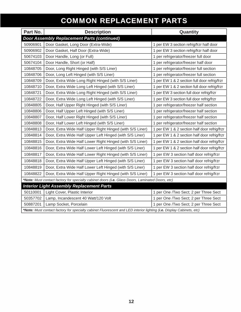
Part No. Description QuantityDoor Assembly Replacement Parts (continued)50906901 Door Gasket, Long Door (Extra-Wide) 1 per EW 3 section refrig/frzr half door50906902 Door Gasket, Half Door (Extra-Wide) 1 per EW 3 section refrig/frzr half door50674103 Door Handle, Long (or Full) 1 per refrigerator/freezer full door50674104 Door Handle, Short (or Half) 1 per refrigerator/freezer half door10848705 Door, Long Right Hinged (with S/S Liner) 1 per refrigerator/freezer full section10848706 Door, Long Left Hinged (with S/S Liner) 1 per refrigerator/freezer full section10848709 Door, Extra Wide Long Right Hinged (with S/S Liner) 1 per EW 1 & 2 section full door refrig/frzr 10848710 Door, Extra Wide Long Left Hinged (with S/S Liner) 1 per EW 1 & 2 section full door refrig/frzr 10848721 Door, Extra Wide Long Right Hinged (with S/S Liner) 1 per EW 3 section full door refrig/frzr 10848722 Door, Extra Wide Long Left Hinged (with S/S Liner) 1 per EW 3 section full door refrig/frzr 10848805 Door, Half Upper Right Hinged (with S/S Liner) 1 per refrigerator/freezer half section10848806 Door, Half Upper Left Hinged (with S/S Liner) 1 per refrigerator/freezer half section10848807 Door, Half Lower Right Hinged (with S/S Liner) 1 per refrigerator/freezer half section10848808 Door, Half Lower Left Hinged (with S/S Liner) 1 per refrigerator/freezer half section10848813 Door, Extra Wide Half Upper Right Hinged (with S/S Liner) 1 per EW 1 & 2 section half door refrig/frzr 10848814 Door, Extra Wide Half Upper Left Hinged (with S/S Liner) 1 per EW 1 & 2 section half door refrig/frzr 10848815 Door, Extra Wide Half Lower Right Hinged (with S/S Liner) 1 per EW 1 & 2 section half door refrig/frzr 10848816 Door, Extra Wide Half Lower Left Hinged (with S/S Liner) 1 per EW 1 & 2 section half door refrig/frzr 10848817 Door, Extra Wide Half Lower Right Hinged (with S/S Liner) 1 per EW 3 section half door refrig/frzr 10848818 Door, Extra Wide Half Upper Left Hinged (with S/S Liner) 1 per EW 3 section half door refrig/frzr 10848819 Door, Extra Wide Half Lower Left Hinged (with S/S Liner) 1 per EW 3 section half door refrig/frzr 10848822 Door, Extra Wide Half Upper Right Hinged (with S/S Liner) 1 per EW 3 section half door refrig/frzr *Note: Must contact factory for specialty cabinet doors (i.e. Glass Doors, Laminated Doors, etc)
Interior Light Assembly Replacement Parts50110001 Light Cover, Plastic Interior 1 per One /Two Sect; 2 per Three Sect50357702 Lamp, Incandescent 40 Watt/120 Volt 1 per One /Two Sect; 2 per Three Sect50887201 Lamp Socket, Porcelain 1 per One /Two Sect; 2 per Three Sect*Note: Must contact factory for specialty cabinet Fluorescent and LED interior lighting (i.e. Display Cabinets, etc)
COMMON REPLACEMENT PARTSCOMMON REPLACEMENT PARTS
12
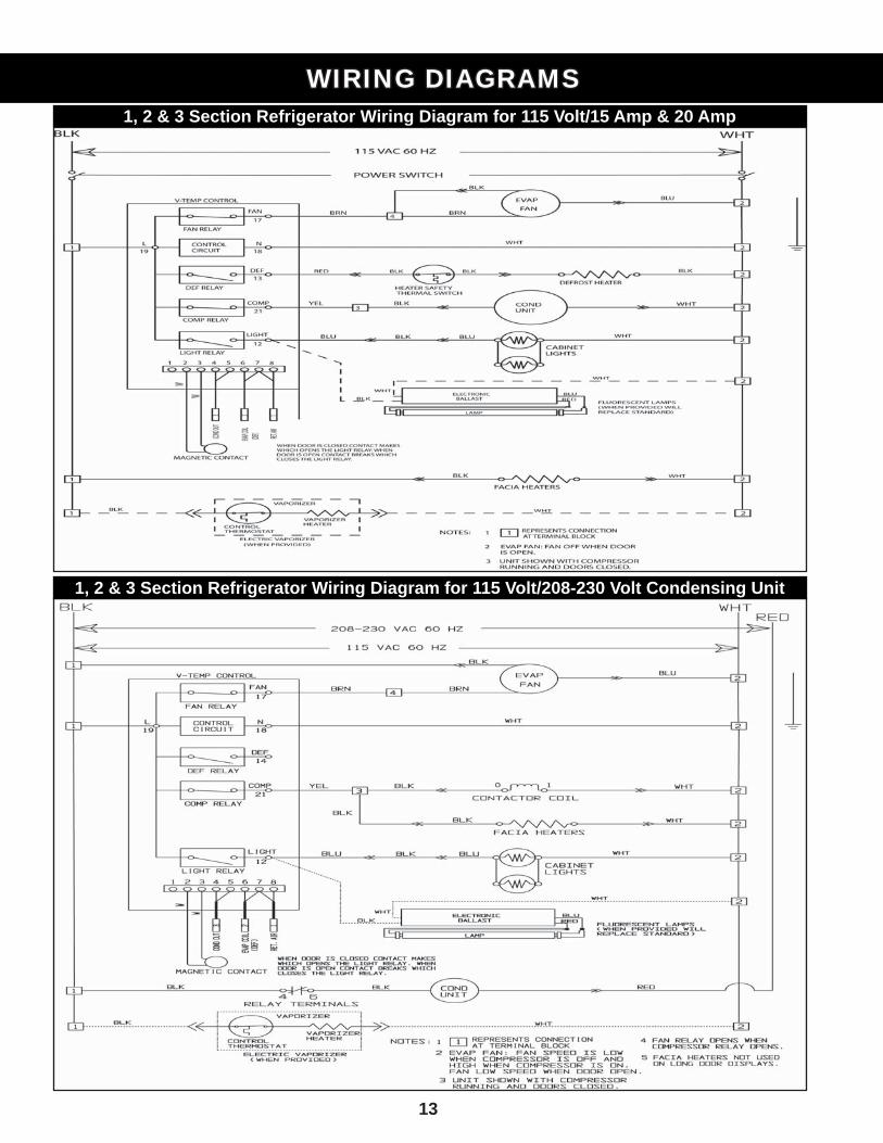
13
WIRING DIAGRAMSWIRING DIAGRAMS1, 2 & 3 Section Refrigerator Wiring Diagram for 115 Volt/15 Amp & 20 Amp
1, 2 & 3 Section Refrigerator Wiring Diagram for 115 Volt/208-230 Volt Condensing Unit
14
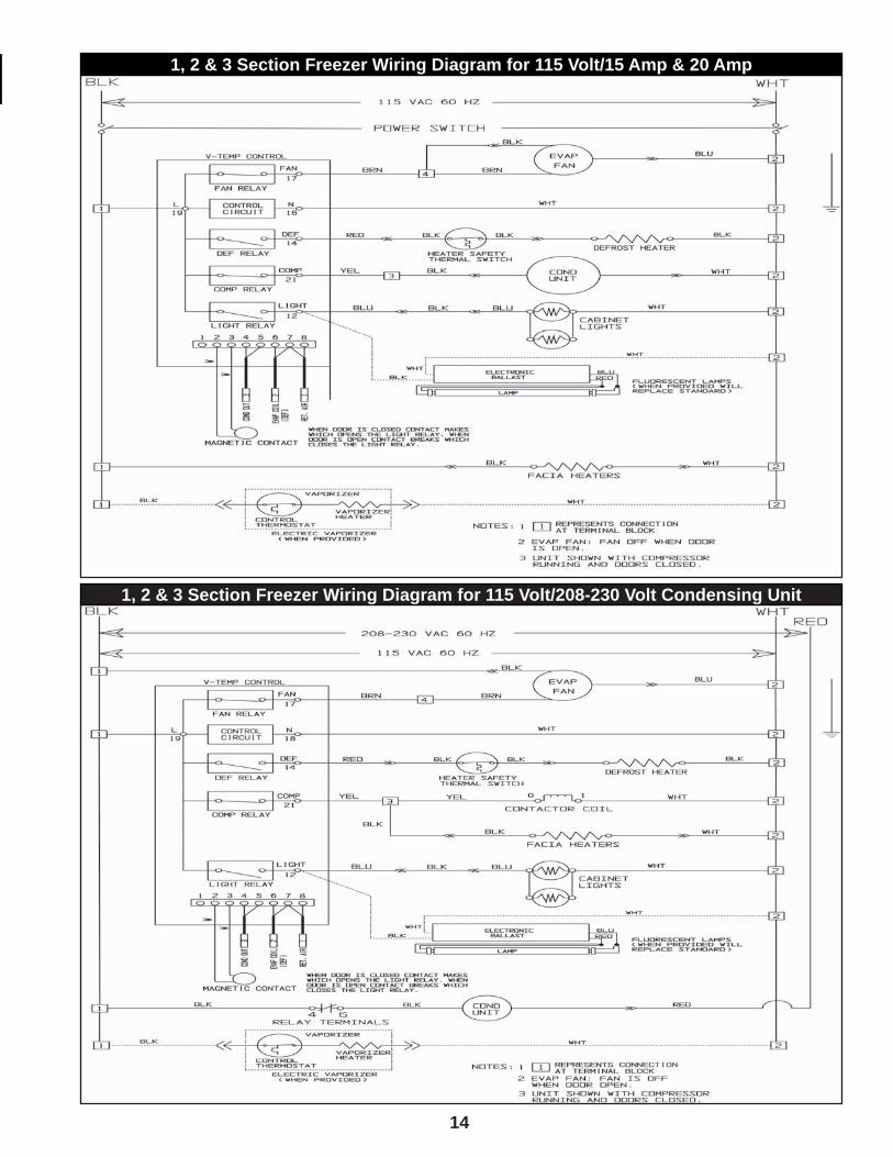
1, 2 & 3 Section Freezer Wiring Diagram for 115 Volt/15 Amp & 20 Amp
1, 2 & 3 Section Freezer Wiring Diagram for 115 Volt/208-230 Volt Condensing Unit

11 0 Wo o d c r e s t R o a d , C h e r r y H i l l , N J 0 8 0 0 3Phone: (856) 428-4200 Fax: (856) 673-0038 Website: www.victoryrefrigeration.com
E-Mail: [email protected] [email protected] [email protected]