Embed Size (px)
DESCRIPTION
Type MCR 15
Citation preview

IndustrialHydraulics
Electric Drivesand Controls
Linear Motion andAssembly Technologies Pneumatics
ServiceAutomation
MobileHydraulics
Size 1130 to 2150Series 3XMaximum operating pressure 450 barMaximum displacement volume 2150 cm3
Maximum output torque 13688 Nm
Features
– compact, sturdy construction
– smooth running even at very low speeds
– low noise
– reversible
– sealed tapered roller bearing
– high radial forces permitted on output shaft
– shaft seal up to 10 bar
– optional integral holding brake (multi-disc brake) or wheelbrake (drum brake)
– switchable
• freewheeling
• half displacement
– for open and closed circuits
Type MCR 15
RE 15 208/10.94 1/8Replaces: 15 217
Contents
Description Page
Features 1
Section, Function 1, 2
Ordering codes, symbols 3
Technical data 4, 5
Unit dimensions, radial loads "C" 6
Unit dimensions, radial loads "F" 7
Unit dimensions (holding brake and wheel brake) 8
Hydraulic Motor(Radial Piston, Multi-Stroke)
H/A 2388
Function (open and closed circuits)
Closed circuitClosed circuitClosed circuitClosed circuitClosed circuit
Minimum inlet pressure must be adapted to suit operatingconditions; the following must be taken into consideration:idling pressure, flow resistances, pump operation.Minimum flow of the feed pump must be adapted to suitoperating conditions.
Open circuitOpen circuitOpen circuitOpen circuitOpen circuit
Minimum inlet pressure must be adapted to suit operatingconditions; the following must be taken into consideration:idling pressure, flow resistances, pump operation.The outlet pressure must be at least 2 bar greater than thepressure in the housing.
If the motor circuits are in series please consult theIf the motor circuits are in series please consult theIf the motor circuits are in series please consult theIf the motor circuits are in series please consult theIf the motor circuits are in series please consult themanufacturer.manufacturer.manufacturer.manufacturer.manufacturer.
2/8 Bosch Rexroth AG | Mobile Hydraulics MCR 15 | RE 15 208/10.94
B A
Hydraulic motors Type MCR are radial piston motors with arotating shaft.
ConstructionConstructionConstructionConstructionConstructionTwo-part housing (1; 2), rotary piston assembly (3; 4) cam (5),output shaft (6) and control section (7)
TransmissionTransmissionTransmissionTransmissionTransmissionThe rotor (4) is connected to the shaft (6) by means of splines.Thepistons (3) are arranged radially in the rotor (4) and are supportedon the cam plate (5) by way of rollers (8).
Torque generationTorque generationTorque generationTorque generationTorque generation
The number of working and idle strokes corresponds to thenumber of cams on the stroke curve.
Open loop controlOpen loop controlOpen loop controlOpen loop controlOpen loop controlThe cylinder chambers (E) are connected to ports A or B bymeans of the axial bores and the annular passages (D).
BearingsBearingsBearingsBearingsBearingsTapered roller bearings capable of transmitting high axial andradial forces.
FreewheelingFreewheelingFreewheelingFreewheelingFreewheelingIf the two ports A and B are connected with no pressure loadingand a pressure of 2 bar is simultaneously applied to the housingby way of port “L” , the pistons will be forced into the rotary pistonassembly. The rollers will no longer be lying against the cam curveand it will be possible for the end of the shaft to be rotated.
Switching to half displacementSwitching to half displacementSwitching to half displacementSwitching to half displacementSwitching to half displacementOn certain models of radial piston motors halving of displacementis possible. This means that at working stroke only half the pistonsare supplied with fluid by way of a valve in the control system. Theremaining pistons are connected to the outlet side of the motor.When connected the motor will run at twice the speed but at halftorque.
Section, Function
11111
66666
Wheel brakeWheel brakeWheel brakeWheel brakeWheel brake (drum brake)
MountingMountingMountingMountingMountingDirectly onto output shaft(6) and flange housing (1).
Operating the brakeOperating the brakeOperating the brakeOperating the brakeOperating the brake
• hydraulichydraulichydraulichydraulichydraulic –for dynamic braking
• mechanicalmechanicalmechanicalmechanicalmechanical –as a holding brake
Mounting:Mounting:Mounting:Mounting:Mounting:By way of control housing(2) and through drive.
Brake applicationBrake applicationBrake applicationBrake applicationBrake applicationIf the pressure in theannular area (9) falls shortof a pre-determined level,the Belleville washer (10)will press the disc package(11) together.
Brake releaseBrake releaseBrake releaseBrake releaseBrake releaseIf the pressure in theannular area (9) exceedsthe required level, the brakepiston (12) will be pushedagainst the Belleville washer(10). The load is taken offthe disc package (11), andthe holding brake released.
99999
1313131313
1010101010
1212121212
22222
1111111111
66666AAAAA BBBBB
Mounting the brakesMounting the brakesMounting the brakesMounting the brakesMounting the brakesHolding brakeHolding brakeHolding brakeHolding brakeHolding brake (multi-disc brake)
66666
11111 88888
DDDDD77777DDDDDDDDDD 22222 77777
55555 33333
Feed
Working stroke Idle stroke
Return
RE 15 208/10.94 | MCR 15 Mobile Hydraulics | Bosch Rexroth AG 3/8
A
B L
L X A B
A
B
Z A
B L
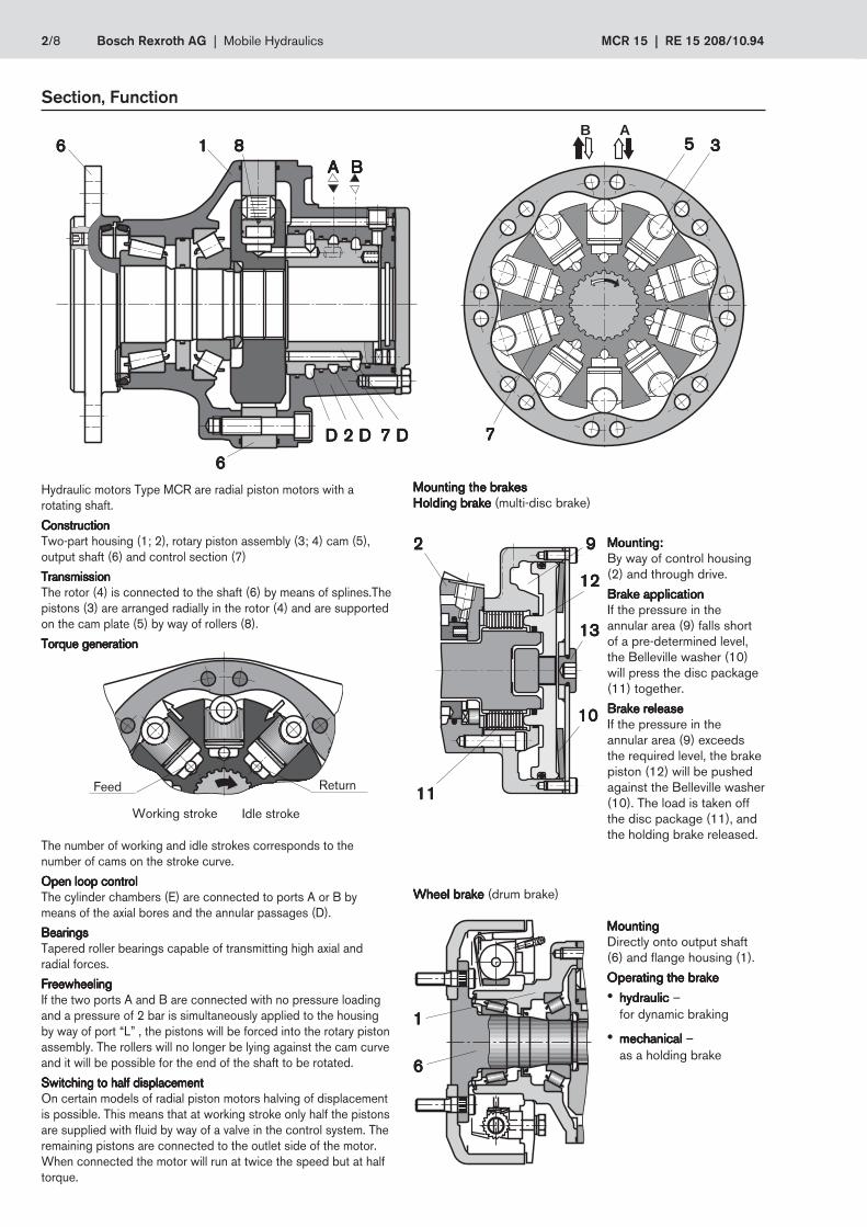
Ordering codes
Flange housingFlange housingFlange housingFlange housingFlange housingCompact version = C= C= C= C= CWheel version = F= F= F= F= F
SizesSizesSizesSizesSizes/Displacement VSize 1130 = 1130 cm3 = 1130= 1130= 1130= 1130= 1130Size 1250 = 1250 cm3 = 1250= 1250= 1250= 1250= 1250Size 1500 = 1500 cm3 = 1500= 1500= 1500= 1500= 1500Size 1780 = 1780 cm3 = 1780= 1780= 1780= 1780= 1780Size 2150 = 2150 cm3 = 2150= 2150= 2150= 2150= 2150
1st shaft end1st shaft end1st shaft end1st shaft end1st shaft endwith flange 250 1) = F 250= F 250= F 250= F 250= F 250with flange 280 2) = F 280= F 280= F 280= F 280= F 280
withoutwithoutwithoutwithoutwithout 2nd shaft end = Z = Z = Z = Z = Z
SeriesSeriesSeriesSeriesSeries = 3X= 3X= 3X= 3X= 3XSeries 30 to 39(30 to 39, externally interchangeable)
1) only with flange housing C2) only with flange housing F
MCRMCRMCRMCRMCR 1515151515 ZZZZZ –––––3X3X3X3X3X MMMMM *****
Symbols to DIN ISO 1219
LLLLL
Motor for two speedsMotor for two speedsMotor for two speedsMotor for two speedsMotor for two speeds
Motor withMotor withMotor withMotor withMotor withholding brakeholding brakeholding brakeholding brakeholding brake
Motor withMotor withMotor withMotor withMotor withwheel brakewheel brakewheel brakewheel brakewheel brake
Further detailsin clear text
StudsStudsStudsStudsStudsno code =no code =no code =no code =no code = without studs/S =/S =/S =/S =/S = with studs for
wheel mounting
PortsPortsPortsPortsPorts11 =11 =11 =11 =11 = BSP thread to ISO 228/142 =42 =42 =42 =42 = UNF-SAE threads
no code =no code =no code =no code =no code = not switchable,anti-clockwise rotation preferred
2R =2R =2R =2R =2R = switchable, clockw. rotation preferred2L =2L =2L =2L =2L = switchable, anti-clw. rotation preferred
Seals Seals Seals Seals SealsM =M =M =M =M = NBR seals, suitable for
mineral oil to DIN 51 524 (HL, HLP)
Brake mounting Brake mounting Brake mounting Brake mounting Brake mountingAOAOAOAOAO ===== without brakeB11B11B11B11B11 ===== hydraulic holding brake
(spring pressure disc brake)2) C12RC12RC12RC12RC12R ===== Wheel brake (drum brake)
for right side of vehicle, see Fig. on page 82) C12LC12LC12LC12LC12L ===== Wheel brake (drum brake)
for left side of vehicle, see Fig. on page 8

4/8 Bosch Rexroth AG | Mobile Hydraulics MCR 15 | RE 15 208/10.94
Technical data (For applications outside these parameters please consult us)
General General General General GeneralType Piston machineModel Radial piston multi-stroke motor, switchable displacementType code MCR 15...Type of mounting Flange mounting; face mountingType of connection Threaded, flangeMounting position OptionalShaft load See pages 6, 7Direction of rotation Right / left - reversibleFrame size 15Nominal size 1130 1250 1500 1780 2150Displacement V cm3 1130 1250 1500 1780 2150Displacement flow at n = 100 rev/min/100 bar Q L/min 114 126 151 179 216Output torque 1), 7)
– spec. torque T Nm 1799 1990 2388 2833 3422 (at ∆p = 100 bar)– max. torque T Nm 8095 8955 9552 11332 13688
Output torque 1; 7)– min. speed n rev/min 5 to 10 when running smooth, depending on application– max. speed n rev/min 150 150 150 125 125– freewheeling n rev/min 300
Output power 1)– continuous power P kW 55 55 55 60 60
Weight – motor m kg 93– motor with holding brake m kg 120– motor with wheel brake m kg 135
HydraulicHydraulicHydraulicHydraulicHydraulicNominal pressure p bar 250Pressure difference, cont. 2), 6), 7) ∆p
– with mineral oil (HL, HLP) bar 250Pressure difference, peak 3), 6), 7) ∆p
– with mineral oil (HL, HLP) bar 450 400Inlet pressure port “A” or “B” p bar 470 420Summated pressure 4; 6) port “A” + “B” p bar 470 420Case drain pressure p bar 10Fluid 5) Mineral oil (HL, HLP) to DIN 51 524Fluid temperature range ϑ °C – 20 to +80Viscosity range ν mm2/s 10 to 2000Fluid cleanliness Max. permissible degree of contamination of the fluid to
NAS 1638 class 9. We therefore recommend a filter witha minimum retention rate of ß10 ≥ 75.
Brake Brake Brake Brake BrakeHolding brake (multi-disc brake)Holding torque T Nm 11 000Brake release pressure, min – max p bar Min. 15 max. 30Wheel brake (drum brake) See table page 8
1) The data given apply after 100 hours running-in time2) Continuous operation3) Peak values may occur for a maximum duration of one second within an operating minute.4) In the return line we recommend pmin = 15 bar5) Environmentally friendly fluids HETG, HEPG, HEE to RE 90 2216) For connection in series, please consult the technical sales department.7) Warning!Warning!Warning!Warning!Warning! During the running-in time of the motor (min. 20 hours) motors should not be run unloaded at greater than
50% of maximum speed.

RE 15 208/10.94 | MCR 15 Mobile Hydraulics | Bosch Rexroth AG 5/8
Notes on the technical dataNotes on the technical dataNotes on the technical dataNotes on the technical dataNotes on the technical data
T = torque in Nm Q = input flow in L/min QL = case leakage in L/min
– All torques given apply to run-in motors (see page 4, footnote 7 )– For "half displacement" operating mode multiply the torques and Q–values by 0.5.– The torques given for 50% displacement do not apply to both directions of rotation, but only to the preferred direction of rotation
indicated (see page 4)
Technical data (Mean values, measured at ν = 46 mm2/s and ϑ = 45 °C)
Nominal Size 1130 1780Speed n in rev/min 0 25 50 100 150 0 25 50 100 150
T Nm 1133 1529 1583 1493 1397 1558 2456 2420 2043100 Q L/min 0,72 28,95 57,40 114,19 171,31 0,74 45,41 90,05 179,22
QL L/min 0,20 0,20 0,30 0,50 0,90 0,37 0,41 0,45 0,53T Nm 2447 3166 3238 3166 3133 3683 5049 5116 4833
200 Q L/min 2,18 29,59 58,09 114,98 172,16 2,18 46,55 91,22 180,55QL L/min 0,40 0,40 0,50 0,60 1,00 1,09 1,11 1,13 1,17T Nm 3670 4749 4858 4694 5949 7692 7794
300 Q L/min 4,04 30,10 59,02 115,52 4,04 48,00 93,10QL L/min 0,50 0,50 0,70 0,70 2,02 2,15 2,28T Nm 4892 6331 6474 8160 10335 10425
400 Q L/min 5,84 31,00 59,81 5,82 49,46 94,81QL L/min 1,00 1,00 1,00 2,92 3,21 3,50T Nm 5503 7122 7284
450 Q L/min 6,90 31,46 60,59QL L/min 1,10 1,10 1,30
Nominal Size 1250 2150Speed n in rev/min 0 25 50 100 150 0 25 50 100
T Nm 1253 1692 1751 1691 1512 1882 2967 2922 2467100 Q L/min 0,74 31,95 63,40 126,19 189,31 0,72 54,66 108,55 216,22
QL L/min 0,20 0,20 0,30 0,50 0,90 0,37 0,41 0,45 0,53T Nm 2707 3503 3582 3503 4448 6098 6180
200 Q L/min 2,18 32,59 64,09 126,98 2,18 55,80 109,72QL L/min 0,40 0,40 0,50 0,60 1,09 1,11 1,13T Nm 4060 5254 5373 7186 9290 9414
300 Q L/min 4,04 33,10 65,02 4,04 57,25 111,60QL L/min 0,50 0,50 0,70 2,02 2,15 2,28T Nm 5411 7003 7162 9855 12483
400 Q L/min 5,82 34,00 65,81 5,84 58,71QL L/min 1,00 1,00 1,00 2,92 3,21T Nm 6088 7878 8057
450 Q L/min 6,90 34,46 66,59QL L/min 1,10 1,10 1,30
Nominal Size 1500Speed n in rev/min 0 25 50 100 150
T Nm 1504 2030 2101 1983 1719100 Q L/min 0,40 37,90 75,60 151,00 226,80
QL L/min 0,20 0,20 0,30 0,50 0,90T Nm 3248 4203 4298 4203
200 Q L/min 0,80 38,30 76,00 151,20QL L/min 0,40 0,40 0,50 0,60T Nm 4872 6304 6448
300 Q L/min 1,00 38,50 76,40QL L/min 0,50 0,50 0,70T Nm 6494 8403 8594
400 Q L/min 2,00 39,50 77,40QL L/min 1,00 1,00 1,00T Nm 7305 9454 9669
450 Q L/min 2,20 39,70 77,60QL L/min 1,10 1,10 1,30
6/8 Bosch Rexroth AG | Mobile Hydraulics MCR 15 | RE 15 208/10.94
0 -400-80 -160 -240 -32080160240320400
FR
mmmm
70
NG 2150NG 1500
100
10
20
30
40
50
60
90
80
B A B A B A
Ø 3
75
Ø 3
35
115
Ø 2
50
Ø 2
05
Ø 1
60,8
-0,2
5
40
21
R3
Ø 3
04±0
,25
5555
105
Ø 2
85-0
,21
5628,5�
105
288,4179,5 98,9
73,45736,5
168
41,5
20° 10° 10° 20° 9
6 x Ø 20+0,1
X
A
B
L
F
X
A
B
L
R20
8 x Ø22,4+0,35–0,1
8 x M10 x 17
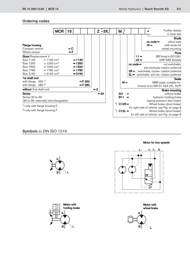
Unit dimensions (in mm)
Permissible radial load on output shaftMeasured at speed n = 50 rev/min, pressure difference ∆p = 250 bar
Direction of rotation (viewed on shaft end)
Ordering code “2L”“2L”“2L”“2L”“2L” Ordering code “2R”“2R”“2R”“2R”“2R”
Standard design Switchable (preferred direction)
Port Dimensions of threadsOrdering code "11""11""11""11""11" Ordering code "42""42""42""42""42"
A, B 3/4 SAE (410 bar/6000 PSI)
L,F 1/2" BSP 3/4-16 SAE
X 3/8" BSP 9/16-18 SAE
11111 Port A; B (inlet, outlet)
22222 Case drain port L
33333 Filling port F, may also be used as drain port
44444 Pilot port X for switching displacement,ordering code ..2L....2L....2L....2L....2L.. or ..2R....2R....2R....2R....2R..(switching pressure p = 10 to 30 bar)
55555 Shaft end with flange, ordering code "F250""F250""F250""F250""F250"
Distance L in mm
F R in
kN
Shaft end ...F 250...Shaft end ...F 250...Shaft end ...F 250...Shaft end ...F 250...Shaft end ...F 250...Flange housing ...C...Flange housing ...C...Flange housing ...C...Flange housing ...C...Flange housing ...C...
+++++–––––
FA max (FR = 0) = +63 686NFA max (FR = 0) = –20 800N
Flange housing:Flange housing:Flange housing:Flange housing:Flange housing:Ordering code "C""C""C""C""C"
1111122222
44444
33333
6666655555
66666 M18 x 1,5 studs with nut, for retaining wheelsordering code ../S..../S..../S..../S..../S..
Size 1500Size 1500Size 1500Size 1500Size 1500Size 2150Size 2150Size 2150Size 2150Size 2150

RE 15 208/10.94 | MCR 15 Mobile Hydraulics | Bosch Rexroth AG 7/8
0 -400
180
20
-80 -160 -240 -32080160240320400
FRmmmm
40
60
80
160
140
120
100
NG 2100NG 1500
0 -400-80 -160 -240 -32080160240320400
FR
mmmm
70
NG 2150NG 1500
100
10
20
30
40
50
60
90
80
Ø 3
75
Ø 3
35
115
Ø 2
80Ø
225
Ø 1
75,8
-0,2
50
23
R3
Ø 3
04±0
,25
5555
105
Ø 2
85-0
,21
5628,5�
105
334,4219,5 98,9
73,45736,5
1614
41,5
20° 10° 10° 20° 9
10 x Ø 24+0,1
X
A
B
L
F
X
A
B
L
R20
15,5
Ø 1
908 x Ø22,4+0,35
–0,1
8 x M10 x 17
B A B A B A
Flange housing:Flange housing:Flange housing:Flange housing:Flange housing:Ordering code "F""F""F""F""F"
Permissible radial load on output shaft
Port Dimensions of threadsOrdering code "11""11""11""11""11" Ordering code "42""42""42""42""42"
A, B 3/4 SAE (410 bar/6000 PSI)
L, F 1/2" BSP 3/4-16 SAE
X 3/8" BSP 9/16-18 SAE
Pipe thread (…"BSP) to ISO 228/1
11111 Port A; B (inlet, outlet)
22222 Case drain port L
33333 Filling port F, may also be used as drain port
44444 Pilot port X for switching displacement,ordering code ..2L....2L....2L....2L....2L.. or ..2R....2R....2R....2R....2R..(switching pressure p = 10 to 30 bar)
55555 Shaft end with flange, ordering code "F280""F280""F280""F280""F280"
Measured at speed n = 50 rev/min, pressure difference ∆p = 250 bar
F R in
kN
Shaft end ...F 280...Shaft end ...F 280...Shaft end ...F 280...Shaft end ...F 280...Shaft end ...F 280...Flange housing ...F...Flange housing ...F...Flange housing ...F...Flange housing ...F...Flange housing ...F...
F R in
kN
+++++–––––
FA max (FR = 0) = + 63 686NFA max (FR = 0) = – 34 000N
+++++–––––
FA max (FR = 0) = + 63 686NFA max (FR = 0) = – 77 500N
Shaft end ...F 280...Shaft end ...F 280...Shaft end ...F 280...Shaft end ...F 280...Shaft end ...F 280...Flange housing ...F...Flange housing ...F...Flange housing ...F...Flange housing ...F...Flange housing ...F...Wheel brake ...C.12...Wheel brake ...C.12...Wheel brake ...C.12...Wheel brake ...C.12...Wheel brake ...C.12...
Unit dimensions (in mm)
33333
444446666655555
22222
11111
66666 M22 x 1,5 studs with nut, for retaining wheelsordering code ../S..../S..../S..../S..../S..
Standard design Switchable (preferred direction)
Ordering code “2R”“2R”“2R”“2R”“2R”Ordering code “2L”“2L”“2L”“2L”“2L”
Direction of rotation (viewed on shaft end)
Distance L in mm Distance L in mm
Size 1500Size 1500Size 1500Size 1500Size 1500Size 2150Size 2150Size 2150Size 2150Size 2150
Size 1500Size 1500Size 1500Size 1500Size 1500Size 2100Size 2100Size 2100Size 2100Size 2100
Bosch Rexroth AGMobile HydraulicsZum Eisengießer 197816 Lohr am Main, GermanyTelefon +49 (0) 93 52-18 0Telefax +49 (0) 93 52-18 23 [email protected]/brm
Bosch Rexroth LimitedMobile Hydraulics-ManufacturingViewfieldGB-Glenrothes, Fife KY6 2RDTelefon +44 (1592) 63 17 77Telefax +44 (1592) 63 18 88
8/8 Bosch Rexroth AG | Mobile Hydraulics MCR 15 | RE 15 208/10.94
© 2003 by Bosch Rexroth AG, Mobile Hydraulics, D-97813 Lohr am MainAll rights reserved. No part of this document may be reproduced or stored,processed, duplicated or circulated using electronic systems, in any form or byany means, without the prior written authorisation of Bosch Rexroth AG.In the event of contravention of the above provisions, the contravening party isobliged to pay compensation.The data specified above only serves to describe the product. No statementsconcerning a certain condition or suitability for a certain application can bederived from our information.The details stated do not release you from theresponsibility for carrying out your own assessment and verification. It must beremembered that our products are subject to a natural process of wear andageing.
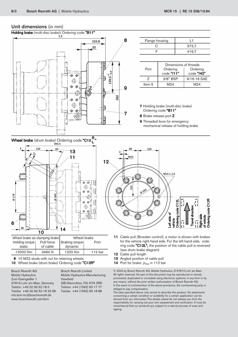
Unit dimensions (in mm)
Dimensions of threadsPort Ordering Ordering
code "/11""/11""/11""/11""/11" code "/42""/42""/42""/42""/42"
Z 3/8" BSP 9/16-18 SAE
Item 9 M24 M24
77777 Holding brake (multi-disc brake)Ordering code “B11”“B11”“B11”“B11”“B11”
88888 Brake release port Z Z Z Z Z
99999 Threaded bore for emergencymechanical release of holding brake
Holding brake Holding brake Holding brake Holding brake Holding brake (multi-disc brake)::::: Ordering code "B11" "B11" "B11" "B11" "B11"
Flange housing L1
C 373,7
F 419,7
RRRRRWheel brakeWheel brakeWheel brakeWheel brakeWheel brake (drum brake) Ordering code "C12 ""C12 ""C12 ""C12 ""C12 "LLLLL
6 6 6 6 6 10 M22 studs with nut for retaining wheels1010101010 Wheel brake (drum brake) Ordering code "C12R""C12R""C12R""C12R""C12R"
Wheel brake as clamping brake Wheel brakeHolding torque Pull force Braking torque Port
static of cable dynamic
12000 Nm 3460 N 1200 Nm 112 bar
Ø 1
76
40
132
M10
113
17
393,4
2 30°
Ø 3
65
36
801°
120
Ø 225
M14 x 1,5
1212121212
1010101010
666661414141414
13131313131111111111
1111111111 Cable pull (Bowden control), a motor is shown with brakesfor the vehicle right hand side. For the left hand side, orde-ring code "C12L","C12L","C12L","C12L","C12L", the position of the cable pull is reversed(see drum brake diagram)
1212121212 Cable pull length1313131313 Angled position of cable pull1414141414 Port for brake: pmax = 112 bar
L1
Z
110,8
33
282
139,
50 –0
,5
77777
88888
99999
Fah
rtri
chtu
ng
Left
side
of
Left
side
of
Left
side
of
Left
side
of
Left
side
of
vehi
cle
vehi
cle
vehi
cle
vehi
cle
vehi
cle
Ord
erin
g co
de C
12L
Ord
erin
g co
de C
12L
Ord
erin
g co
de C
12L
Ord
erin
g co
de C
12L
Ord
erin
g co
de C
12L
Rig
ht s
ide
Rig
ht s
ide
Rig
ht s
ide
Rig
ht s
ide
Rig
ht s
ide
of v
ehic
leof
veh
icle
of v
ehic
leof
veh
icle
of v
ehic
leO
rder
ing
code
C12
RO
rder
ing
code
C12
RO
rder
ing
code
C12
RO
rder
ing
code
C12
RO
rder
ing
code
C12
R
Trav
el d
irect
ion
Trav
el d
irect
ion
Trav
el d
irect
ion
Trav
el d
irect
ion
Trav
el d
irect
ion


![Ill 94 < 94 s 94 s s 94 s H S H H c-u oo 0-1 E] S 70 s 94 ... · 0-1 E] S 70 s 94 a S 94 H S S Ill S 0k S s s 94 S Ilk o 8 94 94 H 94 00 r 94 94 S 9-4... H S H O S 94 cvcv S Ok 94](https://img.pdfslide.us/doc/110x75/60020834a0102029af0fa7e7/ill-94-94-s-94-s-s-94-s-h-s-h-h-c-u-oo-0-1-e-s-70-s-94-0-1-e-s-70-s-94.jpg)


![オムロン ヘルスケア9-1 94 9-1 s s s s 94 4} q s 94 94 S 94 s s s s s cu s o 94 s o s 94 s o q s éFR àíí 1.1] s O s Èit s O O 94 94 O 94 c; Fit c- Fit -i o s @ H ÑlÙGÄ-r](https://img.pdfslide.us/doc/110x75/610c466a1e8234327c1f0c6b/fff-ff-9-1-94-9-1-s-s-s-s-94-4-q-s-94-94-s-94-s-s-s-s-s-cu.jpg)