Embed Size (px)
Citation preview
SAHC2014 – 9th International Conference on
Structural Analysis of Historical Constructions
F. Peña & M. Chávez (eds.)
Mexico City, Mexico, 14–17 October 2014
RE-STRENGTHENING 20th
CENTURY ARCHITECTURAL HERITAGE:
A CASE STUDY OF BRISBANE CITY HALL RESTORATION
Arturo Cruz
Queensland University of Technology (QUT)
2 George St, Brisbane QLD, Australia
Keywords: Structural Restoration, Reinforced Concrete, Modern Heritage, 20th
Century
Heritage, Heritage Conservation
Abstract: Restoring old buildings to conform the current building policies and standards is
a great challenge to engineers and architects. The restoration of the Brisbane City Hall, a
heritage building listed by the State of Queensland in Australia, developed an innovative
approach to upgrade the building using the method called ‘concrete overlay’ following the
guidelines of both the International Council on Monuments and Sites and the Burra Charter of
Australia. Concrete overlay is a new method of structural strengthening by drilling new
reinforcement and placing new concrete on top of the existing structure, akin to a bone
transplant or bone grafting in the case of a human being. This method is popularly used for
newer bridges which have suffered load stresses. However, this method had never been used on
any heritage buildings which were built on different conditions and standards. The compatibility
of this method is currently being monitored.
Most of the modern historic buildings are rapidly deteriorating and require immediate
interventions in order to be saved. As most of these heritage buildings are on the stage of
advanced deterioration, significant attempts are being made and several innovations are being
applied to upgrade these structures to conform with the current building requirements. To date,
the knowledge and literature in regarding ‘concrete cancer’ in relation to rehabilitating these
reinforced concrete heritage structures is significantly lacking. It is hoped that the method of
concrete overlay and the case study of Brisbane City Hall restoration will contribute to the
development of restoration techniques and policies for Modern Heritage Buildings.

Arturo Cruz
1
1. INTRODUCTION
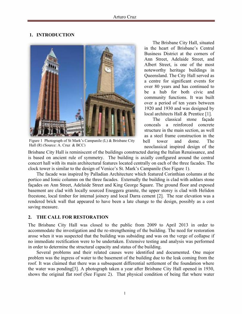
The Brisbane City Hall, situated
in the heart of Brisbane’s Central
Business District at the corners of
Ann Street, Adelaide Street, and
Albert Street, is one of the most
noteworthy heritage buildings in
Queensland. The City Hall served as
a centre for significant events for
over 80 years and has continued to
be a hub for both civic and
community functions. It was built
over a period of ten years between
1920 and 1930 and was designed by
local architects Hall & Prentice [1].
The classical stone façade
conceals a reinforced concrete
structure in the main section, as well
as a steel frame construction in the
bell tower and dome. The
neoclassical inspired design of the
Brisbane City Hall is reminiscent of the buildings constructed during the Italian Renaissance, and
is based on ancient rule of symmetry. The building is axially configured around the central
concert hall with its main architectural features located centrally on each of the three facades. The
clock tower is similar to the design of Venice’s St. Mark’s Campanile (See Figure 1).
The facade was inspired by Palladian Architecture which featured Corinthian columns at the
portico and Ionic columns on the three facades. Externally the building is clad with ashlars stone
façades on Ann Street, Adelaide Street and King George Square. The ground floor and exposed
basement are clad with locally sourced Enoggera granite, the upper storey is clad with Helidon
freestone, local timber for internal joinery and local Darra cement [2]. The rear elevation was a
rendered brick wall that appeared to have been a late change to the design, possibly as a cost
saving measure.
2. THE CALL FOR RESTORATION
The Brisbane City Hall was closed to the public from 2009 to April 2013 in order to
accommodate the investigation and the re-strengthening of the building. The need for restoration
arose when it was suspected that the building was subsiding and was on the verge of collapse if
no immediate rectification were to be undertaken. Extensive testing and analysis was performed
in order to determine the structural capacity and status of the building.
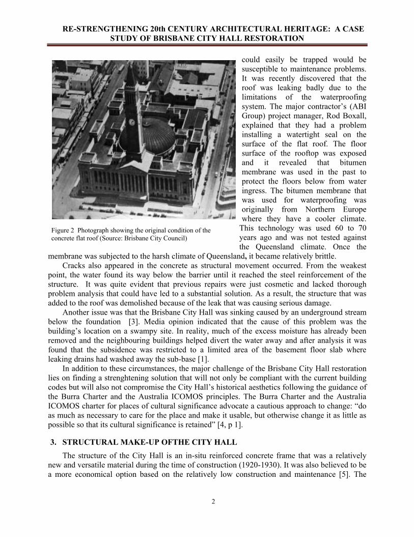
Several problems and their related causes were identified and documented. One major
problem was the ingress of water to the basement of the building due to the leak coming from the
roof. It was claimed that there was a subsequent differential settlement of the foundation where
the water was ponding[3]. A photograph taken a year after Brisbane City Hall opened in 1930,
shows the original flat roof (See Figure 2). That physical condition of being flat where water
Figure 1 Photograph of St Mark’s Campanile (L) & Brisbane City
Hall (R) (Source: A. Cruz & BCC)
RE-STRENGTHENING 20th CENTURY ARCHITECTURAL HERITAGE: A CASE
STUDY OF BRISBANE CITY HALL RESTORATION
2
could easily be trapped would be
susceptible to maintenance problems.
It was recently discovered that the
roof was leaking badly due to the
limitations of the waterproofing
system. The major contractor’s (ABI
Group) project manager, Rod Boxall,
explained that they had a problem
installing a watertight seal on the
surface of the flat roof. The floor
surface of the rooftop was exposed
and it revealed that bitumen
membrane was used in the past to
protect the floors below from water
ingress. The bitumen membrane that
was used for waterproofing was
originally from Northern Europe
where they have a cooler climate.
This technology was used 60 to 70
years ago and was not tested against
the Queensland climate. Once the
membrane was subjected to the harsh climate of Queensland, it became relatively brittle.
Cracks also appeared in the concrete as structural movement occurred. From the weakest
point, the water found its way below the barrier until it reached the steel reinforcement of the
structure. It was quite evident that previous repairs were just cosmetic and lacked thorough
problem analysis that could have led to a substantial solution. As a result, the structure that was
added to the roof was demolished because of the leak that was causing serious damage.
Another issue was that the Brisbane City Hall was sinking caused by an underground stream
below the foundation [3]. Media opinion indicated that the cause of this problem was the
building’s location on a swampy site. In reality, much of the excess moisture has already been
removed and the neighbouring buildings helped divert the water away and after analysis it was
found that the subsidence was restricted to a limited area of the basement floor slab where
leaking drains had washed away the sub-base [1].
In addition to these circumstances, the major challenge of the Brisbane City Hall restoration
lies on finding a strenghtening solution that will not only be compliant with the current building
codes but will also not compromise the City Hall’s historical aesthetics following the guidance of
the Burra Charter and the Australia ICOMOS principles. The Burra Charter and the Australia
ICOMOS charter for places of cultural significance advocate a cautious approach to change: “do
as much as necessary to care for the place and make it usable, but otherwise change it as little as
possible so that its cultural significance is retained” [4, p 1].
3. STRUCTURAL MAKE-UP OFTHE CITY HALL
The structure of the City Hall is an in-situ reinforced concrete frame that was a relatively
new and versatile material during the time of construction (1920-1930). It was also believed to be
a more economical option based on the relatively low construction and maintenance [5]. The
Figure 2 Photograph showing the original condition of the
concrete flat roof (Source: Brisbane City Council)
Arturo Cruz
3
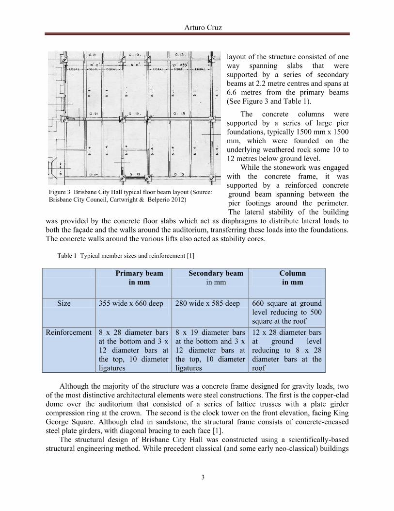
layout of the structure consisted of one
way spanning slabs that were
supported by a series of secondary
beams at 2.2 metre centres and spans at
6.6 metres from the primary beams
(See Figure 3 and Table 1).
The concrete columns were
supported by a series of large pier
foundations, typically 1500 mm x 1500
mm, which were founded on the
underlying weathered rock some 10 to
12 metres below ground level.
While the stonework was engaged
with the concrete frame, it was
supported by a reinforced concrete
ground beam spanning between the
pier footings around the perimeter.
The lateral stability of the building
was provided by the concrete floor slabs which act as diaphragms to distribute lateral loads to
both the façade and the walls around the auditorium, transferring these loads into the foundations.
The concrete walls around the various lifts also acted as stability cores.
Table 1 Typical member sizes and reinforcement [1]
Primary beam
in mm
Secondary beam
in mm
Column
in mm
Size 355 wide x 660 deep
280 wide x 585 deep 660 square at ground
level reducing to 500
square at the roof
Reinforcement 8 x 28 diameter bars
at the bottom and 3 x
12 diameter bars at
the top, 10 diameter
ligatures
8 x 19 diameter bars
at the bottom and 3 x
12 diameter bars at
the top, 10 diameter
ligatures
12 x 28 diameter bars
at ground level
reducing to 8 x 28
diameter bars at the
roof
Although the majority of the structure was a concrete frame designed for gravity loads, two
of the most distinctive architectural elements were steel constructions. The first is the copper-clad
dome over the auditorium that consisted of a series of lattice trusses with a plate girder
compression ring at the crown. The second is the clock tower on the front elevation, facing King
George Square. Although clad in sandstone, the structural frame consists of concrete-encased
steel plate girders, with diagonal bracing to each face [1].
The structural design of Brisbane City Hall was constructed using a scientifically-based
structural engineering method. While precedent classical (and some early neo-classical) buildings
Figure 3 Brisbane City Hall typical floor beam layout (Source:
Brisbane City Council, Cartwright & Belperio 2012)
RE-STRENGTHENING 20th CENTURY ARCHITECTURAL HERITAGE: A CASE
STUDY OF BRISBANE CITY HALL RESTORATION
4
were constructed primarily using the empirical load bearing method of construction, based on
traditions and proven observations, most neo-classical buildings progressively took advantage of
the advancement in scientific and mathematical innovations that introduced the power of
computation into structural analysis.
4. THE PROBLEM
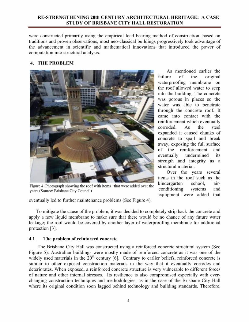
As mentioned earlier the
failure of the original
waterproofing membrane on
the roof allowed water to seep
into the building. The concrete
was porous in places so the
water was able to penetrate
through the concrete roof. It
came into contact with the
reinforcement which eventually
corroded. As the steel
expanded it caused chunks of
concrete to spall and break
away, exposing the full surface
of the reinforcement and
eventually undermined its
strength and integrity as a
structural material.
Over the years several
items in the roof such as the
kindergarten school, air-
conditioning systems and
equipment were added that
eventually led to further maintenance problems (See Figure 4).
To mitigate the cause of the problem, it was decided to completely strip back the concrete and
apply a new liquid membrane to make sure that there would be no chance of any future water
leakage; the roof would be covered by another layer of waterproofing membrane for additional
protection [3].
4.1 The problem of reinforced concrete
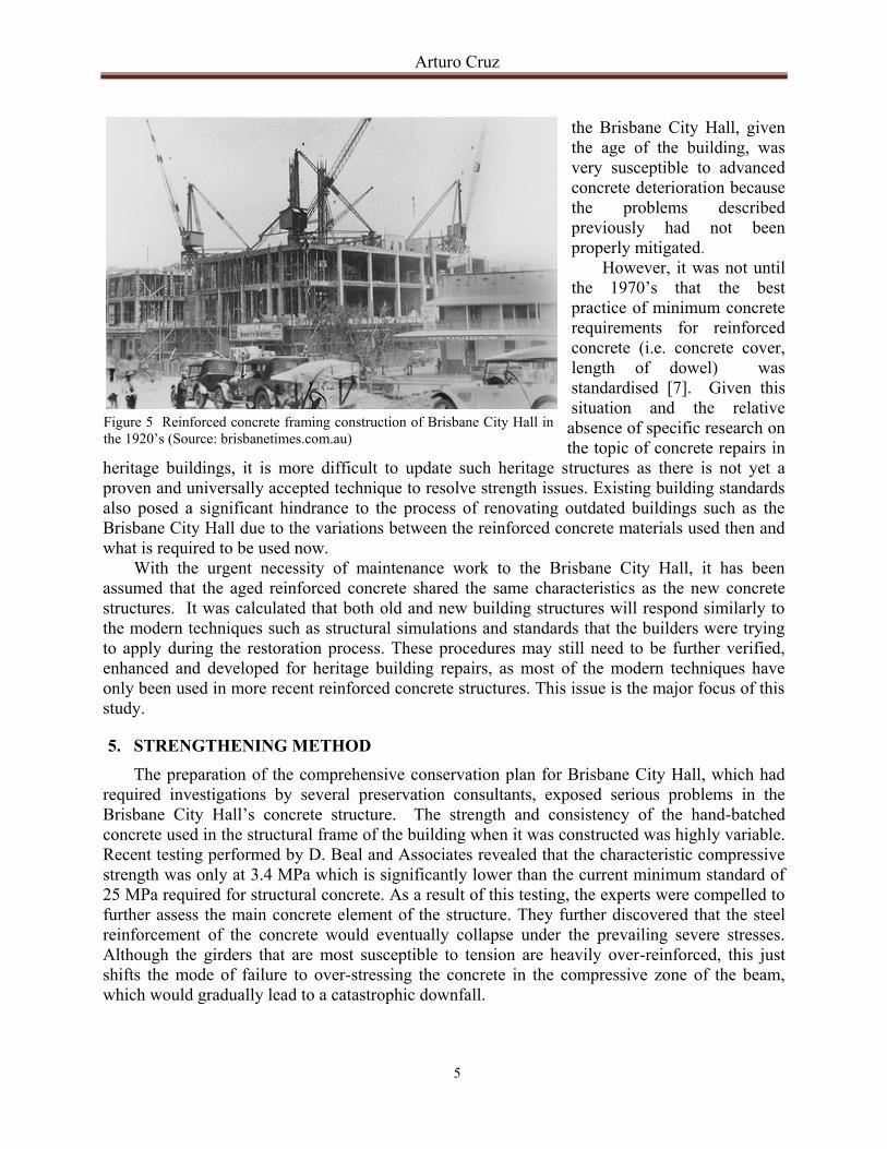
The Brisbane City Hall was constructed using a reinforced concrete structural system (See
Figure 5). Australian buildings were mostly made of reinforced concrete as it was one of the
widely used materials in the 20th
century [6]. Contrary to earlier beliefs, reinforced concrete is
similar to other exposed construction materials in the way that it eventually corrodes and
deteriorates. When exposed, a reinforced concrete structure is very vulnerable to different forces
of nature and other internal stresses. Its resilience is also compromised especially with ever-
changing construction techniques and methodologies, as in the case of the Brisbane City Hall
where its original condition soon lagged behind technology and building standards. Therefore,
Figure 4 Photograph showing the roof with items that were added over the
years (Source: Brisbane City Council)
Arturo Cruz
5
the Brisbane City Hall, given
the age of the building, was
very susceptible to advanced
concrete deterioration because
the problems described
previously had not been
properly mitigated.
However, it was not until
the 1970’s that the best
practice of minimum concrete
requirements for reinforced
concrete (i.e. concrete cover,
length of dowel) was
standardised [7]. Given this
situation and the relative
absence of specific research on
the topic of concrete repairs in
heritage buildings, it is more difficult to update such heritage structures as there is not yet a
proven and universally accepted technique to resolve strength issues. Existing building standards
also posed a significant hindrance to the process of renovating outdated buildings such as the
Brisbane City Hall due to the variations between the reinforced concrete materials used then and
what is required to be used now.
With the urgent necessity of maintenance work to the Brisbane City Hall, it has been
assumed that the aged reinforced concrete shared the same characteristics as the new concrete
structures. It was calculated that both old and new building structures will respond similarly to
the modern techniques such as structural simulations and standards that the builders were trying
to apply during the restoration process. These procedures may still need to be further verified,
enhanced and developed for heritage building repairs, as most of the modern techniques have
only been used in more recent reinforced concrete structures. This issue is the major focus of this
study.
5. STRENGTHENING METHOD
The preparation of the comprehensive conservation plan for Brisbane City Hall, which had
required investigations by several preservation consultants, exposed serious problems in the
Brisbane City Hall’s concrete structure. The strength and consistency of the hand-batched
concrete used in the structural frame of the building when it was constructed was highly variable.
Recent testing performed by D. Beal and Associates revealed that the characteristic compressive
strength was only at 3.4 MPa which is significantly lower than the current minimum standard of
25 MPa required for structural concrete. As a result of this testing, the experts were compelled to
further assess the main concrete element of the structure. They further discovered that the steel
reinforcement of the concrete would eventually collapse under the prevailing severe stresses.
Although the girders that are most susceptible to tension are heavily over-reinforced, this just
shifts the mode of failure to over-stressing the concrete in the compressive zone of the beam,
which would gradually lead to a catastrophic downfall.
Figure 5 Reinforced concrete framing construction of Brisbane City Hall in
the 1920’s (Source: brisbanetimes.com.au)
RE-STRENGTHENING 20th CENTURY ARCHITECTURAL HERITAGE: A CASE
STUDY OF BRISBANE CITY HALL RESTORATION
6
Since the results of the tests proved the building to be significantly below the current
concrete structure requirements, it was imperative that strengthening work should be integrated
into the renovation strategy for the building. The Aurecon group devised a design methodology
to strengthen the floor structure by increasing its capacity with additional reinforcement on the
concrete overlays along the weakened areas. The reinforcement was drilled and was held in place
vertically by the beams of the structure. This method was subjected to an assessment test done
using the prescribed method in AS 3600 (Concrete Structures).
However the non-existence of specific guidance on how to resolve the issue of the existing
low-grade structure that falls more than 20 MPa below the Australian Standard prompted
Aurecon to involve Civil Engineering Professor Peter Dux from the University of Queensland to
verify and validate their proposed strengthening methodology.
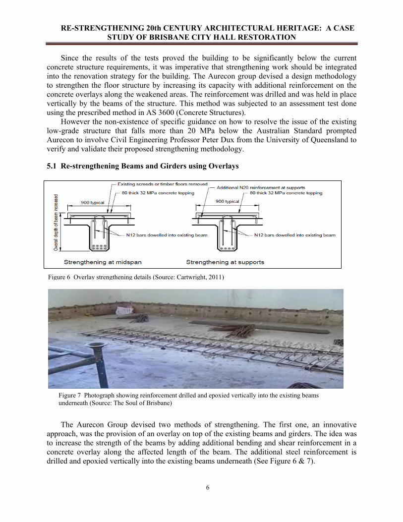
5.1 Re-strengthening Beams and Girders using Overlays
The Aurecon Group devised two methods of strengthening. The first one, an innovative
approach, was the provision of an overlay on top of the existing beams and girders. The idea was
to increase the strength of the beams by adding additional bending and shear reinforcement in a
concrete overlay along the affected length of the beam. The additional steel reinforcement is
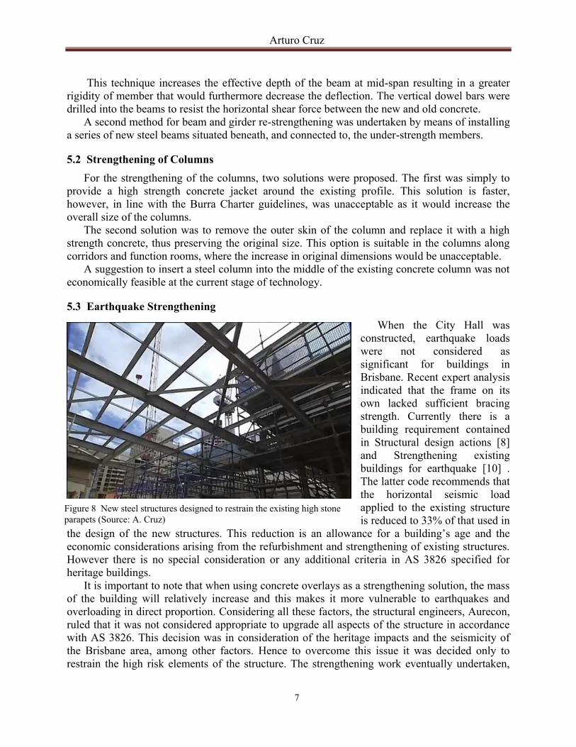
drilled and epoxied vertically into the existing beams underneath (See Figure 6 & 7).
Figure 6 Overlay strengthening details (Source: Cartwright, 2011)
Figure 7 Photograph showing reinforcement drilled and epoxied vertically into the existing beams
underneath (Source: The Soul of Brisbane)
Arturo Cruz
7
This technique increases the effective depth of the beam at mid-span resulting in a greater
rigidity of member that would furthermore decrease the deflection. The vertical dowel bars were
drilled into the beams to resist the horizontal shear force between the new and old concrete.
A second method for beam and girder re-strengthening was undertaken by means of installing
a series of new steel beams situated beneath, and connected to, the under-strength members.
5.2 Strengthening of Columns
For the strengthening of the columns, two solutions were proposed. The first was simply to
provide a high strength concrete jacket around the existing profile. This solution is faster,
however, in line with the Burra Charter guidelines, was unacceptable as it would increase the
overall size of the columns.
The second solution was to remove the outer skin of the column and replace it with a high
strength concrete, thus preserving the original size. This option is suitable in the columns along
corridors and function rooms, where the increase in original dimensions would be unacceptable.
A suggestion to insert a steel column into the middle of the existing concrete column was not
economically feasible at the current stage of technology.
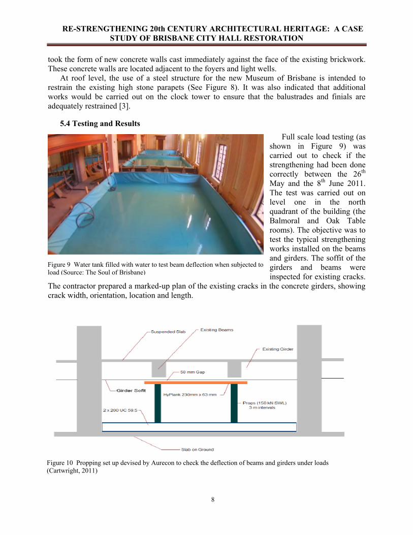
5.3 Earthquake Strengthening
When the City Hall was
constructed, earthquake loads
were not considered as
significant for buildings in
Brisbane. Recent expert analysis
indicated that the frame on its
own lacked sufficient bracing
strength. Currently there is a
building requirement contained
in Structural design actions [8]
and Strengthening existing
buildings for earthquake [10] .
The latter code recommends that
the horizontal seismic load
applied to the existing structure
is reduced to 33% of that used in
the design of the new structures. This reduction is an allowance for a building’s age and the
economic considerations arising from the refurbishment and strengthening of existing structures.
However there is no special consideration or any additional criteria in AS 3826 specified for
heritage buildings.
It is important to note that when using concrete overlays as a strengthening solution, the mass
of the building will relatively increase and this makes it more vulnerable to earthquakes and
overloading in direct proportion. Considering all these factors, the structural engineers, Aurecon,
ruled that it was not considered appropriate to upgrade all aspects of the structure in accordance
with AS 3826. This decision was in consideration of the heritage impacts and the seismicity of
the Brisbane area, among other factors. Hence to overcome this issue it was decided only to
restrain the high risk elements of the structure. The strengthening work eventually undertaken,
Figure 8 New steel structures designed to restrain the existing high stone
parapets (Source: A. Cruz)
RE-STRENGTHENING 20th CENTURY ARCHITECTURAL HERITAGE: A CASE
STUDY OF BRISBANE CITY HALL RESTORATION
8
took the form of new concrete walls cast immediately against the face of the existing brickwork.
These concrete walls are located adjacent to the foyers and light wells.
At roof level, the use of a steel structure for the new Museum of Brisbane is intended to
restrain the existing high stone parapets (See Figure 8). It was also indicated that additional
works would be carried out on the clock tower to ensure that the balustrades and finials are
adequately restrained [3].
5.4 Testing and Results
Full scale load testing (as
shown in Figure 9) was
carried out to check if the
strengthening had been done
correctly between the 26th
May and the 8th
June 2011.
The test was carried out on
level one in the north
quadrant of the building (the
Balmoral and Oak Table
rooms). The objective was to
test the typical strengthening
works installed on the beams
and girders. The soffit of the
girders and beams were
inspected for existing cracks.
The contractor prepared a marked-up plan of the existing cracks in the concrete girders, showing
crack width, orientation, location and length.
Figure 9 Water tank filled with water to test beam deflection when subjected to
load (Source: The Soul of Brisbane)
Figure 10 Propping set up devised by Aurecon to check the deflection of beams and girders under loads
(Cartwright, 2011)
Arturo Cruz
9
The beams and girders in the location where the test was to be executed have heavy duty back
propping placed under them. A gap of 50 mm was provided between the top surface of the
Hyplank and the soffit of the beams and girders in the loading zone. No gap was provided
between the top surface of the Hyplank and the soffit of the girders located at the perimeter of the
loading zone. Figures 10 illustrates the testing method that Aurecon devised to ensure the
strengthening method was correct.
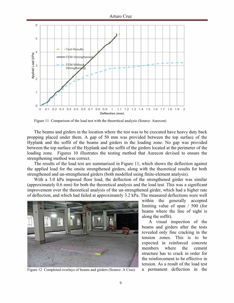
The results of the load test are summarised in Figure 11, which shows the deflection against
the applied load for the onsite strengthened girders, along with the theoretical results for both
strengthened and un-strengthened girders (both modelled using finite-element analysis).
With a 3.0 kPa imposed floor load, the deflection of the strengthened girder was similar
(approximately 0.6 mm) for both the theoretical analysis and the load test. This was a significant
improvement over the theoretical analysis of the un-strengthened girder, which had a higher rate
of deflection, and which had failed at approximately 3.2 kPa. The measured deflections were well
within the generally accepted
limiting value of span / 500 (for
beams where the line of sight is
along the soffit).
A visual inspection of the
beams and girders after the tests
revealed only fine cracking in the
tension zones. This is to be
expected in reinforced concrete
members where the cement
structure has to crack in order for
the reinforcement to be effective in
tension. As a result of the load test
a permanent deflection in the
Figure 11 Comparison of the load test with the theoretical analysis (Source: Aurecon)
Figure 12 Completed overlays of beams and girders (Source: A Cruz)

RE-STRENGTHENING 20th CENTURY ARCHITECTURAL HERITAGE: A CASE
STUDY OF BRISBANE CITY HALL RESTORATION
10
girders of approximately 0.05 mm was recorded.
The full-scale load test demonstrated that the strengthened girders performed in the manner
predicted in the theoretical analysis. Based on the results of the full scale load test it was
considered that the overlay strengthening strategy has been validated for the agreed 3 kPa
imposed floor load. This testing results means that the structural restrengthening upgraded the
structural capacity of the beams and girders of Brisbane City Hall. The concrete overlays (see
Figure 12) enable the structures to comply with the current building legislative requirements
stated on AS 1170 and AS 3600 for building occupancy with an important condition that it will
not allow any physical activities such as rhythmic dancing in the function rooms. The dynamic
effects of those activities would increase the stresses in the floor structures. This condition was
approved by the Brisbane City Council and the structural designer [1].
6. CONCLUSION
Many buildings constructed at the turn of the 20th
century are challenged to meet the demands
of current usage while progressively deteriorating. We are continuously learning new ways to
solve the problems of these modern buildings whether technologically or systematically (while
waiting for the proper solution). A better understanding of this type of building will help to align
the provisions of the current policy and standards. Further monitoring, investigations and
analysis would ensure to enhance the approaches of how to restore this type of building such as
the Brisbane City Hall, a modern heritage building of the 20th
century.
There are several state-of-the-art techniques, both in theory and in practice, in building
assessment and strengthening; however the approach for historic structures requires very
meticulous and comparatively conservative methods. It is not often that a reinforced concrete
structure is considered a historic building, compared to masonry, cast/wrought iron and timber
structures. Due to the concrete decay seen, several techniques for strengthening and repair have
been developed. The case study of the Brisbane City Hall assessment and restoration will
contribute to the opportunity to further explore the restoration of early reinforced concrete.
The World Heritage List has 34 ‘modern heritage’ buildings as compared to 759 overall
cultural heritage properties [12] and continually growing. Modern heritage structures constitute
the bulk of the heritage buildings in Oceania and The Pacific. Most of these buildings are at the
stage of advanced deterioration and require immediate interventions in order to be saved.
However, the restoration requirements for the restoration of ‘modern heritage’ buildings is
different from that of the ‘ancient heritage’ buildings while the policy guidelines are on the early
stage of development for ratification. It is hoped that the content of this case study will
contribute to the debate for enhancing the approaches for the conservation of the 20th
century
architectural heritage.
7. RECOMMENDATION
Further investigations such as mathematical simulation, monitoring and inspection,
experiment and exploration by comparison with other buildings should be done to ensure the
future of the Brisbane City Hall heritage building. The ultimate integrity of the innovative
methods that will come out in the post-restoration phase will provide more sources of relevant
data and information. This will guarantee that this research project will not only document the
important aspects of restoration projects but it will also contribute to the new knowledge
regarding the restoration of 20th
century modern heritage buildings such as Brisbane City Hall.
Arturo Cruz
11
REFERENCES
1. Cartwright, D. and R. Belperio, Saving Brisbane City Hall, in Australian Structural
Engineering Conference 20122012: Perth Western Australia.
2. Department of Environment and Heritage Protection, Q., Brisbane City Hall, 1992.
3. Lofthouse, A.J., Documentary of Brisbane City Hall Three Years Restoration Project, in
The Soul of Brisbane 2011.
4. Australia/ICOMOS. The Burra Charter : The Australian ICOMOS Charter for Places of
Cultural Significance 1999 : with associated guidelines and code on the ethics of co-
existence. [23 p.] 2000; Available from:
http://www.icomos.org/australia/images/pdf/BURRA_CHARTER.pdf.
5. Gebregziabhier, T.T., Durability problems of 20th century reinforced concrete heritage
structures and their restorations, in Civil Engineering2008, Technical University of
Catalonia, Spain: Barcelona.
6. Irwin, R.W., Heritage Engineering - Our Professional Obligation; Practical
Developments in Achieving Our Goals, in Australasian Conference on Engineering
Heritage (2nd: 2000: Auckland, N.Z.)2000, Institution of Professional Engineers New
Zealand: Auckland, N.Z. p. 125-134.
7. Macdonald, S., ICOMOS:20th Century Heritage: Recognition, Protection and practical
challenges, Australia. 2003.
8. AS 1170.4 - 2007, Structural design actions. Part 4: Earthquake actions in Australia.
Standards Australia, 2007.
9. AS 1170.4—2007, Structural design actions. Part 4: Earthquake actions in Australia.
Standards Australia, 2007.
10. AS 3826 - 1998, Strengthening existing buildings for earthquake. Standards Australia,
1998.
11. AS 3826—1998, Strengthening existing buildings for earthquake. Standards Australian,
1998.
12. UNESCO. World Heritage List. 2013 [cited 2013 13th November]; Available from:
http://whc.unesco.org/en/list/.