Embed Size (px)
Citation preview

Patrick Leung School of Engineering Science Simon Fraser University 8888 University Drive Burnaby, BC. V5A 1S6 3/3/08
Re: ENSC 440 Design Specification for the Wall Climbing Robot
Dear Mr. Leung,
Wallybot robotics would like to present the design specification for our prototype Mattoid. Our goal is the design and implementation of a wall-climbing robot for a variety of applications. The design specification describes technical guidelines for Mattoid. Design changes for the production model of Mattoid will be referred to in this specification, but proof-of-concept issues will solely be discussed.
The design decisions, components, and materials used for Mattoid are detailed in the design specification. Testing requirements aligned with our functional specification will also be outlined. In this way, an implemented system can be analyzed for adherence to functionality requirements. Wallybot will follow this design specification as close as possible, but reserves the right to change design elements as necessary to meet the functional specifications.
This document is relevant until April 2008, when the final Mattoid is completed and demonstrated. If you have any questions or concerns about our design specifications, please feel free to contact me by phone at (778) 882-7223 or by e-mail at [email protected].
Sincerely yours,
Daniel Goundar CEO Wallybot Robotics
Enclosure: Design Specification: Wall Climbing Robot

Design Specification: Wall Climbing Robot
Prepared for: Patrick Leung – ENSC 440 Steve Whitmore – ENSC 305 Brad Oldham – TA Jason Lee – TA Prepared by: Curtis Gittens Daniel Goundar Daniel Law Johannes Minor
Date: March 3, 2008 Revision: 1.0
Wallybot – Functional Specification for the Wall Climbing Robot “Mattoid”, © 2008
Executive Summary
Wall-climbing robots are useful solutions in hostile & inaccessible environments, both man-made and naturally occurring. Currently, there is an insatiable market for highly mobile robots with the ability to navigate inhospitable terrain. Wallybot robotics aims to tap this market, staring with the development of its first wall-climbing robot: Mattoid. This design specification document describes design choices pertaining to Mattoid, and justifies those decisions with sound engineering analysis.
At this time, climbing robots have major functional limitations. These limitations often include the use of surface-specific active adhesion systems, and the inability to transfer from horizontal to vertical surfaces. Mattoid will address those inadequacies. A passive adhesive system is currently being developed for use with Mattoid, so an active system, such as vacuum cups, is not necessary and power requirements and weight can be reduced significantly. Mattoid is also designed specifically to allow for a 90° horizontal to vertical transition, through the use of a simple and innovative mechanism. The drive components in Mattoid consist of DC gear motors, and are controlled by a Texas Instruments MSP430 MCU. Optical encoders and rotary potentiometers are part of the sensing system in the control electronics. Each module will be created using a rapid prototyping system involving the Invision SR 3D printer. The modular design of Mattoid allows for expandability both laterally and longitudinally.
This document provides detail on the technical implementation of Mattoid, and a discussion of physical, mechanical, electronic, and power design. Also, testing methods are outlined to validate the functionality of Mattoid, and to find areas where redesign may be necessary. In April 2008, Wallybot Robotics will demonstrate Mattoid, a prototype built robustly on principles of innovation and creativity.
Table of Contents
Executive Summary List of Figures iii Glossary iii 1 Introduction 1
1.1 Scope 1 1.2 Intended Audience 1
2 System Overview 2 3 Physical Design 2
3.1 Compactness 3 3.2 Low profile 3 3.3 Track surface area 4 3.4 Adhesives 4 3.5 Mounting Points for supporting structure 5 3.6 Supporting Structure 6
4 Mechanical Design Specifications 7 4.1 Track pre-tension mechanism 7 4.2 Corner navigation mechanism 8 4.3 Motor power/pulley 9 4.4 Pre-load mechanism 9 4.5 Turning mechanism 10
5 Software Control 12 5.1 Navigation Control 12 5.2 Navigation Input 12 5.3 Feedback Control System 12 5.4 Motor Drive Subsystem 13 5.5 Sensor Data Acquisition Subsystem 15
6 Hardware Control 16 6.1 Optical Encoders and Rotary Potentiometers 16 6.2 Motor control 17
Wallybot – Functional Specification for the Wall Climbing Robot “Mattoid”, © 2008
6.3 Remote control 17

Wallybot – Functional Specification for the Wall Climbing Robot “Mattoid”, © 2008
6.4 Power 18 7 Power Design 19
7.1 Microcontroller 19 7.2 Encoders 20 7.3 Gear Motors 20 7.4 Miscellaneous 20
8 Test Methodology 21 8.1 Test Case I: Basic Climb 21 8.2 Test Case II: 90° Transition 22 8.3 Test Case III: 45° Turn 22
9 Conclusion 24 10 References 25

iii
List of Figures Figure 1: Conceptual diagram of the module and control electronics layout 2 Figure 2: A single module: Exploded View 3 Figure 3: Center of mass of a single Mattoid module 4 Figure 4: Mounting points on male chassis piece 5 Figure 5: Mounting points on female chassis piece 5 Figure 6: Supporting structure connecting two modules 6 Figure 7: Single Assembled Module 7 Figure 8: Track Pre-tension Mechanism 7 Figure 9: Force Diagram for Corner Transition 8 Figure 10: Degrees of freedom in the joint between module rows 8 Figure 11: Ninety Degree inside Corner Transition 9 Figure 12: Moments with and without pre-load spring 10 Figure 13: A two-module arrangement, with supporting structure and pre-load leaf spring 10 Figure 14: Turn geometry of a two-module Mattoid assembly 11 Figure 15: Hierarchical view of Control Software Functionality 12 Figure 16: Software Feedback Control System 13 Figure 17: Motor Drive Subsystem 14 Figure 18: Timer B in up mode -1 [1] 14 Figure 19: Timer B in up mode- 2 [1] 15 Figure 20: PWM signal for CCR1 [1] 15 Figure 21: Bourns optical encoder [2] 16 Figure 22: Sensor layout and feedback for the Mattoid Prototype System 17 Figure 23: Motor drive circuit 17 Figure 24: A lightweight, appropriately sized sheet metal tin [3] 18 Figure 25: GM14a gear motor [4] 20 Figure 26: Two modules [1x2] 21 Figure 27: Six modules [3x2] 23
Glossary ADC Analog to Digital Converter Aspect Ratio The ratio between horizontal and vertical dimensions of an object or feature CCR Capture/Compare Register ISR Interrupt Service Routine Mattoid The cutting edge prototype in the field of wall-climbing robotsMCU Microcontroller Unit Minimal slip An optimally minimal loss of traction PPR Pulses Per Revolution – Encoder Accuracy Rating PWM Pulse Width Modulation Rapid Prototyping Automation formation of 3D shapes using a layered printing technique SDP/SI Stock Drive Products/Sterling Instrument Shim A wedge shaped piece of material used to create spacing or level an object
Wallybot – Functional Specification for the Wall Climbing Robot “Mattoid” © 2008
Turning radius The radius of the smallest circular turn possible

1
Wall Climbing Robot
1 Introduction Wallybot Robotics is a research based organization that works towards creating technology for use in industry-ready robots that solve a variety of real world problems. Our goal is to develop small robots that can navigate man made environments, without being impeded by walls and corners.
1.1 Scope
This document describes the design specifications for the Mattoid wall climbing robot prototype. It focuses on design of the prototype and only briefly outlines some of the production model design specifications.
1.2 Intended Audience
Wallybot – Functional Specification for the Wall Climbing Robot “Mattoid” © 2008
The target audience includes the design engineers and project management at Wallybot Robotics. Management and developers should consult this document as a guide to implementation of the Mattoid proof of concept prototype. Specifically, the electronic and mechanical design teams can find detail design descriptions to aid in prototype development. Project management may use this document as a reference when measuring implementation progress of Mattoid.
2
Wallybot – Functional Specification for the Wall Climbing Robot “Mattoid”, © 2008
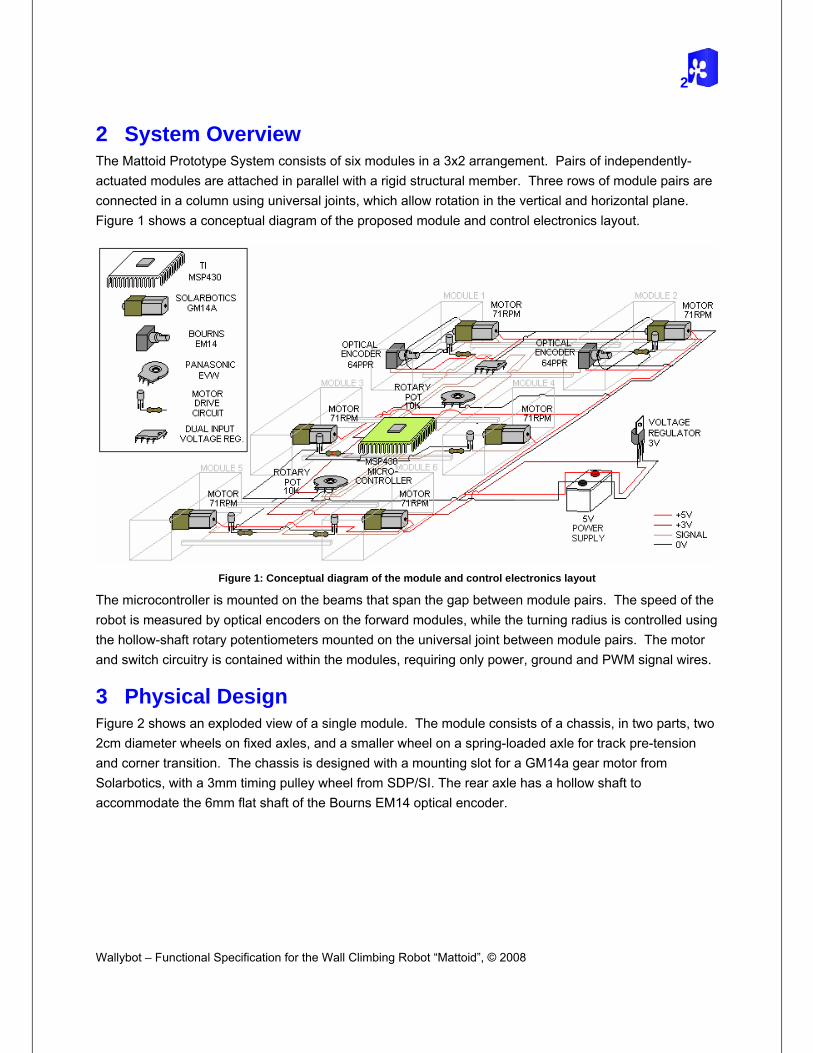
2 System Overview The Mattoid Prototype System consists of six modules in a 3x2 arrangement. Pairs of independently-actuated modules are attached in parallel with a rigid structural member. Three rows of module pairs are connected in a column using universal joints, which allow rotation in the vertical and horizontal plane. Figure 1 shows a conceptual diagram of the proposed module and control electronics layout.
Figure 1: Conceptual diagram of the module and control electronics layout
The microcontroller is mounted on the beams that span the gap between module pairs. The speed of the robot is measured by optical encoders on the forward modules, while the turning radius is controlled using the hollow-shaft rotary potentiometers mounted on the universal joint between module pairs. The motor and switch circuitry is contained within the modules, requiring only power, ground and PWM signal wires.
3 Physical Design
Figure 2 shows an exploded view of a single module. The module consists of a chassis, in two parts, two 2cm diameter wheels on fixed axles, and a smaller wheel on a spring-loaded axle for track pre-tension and corner transition. The chassis is designed with a mounting slot for a GM14a gear motor from Solarbotics, with a 3mm timing pulley wheel from SDP/SI. The rear axle has a hollow shaft to accommodate the 6mm flat shaft of the Bourns EM14 optical encoder.

3
Figure 2: A single module: Exploded View
3.1 Compactness
A single Mattoid module has a 3D footprint of approximately 7cm x 4cm x 3.5cm. Maintaining a small size allowed flexibility when selecting the remainder of components; most notably, the tread width and motor strength. Each compact module will contain all motors and sensors needed for operation of that module, as well as mounting points for supporting structure. A compact module has significant flexibility advantages when dealing with an expanded system.
3.2 Low profile
Wallybot – Functional Specification for the Wall Climbing Robot “Mattoid” © 2008
Maintaining contact with a vertical surface requires a low center of mass. The module has a low aspect ratio, and is designed to keep the majority of the mass in close proximity to the climbing surface. The force due to gravity creates a moment about the lowest point of contact between the wall and the climbing surface. This moment is minimized by the low center of mass. This design feature can be seen in the SolidWorks rendering in Figure 3

4
Wallybot – Functional Specification for the Wall Climbing Robot “Mattoid”, © 2008
Figure 3: Center of mass of a single Mattoid module
Also, the center of mass of the module is centered over the track. This is important for lateral stability.
3.3 Track surface area
The amount of track that makes contact with the vertical surface is critical to the overall ability of Mattoid to climb walls. The length and width of the track contact area must be optimized for minimal slip, given the desired turning radius, while the contact area must remain large enough to provide the adhesion force required to support the module and control electronics. Figure 3 also shows the 4cm x 1cm track surface area that a single module will have adhered to a vertical surface.
3.4 Adhesives
Mattoid is designed to use an advanced passive dry adhesive for its track surface. Polymer microfabrication techniques can be used to develop directional adhesives, which bond firmly to surfaces when the force is applied perpendicular to the contact surface, but take very little energy to peel off at some angle. Due to time constraints, the research group developing this polymer adhesive may not have

5
a reliable product completed on the Mattoid prototype testing schedule. Therefore, multiple replacement adhesive systems have been purchased for use with the prototype. Those systems include a 3M double-sided tape, a Velcro winding, and “sticky putty”. Testing will be performed with these adhesives to find an appropriate replacement.
3.5 Mounting Points for supporting structure
Each Mattoid module provides mounting points for a supporting structure. For infinite expandability, symmetrical mounting points are provided on both sides of the chassis. The design of these mounting points takes other design features into consideration. Figure 4: Mounting points on male chassis pieceFigure 4 indicates the features on the side of the chassis without the drive belt.
Figure 4: Mounting points on male chassis piece
The spacing between parallel crossbeams is 30mm. The design is modified to accommodate a drive belt on the other side. Figure 5 shows the modified support, which provides a channel for the drive belt to run through.
Wallybot – Functional Specification for the Wall Climbing Robot “Mattoid” © 2008
Figure 5: Mounting points on female chassis piece

6
Wallybot – Functional Specification for the Wall Climbing Robot “Mattoid”, © 2008
By providing compatible mounting joints on either side of the chassis, Mattoid becomes as expandable as necessary.
3.6 Supporting Structure
The expandability of Mattoid is dependent upon the supporting structure which joins the individual modules. Hollow aluminum rods (5/32” 0.014 wall) are being used as the module connections. The length of these rods is approximately 10cm. Modifications to this specified length will be considered if testing indicates a need.
These rods are lightweight and rigid, and their contribution to the overall weight of an assembled system is minimal.
Figure 6: Supporting structure connecting two modules
The width and spacing of the two supporting structure is chosen to accommodate the control electronics.

7
4 Mechanical Design Specifications
Figure 7: Single Assembled Module
4.1 Track pre-tension mechanism
The adhesive track requires tension to stay engaged with the drive wheel. In addition to the two base wheels on fixed axles, a third wheel is mounted on a spring axle to hold the track tight. The exploded view in Figure 2 shows the track pre-tension system assembly.
Springs are placed in the guiding channels in the chassis, and plungers on the two-part axle compress the spring when the distance between the fixed and compliant axles is decreased. Figure 8 shows a cross sectional view of this mechanism.
Figure 8: Track Pre-tension Mechanism
Wallybot – Functional Specification for the Wall Climbing Robot “Mattoid” © 2008
8
Wallybot – Functional Specification for the Wall Climbing Robot “Mattoid”, © 2008
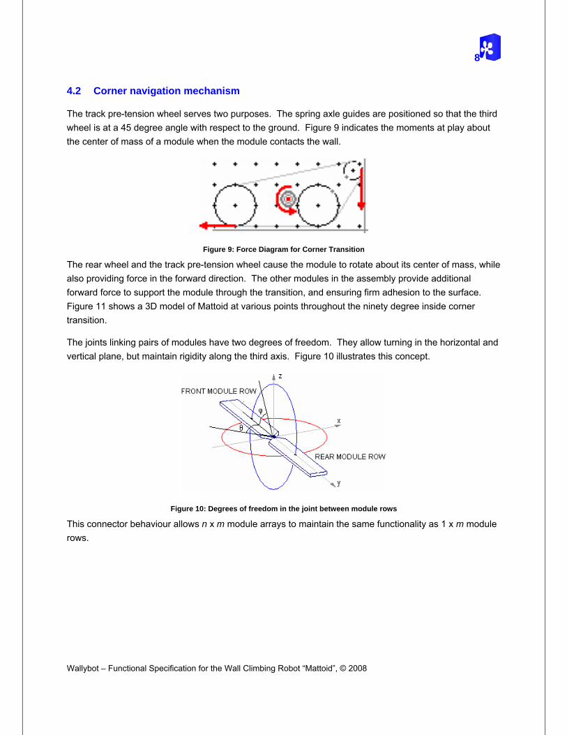
4.2 Corner navigation mechanism
The track pre-tension wheel serves two purposes. The spring axle guides are positioned so that the third wheel is at a 45 degree angle with respect to the ground. Figure 9 indicates the moments at play about the center of mass of a module when the module contacts the wall.
Figure 9: Force Diagram for Corner Transition
The rear wheel and the track pre-tension wheel cause the module to rotate about its center of mass, while also providing force in the forward direction. The other modules in the assembly provide additional forward force to support the module through the transition, and ensuring firm adhesion to the surface. Figure 11 shows a 3D model of Mattoid at various points throughout the ninety degree inside corner transition.
The joints linking pairs of modules have two degrees of freedom. They allow turning in the horizontal and vertical plane, but maintain rigidity along the third axis. Figure 10 illustrates this concept.
Figure 10: Degrees of freedom in the joint between module rows
This connector behaviour allows n x m module arrays to maintain the same functionality as 1 x m module rows.

9
a b c
Figure 11: Ninety Degree inside Corner Transition
4.3 Motor power/pulley
The motor is mounted in a housing structure in the middle of the module between the two wheels. A timing belt is used to transfer power from the motor to the driving wheel. A gear head is attached to the flatted shaft of the motor, using a rectangular key. The rear driving wheel, seen in Figure 2, has a built in 10-tooth gear to match the gear head on the motor. To provide tension in the belt, the motor housing is built with clearance for shims. The final belt assembly can be seen in Figure 7. The drive belt runs freely through the cross-beam mounting structure.
4.4 Pre-load mechanism
When a module adheres to a vertical surface, the module will tend to rotate about the lowest point on the adhesive track. Although the module was designed with a low aspect ratio, as described in Section 3.2, the center of mass is some distance away from the wall, and gravity will therefore contribute to the moment of the assembly about the axis of rotation. To increase Mattoid’s reliability, a pre-load leaf spring is added to each two-module pair. The leaf spring moves the lowest wall contact point farther down, minimizing the effect of the moment as a result of gravity.
Wallybot – Functional Specification for the Wall Climbing Robot “Mattoid” © 2008
Also, the spring action will create some moment about the center of mass of the module, contributing to a stronger contact between the top of the adhesive track and the wall. These concepts are illustrated in the force diagrams of Figure 12.

10
Wallybot – Functional Specification for the Wall Climbing Robot “Mattoid”, © 2008
Figure 12: Moments with and without pre-load spring
This leaf spring will be mounted on the supporting structure between adjacent modules. The model in Figure 13 shows one possible implementation of the pre-load leaf spring.
Figure 13: A two-module arrangement, with supporting structure and pre-load leaf spring
This particular implementation takes advantage of the two crossbeams to provide adequate spring deformation. Static and dynamic analysis is needed to determine the optimal leaf-spring length, and the optimal spring force.
4.5 Turning mechanism
Turning is achieved by varying speed the speed of each individual module. In the simplest case, a turning radius of infinity, all modules move at identical speeds. When the turning radius is finite, the velocities must be adjusted so that a circular path is traced.
Tangential velocity is related to angular velocity by the following relationship:

11
vT=ω·r
Therefore, based on the geometry in Figure 14:
turn
turn
outside
outside
inside
inside
rv
rv
rv
==
2drr turninside −=
2drr turnoutside +=
⎟⎟⎠
⎞⎜⎜⎝
⎛−=
turnturninside r
dvv2
1 ⎟⎟⎠
⎞⎜⎜⎝
⎛+=
turnturnoutside r
dvv2
1
The required inside and outside velocities can be easily calculated based on velocity and desired speed and turn radius.
Figure 14: Turn geometry of a two-module Mattoid assembly
Wallybot – Functional Specification for the Wall Climbing Robot “Mattoid” © 2008
An adhesive track that is long or wide will have significant slip when small radius turns are attempted. To minimize slip, the individual modules will be small relative to the turning radius of the entire robot assembly. Also, the adhesive track will be made of some sponge or other compliant material so that minimal deformation will not result in failure of the adhesive.

12
Wallybot – Functional Specification for the Wall Climbing Robot “Mattoid”, © 2008
5 Software Control The Texas Instruments MSP430F169 microcontroller has been chosen for the control platform for the Mattoid prototype system [1]. Figure 15 shows a hierarchical division of functionality of the control software behind Mattoid.
Figure 15: Hierarchical view of Control Software Functionality
5.1 Navigation Control
Using Navigation Input the Mattoid software will interact with the Feedback Control System in Figure 15 to achieve desired system behaviour. At regular intervals, monitored by Timer A, calculations will be made and the desired motor speeds and potentiometer angles will be passed to the Feedback Control System.
5.2 Navigation Input
Navigation input in this document refers to high level directives such as go, stop, turn right and turn left that are intended for Mattoid. The Mattoid prototype will retrieve this input from a push button control module or from the MSP430F169 built-in RAM. For production iterations of Mattoid, sensory input can be used to achieve complete autonomous behaviour.
5.3 Feedback Control System
Smooth operation of Mattoid requires feedback control to guarantee that desired motor speed and power, and robot turning radius are achieved. The feedback control system, shown in Figure 16 takes input from

13
the optical encoders and rotary potentiometers and makes adjustments to the power supplied to motors. It also takes desired speeds and angles as input from the Navigation Control module and translates these values into power duty cycles for the motors and to a digital representation of the desired potentiometer angles.
Figure 16: Software Feedback Control System
5.4 Motor Drive Subsystem
Wallybot – Functional Specification for the Wall Climbing Robot “Mattoid” © 2008
The Mattoid prototype model will feature six individually actuated modules. Module and system speed will be determined by the amount of power supplied to actuators. Figure 17 shows an overview of the Motor drive subsystem, which uses an on-chip hardware timer module, Timer B, and PWM to vary motor input power supplied to each module. Timer B has seven independently configurable CCRs, each having access to an output pin. Using the timer B compare mode allows for PWM signals to be generated directly by the timer module without interrupting the main program execution and freeing up valuable CPU time.

14
Wallybot – Functional Specification for the Wall Climbing Robot “Mattoid”, © 2008
Figure 17: Motor Drive Subsystem
Timer B is 16-bit timer with configurable length, TBCLO, and clock dependent count frequency, fTB. Choosing count length, TBCLO = TBmax = 216-1, allows for 216 possible pulse widths comfortably exceeding motor power control resolution requirements. Using the on-chip peripheral clock, SMCLK, the timer count frequency will be approximately 5 MHz (the chip local oscillator is subject to small variations in frequency at different operating temperatures).
Timer B will continuously count from 0 to TBCL0 at a frequency of fTB = TBT1 as shown in Figure 18 and
Figure 19.
Figure 18: Timer B in up mode -1 [1]

15
Figure 19: Timer B in up mode- 2 [1]
The Timer will function with six CCRs configured for Compare mode. In compare mode an action or event is automatically generated when the timer B count is equal to the value stored in a compare register. For the Mattoid motor drive subsystem the CCR registers will store the pulse width in timer counts and will directly manipulate output pins that are connected to the motor drive circuitry in Figure 23. Figure 20 shows the waveform generated from compare mode with CCR1 storing a value TBCL1. TBCL1 can range from 0h for maximum power to TBCL0 for zero power provided to the motors. The motor drive subsystem therefore requires little operation overhead after initialization because the CCR registers only need modifying when a change in motor power is necessary. Also PWM output requires no direct CPU time because this is managed by the timer B module.
Figure 20: PWM signal for CCR1 [1]
5.5 Sensor Data Acquisition Subsystem
Mattoid will use optical encoders and rotary potentiometers to determine speed and orientation when in motion. This section describes the software portion of sensory data acquisition.
5.5.1 Optical Encoders
Wallybot – Functional Specification for the Wall Climbing Robot “Mattoid” © 2008
The speed of the Mattoid assembly is measured by two optical encoders on the forward modules shown in Figure 1. The optical encoders each generate 64 pulses per revolution, with each pulse triggering a parallel port interrupt [2]. Due to the timing sensitive nature of the Mattoid control algorithm the motor, a “minimum handler” technique will be used for all interrupt servicing. The parallel port ISR will only accumulate encoder pulses in globally accessible variables. The control algorithm can accumulate these values to measure distance, and differentiate the readings with respect to time to measure velocity and acceleration.

16
Wallybot – Functional Specification for the Wall Climbing Robot “Mattoid”, © 2008
5.5.2 Rotary Potentiometers
Measurements from the rotary potentiometers will be obtained using the 12-bit ADC on the MSP430F169. The ADC12 module will be configured to automatically sample and convert a sequence of analog input channels and interrupt the CPU when these conversions are finished. Once again a “minimum handler” ISR will be used in which the ADC12 measurements will be copied to globally accessible variables. A sequence measurement by the ADC12 module will be triggered directly by Timer A. This implementation scheme also requires little CPU time after initialization.
6 Hardware Control
6.1 Optical Encoders and Rotary Potentiometers
The first component of the control design is reading the speed of the front pair of modules, comparing that to the desired speed, and then adjusting the supplied power as necessary. Speed sensing is performed using a Bourns optical encoder from the EM14 family, illustrated in Figure 21. An optical encoder has been chosen so that the effect of bouncing from a contact encoder is eliminated. This particular optical encoder has been chosen for its small size (1x1x3 cm) and its ideal resolution (64 PPR) [2].
Figure 21: Bourns optical encoder [2]
The desired speed for the second and third pair of modules will be determined by the speed of the first pair of modules and by the position of the second and third modules with respect to the first. Hollow shaft rotary potentiometers are used to measure the angle between modules. Two analog to digital conversions are required. The MSP430F169 can handle eight ADC pins.
For travel in a straight line, the angle between adjacent rows is 0 degrees, and all modules are driven at the same speed. To turn around some point, the speed of each module in the first row is controlled as described in Section 4.5, and the power supplied to following rows is modified based on the desired angles.
A 10KΩ Panasonic rotary potentiometer is mounted on the joint between pairs to determine the bend. This part has again been chosen for size and for the fact that it has a hollow shaft which accommodates mounting to the custom made joint. Figure 22: Sensor layout and feedback for the Mattoid Prototype System shows the sensor layout and feedback associated with each of the sensors.

17
Figure 22: Sensor layout and feedback for the Mattoid Prototype System
6.2 Motor control
The output of the microcontroller is at 3.3V, and the motors are rated at 4.8 – 6V. PWM control using a digital output from the microcontroller is accomplished using the motor control circuit of Figure 23. The output is active-high.
Figure 23: Motor drive circuit
6.3 Remote control
Wallybot – Functional Specification for the Wall Climbing Robot “Mattoid” © 2008
The user interface for the prototype is a crude hand-held wired remote with four pushbuttons. The pushbuttons are mounted on a lightweight, appropriately sized sheet metal tin, such as the one in Figure 24. The robot will recognize four commands: go, stop, turn left, and turn right.

18
Wallybot – Functional Specification for the Wall Climbing Robot “Mattoid”, © 2008
Figure 24: A lightweight, appropriately sized sheet metal tin [3]
6.4 Power
The system requires a 5V power supply, capable of supplying at minimum 270mA of current. A low dropout voltage regulator will be used to supply the microcontroller, which requires 1.8 – 3.6V supply. A 5V to 3.3V voltage regulator from Texas Instruments suits this purpose. One will be used to supply the microcontroller and all passive electronic components, and a multiple input/multiple output voltage regulator chip is used as an interface between the 5V optical encoder digital output pin and the 3.3V microcontroller digital input pin.
19
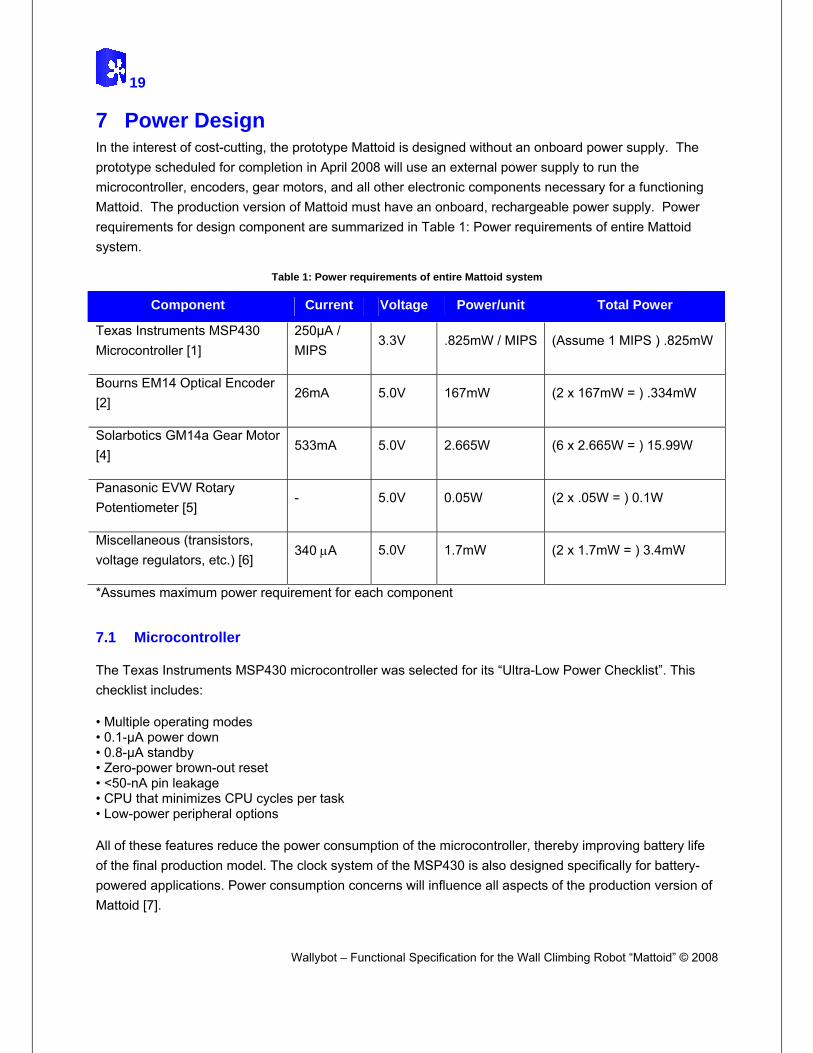
7 Power Design In the interest of cost-cutting, the prototype Mattoid is designed without an onboard power supply. The prototype scheduled for completion in April 2008 will use an external power supply to run the microcontroller, encoders, gear motors, and all other electronic components necessary for a functioning Mattoid. The production version of Mattoid must have an onboard, rechargeable power supply. Power requirements for design component are summarized in Table 1: Power requirements of entire Mattoid system.
Table 1: Power requirements of entire Mattoid system
Component Current Voltage Power/unit Total Power
Texas Instruments MSP430 Microcontroller [1]
250µA / MIPS
3.3V .825mW / MIPS (Assume 1 MIPS ) .825mW
Bourns EM14 Optical Encoder [2]
26mA 5.0V 167mW (2 x 167mW = ) .334mW
Solarbotics GM14a Gear Motor [4]
533mA 5.0V 2.665W (6 x 2.665W = ) 15.99W
Panasonic EVW Rotary Potentiometer [5]
- 5.0V 0.05W (2 x .05W = ) 0.1W
Miscellaneous (transistors, voltage regulators, etc.) [6]
340 µA 5.0V 1.7mW (2 x 1.7mW = ) 3.4mW
*Assumes maximum power requirement for each component
7.1 Microcontroller
The Texas Instruments MSP430 microcontroller was selected for its “Ultra-Low Power Checklist”. This checklist includes:
• Multiple operating modes • 0.1-µA power down • 0.8-µA standby • Zero-power brown-out reset • <50-nA pin leakage • CPU that minimizes CPU cycles per task • Low-power peripheral options
Wallybot – Functional Specification for the Wall Climbing Robot “Mattoid” © 2008
All of these features reduce the power consumption of the microcontroller, thereby improving battery life of the final production model. The clock system of the MSP430 is also designed specifically for battery-powered applications. Power consumption concerns will influence all aspects of the production version of Mattoid [7].

20
Wallybot – Functional Specification for the Wall Climbing Robot “Mattoid”, © 2008
7.2 Encoders
Bourns optical encoders from the EM14 series will be used for speed and position control. This series has a low current draw, small size, and runs on a 5V source. Signals from optical encoders do not need to be de-bounced, which increases reliability, and eliminates the need for debounce software or circuitry. Any extra power draws are being limited to allow for Mattoid to be a battery-powered production model [2].
7.3 Gear Motors
The Solarbotics GM14a gear motors are chosen due to their high torque characteristics given the small package, and the relatively low current draw the motors possess. Despite having such a low current draw, assuming stall current, an individual gear motor will draw as much as 2.665W. This value is too large to be transferred into a battery-powered application. In order to limit the power draw, the control circuitry will limit the motors to have a current draw of under 100mA. By doing this, a production Mattoid will be able to stay battery operated, and not require an external power supply used by the prototype [4].
Figure 25: GM14a gear motor [4]
7.4 Miscellaneous
Other miscellaneous circuitry in Mattoid was selected to minimize power draw. An example of this is the voltage regulator used for the optical encoders output. The Texas Instruments TPS73xx series possesses a low sleep state and quiescent current. These values are in the micro range, and become negligible relative to the larger power requirement of the gear motors [6].
21
8 Test Methodology The Mattoid prototype system will require testing of the various subsystems involved with completing the three test cases outlined in the functional specification (Basic Climb, 90° Transition, 45° Turn). Drive system functionality, adhesive strength, and support structure robustness will be thoroughly analyzed. The three test cases are described below:
8.1 Test Case I: Basic Climb
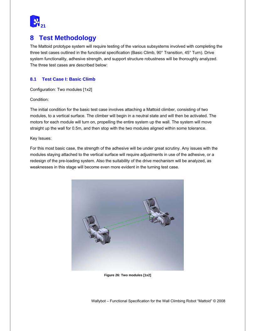
Configuration: Two modules [1x2]
Condition:
The initial condition for the basic test case involves attaching a Mattoid climber, consisting of two modules, to a vertical surface. The climber will begin in a neutral state and will then be activated. The motors for each module will turn on, propelling the entire system up the wall. The system will move straight up the wall for 0.5m, and then stop with the two modules aligned within some tolerance.
Key Issues:
For this most basic case, the strength of the adhesive will be under great scrutiny. Any issues with the modules staying attached to the vertical surface will require adjustments in use of the adhesive, or a redesign of the pre-loading system. Also the suitability of the drive mechanism will be analyzed, as weaknesses in this stage will become even more evident in the turning test case.
Wallybot – Functional Specification for the Wall Climbing Robot “Mattoid” © 2008
Figure 26: Two modules [1x2]

22
Wallybot – Functional Specification for the Wall Climbing Robot “Mattoid”, © 2008
8.2 Test Case II: 90° Transition
Configuration: Two modules [1x2]
Condition:
Initially, Mattoid will be placed on a horizontal surface a short distance from a 90° transition (at least far enough for the system to reach top speed). From the neutral state, Mattoid will be activated and will have both modules make contact with the wall simultaneously. At that point the transition section of the tread will make contact with the vertical surface, and the system should transfer from a horizontal to a vertical orientation. Mattoid will continue to ascend the wall for the same 0.5m as in test case I.
Key Issues:
The positioning of the tread-tensioning wheel is a major issue in this test. If a module is unable to hit the vertical surface with its tread-tensioning wheel, and then have the transition tread make contact, an alteration in the placement of the wheels will be required. Also, the torque supplied by the motor will be analyzed closely; without sufficient torque the 90° transition will be unfeasible for Mattoid. Assuming necessary torque is produced by the motor; the supporting structure will be checked thoroughly after the test to ensure that it can handle transition forces.
8.3 Test Case III: 45° Turn
Configuration: Six modules [3x2]
Condition:
The final test case will use a Mattoid assembly consisting of 6 modules in a 3x2 array. Mattoid will be attached vertically to a surface, perpendicular to the horizontal surface below. Once Mattoid is activated, it will begin a curved ascent of the vertical surface. The system will be following a path with radius of curvature of 1.0m. Mattoid will complete a 45° arc before returning back to its neutral state on the surface.
Key Issues:
The control system employed in Mattoid will be evaluated thoroughly in this test. Whether individual wheel speed is maintained is based on the effectiveness of the control system. Since varying wheel speeds is the crux of a vertical turn, a flawed control system will be redesigned for optimal turning capabilities. Also, the sensing electronics (i.e. rotary potentiometer), will be checked to see whether it has the necessary resolution.

23
Figure 27: Six modules [3x2]
Wallybot – Functional Specification for the Wall Climbing Robot “Mattoid” © 2008
24
Wallybot – Functional Specification for the Wall Climbing Robot “Mattoid”, © 2008
9 Conclusion
Wallybot robotics aims to tap the burgeoning market of wall-climbing robots with Mattoid. The design specifications described in this document provide the basis for an intelligent, innovative, and multipurpose robotic system. The design solutions proposed meet the functional specifications earlier laid out by Wallybot. Components and designs were decided upon based on the two main constraints of cost and functionality. The capabilities of Mattoid will be demonstrated using a prototype system in April 2008.

25
10 References [1] Texas Instruments Mixed Signal Products, MSP430x1xx Family User’s Guide, Texas Instruments, 2004.
[2] Bourns EM14 Rotary Optical Encoder. http://www.bourns.com/pdfs/em14.pdf, 2008.
[3] Altoids – Wikipedia. http://en.wikipedia.org/wiki/Image:Altoidstins1.jpg, 2008.
[4] GM14a- 298:1 Mini Metal Gear Motor; Products; Solarbotics. http://www.solarbotics.com/products/gm14a/, 2008.
[5] Panasonic EVWAE4001B14. (Digikey datasheet) http://rocky.digikey.com/weblib/Panasonic/Web%20data/EVWAE4001B14.pdf, 2003.
[6] TI SLVS124F. http://focus.ti.com/lit/ds/slvs124f/slvs124f.pdf, 1999.
Wallybot – Functional Specification for the Wall Climbing Robot “Mattoid” © 2008
[7] MSP430 series microcontroller. http://focus.ti.com/lit/ml/slab034m/slab034m.pdf, 2007.