Embed Size (px)
Citation preview

P O Box 3097 (360) 687-7668 Online wwwEkEngineeringnet
Battle Ground WA 98604 (360) 687-7669 Fax E-Mail DavidEkEngineeringnet
Northwest Cascade Inc June 16 2010 Attn John Nutt P O Box 73399 Puyallup WA 98373
Re Engineering Design and Calculations for the Precast Concrete Tank (Model BZP-1200)
Dear John
At your request we hereby provide a design and calculations for the precast concrete pump tank (Model BZP-1200) The design is based on the requirements of the 246-272C WAC for on-site sewage system tanks We recommend the following
1 Construct the tank as per the minimum requirements listed on the design summary pages 1-3 of the attached report Minimum concrete and reinforcement properties concrete cover tank dimensions and reinforcement spacing are included
2 Data used in the finite element analysis program spWalltrade for the design of the side walls end walls and lid are in Appendices A B and C respectively
3 Refer to the attached drawings on pages 4 and 5 of the tank for complete construction details and installation instructions
If you have any questions please call 360-687-7668
Sincerely
David R Nylund PE
EK ENGINEERING PO BOX 3097 BATILE GROUND WA 98604
I PG 1
CONCRETE TANK DESIGN
PROJECT DESCRIPTION BZP-1200 PRECAST CONCRETE TANK PROJECT FOR NORTHWEST CASCADE INC
DATE 6162010
DESIGN CRITERIA I DEFINITIONS
SIDE WALL DIMENSIONS
HEIGHT 5292 ft LENGTH 7917 ft
THICKNESS 25 in CONCRETE COVER
(MINMAX) 10625 in 14375 in
END WALL DIMENSIONS HEIGHT 5292 ft LENGTH 5792 ft
THICKNESS 25 in CONCRETE COVER
(MINMAX) 10625 in 14375 in
CONCRETE PROPERTIES COMPRESSIVE STRENGTH I 4500 Ipsi
WEIGHT I 150 Ipcf
STEEL REINFORCEMENT PROPERTIES STEEL STRENGTH1 60 1ksi STEEL ELASTICITYI 29000 Iksi
SOIL PROPERTIES
COVER DEPTH 3 ft GROUND WATER DEPTH 3 ft
WEIGHT 110 ipcf SOIL FRICTION ANGLE PHI 32 deg
LID DIMENSIONS
LENGTH 7917 ft WIDTH 5792 ft
THICKNESS 4 in CONCRETE COVER
(MINMAX) 225 in 275 in
The equivalent fluid pressure assuming fully saturated soil is calculated as follows
P =WgtSOIL H + (WgtSOIL - WgtH20) K H
K =[1-sin(phi)] [1+sin(beta)] =047 (passive) (Angle of slope beta is assumed to be 0 degrees)
P = [ 624 + (11 0 - 624) 04 7 ] H
P == 85 Ibft3 H
The assumptions for the surchage on the saturated soil below the 3 ft of dry soil cover are included in the Design AssumptionsNotes below
DESIGN ASSUMPTIONSNOTES Wall dimensions (shown in the charts above) are taken as the distance between centers of supporting walls Tapers on exterior walls are neglected and the dimension used is the largest (worst case) dimension The side walls dividing walls and bottom of the tank are assumed to be fixed connections (moment resisting) and the lid of the tank is assumed to be a pin connection (non-moment resisting) The rebar is assumed to be located such that the shorter span rebar is closest to the tension side of the wall under worst case loading conditions Refer to the attached drawings of the tank for complete details Assumptions for the 3 ft of dry soil cover 1) cover is non-granular and able to partially bridge the distance between the tank and the edge of the excavation which is not to exceed 12 inches on any side 2) the weight of the dry soil above is approximately 100 pcf (claygravel mix) or less and 3) the resultant surcharge on the saturated soil due to the dry soil cover is 13 100 pcf 3 ft =100 psf
-------
EK ENGINEERING PO BOX 3097 BATILE GROUND WA 98604 PH (360) 687-7668 - FAX (360) 687-7669
I PG 2
CONCRETE TANK DESIGN
PROJECT DESCRIPTION BZP-1200 PRECAST CONCRETE TANK PROJECT FOR NORTHWEST CASCADE INC
DATE 6162010
CALCULATIONS I SPECIFICATIONS
SIDE WALL REINFORCEMENT1
~ AREA
(in 2)
REBAR SPACING (in) NO 3 NO4
X-DIRECTION 0070 18 18 Y-DIRECTION 0076 17 18
METHODOLOGY The required steel areas listed in the charts to the left are taken from a finite element analysis using the spWal1 concrete wall design software (see notes below) The minimum rebar spacing is calculated as the
END WALL REINFORCEMENT2
------shy AREA
(in2 )
REBAR SPACING (in) NO3 NO 4
X-DIRECTION 0069 18 18 Y-DIRECTION 0049 18 18
area of one rebar (No3 is 0110 in2 NO 4 is
0196 in2 NO5 is 0307 in2
) divided by the required area and multiplied by 12 inches In no case shall the rebar spacing exceed 18 inches Refer to the drawing of the tank for the selected rebar size and spacing for the
LID REINFORCEMENT3
AREA (in2
)
REBAR SPACING (in) NO 4 NO 5
X-DIRECTION 0096 18 18 Y-DIRECTION 0121 18 18
walls and lid of the tank Also note that the required area is not always the maximum area shown on the charts in the Appendices The software will occasionally identify a corner or other location as the worst case area but by inspection the center of the area will usually be the worst case In these situations engineering judgement will be used to select the appropriate location of the minimum reinforcement
NOTES 1) Refer to page 1 for dimensions and design criteria of the side wall Refer to the charts in Appendix A for deflection and minimum rebar requirements from spWal1 2) Refer to page 1 for dimensions and design criteria of the end wall Refer to the charts in Appendix B for deflection and minimum rebar requirements from spWal1 3) Refer to page 1 for dimensions and design criteria of the lid Refer to the charts in Appendix C for deflection and minimum rebar requirements from spWal1 4) Refer to page 1 for dimensions and design criteria of the dividing wall Refer to the charts in Appendix o for deflection and minimum rebar requirements from spWal1
EK ENGINEERING PO BOX 3097 BATILE GROUND WA 98604 PH (360) 687-7668 - FAX (360) 687-7669
I PG 3
CONCRETE TANK DESIGN
PROJECT DESCRIPTION BZP-1200 PRECAST CONCRETE TANK PROJECT FOR NORTHWEST CASCADE INC
DATE 6162010
BOUYANCY CALCULATIONS
The following calculations determine whether the empty tank can adequately resist the bouyancy force assuming the minimum 12 inches of soil cover and the water table at ground level The magnitude of the bouyancy force is the pressure at the depth of the bottom of the tank multiplied by the area of the tank The resisting force is the weight of the empty tank and the weight of the soil above the tank and a wedge of soil around the perimeter of the tank Formulas used are as follows
FSOUYANCY =pressure area
WTANK =volume density = [ (wall area wall thickness) + (base area base thickness)
+ (lid area lid thickness) 1 concrete density
WSOIL_COVER =volume density =cover depth lid area soil density
WS01L_WEOGE =volume density =12 [ lid perimeter depth depth tan( interaction angle) 1 soil density
Description Value Units Depth of Tank 5583 ft Width of Tank 6 ft
Length of Tank 8167 ft Wall Thickness 25 in Base Thickness 3 in
Lid Thickness 4 in Concrete Density 150 pcf
Soil Densiy 110 pcf Soil Cover 1 ft
Water Density 624 pcf
In this case the tank dimensions underestimate the weight of the tank The tank manufacturer may be able to provide more accurate data
The soil adjacent to the tank is assumed to interact with the tank to resist uplift forces A triangular wedge of soil extending upward and outward from the bottom of the tank at the interaction angle shown will be included in the resisting force The lower 6 of soil is neglected in this calculation
Calculated Quantites Value Units Interaction Angle 100 deg Bouyancy Force 20129 Ib
Weight of Tank (Empty) 9213 Ib Weight of Soil Cover 5390 Ib
Weight of Soil Wedge 10168 Ib Resisting Force 24771 Ib Factor of Safety 12 NA
-- --
PAGE 4 2500 LB MAX WHEEL LOAD t-AT WORST CASE LOCATION (I GOOO LB FOR BZP- I 200 T) o
WATERTIGHT RIBBED PVC RISER NORTHWEST CASCADE INC x 98 [8-2] x (24 ID) AND SCREW DOWN LID NWI WATERTIGHT GASKET (REFER TO cjhl ~ ZFINAL G t X G THE HIGH WATER TABLE AND J1 24---tG CI)
0
TANK MODEL BZP-1200 X -I IGRADE TRAFFIC RATING NOTES ALSO) wDATE MANUFACTURED XXXXXX 0 0 0 ui
0MAX DEPTH OF COVER 3 FT
- - ----- - - ----- - - ----- N 0 laquo
LIQUID CAPACITY 1183 GAL 0 if)0 u CO laquo
MASTIC CI) 0 SOIL COVER ~laquo -I
f-oltS if)CAST IN PLACE12 MIN W W
RISERS OR USE 0 ~
0 SDETAIL OF ID TAG (LOCATE 3G MAX
ADAPTER RING ~ z I TAG INSIDE RISER OR - shy lt 0 ~
ACCESS OPENING) f- N a 0
~ Z EQUIV WATER-TIGHT
4 CAST-A-SEAL GASKET OR I
CONNECTION AT EACH TANK 4 BZP-1200 0 PERFORATION TYP G BZP-I 200 T N
CO ~~~~A-A~~
0 8 MIN ~ (f)
lC)
01-- ~ I -ZACCESS AND RISERS NOTES ~ aJ
00 ~ -CO O~ CJOI) MINIMUM ONE 18 (2) ACCESS OPENING PER COMPARTME NT _CJ wO
THE DISTANCE BETWEEN ACCESS OPENINGS IS NOT TO tL -- l shy I-OWW u JNIL rEXCEED 10-0 CENT ER TO CENTER CAPACITIES (GAL) l- e( e(
2) RISERS MUST BE A M INIMU M OF 23 INSIDE DIAMETER 0 ~ S2 e( 0 ()1---= LI OPERATING I 1833) RISER-TO-TANK AND RISER-TO-ADDITIONAL SECTIONS OF Ul OJ r 48 0 0 (f)Ul I shyRISER CONNECTIO NS MUST INCORPORATE JOINT GROOVES LI TOTAL (FLOOD) 1502
OR ADAPTERS TO PREVENT LATERAL MOVEMENT AND -1
Z bull REMAIN WATERTIGHT
4) ACCESS AND RISER OPENINGS MUST BE COVERED WITH A If) ULOCKABLE LID OR OTHER SECURED LID
Z 0gt2 12 THICK 45005) ACCESS RISERS AND LIDS MUST BE STRUCTURALLY SOUND CO PSI CONCRETE COTO WITHSTAND ANTICIPATED SITE-SPECIFIC LOADS 0 fPERIMETER WALLS TYP CO I - CO f
COe((9 0gt CO
SEALS AND GASKETS NOTES b-1G-O Z z
S 6 - CO
3TAPER 3 THICK 4500 PSI o C)I ) SEALS AND GASKETS FOR IN LET OUTLET AND STONE-FREE NATIVE SOIL TYP 4 SIDES CONCRETE FLOOR INTERCOMPARTMENTAL FITTINGS MUST BE RESILIENT OR COMPACTED SAND - J
WATERTIGHT CORROSION-RESISTANT AND FLEXIBLE OVER STONY SOIL 02) SEALS MEETINGS ASTM C-I G44 OR EQUIVALENT MUST BE 0 0 ~ USED AT THE TANK WALL-TO-PVC PIPI NG INTERFACE TO (9 u PREVENT LEAKAGE W W CO
W l-
COJ COl- f
-Z I
HIGH WATER TABLE AND e( f INSTALLATION INSTRUCTIONS BAFFLE NOTES COaJTRAFFIC LOADING NOTES CO
f I) EXCAVATE TANK HOLE WITH VERTICAL WALLS TO 2 FEET LARGER THAN TANK ON ALL SIDES BOTTOM OF I ) INLETS TO PUMP TANKS REQUIRE A SANITARY TEE OR BAFFLE (WHEN I) FOR TANK MODEL BZP-I 200 0gt
0HOLE MUST BE FLAT LEVEL AND FREE OF WATER HOLE MUST SLOPE DOWN 3 TO CENTER OF TANK EFFLUENT IS PUMPED INTO TANK) AND MUST EXTEND MIN 8 BELOW THE A) MAXIMUM WATER TABLE AT TOP OF LID CO C)
(9 6 C)
2) INSTALL G MINIMUM OF 2 MINUS MATERIAL OR SAND ON BOTTOM OF EXCAVATED HOLE INVERT OF THE INLET B) MAXIMUM TRAFFIC LOADIN G NOT TO EXCEED 2500 LB 3) INSTALL TANK IN CENTER OF HOLE KEEPING MINIMUM I FOOT VOID SPACE ON ALL SIDES 2) IN LET AND OUTLET DEVICES M UST HAVE A MINIMUM INSIDE DIAMETER OF CONCE NTRATED LOAD 0
gtlt 4) INSTALL REST OF SYSTEM AND AFFIX RISERS AS REQU IRED BY LOCAL JURISDICTION 4 AND BE CONSTRUCTED OF PVC OR ABS CONFO RM ING TO OR EXCEEDING 2) FOR TANK MODEL BZP-I 200 T Z aJ W5) UPON APPROVAL TO BACKFILL FILL VOID SPACE AROUND TANK WITH COMPACT GRANULAR (SANDY) SOIL TH E STANDARDS OF ASTM D 3034 OR ASTM D 2G80 RESPECTI VELY A) WATER TABLE AT GROUND LEVEL zFREE OF LARGE CLUMPS OF CLAY AND ROCKS OVER 2 INCHES IN DIAMETER BACKFILL CAREFULLY AND 3) THE INLET MAY BE MOVED FROM THE LOCATION SHOWN PROVIDED THE B) MAXIMUM TRAFFIC LOADI NG NOT TO EXCEED I GOOO LB W 0 0EVENLY IN I 8 LIFTS MAXIMUM SOIL COVER IS 3G HEIGHT IS NOT CHANGED AND THE PIPE CENTER IS LOCATED AT LEAST 8 CONCENTRATED lOADS AT 14 INTERVALS (HS20 RATING) a IG) IF REQUIRED WATER TESTING TO BE DONE BY LOCAL JURISDICTION OR DOH SPECIFICATIONS FROM ANY EDGE AND AT LEAST 4 FROM ANY REBAR 3) TRAFFIC RATED RISERS MUST MEET OR EXCEED THE STANDARDS a7) FINAL GRADE THE SURFACE TO AVOID CHANELLING SURFACE WATER TOWARDS TANK OF ASTM C478 (12) AND WSDOT STANDARD PLAN B-309000 ~
FRAME AND COVER MUST MEET OR EXCEED THE STANDARDS OF ASTM A4B CL3 5B W
4 OF HORZ BARS
PAGE 5 4 3 8 TO CENTER
2 34 TO CENTER OF VERT BARS CI)OF VE RT BARS ---1
3 3 4 TO CENTER Wt =-t Ishy98 [821 2 14 TO CENTER G OF HORIZ BARS o o o o9 k 71 k 8
o ~
NT 1 ~
ou ~ zu-- ----4-------~-------~------~L-- - -- L _____ li_ Wn-- ----n-------IT-------~------~r----- ~-----rr- ---1 I
II II II 1 1 1 1 J wshyoII II II 1 1 1 II a II II 1 1 II 1 CONCRETE COVER FOR CONCRETE COVER FOR W o
I ltt()ft== ====ft=======ff=======~======9f=====I~=====R= LID REINFORCEM ENT LID REI NFORCEMENT CI) N ()
00II Ilk f VERT REBAR 1 II 1 (MODEL NO BZP- 1200) (MODEL NO BZP-I 200-T) ~ ~ CO lttlaquoC0 II 1]1 I SEE SCHEDULE 1 en ()-W-- ____ U_______U _______I+ ______ ~~----- I______ W-_ uJ ~-- ----~-------~-------T------~~----- ------~- Ishy
~ ~ II II 1 II II 1 00 II II 1 II 1 1 W
I II
24 0 OPENING ZII II 1 II II o o ~ I- II II 1 f=
() o Ishy~ -4~------+~------D------- U J N 0cgt ~I ffij II
~ ~ I + c-ii------Tl-------n-------n fshy o CI) ~ Z
-- II II G DIAMETER II II Z
II II INSPECTION PORT IIII III ~ III () o a I
II II II z~====R =======~==== ===If ======9f=== ==f= =====R = laquo N II II II I I II
f- COII I II I II
- ---tLir--------- -- ++-----=f-------it------------------------t~------------l-f-shy oII IH ORIZ REBARI 1 II I enI I 1 I SEE SCHEDULE I II 1 REBAR SCHEDULE FOR BZP- ) 200 L) ~ Ishy- al (3 OF SOIL COVER WATER TABLE AT TANK liD 2500 LB INHEEL LOAD) Z==========~======~=====~~=====g= -lt0 02
SIDE WALLS END WALLS Wet I-ciW4500 PSI CONCRETE TANK LI D DETAIL HORIZ DIAMETER 3 (38) HORIZ DIAMETER 3 (38) W LL JLI D (SEE SCHEDULE) e( e(amp-(-to lshy
HORIZ SPACING 18 HORIZ SPACING 18 e( et 0 o o enVERT DIAME1ER 3 (38) VERT DIAMETER 3 (38)
VERT SPACING 17 VERT SPACING 18 bull
(JFLOOR LID (THICKNESS 4 )
Z
2- 12 TH ICK 4500
VERT REBAR SEE SCHEDU LE
TANK END WALL DETAIL
Q) DIAMETER 3 (38) DIAMETER 4 (12) lt0
o ~ lt0VERT REBAR r--shySPACING 18 EAC H WAY SPACI NG 8 EACH WAY lt0 SEE SCH EDULE - co r--shylt0(9
Q) co
II II II II II
======1F======1=======m=======~=======~====== II II II IIII I
II III
IIII II III II I
Ii
II ~ 6REBAR SCHEDULE FOR BZP- ) 200 TII II II II II lt0(3 OF SOIL COVER WATER TABLE AT GROUND LEVEL ~ HS20 TRNFIC LOADSj Z o Cf)II II II
ZII SIDE WALLS EN D WALLSII II II - J ======~=======~======~~======~~======~====== oHORIZ DIAMETER 3 (38) HORIZ DIAMETER 3 (3B)II II II 0 0 ~ II II II II II II II
HORIZ SPACING 10 HORIZ SPACING II () LL II II w coII II W
VERT DIAMETER 3 (38) VERT DIAMETER 3 (3B) w Ishy
lt0J lt01======~=======~--r--II~------JL------]-- ----II II --- -- 11-------------11------ I lshy r--shyVERT SPACING 8 VERT SPAC IN G I I II II II e( r--shyII II HORIZ REBAR II II coFLOOR LID (THICKNESS G )II II SEE SCHEDU LE II alz I
lt0II II II r--shyDIAMETER 3 (38) DIAMETER 5 (58) - Q)l~======~~==~=== ~==============~===== 6o lt0SPACING 12 EACH WAY SPACING 12 EACH WAY 0(9 Cf)I 11 I NOTES I II II I) ALL REINFORCEME NT IS TO BE GRADE GO WITH A MIN OVERLAF O F Z o X
II I I 30 BAR DIAMETERS AT SPLICES (EG 15 FOR NO4 BAR)
W o al WII II
2) UNLESS NOTED OTHERWISE WALL AND FLOOR REBAR IS TO BE ~-~~~~~~--~~~~~~~~~~~~~~~~~~~~~ ZCENTERED IN THE CONCRETE ME MBER WITH THE t-IORIZONTAL REBAR TOvARDS THE OUTSIDE O F THE TiNK o
0 ITANK S IDE WALL DETAIL2 -12 THICK 4500 ~ 0
PSI CONCRETE SIDE PSI CONCRETE END WALL WALL W
EK ENGINEERING APPENDIX A PO BOX 3097 BATILE GROUND WA 98604 PH (360) 687-7668 - FAX (360) 687-7669
TANK SIDE WALL FINITE ELEMENT ANALYSIS
Appendix A contains a summary of the results from the finite element analysis program spWalltrade used for the design of the tank side wall The overall length and height (including the lid thickness) of this wall is 8shy2 and 5-7 respectively For design purposes the wall length and height are 7-95 and 5-35 respectively
The worst case loading condition for this wall assumes 3 of dry soil cover (water table at the tank lid) and an empty tank (refer to page 1 for design criteria) The base of the tank end walls and dividing wall are assumed to provide fixed supports and the top of the wall is assumed to be supported by the lid (refer to the tank drawings on page 4)
Axial stresses are negligible in comparison to the flexural stresses in the wall and are neglected
Table of Contents for Appendix A
Page Contents
A1
A2
A3
spWalltrade Deflection Chart
spWalltrade Min Reinforcement Chart (x-direction)
spWalltrade Min Reinforcement Chart (y-direction)
0057
STRUCTURE POINT - spWa 11 v3 60 (TM) 06-16-2010 1158 04 AM Licensed to EK Engineering License ID 55996- 1018724-4-21618-21618 F ENGRConcrete Tanks Northwest Cascade SZP- 1200SZP-1200 SIDE WALLwa3 Page 1
BZP-1200 PRECAST CONCRETE TANK FOR NORTHWEST CASCADE ltSIDE WALLgt
Dz+ OOG5-ooso
0043
003
00104
0007
0000 -- I
z X
Dz+ [in] LC Envelope DZ+max 0065 in DZ+min 0000 in
STRUCTURE POINT - spWa11 v360 (TM) 06-16-2010 12 0038 PM Licensed to EK Engineering License ID 55996- 1018724-4-21618-21618 FENGRConcrete TanksNorthwest Casc adeBZP-1200BZP-1200 SIDE WALLwa3 Page 1
BZP-1200 PRECAST CONCRETE TANK FOR NORTHWEST CASCADE ltSIDE WALLgt
A1
Asx Oo7S
0073 -0072
0010-0068
-=- 0065
0D63
z X
Asx [in~2ftJ LC Envelope Asxmax 0075 in~2ft Asxmin 0060 in~2ft
STRUCTURE POINT - spWa11 v360 (TM) 06-16-2010 12 0045 PM Licen sed to EK Engineering License 10 55996-1018724-4-21618 - 21618 F ENGR Concrete TanksNorthwest CascadeBZP-1200BZP-1200 SIDE WALLwa3 Page
BZP-1200 PRECAST CONCRETE TANK FOR NORTHWEST CASCADE ltSIDE WALLgt A3
Asy 0 157
0 144
013lt)
0117
0 103
0Ql0
-O ~~ -0063
00-09
003amp -
z X
Asy [inA2ftj LC Envelope ASymax 0 157 inA2ft Asymin 0036 inA2ft
L
EK ENGINEERING APPENDIX B PO BOX 3097 BATILE GROUND WA 98604 PH (360) 687-7668 - FAX (360) 687-7669
TANK END WALL FINITE ELEMENT ANALYSIS
Appendix B contains a summary of the results from the finite element analysis program spWalltrade used for the design of the tank end wall The overall length of this wall is 6-0 and the overall height is 5-7 (including the thickness of the lid) For design purposes the wall length is 5-95 and the height is 5-3 5
The worst case loading condition for this wall assumes 3 of dry soil cover (water table at the tank lid) and an empty tank (refer to page 1 for design criteria) The base of the tank and side walls are assumed to provide fixed supports and the top of the wall is assumed to be supported by the lid (refer to page 4 for tank drawings)
Axial stresses are negligible in comparison to the flexural stresses in the wall and are neglected
Table of Contents for Appendix B
Page Contents
B 1
B2
B3
spWalltrade Deflection Chart
spWalltrade Min Reinforcement Chart (x-direction)
spWalltrade Min Reinforcement Chart (y-direction)
STRUCTURE POINT - spWa11 v360 (TM) 06-16-2010 12 06 43 PM Licensed to EK Engineering License ID 55996-1018724-4-21618-21618 F ENGRConcrete TanksNorthwest CascadeBZP-1200BZP-1200 END WALLwa3 Page
BZP-1200 PRECAST CONCRETE TANK FOR NORTHWEST CASCADE ltEND WALLgt
61
Dz+ I = 0033
002)
0025
0021
001amp
0 012 -0008
0000
J
z X
Dz+ [in] LC Envelope DZ+max 0037 in DZ+min 0000 in
STRUCTUREPOINT - spWa11 v3 60 (TM) 06-16-2010 12 0650 PM Licensed to EK Engineering License ID 55996-1018724-4-21618-21618 F ENGRConcrete TanksNorthwest CascadeBZP-1200BZP-1200 END WALL wa3 Page 1
BZP-1200 PRECAST CONCRETE TANK FOR NORTHWEST CASCADE ltEND WALLgt B2
Asx 0 ()68
1 5
03 - 2
0061
ow ------lshy
z X
Asx [in~2ftl LC Envelope Asxmax 0069 in~2ft Asxmin 0060 in~2ft
0069
STRUCTURE POINT - spWa11 v360 (TM) 06-16-2010 1206 58 PM Licensed to EK Engineering License ID 55996-1018724-4-21618-21618 F ENGR Concrete TanksNorthwest Cascade SZP-1200SZP-1200 END WALL wa3 Page 1
BZP-1200 PRECAST CONCRETE TANK FOR NORTHWEST CASCADE ltEND WALLgt B3
Asy 0
0087
0081
0074
0
0_
o~ ----J shy
z X
Asy [inA 2ftj LC Envelope ASymax 0094 in A 2ft Asymin 0036 inA 2ft
l
EK ENGINEERING APPENDIX C PO BOX 3097 BATILE GROUND WA 98604 PH (360) 687-7668 - FAX (360) 687-7669
TANK LID FINITE ELEMENT ANALYSIS
Appendix C contains a summary of the results from the finite element analysis program spWalltrade used for the design of the tank lid The overall dimensions of the lid are 8-2 x 6-0 and for analysis purposes is considered to be 7-11 5 x 5-9 5
The worst case loading condition for this wall assumes a uniform load of 3 of dry soil cover and a concentrated wheel load of 2500 Ib in the center of the lid The wheel load is assumed to spread over about 4 square feet Also the lid has one 24 diameter hole which is modeled as a 22 x 22 square (slightly greater in area than the circular hole) The side walls and end walls provide support for the lid
Axial stresses (due to the exterior walls pressing in or pushing out) are negligible in comparison to the flexural stresses in the wall and are neglected
Table of Contents for Appendix C
Page Contents
C 1 C2
C3
spWalltrade Deflection Chart spWalltrade Min Reinforcement Chart (x-direction)
spWalltrade Min Reinforcement Chart (y-direction)
STRUCTURE POINT - spWa11 v360 (TM) 06-16-2010 11 3456 AM Licensed to EK Engineering License ID 55996-1018724-4 - 21618-21618 F ENGRConcrete Tanks Northwest Cascade BZP-1200 BZP-1200 LIDwa3 Page 1
BZP-1200 PRECAST CONCRETE TANK FOR NORTHWEST CASCADE ltLIDgt
Dz+ 0
0050 -0
0 037
0 031
0D2i
0Ql2
0-0000
z X
Dz+ (in] LC Envelope DZ+max 0056 in DZ+min 0000 in
STRUCTUREPOINT - spWa11 v3 60 (TM) 06-16-2010 113504 AM Licensed to EK Engineering License 10 55996-1018724-4-21618-21618 FENGRConcrete TanksNorthwest CascadeBZP-1200BZP-1200 L10wa3 Page 1
BZP-1200 PRECAST CONCRETE TANK FOR NORTHWEST CASCADE ltLIDgt
Asx 00-0_ 00
00
00--000_ 00
0_ ---1shy
z X
Asx [inA 2ft] LC Envelope Asxmax 0096 in A 2ft Asxmin
L
STRUCTUREPOINT - spWa11 v360 (TM) 06-16-2010 113512 AM Licensed to EK Engineering License ID 55996-1018724-4-21618-21618 F ENGRConcrete TanksNorthwest CascadeBZP-1200BZP-1200 LIDwa3 Page 1
BZP-1200 PRECAST CONCRETE TANK FOR NORTHWEST CASCADE ltLIDgt
C3
Asy 0 1]9
0130 -0121
0112
0103
0 076
z X
Asy [in A 2ft] LC Envelope Asymax 0139 inA 2ft Asymin 0 058 in A 2ft
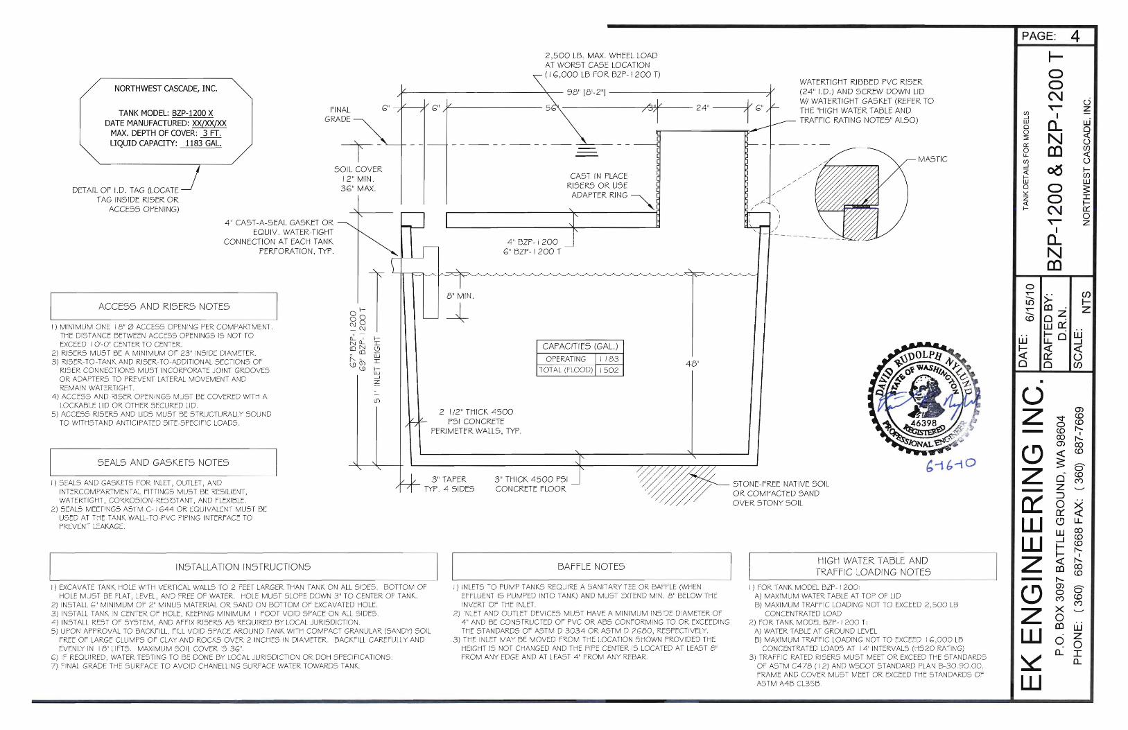
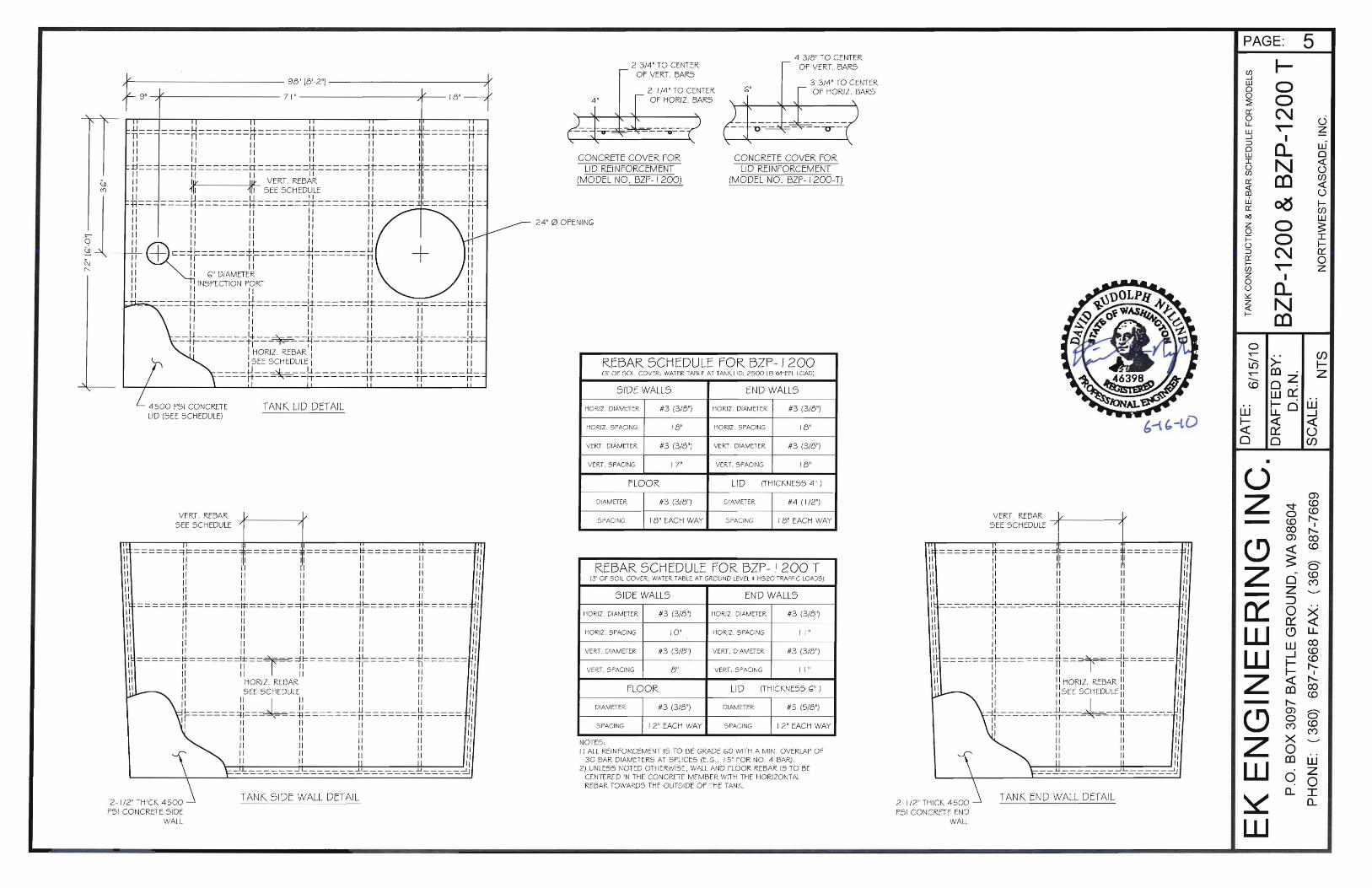
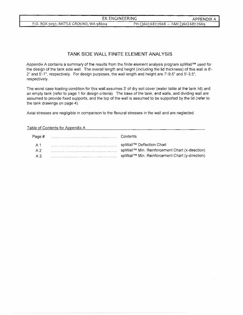
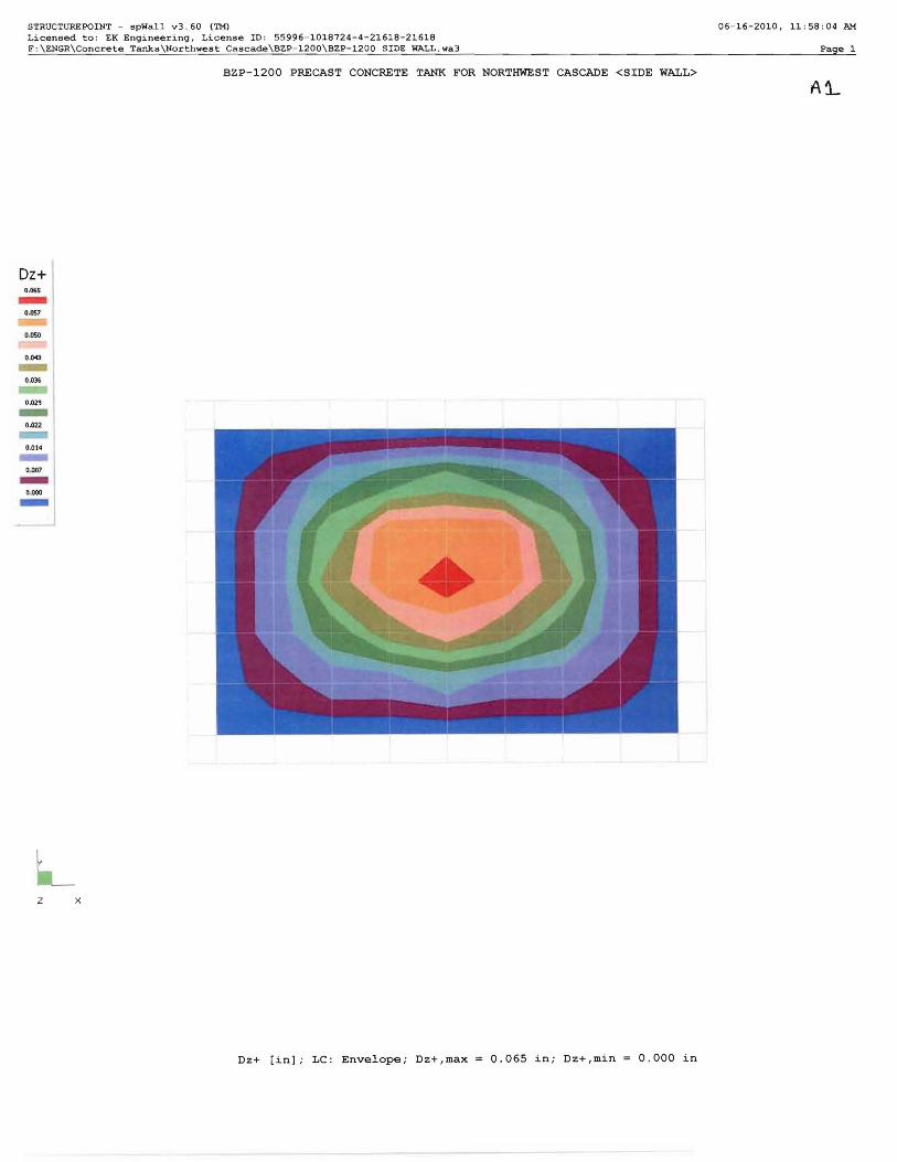
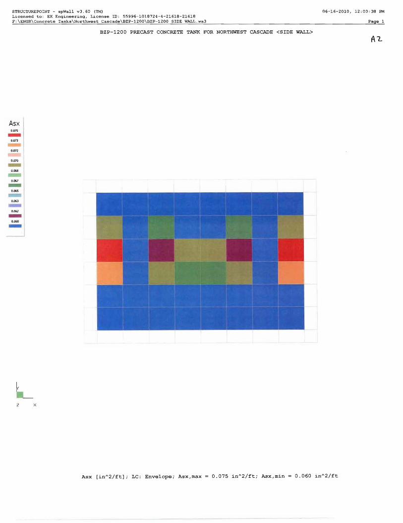
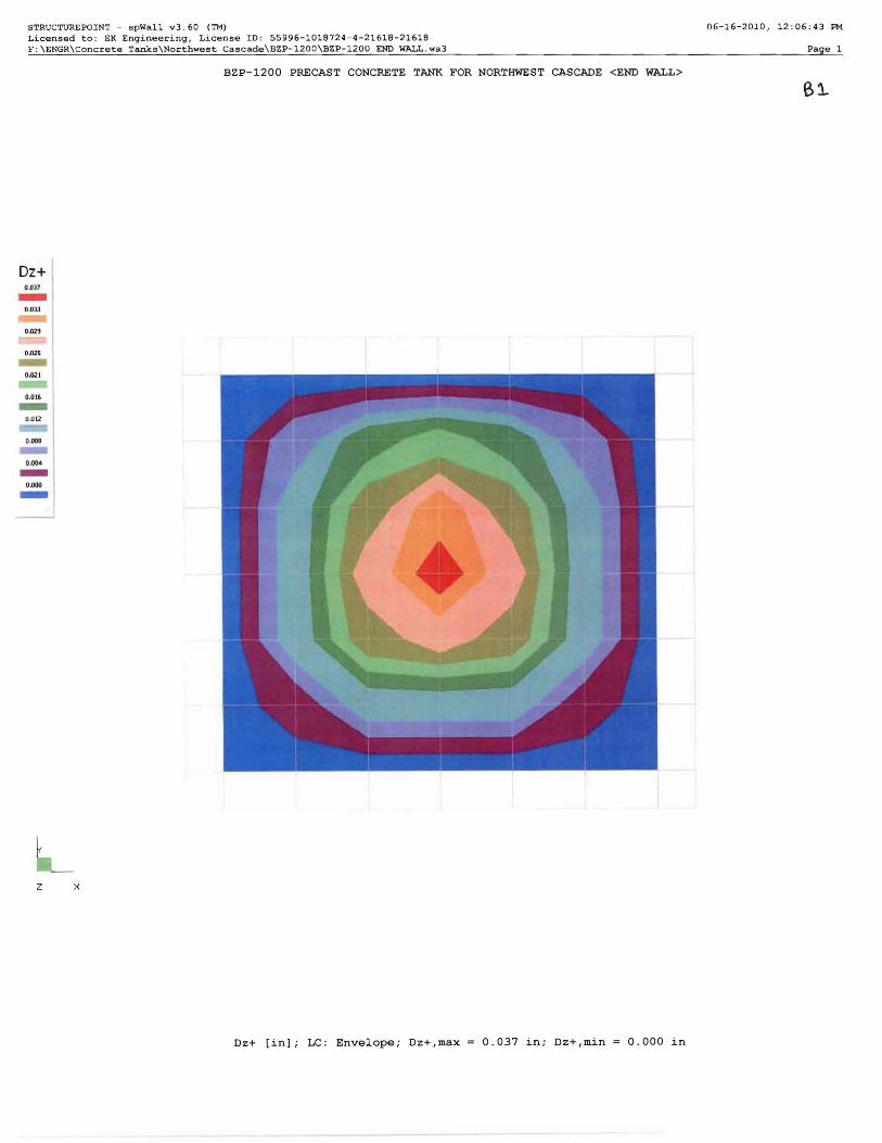
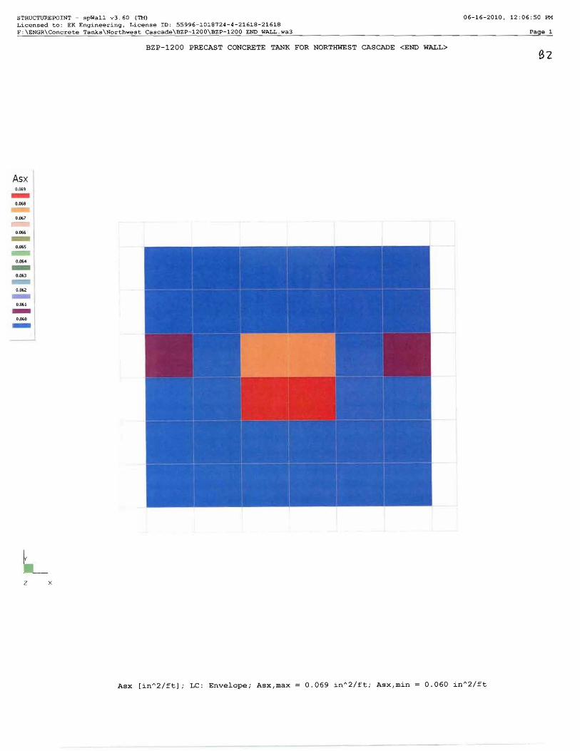