Embed Size (px)
Citation preview
RE-DECKING, STRENGTHENING
AND WIDENING OF A 380M LONG TWIN
TRUSS BRIDGE IN, TORONTO,
ONTARIO, CANADA
BIOGRAPHY
Edward Li, P.Eng., is a Vice President and Senior Structural Engineer with Morrison Hershfield Limited, a multi-disciplinary consulting engineering company with offices located across Canada and the United States. Edward is a graduate of the University of Hong Kong and specialises in planning, design and construction support for new bridge and bridge rehabilitation projects in the Province of Ontario, and has authored many publications and papers on bridge engineering. Edward was the Structural Project Manager of this subject bridge project.
Chak Lo, P.Eng., is a Senior Structural Engineer and Technical Director for Transportation Structures Department of Morrison Hershfield responsible for the technical development and quality control of the department. Chak graduated from the University of Toronto in 1973. Chak was involved in numerous challenging bridge and structural projects including the subject structure. Chak is also a member of the Institution of Civil Engineers (U.K.), Canadian Society for Civil Engineers and the China Civil Engineering Society.
SUMMARY
This project involved the $60M (all figures in Canadian dollars) re-decking and widening of a 380m long, 10 span, high-level steel truss structure located on the busiest highway in Toronto, Canada, carrying over 400,000 vehicles per day over a deep ravine (Hogg’s Hollow) some 40m below the deck. This paper will describe the planning, design and construction of this challenging bridge project, and innovative ideas developed to address the issues, including the need to maintain all 12 lanes on this section of the highway during peak traffic hours throughout the construction period.
Over 1,200 tonnes of new structural steel were fabricated and installed on this structure, plus the full area temporary steel access platform erected below the deck, making this one of the largest structural steel engineering projects completed in Ontario in recent years.
The project was completed in 2012 and over one year ahead of schedule, and was selected to receive the 2013 Ontario Region Steel Design Award of Merit in the Engineering Category presented by the Canadian Institute of Steel Construction (CISC).
EDWARD KA-YU LI
CHAK Y LO
1 of 10
RE-DECKING, STRENGTHENING AND WIDENING OF A 380M LONG TWIN TRUSS BRIDGE IN, TORONTO,
ONTARIO, CANADA
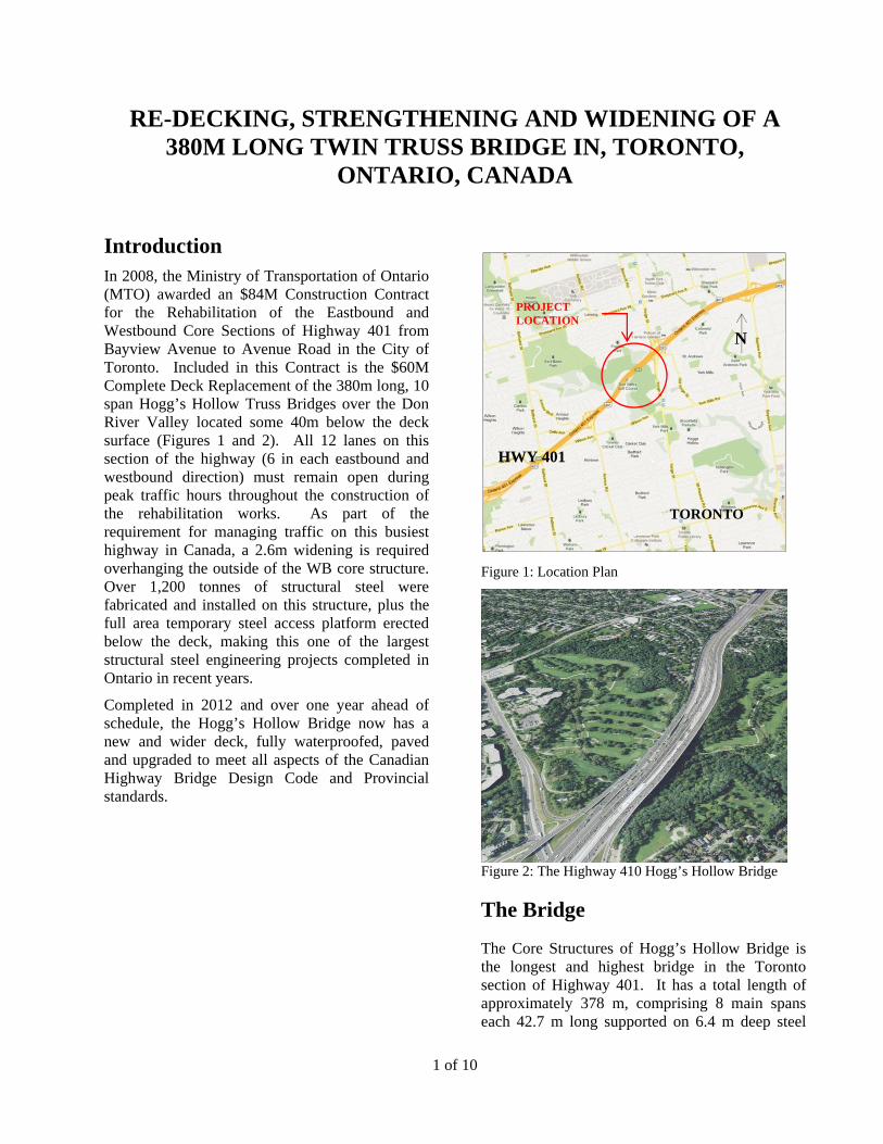
Introduction In 2008, the Ministry of Transportation of Ontario (MTO) awarded an $84M Construction Contract for the Rehabilitation of the Eastbound and Westbound Core Sections of Highway 401 from Bayview Avenue to Avenue Road in the City of Toronto. Included in this Contract is the $60M Complete Deck Replacement of the 380m long, 10 span Hogg’s Hollow Truss Bridges over the Don River Valley located some 40m below the deck surface (Figures 1 and 2). All 12 lanes on this section of the highway (6 in each eastbound and westbound direction) must remain open during peak traffic hours throughout the construction of the rehabilitation works. As part of the requirement for managing traffic on this busiest highway in Canada, a 2.6m widening is required overhanging the outside of the WB core structure. Over 1,200 tonnes of structural steel were fabricated and installed on this structure, plus the full area temporary steel access platform erected below the deck, making this one of the largest structural steel engineering projects completed in Ontario in recent years.
Completed in 2012 and over one year ahead of schedule, the Hogg’s Hollow Bridge now has a new and wider deck, fully waterproofed, paved and upgraded to meet all aspects of the Canadian Highway Bridge Design Code and Provincial standards.
Figure 1: Location Plan
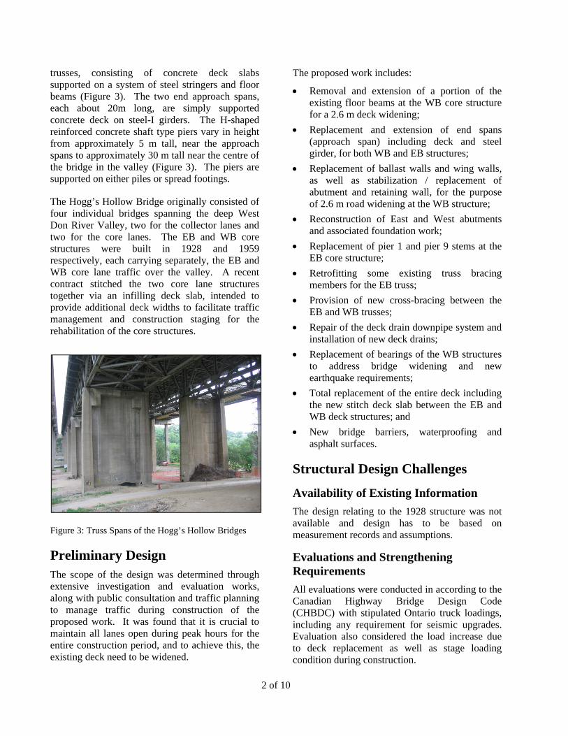
Figure 2: The Highway 410 Hogg’s Hollow Bridge
The Bridge
The Core Structures of Hogg’s Hollow Bridge is the longest and highest bridge in the Toronto section of Highway 401. It has a total length of approximately 378 m, comprising 8 main spans each 42.7 m long supported on 6.4 m deep steel
PROJECT LOCATION
TORONTO
HWY 401
N
2 of 10
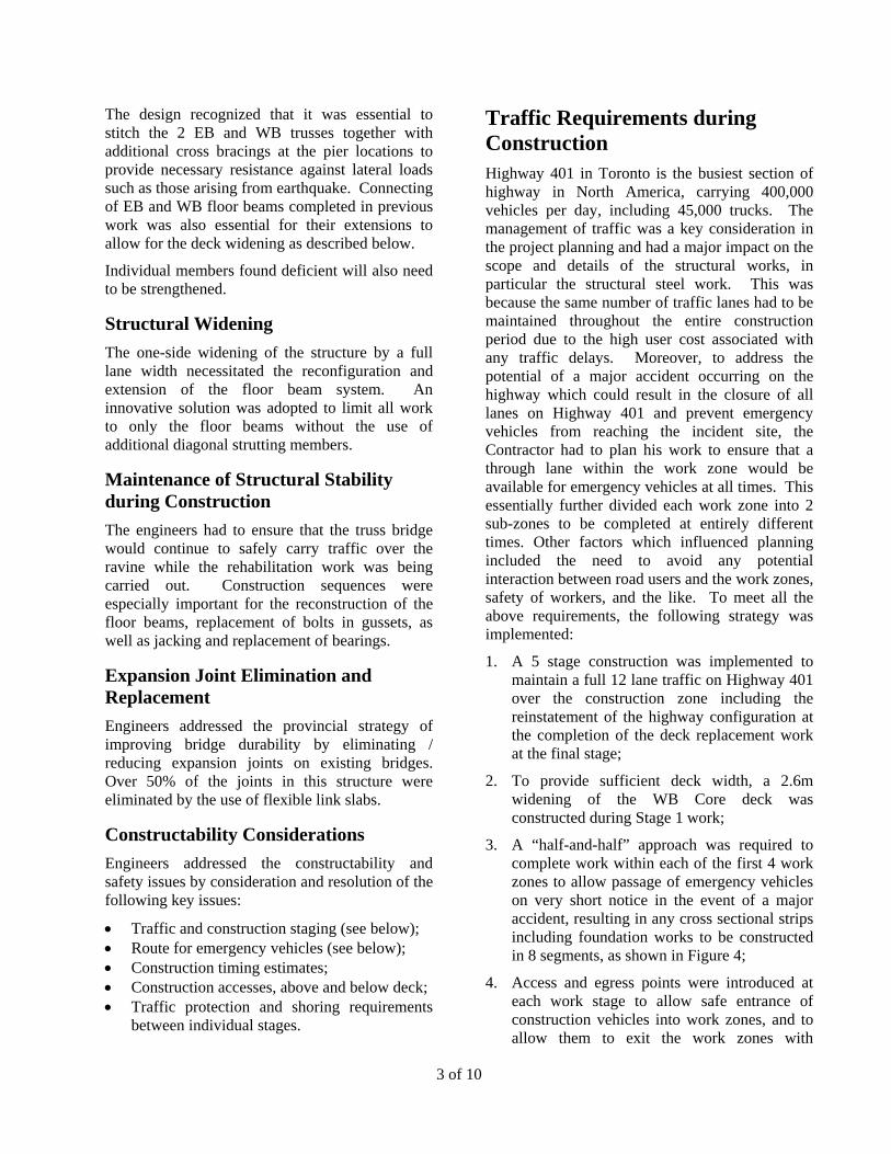
trusses, consisting of concrete deck slabs supported on a system of steel stringers and floor beams (Figure 3). The two end approach spans, each about 20m long, are simply supported concrete deck on steel-I girders. The H-shaped reinforced concrete shaft type piers vary in height from approximately 5 m tall, near the approach spans to approximately 30 m tall near the centre of the bridge in the valley (Figure 3). The piers are supported on either piles or spread footings.
The Hogg’s Hollow Bridge originally consisted of four individual bridges spanning the deep West Don River Valley, two for the collector lanes and two for the core lanes. The EB and WB core structures were built in 1928 and 1959 respectively, each carrying separately, the EB and WB core lane traffic over the valley. A recent contract stitched the two core lane structures together via an infilling deck slab, intended to provide additional deck widths to facilitate traffic management and construction staging for the rehabilitation of the core structures.
Figure 3: Truss Spans of the Hogg’s Hollow Bridges
Preliminary Design The scope of the design was determined through extensive investigation and evaluation works, along with public consultation and traffic planning to manage traffic during construction of the proposed work. It was found that it is crucial to maintain all lanes open during peak hours for the entire construction period, and to achieve this, the existing deck need to be widened.
The proposed work includes:
Removal and extension of a portion of the existing floor beams at the WB core structure for a 2.6 m deck widening;
Replacement and extension of end spans (approach span) including deck and steel girder, for both WB and EB structures;
Replacement of ballast walls and wing walls, as well as stabilization / replacement of abutment and retaining wall, for the purpose of 2.6 m road widening at the WB structure;
Reconstruction of East and West abutments and associated foundation work;
Replacement of pier 1 and pier 9 stems at the EB core structure;
Retrofitting some existing truss bracing members for the EB truss;
Provision of new cross-bracing between the EB and WB trusses;
Repair of the deck drain downpipe system and installation of new deck drains;
Replacement of bearings of the WB structures to address bridge widening and new earthquake requirements;
Total replacement of the entire deck including the new stitch deck slab between the EB and WB deck structures; and
New bridge barriers, waterproofing and asphalt surfaces.
Structural Design Challenges
Availability of Existing Information
The design relating to the 1928 structure was not available and design has to be based on measurement records and assumptions.
Evaluations and Strengthening Requirements
All evaluations were conducted in according to the Canadian Highway Bridge Design Code (CHBDC) with stipulated Ontario truck loadings, including any requirement for seismic upgrades. Evaluation also considered the load increase due to deck replacement as well as stage loading condition during construction.
3 of 10
The design recognized that it was essential to stitch the 2 EB and WB trusses together with additional cross bracings at the pier locations to provide necessary resistance against lateral loads such as those arising from earthquake. Connecting of EB and WB floor beams completed in previous work was also essential for their extensions to allow for the deck widening as described below.
Individual members found deficient will also need to be strengthened.
Structural Widening
The one-side widening of the structure by a full lane width necessitated the reconfiguration and extension of the floor beam system. An innovative solution was adopted to limit all work to only the floor beams without the use of additional diagonal strutting members.
Maintenance of Structural Stability during Construction
The engineers had to ensure that the truss bridge would continue to safely carry traffic over the ravine while the rehabilitation work was being carried out. Construction sequences were especially important for the reconstruction of the floor beams, replacement of bolts in gussets, as well as jacking and replacement of bearings.
Expansion Joint Elimination and Replacement
Engineers addressed the provincial strategy of improving bridge durability by eliminating / reducing expansion joints on existing bridges. Over 50% of the joints in this structure were eliminated by the use of flexible link slabs.
Constructability Considerations
Engineers addressed the constructability and safety issues by consideration and resolution of the following key issues:
Traffic and construction staging (see below); Route for emergency vehicles (see below); Construction timing estimates; Construction accesses, above and below deck; Traffic protection and shoring requirements
between individual stages.
Traffic Requirements during Construction Highway 401 in Toronto is the busiest section of highway in North America, carrying 400,000 vehicles per day, including 45,000 trucks. The management of traffic was a key consideration in the project planning and had a major impact on the scope and details of the structural works, in particular the structural steel work. This was because the same number of traffic lanes had to be maintained throughout the entire construction period due to the high user cost associated with any traffic delays. Moreover, to address the potential of a major accident occurring on the highway which could result in the closure of all lanes on Highway 401 and prevent emergency vehicles from reaching the incident site, the Contractor had to plan his work to ensure that a through lane within the work zone would be available for emergency vehicles at all times. This essentially further divided each work zone into 2 sub-zones to be completed at entirely different times. Other factors which influenced planning included the need to avoid any potential interaction between road users and the work zones, safety of workers, and the like. To meet all the above requirements, the following strategy was implemented:
1. A 5 stage construction was implemented to maintain a full 12 lane traffic on Highway 401 over the construction zone including the reinstatement of the highway configuration at the completion of the deck replacement work at the final stage;
2. To provide sufficient deck width, a 2.6m widening of the WB Core deck was constructed during Stage 1 work;
3. A “half-and-half” approach was required to complete work within each of the first 4 work zones to allow passage of emergency vehicles on very short notice in the event of a major accident, resulting in any cross sectional strips including foundation works to be constructed in 8 segments, as shown in Figure 4;
4. Access and egress points were introduced at each work stage to allow safe entrance of construction vehicles into work zones, and to allow them to exit the work zones with
4 of 10
sufficient acceleration lengths to safely merge with mainline traffic; and
5. All temporary traffic provisions, lanes and tapers, etc. were designed to accommodate 100km/hr. traffic at all times.
Figure 4: Sub-staging within 1 of the 4 working stages
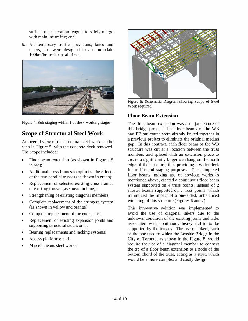
Scope of Structural Steel Work An overall view of the structural steel work can be seen in Figure 5, with the concrete deck removed. The scope included:
Floor beam extension (as shown in Figures 5 in red);
Additional cross frames to optimize the effects of the two parallel trusses (as shown in green);
Replacement of selected existing cross frames of existing trusses (as shown in blue);
Strengthening of existing diagonal members;
Complete replacement of the stringers system (as shown in yellow and orange);
Complete replacement of the end spans;
Replacement of existing expansion joints and supporting structural steelworks;
Bearing replacements and jacking systems;
Access platforms; and
Miscellaneous steel works
Figure 5: Schematic Diagram showing Scope of Steel Work required
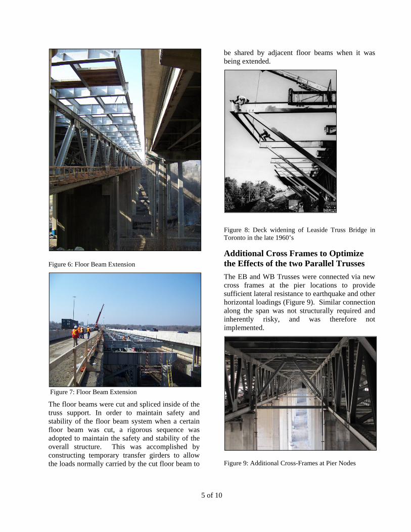
Floor Beam Extension
The floor beam extension was a major feature of this bridge project. The floor beams of the WB and EB structures were already linked together in a previous project to eliminate the original median gap. In this contract, each floor beam of the WB structure was cut at a location between the truss members and spliced with an extension piece to create a significantly larger overhang on the north edge of the structure, thus providing a wider deck for traffic and staging purposes. The completed floor beams, making use of previous works as mentioned above, created a continuous floor beam system supported on 4 truss points, instead of 2 shorter beams supported on 2 truss points, which minimized the impact of a one-sided, unbalanced widening of this structure (Figures 6 and 7).
This innovative solution was implemented to avoid the use of diagonal rakers due to the unknown condition of the existing joints and risks associated with continuous heavy traffic to be supported by the trusses. The use of rakers, such as the one used to widen the Leaside Bridge in the City of Toronto, as shown in the Figure 8, would require the use of a diagonal member to connect the tip of a floor beam extension to a node of the bottom chord of the truss, acting as a strut, which would be a more complex and costly design.
5 of 10
Figure 6: Floor Beam Extension
Figure 7: Floor Beam Extension
The floor beams were cut and spliced inside of the truss support. In order to maintain safety and stability of the floor beam system when a certain floor beam was cut, a rigorous sequence was adopted to maintain the safety and stability of the overall structure. This was accomplished by constructing temporary transfer girders to allow the loads normally carried by the cut floor beam to
be shared by adjacent floor beams when it was being extended.
Figure 8: Deck widening of Leaside Truss Bridge in Toronto in the late 1960’s
Additional Cross Frames to Optimize the Effects of the two Parallel Trusses
The EB and WB Trusses were connected via new cross frames at the pier locations to provide sufficient lateral resistance to earthquake and other horizontal loadings (Figure 9). Similar connection along the span was not structurally required and inherently risky, and was therefore not implemented.
Figure 9: Additional Cross-Frames at Pier Nodes
6 of 10
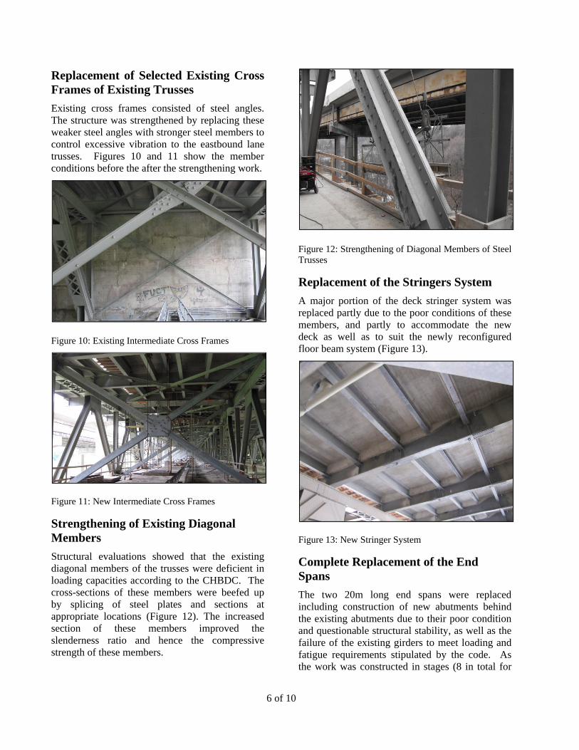
Replacement of Selected Existing Cross Frames of Existing Trusses
Existing cross frames consisted of steel angles. The structure was strengthened by replacing these weaker steel angles with stronger steel members to control excessive vibration to the eastbound lane trusses. Figures 10 and 11 show the member conditions before the after the strengthening work.
Figure 10: Existing Intermediate Cross Frames
Figure 11: New Intermediate Cross Frames
Strengthening of Existing Diagonal Members
Structural evaluations showed that the existing diagonal members of the trusses were deficient in loading capacities according to the CHBDC. The cross-sections of these members were beefed up by splicing of steel plates and sections at appropriate locations (Figure 12). The increased section of these members improved the slenderness ratio and hence the compressive strength of these members.
Figure 12: Strengthening of Diagonal Members of Steel Trusses
Replacement of the Stringers System
A major portion of the deck stringer system was replaced partly due to the poor conditions of these members, and partly to accommodate the new deck as well as to suit the newly reconfigured floor beam system (Figure 13).
Figure 13: New Stringer System
Complete Replacement of the End Spans
The two 20m long end spans were replaced including construction of new abutments behind the existing abutments due to their poor condition and questionable structural stability, as well as the failure of the existing girders to meet loading and fatigue requirements stipulated by the code. As the work was constructed in stages (8 in total for
7 of 10
each span), a lot of effort and resources were spent in splices, laps, as well as shoring of the highway for the deep excavation required to build the substructures. See Figure 14.
Figure 14: End (Approach) Spans to be constructed in 8 laterally-connected segments
Replacement of Existing Expansion Joints and Supporting Structural Steelworks
5 of the 11 existing expansion joints were replaced, while the remainder joints were eliminated by accommodating some of the thermal movements in the flexibility of the supporting steel members and the deck made continuous over these supports. Nevertheless as the new expansion joint hardware components were only supported at intermittent points of the stringer system, they were not only just anchorages for the joints, but were also structural steel members by themselves and were designed and detailed accordingly, including deflection control of these members under moving traffic loading.
Figure 15 below shows the reinforcing details of a link slab with the expansion joint removed.
Figure 15: Elimination of Existing Expansion Joints using Flexible Link Slabs
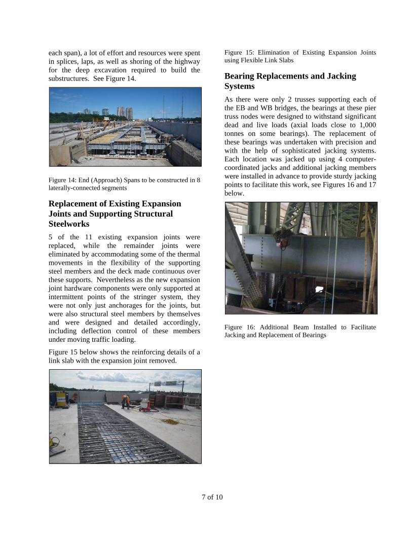
Bearing Replacements and Jacking Systems
As there were only 2 trusses supporting each of the EB and WB bridges, the bearings at these pier truss nodes were designed to withstand significant dead and live loads (axial loads close to 1,000 tonnes on some bearings). The replacement of these bearings was undertaken with precision and with the help of sophisticated jacking systems. Each location was jacked up using 4 computer-coordinated jacks and additional jacking members were installed in advance to provide sturdy jacking points to facilitate this work, see Figures 16 and 17 below.
Figure 16: Additional Beam Installed to Facilitate Jacking and Replacement of Bearings
8 of 10
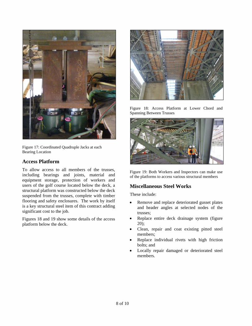
Figure 17: Coordinated Quadruple Jacks at each Bearing Location
Access Platform
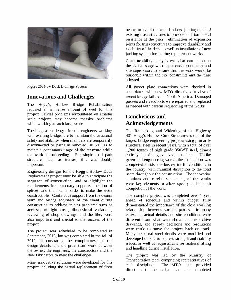
To allow access to all members of the trusses, including bearings and joints, material and equipment storage, protection of workers and users of the golf course located below the deck, a structural platform was constructed below the deck suspended from the trusses, complete with timber flooring and safety enclosures. The work by itself is a key structural steel item of this contract adding significant cost to the job.
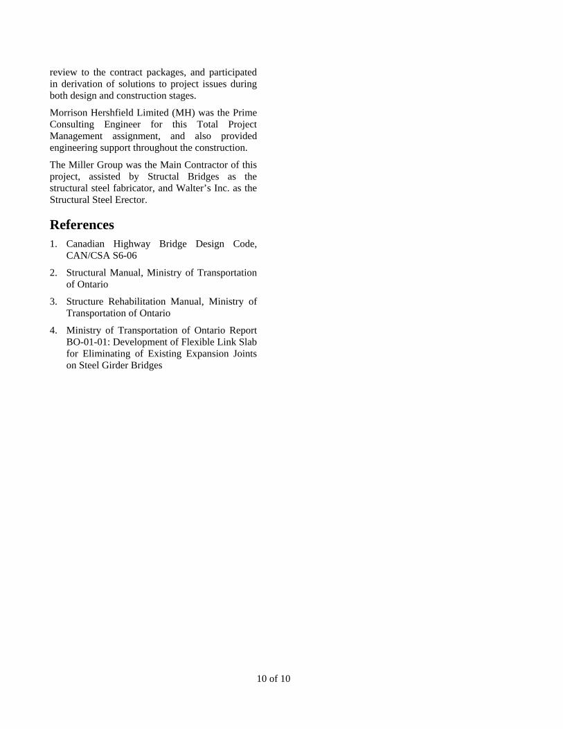
Figures 18 and 19 show some details of the access platform below the deck.
Figure 18: Access Platform at Lower Chord and Spanning Between Trusses
Figure 19: Both Workers and Inspectors can make use of the platforms to access various structural members
Miscellaneous Steel Works
These include:
Remove and replace deteriorated gusset plates and header angles at selected nodes of the trusses;
Replace entire deck drainage system (figure 20);
Clean, repair and coat existing pitted steel members;
Replace individual rivets with high friction bolts; and
Locally repair damaged or deteriorated steel members.
9 of 10
Figure 20: New Deck Drainage System
Innovations and Challenges The Hogg’s Hollow Bridge Rehabilitation required an immense amount of steel for this project. Trivial problems encountered on smaller scale projects may become massive problems while working at such large scale.
The biggest challenges for the engineers working with existing bridges are to maintain the structural safety and stability when members are temporarily disconnected or partially removed, as well as to maintain continuous usage of the structure while the work is proceeding. For single load path structures such as trusses, this was doubly important.
Engineering designs for the Hogg’s Hollow Deck Replacement project must be able to anticipate the sequence of construction, and to highlight the requirements for temporary supports, location of splices, and the like, in order to make the work constructible. Continuous support from the design team and bridge engineers of the client during construction to address in-situ problems such as accesses to tight areas, dimensional variations, reviewing of shop drawings, and the like, were also important and crucial to the success of the project.
The project was scheduled to be completed in September, 2013, but was completed in the fall of 2012, demonstrating the completeness of the design details, and the great team work between the owner, the engineers, the constructors and the steel fabricators to meet the challenges.
Many innovative solutions were developed for this project including the partial replacement of floor
beams to avoid the use of rakers, joining of the 2 existing truss structures to provide addition lateral resistance at the piers , elimination of expansion joints for truss structures to improve durability and ridability of the deck, as well as installation of new jacking system for bearing replacement works.
Constructability analysis was also carried out at the design stage with experienced contractor and site supervisors to ensure that the work would be buildable within the site constraints and the time allowed.
All gusset plate connections were checked in accordance with new MTO directives in view of recent bridge failures in North America. Damaged gussets and rivets/bolts were repaired and replaced as needed with careful sequencing of the works.
Conclusions and Acknowledgements The Re-decking and Widening of the Highway 401 Hogg’s Hollow Core Structures is one of the largest bridge engineering projects using primarily structural steel in recent years, with a total of over 1,200 tonnes of high grade 350WT steel, almost entirely hot-dip galvanized, installed. Unlike greenfield engineering works, the installation was completed amidst the busiest traffic conditions in the country, with minimal disruption to the road users throughout the construction. The innovative solutions and careful sequencing of the works were key elements to allow speedy and smooth completion of the work.
The complex project was completed over 1 year ahead of schedule and within budget, fully demonstrated the importance of the close working relationship between various parties. In many cases, the actual details and site conditions were different from what were shown on the archive drawings, and speedy decisions and resolutions were made to move the project back on track. Many structural steel details were modified and developed on site to address strength and stability issues, as well as requirements for material lifting and handling during installation.
The project was led by the Ministry of Transportation team comprising representatives of each discipline. The MTO team provided directions to the design team and completed
10 of 10
review to the contract packages, and participated in derivation of solutions to project issues during both design and construction stages.
Morrison Hershfield Limited (MH) was the Prime Consulting Engineer for this Total Project Management assignment, and also provided engineering support throughout the construction.
The Miller Group was the Main Contractor of this project, assisted by Structal Bridges as the structural steel fabricator, and Walter’s Inc. as the Structural Steel Erector.
References 1. Canadian Highway Bridge Design Code,
CAN/CSA S6-06
2. Structural Manual, Ministry of Transportation of Ontario
3. Structure Rehabilitation Manual, Ministry of Transportation of Ontario
4. Ministry of Transportation of Ontario Report BO-01-01: Development of Flexible Link Slab for Eliminating of Existing Expansion Joints on Steel Girder Bridges