Embed Size (px)
Citation preview

Linear Motion andAssembly Technologies ServicePneumaticsHydraulics
Electric Drives and Controls
Variable Plug-In Motor A6VE
RE 91 606/10.07 1/16Replaces: 06.05
Features– Variable plug-in motor with axial tapered piston rotary group
of bent axis design for hydrostatic drives in open and closed circuits
– Easy assembly, simply «plugs-in» into mechanical gearboxes (no installation tolerances to consider)
– The design of the motor with the mounting flange in the cen-ter of the housing allows it to be almost fully integrated into a mechanical gearbox to give an extremely compact unit
– For use in mobile applications
– Installation ready and tested unit
– The displacement is infinitely variable from Vg max to Vg min = 0
– The output speed is dependent on the flow of the pump and the displacement of the motor
– The torque increases with the pressure differential between the high and low pressure side and with increasing displace-ment
– Further information:
Variable motor A6VM__________________________RE 91604
Series 6Size Nominal pressure / Peak pressure28 to 160 400 / 450 bar250 350 / 400 barOpen and closed circuits
Technical data sheet
ContentsOrdering Code / Standard Program 2
Technical Data 4
Unit Dimensions, Port Plate 02 6
Unit Dimensions, Port Plate 22 with Integral Counterbalance Valve 8
Circuit Diagram for Port Plate 22 9
Flush and Boost Pressure Valve 10
Speed Measurement 11
Connectors for Solenoids (only for EP, EZ, DA) 12
Installation Notes 13
Project Sheet 14
General Notes 16
�/16 Bosch Rexroth AG A6VE RE 91 606/10.07
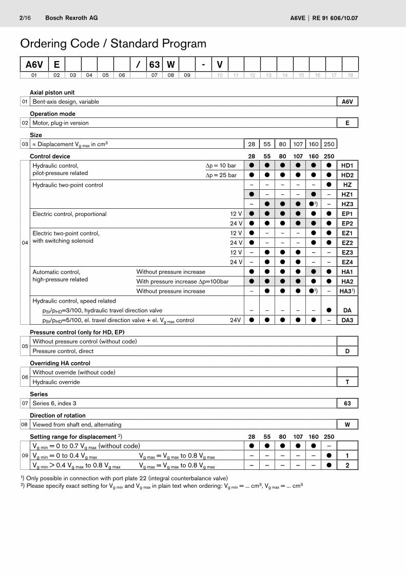
Ordering Code / Standard Program
Axial piston unit01 Bent-axis design, variable A6V
Operation mode02 Motor, plug-in version E
Size03 ≈ Displacement Vg max in cm3 28 55 80 107 160 250
Control device �8 55 80 107 160 �50
04
Hydraulic control, pilot-pressure related
Δp = 10 bar HD1
Δp = 25 bar HD�
Hydraulic two-point control – – – – – HZ
– – – – HZ1
– 1) – HZ3
Electric control, proportional 12 V EP1
24 V EP�
Electric two-point control, with switching solenoid
12 V – – – EZ1
24 V – – – EZ�
12 V – – – EZ3
24 V – – – EZ4
Automatic control, high-pressure related
Without pressure increase HA1
With pressure increase Δp=100bar HA�
Without pressure increase – 1) – HA31)
Hydraulic control, speed related
pSt/pHD=3/100, hydraulic travel direction valve – – – – – DA
pSt/pHD=5/100, el. travel direction valve + el. Vg max control 24V – DA3
Pressure control (only for HD, EP)
05Without pressure control (without code)
Pressure control, direct D
Overriding HA control
06Without override (without code)
Hydraulic override T
Series07 Series 6, index 3 63
Direction of rotation08 Viewed from shaft end, alternating W
Setting range for displacement 2) �8 55 80 107 160 �50
09
Vg min = 0 to 0.7 Vg max (without code) —Vg min = 0 to 0.4 Vg max Vg max = Vg max to 0.8 Vg max — — — — — 1Vg min > 0.4 Vg max to 0.8 Vg max Vg max = Vg max to 0.8 Vg max — — — — — �
1) Only possible in connection with port plate 22 (integral counterbalance valve)2) Please specify exact setting for Vg min and Vg max in plain text when ordering: Vg min = ... cm3, Vg max = ... cm3
A6V E / 63 W - V01 02 03 04 05 06 07 08 09 10 11 12 13 14 15 16 17 18

Bosch Rexroth AGRE 91 606/10.07 A6VE 3/16
Seals �8 55 80 107 160 �5010 FKM (fluor-caoutchouc) V
Shaft end
11Splined shaft DIN 5480 – – – A
– – – Z
Mounting flange �8 55 80 107 160 �50
12
2-hole, similar to ISO 3019-2 – L
4-hole, similar to ISO 3019-2 – – – – – M
2-hole (modified adaption flange) – – – – – U
Service line ports 3)
13
SAE flange portsA/B side, opposite
0� 0 0�0
7 0�7
Port plate with integral counterbalance valve (with brake release valve) and secondary valve; SAE flange ports A/B bottom 6)
�� 1 – – ��14)
2 – – ���4)
Valves
14
Without valve 0
Brake release valve (pilot pressure for brake release)
Internal boring 1
External piping �
With flush and boost pressure valve 7
Speed measurement �8 55 80 107 160 �50
15Without speed measurement (without code)
Prepared for speed measurement (HDD) 5) – – F
Connector for solenoids (only sizes 28 to 160) EP1/� EZ1/� EZ3/4 DA.16 DEUTSCH - molded connector, 2-pin – without suppressor diode ❍ P
Start of control
17
Port plate 02 At Vg min (standard for HA) A
At Vg max (standard for HD, HZ, EP, EZ, DA) B
Port plate 22 At Vg min (standard for HA3) – – B
At Vg max (standard for HZ3) – – B
Standard / special version
18
Standard version (without code)
With attachment part -K
Special version -S
With attachment part -SK
3) Metric fixing threads4) Only possible in combination with HZ3, HA3 control5) Complete order recommended, speed sensor page 116) Use project sheet for project planning of the integral counterbalance valve
= available = on request – = not available = preferred program
Ordering Code / Standard Program
A6V E / 63 W - V01 02 03 04 05 06 07 08 09 10 11 12 13 14 15 16 17 18

4/16 Bosch Rexroth AG A6VE RE 91 606/10.07
Hydraulic fluidBefore starting project planning, please refer to our data sheets RE 90220 (mineral oil), RE 90221 (environmentally ac-ceptable hydraulic fluids) and RE 90223 (HF hydraulic fluids) for detailed information regarding the choice of hydraulic fluid and application conditions.
The A6VE variable plug-in motor is unsuitable for operation with HFA. If HFB, HFC and HFD or environmentally accept-able hydraulic fluids are being used, the limitations regarding technical data and seals mentioned in RE 90221 and RE 90223 must be observed.
When ordering, please indicate the used hydraulic fluid.
Operating viscosity range
For optimum efficiency and service life, select an operating vis-cosity (at operating temperature) within the optimum range of
nopt = optimum operating viscosity 16 to 36 mm2/s
depending on the circuit temperature (closed circuit) and tank temperature (open circuit).
Limits of viscosity range
The limiting values for viscosity are as follows:
Sizes 28 to 160:
nmin = 5 mm2/s short-term (t < 3 min) at max. perm. temperature of tmax = +115°C.
nmax = 1600mm2/s, short-term (t < 3 min) at cold start (p ≤ 30 bar, n ≤ 1000 rpm, tmin = -40°C). Only for starting up without load. Optimum operating
viscosity must be reached within approx. 15 minutes.
Size 250:
nmin = 10 mm2/s, short-term (t < 3 min) at max. perm. temperature of tmax = +90°C.
nmax = 1000 mm2/s, short-term (t < 3 min) at cold start (p ≤ 30 bar, n ≤ 1000 rpm, tmin = -25°C). Only for starting up without load. Optimum operating
viscosity must be reached within approx. 15 minutes.
Note that the maximum hydraulic fluid temperature of 115°C (90°C at size 250) must not be exceeded locally either (e.g. in the bearing area). The temperature in the bearing area is - depending on pressure and speed - up to 12 K higher than the average case drain temperature.
Special measures are necessary in the temperature range from -40°C to -25°C (cold start phase); please contact us.
For detailed information about use at low temperatures, see RE 90300-03-B.
Technical DataFiltrationThe finer the filtration, the higher the cleanliness level of the hydraulic fluid and the longer the service life of the axial piston unit.
To ensure functional reliability of the axial piston unit, the hy-draulic fluid must have a cleanliness level of at least 20/18/15 according to ISO 4406.
At very high hydraulic fluid temperatures (90°C to max. 115°C), at least cleanliness level of 19/17/14 according to ISO 4406 is required.
If the above classes cannot be observed, please contact us.
Operating pressure rangeMaximum pressure on port A or B (pressure data in accordance with to DIN 24312)
for sizes 28 to 160
Nominal pressure pN ____________________________ 400 barPeak pressure pmax __________________________________________ 450 barTotal pressure (pressure A + pressure B) pmax ______ 700 bar
for size 250
Nominal pressure pN ____________________________ 350 barPeak pressure pmax _____________________________ 400 barTotal pressure (pressure A + pressure B) pmax ______ 700 bar
Please note:These values are valid for loading which is free of radial forces. With additional radial loading, see RE 91604.
Direction of flow
Direction of rotation, viewed on shaft end
clockwise counter-clockwise
A to B B to A
Speed rangeNo limit to minimum speed nmin. If uniformity of motion is re-quired, speed nmin must not be less than 50 rpm. See table of values on page 5 for maximum speed.

1
2
3
4
5
6
2000 4000 6000 8000 10000
Bosch Rexroth AGRE 91 606/10.07 A6VE 5/16
Technical DataShaft seal ring
Permissible pressure load
The service life of the shaft seal ring is affected by the speed of the motor and the case drain pressure. It is recommended that the average, continuous case drain pressure at operating temperature 3 bar absolute not be exceeded (max. permissible case drain pressure 6 bar absolute at reduced speed, see dia-gram). Short-term (t < 0.1 s) pressures spikes of up to 10 bar absolute are permitted. The service life of the shaft seal ring de-creases with an increase in the frequency of pressures spikes.
The case pressure must be equal to or greater than the external pressure on the shaft seal ring.
Temperature range
The FKM shaft seal ring is permissible for case temperatures of -25°C to +115°C.
Note:For application cases below -25°C, an NBR shaft seal ring is necessary (permissible temperature range: -40°C to +90°C). Please state NBR shaft seal ring in plain text when ordering. Please contact us.
Effect of case pressure on start of controlAn increase in the case pressure has an effect on the following controls when control of the variable motor begins:
HA1T (sizes 28 to 160) _________________________ increaseHD, EP, HA, HA.T (size 250) _____________________ increaseDA __________________________________________ decrease
The start of control is set in the factory at a case pressure of pabs = 2 bar (sizes 28 to 160) and pabs = 1 bar (size 250).
Perm
. pre
ssur
e p a
bs. m
ax.
in b
ar
Size 107
Size 250
Speed n in rpm
Size 28
Size 55Size 80
Size 160
Table of values (theoretical values, without efficiency and tolerances; values rounded)
Size Size �8 55 80 107 160 �50
Displacement 1) Vg max cm3 28.1 54.8 80 107 160 250Vg 0 cm3 0 0 0 0 0 0
Speed max. (while adhering to max. permissible flow)
nmax at Vg max rpm 5550 4450 3900 3550 3100 2700nmax1 at Vg < Vg1 rpm 8750 7000 6150 5600 4900 3600Vg1 = 0.63 x Vg max cm3 18 35 51 68 101 188 2)nmax 0 at Vg 0 rpm 10450 8350 7350 6300 5500 3600
Max flow qV max L/min 156 244 312 380 496 675Max torque Tmax at Vg max 3) Nm 179 349 509 681 1019 1391Rotary stiffness Vg max to Vg/2 cmin Nm/rad 5670 10400 15500 21000 35300 59500
Vg/2 to 0(interpolated) cmax Nm/rad 18100 32000 47900 65200 105000 181000Moment of inertia for rotary group JTW kgm2 0.0014 0.0042 0.008 0.0127 0.0253 0.061Angular acceleration maximum a rad/s2 47000 31500 24000 19000 11000 10000Filling capacity V L 0.5 0.75 1.2 1.5 2.4 3.0Mass (approx.) Port plate 02 m kg 16 26 34 47 64 90
Port plate 22 m kg – 35 43 53 72 –1) The minimum and maximum displacements are infinitely variable, see ordering codes on page 2.
(default settings for sizes 250 unless specified in order: Vg min = 0.2 • Vg max, Vg max = Vg max).2) Vg1 = 0.75 x Vg max (approx.)3) Sizes 28 to 160: Δp = 400 bar; size 250: Δp = 350 bar
Caution: Exceeding the permissible limit values may result in a loss of function, a reduction in service life or in the destruction of the axial piston unit. Other permissible limit values with respect to speed variation, reduced angular acceleration as a function of the fre-quency and the permissible startup angular acceleration (lower than the maximum angular acceleration) can be found in data sheet RE 90261.
For further information see technical data sheet RE 91604 (variable motor A6VM):– Selection diagram and details regarding the choice of hydraulic fluid– Permissible displacement and inlet pressure in relation to speed– Permissible radial and axial loading on drive shaft– Description and dimensions of the control units

T2
T1
2 1T (T )
T2T1Y
1M
G X
Y
1M
B A
X G
A9
ø340
30°
M16
30°
270
105.5105.5 ø22
ø300
A16
A29
øA6 A7
A2
A8
A28
A4
øA18
øA19
øA20
øA17
1230
'
A1
A3
A10A11
A27
A12A13
A15
A21
A22
A25A24
øA23
A26
A14
6/16 Bosch Rexroth AG A6VE RE 91 606/10.07
For unit dimensions of control units, see technical data sheet of variable motor A6VM (RE 91604)
Sizes 28 to 160
Size Service line port A, B SAE J518
Case drain port T1; T� 1)
DIN 385�
�8 3/4 in M18x1.5; 12 deep 140 Nm 2)
55 3/4 in M18x1.5; 12 deep 140 Nm 2)
80 1 in M18x1.5; 12 deep 140 Nm 2)
107 1 in M18x1.5; 12 deep 140 Nm 2)
160 1 1/4 in M26x1.5; 16 deep 230 Nm 2)
�50 1 1/4 in M22x1.5; 14 deep 210 Nm 2)1) 1x plugged 2) Please observe the general notes for the max. tightening torques on page 16
For other ports, see variable motor A6VM (RE 91604)!
Ports
Before finalizing your design, please request a binding installation drawing. Dimensions in mmUnit Dimensions
Groove for O-ring
(to drive shaft collar)
HD1, HD� Hydraulic control, pilot-pressure relatedSAE flange ports A/B side, opposite (0�)
Size 250Detail
Differential dimension mounting flange A6VM to A6VE

W3
W2
W5
W6
øW4
W1
Bosch Rexroth AGRE 91 606/10.07 A6VE 7/16
Standard flange L (sizes 28 to 160), M (size 250)
Size A1 A� A3 A4 øA6 A7 A8 A9 (DIN 13) 1) A10 A11 A1� A13 A14 A15
�8 91 20 47 10 ø19 50.8 23.8 M10x1.5; 17 deep 88 54 — 15 14 R10
55 123 24 77 14 ø19 50.8 23.8 M10x1.5; 17 deep 91 50 22 15 16 R6
80 130 28 78 16 ø25 57.2 27.8 M12x1.75; 17 deep 109.5 65 30 15 18 R10
107 137 30 84 18 ø25 57.2 27.8 M12x1.75; 17 deep 121.8 72 35 15 18 R12
160 171 34 109 20 ø32 66.7 31.8 M14x2; 19 deep 122 67 29 15 20 R5
�50 204 44 103 20 ø32 66.7 31.8 M14x2; 19 deep 131.5 – – 14 25 –
Size A16 A17 A18 A19 A�0 A�1 A�� øA�3 A�4 A�5 A�6 A�7 A�8 A�9 O-ring �)
�8 89 135-0.025 110 – 86 188 160 ø13.5 62.5 62.5 142 64 35.5 132 126x4
55 92 160-0.025 139 132 104 235 200 ø17 72.5 72.5 166 59 35.5 152 150x4
80 110.5 190-0.029 151 143 116 260 224 ø21 78.5 78.5 198 79 35.5 164 182x4
107 122.8 200-0.029 168 160 132 286 250 ø21 86.5 86.5 210 82 40.5 180 192x4
160 123 200-0.029 188 180 146 286 250 ø21 98.5 98.5 210 83 40.5 204 192x4
�50 133.5 260-0.081 – 230 – – – – – – – 83.5 48.5 224 250x5
Adaption flange U (size 107)
Size A1 A� A3 A4 A5 A6 A7 A8 A9 (DIN 13) 1) A10 A11 A1� A13 A14
107 150 30 96 18 15.5 25 57.2 27.8 M12x1.75; 17 deep 109.5 59.7 22.7 18 15
Size A15 A16 A17 A18 A19 A�0 A�1 A�� A�3 A�4 A�5 A�6 A�7 A�8 A�9 O-ring �)
107 R8 110.5 190-0.025 168 160 132 260 224 22 86.5 86.5 198 91.5 13.8 70 182x41) Please observe the general notes for the max. tightening torques on page 162) The O-ring is not included in supply
Shaft endsSplined shaft DIN 5480
Size Shaft end W1 W� W3 øW4 W5 W6
�8 A (W30x2x30x14x9g) M10 7.5 22 ø35 8 35
55 Z (W30x2x30x14x9g) M12 9.5 28 ø45 8 35
80 A (W40x2x30x18x9g) M16 12 36 ø50 8 45
107 Z (W40x2x30x18x9g) M12 9.5 28 ø60 8 45
160 A (W50x2x30x24x9g) M16 12 36 ø70 11 55
�50 Z (W50x2x30x24x9g) M16 12 36 ø60 9 58
Before finalizing your design, please request a binding installation drawing. Dimensions in mmUnit Dimensions

B15
B18
B19
B17
B13øB14
B16
B2B1
B7B8
B4
B20
B5
B6
B9B10
B3
B12B11
Y
XBre
MAMB
S
Y
Z
T2(T1)
Bre(X)
S
Z
A
B
T1
Bri
T2
8/16 Bosch Rexroth AG A6VE RE 91 606/10.07
HA3 Automatic control, high-pressure related without pressure increasePort plate 22 with integral counterbalance valve
X Pilot pressure port (open for HZ3 and HA3T, closed for HA3) DIN 3852 M14x1.5; 12 deep
MA, MB Gauge port DIN 3852 M14x1.5; 12 deep
Bre External brake release port (open for design 22�) DIN 3852 M14x1.5; 12 deep
Bri Internal brake release port (not present on design with flange U) ø4
Note: Port plates HZ3 and HA3 are not identical!
Size B18 B19 B�0 Service line port A, BSAE J518
Case drain port T1; T� 1)
DIN 385�Boosting SDIN 385�
55 74 51 10� 3/4in M18x1.5; 12 deep 140 Nm 2) M22x1.5; 14 deep 210 Nm 2)
80 90 53 114 1in M18x1.5; 12 deep 140 Nm 2) M22x1.5; 14 deep 210 Nm 2)
107 96 58 1�� 1in M18x1.5; 12 deep 140 Nm 2) M22x1.5; 14 deep 210 Nm 2)
160 94 65 136 1 1/4in M26x1.5; 16 deep 230 Nm 2) M27x2; 16 deep 330 Nm 2)1) 1x plugged 2) Please observe the general notes for the max. tightening torques on page 16
Size B1 B� B3 B4 B5 B6 B7 B8 B9 B10 B11 B1� B13 B14 B15 (DIN 13) 2) B16 B17
55 192 144 127 144 117 37 133 91 83 85 64 259 50.8 19 M10x1.5; 17 deep 23.8 80
80 198 150 136 162 132 40 138 93 83 90 69 259 57.2 25 M12x1.75; 17 deep 27.8 86
107 202 161 139 171.5 143 40 144 99 85 96 72 259 57.2 25 M12x1.75; 17 deep 27.8 86
160 240 195 152 197 162 47 177 128 102 108 78 259 66.7 32 M14x2; 19 deep 31.8 94
Before finalizing your design, please request a binding installation drawing. Dimensions in mmUnit Dimensions
Detail Detail
Ports

MB
Vg min
Vg max
B
A
Bre
XM1 MBT1
Bri
T2 S MA
Vg max
Vg min
A
X
Bre
MBT1
Bri
T2 S MA
Bosch Rexroth AGRE 91 606/10.07 A6VE 9/16
For port plate �� with integral counterbalance valve
A6VE...HA3...��1 (Brake release via internal boring) A6VE...HZ3...��� (Brake release via external piping)
(Port X open for HA3T)
Before finalizing your design, please request a binding installation drawing. Dimensions in mmCircuit Diagram

A1 A4
A3
A2
273 318
10/16 Bosch Rexroth AG A6VE RE 91 606/10.07
The flush and boost pressure valve is used to remove heat from the closed circuit and to ensure that a minimum boost pressure is present (opening pressure 16 bar, fixed; note when setting primary valve). A side effect is the flushing of the case.
Warm hydraulic fluid is directed from the respective low pres-sure side into the motor case. This is then fed into the tank, together with the case drain fluid. The hydraulic fluid drawn out of the closed circuit in this way must be replaced by cooled hydraulic fluid that is supplied by the boost pump.
In an open circuit, the flush and boost pressure valve is used solely to flush the case from the return line.
The valve is fitted on the variable motor or integrated into the control unit (depending on the type of control and the size).
Orifices can be used to adjust the flushing volumes as re-quired.
Standard flushing volume at low pressure ΔpLP = 25 bar
Size Flushing volume
Mat. no. of orifice
28, 55 3.5 L/min R909651766
80 5 L/min R909419695
107 8 L/min R909419696
160 10 L/min R909419697
250 10 L/min R909419697
For sizes 28 to 160, orifices for flushing volumes of 3.5 to 10 L/min can be supplied. In the case of non-standard flushing volumes, please specify the desired flushing volume when ordering. The flushing volumes without orifice is approx. 12 to 14 L at low pressure ΔpLP = 25 bar.
Sizes �8 to 160
Size A1 A� A3 A4
�8 152 125 161 —
55 182 133 176 176
80 192 141 194 176
107 203 144 200 187
160 245 154 220 —
Size �50
Flush and Boost Pressure Valve
Size �50
Unit dimensionsSizes �8 to 160
Orifice
Orifice
HA1 HA�
HD, HZ1EP, EZ1EZ�, DA
HA3HZ3EZ3EZ4
HD, HZ, EP, EZ, DA HA
Before finalizing your design, please request a binding installation drawing. Dimensions in mm

U D
G
T2
M1
Vg min
Vg max
A
A
A-A 30°
FE
CB
A30°
D
ø18.
2
2220 20
22
90°
Bosch Rexroth AGRE 91 606/10.07 A6VE 11/16
Version "F" (sizes 55 to 160) prepared for speed measurementThe A6VE...F ("prepared for speed measurement", i.e. without sensor) versions have teeth on the rotary group. The rotat-ing, toothed rotary group generates a signal in proportion to the speed. The signal is picked up by a sensor and can be forwarded for evaluation.
Version F is suitable for mounting to the HDD Hall-effect speed sensor (see RE 95135). The HDD sensor is flanged with two fixing screws at the specified port. In the standard version, the port is plugged with a pressure-resistant flange cover.
We recommend ordering the A6VE variable motor with mounted sensor. Please specify the ordering code for the sen-sor separately.
Circuit diagram
Size 55 80 107 160
Number of teeth 54 58 67 75
A 25.8 16.8 14.7 28.3
B 72.2 75.4 83.1 90.4
C 110.3 113.5 121.2 128.5
D 32 32 32 32
E 83.4±0.1 87.1±0.1 95.9±0.1 104.4±0.1
F 121.7 124.4 133.2 141.7
Suitable speed sensor: sizes 55 to 160: HDD.L32../20 (see RE 95 135)
Speed Measurement
Without HDD sensor With HDD sensor
View X
Unit dimensions
M6x1 (DIN 13) 8 deep
Before finalizing your design, please request a binding installation drawing. Dimensions in mm

1�/16 Bosch Rexroth AG A6VE RE 91 606/10.07
DEUTSCH DT04-�P-EP04, �-pinMolded, without bi-directional suppressor diode
(for EP, EZ, DA)______________________________________P
Type of protection according to DIN/EN 60529: IP67 and IP69K
Mating connector
DEUTSCH DT06-2S-EP04
Rexroth Mat. No. R902601804
consisting of: DT designation
– 1 case ______________________________ DT06-2S-EP04
– 1 wedge ____________________________ W2S
– 2 female connectors ___________________ 0462-201-16141
The mating connector is not included in supply.
This can be supplied by Rexroth on request.
36
68,5
ø37
1 )
50
(2)(1)
1) Solenoid with dia. 45 for following controls: EZ3, EZ4
Note for round solenoids:
The position of the connector can be changed by turning the solenoid body.
Proceed as follows: 1. Loosen the fixing nut (1)2. Turn the solenoid body (2) to the desired position3. Tighten the fixing nut Tightening torque of the fixing nut: 5+1 Nm
(width across flats SW26, 12-sided DIN 3124)
We reserve the right to change the position of the solenoid connector from that depicted in the brochure or drawing during assembly of the solenoid.
Connectors for Solenoids
Bosch Rexroth AGRE 91 606/10.07 A6VE 13/16
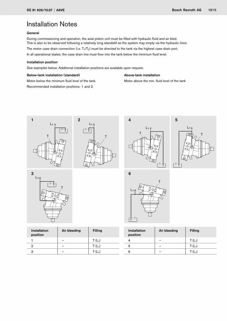
General
During commissioning and operation, the axial piston unit must be filled with hydraulic fluid and air bled. This is also to be observed following a relatively long standstill as the system may empty via the hydraulic lines.
The motor case drain connection (i.e. T1/T2) must be directed to the tank via the highest case drain port.
In all operational states, the case drain line must flow into the tank below the minimum fluid level.
Installation position
See examples below. Additional installation positions are available upon request.
Below-tank installation (standard)
Motor below the minimum fluid level of the tank.
Recommended installation positions: 1 and 2.
Above-tank installation
Motor above the min. fluid level of the tank
1 � 4 5
3 6
Installation position
Air bleeding Filling Installation position
Air bleeding Filling
1 – T (L1) 4 – T (L1)
2 – T (L1) 5 – T (L1)
3 – T (L1) 6 – T (L1)
Installation Notes
T
T T
L1
L1
L1L1
L1
L1
T
T T

14/16 Bosch Rexroth AG A6VE RE 91 606/10.07
Project Sheet for variable motor A6VE with integral counterbalance valve (sizes 55 to 160)
Please return the completed project sheet when ordering the motor.
Responsible: ______________________________________ Copy: ___________________________________________
Company: ______________________________________
Place: ______________________________________
Name: ______________________________________
Department: ______________________________________
Fax: ______________________________________
Phone: ______________________________________
Customer: ______________________________________ Annual need: __________________________________________
Machine: ______________________________________
Total weight: ______________________________________t
Track drive: Crawler excavator Crane other
Diesel engine speed: nmin= _______rpm nmax= _________rpm
Power: P = ________kW
Hydraulic fluid: Mineral oil (HL, HLP) acc. to DIN 51 524 Phosphate ester (HFD-R)
Others: ______________________________________
Hydraulic components
1. Drive pump(s)
Manufacturer: ____________________________________
�. Directional control valve
Manufacturer: ____________________________________ Model: ________________________________
Symbol of drive spool (center position): ___________________

Bosch Rexroth AGRE 91 606/10.07 A6VE 15/16
3. Hydraulic motor
Type code acc. to RE 91606 ___________________________________________________________________________________
Flow/motor qV max = ___________l/min
Displacement/motor Vg min = ___________cm3/rev Vg max = _________ cm3/rev
Necessary min. boost pressure (self-suction limit at nmax) pmin = ___________bar
Secondary pressure valves: pressure setting pmax = ___________bar
Park brake: no yes release pressure range from______ bar to ____bar
Brake release internal (Bri) external (Bre) separate by pilot pressure
4. Track drive gearbox
Manufacturer/Model ___________________________________________________________________________________________
Gear ratio i = ___________________ Sprocket diameter d = _______________ m
Additional information ___________________________________________________________________________________________
Type-code of the motor
acc. to RE 91606
Rexroth material no. (defined after receipt of order): __________________________________
A6VE /63W-V 22
Project Sheet for variable motor A6VE with integral counterbalance valve

16/16 Bosch Rexroth AG A6VE RE 91 606/10.07
© This document, as well as the data, specifications and other information set forth in it, are the exclusive property of Bosch Rexroth AG. It may not be repro-duced or given to third parties without its consent.
The data specified above only serve to describe the product. No statements concerning a certain condition or suitability for a certain application can be de-rived from our information. The information given does not release the user from the obligation of own judgment and verification. It must be remembered that our products are subject to a natural process of wear and aging.
Subject to change.
Bosch Rexroth AG HydraulicsProduct Unit Axial Piston UnitsElchingen Plant Glockeraustraße 2 89275 Elchingen, Germany Phone +49 (0) 73 08 82-0 Fax +49 (0) 73 08 72 [email protected] www.boschrexroth.com/axial-piston-motors
Horb Plant An den Kelterwiesen 14 72160 Horb, Germany Phone +49 (0) 74 51 92-0 Fax +49 (0) 74 51 82 21
General Notes– The A6VE motor is designed to be used in open and closed circuits.
– Project planning, assembly, and commissioning of the motor require the involvement of qualified personnel.
– The service line ports and function ports are only designed for mounting hydraulic lines.
– During and shortly after operation, there is a risk of burns on the motor and especially on the solenoids. Take suitable safety precautions, e.g. wear protective clothing
– There may be shifts in the characteristic depending on the operational state of the motor (operating pressure, fluid temperature).
– Tightening torques: - The tightening torques specified in this data sheet are maximum values and must not be exceeded
(maximum values for screw thread). Manufacturer's instruction for the max. permissible tightening torques of the used armatures must be observed!
- For DIN 13 fixing screws, we recommend checking the tightening torque individually according to VDI 2230 Edition 2003.
– The data and information contained herein must be adhered to.