Embed Size (px)
Citation preview

RDXL120Communication Function
omega.com e-mail: [email protected]
For latest product manuals:omegamanual.info
Shop online at
User’s Guide

Servicing North America:U.S.A.: One Omega Drive, P.O. Box 4047ISO 9001 Certified Stamford, CT 06907-0047
TEL: (203) 359-1660 FAX: (203) 359-7700e-mail: [email protected]
Canada: 976 BergarLaval (Quebec) H7L 5A1, CanadaTEL: (514) 856-6928 FAX: (514) 856-6886e-mail: [email protected]
For immediate technical or application assistance:
U.S.A. and Canada: Sales Service: 1-800-826-6342 / 1-800-TC-OMEGA®
Customer Service: 1-800-622-2378 / 1-800-622-BEST®
Engineering Service: 1-800-872-9436 / 1-800-USA-WHEN®
Mexico: En Espanol: (001) 203-359-7803 e-mail: [email protected]: (001) 203-359-7807 [email protected]
Servicing Europe:Benelux: Postbus 8034, 1180 LA Amstelveen, The Netherlands
TEL: +31 (0)20 3472121 FAX: +31 (0)20 6434643Toll Free in Benelux: 0800 0993344e-mail: [email protected]
Czech Republic: Frystatska 184, 733 01 Karviná, Czech RepublicTEL: +420 (0)59 6311899 FAX: +420 (0)59 6311114Toll Free: 0800-1-66342 e-mail: [email protected]
France: 11, rue Jacques Cartier, 78280 Guyancourt, FranceTEL: +33 (0)1 61 37 2900 FAX: +33 (0)1 30 57 5427Toll Free in France: 0800 466 342e-mail: [email protected]
Germany/Austria: Daimlerstrasse 26, D-75392 Deckenpfronn, GermanyTEL: +49 (0)7056 9398-0 FAX: +49 (0)7056 9398-29Toll Free in Germany: 0800 639 7678e-mail: [email protected]
United Kingdom: One Omega Drive, River Bend Technology CentreISO 9002 Certified Northbank, Irlam, Manchester
M44 5BD United Kingdom TEL: +44 (0)161 777 6611 FAX: +44 (0)161 777 6622Toll Free in United Kingdom: 0800-488-488e-mail: [email protected]
OMEGAnet® Online Service Internet e-mailomega.com [email protected]
It is the policy of OMEGA Engineering, Inc. to comply with all worldwide safety and EMC/EMIregulations that apply. OMEGA is constantly pursuing certification of its products to the European NewApproach Directives. OMEGA will add the CE mark to every appropriate device upon certification.The information contained in this document is believed to be correct, but OMEGA accepts no liability for anyerrors it contains, and reserves the right to alter specifications without notice.WARNING: These products are not designed for use in, and should not be used for, human applications.
1
IntroductionThank you for purchasing our RDXL120 Portable Data Station.This Communication Function Manual provides information necessary for using communication functions and creating communication programs. To ensure correct use, please read this manual thoroughly before beginning operation.In addition to this manual, the User’s Manual (contained in the CD-ROM as with this manual) and Quick Setup Manual are available separately.The User’s Manual provides detailed information regarding all of the functions and operations of the RDXL120 excluding the communication functions. The Quick Setup Manual briefly explains the basic operations such as measurement operation and setup. Use them together with this manual.After reading this manual, keep it in an easily accessible place for later reference. This manual will come in handy when you are unsure of how to operate the product.
Notes• The contents of this manual are subject to change without prior notice.• Figures and illustrations representing display views in this manual may differ from
actual views.• Every effort has been made to ensure accuracy in the preparation of this manual.
However, should any doubts arise or errors come to your attention, please contact the vendor from whom you purchased the product.
• The contents of this manual may not be transcribed or reproduced, in part or in their entirety, without prior permission.
Trademark AcknowledgementsThe company and product names referred to in this document are either trademarks or registered trademarks of their respective holders.
Revision InformationFirst Edition: February, 2009
All Rights Reserved, Copyright ©2009
2
Safety Precautions
When operating the instrument, be sure to observe the cautionary notes given below to ensure correct and safe use of the instrument. If you use the instrument in any way other than as instructed in this manual, the instrument’s protective measures may be impaired.Omega Engineering, Inc. Corporation is by no means liable for any damage resulting from use of the instrument in contradiction to these cautionary notes.The following safety symbols are used on the instrument and in this manual.
Danger! Handle with Care. This symbol indicates that the operator must refer to an explanation in the User’s Manual or this manual in order to avoid risk of injury or death of personnel or damage to the instrument.
This symbol indicates DC voltage/current.
This symbol indicates AC voltage/current.
This symbol indicates ON (power).
This symbol indicates OFF (power).
WARNINGIndicates a hazard that may result in the loss of life or serious injury of the user unless the described instruction is abided by.
CAUTIONIndicates a hazard that may result in an injury to the user and/or physical damage to the product or other equipment unless the described instruction is abided by.
Note Indicates information that should be noted in order to familiarize yourself with the instru-
ment’s operating procedures and/or functions or gives supplementary information.
3
Description of Displays and Exemption from ResponsibilityDescription of Displays
• Some of the representations of product displays shown in this manual may be exaggerated, simplified, or partially omitted for reasons of convenience when explaining them.
• Figures and illustrations representing the controller’s displays may differ from the actual displays in regard to the positions and/or indicated characters (upper-case or lower-case, for example), to the extent that they do not impair correct understanding of the functions and the proper operation and monitoring of the system.
Exemption from Responsibility• Omega Engineering, Inc. does not make any warranties regarding the product except
those mentioned in the WARRANTY that is provided separately.• Omega Engineering, Inc. assumes no liability to any party for any loss or damage,
direct or indirect, caused by the use of the product, or any unpredictable defect of the product.
• Be sure to use spare parts approved by Omega Engineering, Inc. when replacing parts or consumables.
• Modification of the product is strictly prohibited.• Reverse engineering such as the disassembly or decompilation of software is strictly
prohibited.• No portion of the product supplied by Omega Engineering, Inc. may be transferred,
exchanged, leased or sublet for use by any third party without the prior permission of Omega Engineering, Inc.
4
Contents
Safety Precautions ...........................................................................................................................2 Description of Displays and Exemption from Responsibility ............................................................3
Chapter 1 Overview of the Communication Functions 1.1 Relationship between the Communication Function and the Ethernet and
Serial Interfaces ............................................................................................................... 1-1 1.2 Explanation of Functions .................................................................................................. 1-3
Chapter 2 Ethernet Interface 2.1 Ethernet Interface Specifications ...................................................................................... 2-1 2.2 Connecting of the Ethernet Interface ................................................................................ 2-2 2.3 Configuring of the Ethernet Interface ............................................................................... 2-3 2.4 Checking the Connection Status of the Ethernet Interface .............................................. 2-7 2.5 Setting the FTP Client (Setting the Auto Transfer of Measurement and Alarm
Data Files) ........................................................................................................................ 2-8 2.6 FTP Test ..........................................................................................................................2-11 2.7 Setting the Login of Ethernet Communications .............................................................. 2-13 2.8 Showing the Error, Communication, and FTP Log Displays........................................... 2-16 2.9 Setting the Web Server Function.................................................................................... 2-19 2.10 Showing and Using the Monitor or Operator Page ......................................................... 2-22 2.11 Setting the E-mail Transmission Function ...................................................................... 2-24 2.12 E-mail Transmission Test................................................................................................ 2-29 2.13 Starting/Stopping E-mail Transmissions ......................................................................... 2-31
Chapter 3 Serial Interface 3.1 RS-232 Interface Specifications and Setup Procedure .................................................... 3-1 3.2 RS-485 Interface Specifications and Setup Procedure .................................................... 3-5 3.3 USB Communication Specifications and Setup Procedure .............................................. 3-8
Chapter 4 Modbus Protocol 4.1 Modbus Protocol Specifications and Function Codes ...................................................... 4-1 4.2 Register Assignments (for Modbus Slave) ....................................................................... 4-2 4.3 Modbus Error Response (for Modbus Slave) ................................................................... 4-3 4.4 Setting the Modbus Master Function ................................................................................ 4-4 4.5 Data Dropout Handling of the Modbus Master ................................................................. 4-7
Chapter 5 Standard Protocol 5.1 Command Syntax ............................................................................................................. 5-1 5.2 Response Syntax ............................................................................................................. 5-3 5.3 A List of Commands ....................................................................................................... 5-19 5.4 Input Range Parameters ................................................................................................ 5-23
5.5 Setting Commands (Setting) .......................................................................................... 5-255.6 Setting Commands (Control) .......................................................................................... 5-315.7 Basic Setting Commands ............................................................................................... 5-335.8 Output Commands (Control) .......................................................................................... 5-435.9 Output Commands (Setting/Measurement/Data Output) ............................................... 5-455.10 Output Commands (RS-485 Dedicated Commands) ..................................................... 5-475.11 Maintenance/Test Commands (Available when using the maintenance/test
server function via Ethernet communications) ............................................................... 5-48
5
1
2
3
4
5
6
7
App
Index
Chapter 6 Status 6.1 Status Information andFilter ............................................................................................. 6-1 6.2 Bit Structure of the Status Information ............................................................................. 6-2
Chapter 7 Error Messages 7.1 Error Messages Related to Settings ................................................................................. 7-1 7.2 Error Messages Related to Operation .............................................................................. 7-3 7.3 Communication Error Messages ...................................................................................... 7-8
Appendix Appendix 1 ASCII Character Codes ..................................................................................App-1 Appendix 2 Login Process .................................................................................................App-2 Appendix 3 Data Output Flow ............................................................................................App-4 Appendix 4 Time Zones and XG Command Parameters ...................................................App-6
Index
Contents
1-1
1.1 Relationship between the Communication Function and the Ethernet and Serial Interfaces
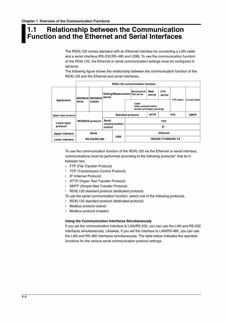
The RDXL120 comes standard with an Ethernet interface for connecting a LAN cable and a serial interface (RS-232/RS-485 and USB). To use the communication function of the RDXL120, the Ethernet or serial communication settings must be configured in advance.The following figure shows the relationship between the communication function of the RDXL120 and the Ethernet and serial interfaces.
Application
10BASE-T/100BASE-TX
IP
Serial communication control
MODBUS slave
FTP server
Maintenance/Test serverSetting/Measurement
server
RDXL120 communication function
MODBUS master
Serial
Lower layer protocol
Upper layer protocol
Upper interface
Lower interface
Web server
FTP client E-mail client
USB
MODBUS protocol
Standard protocol HTTP FTP SMTP
TCP
Ethernet
Login(User authentication/access privileges granting)
RS-232/RS-485
To use the communication function of the RDXL120 via the Ethernet or serial interface, communications must be performed according to the following protocols* that lie in between two.• FTP (File Transfer Protocol)• TCP (Transmission Control Protocol)• IP (Internet Protocol)• HTTP (Hyper Text Transfer Protocol)• SMTP (Simple Mail Transfer Protocol)• RDXL120 standard protocol (dedicated protocol)To use the serial communication function, select one of the following protocols.• RDXL120 standard protocol (dedicated protocol)• Modbus protocol (slave)• Modbus protocol (master)
Using the Communication Interfaces SimultaneouslyIf you set the communication interface to LAN/RS-232, you can use the LAN and RS-232 interfaces simultaneously. Likewise, if you set the interface to LAN/RS-485, you can use the LAN and RS-485 interfaces simultaneously. The table below indicates the operable functions for the various serial communication protocol settings.
Chapter 1 Overview of the Communication Functions
1-2
1
2
3
4
5
6
7
App
Index
Overview
of the C
om
municatio
n Functions
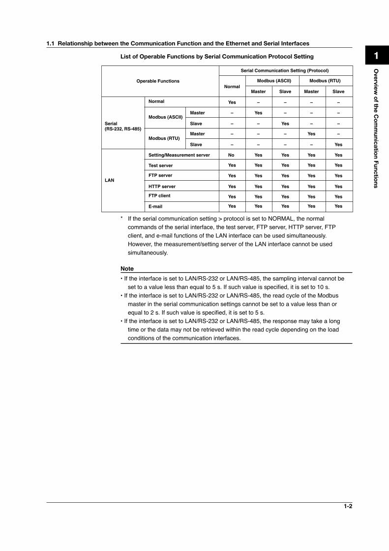
List of Operable Functions by Serial Communication Protocol Setting
Serial Communication Setting (Protocol)
Operable FunctionsNormal
Slave Master SlaveMaster
Serial(RS-232, RS-485)
LAN
Setting/Measurement server No
Yes
Yes
Yes
– –
–
–
–
–
–
–
–
–
–
– –
– – ––
–
–
–
Yes
Yes
Yes
Yes
Yes
Yes
Yes Yes Yes Yes Yes
Yes Yes Yes Yes Yes
Yes Yes Yes Yes Yes
Yes Yes Yes Yes Yes
Yes Yes Yes Yes Yes
Test server
FTP server
HTTP server
FTP client
Normal
Modbus (ASCII)Master
Slave
Master
SlaveModbus (RTU)
Modbus (ASCII) Modbus (RTU)
* If the serial communication setting > protocol is set to NORMAL, the normal commands of the serial interface, the test server, FTP server, HTTP server, FTP client, and e-mail functions of the LAN interface can be used simultaneously. However, the measurement/setting server of the LAN interface cannot be used simultaneously.
Note• If the interface is set to LAN/RS-232 or LAN/RS-485, the sampling interval cannot be
set to a value less than equal to 5 s. If such value is specified, it is set to 10 s.• If the interface is set to LAN/RS-232 or LAN/RS-485, the read cycle of the Modbus
master in the serial communication settings cannot be set to a value less than or equal to 2 s. If such value is specified, it is set to 5 s.
• If the interface is set to LAN/RS-232 or LAN/RS-485, the response may take a long time or the data may not be retrieved within the read cycle depending on the load conditions of the communication interfaces.
1.1 Relationship between the Communication Function and the Ethernet and Serial Interfaces
1-3
1.2 Explanation of Functions
This section gives an overview of the communication function that can be used to control the RDXL120.
Modbus CommunicationModbus Slave• The Modbus protocol can be used to read the measured/calculated data written to the
input register of the RDXL120 from a PC or write/read communication input data from the hold register of the RDXL120.
• For details on the Modbus function codes that the RDXL120 supports, see section 4.1.• This function can be used only when communicating via the serial interface.• For a description on the settings required to use this function, see sections 4.2 and
4.3.
Modbus Master• Loads the measured data and other types of data of other instruments using the
Modbus protocol as communication channel input. The loaded data can be scaled and displayed with a unit that you assign. The data can also be handled on a calculation channel.
• Function for writing data to other instruments is not supported.• For details on the Modbus function codes that the RDXL120 supports, see section
4.1.• This function can be used only when communicating via the serial interface.• For a description on the settings required in using this function, see section 4.4.
Setting/Measurement Server• This function can be used to set almost all of the settings that can be configured using
the front panel keys. This function cannot be used to (1) turn the power switch ON/OFF, (2) set the user name/password for communications, (3) set the user name/password for key login, and (4) set the destination of the FTP client function.
• The following types of data can be output.• Measured/calculated data.• Data in the internal memory or files in the external storage medium.• Setup data.• Log data of operation errors and communications.
• The commands that can be used through this function are setting commands and output commands.
• This function can be used when communicating via the Ethernet or the serial interface.
Maintenance/Test Server• This function can be used to output connection information, network information, and
other information regarding Ethernet communications.• The commands that can be used through this function are maintenance/test
commands.• This function can be used only when communicating via the Ethernet interface.
1-4
1
2
3
4
5
6
7
App
Index
Overview
of the C
om
municatio
n Functions
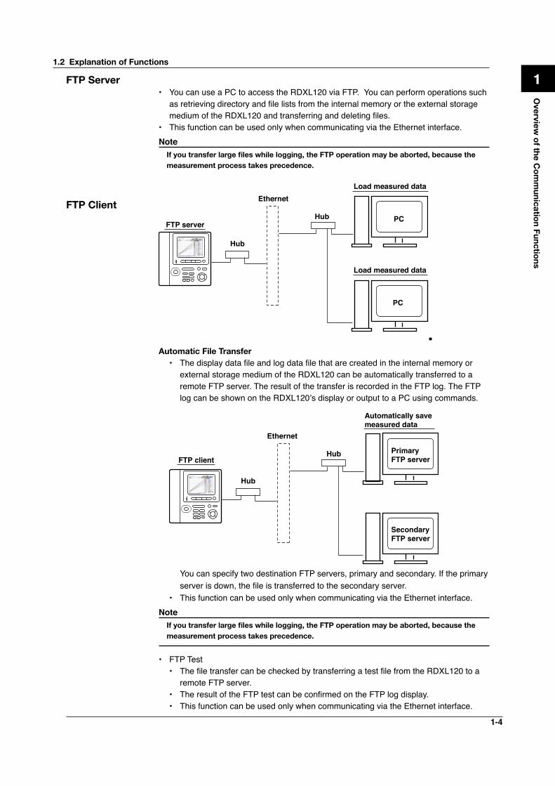
FTP Server• You can use a PC to access the RDXL120 via FTP. You can perform operations such
as retrieving directory and file lists from the internal memory or the external storage medium of the RDXL120 and transferring and deleting files.
• This function can be used only when communicating via the Ethernet interface.Note Ifyoutransferlargefileswhilelogging,theFTPoperationmaybeaborted,becausethe
measurement process takes precedence.
PC
Ethernet
Hub
Hub
Load measured data
PC
Load measured data
FTP server
FTP Client
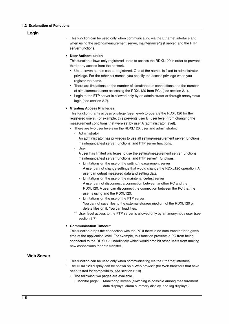
•Automatic File Transfer
• The display data file and log data file that are created in the internal memory or external storage medium of the RDXL120 can be automatically transferred to a remote FTP server. The result of the transfer is recorded in the FTP log. The FTP log can be shown on the RDXL120’s display or output to a PC using commands.
Ethernet
Primary FTP server
Hub
Hub
Automatically save measured data
Secondary FTP server
FTP client
You can specify two destination FTP servers, primary and secondary. If the primary server is down, the file is transferred to the secondary server.
• This function can be used only when communicating via the Ethernet interface.Note Ifyoutransferlargefileswhilelogging,theFTPoperationmaybeaborted,becausethe
measurement process takes precedence.
• FTP Test• The file transfer can be checked by transferring a test file from the RDXL120 to a
remote FTP server.• The result of the FTP test can be confirmed on the FTP log display.• This function can be used only when communicating via the Ethernet interface.
1.2 Explanation of Functions
1-5
Login• This function can be used only when communicating via the Ethernet interface and
when using the setting/measurement server, maintenance/test server, and the FTP server functions.
• User Authentication This function allows only registered users to access the RDXL120 in order to prevent
third party access from the network.• Up to seven names can be registered. One of the names is fixed to administrator
privilege. For the other six names, you specify the access privilege when you register the name.
• There are limitations on the number of simultaneous connections and the number of simultaneous users accessing the RDXL120 from PCs (see section 2.1).
• Login to the FTP server is allowed only by an administrator or through anonymous login (see section 2.7).
• Granting Access Privileges This function grants access privilege (user level) to operate the RDXL120 for the
registered users. For example, this prevents user B (user level) from changing the measurement conditions that were set by user A (administrator level).• There are two user levels on the RDXL120, user and administrator.
• Administrator An administrator has privileges to use all setting/measurement server functions,
maintenance/test server functions, and FTP server functions.• User A user has limited privileges to use the setting/measurement server functions,
maintenance/test server functions, and FTP server*1 functions.• Limitations on the use of the setting/measurement server A user cannot change settings that would change the RDXL120 operation. A
user can output measured data and setting data.• Limitations on the use of the maintenance/test server A user cannot disconnect a connection between another PC and the
RDXL120. A user can disconnect the connection between the PC that the user is using and the RDXL120.
• Limitations on the use of the FTP server You cannot save files to the external storage medium of the RDXL120 or
delete files on it. You can load files.*1 User level access to the FTP server is allowed only by an anonymous user (see
section 2.7).
• Communication Timeout This function drops the connection with the PC if there is no data transfer for a given
time at the application level. For example, this function prevents a PC from being connected to the RDXL120 indefinitely which would prohibit other users from making new connections for data transfer.
Web Server• This function can be used only when communicating via the Ethernet interface.• The RDXL120 display can be shown on a Web browser (for Web browsers that have
been tested for compatibility, see section 2.10).• The following two pages are available.
• Monitor page: Monitoring screen (switching is possible among measurement data displays, alarm summary display, and log displays)
1.2 Explanation of Functions
1-6
1
2
3
4
5
6
7
App
Index
Overview
of the C
om
municatio
n Functions
• Operator page: This page allows you to switch the RDXL120 display. You can also switch to Setting mode or File Operation mode to control the RDXL120 in the respective mode.
You can use access control (user name and password) to limit the access to each page.
• The display section of the RDXL120 can be updated periodically (select from 2, 5, 10, or 30 s).
• The following information can be displayed.• Measured data• Alarm summary• Logs (error log, communication command log, key login/logout log, FTP client log,
e-mail log, and Web operation log)
E-mail TransmissionThis function can be used only when communicating via the Ethernet interface.• TransmittingE-mailMessages
• E-mail can be automatically transmitted at the times indicated below. You can specify two groups of destinations and specify the destination for each item. In addition, you can set a header string for each item.• When an alarm is activated/released Notifies alarm information.• When the RDXL120 recovers from a power failure Notifies the power failure occurrence.• When an error related to the external storage medium and FTP client occurs Notifies the error code and message when an error is detected on the external
storage medium or when the data cannot be stored due to insufficient free space on the external storage medium. In addition, notifies the error code and message when data transfer fails using the FTP client function.
• At the specified time Transmits an e-mail message when the specified time is reached. This can be used
to confirm that the e-mail transmission function including the network is working properly. You can specify the reference time and the e-mail transmission interval for each destination.
• E-mailTransmissionTest• You can send a test message from the RDXL120 to the destination to check e-mail
transmissions.• You can confirm the result of the e-mail transmission test on the e-mail log screen.
Other Functions• SNTP (Simple Network Time Protocol) Connection You can synchronize the standard clock by connecting to an SNTP server when using
the Ethernet interface. This function works at power-on and at specified time intervals only when the RDXL120 is in Free Running Mode.
• CheckingtheConnectionStatusoftheEthernetInterface You can check the connection status of the Ethernet interface with the LAN port LED
on the side panel of the RDXL120 and on the display of the RDXL120.
• Keep alive (Extension Function of TCP) This function drops the connection if there is no response to the test packet that is
sent periodically at the TCP level.
1.2 Explanation of Functions

1-7
• DisplayingtheError,Communication,FTP,WebOperation,andE-mailLogs You can display the following operation logs on the log display.
• Error log display: Log of operation errors.• Communication command display: Log of communication input/output.• FTP client log display: Log of file transfers carried out using the FTP client function.• Web operation log display: Log of operations using the Web server function.• E-mail log display: Log of e-mail transmissions.
1.2 Explanation of Functions
2-1
Ethernet Interface
1
2
3
4
5
6
7
App
Index
2.1 Ethernet Interface Specifications
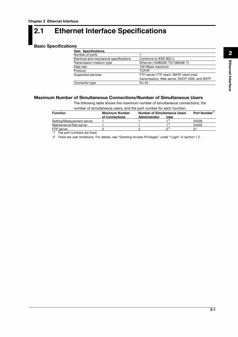
BasicSpecificationsItem Specifications Number of ports 1Electrical and mechanical specifications Conforms to IEEE 802.3.Transmission medium type Ethernet (100BASE-TX/10BASE-T)Data rate 100 Mbps maximumProtocol TCP/IPSupported services FTP server, FTP client, SMTP client (mail
transmission), Web server, DHCP, DNS, and SNTPConnector type RJ-45
Maximum Number of Simultaneous Connections/Number of Simultaneous UsersThe following table shows the maximum number of simultaneous connections, the number of simultaneous users, and the port number for each function.
Function Maximum Number Number of Simultaneous Users Port Number*1 of Connections Administrator User
Setting/Measurement server 1 1 1*2 34339Maintenance/Test server 1 1 1*2 34340FTP server 2 2 2*2 21*1 The port numbers are fixed.*2 There are user limitations. For details, see “Granting Access Privileges” under “Login” in section 1.2.
Chapter 2 Ethernet Interface
2-2
2.2 Connecting of the Ethernet Interface
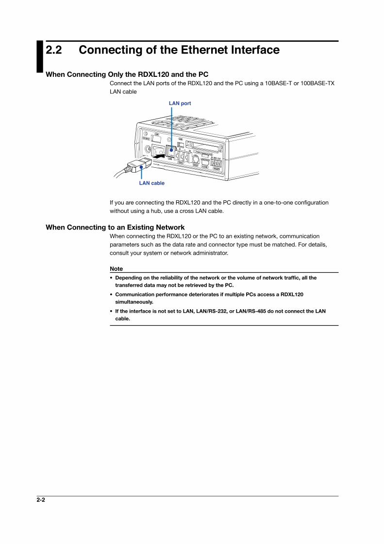
WhenConnectingOnlytheRDXL120andthePCConnect the LAN ports of the RDXL120 and the PC using a 10BASE-T or 100BASE-TX LAN cable
LOGIC/PULSE
ALARMRS232
LAN port
LAN cable
If you are connecting the RDXL120 and the PC directly in a one-to-one configuration without using a hub, use a cross LAN cable.
When Connecting to an Existing NetworkWhen connecting the RDXL120 or the PC to an existing network, communication parameters such as the data rate and connector type must be matched. For details, consult your system or network administrator.
Note• Dependingonthereliabilityofthenetworkorthevolumeofnetworktraffic,allthe
transferred data may not be retrieved by the PC.
• CommunicationperformancedeterioratesifmultiplePCsaccessaRDXL120 simultaneously.
• IftheinterfaceisnotsettoLAN,LAN/RS-232,orLAN/RS-485donotconnecttheLANcable.
2-3
Ethernet Interface
1
2
3
4
5
6
7
App
Index
2.3 Configuring of the Ethernet Interface
The following configurations must be made to use the Ethernet communication functions of the RDXL120.
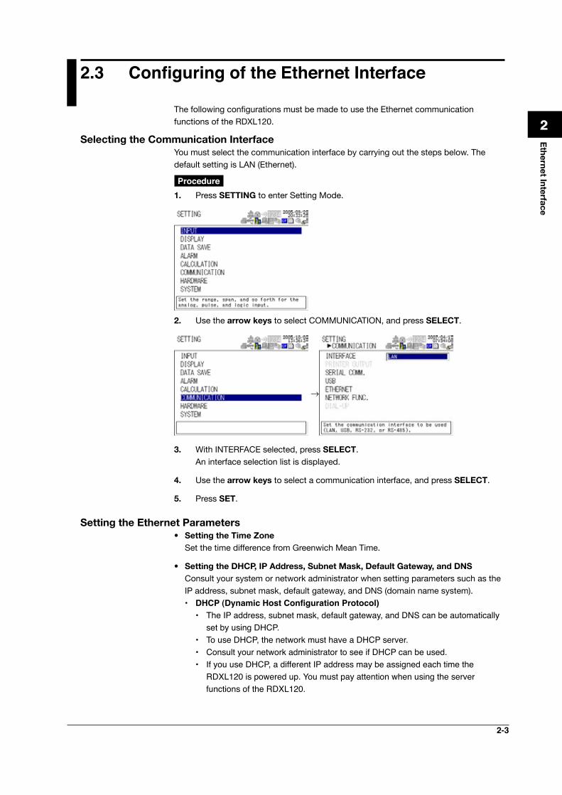
Selecting the Communication InterfaceYou must select the communication interface by carrying out the steps below. The default setting is LAN (Ethernet).
Procedure 1. Press SETTING to enter Setting Mode.
2. Use the arrow keys to select COMMUNICATION, and press SELECT.
→
3. With INTERFACE selected, press SELECT. An interface selection list is displayed.
4. Use the arrow keys to select a communication interface, and press SELECT.
5. Press SET.
Setting the Ethernet Parameters• SettingtheTime Zone Set the time difference from Greenwich Mean Time.
• SettingtheDHCP,IPAddress,SubnetMask,DefaultGateway,andDNS Consult your system or network administrator when setting parameters such as the
IP address, subnet mask, default gateway, and DNS (domain name system). • DHCP (Dynamic Host Configuration Protocol)
• The IP address, subnet mask, default gateway, and DNS can be automatically set by using DHCP.
• To use DHCP, the network must have a DHCP server.• Consult your network administrator to see if DHCP can be used.• If you use DHCP, a different IP address may be assigned each time the
RDXL120 is powered up. You must pay attention when using the server functions of the RDXL120.
2-4
• IP Address• Set the IP address to assign to the RDXL120. The default setting is 0.0.0.0.• The IP address is used to distinguish between the various devices connected
to the Internet when communicating using the TCP/IP protocol. The address is a 32-bit value expressed using four octets (each 0 to 255), each separated by a period as in [192.168.111.24].
• Subnet Mask• Specify the mask that is used to determine the network address from the IP
address. The default setting is 0.0.0.0.• Set the value according to the system or network to which the RDXL120
belongs. In some cases, this setting may not be necessary. • Default Gateway
• Set the IP address of the gateway (router, etc.) used to communicate with other networks. The default setting is 0.0.0.0.
• Set the value according to the system or network to which the RDXL120 belongs. In some cases, this setting may not be necessary.
• DNS (Domain Name System) You must set the DNS if you are using a host name to specify the destination
server of the file transfer on an FTP client or the server of the e-mail recipient.* DNS is a system used to associate names used on the Internet called host
names and domain names to IP addresses. The host name/domain name can be used instead of the IP address when accessing the network. The DNS server manages the database that contains the host name/domain name and IP address correlation.
• DNS Server• Set the IP address of the DNS server. The default setting is 0.0.0.0.• You can specify up to two DNS server IP addresses, primary and
secondary. If the primary DNS server is down, the secondary DNS server is automatically looked up for the mapping of the host name/domain name and IP address.
• Host Name Set the RDXL120’s host name using up to 64 characters.
• Domain Name• Set the network domain name that the RDXL120 belongs to using up to 64
characters.• When the destination server of the file transfer or the server of the e-mail
recipient is looked up using the DNS server, this domain name is appended to the host name as a possible domain name if it is omitted. The recipient name (server name) is set to the name specified by FTP Server Name or SMTP Server Name.
• Domain Suffix When the IP address corresponding to the server name with the domain name
of the previous section is not found, the system may be set up to search using a different domain name. In such cases, set the domain name to be searched following the “domain name” of the previous section as a domain suffix.• Set the domain suffix using up to 64 characters.• You can specify up to two domain suffixes, primary and secondary.
2.3 Configuring of the Ethernet Interface
2-5
Ethernet Interface
1
2
3
4
5
6
7
App
Index
Ethernet Interface
1
2
3
4
5
6
7
App
Index
• SettingtheSNTP (Time Synchronization Function) You can synchronize the standard clock by connecting to an SNTP server at power-
on and at specified timer intervals when the RDXL120 is in Free Running Mode using the Ethernet interface. The following items are set in addition to the Ethernet interface to use this function.
• SNTP ON/OFF Select whether to enable (ON) or disable (OFF) SNTP.
• Server Name Set the host name (set using FQDN) or IP address using up to 64 alphanumeric
characters. • Confirmation Time
Set the cycle for synchronizing the clock in the range of 1 to 24 hours.
• Enabling/DisablingtheLoginFunctionoftheRDXL120 The item below applies when the RDXL120 is used as a setting/measurement server
or maintenance/test server on the Ethernet interface. It does not apply to login when using the RDXL120 as an FTP server (see section 2.7).
If you enable the login function, only registered users can log in to the RDXL120.
• Communication Timeout The item below applies when the RDXL120 is used as a setting/measurement server
or maintenance/test server on the Ethernet interface. When using the RDXL120 as an FTP server, the connection is dropped when there is no data exchange for 5 minutes regardless of this setting.
• Selecting ON or OFF• ON Drops the connection when there is no data exchange for a given time.• OFF Communication timeout is disabled.
• Setting the Timeout Value If communication timeout is enabled, the connection is dropped if no data transfer
is detected over a time period specified here. Selectable range: 1 to 120 minutes
• Enabling/Disabling(On/Off)Keepalive• ON If there is no response to the inspection packet that is periodically transmitted
(every 30 s) at the TCP level, the connection is forcibly disconnected.• OFF Keepalive is disabled.
• SavingtheSettings To activate the settings that have been changed in the basic setting mode, the
settings must be saved. Otherwise, the settings that existed before the change are activated.
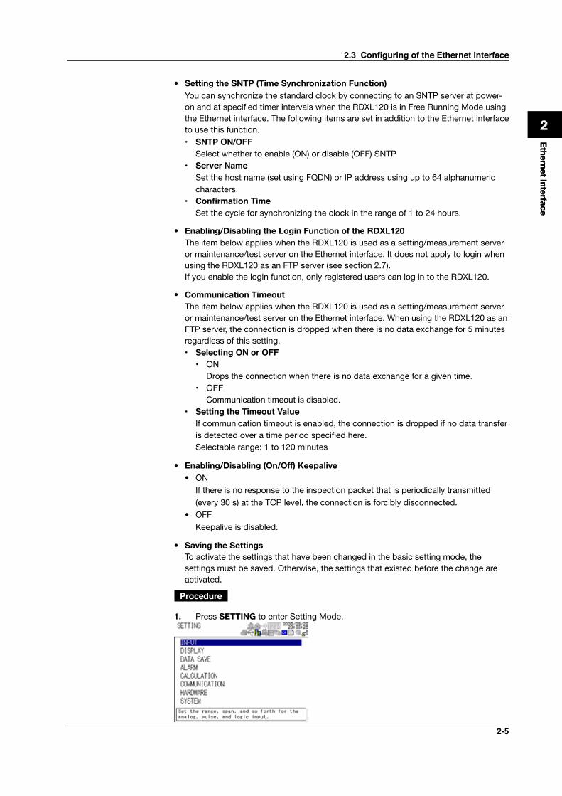
Procedure
1. Press SETTING to enter Setting Mode.
2.3 Configuring of the Ethernet Interface
2-6
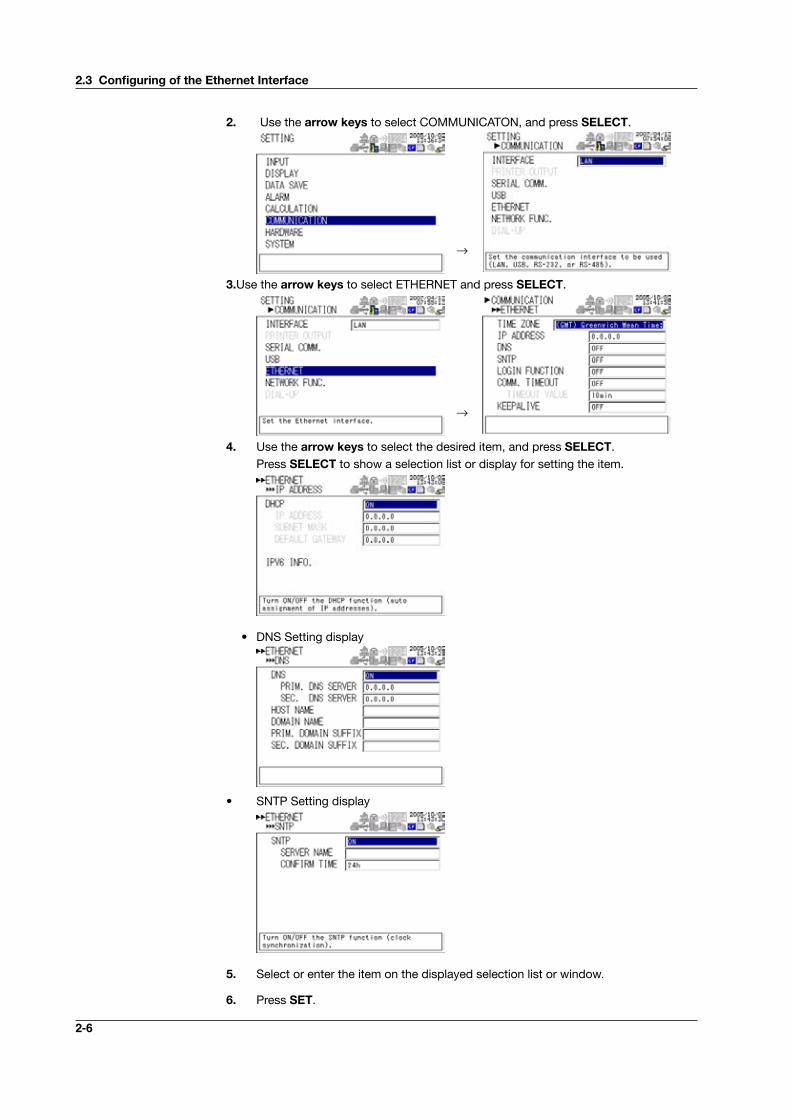
2. Use the arrow keys to select COMMUNICATON, and press SELECT.
→
3.Use the arrow keys to select ETHERNET and press SELECT.
→
4. Use the arrow keys to select the desired item, and press SELECT. Press SELECT to show a selection list or display for setting the item.
• IP Addess Setting display
• DNS Setting display
• SNTP Setting display
5. Select or enter the item on the displayed selection list or window.
6. Press SET.
2.3ConfiguringoftheEthernetInterface
2-7
Ethernet Interface
1
2
3
4
5
6
7
App
Index
Ethernet Interface
1
2
3
4
5
6
7
App
Index
2.4 Checking the Connection Status of the Ethernet Interface
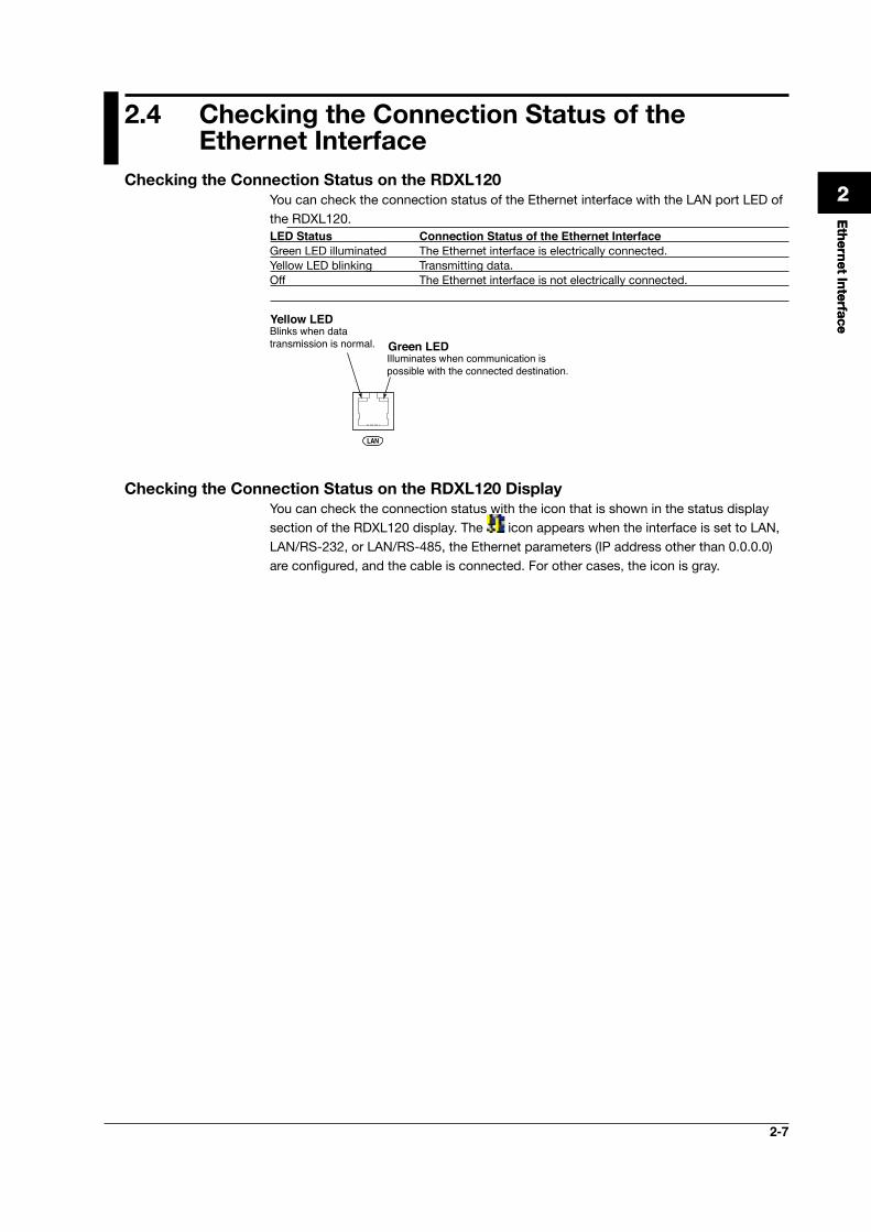
CheckingtheConnectionStatusontheRDXL120You can check the connection status of the Ethernet interface with the LAN port LED of the RDXL120.LED Status Connection Status of the Ethernet InterfaceGreen LED illuminated The Ethernet interface is electrically connected.Yellow LED blinking Transmitting data.Off The Ethernet interface is not electrically connected.
LAN
Green LEDBlinks when data transmission is normal.
Illuminates when communication is possible with the connected destination.
Yellow LED
CheckingtheConnectionStatusontheRDXL120DisplayYou can check the connection status with the icon that is shown in the status display section of the RDXL120 display. The icon appears when the interface is set to LAN, LAN/RS-232, or LAN/RS-485, the Ethernet parameters (IP address other than 0.0.0.0) are configured, and the cable is connected. For other cases, the icon is gray.
2-8
2.5 Setting the FTP Client (Setting the Auto Transfer ofMeasurementandAlarmDataFiles)
By setting this function, the measurement and alarm data files created in the internal memory of the RDXL120 or an external storage medium can be automatically transferred using FTP at the time the files are created. To use this function, however, the Ethernet interface must be configured as described in section 2.3.
• Selecting the Transferred Files• You can select whether to automatically transfer the measurement and alarm data
files. The default setting is OFF.• The data files are automatically transferred to the FTP destination explained in the
next section at the end of the logging operation or when a file is created (when the file division function is turned ON).
Note Ifafilewiththesamenameisdetectedatthedestination,thefileistransferredwiththelastcharacterofthefilenamechanged.
Example: Ifthefiletobetransferrednamed“050714130440.DLO”existsatthedestination,thefilenameischangedto“050714130440Fxxxx.DLO”(wherexxxxisavaluebetween0000and9999)beforeitistransferred.
• SettingtheFTPDestination Consult your system or network administrator when setting parameters such as the
primary/secondary FTP servers, port number, login name, password, account, and availability of the PASV mode.
• Specifying Primary and Secondary You can specify two destination FTP servers, primary and secondary. If the
primary server is down, the file is transferred to the secondary server. • FTP Server Name
Enter the name of the file transfer destination FTP server using up to 64 alphanumeric characters.• If the DNS is used, you can set the host name as a server name. For details on setting the DNS, see section 2.3, “Setting the Ethernet Interface.”• You can also set the IP address. In this case, the DNS is not required.
• Port Number Enter the port number of the file transfer destination FTP server in the range of 1
to 65535. The initial value is 21. • Login Name
Enter the login name for accessing the FTP server using up to 32 alphanumeric characters.
• Password Enter the password for accessing the FTP server using up to 32 alphanumeric
characters. • PASV Mode
Turn PASV mode ON when using the RDXL120 behind a firewall that requires the passive mode. The default setting is OFF. A firewall is furnished on a router (or a similar device) that has security features. It prevents intrusion from the outside into the network system.
2-9
Ethernet Interface
1
2
3
4
5
6
7
App
Index
Ethernet Interface
1
2
3
4
5
6
7
App
Index
• Initial Path Enter the directory of the file transfer destination using up to 64 alphanumeric
characters. The delimiter for directories varies depending on the implementation of the destination FTP server.
Example When transferring files to the “data” directory in the “home” directory of an FTP server on a UNIX file system.
/home/dataNote Ifthefiletransfertobothprimaryandsecondaryserversfails,theRDXL120abortsthefile
transfer. The data values (up to 16 data values) that failed to be transferred are transferred withanewdatafilewhentheconnectiontothedestinationrecovers.
Procedure
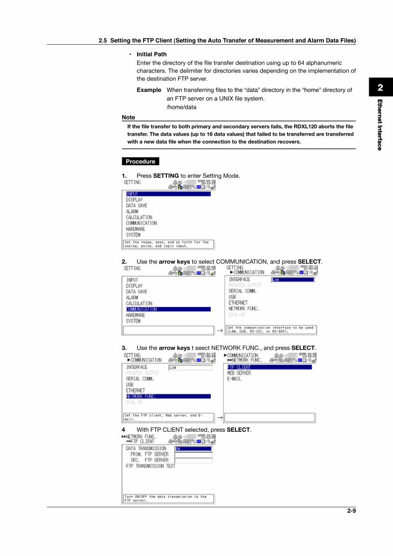
1. Press SETTING to enter Setting Mode.
2. Use the arrow keys to select COMMUNICATION, and press SELECT.
→
3. Use the arrow keys t seect NETWORK FUNC., and press SELECT.
→
4 With FTP CLIENT selected, press SELECT.
2.5 Setting the FTP Client (Setting the Auto Transfer of Measurement and Alarm Data Files)
2-10
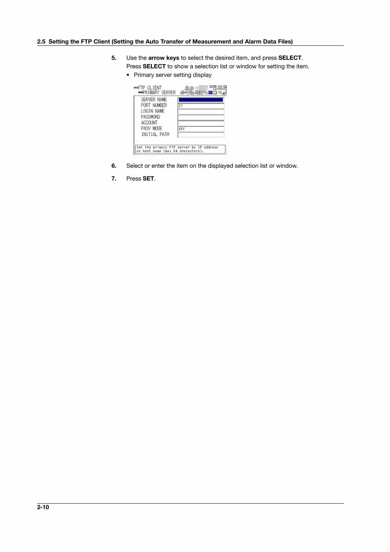
5. Use the arrow keys to select the desired item, and press SELECT. Press SELECT to show a selection list or window for setting the item. • Primary server setting display
6. Select or enter the item on the displayed selection list or window.
7. Press SET.
2.5SettingtheFTPClient(SettingtheAutoTransferofMeasurementandAlarmDataFiles)
2-11
Ethernet Interface
1
2
3
4
5
6
7
App
Index
2.6 FTP Test
You can test whether files can be transferred via the Ethernet interface by transferring a test file from the RDXL120 to the FTP server specified in section 2.5.
• ItemstoCheckbeforePerformingThisTest• Connect the Ethernet cable correctly. For the connection procedure, see section
2.2.• Check that the Ethernet interface settings are correct. For the procedure, see
section 2.3 or 2.5. When setting the Ethernet interface, check the settings with your system or network
administrator.
• CheckingtheResultsoftheFTPTest• When an FTP test is executed, a test file named FTPC.TXT is transferred to the
directory indicated by the initial path at the FTP destination specified in section 2.5.• The result of the FTP test can be confirmed by displaying the FTP log (displayed on
the RDXL120 (see section 2.8)) or Web screen (see section 2.10) or by outputting the result using the FL command (see section 4.8).
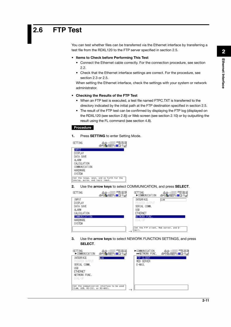
Procedure
1. Press SETTING to enter Setting Mode.
2. Use the arrow keys to select COMMUNICATION, and press SELECT.
→
3. Use the arrow keys to select NEWORK FUNCTION SETTINGS, and press SELECT.
→
2-12
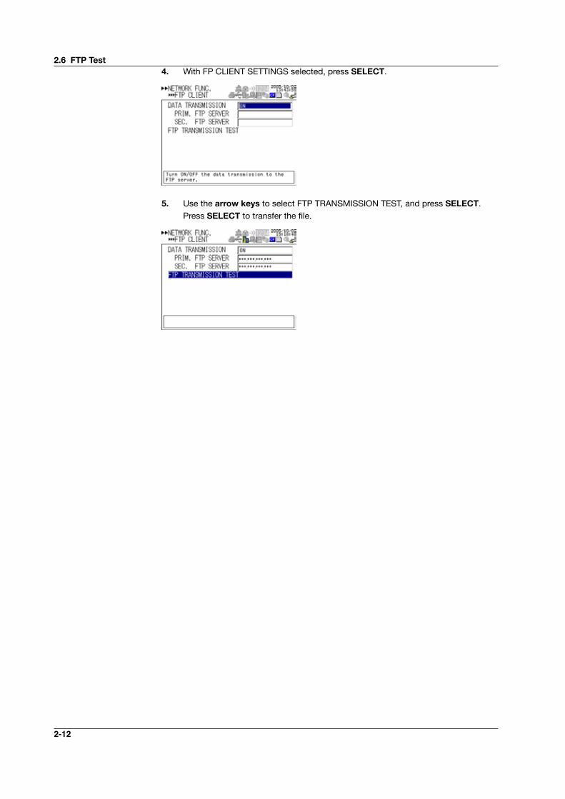
4. With FP CLIENT SETTINGS selected, press SELECT.
5. Use the arrow keys to select FTP TRANSMISSION TEST, and press SELECT. Press SELECT to transfer the file.
2.6 FTP Test
2-13
Ethernet Interface
1
2
3
4
5
6
7
App
Index
2.7 SettingtheLoginofEthernetCommunicationsBy setting these functions, you can prohibit access to the RDXL120 by third parties from the network, authorize setup operations of the RDXL120 via the Ethernet network, and disconnect connections if there is no data transmission for a given time. To use this function, however, the Ethernet interface must be configured as described in section 2.3.
Registering Users • Selecting the User Level
Select either user level, administrator or user.• Administrator One administrator can be registered. The administrator has the privileges to use
all the functions of the setting/measurement server, maintenance/test server, and FTP server.
• User Certain limitations exist in using the setting/measurement server, maintenance/
test server, and FTP server.• Limitations on the use of the setting/measurement server Users are not authorized to change the settings that would change the
operation of the RDXL120. Users can output measured and setting data.• Limitations on the use of the maintenance/test server A user cannot disconnect a connection between another PC and the
RDXL120. A user can disconnect the connection between the PC that the user is using and the RDXL120.
• Limitations on the use of the FTP server A user cannot save files to the external storage medium of the RDXL120 or
delete files on it. A user can load files. • Selecting Whether to Register (ON/OFF) Users
• ON Registers users. You can set the user name and password for logging in.• OFF Not register users.
• Setting the User Name• Enter the user name using up to 16 alphanumeric characters.• You cannot register the same user names.• Since the word “quit” is reserved as a command on the RDXL120, the user
name “quit” is not allowed.• Only the administrator is valid for the FTP server function. Login is not possible
even if a user is registered with administrator privileges. • Setting the Password
Set the password using up to six alphanumeric characters.
2-14
Note• TherelationshipbetweentheloginfunctionandtheusernameforaccessingtheRDXL120
is as follows:• WhenusingtheRDXL120asameasurement/settingserverormaintenance/testserver• WhentheloginfunctionontheEthernetsetupdisplayisON• YoucanlogintotheRDXL120usingtheregisteredusernameandpassword.• Theuserlevelistheuserlevelspecifiedwhentheusernamewasregistered.
• WhentheloginfunctionontheEthernetsetupdisplayisOFF• YoucanlogintotheRDXL120asanadministratorbyaccessingtheRDXL120usingtheusername“admin.”Nopasswordisnecessary.
• YoucanlogintotheRDXL120asauserbyaccessingtheRDXL120usingtheusername“user.”Nopasswordisnecessary.
• WhenusingtheRDXL120asaWebserver• WhenthemonitorpageaccessauthenticationontheWebserversetupdisplayisON,youcanlogintotheRDXL120usingaregisteredusernameandpassword.Theusernameandpasswordarenotnecessary,iftheaccessauthenticationisOFF.
• WhenthemonitorpageaccessauthenticationontheWebserversetupdisplayisON,youcanlogintotheRDXL120usingausernameandpasswordthatareregisteredwithadministratorprivileges.Theusernameandpasswordarenotnecessary,iftheaccess authentication is OFF.
• WhenusingtheRDXL120asanFTPserver• Onlytheadministratorand“anonymous”canusetheRDXL120.• Loginisnotpossibleusingtheusernameandpasswordofuser1touser6thataresetusingSYSTEM>USERREGISTEReveniftheyareregisteredwithadministratorprivileges.
• Nopasswordisnecessary(youcanloginregardlessofwhetherapasswordisen-tered)whenlogginginasanonymous.Theuserlevelissettouserprivileges.YoucanreadthefilesonthestoragemediumoftheRDXL120,butyoucannotwritefilesordeletefilesonthestoragemedium.
• WhenSYSTEM>USERREGISTER>ADMINISTRATOR>REGISTERissettoON• YoucanlogintotheRDXL120usingtheusernameandpasswordregisteredas
administrator.• AllfunctionsoftheFTPservercanbeusedwithadministratorprivileges.
• WhenSYSTEM>USERREGISTER>ADMINISTRATOR>REGISTERissettoOFF• YoucanlogintotheRDXL120withoutthepasswordbyaccessingtheRDXL120us-ingtheusername“admin.”
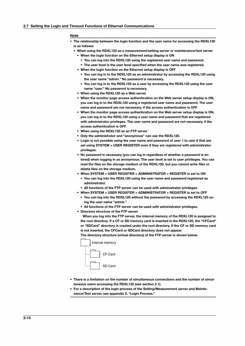
• AllfunctionsoftheFTPservercanbeusedwithadministratorprivileges.• DirectorystructureoftheFTPserver WhenyoulogintotheFTPserver,theinternalmemoryoftheRDXL120isassignedtotherootdirectory.IfaCForSDmemorycardisinsertedintheRDXL120,the“CFCard”or“SDCard”directoryiscreatedundertherootdirectory.IftheCForSDmemorycardisnotinserted,theCFCardorSDCarddirectorydoesnotappear.The directory structure (virtual directory) of the FTP server is shown below.
Internal memory
CF Card
SD Card
• Thereisalimitationonthenumberofsimultaneousconnectionsandthenumberofsimul-taneoususersaccessingtheRDXL120(seesection2.1).
• ForadescriptionoftheloginprocessoftheSetting/MeasurementserverandMainte-nance/Testserver,seeappendix2,“LoginProcess.”
2.7SettingtheLoginandTimeoutFunctionsofEthernetCommunications
2-15
Ethernet Interface
1
2
3
4
5
6
7
App
Index
Ethernet Interface
1
2
3
4
5
6
7
App
Index
Procedure
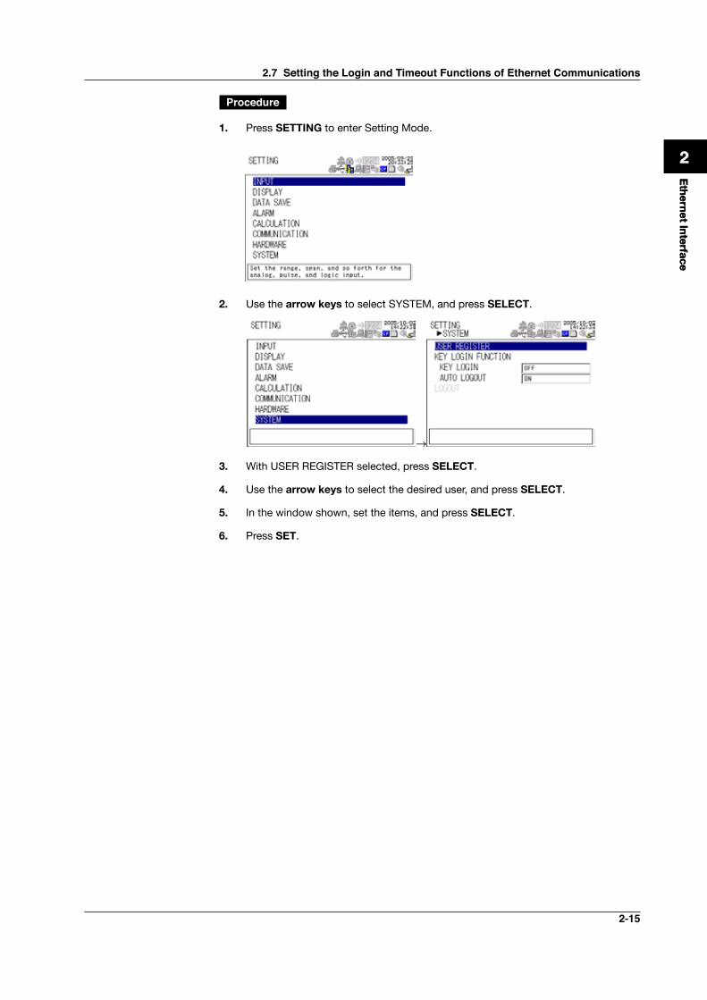
1. Press SETTING to enter Setting Mode.
2. Use the arrow keys to select SYSTEM, and press SELECT.
→
3. With USER REGISTER selected, press SELECT.
4. Use the arrow keys to select the desired user, and press SELECT.
5. In the window shown, set the items, and press SELECT.
6. Press SET.
2.7 Setting the Login and Timeout Functions of Ethernet Communications
2-16
2.8 ShowingtheError,Communication,andFTPLogDisplays
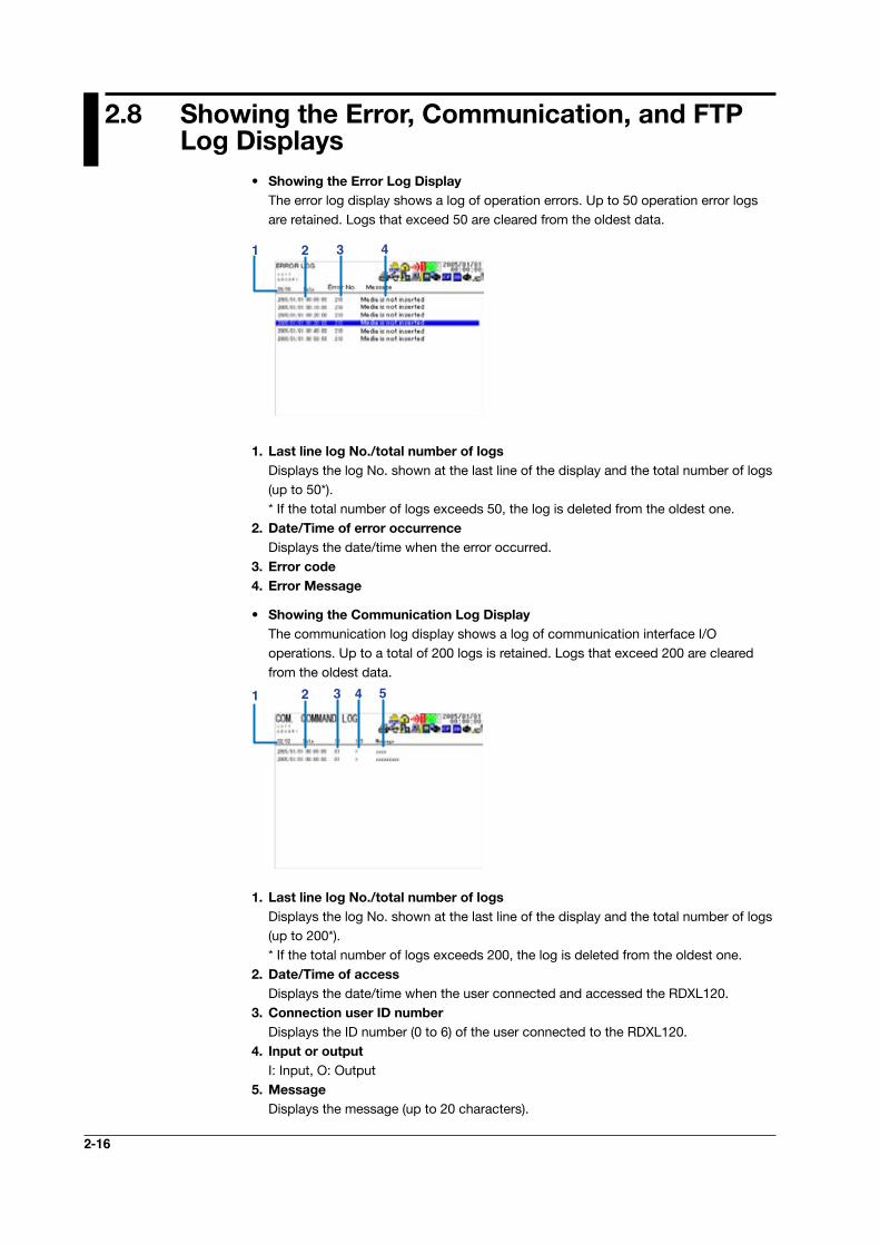
• ShowingtheErrorLogDisplay The error log display shows a log of operation errors. Up to 50 operation error logs
are retained. Logs that exceed 50 are cleared from the oldest data.
31 2 4
1. Last line log No./total number of logs Displays the log No. shown at the last line of the display and the total number of logs
(up to 50*). * If the total number of logs exceeds 50, the log is deleted from the oldest one.2.Date/Timeoferroroccurrence Displays the date/time when the error occurred.3.Errorcode4.ErrorMessage
• ShowingtheCommunicationLogDisplay The communication log display shows a log of communication interface I/O
operations. Up to a total of 200 logs is retained. Logs that exceed 200 are cleared from the oldest data.
31 2 4 5
1. Last line log No./total number of logs Displays the log No. shown at the last line of the display and the total number of logs
(up to 200*). * If the total number of logs exceeds 200, the log is deleted from the oldest one.2.Date/Timeofaccess Displays the date/time when the user connected and accessed the RDXL120.3.ConnectionuserIDnumber Displays the ID number (0 to 6) of the user connected to the RDXL120.4.Inputoroutput I: Input, O: Output5.Message Displays the message (up to 20 characters).
2-17
Ethernet Interface
1
2
3
4
5
6
7
App
Index
Ethernet Interface
1
2
3
4
5
6
7
App
Index
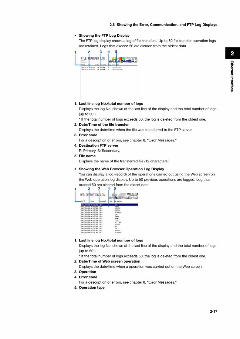
• ShowingtheFTPLogDisplay The FTP log display shows a log of file transfers. Up to 50 file transfer operation logs
are retained. Logs that exceed 50 are cleared from the oldest data.
31 2 4 5
1. Last line log No./total number of logs Displays the log No. shown at the last line of the display and the total number of logs
(up to 50*). * If the total number of logs exceeds 50, the log is deleted from the oldest one.2.Date/Timeofthefiletransfer Displays the date/time when the file was transferred to the FTP server.3.Errorcode For a description of errors, see chapter 8, “Error Messages.”4.DestinationFTPserver P: Primary. S: Secondary.5.Filename Displays the name of the transferred file (12 characters).
• ShowingtheWebBrowserOperationLogDisplay You can display a log (record) of the operations carried out using the Web screen on
the Web operation log display. Up to 50 previous operations are logged. Log that exceed 50 are cleared from the oldest data.
31 2 4 5
1. Last line log No./total number of logs Displays the log No. shown at the last line of the display and the total number of logs
(up to 50*). * If the total number of logs exceeds 50, the log is deleted from the oldest one.2.Date/TimeofWebscreenoperation Displays the date/time when a operation was carried out on the Web screen.3.Operation4.Errorcode For a description of errors, see chapter 8, “Error Messages.”5.Operationtype
2.8 Showing the Error, Communication, and FTP Log Displays
2-18
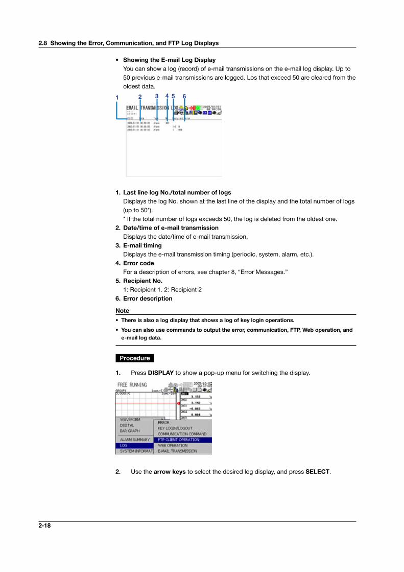
• ShowingtheE-mailLogDisplay You can show a log (record) of e-mail transmissions on the e-mail log display. Up to
50 previous e-mail transmissions are logged. Los that exceed 50 are cleared from the oldest data.
31 2 4 5 6
1. Last line log No./total number of logs Displays the log No. shown at the last line of the display and the total number of logs
(up to 50*). * If the total number of logs exceeds 50, the log is deleted from the oldest one.2.Date/timeofe-mailtransmission Displays the date/time of e-mail transmission.3.E-mailtiming Displays the e-mail transmission timing (periodic, system, alarm, etc.).4.Errorcode For a description of errors, see chapter 8, “Error Messages.”5.RecipientNo. 1: Recipient 1. 2: Recipient 26. Error description
Note• Thereisalsoalogdisplaythatshowsalogofkeyloginoperations.
• Youcanalsousecommandstooutputtheerror,communication,FTP,Weboperation,ande-mail log data.
Procedure
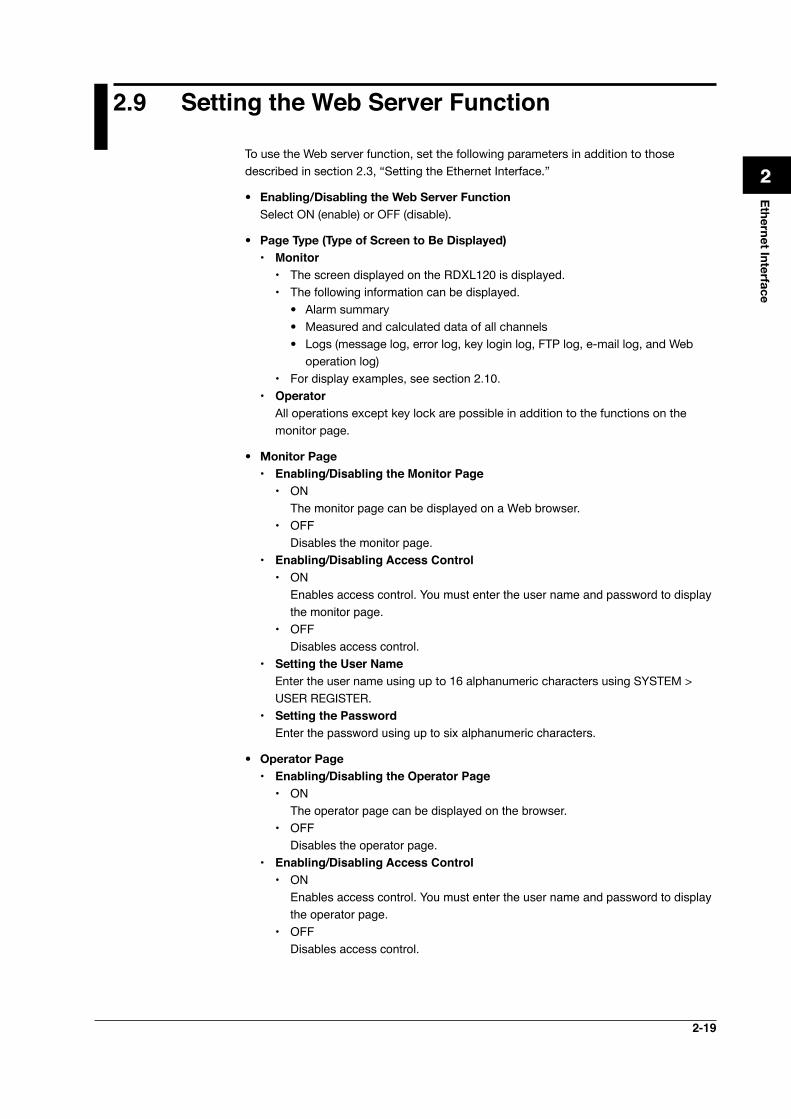
1. Press DISPLAY to show a pop-up menu for switching the display.
2. Use the arrow keys to select the desired log display, and press SELECT.
2.8ShowingtheError,Communication,andFTPLogDisplays
2-19
Ethernet Interface
1
2
3
4
5
6
7
App
Index
2.9 Setting the Web Server Function
To use the Web server function, set the following parameters in addition to those described in section 2.3, “Setting the Ethernet Interface.”
• Enabling/DisablingtheWebServerFunction Select ON (enable) or OFF (disable).
• PageType(TypeofScreentoBeDisplayed) • Monitor
• The screen displayed on the RDXL120 is displayed.• The following information can be displayed.
• Alarm summary• Measured and calculated data of all channels• Logs (message log, error log, key login log, FTP log, e-mail log, and Web
operation log)• For display examples, see section 2.10.
• Operator All operations except key lock are possible in addition to the functions on the
monitor page.
• Monitor Page • Enabling/Disabling the Monitor Page
• ON The monitor page can be displayed on a Web browser.• OFF Disables the monitor page.
• Enabling/Disabling Access Control• ON Enables access control. You must enter the user name and password to display
the monitor page.• OFF Disables access control.
• Setting the User Name Enter the user name using up to 16 alphanumeric characters using SYSTEM >
USER REGISTER. • Setting the Password
Enter the password using up to six alphanumeric characters.
• Operator Page • Enabling/Disabling the Operator Page
• ON The operator page can be displayed on the browser.• OFF Disables the operator page.
• Enabling/Disabling Access Control• ON Enables access control. You must enter the user name and password to display
the operator page.• OFF Disables access control.
2-20
• Setting the User Name Enter the user name using up to 16 alphanumeric characters using SYSTEM >
USER REGISTER. An administrator or a user with administrator privileges for Web browsing can
access the Web server function. • Setting the Password
Enter the password using up to six alphanumeric characters.
• SavingtheSettings To activate the settings that have been changed in the basic setting mode by
pressing the SET key, the settings must be saved. Otherwise, the settings that existed before the change are activated.
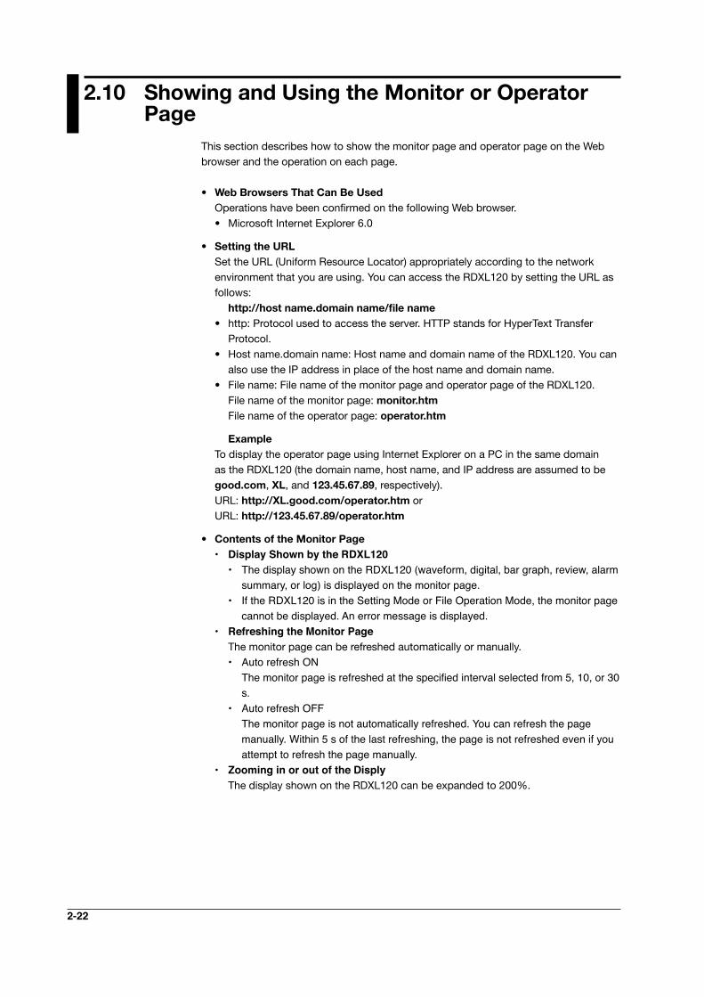
Procedure1. Press SETTING to enter Setting Mode.
2. Use the arrow keys to select COMMUNICATION, and press SELECT.
→
3. Use the arrow keys to select NETWORK FUNC., and press SELECT
→ 4. Use the arrow keys to select WEB SERVER, and press SELECT.
→
2.9SettingtheWeb Server Function

2-21
Ethernet Interface
1
2
3
4
5
6
7
App
Index
Ethernet Interface
1
2
3
4
5
6
7
App
Index
5. Use the arrow keys to select the desired item, and press SELECT. Press SELECT to show a selection list or window for setting the item.
6. Select or enter the item on the displayed selection list or window.
7. To enable access authentication, press SETTING, return to the display of step 1, and set the user using SYSTEM > USER REGISTER.
8. Press SET.
2.9 Setting the Web Server Function
2-22
2.10 ShowingandUsingtheMonitororOperatorPage
This section describes how to show the monitor page and operator page on the Web browser and the operation on each page.
• Web Browsers That Can Be Used Operations have been confirmed on the following Web browser.
• Microsoft Internet Explorer 6.0
• Setting the URL Set the URL (Uniform Resource Locator) appropriately according to the network
environment that you are using. You can access the RDXL120 by setting the URL as follows:
http://hostname.domainname/filename• http: Protocol used to access the server. HTTP stands for HyperText Transfer
Protocol.• Host name.domain name: Host name and domain name of the RDXL120. You can
also use the IP address in place of the host name and domain name.• File name: File name of the monitor page and operator page of the RDXL120. File name of the monitor page: monitor.htm File name of the operator page: operator.htm
Example To display the operator page using Internet Explorer on a PC in the same domain
as the RDXL120 (the domain name, host name, and IP address are assumed to be good.com, XL, and 123.45.67.89, respectively).
URL: http://XL.good.com/operator.htm or URL: http://123.45.67.89/operator.htm
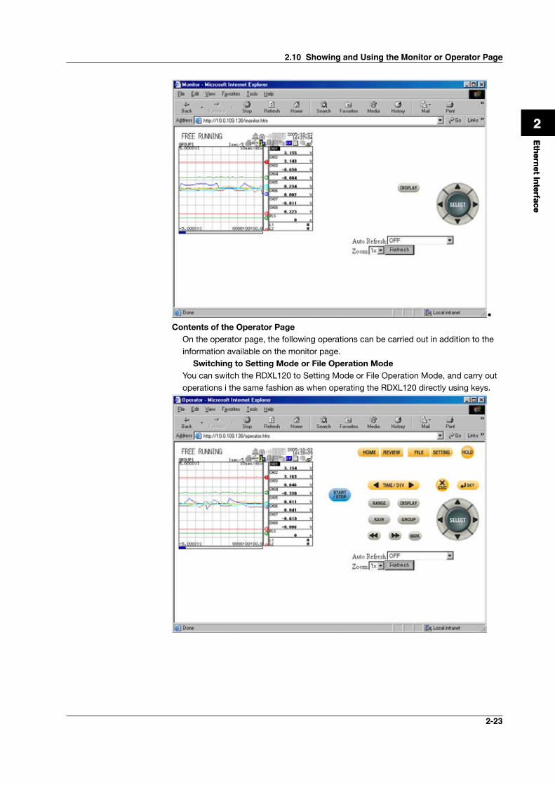
• ContentsoftheMonitor Page • Display Shown by the RDXL120
• The display shown on the RDXL120 (waveform, digital, bar graph, review, alarm summary, or log) is displayed on the monitor page.
• If the RDXL120 is in the Setting Mode or File Operation Mode, the monitor page cannot be displayed. An error message is displayed.
• Refreshing the Monitor Page The monitor page can be refreshed automatically or manually.
• Auto refresh ON The monitor page is refreshed at the specified interval selected from 5, 10, or 30
s.• Auto refresh OFF The monitor page is not automatically refreshed. You can refresh the page
manually. Within 5 s of the last refreshing, the page is not refreshed even if you attempt to refresh the page manually.
• Zooming in or out of the Disply The display shown on the RDXL120 can be expanded to 200%.
2-23
Ethernet Interface
1
2
3
4
5
6
7
App
Index
Ethernet Interface
1
2
3
4
5
6
7
App
Index
•Contents of the Operator Page On the operator page, the following operations can be carried out in addition to the
information available on the monitor page. Switching to Setting Mode or File Operation Mode You can switch the RDXL120 to Setting Mode or File Operation Mode, and carry out
operations i the same fashion as when operating the RDXL120 directly using keys.
2.10 Showing and Using the Monitor or Operator Page
2-24
2.11 Setting the E-mail Transmission Function
To use the e-mail transmission function, set the following parameters in addition to those described in section 2.3, “Setting the Ethernet Interface.”
• BasicSettingsofE-mailTransmission • SMTP* Server Name
Set the SMTP server name (up to 64 alphanumeric characters) or the IP address of the SMTP server.
* Simple Mail Transfer Protocol
• Port NumberSet the port number to be used. The default setting is 25.
• Recipient 1 Set the recipient of the e-mail message using up to 150 alphanumeric characters.
You can specify multiple addresses. To specify multiple addresses, delimit the addresses using commas.
• Recipient 2 Set the recipient of the e-mail message using up to 150 alphanumeric characters.
You can specify multiple addresses. To specify multiple addresses, delimit the addresses using commas.
• Sender Set the e-mail address that has been provided by the network administrator using
up to 64 alphanumeric characters. If omitted, the sender is set to the first address specified as the recipient.
• Mail Authentication • Mail Authentication
If you require POP before SMTP for e-mail transmission set POP authentication. • POP AUTHENTICATION
Use the POP authentication. • OFF
Not use the POP authentication. • Server Name
Set the POP server name (up to 64 alphanumeric characters) or the IP address of the POP server.
• Account Name Set the account name for the POP server using up to 32 alphanumeric
characters. • Password
Set the password for the POP server using up to 32 alphanumeric characters.
Note POP authentication (POP before SMTP) is one of the user authentication methods for sendinge-mail.AccesstotheSMTPserverisgrantedbyaccessingthespecificPOP3serverfirstbeforesendingthee-mail.
BecauseSMTPdoesnothaveauserauthenticationfunction,itisoftenusedtosendspammail.ByusingPOPtoreceivemailthroughauthenticationinadvance,itallowstheIPaddressoftheusertobeaccessiblefortransmissiononlyforagivenperiod.Asaresult,such abuse can be prohibited.
2-25
Ethernet Interface
1
2
3
4
5
6
7
App
Index
Ethernet Interface
1
2
3
4
5
6
7
App
Index
• SettingsforTransmittingAlarmInformation • Recipient 1, Recipient 2
You can turn ON/OFF the function for each recipient.• ON Transmits e-mail messages to the recipient.• OFF Does not transmit e-mail messages to the recipient.
• Contents of the Transmitted Mail • Add Inst. Data
• ON The instantaneous values of all channels are included in the e-mail message.• Off The instantaneous values are not included in the e-mail message.
• Add Source URL (Uniform Resource Locator)• ON If the Web server function is specified on the RDXL120, the URL of the
RDXL120 is attached to the e-mail.• OFF The URL of the RDXL120 is not attached to the e-mail.
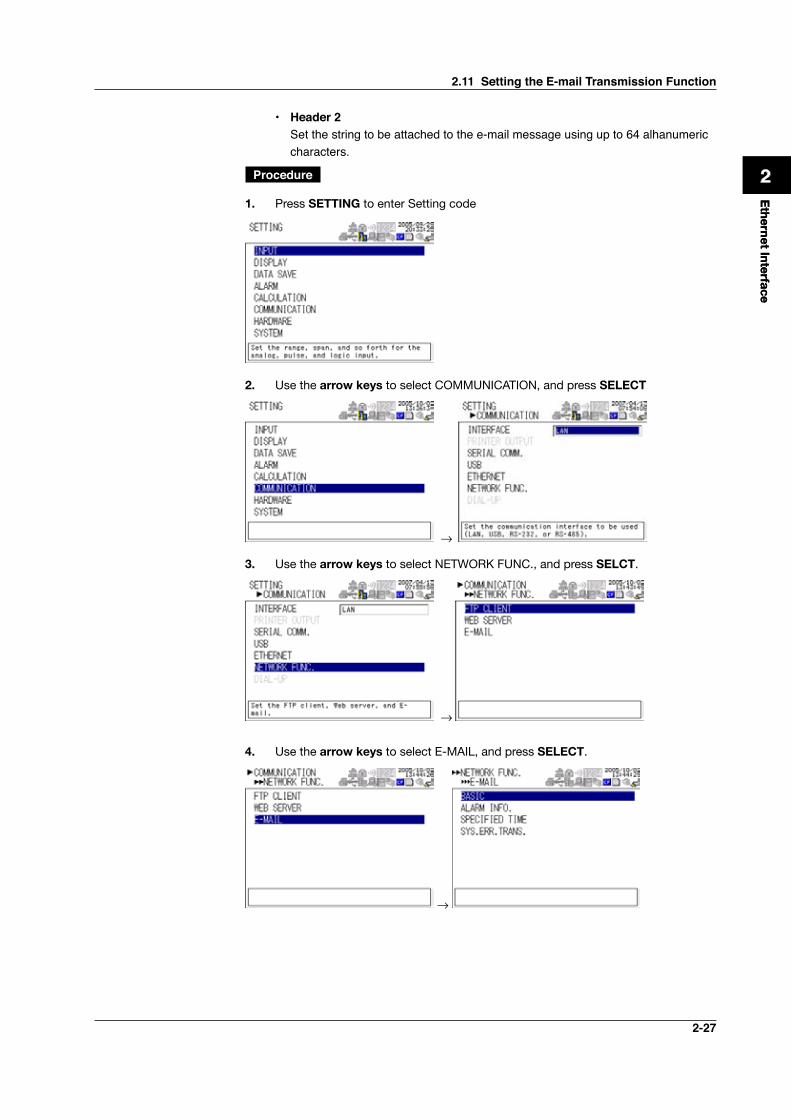
• Subject Set the subject of the e-mail message using up to 32 alphanumeric characters.
The default setting is “(RDXL120)Alarm_summary.” • Header 1
Set the string to be attached to the e-mail message using up to 64 alphanumeric characters.
• Header 2 Set the string to be attached to the e-mail message using up to 64 alphanumeric
characters.
• SettingsWhenTransmittingE-mailMessagesattheSpecifiedTime • Recipient 1, Recipient 2
You can turn ON/OFF the function for each recipient.• ON Transmits e-mail messages to the recipient.• OFF Does not transmit e-mail messages to the recipient.
• Interval Time interval used to repeat the e-mail transmission starting from the REFERENCE
TIME. Select from the following: 1h, 2h, 3h, 4h, 6h, 8h, 12h, or 24h
• REFERENCE TIME The time when the e-mail message is to be transmitted. In addition, the e-mail
transmission is repeated at the specified interval from this point. Specify the time in the following range for each recipient.
00:00 to 23:59Example: If Reference time is 17:15 and Interval is 8h, e-mail messages are
transmitted at 17:15, 01:15, and 09:15.
2.11 Setting the E-mail Transmission Function
2-26
• Contents of the Transmitted Mail • Add Inst. Data
• ON Attaches to the e-mail message the instantaneous values of all channels
existing at the time of e-mail transmission.• OFF The instantaneous values are not attached to the e-mail message.
• Add Source URL (Uniform Resource Locator)• ON If the Web server function is specified on the RDXL120, the URL of the
RDXL120 is attached to the e-mail.• OFF The URL of the RDXL120 is not attached to the e-mail.
• Subject Set the subject of the e-mail message using up to 32 alphanumeric characters.
The default value is “(RDXL120)Periodic_data.” • Header 1
Set the string to be attached to the e-mail message using up to 64 alphanumeric characters.
• Header 2 Set the string to be attached to the e-mail message using up to 64 alphanumeric
characters.
• SettingsWhenTransmittingE-mailMessagesattheTimeofRecoveryfromaPower Failure (System Error Settings)
For the transmitted contents of the system mail, see section 1.2. • Recipient 1, Sender
You can turn ON/OFF the function for each recipient.• ON
Transmits e-mail messages to the recipient.• OFF Does not transmit e-mail messages to the recipient.
• Contents of the Transmitted Mail • Include INST
• ON Adds to the e-mail message the instantaneous values of all channels existing
at the time of e-mail transmission.• OFF The instantaneous values are not added to the e-mail message.
• Include Source URL (Uniform Resource Locator)• ON If the Web server function is specified on the RDXL120, the URL of the
RDXL120 is attached to the e-mail.• OFF The URL of the RDXL120 is not attached to the e-mail.
• Subject Set the subject of the e-mail message using up to 32 alphanumeric characters.
The default setting is “(RDXL120)System_warning.” • Header 1
Set the string to be attached to the e-mail message using up to 64 alphanumeric characters.
2.11 Setting the E-mail Transmission Function
2-27
Ethernet Interface
1
2
3
4
5
6
7
App
Index
Ethernet Interface
1
2
3
4
5
6
7
App
Index
• Header 2 Set the string to be attached to the e-mail message using up to 64 alhanumeric
characters.
Procedure
1. Press SETTING to enter Setting code
2. Use the arrow keys to select COMMUNICATION, and press SELECT
→
3. Use the arrow keys to select NETWORK FUNC., and press SELCT.
→
4. Use the arrow keys to select E-MAIL, and press SELECT.
→
2.11 Setting the E-mail Transmission Function
2-28
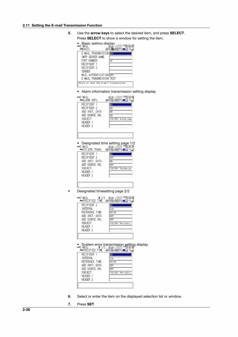
5. Use the arrow keys to select the desired item, and press SELECT. Press SELECT to show a window for setting the item. • Basic setting display
• Alarm information transmission setting display
• Designated time setting page 1/2
• Designated timesetting page 2/2
• System error transmission setting display
6. Select or enter the item on the displayed selection list or window.
7. Press SET.
2.11 Setting the E-mail Transmission Function
2-29
Ethernet Interface
1
2
3
4
5
6
7
App
Index
Ethernet Interface
1
2
3
4
5
6
7
App
Index
2.12 E-mail Transmission Test
You can transmit test e-mail messages to recipient 1 or recipient 2 that you specified to confirm whether e-mail messages can be transmitted.
• ItemstoCheckbeforePerformingThisTest• Connect the Ethernet cable correctly. For the connection procedure, see section
2.2.• Check that the Ethernet interface settings are correct. For the procedure, see
section 2.3.• Check that the e-mail settings are correct. For the procedure, see section 2.11.
When setting the Ethernet interface or e-mail, check the settings with your system or network administrator.
• CheckingtheResultsoftheE-mailTransmissionTest• The result of the e-mail transmission test can be confirmed by displaying the
e-mail log (displayed on the RDXL120 (see section 2.8)) or Web screen (see section 2.10) or by outputting the result using the FL command (see section 5.9).
• If an error message is displayed on the RDXL120, see chapter 8, “Error Messages.”
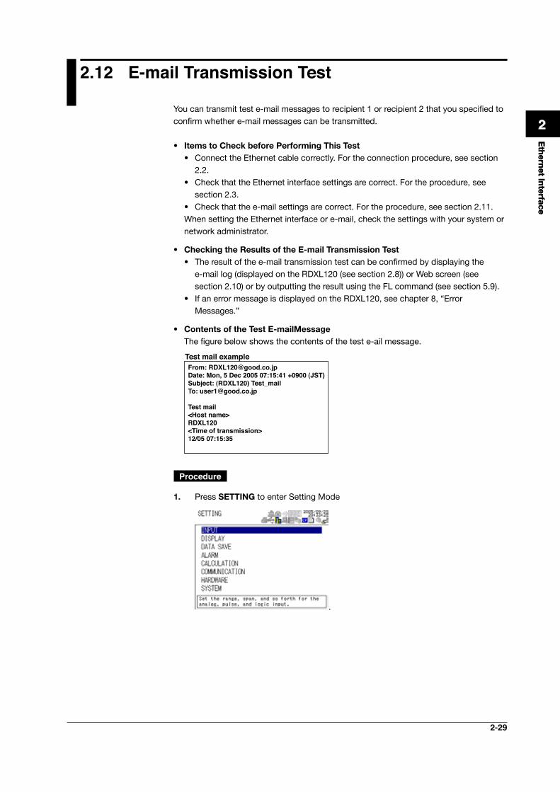
• ContentsoftheTestE-mailMessage The figure below shows the contents of the test e-ail message.
From: [email protected]: Mon, 5 Dec 2005 07:15:41 +0900 (JST)Subject: (RDXL120) Test_mailTo: [email protected]
Test mail<Host name>RDXL120<Time of transmission>12/05 07:15:35
Test mail example
Procedure
1. Press SETTING to enter Setting Mode
.
2-30
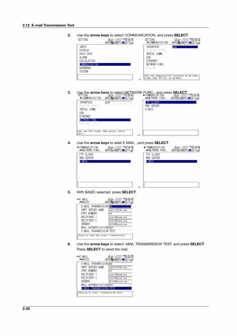
2. Use the arrow keys to select COMMUNICATION, and press SELECT.
→
3. Use the arrow keys to select NETWORK FUNC., and press SELECT.
→
4. Use the arrow keys to selet E-MAIL , and press SELECT.
→5. With BASIC selected, press SELECT.
6. Use the arrow keys to select -MAIL TRANSMISSION TEST, and press SELECT. Press SELECT to send the mail.
2.12 E-mail Transmission Test
2-31
Ethernet Interface
1
2
3
4
5
6
7
App
Index
2.13 Starting/Stopping E-mail Transmissions
• Starting/Stopping E-mail Transmissions• If E-MAIL SETTINGS > BASIC SETTINGS > E-MAIL TRANSMISSION is turned ON,
the e-mail transmission function is enabled.• If E-MAIL SETTINGS > BASIC SETTINGS > E-MAIL TRANSMISSION is turned
OFF, the e-mail transmission function is disabled. Unsent e-mail messages are cleared.
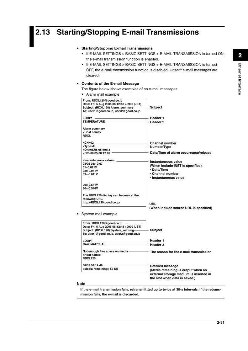
• Contents of the E-mail Message The figure below shows examples of an e-mail messages.
• Alarm mail example
From: [email protected]: Fri, 5 Aug 2005 08:12:48 +0900 (JST)Subject: (RDXL120) Alarm_summaryTo: [email protected], [email protected]
LOOP1TEMPERATURE
Alarm summary<Host name>RDXL
<CH>02<Type>1L<On>08/05 08:10:13<Off>08/05 08:12:07
<Instantaneous value>08/05 08:12:0701=0.021V02=-0.041V03=-0.011V • •29=-0.541V30=-0.546V
The RDXL120 display can be seen at the following URL.http://RDXL120.good.co.jp/
Header 1
Subject
Header 2
Channel numberNumber/TypeDate/Time of alarm occurrence/release
Instantaneous value(When Include INST is specified)• Date/Time• Channel number• Instantaneous value
URL(When Include source URL is specified)
• System mail example
From: [email protected]: Fri, 5 Aug 2005 08:12:48 +0900 (JST)Subject: (RDXL120) System_warningTo: [email protected], [email protected]
LOOP1RAW MATERIAL
Not enough free space on media<Host name>RDXL120
08/05 08:12:48<Media remaining> 53 KB
Header 1
Subject
Header 2
The reason for the e-mail transmission
Detailed message(Media remaining is output when an external storage medium is inserted in the slot when data is saved.)
Note Ifthee-mailtransmissionfails,retransmittteduptotwiceat30-sintervals.Iftheretrans-missionfails,thee-mailisdiscarded.
3-1
3.1 RS-232 Interface Specifications and Setup Procedure
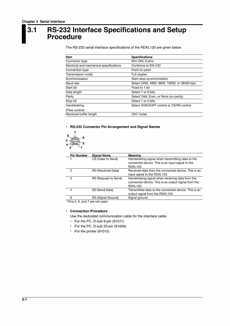
The RS-232 serial interface specifications of the RDXL120 are given below.
Item Specifications Connector type Mini DIN, 8 pins Electrical and mechanical specifications Conforms to EIA-232Connection type Point-to-pointTransmission mode Full-duplexSynchronization Start-stop synchronizationBaud rate Select 2400, 4800, 9600, 19200, or 38400 bps.Start bit Fixed to 1 bitData length Select 7 or 8 bitsParity Select Odd, Even, or None (no parity).Stop bit Select 1 or 2 bitsHandshaking Select XON/XOFF control or CS/RS control
(Flow control)Received buffer length 2047 bytes
• RS-232 Connector Pin Arrangement and Signal Names
13
67
854
2
Pin Number Signal Name Meaning1 CS (Clear to Send) Handshaking signal when transmitting data to the
connected device. This is an input signal to the RDXL120.
2 RD (Received Data) Received data from the connected device. This is an input signal to the RDXL120.
3 RS (Request to Send) Handshaking signal when receiving data from the connected device. This is an output signal from the RDXL120.
4 SD (Send Data) Transmitted data to the connected device. This is an output signal from the RDXL120.
8 SG (Signal Ground) Signal ground.* Pins 5, 6, and 7 are not used.
• Connection Procedure Use the dedicated communication cable for the interface cable.
• For the PC. D-sub 9-pin (91011)• For the PC. D-sub 25-pin (91009)• For the printer (91010)
Chapter 3 Serial Interface
3-2
1
2
3
4
5
6
7
App
Index
Serial Interface
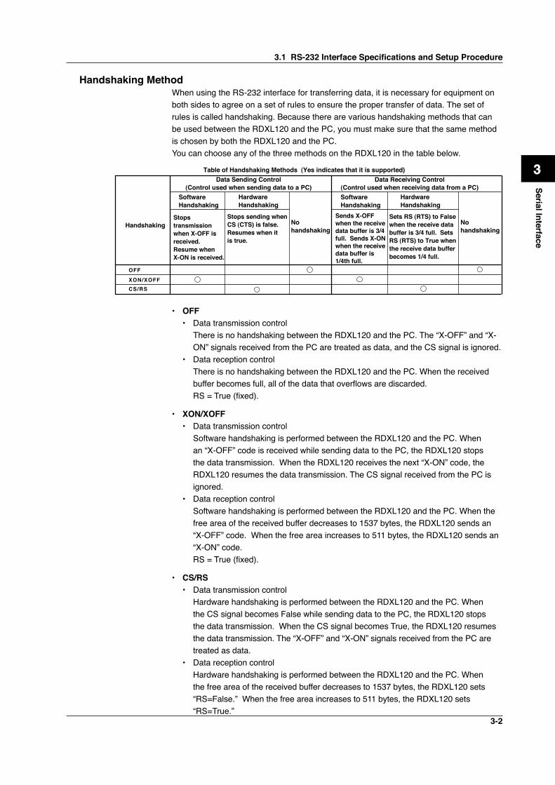
Handshaking MethodWhen using the RS-232 interface for transferring data, it is necessary for equipment on both sides to agree on a set of rules to ensure the proper transfer of data. The set of rules is called handshaking. Because there are various handshaking methods that can be used between the RDXL120 and the PC, you must make sure that the same method is chosen by both the RDXL120 and the PC.You can choose any of the three methods on the RDXL120 in the table below.
Data Sending Control(Control used when sending data to a PC)
Data Receiving Control(Control used when receiving data from a PC)
Software Handshaking
Software Handshaking
Table of Handshaking Methods (Yes indicates that it is supported)
OFF
XON/XOFFCS/RS
HandshakingStops transmission when X-OFF is received. Resume when X-ON is received.
Stops sending when CS (CTS) is false. Resumes when it is true.
No handshaking
No handshaking
Sends X-OFF when the receive data buffer is 3/4 full. Sends X-ON when the receive data buffer is 1/4th full.
Sets RS (RTS) to False when the receive data buffer is 3/4 full. Sets RS (RTS) to True when the receive data buffer becomes 1/4 full.
Hardware Handshaking
Hardware Handshaking
• OFF• Data transmission control There is no handshaking between the RDXL120 and the PC. The “X-OFF” and “X-
ON” signals received from the PC are treated as data, and the CS signal is ignored.• Data reception control There is no handshaking between the RDXL120 and the PC. When the received
buffer becomes full, all of the data that overflows are discarded. RS = True (fixed).
• XON/XOFF• Data transmission control Software handshaking is performed between the RDXL120 and the PC. When
an “X-OFF” code is received while sending data to the PC, the RDXL120 stops the data transmission. When the RDXL120 receives the next “X-ON” code, the RDXL120 resumes the data transmission. The CS signal received from the PC is ignored.
• Data reception control Software handshaking is performed between the RDXL120 and the PC. When the
free area of the received buffer decreases to 1537 bytes, the RDXL120 sends an “X-OFF” code. When the free area increases to 511 bytes, the RDXL120 sends an “X-ON” code.
RS = True (fixed).
• CS/RS• Data transmission control Hardware handshaking is performed between the RDXL120 and the PC. When
the CS signal becomes False while sending data to the PC, the RDXL120 stops the data transmission. When the CS signal becomes True, the RDXL120 resumes the data transmission. The “X-OFF” and “X-ON” signals received from the PC are treated as data.
• Data reception control Hardware handshaking is performed between the RDXL120 and the PC. When
the free area of the received buffer decreases to 1537 bytes, the RDXL120 sets “RS=False.” When the free area increases to 511 bytes, the RDXL120 sets “RS=True.”
3.1 RS-232 Interface Specifications and Setup Procedure
3-3
Precautions Regarding Data Reception ControlWhen handshaking is used to control the reception of data, data may still be sent from the PC even if the free space in the receive buffer drops below 256 bytes. In this case, after the receive buffer becomes full, the excess data will be lost, whether or not handshaking is in effect. Data storage of data resumes when there is free space in the buffer.
Setting the RS-232 Interface• Selecting the Slave Address Select the address from the following values. 1 to 247
• Selecting the Baud Rate Select the baud rate from the following: 2400, 4800, 9600, 19200, or 38400
• Setting the Data Length Select the data length from below. To output data in binary format, be sure to set the
data length to 8 bits. 7 or 8
• Setting the Stop Bit Select the stop bit from the following: 1 or 2
• Selecting the Parity Check Select the parity check from the following: ODD, EVEN, or NONE
• Selecting the handshaking Select the handshaking method from the following. OFF, XON/XOFF, or CS/RS
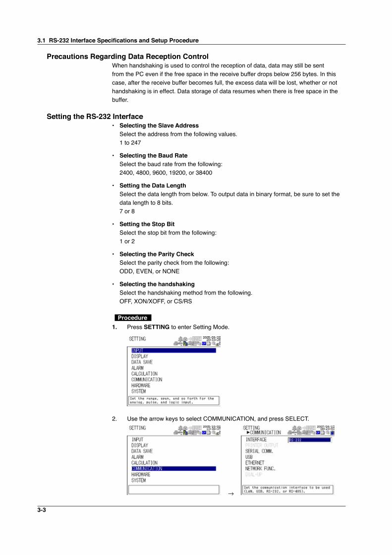
Procedure 1. Press SETTING to enter Setting Mode.
2. Use the arrow keys to select COMMUNICATION, and press SELECT.
→
3.1 RS-232 Interface Specifications and Setup Procedure
3-4
1
2
3
4
5
6
7
App
Index
Serial Interface
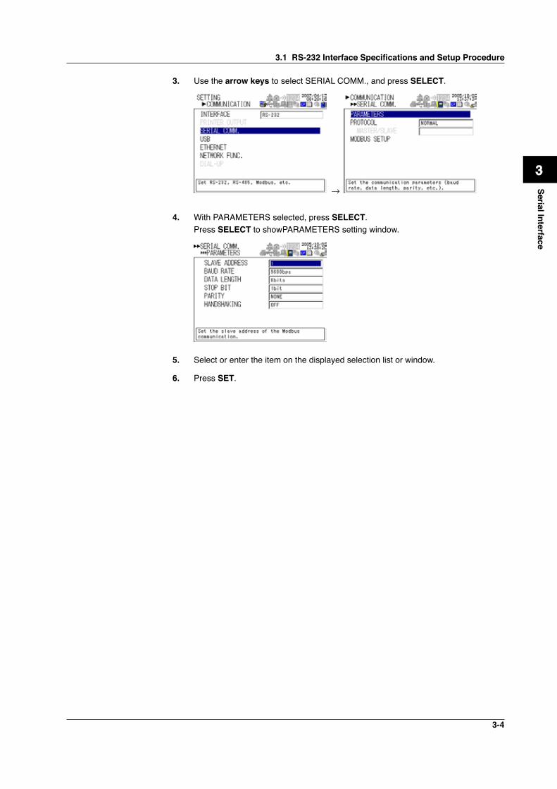
3. Use the arrow keys to select SERIAL COMM., and press SELECT.
→
4. With PARAMETERS selected, press SELECT. Press SELECT to showPARAMETERS setting window.
5. Select or enter the item on the displayed selection list or window.
6. Press SET.
3.1 RS-232 Interface Specifications and Setup Procedure
3-5
3.2 RS-485 Interface Specifications and Setup Procedure
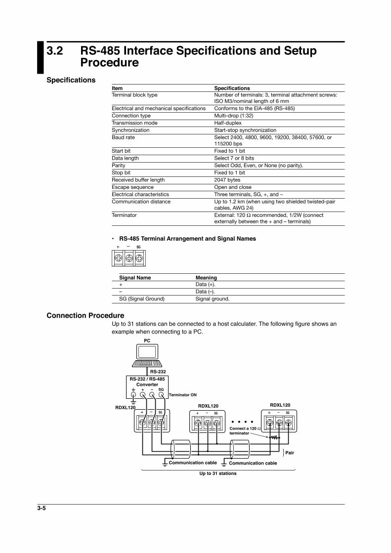
SpecificationsItem Specifications Terminal block type Number of terminals: 3, terminal attachment screws:
ISO M3/nominal length of 6 mm Electrical and mechanical specifications Conforms to the EIA-485 (RS-485)Connection type Multi-drop (1:32)Transmission mode Half-duplexSynchronization Start-stop synchronizationBaud rate Select 2400, 4800, 9600, 19200, 38400, 57600, or
115200 bpsStart bit Fixed to 1 bitData length Select 7 or 8 bitsParity Select Odd, Even, or None (no parity).Stop bit Fixed to 1 bitReceived buffer length 2047 bytesEscape sequence Open and closeElectrical characteristics Three terminals, SG, +, and –Communication distance Up to 1.2 km (when using two shielded twisted-pair
cables, AWG 24)Terminator External: 120 Ω recommended, 1/2W (connect
externally between the + and – terminals)
• RS-485 Terminal Arrangement and Signal NamesSG
Signal Name Meaning+ Data (+).– Data (–).SG (Signal Ground) Signal ground.
Connection Procedure Up to 31 stations can be connected to a host calculater. The following figure shows an example when connecting to a PC.
RS-232 / RS-485Converter
+ – SG
SG
RDXL120
PC
RS-232
Terminator ON
Connect a 120 Ω terminator
Communication cable Communication cable
Pair
Up to 31 stations
RDXL120RDXL120SGSGSG
SGSG
3-6
1
2
3
4
5
6
7
App
Index
Serial Interface
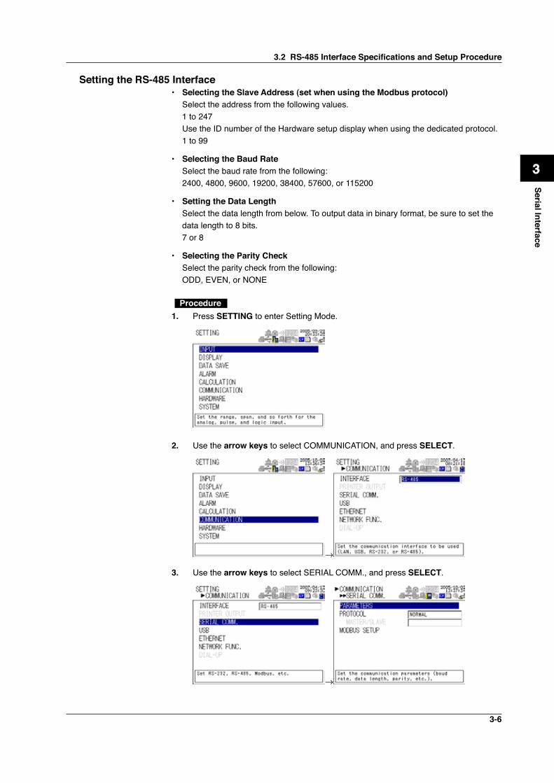
Setting the RS-485 Interface• Selecting the Slave Address (set when using the Modbus protocol) Select the address from the following values. 1 to 247 Use the ID number of the Hardware setup display when using the dedicated protocol. 1 to 99
• Selecting the Baud Rate Select the baud rate from the following: 2400, 4800, 9600, 19200, 38400, 57600, or 115200
• Setting the Data Length Select the data length from below. To output data in binary format, be sure to set the
data length to 8 bits. 7 or 8
• Selecting the Parity Check Select the parity check from the following: ODD, EVEN, or NONE
Procedure1. Press SETTING to enter Setting Mode.
2. Use the arrow keys to select COMMUNICATION, and press SELECT.
→
3. Use the arrow keys to select SERIAL COMM., and press SELECT.
→
3.2 RS-485 Interface Specifications and Setup Procedure
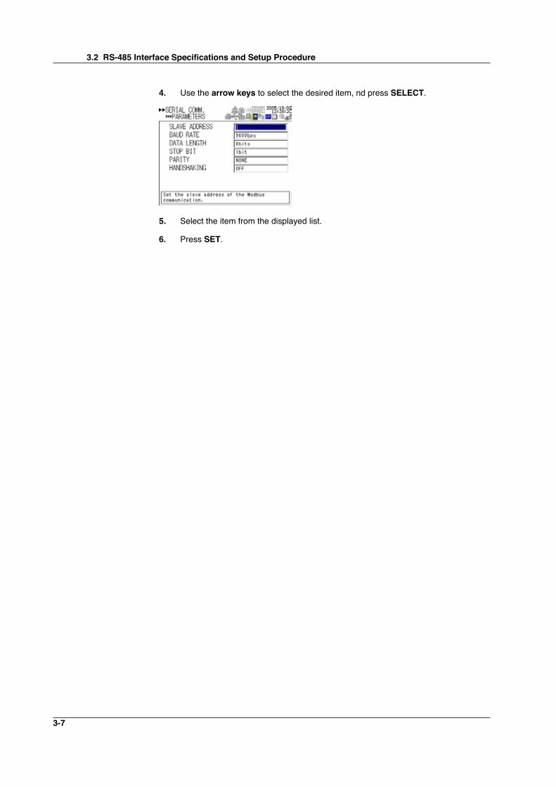
3-7
4. Use the arrow keys to select the desired item, nd press SELECT.
5. Select the item from the displayed list.
6. Press SET.
3.2 RS-485 Interface Specifications and Setup Procedure
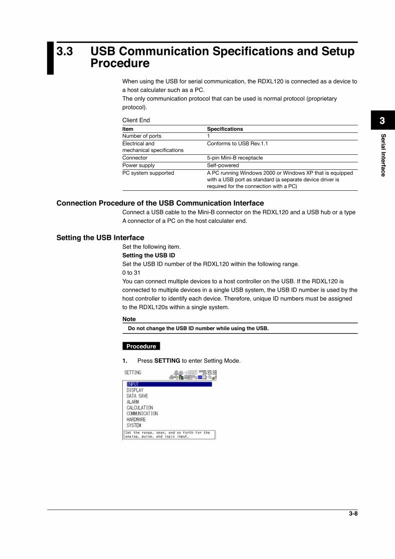
3-8
1
2
3
4
5
6
7
App
Index
Serial Interface
3.3 USB Communication Specifications and Setup Procedure
When using the USB for serial communication, the RDXL120 is connected as a device to a host calculater such as a PC.The only communication protocol that can be used is normal protocol (proprietary protocol).
Client EndItem SpecificationsNumber of ports 1Electrical and Conforms to USB Rev.1.1 mechanical specificationsConnector 5-pin Mini-B receptaclePower supply Self-poweredPC system supported A PC running Windows 2000 or Windows XP that is equipped
with a USB port as standard (a separate device driver is required for the connection with a PC)
Connection Procedure of the USB Communication InterfaceConnect a USB cable to the Mini-B connector on the RDXL120 and a USB hub or a type A connector of a PC on the host calculater end.
Setting the USB InterfaceSet the following item.Setting the USB IDSet the USB ID number of the RDXL120 within the following range.0 to 31You can connect multiple devices to a host controller on the USB. If the RDXL120 is connected to multiple devices in a single USB system, the USB ID number is used by the host controller to identify each device. Therefore, unique ID numbers must be assigned to the RDXL120s within a single system.
Note Do not change the USB ID number while using the USB.
Procedure
1. Press SETTING to enter Setting Mode.
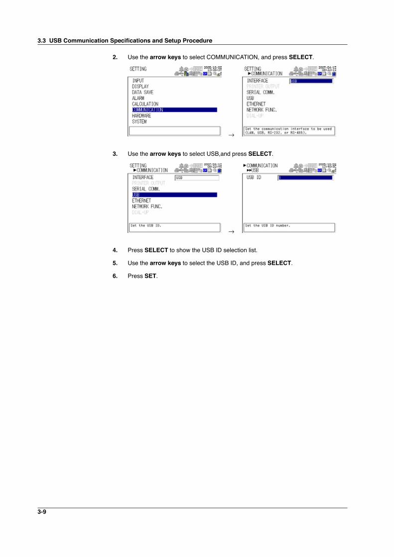
3-9
2. Use the arrow keys to select COMMUNICATION, and press SELECT.
→
3. Use the arrow keys to select USB,and press SELECT.
→
4. Press SELECT to show the USB ID selection list.
5. Use the arrow keys to select the USB ID, and press SELECT.
6. Press SET.
3.3 USB Communication Specifications and Setup Procedure
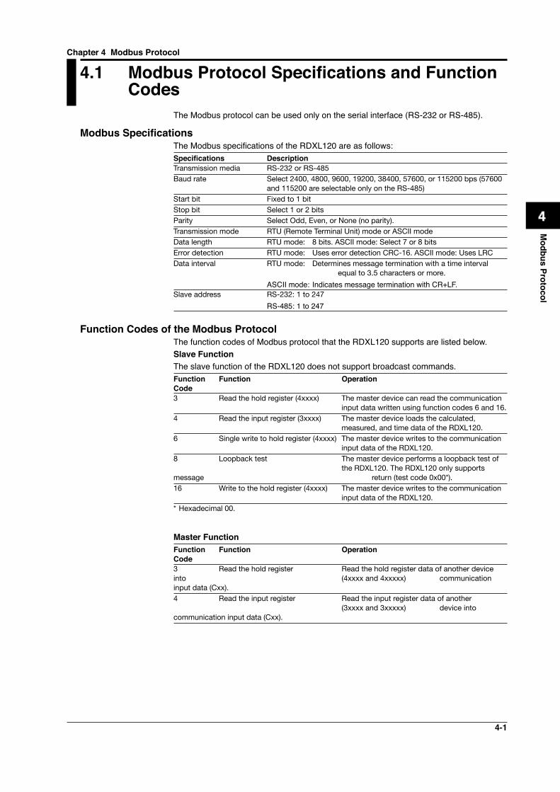
4-1
1
2
3
4
5
6
7
App
Index
Modbus Protocol
4.1 Modbus Protocol Specifications and Function Codes
The Modbus protocol can be used only on the serial interface (RS-232 or RS-485).
Modbus SpecificationsThe Modbus specifications of the RDXL120 are as follows:Specifications DescriptionTransmission media RS-232 or RS-485Baud rate Select 2400, 4800, 9600, 19200, 38400, 57600, or 115200 bps (57600
and 115200 are selectable only on the RS-485)Start bit Fixed to 1 bitStop bit Select 1 or 2 bitsParity Select Odd, Even, or None (no parity).Transmission mode RTU (Remote Terminal Unit) mode or ASCII modeData length RTU mode: 8 bits. ASCII mode: Select 7 or 8 bitsError detection RTU mode: Uses error detection CRC-16. ASCII mode: Uses LRCData interval RTU mode: Determines message termination with a time interval
equal to 3.5 characters or more.
ASCII mode: Indicates message termination with CR+LF.Slave address RS-232: 1 to 247
RS-485: 1 to 247
Function Codes of the Modbus ProtocolThe function codes of Modbus protocol that the RDXL120 supports are listed below.Slave FunctionThe slave function of the RDXL120 does not support broadcast commands.Function Function Operation Code3 Read the hold register (4xxxx) The master device can read the communication input data written using function codes 6 and 16.4 Read the input register (3xxxx) The master device loads the calculated, measured, and time data of the RDXL120.6 Single write to hold register (4xxxx) The master device writes to the communication input data of the RDXL120.8 Loopback test The master device performs a loopback test of the RDXL120. The RDXL120 only supports message return (test code 0x00*).16 Write to the hold register (4xxxx) The master device writes to the communication input data of the RDXL120.* Hexadecimal 00.
Master FunctionFunction Function Operation Code3 Read the hold register Read the hold register data of another device into (4xxxx and 4xxxxx) communication input data (Cxx).4 Read the input register Read the input register data of another (3xxxx and 3xxxxx) device into communication input data (Cxx).
Chapter 4 Modbus Protocol
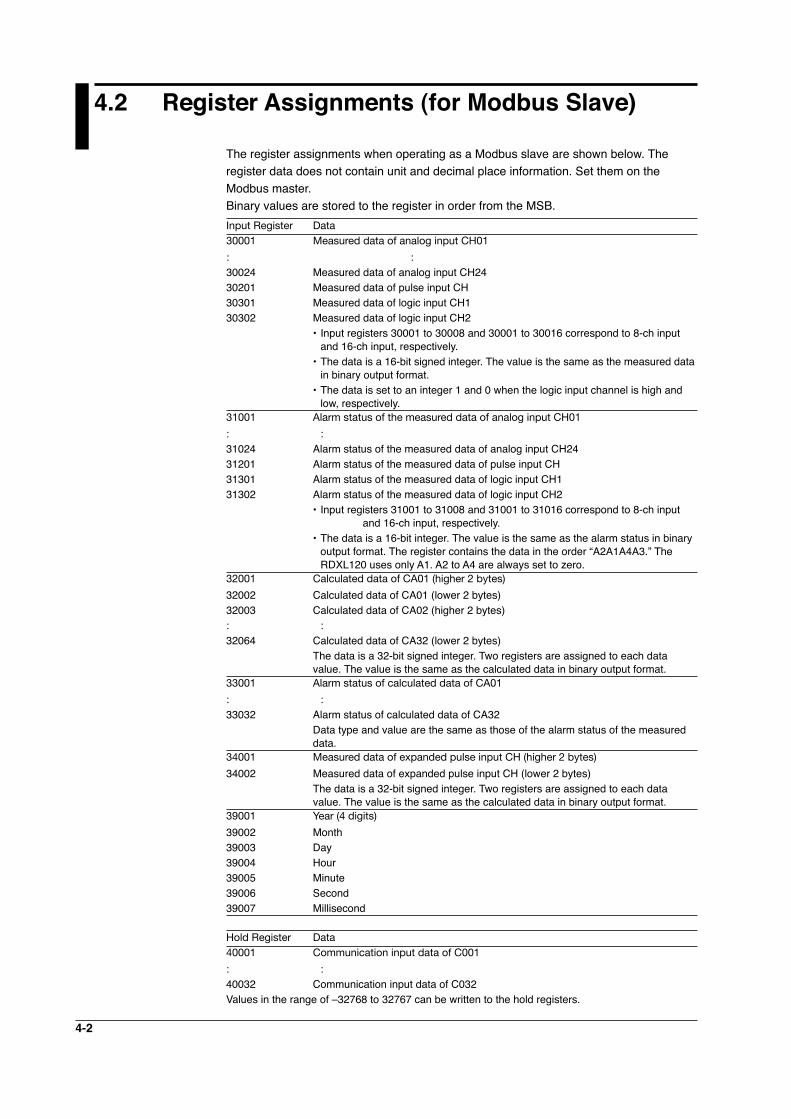
4-2
4.2 Register Assignments (for Modbus Slave)
The register assignments when operating as a Modbus slave are shown below. The register data does not contain unit and decimal place information. Set them on the Modbus master.Binary values are stored to the register in order from the MSB.Input Register Data30001 Measured data of analog input CH01
: :30024 Measured data of analog input CH2430201 Measured data of pulse input CH30301 Measured data of logic input CH130302 Measured data of logic input CH2 • Input registers 30001 to 30008 and 30001 to 30016 correspond to 8-ch input
and 16-ch input, respectively. • The data is a 16-bit signed integer. The value is the same as the measured data
in binary output format. • The data is set to an integer 1 and 0 when the logic input channel is high and
low, respectively.31001 Alarm status of the measured data of analog input CH01
: :31024 Alarm status of the measured data of analog input CH2431201 Alarm status of the measured data of pulse input CH31301 Alarm status of the measured data of logic input CH131302 Alarm status of the measured data of logic input CH2 • Input registers 31001 to 31008 and 31001 to 31016 correspond to 8-ch input
and 16-ch input, respectively. • The data is a 16-bit integer. The value is the same as the alarm status in binary
output format. The register contains the data in the order “A2A1A4A3.” The RDXL120 uses only A1. A2 to A4 are always set to zero.
32001 Calculated data of CA01 (higher 2 bytes)
32002 Calculated data of CA01 (lower 2 bytes)32003 Calculated data of CA02 (higher 2 bytes): :32064 Calculated data of CA32 (lower 2 bytes) The data is a 32-bit signed integer. Two registers are assigned to each data
value. The value is the same as the calculated data in binary output format.33001 Alarm status of calculated data of CA01
: :33032 Alarm status of calculated data of CA32 Data type and value are the same as those of the alarm status of the measured
data.34001 Measured data of expanded pulse input CH (higher 2 bytes)
34002 Measured data of expanded pulse input CH (lower 2 bytes) The data is a 32-bit signed integer. Two registers are assigned to each data
value. The value is the same as the calculated data in binary output format.39001 Year (4 digits)
39002 Month39003 Day39004 Hour39005 Minute39006 Second39007 Millisecond
Hold Register Data40001 Communication input data of C001
: :40032 Communication input data of C032Values in the range of –32768 to 32767 can be written to the hold registers.
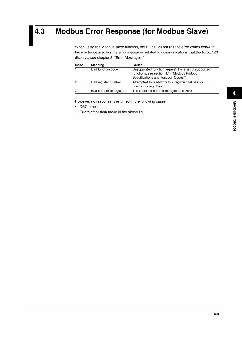
4-3
1
2
3
4
5
6
7
App
Index
Modbus Protocol
4.3 Modbus Error Response (for Modbus Slave)
When using the Modbus slave function, the RDXL120 returns the error codes below to the master device. For the error messages related to communications that the RDXL120 displays, see chapter 8, “Error Messages.”
Code Meaning Cause1 Bad function code Unsupported function request. For a list of supported
functions, see section 4.1, “Modbus Protocol Specifications and Function Codes.”
2 Bad register number Attempted to read/write to a register that has no corresponding channel.
3 Bad number of registers The specified number of registers is zero.
However, no response is returned in the following cases.• CRC error• Errors other than those in the above list.
4-4
4.4 Setting the Modbus Master Function
Set the items below to use the Modbus master function.• Communication Interval The cycle at which data is read from other devices. Select the read cycle from the
following: 100 ms, 200 ms, 500 ms, 1 s, 2 s, 5 s, 10 s, 20 s, 30 s, or 1 min
• Timeout Value Timeout occurs if a response is not received from the specified slave device within the
time specified here (timeout value) after a command is sent from the RDXL120. The RDXL120 repeats the operation of sending a command and waiting for a response for the number of times specified by the retrial value. If no response is received even after waiting the timeout value for all retrials, the RDXL120 stops sending commands to the slave device for a period equal to 10 times the timeout value. Then, the RDXL120 tries again. For details, see section 4.5, “Data Dropout Handling of the Modbus Master.”Select the timeout time from the following:100 ms, 200 ms, 500 ms, 1 s, 2 s, 5 s, 10 s, 20 s, 30 s, or 1 min
• Retrials This is the number of times to retransmit the command when there is no response
from the specified slave device. If no response is received even after retrying the number of times specified here, the RDXL120 stops sending commands to the slave device for a period equal to 10 times the timeout value. Then, the RDXL120 tries again. For details, see section 4.5, “Data Dropout Handling of the Modbus Master.”
Select the number of retrials from the following: OFF (0), 1, 2, 3, 4, 5, 10, or 20
• Commands The commands are used to read the data in the register of slave devices into the
communication input data of the RDXL120 at the read cycle. Consecutive registers of the same data type in a slave device can be registered as a single command and read into consecutive communication input data.• Enabling/Disabling Commands Turn ON the command registration line to be used. Up to 32 commands can be
registered.• Read channel (First CH, Last CH) Set the communication input data (CO01 to CO32) to which the data loaded from
the slave device is to be assigned.• Address Specify the address of the slave device from the following: 1 to 247• Register Specify the register number of the slave device. Since 32-bit data is assigned to
two registers, specify the smaller register number (see “Type” below). Input register: 30001 to 39999, 300001 to 365535 Hold register: 40001 to 49999, 400001 to 465535• Type Specify the data type assigned to the Modbus register of the slave device.
• INT16 Specify this type when a “16-bit signed integer” is assigned to the Modbus
register.
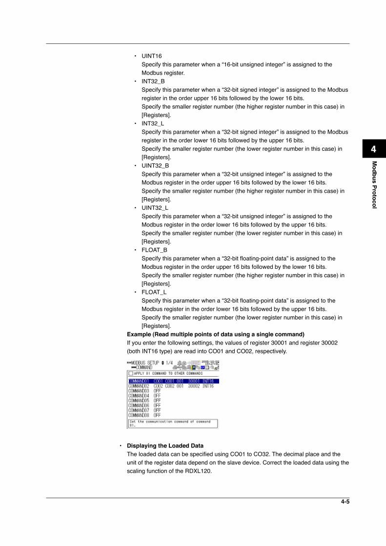
4-5
1
2
3
4
5
6
7
App
Index
Modbus Protocol
• UINT16 Specify this parameter when a “16-bit unsigned integer” is assigned to the
Modbus register.• INT32_B Specify this parameter when a “32-bit signed integer” is assigned to the Modbus
register in the order upper 16 bits followed by the lower 16 bits. Specify the smaller register number (the higher register number in this case) in
[Registers].• INT32_L Specify this parameter when a “32-bit signed integer” is assigned to the Modbus
register in the order lower 16 bits followed by the upper 16 bits. Specify the smaller register number (the lower register number in this case) in
[Registers].• UINT32_B Specify this parameter when a “32-bit unsigned integer” is assigned to the
Modbus register in the order upper 16 bits followed by the lower 16 bits. Specify the smaller register number (the higher register number in this case) in
[Registers].• UINT32_L Specify this parameter when a “32-bit unsigned integer” is assigned to the
Modbus register in the order lower 16 bits followed by the upper 16 bits. Specify the smaller register number (the lower register number in this case) in
[Registers].• FLOAT_B Specify this parameter when a “32-bit floating-point data” is assigned to the
Modbus register in the order upper 16 bits followed by the lower 16 bits. Specify the smaller register number (the higher register number in this case) in
[Registers].• FLOAT_L Specify this parameter when a “32-bit floating-point data” is assigned to the
Modbus register in the order lower 16 bits followed by the upper 16 bits. Specify the smaller register number (the lower register number in this case) in
[Registers]. Example (Read multiple points of data using a single command) If you enter the following settings, the values of register 30001 and register 30002
(both INT16 type) are read into CO01 and CO02, respectively.
• Displaying the Loaded Data The loaded data can be specified using CO01 to CO32. The decimal place and the
unit of the register data depend on the slave device. Correct the loaded data using the scaling function of the RDXL120.
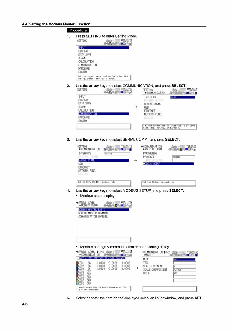
4-6
Procedure
1. Press SETTING to enter Setting Mode.
2. Use the arrow keys to select COMMUNICATION, and press SELECT.
→
3. Use the arrow keys to select SERIAL COMM., and pres SELECT.
→
4. Use the arrow keys to select MODBUS SETUP, and press SELECT. • Modbus setup display
• Modbus settings > communication channel setting diplay
→
5. Select or enter the item on the displayed selection list or window, and press SET.
4.4 Setting the Modbus Master Function
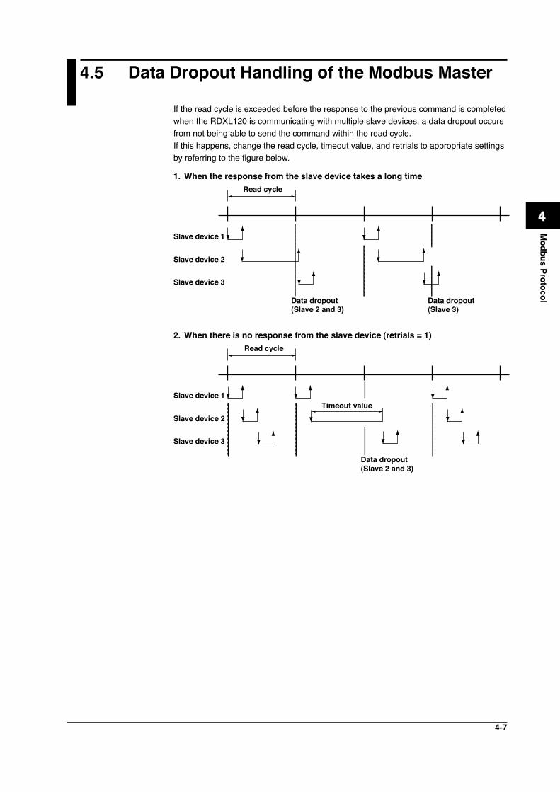
4-7
1
2
3
4
5
6
7
App
Index
Modbus Protocol
4.5 Data Dropout Handling of the Modbus Master
If the read cycle is exceeded before the response to the previous command is completed when the RDXL120 is communicating with multiple slave devices, a data dropout occurs from not being able to send the command within the read cycle.If this happens, change the read cycle, timeout value, and retrials to appropriate settings by referring to the figure below.
1. When the response from the slave device takes a long timeRead cycle
Data dropout(Slave 2 and 3)
Data dropout(Slave 3)
Slave device 1
Slave device 2
Slave device 3
2. When there is no response from the slave device (retrials = 1)Read cycle
Timeout value
Data dropout(Slave 2 and 3)
Slave device 1
Slave device 2
Slave device 3
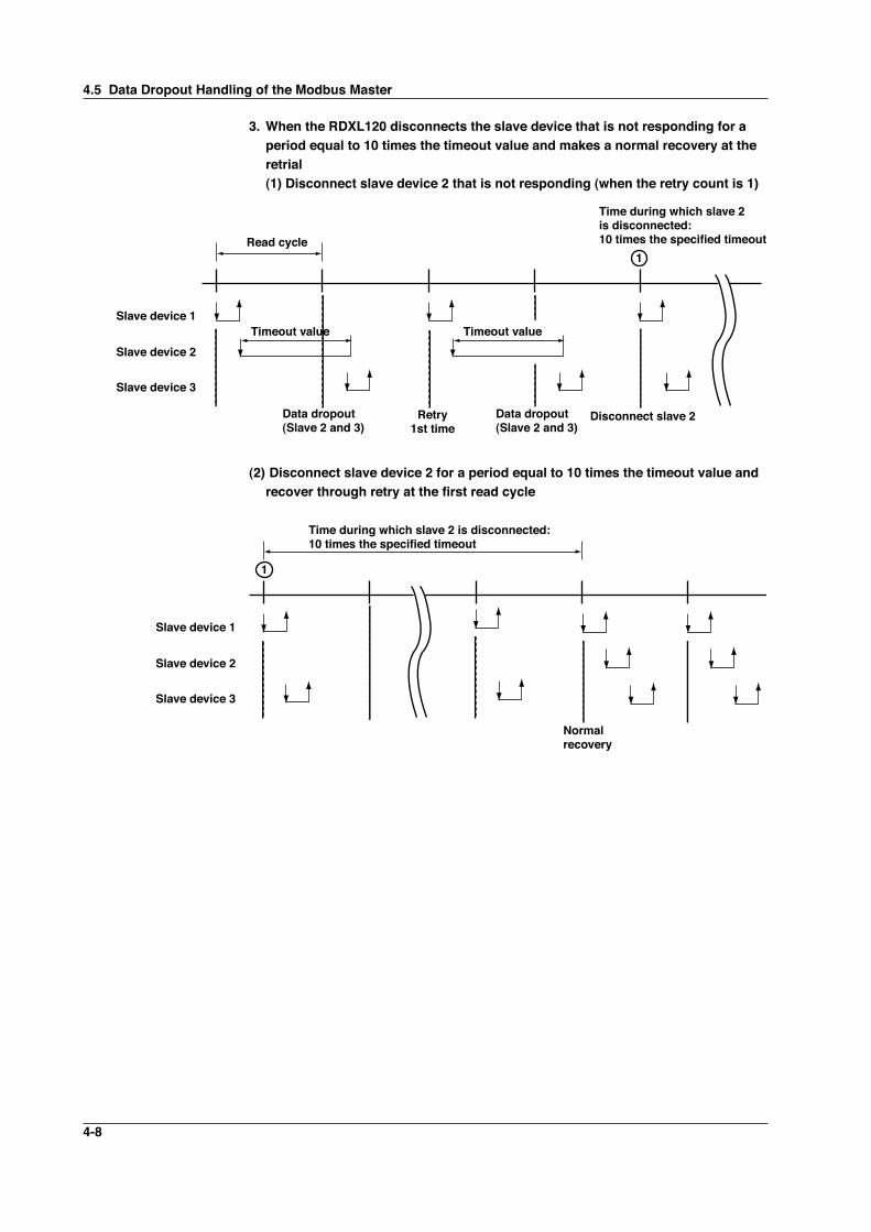
4-8
3. When the RDXL120 disconnects the slave device that is not responding for a period equal to 10 times the timeout value and makes a normal recovery at the retrial (1) Disconnect slave device 2 that is not responding (when the retry count is 1)
Read cycle
Data dropout(Slave 2 and 3)
Data dropout(Slave 2 and 3)
Slave device 1
Slave device 2
Slave device 3
Timeout value Timeout value
Time during which slave 2is disconnected: 10 times the specified timeout
Retry1st time
Disconnect slave 2
1
(2) Disconnect slave device 2 for a period equal to 10 times the timeout value and recover through retry at the first read cycle
Slave device 1
Slave device 2
Slave device 3
Normal recovery
Time during which slave 2 is disconnected: 10 times the specified timeout
1
4.5 Data Dropout Handling of the Modbus Master
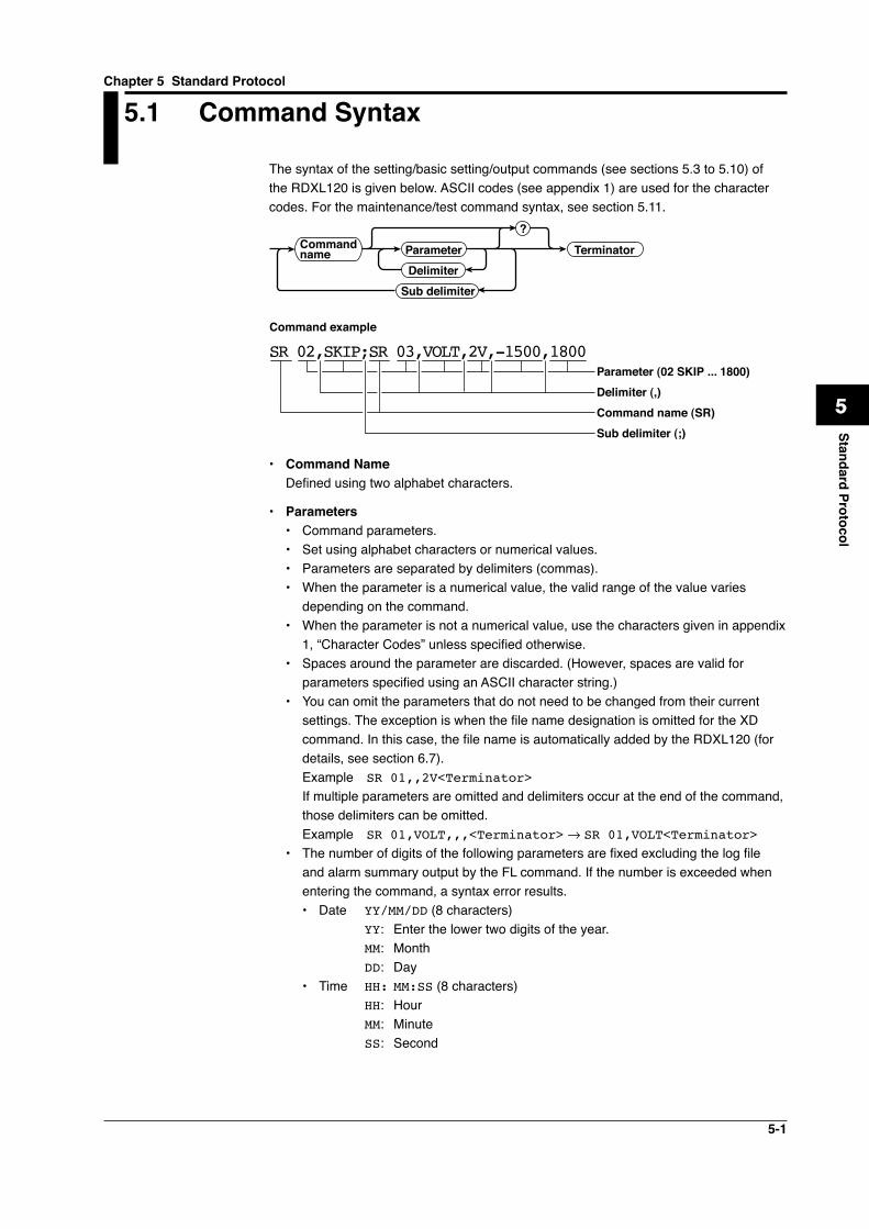
5-1
1
2
3
4
5
6
7
App
Index
Standard Protocol
5.1 Command Syntax
The syntax of the setting/basic setting/output commands (see sections 5.3 to 5.10) of the RDXL120 is given below. ASCII codes (see appendix 1) are used for the character codes. For the maintenance/test command syntax, see section 5.11.
Command name Parameter
?
TerminatorDelimiter
Sub delimiter
SR 02,SKIP;SR 03,VOLT,2V,-1500,1800Parameter (02 SKIP ... 1800)Delimiter (,)Command name (SR)Sub delimiter (;)
Command example
• Command Name Defined using two alphabet characters.
• Parameters• Command parameters.• Set using alphabet characters or numerical values.• Parameters are separated by delimiters (commas).• When the parameter is a numerical value, the valid range of the value varies
depending on the command.• When the parameter is not a numerical value, use the characters given in appendix
1, “Character Codes” unless specified otherwise.• Spaces around the parameter are discarded. (However, spaces are valid for
parameters specified using an ASCII character string.)• You can omit the parameters that do not need to be changed from their current
settings. The exception is when the file name designation is omitted for the XD command. In this case, the file name is automatically added by the RDXL120 (for details, see section 6.7).Example SR 01,,2V<Terminator>
If multiple parameters are omitted and delimiters occur at the end of the command, those delimiters can be omitted.Example SR 01,VOLT,,,<Terminator> → SR 01,VOLT<Terminator>
• The number of digits of the following parameters are fixed excluding the log file and alarm summary output by the FL command. If the number is exceeded when entering the command, a syntax error results.• Date YY/MM/DD (8 characters) YY: Enter the lower two digits of the year. MM: Month DD: Day• Time HH: MM:SS (8 characters) HH: Hour MM: Minute SS: Second
Chapter 5 Standard Protocol
5-2
• Channel number: 2 characters or ‘CH’ + 2 characters for an analog channel ‘PL’ + 2 characters for a pulse channel ‘DI’ + 2 characters for a logic channel ‘CA’ + 2 characters for a calculation channel ‘CO’ + 2 characters for a communication channel
• Alarm output number: 3 characters ‘I’ + 2 characters
• Query• A question mark is used to specify a query.• By placing a query after a command or parameter, the setting information of
the corresponding command can be queried. Some commands cannot execute queries. For the query syntax of each command, see section 5.2.
• Delimiter• A comma is used as a delimiter.• Parameters are separated by delimiters.
• Sub Delimiter• A semicolon is used as a sub delimiter.• By separating each command with a sub delimiter, up to 10 commands can be
specified one after another. However, the commands and queries cannot be specified one after another. Use them independently.* If there are consecutive sub delimiters, they are considered to be single. In addition, sub
delimiters at the front and at the end are ignored.Example ;SR01,VOLT;;;SR02,VOLT;<terminator> is taken to be SR01,VOLT;SR02,V
OLT<terminator>.
• Terminator Use either of the following two characters for the terminator.
• CR+LF (0DH 0AH in ASCII code)• LF (0AH in ASCII code)
Note• Do not specify a channel or alarm output number that is not available on the RDXL120. If
you do, an error will occur.• The total data length from the first character to the terminator must be less than 2047
bytes.• Commands are not case sensitive (with the exception of user-specified character strings).• All the commands that are listed using sub delimiters are executed even if any of the com-
mands in the middle is erroneous.• Spaces that are inserted before and after a parameter are ignored. However, if spaces are
inserted before a command, after a sub delimiter, or after a query, an error occurs.
5.1 Command Syntax
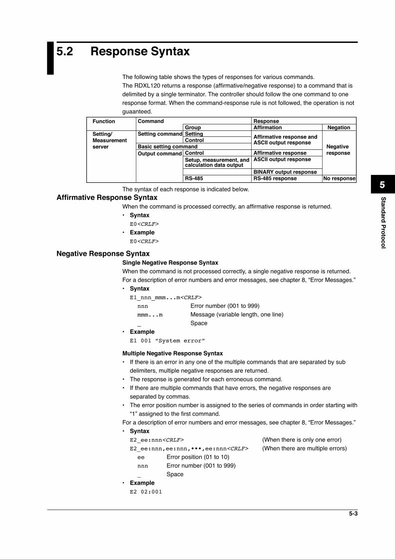
5-3
1
2
3
4
5
6
7
App
Index
Standard Protocol
5.2 Response Syntax
The following table shows the types of responses for various commands.The RDXL120 returns a response (affirmative/negative response) to a command that is delimited by a single terminator. The controller should follow the one command to one response format. When the command-response rule is not followed, the operation is not guaanteed.
Command Response Group Affirmation NegationSetting command Setting Control Affirmative response and
Basic setting command ASCII output response
Negative Output command Control Affirmative response response Setup, measurement, and ASCII output response calculation data output BINARY output response RS-485 RS-485 response No response
Function
Setting/Measurement server
The syntax of each response is indicated below.Affirmative Response Syntax
When the command is processed correctly, an affirmative response is returned.• Syntax E0<CRLF>• Example E0<CRLF>
Negative Response Syntax Single Negative Response SyntaxWhen the command is not processed correctly, a single negative response is returned. For a description of error numbers and error messages, see chapter 8, “Error Messages.”• Syntax E1_nnn_mmm...m<CRLF>
nnn Error number (001 to 999) mmm...m Message (variable length, one line) _ Space
• Example E1 001 “System error”
Multiple Negative Response Syntax• If there is an error in any one of the multiple commands that are separated by sub
delimiters, multiple negative responses are returned.• The response is generated for each erroneous command.• If there are multiple commands that have errors, the negative responses are
separated by commas.• The error position number is assigned to the series of commands in order starting with
“1” assigned to the first command.For a description of error numbers and error messages, see chapter 8, “Error Messages.”• Syntax E2_ee:nnn<CRLF> (When there is only one error) E2_ee:nnn,ee:nnn,•••,ee:nnn<CRLF> (When there are multiple errors)
ee Error position (01 to 10) nnn Error number (001 to 999) _ Space
• Example E2 02:001
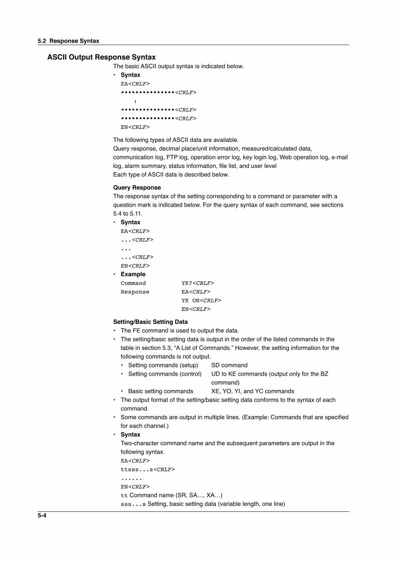
5-4
ASCII Output Response SyntaxThe basic ASCII output syntax is indicated below.• Syntax EA<CRLF> •••••••••••••••<CRLF> : •••••••••••••••<CRLF> •••••••••••••••<CRLF> EN<CRLF>
The following types of ASCII data are available.Query response, decimal place/unit information, measured/calculated data, communication log, FTP log, operation error log, key login log, Web operation log, e-mail log, alarm summary, status information, file list, and user levelEach type of ASCII data is described below.
Query ResponseThe response syntax of the setting corresponding to a command or parameter with a question mark is indicated below. For the query syntax of each command, see sections 5.4 to 5.11.• Syntax EA<CRLF> ...<CRLF> ... ...<CRLF> EN<CRLF>• Example Command YK?<CRLF> Response EA<CRLF> YK ON<CRLF> EN<CRLF>
Setting/Basic Setting Data• The FE command is used to output the data.• The setting/basic setting data is output in the order of the listed commands in the
table in section 5.3, “A List of Commands.” However, the setting information for the following commands is not output.• Setting commands (setup) SD command• Setting commands (control) UD to KE commands (output only for the BZ
command)• Basic setting commands XE, YO, YI, and YC commands
• The output format of the setting/basic setting data conforms to the syntax of each command.
• Some commands are output in multiple lines. (Example: Commands that are specified for each channel.)
• Syntax Two-character command name and the subsequent parameters are output in the
following syntax. EA<CRLF> ttsss...s<CRLF> ...... EN<CRLF> tt Command name (SR, SA…, XA…) sss...s Setting, basic setting data (variable length, one line)
5.2 Response Syntax
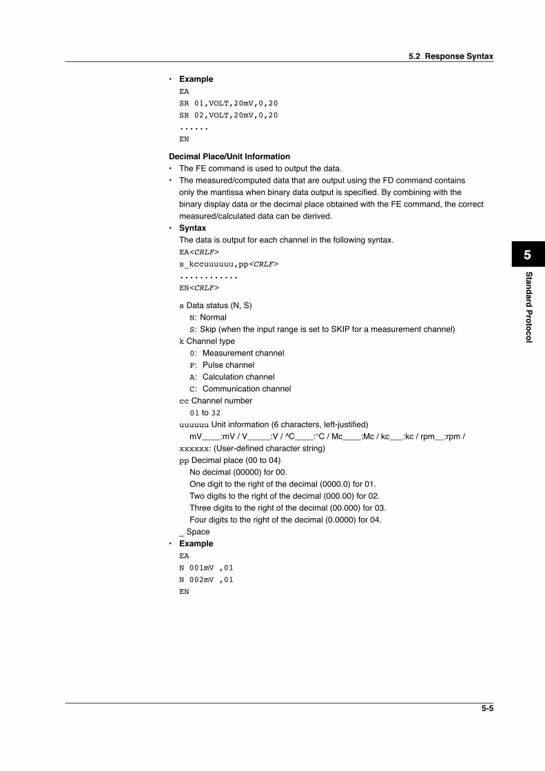
5-5
1
2
3
4
5
6
7
App
Index
Standard Protocol
• Example EA SR 01,VOLT,20mV,0,20 SR 02,VOLT,20mV,0,20 ...... EN
Decimal Place/Unit Information• The FE command is used to output the data.• The measured/computed data that are output using the FD command contains
only the mantissa when binary data output is specified. By combining with the binary display data or the decimal place obtained with the FE command, the correct measured/calculated data can be derived.
• Syntax The data is output for each channel in the following syntax. EA<CRLF> s_kccuuuuuu,pp<CRLF> ............ EN<CRLF>
s Data status (N, S)N: NormalS: Skip (when the input range is set to SKIP for a measurement channel)
k Channel type 0: Measurement channel P: Pulse channel A: Calculation channel C: Communication channelcc Channel number
01 to 32uuuuuu Unit information (6 characters, left-justified) mV____:mV / V_____:V / ^C____:°C / Mc____:Mc / kc___:kc / rpm__:rpm /xxxxxx: (User-defined character string)pp Decimal place (00 to 04)
No decimal (00000) for 00.One digit to the right of the decimal (0000.0) for 01.Two digits to the right of the decimal (000.00) for 02.Three digits to the right of the decimal (00.000) for 03.Four digits to the right of the decimal (0.0000) for 04.
_ Space• Example EA N 001mV ,01 N 002mV ,01 EN
5.2 Response Syntax
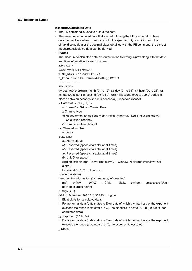
5-6
Measured/Calculated Data• The FD command is used to output the data.• The measured/computed data that are output using the FD command contains
only the mantissa when binary data output is specified. By combining with the binary display data or the decimal place obtained with the FE command, the correct measured/calculated data can be derived.
• Syntax The measured/calculated data are output in the following syntax along with the date
and time information for each channel. EA<CRLF> DATE_yy/mo/dd<CRLF> TIME_hh:mi:ss.mmmt<CRLF> s_kcca1a2a3a4uuuuuufdddddE-pp<CRLF> ............ EN<CRLF> yy year (00 to 99);mo month (01 to 12);dd day (01 to 31);hh hour (00 to 23);mi
minute (00 to 59);ss second (00 to 59);mmm millisecond (000 to 999. A period is placed between seconds and milli-seconds);t reserved (space)s Data status (N, S, O, E)
N: Normal/ S: Skip/O: Over/E: Errork Channel type0: Measurement analog channel/P: Pulse channel/D: Logic input channel/A:
Calculation channel/C: Communication channel
cc Channel number01 to 32
a1a2a3a4 a1 Alarm status a2 Reserved (space character at all times) a3 Reserved (space character at all times) a4 Reserved (space character at all times) (H, L, I, O, or space) (H(High limit alarm)/L(Lower limit alarm)/ I(Window IN alarm)/O(Window OUT
alarm))Reserved (h, l, T, t, R, and r)
Space (no alarm) uuuuuu Unit information (6 characters, left-justified)
mV____:mV/V_____:V/^C____:°C/Mc____:Mc/kc___:kc/rpm__:rpm/xxxxxx: (User-defined character string)
f Sign (+, -) ddddd Mantissa (00000 to 99999, 5 digits)
• Eight digits for calculated data.• For abnormal data (data status is E) or data of which the mantissa or the exponent
exceeds the range (data status is O), the mantissa is set to 99999 (99999999 for calculated data).
pp Exponent (00 to 04)• For abnormal data (data status is E) or data of which the mantissa or the exponent
exceeds the range (data status is O), the exponent is set to 99. _ Space
5.2 Response Syntax
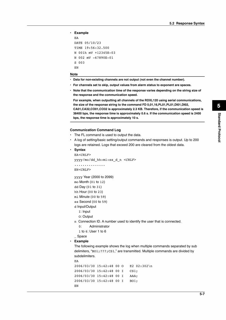
5-7
1
2
3
4
5
6
7
App
Index
Standard Protocol
• Example EA DATE 05/10/23 TIME 19:56:32.500 N 001h mV +12345E-03 N 002 mV -67890E-01 S 003 EN
Note• Data for non-existing channels are not output (not even the channel number).• For channels set to skip, output values from alarm status to exponent are spaces.• Note that the communication time of the response varies depending on the string size of
the response and the communication speed. For example, when outputting all channels of the RDXL120 using serial communications,
the size of the response string to the command FD 0,01,16,PL01,PL01,DI01,DI02, CA01,CA32,CO01,CO32 is approximately 2.3 KB. Therefore, if the communication speed is 38400 bps, the response time is approximately 0.6 s. If the communication speed is 2400 bps, the response time is approximately 10 s.
Communication Command Log• The FL command is used to output the data.• A log of setting/basic setting/output commands and responses is output. Up to 200
logs are retained. Logs that exceed 200 are cleared from the oldest data.• Syntax EA<CRLF> yyyy/mo/dd_hh:mi:ss_d_n <CRLF> ............... EN<CRLF>
yyyy Year (2000 to 2099) mo Month (01 to 12) dd Day (01 to 31) hh Hour (00 to 23) mi Minute (00 to 59) ss Second (00 to 59) d Input/Output
I: Input O: Output
n Connection ID. A number used to identify the user that is connected. 0: Administrator 1 to 6: User 1 to 6
_ Space• Example The following example shows the log when multiple commands separated by sub
delimiters, “BO1;???;CS1,” are transmitted. Multiple commands are divided by subdelimiters.
EA 2006/03/30 15:42:48 00 O E2 02:302\n 2006/03/30 15:42:48 00 I CS1; 2006/03/30 15:42:48 00 I AAA; 2006/03/30 15:42:48 00 I BO1; EN
5.2 Response Syntax
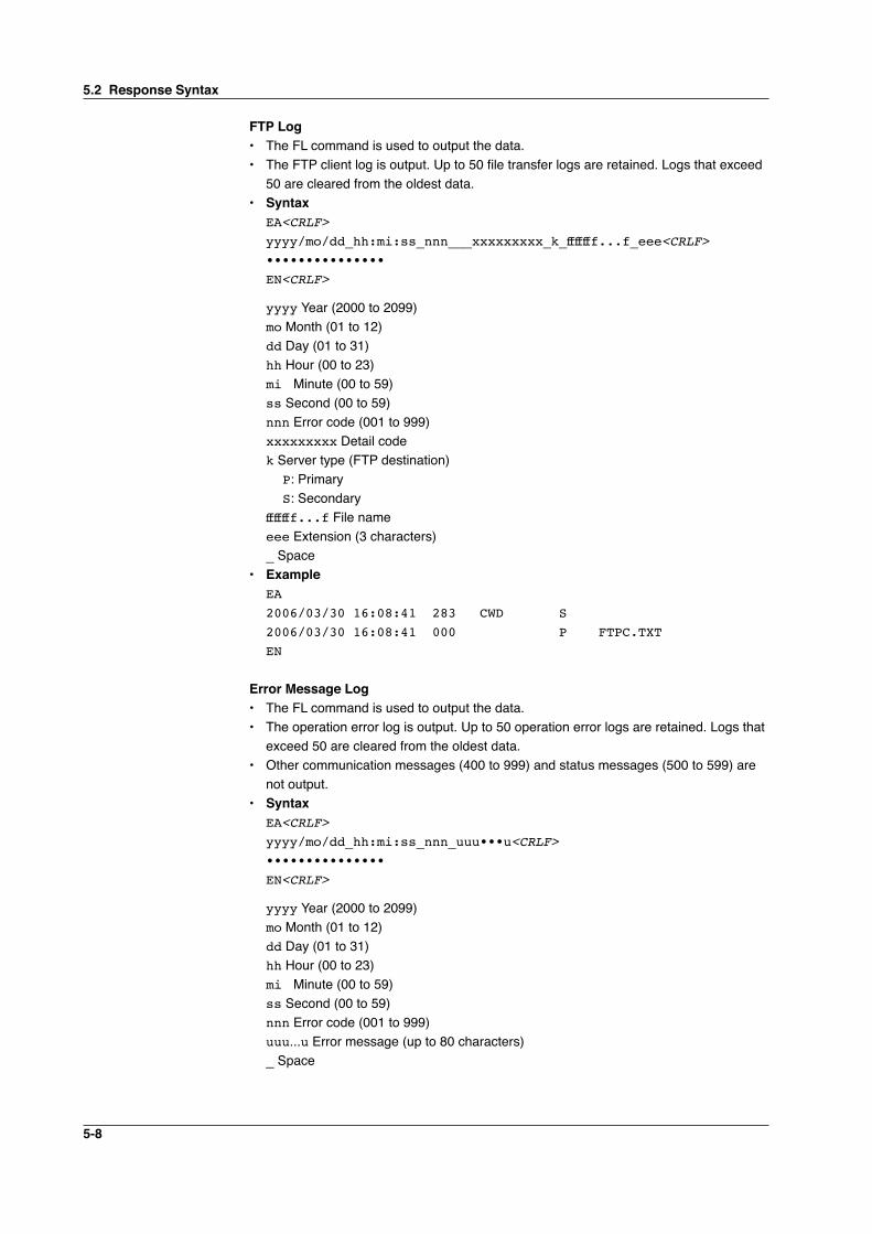
5-8
FTP Log• The FL command is used to output the data.• The FTP client log is output. Up to 50 file transfer logs are retained. Logs that exceed
50 are cleared from the oldest data.• Syntax EA<CRLF> yyyy/mo/dd_hh:mi:ss_nnn___xxxxxxxxx_k_fffffff...f_eee<CRLF> ••••••••••••••• EN<CRLF>
yyyy Year (2000 to 2099) mo Month (01 to 12) dd Day (01 to 31) hh Hour (00 to 23) mi Minute (00 to 59) ss Second (00 to 59) nnn Error code (001 to 999) xxxxxxxxx Detail code k Server type (FTP destination)
P: Primary S: Secondary
fffffff...f File name eee Extension (3 characters) _ Space• Example EA 2006/03/30 16:08:41 283 CWD S 2006/03/30 16:08:41 000 P FTPC.TXT EN Error Message Log• The FL command is used to output the data.• The operation error log is output. Up to 50 operation error logs are retained. Logs that
exceed 50 are cleared from the oldest data.• Other communication messages (400 to 999) and status messages (500 to 599) are
not output.• Syntax EA<CRLF> yyyy/mo/dd_hh:mi:ss_nnn_uuu•••u<CRLF> ••••••••••••••• EN<CRLF>
yyyy Year (2000 to 2099) mo Month (01 to 12) dd Day (01 to 31) hh Hour (00 to 23) mi Minute (00 to 59) ss Second (00 to 59) nnn Error code (001 to 999) uuu...u Error message (up to 80 characters) _ Space
5.2 Response Syntax
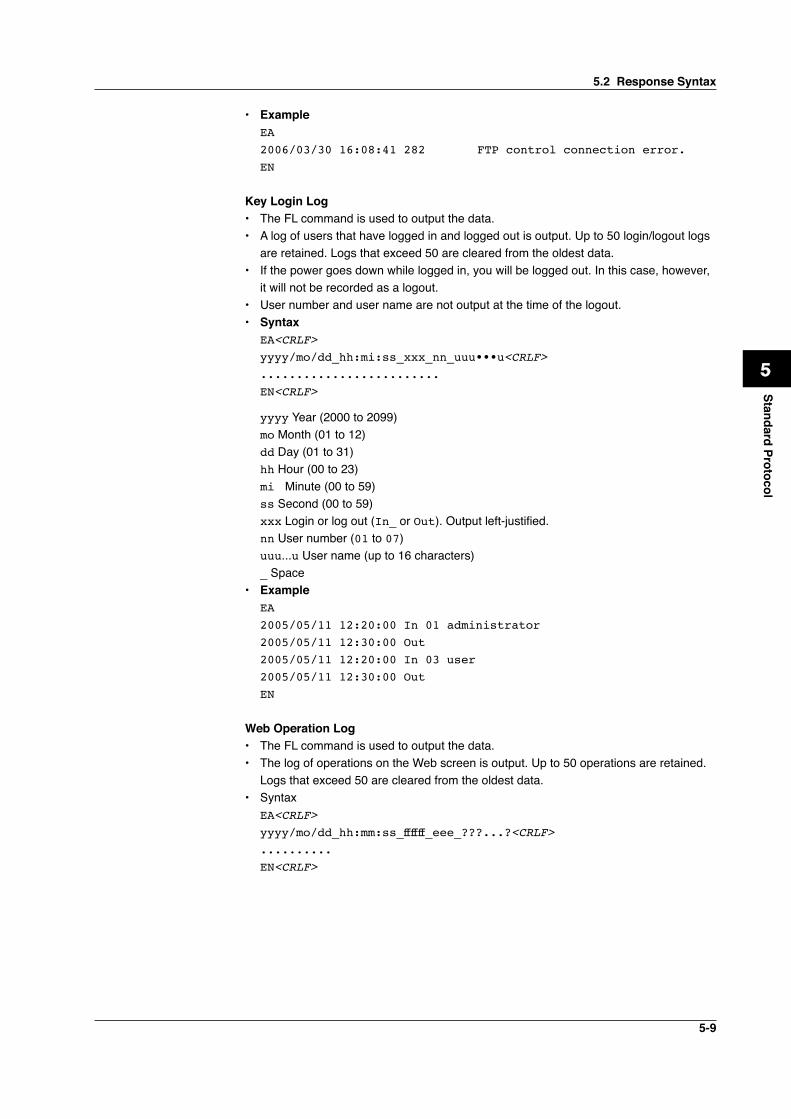
5-9
1
2
3
4
5
6
7
App
Index
Standard Protocol
• Example EA 2006/03/30 16:08:41 282 FTP control connection error. EN Key Login Log• The FL command is used to output the data.• A log of users that have logged in and logged out is output. Up to 50 login/logout logs
are retained. Logs that exceed 50 are cleared from the oldest data.• If the power goes down while logged in, you will be logged out. In this case, however,
it will not be recorded as a logout.• User number and user name are not output at the time of the logout.• Syntax EA<CRLF> yyyy/mo/dd_hh:mi:ss_xxx_nn_uuu•••u<CRLF> ......................... EN<CRLF>
yyyy Year (2000 to 2099) mo Month (01 to 12) dd Day (01 to 31) hh Hour (00 to 23) mi Minute (00 to 59) ss Second (00 to 59) xxx Login or log out (In_ or Out). Output left-justified. nn User number (01 to 07) uuu...u User name (up to 16 characters) _ Space• Example EA 2005/05/11 12:20:00 In 01 administrator 2005/05/11 12:30:00 Out 2005/05/11 12:20:00 In 03 user 2005/05/11 12:30:00 Out EN Web Operation Log• The FL command is used to output the data.• The log of operations on the Web screen is output. Up to 50 operations are retained. Logs that exceed 50 are cleared from the oldest data.• Syntax EA<CRLF> yyyy/mo/dd_hh:mm:ss_ffffff_eee_???...?<CRLF> .......... EN<CRLF>
5.2 Response Syntax
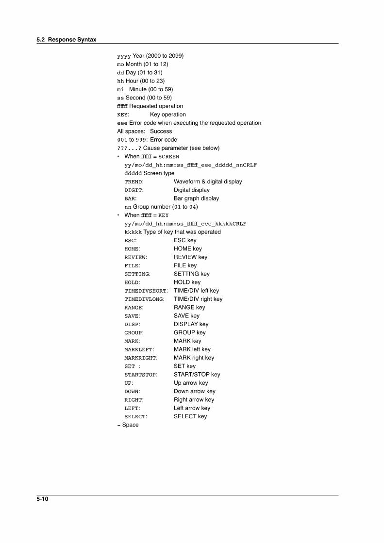
5-10
yyyy Year (2000 to 2099) mo Month (01 to 12) dd Day (01 to 31) hh Hour (00 to 23) mi Minute (00 to 59) ss Second (00 to 59) ffffff Requested operation KEY: Key operation eee Error code when executing the requested operation All spaces: Success 001 to 999: Error code ???...? Cause parameter (see below)
• When ffffff = SCREENyy/mo/dd_hh:mm:ss_ffffff_eee_ddddd_nnCRLFddddd Screen typeTREND: Waveform & digital displayDIGIT: Digital displayBAR: Bar graph displaynn Group number (01 to 04)
• When ffffff = KEYyy/mo/dd_hh:mm:ss_ffffff_eee_kkkkkCRLFkkkkk Type of key that was operatedESC: ESC keyHOME: HOME keyREVIEW: REVIEW keyFILE: FILE keySETTING: SETTING keyHOLD: HOLD keyTIMEDIVSHORT: TIME/DIV left keyTIMEDIVLONG: TIME/DIV right keyRANGE: RANGE keySAVE: SAVE keyDISP: DISPLAY keyGROUP: GROUP keyMARK: MARK keyMARKLEFT: MARK left key MARKRIGHT: MARK right keySET : SET keySTARTSTOP: START/STOP keyUP: Up arrow key DOWN: Down arrow keyRIGHT: Right arrow keyLEFT: Left arrow keySELECT: SELECT key
- Space
5.2 Response Syntax
5-11
1
2
3
4
5
6
7
App
Index
Standard Protocol
• Example EA 2001/02/11 12:30:00 KEYUP 2001/02/11 12:31:00 KEYRIGHT EN E-mail Log• The FL command is used to output the data.• The e-mail transmission log is output. Up to 50 operations are retained. Logs that
exceed 50 are cleared from the oldest data.• Syntax EA<CRLF> yyyy/mo/dd_hh:mm:ss_ffffff_eee_n_uuu...u<CRLF> .......... EN<CRLF>
yyyy Year (2000 to 2099) mo Month (01 to 12) dd Day (01 to 31) hh Hour (00 to 23) mi Minute (00 to 59) ss Second (00 to 59) ffffff Factor
ALM: Alarm mailTIME: Scheduled mailSYS: System error mail
eee Error codeAll spaces: Success001 to 999: Error code
n Recipient list 1: List 1 2: List 2 1-2: List 1 and list 2
uuu...u Array of recipient e-mail addresses (up to 30 characters) _ Space• Example EA 2006/03/30 18:55:27 Test EN
5.2 Response Syntax
5-12
• Syntax EA<CRLF> kkkk__c__sssss_mo/dd_hh:mm:ss.zzz__MO/DD_HH:MM:SS.ZZZ<CRLF> ............... EN<CRLF>
kkkk Channel type CHxx: Analog measurement channel (8 ch terminal block xx: 01 to 08, 16 ch
terminal block xx: 01 to 16) PLS: Pulse measurement channel Lxx: Logic measurement channel (xx: 01 or 02) CAxx: Calculation channel (xx: 01 to 32) COxx: Communication channel (xx: 01 to 32)
c Alarm output channel (none, 1 to 4) sssss Alarm type (H, L, IN, OUT, PH, PL, PWIN, PWOUT, LH, LL) mo Alarm start month (01 to 12) dd Alarm start day (01 to 31) hh Alarm start hour (00 to 23) mm Alarm start minute (00 to 59) ss Alarm start second (00 to 59) zzz Alarm start ms (000 to 999) MO Alarm end month (none, 01 to 12) DD Alarm end day (none, 01 to 31) HH Alarm end hour (none, 00 to 23) MM Alarm end minute (none, 00 to 59) SS Alarm end second (none, 00 to 59) ZZZ Alarm end ms (none, 000 to 999) _ Space• Example EA CH08 1 L 12/22 21:13:00.105 L02 LH 12/22 15:43:43.104 L01 LH 12/22 15:43:43.104 EN
Status Information• The IS command is used to output the data.• The operation status of the RDXL120 is output.• For details on the status information, see section 6.2, “Bit Structure of the Status
Information.”• Syntax EA<CRLF> ddd.ccc.bbb.aaa<CRLF> EN<CRLF>
aaa Status information 1 (000 to 255) bbb Status information 2 (000 to 255) ccc Status information 3 (000 to 255) ddd Status information 4 (000 to 255)
5.2 Response Syntax
5-13
1
2
3
4
5
6
7
App
Index
Standard Protocol
• Example EA 000.000.032.000 EN File List• The ME command is used to output the data.• The file list and the file data sizes of the specified directory on the RDXL120’s external
storage medium are output.• Syntax EA<CRLF> ffffffff_eee_ssssssss_yy/mo/dd_hh:mi:ss ................. zzzzzzz Kbyte free<CRLF> EN<CRLF>
ffffffff File name (Up to 150 characters) eee Extension (3 characters) ssssssss Data size of the file (_______0 to 99999999) [byte(s)] yy Year (00 to 99) mo Month (01 to 12) dd Day (01 to 31) hh Hour (00 to 23) mi Minute (00 to 59) ss Second (00 to 59) zzzzzzz Free space on the medium (______0 to 9999999) _ Space• Example EA BACKUP.SET 15344 05/12/22 11:16:04 051220095255.DLO 14565 05/12/22 11:27:00 ATESTFTP.CSV 11877 05/12/23 15:20:42 ATESTFTPR001.CSV 14203 05/12/23 15:23:08 DATA0 <DIR> 05/12/22 11:12:10 051222210545.BMP 230454 05/12/22 21:05:46 051222210547.ALM 7431 05/12/22 21:05:46 123122 KByte free EN
5.2 Response Syntax
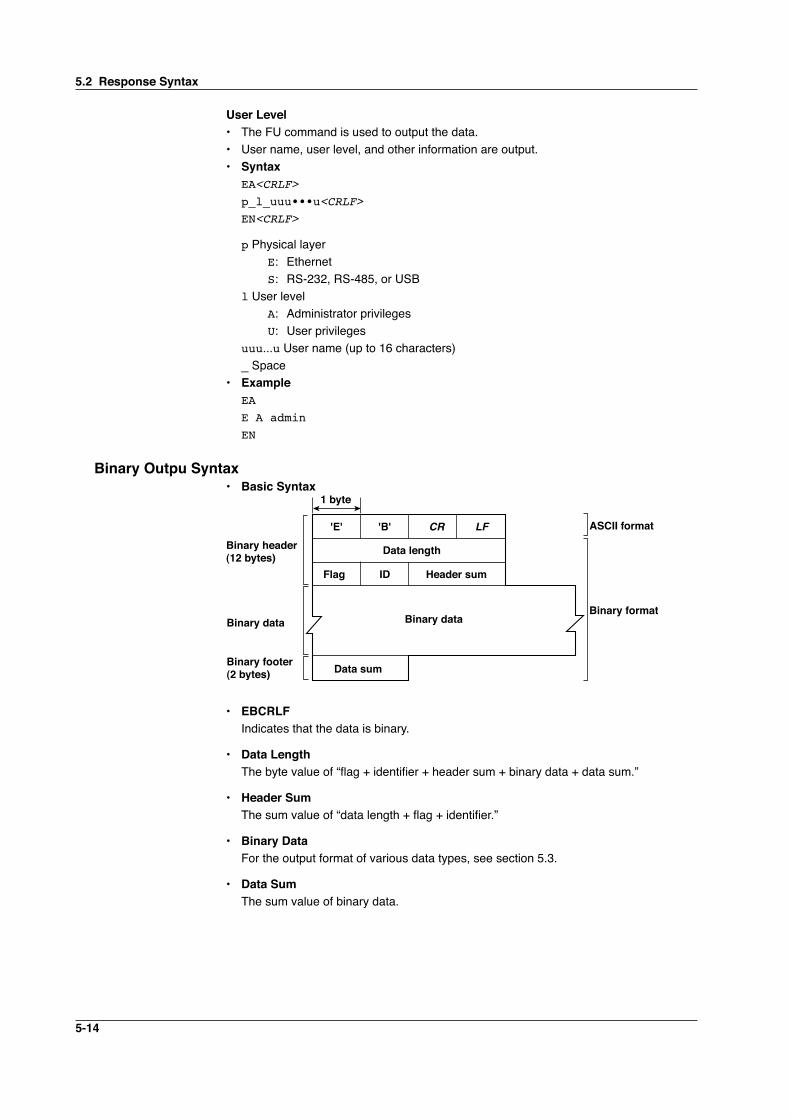
5-14
User Level• The FU command is used to output the data.• User name, user level, and other information are output.• Syntax EA<CRLF> p_l_uuu•••u<CRLF> EN<CRLF>
p Physical layer E: Ethernet S: RS-232, RS-485, or USB l User level A: Administrator privileges U: User privileges uuu...u User name (up to 16 characters) _ Space• Example EA E A admin EN
Binary Outpu Syntax• Basic Syntax
'E' 'B' CR LF
Binary data
ASCII format
Binary format
Data length
Data sum
Flag ID Header sum
1 byte
Binary header(12 bytes)
Binary data
Binary footer(2 bytes)
• EBCRLF Indicates that the data is binary.
• Data Length The byte value of “flag + identifier + header sum + binary data + data sum.”
• Header Sum The sum value of “data length + flag + identifier.”
• Binary DataFor the output format of various data types, see section 5.3.
• Data Sum The sum value of binary data.
5.2 Response Syntax
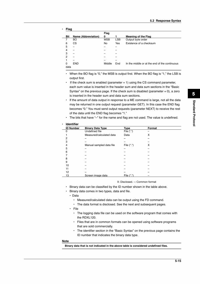
5-15
1
2
3
4
5
6
7
App
Index
Standard Protocol
• Flag FlagBit Name (Abbreviation) 0 1 Meaning of the Flag7 BO MSB LSB Output byte order6 CS No Yes Existence of a checksum5 – – –4 – – –3 – – –2 – – –1 – – –0 END Middle End In the middle or at the end of the continuous data
• When the BO flag is “0,” the MSB is output first. When the BO flag is “1,” the LSB is output first.
• If the check sum is enabled (parameter = 1) using the CS command parameter, each sum value is inserted in the header sum and data sum sections in the “Basic Syntax” on the previous page. If the check sum is disabled (parameter = 0), a zero is inserted in the header sum and data sum sections.
• If the amount of data output in response to a ME command is large, not all the data may be returned in one output request (parameter GET). In this case the END flag becomes “0.” You must send output requests (parameter NEXT) to receive the rest of the data until the END flag becomes “1.”
• The bits that have “–” for the name and flag are not used. The value is undefined.
• IdentifierID Number Binary Data Type Type Format0 Undefined file File (*.*) –1 Measured/calculated data Data X2 – – –3 – – –4 Manual sampled data file File (*.*) X5 – – –6 – – –7 – – –8 – – –9 – – –10 – – –11 – – –12 – – –13 Screen image data File (*.*) –
X: Disclosed. –: Common format
• Binary data can be classified by the ID number shown in the table above.• Binary data comes in two types, data and file. • Data
• Measured/calculated data can be output using the FD command.• The data format is disclosed. See the next and subsequent pages.
• File• The logging data file can be used on the software program that comes with
the RDXL120.• Files that are in common formats can be opened using software programs
that are sold commercially.• The identifier section in the “Basic Syntax” on the previous page contains the
ID number that indicates the binary data type.
Note Binary data that is not indicated in the above table is considered undefined files.
5.2 Response Syntax
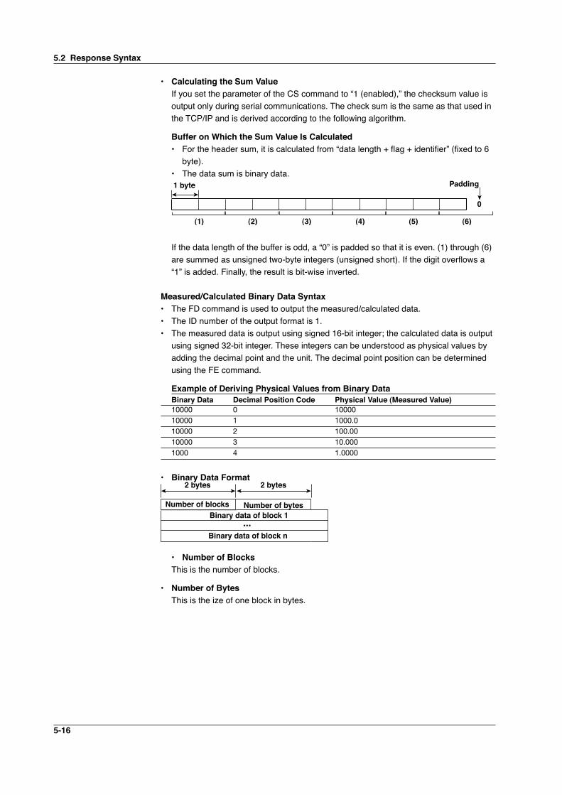
5-16
• Calculating the Sum Value If you set the parameter of the CS command to “1 (enabled),” the checksum value is
output only during serial communications. The check sum is the same as that used in the TCP/IP and is derived according to the following algorithm.
Buffer on Which the Sum Value Is Calculated• For the header sum, it is calculated from “data length + flag + identifier” (fixed to 6
byte).• The data sum is binary data.1 byte
0
(1) (2) (3) (4) (6)(5)
Padding
If the data length of the buffer is odd, a “0” is padded so that it is even. (1) through (6)
are summed as unsigned two-byte integers (unsigned short). If the digit overflows a “1” is added. Finally, the result is bit-wise inverted.
Measured/Calculated Binary Data Syntax• The FD command is used to output the measured/calculated data.• The ID number of the output format is 1.• The measured data is output using signed 16-bit integer; the calculated data is output
using signed 32-bit integer. These integers can be understood as physical values by adding the decimal point and the unit. The decimal point position can be determined using the FE command.
Example of Deriving Physical Values from Binary DataBinary Data Decimal Position Code Physical Value (Measured Value)10000 0 1000010000 1 1000.010000 2 100.0010000 3 10.0001000 4 1.0000
• Binary Data Format
Number of bytes
2 bytes
Number of blocks
•••Binary data of block n
2 bytes
Binary data of block 1
• Number of Blocks This is the number of blocks.
• Number of Bytes This is the ize of one block in bytes.
5.2 Response Syntax
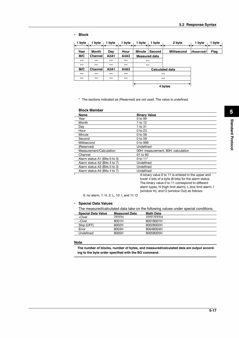
5-17
1
2
3
4
5
6
7
App
Index
Standard Protocol
• Block
YearM/C••••••
M/C••••••
MonthChannel
••••••
Channel••••••
DayA2A1
••••••
A2A1••••••
HourA4A3
••••••
A4A3••••••
Minute Millisecond (Reserved)* FlagSecondMeasured data
••••••
Calculated data••••••
1 byte 1 byte 1 byte 1 byte 1 byte 1 byte 2 byte 1 byte 1 byte
4 bytes
* The sections indicated as (Reserved) are not used. The value is undefined.
Block MemberName Binary ValueYear 0 to 99Month 1 to 12Day 1 to 31Hour 0 to 23Minute 0 to 59Second 0 to 59Millisecond 0 to 999(Reserved) UndefinedMeasurement/Calculation 00H: measurement, 80H: calculationChannel 01 to 60Alarm status A1 (Bits 0 to 3) 0 to 11*Alarm status A2 (Bits 4 to 7) UndefinedAlarm status A3 (Bits 0 to 3) UndefinedAlarm status A4 (Bits 4 to 7) Undefined
* A binary value 0 to 11 is entered in the upper and lower 4 bits of a byte (8 bits) for the alarm status. The binary value 0 to 11 correspond to different alarm types, H (high limit alarm), L (low limit alarm, I (window In), and O (window Out) as follows:
0: no alarm, 1: H, 2: L, 10: I, and 11: O
• Special Data Values The measured/calculated data take on the following values under special conditions.
Special Data Value Measured Data Math Data+Over 7FFFH 7FFF7FFFH–Over 8001H 80018001HSkip (OFF) 8002H 80028002HError 8004H 80048004HUndefined 8005H 80058005H
Note The number of blocks, number of bytes, and measured/calculated data are output accord-
ing to the byte order specified with the BO command.
5.2 Response Syntax
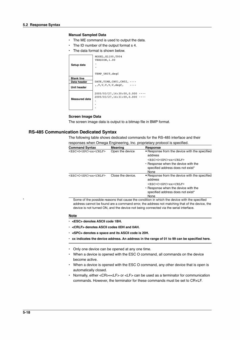
5-18
Manual Sampled Data• The ME command is used to output the data.• The ID number of the output format s 4.• The data format is shown below.
MODEL,XL100,T004VERSION,1.00..
TEMP_UNIT,degC
Setup data
Blank lineData header
Unit header
Measured data
DATE,TIME,CH01,CH02,,,V,V,V,V,V,degC,
....
....
2005/03/27,14:30:00,0.0002005/03/27,14:31:00,0.000...
....
....
Screen Image DataThe screen image data is output to a bitmap file in BMP format.
RS-485 Communication Dedicated SyntaxThe following table shows dedicated commands for the RS-485 interface and their responses when Omega Engineering, Inc. proprietary protocol is specified.Command Syntax Meaning Response<ESC>O<SPC>xx<CRLF> Open the device • Response from the device with the specified
address <ESC>O<SPC>xx<CRLF> • Response when the device with the
specified address does not exist* None<ESC>C<SPC>xx<CRLF> Close the device. • Response from the device with the specified
address <ESC>C<SPC>xx<CRLF> • Response when the device with the
specified address does not exist* None
* Some of the possible reasons that cause the condition in which the device with the specified address cannot be found are a command error, the address not matching that of the device, the device is not turned ON, and the device not being connected via the serial interface.
Note• <ESC> denotes ASCII code 1BH.• <CRLF> denotes ASCII codes 0DH and 0AH.• <SPC> denotes a space and its ASCII code is 20H.• xx indicates the device address. An address in the range of 01 to 99 can be specified here.
• Only one device can be opened at any one time.• When a device is opened with the ESC O command, all commands on the device
become active.• When a device is opened with the ESC O command, any other device that is open is
automatically closed.• Normally, either <CR>+<LF> or <LF> can be used as a terminator for communication
commands. However, the terminator for these commands must be set to CR+LF.
5.2 Response Syntax
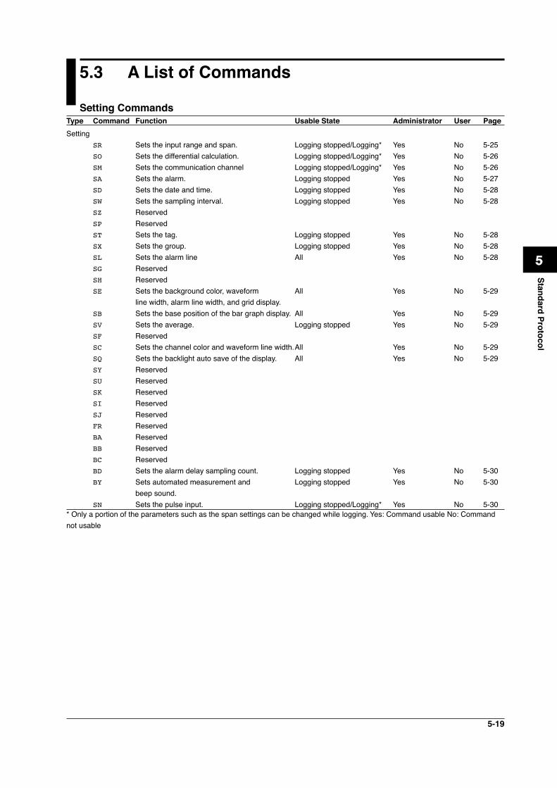
5-19
1
2
3
4
5
6
7
App
Index
Standard Protocol
5.3 A List of Commands
Setting CommandsType Command Function Usable State Administrator User PageSetting SR Sets the input range and span. Logging stopped/Logging* Yes No 5-25 SO Sets the differential calculation. Logging stopped/Logging* Yes No 5-26 SM Sets the communication channel Logging stopped/Logging* Yes No 5-26 SA Sets the alarm. Logging stopped Yes No 5-27 SD Sets the date and time. Logging stopped Yes No 5-28 SW Sets the sampling interval. Logging stopped Yes No 5-28 SZ Reserved SP Reserved ST Sets the tag. Logging stopped Yes No 5-28 SX Sets the group. Logging stopped Yes No 5-28 SL Sets the alarm line All Yes No 5-28 SG Reserved SH Reserved SE Sets the background color, waveform All Yes No 5-29 line width, alarm line width, and grid display. SB Sets the base position of the bar graph display. All Yes No 5-29 SV Sets the average. Logging stopped Yes No 5-29 SF Reserved SC Sets the channel color and waveform line width. All Yes No 5-29 SQ Sets the backlight auto save of the display. All Yes No 5-29 SY Reserved SU Reserved SK Reserved SI Reserved SJ Reserved FR Reserved BA Reserved BB Reserved BC Reserved BD Sets the alarm delay sampling count. Logging stopped Yes No 5-30 BY Sets automated measurement and Logging stopped Yes No 5-30 beep sound. SN Sets the pulse input. Logging stopped/Logging* Yes No 5-30* Only a portion of the parameters such as the span settings can be changed while logging. Yes: Command usable No: Command not usable
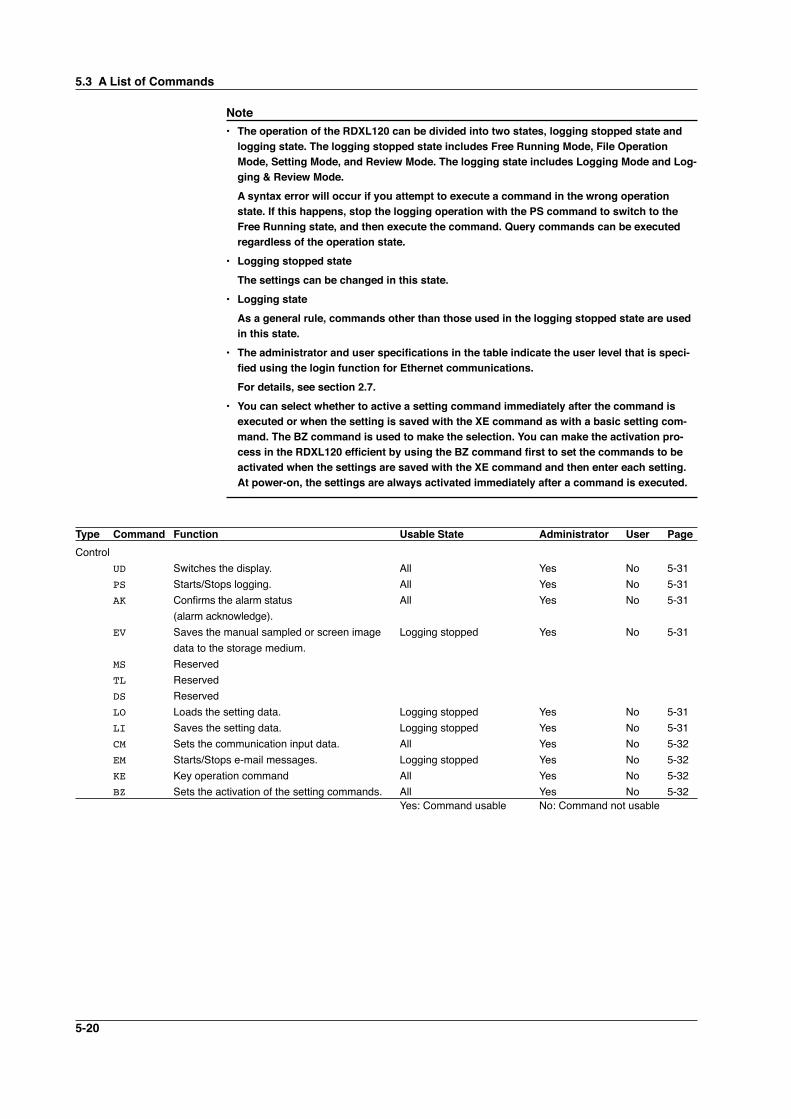
5-20
Note• The operation of the RDXL120 can be divided into two states, logging stopped state and
logging state. The logging stopped state includes Free Running Mode, File Operation Mode, Setting Mode, and Review Mode. The logging state includes Logging Mode and Log-ging & Review Mode.
A syntax error will occur if you attempt to execute a command in the wrong operation state. If this happens, stop the logging operation with the PS command to switch to the Free Running state, and then execute the command. Query commands can be executed regardless of the operation state.
• Logging stopped state The settings can be changed in this state.• Logging state As a general rule, commands other than those used in the logging stopped state are used
in this state.• The administrator and user specifications in the table indicate the user level that is speci-
fied using the login function for Ethernet communications. For details, see section 2.7.• You can select whether to active a setting command immediately after the command is
executed or when the setting is saved with the XE command as with a basic setting com-mand. The BZ command is used to make the selection. You can make the activation pro-cess in the RDXL120 efficient by using the BZ command first to set the commands to be activated when the settings are saved with the XE command and then enter each setting. At power-on, the settings are always activated immediately after a command is executed.
Type Command Function Usable State Administrator User PageControl UD Switches the display. All Yes No 5-31 PS Starts/Stops logging. All Yes No 5-31 AK Confirms the alarm status All Yes No 5-31 (alarm acknowledge). EV Saves the manual sampled or screen image Logging stopped Yes No 5-31 data to the storage medium. MS Reserved TL Reserved DS Reserved LO Loads the setting data. Logging stopped Yes No 5-31 LI Saves the setting data. Logging stopped Yes No 5-31 CM Sets the communication input data. All Yes No 5-32 EM Starts/Stops e-mail messages. Logging stopped Yes No 5-32 KE Key operation command All Yes No 5-32 BZ Sets the activation of the setting commands. All Yes No 5-32 Yes: Command usable No: Command not usable
5.3 A List of Commands
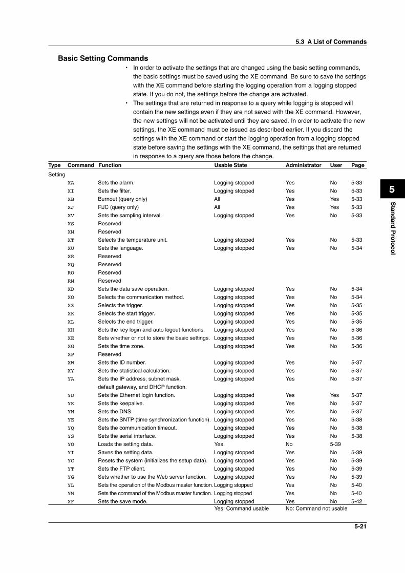
5-21
1
2
3
4
5
6
7
App
Index
Standard Protocol
Basic Setting Commands• In order to activate the settings that are changed using the basic setting commands,
the basic settings must be saved using the XE command. Be sure to save the settings with the XE command before starting the logging operation from a logging stopped state. If you do not, the settings before the change are activated.
• The settings that are returned in response to a query while logging is stopped will contain the new settings even if they are not saved with the XE command. However, the new settings will not be activated until they are saved. In order to activate the new settings, the XE command must be issued as described earlier. If you discard the settings with the XE command or start the logging operation from a logging stopped state before saving the settings with the XE command, the settings that are returned in response to a query are those before the change.
Type Command Function Usable State Administrator User PageSetting XA Sets the alarm. Logging stopped Yes No 5-33 XI Sets the filter. Logging stopped Yes No 5-33 XB Burnout (query only) All Yes Yes 5-33 XJ RJC (query only) All Yes Yes 5-33 XV Sets the sampling interval. Logging stopped Yes No 5-33 XS Reserved XM Reserved XT Selects the temperature unit. Logging stopped Yes No 5-33 XU Sets the language. Logging stopped Yes No 5-34 XR Reserved XQ Reserved RO Reserved RM Reserved XD Sets the data save operation. Logging stopped Yes No 5-34 XO Selects the communication method. Logging stopped Yes No 5-34 XZ Selects the trigger. Logging stopped Yes No 5-35 XK Selects the start trigger. Logging stopped Yes No 5-35 XL Selects the end trigger. Logging stopped Yes No 5-35 XH Sets the key login and auto logout functions. Logging stopped Yes No 5-36 XE Sets whether or not to store the basic settings. Logging stopped Yes No 5-36 XG Sets the time zone. Logging stopped Yes No 5-36 XP Reserved XW Sets the ID number. Logging stopped Yes No 5-37 XY Sets the statistical calculation. Logging stopped Yes No 5-37 YA Sets the IP address, subnet mask, Logging stopped Yes No 5-37 default gateway, and DHCP function. YD Sets the Ethernet login function. Logging stopped Yes Yes 5-37 YK Sets the keepalive. Logging stopped Yes No 5-37 YN Sets the DNS. Logging stopped Yes No 5-37 YE Sets the SNTP (time synchronization function). Logging stopped Yes No 5-38 YQ Sets the communication timeout. Logging stopped Yes No 5-38 YS Sets the serial interface. Logging stopped Yes No 5-38 YO Loads the setting data. Yes No 5-39 YI Saves the setting data. Logging stopped Yes No 5-39 YC Resets the system (initializes the setup data). Logging stopped Yes No 5-39 YT Sets the FTP client. Logging stopped Yes No 5-39 YG Sets whether to use the Web server function. Logging stopped Yes No 5-39 YL Sets the operation of the Modbus master function. Logging stopped Yes No 5-40 YM Sets the command of the Modbus master function. Logging stopped Yes No 5-40 XF Sets the save mode. Logging stopped Yes No 5-42 Yes: Command usable No: Command not usable
5.3 A List of Commands
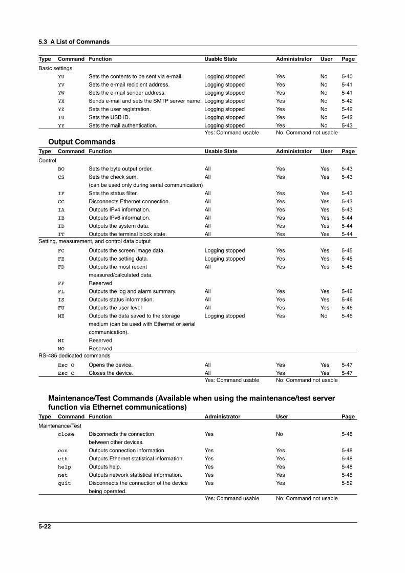
5-22
Type Command Function Usable State Administrator User PageBasic settings YU Sets the contents to be sent via e-mail. Logging stopped Yes No 5-40 YV Sets the e-mail recipient address. Logging stopped Yes No 5-41 YW Sets the e-mail sender address. Logging stopped Yes No 5-41 YX Sends e-mail and sets the SMTP server name. Logging stopped Yes No 5-42 YZ Sets the user registration. Logging stopped Yes No 5-42 IU Sets the USB ID. Logging stopped Yes No 5-42 YY Sets the mail authentication. Logging stopped Yes No 5-43 Yes: Command usable No: Command not usable
Output CommandsType Command Function Usable State Administrator User PageControl BO Sets the byte output order. All Yes Yes 5-43 CS Sets the check sum. All Yes Yes 5-43 (can be used only during serial communication) IF Sets the status filter. All Yes Yes 5-43 CC Disconnects Ethernet connection. All Yes Yes 5-43 IA Outputs IPv4 information. All Yes Yes 5-43 IB Outputs IPv6 information. All Yes Yes 5-44 ID Outputs the system data. All Yes Yes 5-44 IT Outputs the terminal block state. All Yes Yes 5-44Setting, measurement, and control data output FC Outputs the screen image data. Logging stopped Yes Yes 5-45 FE Outputs the setting data. Logging stopped Yes Yes 5-45 FD Outputs the most recent All Yes Yes 5-45 measured/calculated data. FF Reserved FL Outputs the log and alarm summary. All Yes Yes 5-46 IS Outputs status information. All Yes Yes 5-46 FU Outputs the user level All Yes Yes 5-46 ME Outputs the data saved to the storage Logging stopped Yes No 5-46 medium (can be used with Ethernet or serial communication). MI Reserved MO Reserved RS-485 dedicated commands Esc O Opens the device. All Yes Yes 5-47 Esc C Closes the device. All Yes Yes 5-47 Yes: Command usable No: Command not usable
Maintenance/Test Commands (Available when using the maintenance/test server function via Ethernet communications)
Type Command Function Administrator User PageMaintenance/Test close Disconnects the connection Yes No 5-48 between other devices. con Outputs connection information. Yes Yes 5-48 eth Outputs Ethernet statistical information. Yes Yes 5-48 help Outputs help. Yes Yes 5-48 net Outputs network statistical information. Yes Yes 5-48 quit Disconnects the connection of the device Yes Yes 5-52 being operated. Yes: Command usable No: Command not usable
5.3 A List of Commands
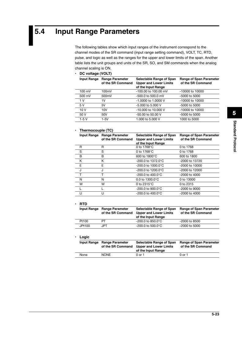
5-23
1
2
3
4
5
6
7
App
Index
Standard Protocol
5.4 Input Range Parameters
The following tables show which input ranges of the instrument correspond to the channel modes of the SR command (input range setting command), VOLT, TC, RTD, pulse, and logic as well as the ranges for the upper and lower limits of the span. Another table lists the unit groups and units of the SR, SO, and SM commands when the analog channel scaling is ON.• DC voltage (VOLT)
Input Range Range Parameter Selectable Range of Span Range of Span Parameter of the SR Command Upper and Lower Limits of the SR Command of the Input Range 100 mV 100mV -100.00 to 100.00 mV -10000 to 10000500 mV 500mV -500.0 to 500.0 mV -5000 to 50001 V 1V -1.0000 to 1.0000 V -10000 to 100005 V 5V -5.000 to 5.000 V -5000 to 500010 V 10V -10.000 to 10.000 V -10000 to 1000050 V 50V -50.00 to 50.00 V -5000 to 50001-5 V 1-5V 1.000 to 5.000 V 1000 to 5000
• Thermocouple (TC)Input Range Range Parameter Selectable Range of Span Range of Span Parameter of the SR Command Upper and Lower Limits of the SR Command of the Input Range R R 0 to 1768°C 0 to 1768S S 0 to 1768°C 0 to 1768B B 600 to 1800°C 600 to 1800K K -200.0 to 1372.0°C -2000 to 13720E E -200.0 to 1000.0°C -2000 to 10000J J -200.0 to 1200.0°C -2000 to 12000T T -200.0 to 400.0°C -2000 to 4000N N 0.0 to 1300.0°C 0 to 13000W W 0 to 2315°C 0 to 2315L L -200.0 to 900.0°C -2000 to 9000U U -200.0 to 400.0°C -2000 to 4000
• RTDInput Range Range Parameter Selectable Range of Span Range of Span Parameter of the SR Command Upper and Lower Limits of the SR Command of the Input Range Pt100 PT -200.0 to 850.0°C -2000 to 8500JPt100 JPT -200.0 to 500.0°C -2000 to 5000
• LogicInput Range Range Parameter Selectable Range of Span Range of Span Parameter of the SR Command Upper and Lower Limits of the SR Command of the Input Range None NONE 0 or 1 0 or 1
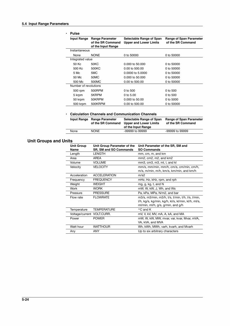
5-24
• PulseInput Range Range Parameter Selectable Range of Span Range of Span Parameter of the SR Command Upper and Lower Limits of the SR Command of the Input Range Instantaneous
None NONE 0 to 50000 0 to 50000Integrated value
50 Kc 50KC 0.000 to 50.000 0 to 50000 500 Kc 500KC 0.00 to 500.00 0 to 50000 5 Mc 5MC 0.0000 to 5.0000 0 to 50000 50 Mc 50MC 0.000 to 50.000 0 to 50000 500 Mc 500MC 0.00 to 500.00 0 to 50000Number of revolutions
500 rpm 500RPM 0 to 500 0 to 500 5 krpm 5KRPM 0 to 5.00 0 to 500 50 krpm 50KRPM 0.000 to 50.00 0 to 5000 500 krpm 500KRPM 0.00 to 500.00 0 to 50000
• Calculation Channels and Communication ChannelsInput Range Range Parameter Selectable Range of Span Range of Span Parameter of the SR Command Upper and Lower Limits of the SR Command of the Input Range None NONE -99999 to 99999 -99999 to 99999
Unit Groups and UnitsUnit Group Unit Group Parameter of the Unit Parameter of the SR, SM and Name SR, SM and SO Commands SO CommandsLength LENGTH mm, cm, m, and kmArea AREA mm2, cm2, m2, and km2Volume VOLUME mm3, cm3, m3, ml, l, and klVelocity VELOCITY mm/s, mm/min, mm/h, cm/s, cm/min, cm/h,
m/s, m/min, m/h, km/s, km/min, and km/hAcceleration ACCELERATION m/s2Frequency FREQUENCY mHz, Hz, kHz, rpm, and rphWeight WEIGHT mg, g, kg, t, and NWork WORK mW, W, kW, J, Wh, and WsPressure PRESSURE Pa, kPa, MPa, N/m2, and barFlow rate FLOWRATE m3/s, m3/min, m3/h, t/s, t/min, t/h, l/s, l/min,
l/h, kg/s, kg/min, kg/h, kl/s, kl/min, kl/h, ml/s, ml/min, ml/h, g/s, g/min, and g/h
Temperature TEMPERATURE ^C and KVoltage/current VOLT.CURR. mV, V, kV, MV, mA, A, kA, and MAPower POWER mW, W, kW, MW, mvar, var, kvar, Mvar, mVA,
VA, kVA, and MVAWatt hour WATTHOUR Wh, kWh, MWh, varh, kvarh, and MvarhAny ANY Up to six arbitrary characters
5.4 Input Range Parameters
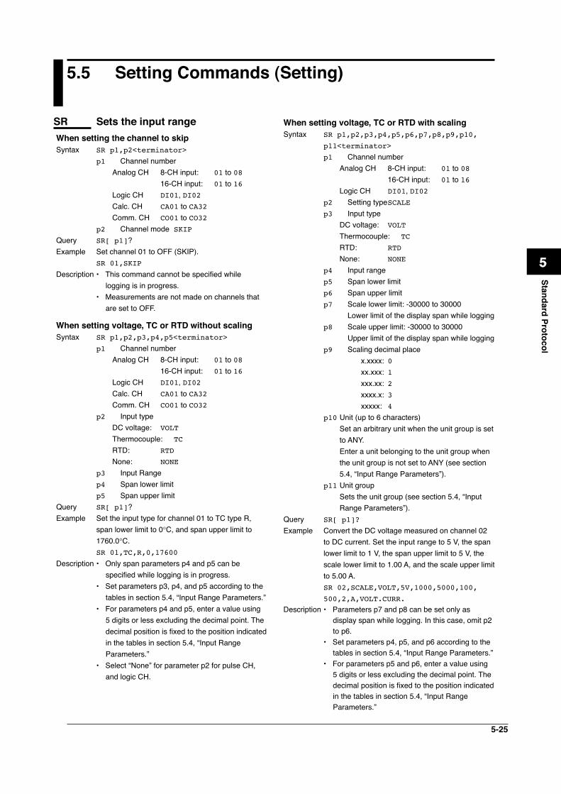
5-25
1
2
3
4
5
6
7
App
Index
Standard Protocol
5.5 Setting Commands (Setting)
SR Sets the input rangeWhen setting the channel to skipSyntax SR p1,p2<terminator>
p1 Channel number Analog CH 8-CH input: 01 to 08 16-CH input: 01 to 16 Logic CH DI01, DI02 Calc. CH CA01 to CA32 Comm. CH CO01 to CO32p2 Channel mode SKIP
Query SR[ p1]?Example Set channel 01 to OFF (SKIP).
SR 01,SKIP
Description • This command cannot be specified while logging is in progress.
• Measurements are not made on channels that are set to OFF.
When setting voltage, TC or RTD without scalingSyntax SR p1,p2,p3,p4,p5<terminator>
p1 Channel number Analog CH 8-CH input: 01 to 08 16-CH input: 01 to 16 Logic CH DI01, DI02 Calc. CH CA01 to CA32 Comm. CH CO01 to CO32p2 Input type DC voltage: VOLT
Thermocouple: TC
RTD: RTD
None: NONE
p3 Input Rangep4 Span lower limitp5 Span upper limit
Query SR[ p1]?Example Set the input type for channel 01 to TC type R,
span lower limit to 0°C, and span upper limit to 1760.0°C.SR 01,TC,R,0,17600
Description • Only span parameters p4 and p5 can be specified while logging is in progress.
• Set parameters p3, p4, and p5 according to the tables in section 5.4, “Input Range Parameters.”
• For parameters p4 and p5, enter a value using 5 digits or less excluding the decimal point. The decimal position is fixed to the position indicated in the tables in section 5.4, “Input Range Parameters.”
• Select “None” for parameter p2 for pulse CH, and logic CH.
When setting voltage, TC or RTD with scalingSyntax SR p1,p2,p3,p4,p5,p6,p7,p8,p9,p10,
p11<terminator>
p1 Channel number Analog CH 8-CH input: 01 to 08
16-CH input: 01 to 16 Logic CH DI01, DI02p2 Setting type SCALEp3 Input type DC voltage: VOLT
Thermocouple: TC
RTD: RTD
None: NONE
p4 Input rangep5 Span lower limitp6 Span upper limitp7 Scale lower limit: -30000 to 30000 Lower limit of the display span while loggingp8 Scale upper limit: -30000 to 30000 Upper limit of the display span while loggingp9 Scaling decimal place x.xxxx: 0 xx.xxx: 1 xxx.xx: 2 xxxx.x: 3 xxxxx: 4p10 Unit (up to 6 characters) Set an arbitrary unit when the unit group is set
to ANY. Enter a unit belonging to the unit group when
the unit group is not set to ANY (see section 5.4, “Input Range Parameters”).
p11 Unit group Sets the unit group (see section 5.4, “Input
Range Parameters”).Query SR[ p1]?
Example Convert the DC voltage measured on channel 02 to DC current. Set the input range to 5 V, the span lower limit to 1 V, the span upper limit to 5 V, the scale lower limit to 1.00 A, and the scale upper limit to 5.00 A.SR 02,SCALE,VOLT,5V,1000,5000,100,
500,2,A,VOLT.CURR.Description • Parameters p7 and p8 can be set only as
display span while logging. In this case, omit p2 to p6.
• Set parameters p4, p5, and p6 according to the tables in section 5.4, “Input Range Parameters.”
• For parameters p5 and p6, enter a value using 5 digits or less excluding the decimal point. The decimal position is fixed to the position indicated in the tables in section 5.4, “Input Range Parameters.”
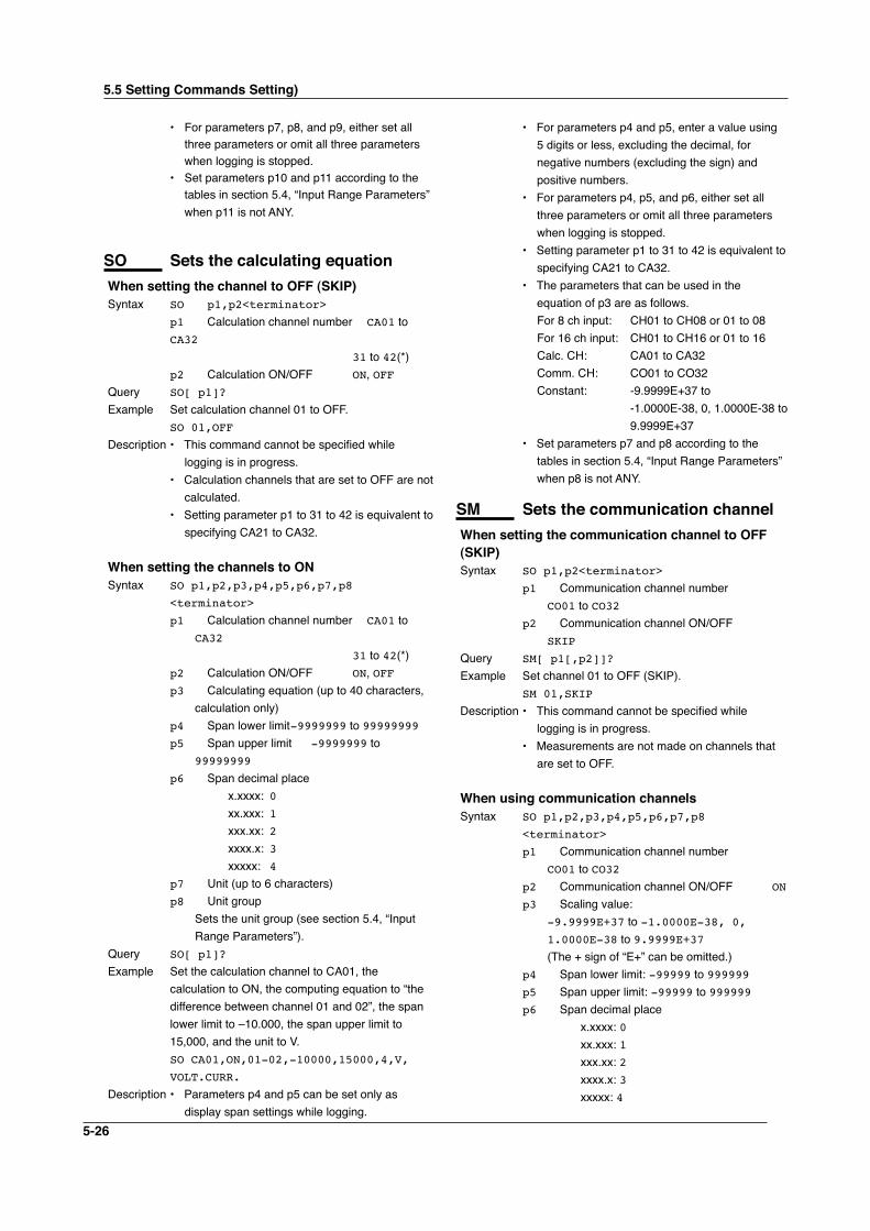
5-26
• For parameters p7, p8, and p9, either set all three parameters or omit all three parameters when logging is stopped.
• Set parameters p10 and p11 according to the tables in section 5.4, “Input Range Parameters” when p11 is not ANY.
SO Sets the calculating equationWhen setting the channel to OFF (SKIP)Syntax SO p1,p2<terminator>
p1 Calculation channel number CA01 to CA32 31 to 42(*)p2 Calculation ON/OFF ON, OFF
Query SO[ p1]?
Example Set calculation channel 01 to OFF. SO 01,OFF
Description • This command cannot be specified while logging is in progress.
• Calculation channels that are set to OFF are not calculated.
• Setting parameter p1 to 31 to 42 is equivalent to specifying CA21 to CA32.
When setting the channels to ONSyntax SO p1,p2,p3,p4,p5,p6,p7,p8
<terminator>
p1 Calculation channel number CA01 to CA32 31 to 42(*)
p2 Calculation ON/OFF ON, OFFp3 Calculating equation (up to 40 characters,
calculation only)p4 Span lower limit -9999999 to 99999999p5 Span upper limit -9999999 to
99999999
p6 Span decimal place x.xxxx: 0 xx.xxx: 1 xxx.xx: 2 xxxx.x: 3 xxxxx: 4p7 Unit (up to 6 characters)p8 Unit group Sets the unit group (see section 5.4, “Input
Range Parameters”).Query SO[ p1]?
Example Set the calculation channel to CA01, the calculation to ON, the computing equation to “the difference between channel 01 and 02”, the span lower limit to –10.000, the span upper limit to 15,000, and the unit to V.SO CA01,ON,01-02,-10000,15000,4,V,
VOLT.CURR.
Description • Parameters p4 and p5 can be set only as display span settings while logging.
• For parameters p4 and p5, enter a value using 5 digits or less, excluding the decimal, for negative numbers (excluding the sign) and positive numbers.
• For parameters p4, p5, and p6, either set all three parameters or omit all three parameters when logging is stopped.
• Setting parameter p1 to 31 to 42 is equivalent to specifying CA21 to CA32.
• The parameters that can be used in the equation of p3 are as follows.
For 8 ch input: CH01 to CH08 or 01 to 08 For 16 ch input: CH01 to CH16 or 01 to 16 Calc. CH: CA01 to CA32 Comm. CH: CO01 to CO32 Constant: -9.9999E+37 to
-1.0000E-38, 0, 1.0000E-38 to 9.9999E+37
• Set parameters p7 and p8 according to the tables in section 5.4, “Input Range Parameters” when p8 is not ANY.
SM Sets the communication channelWhen setting the communication channel to OFF (SKIP)Syntax SO p1,p2<terminator>
p1 Communication channel number CO01 to CO32
p2 Communication channel ON/OFF SKIP
Query SM[ p1[,p2]]?
Example Set channel 01 to OFF (SKIP). SM 01,SKIP
Description • This command cannot be specified while logging is in progress.
• Measurements are not made on channels that are set to OFF.
When using communication channelsSyntax SO p1,p2,p3,p4,p5,p6,p7,p8
<terminator>
p1 Communication channel number CO01 to CO32
p2 Communication channel ON/OFF ON
p3 Scaling value: -9.9999E+37 to -1.0000E-38, 0, 1.0000E-38 to 9.9999E+37 (The + sign of “E+” can be omitted.)p4 Span lower limit: -99999 to 999999p5 Span upper limit: -99999 to 999999p6 Span decimal place x.xxxx: 0 xx.xxx: 1 xxx.xx: 2 xxxx.x: 3 xxxxx: 4
5.5 Setting Commands Setting)
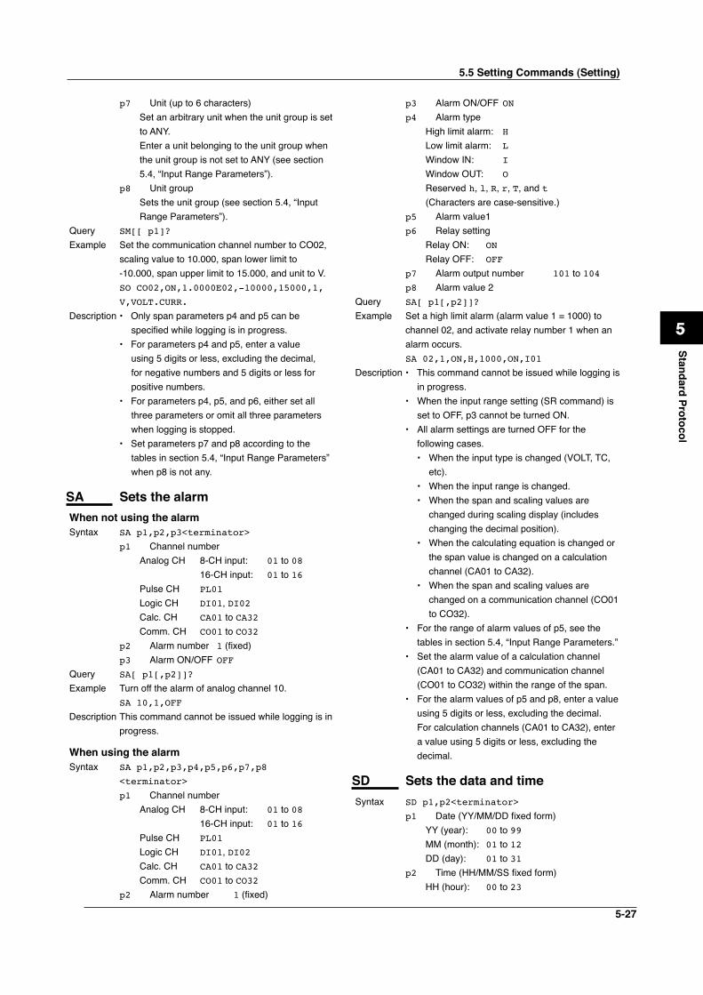
5-27
1
2
3
4
5
6
7
App
Index
Standard Protocol
p7 Unit (up to 6 characters) Set an arbitrary unit when the unit group is set
to ANY. Enter a unit belonging to the unit group when
the unit group is not set to ANY (see section 5.4, “Input Range Parameters”).
p8 Unit group Sets the unit group (see section 5.4, “Input
Range Parameters”).Query SM[[ p1]?
Example Set the communication channel number to CO02, scaling value to 10.000, span lower limit to -10.000, span upper limit to 15.000, and unit to V.SO CO02,ON,1.0000E02,-10000,15000,1,
V,VOLT.CURR.
Description • Only span parameters p4 and p5 can be specified while logging is in progress.
• For parameters p4 and p5, enter a value using 5 digits or less, excluding the decimal, for negative numbers and 5 digits or less for positive numbers.
• For parameters p4, p5, and p6, either set all three parameters or omit all three parameters when logging is stopped.
• Set parameters p7 and p8 according to the tables in section 5.4, “Input Range Parameters” when p8 is not any.
SA Sets the alarmWhen not using the alarmSyntax SA p1,p2,p3<terminator>
p1 Channel number Analog CH 8-CH input: 01 to 08
16-CH input: 01 to 16 Pulse CH PL01
Logic CH DI01, DI02 Calc. CH CA01 to CA32 Comm. CH CO01 to CO32p2 Alarm number 1 (fixed)p3 Alarm ON/OFF OFF
Query SA[ p1[,p2]]?
Example Turn off the alarm of analog channel 10. SA 10,1,OFF
Description This command cannot be issued while logging is in progress.
When using the alarmSyntax SA p1,p2,p3,p4,p5,p6,p7,p8
<terminator>
p1 Channel number Analog CH 8-CH input: 01 to 08
16-CH input: 01 to 16 Pulse CH PL01
Logic CH DI01, DI02 Calc. CH CA01 to CA32 Comm. CH CO01 to CO32p2 Alarm number 1 (fixed)
p3 Alarm ON/OFF ONp4 Alarm type High limit alarm: H Low limit alarm: L Window IN: I Window OUT: O Reserved h, l, R, r, T, and t (Characters are case-sensitive.)p5 Alarm value1p6 Relay setting Relay ON: ON Relay OFF: OFF
p7 Alarm output number 101 to 104p8 Alarm value 2
Query SA[ p1[,p2]]?
Example Set a high limit alarm (alarm value 1 = 1000) to channel 02, and activate relay number 1 when an alarm occurs.SA 02,1,ON,H,1000,ON,I01
Description • This command cannot be issued while logging is in progress.
• When the input range setting (SR command) is set to OFF, p3 cannot be turned ON.
• All alarm settings are turned OFF for the following cases.• When the input type is changed (VOLT, TC,
etc).• When the input range is changed.• When the span and scaling values are
changed during scaling display (includes changing the decimal position).
• When the calculating equation is changed or the span value is changed on a calculation channel (CA01 to CA32).
• When the span and scaling values are changed on a communication channel (CO01 to CO32).
• For the range of alarm values of p5, see the tables in section 5.4, “Input Range Parameters.”
• Set the alarm value of a calculation channel (CA01 to CA32) and communication channel (CO01 to CO32) within the range of the span.
• For the alarm values of p5 and p8, enter a value using 5 digits or less, excluding the decimal. For calculation channels (CA01 to CA32), enter a value using 5 digits or less, excluding the decimal.
SD Sets the data and timeSyntax SD p1,p2<terminator>
p1 Date (YY/MM/DD fixed form) YY (year): 00 to 99 MM (month): 01 to 12 DD (day): 01 to 31p2 Time (HH/MM/SS fixed form) HH (hour): 00 to 23
5.5 Setting Commands (Setting)
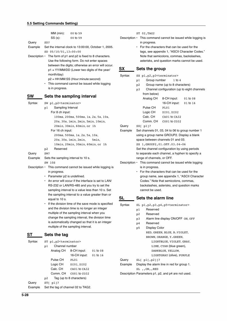
5-28
MM (min): 00 to 59 SS (s): 00 to 59
Query SD?
Example Set the internal clock to 13:00:00, October 1, 2005.SD 05/10/01,13:00:00
Description • The form of p1 and p2 is fixed to 8 characters. Use the following form. Do not enter spaces between the digits; otherwise an error will occur.
p1 = YY/MM/DD (Lower two digits of the year/month/day)
p2 = HH:MM:SS (Hour:minute:second)• This command cannot be issued while logging
is in progress.
SW Sets the sampling intervalSyntax SW p1,p2<terminator>
p1 Sampling Interval For 8 ch input: 100ms, 200ms, 500ms, 1s, 2s, 5s, 10s,
20s, 30s, 1min, 2min, 5min, 10min, 20min, 30min, 60min, or 1h
For 16 ch input: 200ms, 500ms, 1s, 2s, 5s, 10s,
20s, 30s, 1min, 2min, 5min,
10min, 20min, 30min, 60min, or 1hp2 Reserved
Query SW?
Example Sets the sampling interval to 10 s.SW 10S
Description • This command cannot be issued while logging is in progress.
• Parameter p2 is undefined.• An error wlll occur if the interface is set to LAN/
RS-232 or LAN/RS-485 and you try to set the sampling interval to a value less than 10 s. Set the sampling interval to a value greater than or equal to 10 s.
• If the division time of the save mode is specified and the division time is no longer an integer multiple of the sampling interval when you change the sampling interval, the division time is automatically changed so that it is an integer multiple of the sampling interval.
ST Sets the tagSyntax ST p1,p2<terminator>
p1 Channel number Analog CH 8-CH input: 01 to 08
16-CH input: 01 to 16 Pulse CH PL01
Logic CH DI01, DI02 Calc. CH CA01 to CA32 Comm. CH CO01 to CO32p2 Tag (up to 8 characters)
Query ST[ p1]?
Example Set the tag of channel 02 to TAG2.
ST 02,TAG2
Description • This command cannot be issued while logging is in progress.
• For the characters that can be used for the tags, see appendix 1, “ASCII Character Codes.” Note that semicolons, commas, backslashes, asterisks, and question marks cannot be used.
SX Sets the groupSyntax SX p1,p2,p3<terminator>
p1 Group number 1 to 4p2 Group name (up to 8 characters)p3 Channel configuration (up to eight channels
from below) Analog CH 8-CH input: 01 to 08
16-CH input: 01 to 16 Pulse CH PL01
Logic CH DI01, DI02 Calc. CH CA01 to CA32 Comm. CH CO01 to CO32
Query SX[ p1]?
Example Set channels 01, 03, 04 to 06 to group number 1 using a group name GROUP2. Display a blank space between channels 01 and 03.SX 1,GROUP2,01.OFF.03.04-06
Set the channel configuration by using periods to separate each channel, a hyphen to specify a range of channels, or OFF.
Description • This command cannot be issued while logging is in progress.
• For the characters that can be used for the group name, see appendix 1, “ASCII Character Codes.” Note that semicolons, commas, backslashes, asterisks, and question marks cannot be used.
SL Sets the alarm lineSyntax SL p1,p2,p3,p4,p5<terminator>
p1 Reservedp2 Reservedp3 Alarm line display ON/OFF ON, OFFp4 Reservedp5 Display Color RED, GREEN, BLUE, B.VIOLET,
BROWN, ORANGE, Y.GREEN,
LIGHTBLUE, VIOLET, GRAY, LIME, CYAN (blue green),
DARKBLUE, YELLOW,
LIGHTGRAY (olive), PURPLEQuery SL[ p1[,p2]]?
Example Display the alarm line in red for group 1.SL ,,ON,,RED
Description Parameters p1, p2, and p4 are not used.
5.5 Setting Commands Setting)
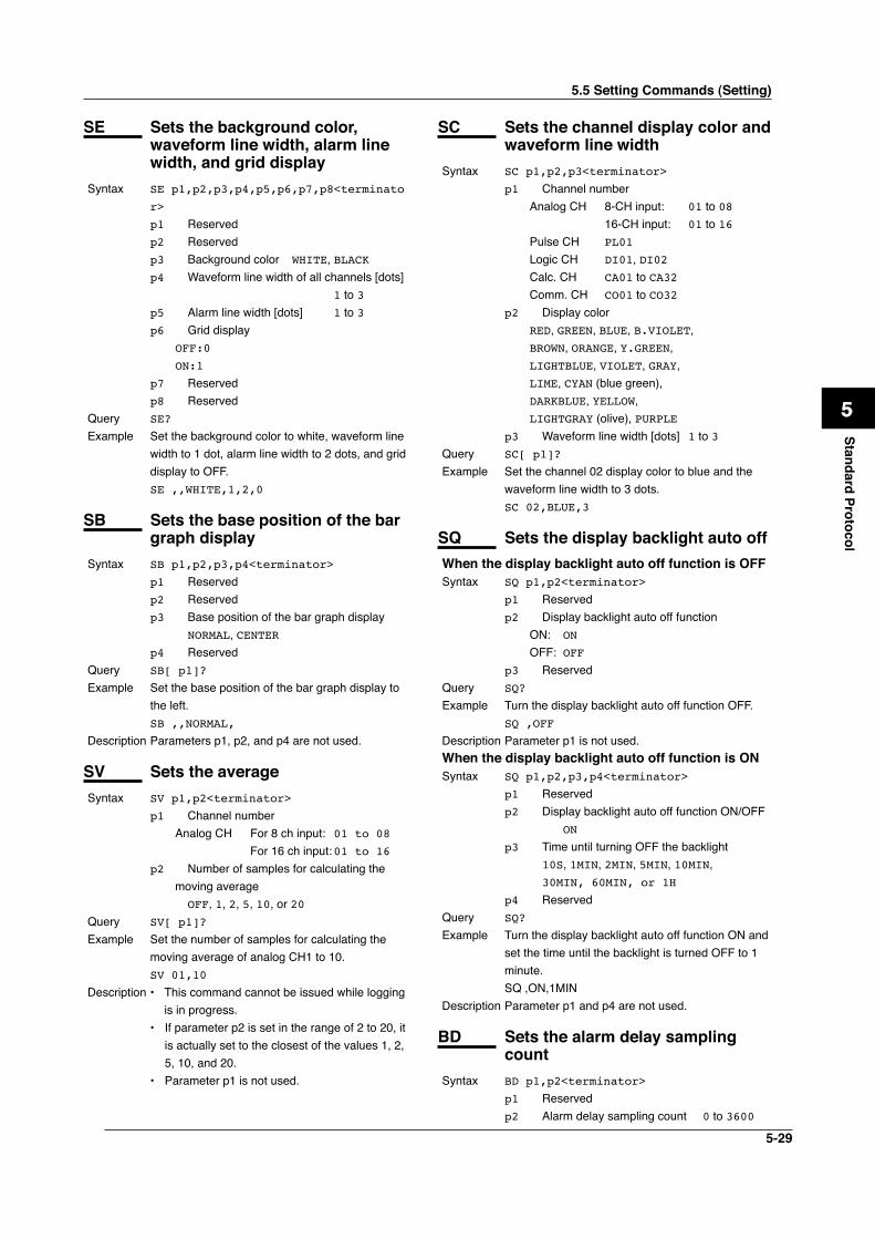
5-29
1
2
3
4
5
6
7
App
Index
Standard Protocol
SE Sets the background color, waveform line width, alarm line width, and grid display
Syntax SE p1,p2,p3,p4,p5,p6,p7,p8<terminato
r>
p1 Reservedp2 Reservedp3 Background color WHITE, BLACKp4 Waveform line width of all channels [dots]
1 to 3p5 Alarm line width [dots] 1 to 3p6 Grid display OFF:0
ON:1
p7 Reservedp8 Reserved
Query SE?
Example Set the background color to white, waveform line width to 1 dot, alarm line width to 2 dots, and grid display to OFF.SE ,,WHITE,1,2,0
SB Sets the base position of the bar graph display
Syntax SB p1,p2,p3,p4<terminator>
p1 Reservedp2 Reservedp3 Base position of the bar graph display NORMAL, CENTERp4 Reserved
Query SB[ p1]?
Example Set the base position of the bar graph display to the left.SB ,,NORMAL,
Description Parameters p1, p2, and p4 are not used.
SV Sets the averageSyntax SV p1,p2<terminator>
p1 Channel number Analog CH For 8 ch input: 01 to 08 For 16 ch input: 01 to 16p2 Number of samples for calculating the moving average OFF, 1, 2, 5, 10, or 20
Query SV[ p1]?
Example Set the number of samples for calculating the moving average of analog CH1 to 10.SV 01,10
Description • This command cannot be issued while logging is in progress.• If parameter p2 is set in the range of 2 to 20, it
is actually set to the closest of the values 1, 2, 5, 10, and 20.
• Parameter p1 is not used.
SC Sets the channel display color and waveform line width
Syntax SC p1,p2,p3<terminator>
p1 Channel number Analog CH 8-CH input: 01 to 08
16-CH input: 01 to 16 Pulse CH PL01
Logic CH DI01, DI02 Calc. CH CA01 to CA32 Comm. CH CO01 to CO32p2 Display color RED, GREEN, BLUE, B.VIOLET,
BROWN, ORANGE, Y.GREEN,
LIGHTBLUE, VIOLET, GRAY,
LIME, CYAN (blue green),
DARKBLUE, YELLOW,
LIGHTGRAY (olive), PURPLE p3 Waveform line width [dots] 1 to 3Query SC[ p1]?
Example Set the channel 02 display color to blue and the waveform line width to 3 dots.SC 02,BLUE,3
SQ Sets the display backlight auto offWhen the display backlight auto off function is OFFSyntax SQ p1,p2<terminator>
p1 Reserved p2 Display backlight auto off function ON: ON
OFF: OFFp3 Reserved
Query SQ?
Example Turn the display backlight auto off function OFF.SQ ,OFF
Description Parameter p1 is not used.When the display backlight auto off function is ONSyntax SQ p1,p2,p3,p4<terminator>
p1 Reserved p2 Display backlight auto off function ON/OFF ON
p3 Time until turning OFF the backlight 10S, 1MIN, 2MIN, 5MIN, 10MIN, 30MIN, 60MIN, or 1H
p4 ReservedQuery SQ?
Example Turn the display backlight auto off function ON and set the time until the backlight is turned OFF to 1 minute.SQ ,ON,1MIN
Description Parameter p1 and p4 are not used.
BD Sets the alarm delay sampling count
Syntax BD p1,p2<terminator>
p1 Reservedp2 Alarm delay sampling count 0 to 3600
5.5 Setting Commands (Setting)
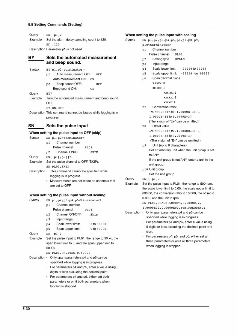
5-30
Query BD[ p1]?
Example Set the alarm delay sampling count to 120.BD ,120
Description Parameter p1 is not used.
BY Sets the automated measurement and beep sound.
Syntax BY p1,p2<terminator>
p1 Auto measurement OFF: OFF
Auto measurement ON: ON
p2 Beep sound OFF: OFF
Beep sound ON: ON
Query BY?
Example Turn the automated measurement and beep sound OFF.BY ON,OFF
Description This command cannot be issued while logging is in progress.
SN Sets the pulse inputWhen setting the pulse input to OFF (skip)Syntax SN p1,p2<terminator>
p1 Channel number Pulse channel PL01
p2 Channel ON/OF SKIP
Query SN[ p1[,p2]]?
Example Set the pulse channel to OFF (SKIP).SN PL01,SKIP
Description • This command cannot be specified while logging is in progress.
• Measurements are not made on channels that are set to OFF.
When setting the pulse input without scalingSyntax SN p1,p2,p3,p4,p5<terminator>
p1 Channel number Pulse channel PL01
p2 Channel ON/OFF Skip
p3 Input rangep4 Span lower limit: 0 to 50000p5 Span upper limit: 0 to 50000
Query SN[ p1]?
Example Set the pulse input to PL01, the range to 50 kc, the span lower limit to 0, and the span upper limit to 50000.SN PL01,ON,50KC,0,50000
Description • Only span parameters p4 and p5 can be specified while logging is in progress.
• For parameters p4 and p5, enter a value using 5 digits or less excluding the decimal point.
• For parameters p4 and p5, either set both parameters or omit both parameters when logging is stopped.
When setting the pulse input with scalingSyntax SN p1,p2,p3,p4,p5,p6,p7,p8,p9,
p10<terminator>
p1 Channel number Pulse channel PL01
p2 Setting type SCALE
p3 Input rangep4 Scale lower limit: -99999 to 99999p5 Scale upper limit: -99999 to 99999
p6 Span decimal place x.xxxx: 0 xx.xxx: 1 xxx.xx: 2 xxxx.x: 3 xxxxx: 4P7 Conversion ratio: -9.9999E+37 to -1.0000E-38, 0,
1.0000E-38 to 9.9999E+37 (The + sign of “E+” can be omitted.)P8 Offset value: -9.9999E+37 to -1.0000E-38, 0,
1.0000E-38 to 9.9999E+37 (The + sign of “E+” can be omitted.)p9 Unit (up to 6 characters) Set an arbitrary unit when the unit group is set
to ANY. If the unit group is not ANY, enter a unit in the
unit group.p10 Unit group Set the unit group.
Query SN[[ p1]?
Example Set the pulse input to PL01, the range to 500 rpm, the scale lower limit to 0.00, the scale upper limit to 600.00, the conversion ratio to 10.000, the offset to 0.000, and the unit to rpm.SN PL01,SCALE,500RPM,0,60000,2,
1.0000E02,0.0000E00,rpm,FREQUENCY
Description • Only span parameters p4 and p5 can be specified while logging is in progress.
• For parameters p4 and p5, enter a value using 5 digits or less excluding the decimal point and sign.
• For parameters p4, p5, and p6, either set all three parameters or omit all three parameters when logging is stopped.
5.5 Setting Commands (Setting)
5-31
1
2
3
4
5
6
7
App
Index
Standard Protocol
5.6 Setting Commands (Control)
EV Saves the manual sampled data or screen image data to the storage medium
Syntax EV p1<terminator>
p1 Operation typeSaves manual sampled data to the storage medium: 0
Saves screen image data to the storage medium: 2
Reserved: 1, 3, 4Example Saves manual sampled data to the storage
medium.EV 1
Description • Data cannot be saved while logging.• Parameter p1 cannot be set to 0 while the
storage medium is being formatted or while data is being saved to the storage medium.
LO Loads the setup dataSyntax LO p1 <terminator>
p1 Path name (up to 150 characters) Setting memory: /SETMEMORY/file name
(excluding the extension) Internal memory: /INTERNALMEMORY/file
name (excluding the extension) CF memory card: /CFCARD/file name
(excluding the extension) SD memory card: /SDCARD/file name
(excluding the extension)Example Load the setting data of setup file SETFILE1 (.SET
extension) from the setting memory.LO /SETMEMORY/SETFILE1
Description • This command is the same as the YO command. To apply the functions of the basic setting commands, the settings must be saved using the XE command.
• This command can be issued only when the path is specified and the corresponding storage medium is inserted.
LI Saves the setting dataSyntax LI p1 <terminator>
p1 Path name (up to 150 characters) Setting memory: /SETMEMORY/file name
(excluding the extension) Internal memory: /INTERNALMEMORY/file
name (excluding the extension) CF memory card: /CFCARD/file name
(excluding the extension) SD memory card: /SDCARD/file name
(excluding the extension)
UD Switches the displayWhen switching the display back to the display that existed before settings were changed using communication commandsSyntax UD p1<terminator>
p1 Display switching 0Example Switch the display back to the display that
existed before settings were changed using communication commands.UD 0
When switching the display using communication commandsSyntax UD p1,p2,p3<terminator>
p1 Display switching 1
p2 Display item Waveform & digital display: TREND
Digital display: DIGITAL Bar graph display: BAR
Alarm summary display: ALARM
Review display: REVIEW
Reserved: OVERVIEW p3 Group number 1 to 4
Example Set the display to waveform & digital, and set the number of the group to be displayed to 4.UD 1,TREND,4
Description • This command is valid only when the current display is one of the displays of p2.
• If p2 is set to alarm summary display, p3 is discarded.
PS Starts/Stops loggingSyntax PS p1<terminator>
p1 Logging start/stop Start: 0 Stop: 1
Example Start logging.PS 0
Description If the logging start trigger is set to manual and logging does not start immediately, the GS610 enters logging standby until the trigger condition is met.
AK Acknowledges the alarm status (alarm acknowledge)
Syntax AK p1<terminator>
p1 Execute alarm acknowledge 0
Example Confirm the current hold condition of the alarm (execute alarm acknowledge).AK 0
5-32
Example Save the setting data to a file named SETFILE2 on the CF memory card.LI /CFCARD/SETFILE2
Description • A “.SET” extension is attached to the saved file. This command is equivalent to the YI command.
• The settings are not saved with this command if an external storage media error occurs such as the external storage medium not inserted at the save destination.
CM Sets the communication input data
Syntax CM p1,p2<terminator>
p1 Communication input data number C01 to C32 (same as CO01 to CO32) CO01 to CO32p2 Communication input data Selectable range: -9.9999E+29 to -
1.0000E- 30, 0,
1.0000E-30 to -9.9999E+29
(The + sign of “E+” can be omitted.)
Query CM1?
Example Set 1.0000E-10 to communication input data number CO01.CM CO01,1.0000E-10
EM Starts/stops the e-mail transmission function
Syntax M p1<terminator>
p1 Operation type Start: 0 Stop: 1
Example Start the e-mail transmission function.EM 0
Description To use the e-mail transmission function, you must set the Ethernet interface, e-mail address, and contents to be transmitted. For the procedure to set each item, see section 2.11 “Setting the E-mail Transmission function”.
KE Key operation commandSyntax KE p1<terminator>
p1 Key type ESC key: ESC HOME key: HOME REVIEW key: REVIEW
FILE key: FILE SETTING key: SETTING HOLD key (hold down): LONGHOLD TIME/DIV left key: TIMEDIVSHORT TIME/DIV right key: TIMEDIVLONG
RANGE key: RANGE SAVE key: SAVE
DISPLAY key: DISP GROUP key: GROUP MARK key: MARK MARK left key: MARKLEFT MARK right key: MARKRIGHT
SET key: SET
START/STOP key: STARTSTOP Up arrow key: UP
Down arrow key: DOWN
Right arrow key: RIGHT
Left arrow key: LEFT SELECT key: SELECT
Example Press the DISPLAY key.KE DISP
Description Operates in the same fashion as the key operation on the XL100. For consecutive key operations, transmit the commands in the same order as the key operation on the XL100.
BZ Sets the activation of the setting commands.
Syntax BZ p1<terminator>
p1 Activation method of setting commands Activate after the setting command is
executed (default): 1 Activate when the settings are saved using
the XE command after executing the setting command: 0
Query BZ?
Example Activate the setting commands when the settings are saved using the XE command as with basic setting commands.BZ 0
Description • The default setting (the response to BZ? is BZ 1) is always in effect at power-on.
• This command is activated immediately.
5.6 Setting Commands (Control)
5-33
1
2
3
4
5
6
7
App
Index
Standard Protocol
5.7 Basic Setting Commands
None: OFF
50 Hz: 50Hz
60 Hz: 60Hz
Query XI?
Example Set the filter to 60 Hz.XI 60HZ
Description In order to activate the settings that are changed using the basic setting commands, the settings must be saved using the XE command. If you do not, the settings before the change are activated if logging is started.
XB Burnout setting (query only)Syntax XB p1,p2<terminator>
p1 Channel number For 8 ch input: 01 to 08 For 16 ch input: 01 to 16p2 Burnout procedure UP(fixed)
Query XB[ p1]? Description Only a query is available for this command.
XJ RJC setting (query only)Syntax XJ p1,p2<terminator>
p1 Channel number For 8 ch input: 01 to 08 For 16 ch input: 01 to 16p2 Reference junction compensation selection
INTERNAL
Query XJ[ p1]? Example Only a query is available for this command.
XV Sets the sampling intervalSyntax XV p1<terminator>
p1 Sampling Interval For 8 ch input: 100MS, 200MS, 500MS, 1S, 2S, 5S,
10S, 20S, 30S, 1MIN, 2MIN, 5MIN,
10MIN, 20MIN, 30MIN, 60MIN, 1H
For 16 ch input: 200MS, 500MS, 1S, 2S, 5S, 10S,
20S, 30S, 1MIN, 2MIN, 5MIN,
10MIN, 20MIN, 30MIN, 60MIN, 1H
Query XV?
Example Set the sampling interval to 1 s.XV 1S
Description • This command is the same as the SW setting command.
• An error will occur if the interface is set to LAN/RS-232 or LAN/RS-485 and you try to set the sampling interval to a value less than 10 s.
Set the sampling interval to a value greater than or equal to 10 s.
• In order to activate the settings that are changed using the basic setting commands, the settings must be saved using the XE command.
The settings that are returned in response to a query after issuing a basic setting command are the new settings even if the settings have not been saved with the XE command. However, the new settings only take effect after saving the settings using the XE command.
If you discard the settings with the XE command or start the logging operation before saving the settings with the XE command, the settings that are returned in response to a query are reset to those before the change.
• Basic setting commands cannot be used to change settings while logging is in progress.
XA Sets the alarmSyntax XA p1,p2,p3,p4,p5,p6,p7,p8,p9<termina
tor>
p1 Reservedp2 Output number to be set to AND For all ORs: NONE
Independent setting: I01, I02, I03, or I04
Range setting: I0x-I0y
(I0x,I0y:I01toI04)
Multiple settings (delimit using a period): I0w.I0y.I0z
(I0w,I0y,I0z:I01 to
I04)
p3 Reservedp4 Output hold/non-hold Hold: HOLD
Non-hold: NONHOLD
p5 Hold/Not hold the alarm status display Hold: HOLD
Non-hold: NONHOLD
p6 Reservedp7 Reservedp8 Alarm hysteresis ON/OFF: ON or OFFp9 Alarm buzzer ON/OFF: ON, OFF
Query XA? Example Set output numbers I01 to I04 to AND, hold the
output, hold the alarm status display, turn the alarm hysteresis ON, and turn the alarm buzzer ON.XA ,I01-I12,HOLD,HOLD,,,ON,ON
Description Parameters p1, p3, p6, and p7 are not used.
XI Sets the filter.Syntax XI p1<terminator>
p1 Filter setting
5-34
• If the division time of the save mode is specified and the division time is no longer an integer multiple of the sampling interval when you change the sampling interval, the division time is automatically changed so that it is an integer multiple of the sampling interval.
XU Sets the languageSyntax XU p1,p2,p3,p4,p5<terminator>
p1 Reservedp2 Reservedp3 English: ENGLISH
Japanese: JAPANESE
p4 Reservedp5 Reserved
Query XU?
Example Set the language to Japanese.XU ,,JAPANESE
Description Parameters p1, p2, p4, and p5 are undefined.
XD Sets the data save operationSyntax XD p1,p2,p3,p4 <terminator>
p1 Data save medium Internal memory: 0 CF card: 1
SD card: 2
p2 Data type Binary format: BINARY
ASCII format: ASCII
p3 File name Between 1 and 12 characters: Saves the data to a specified file name When omitted:
The file name is automatically assigned by the XL100.
p4 Printer output ON: ON
OFF: OFF
Query XD?
Example Set the data save destination to the CF card, the save format to binary, the file name to abcdef, and the printer output to OFF.XD 1,BINARY,abcdef,OFF
Description • If the file name of parameter p3 is omitted, the XL100 is set in a mode in which the file name is automatically assigned while logging. For details, see the XL100 User’s Manual.
• In order to activate the settings that are changed using the basic setting commands, the settings must be saved using the XE command. If you do not, the settings before the change are activated if logging is started.
• If the memory full operation of the save mode is set to REPEAT or DELETE and the data type
is set to ASCII, the operation is automatically changed to STOP.
XO Selects the communication method
When switching to Ethernet communicationsSyntax XO p1,p2<terminator>
p1 Ethernet communication ETHERNET
p2 Interface used simultaneously Ethernet interface only: OFF
RS-232: RS-232
RS-485: RS-485
Query XO?
Example Set the communication method to simultaneous use of the Ethernet and RS-485.XO ETHERNET,RS-485
Description If the communication method is set to Ethernet and RS-232 or Ethernet and RS-485, the sampling interval is automatically changed to 10 s if it is less than 10 s and the Modbus master read cycle is automatically changed to 5 s, if it is less than 5 s.
When switching to serial communications (RS-232, RS-485, or USB)Syntax XO p1,p2<terminator>
p1 Serial communications SERIALp2 Serial communication type RS232, RS485, or USB
Query XO?
Example Set the communication method to RS-232.XO SERIAL,RS232
When switching to serial communication printer connection (RS-232PRINTER communication)Syntax XO p1,p2,p3 <terminator>
p1 Serial communication SERIAL p2 Serial communication type
RS232PRINTER
p3 Manual printout OFF: 0
Measured data: 1
Screen data: 2
Measured/Screen data: 3
Query XO?
Example Set the XL100 to print only the measured data during the manual printout.XO SERIAL,RS232PRINTER,1
XZ Selects the triggerSyntax XZ p1,p2<terminator>
p1 Trigger mode Single: 0
Continuous: 1
p2 Pre-trigger and delay trigger setting Pre-trigger: 1
Delay trigger: 2p3 Pre-trigger or delay trigger count
0 to 600
5.7 Basic Setting Commands
5-35
1
2
3
4
5
6
7
App
Index
Standard Protocol
Query XZ?
Example Set the trigger to single and the pre-trigger count to 10.XZ 0,1,10
Description If the start trigger and end trigger are set to Time and the trigger mode is set to Continuous, the start trigger and end trigger are automatically set to None.
XK Selects the start triggerWhen setting the start trigger to noneSyntax XK p1 <terminator>
p1 Start trigger type None: 0
Query XK?
Example Set the start trigger to none.XK 0
When setting the start trigger to external inputSyntax XK p1<terminator>
p1 Start trigger type External input: 1
Query XK?
Example Set the start trigger to external input.XK 1
When setting the start trigger to the input levelSyntax XK p1,p2,p3,p4,p5 <terminator>
p1 Start trigger type Analog input level: 2p2 Channel to be used as the start trigger For 8 ch input: 01 to 08 For 16 ch input: 01 to 16 Pulse CH: PL01
Calculation CH: CA01 to CA32
Communication CH: CO01 to CO32
p3 Start trigger level type High limit trigger: H Low limit trigger: L Window IN: I
Window OUT: O
p4 High limit value -99999 to 99999
p5 Low limit value -99999 to 99999
Query XK?
Example Set the start trigger to Window IN of analog input CH3, and set the high and low limits to 2000 and 1000, respectively.XK 2,03,I,2000,1000
Description Set the high and low limits using a five-digit integer without a decimal point. The decimal place is the same as the span and scale settings of the analog input channel.
Be sure to set the high limit greater than the low limit.
When setting the start trigger to an alarmSyntax XK p1,p2<terminator>
p1 Start trigger type
Alarm: 3
p2 Alarm output number to be used as the start trigger
1 to 4Query XK?
Example Set the start trigger to alarm output number 4.XK 3,4
When setting the start trigger to a specific timeSyntax XK p1,p2,p3<terminator>
p1 Start trigger type Time: 4p2 Start date (YY/MM/DD fixed form) YY (year): 00 to 99 MM (month): 01 to 12 DD (day): 01 to 31p3 Start time (HH/MM/SS fixed form) HH (hour): 00 to 23 MM (min): 00 to 59 SS (s): 00 to 59
Query XK?
Example Set the start trigger to 3:45:6 on January 2, 2006.XK 4,06/01/02,03:45:06
Description If the trigger mode is set to repeat, the start trigger cannot be set to time.
XL Selects the end triggerWhen setting the end trigger to noneSyntax XL p1<terminator>
p1 End trigger type None: 0
Query XL?
Example Set the end trigger to none.XL 0
When setting the end trigger to external inputSyntax XL p1<terminator>
p1 End trigger type External input: 1
Query XL?
Example Set the end trigger to external input.XL 1
When setting the end trigger to input levelSyntax XL p1,p2,p3,p4,p5<terminator>
p1 End trigger type Input level: 2p2 Channel to be used as the end trigger Analog CH For 8 ch input: 01 to 08 For 16 ch input: 01 to 16 Pulse CH: PL01
Calculation CH: CA01 to CA32
Communication CH: CO01 to CO32
p3 End trigger level type High limit trigger: H Low limit trigger: L
Window IN: I
Window OUT :Op4 High limit value -99999 to 99999
5.7 Basic Setting Commands
5-36
p5 Low limit value -99999 to 99999Query XL?
Example Set the end trigger to low limit 500 of analog input CH3.XL 2,03,L,500
Description Set the high and low limits using a five-digit integer without a decimal point. The decimal place is the same as the span and scale settings of the analog input channel.
Be sure to set the high limit greater than the low limit.
When setting the end trigger to an alarmSyntax XL p1,p2<terminator>
p1 End trigger type Alarm: 3
p2 Alarm output number to be used as the end trigger
1 to 4Query XL?
Example Set the end trigger to alarm output number 1.XL 3,1
When setting the end trigger to a specific timeSyntax XL p1,p2,p3<terminator>
p1 End trigger type Time: 4p2 End date (YY/MM/DD fixed form) YY (year): 00 to 99 MM (month): 01 to 12 DD (day): 01 to 31p3 End time (HH/MM/SS fixed form) HH (hour): 00 to 23 MM (min): 00 to 59 SS (s): 00 to 59
Query XK?
Example Set the end trigger to 4:56:7 on February 3, 2030.XL 4,30/02/03,04:56:07
Description If the trigger mode is set to repeat, the end trigger cannot be set to time.
When setting the end trigger to a timerSyntax XL p1,p2<terminator>
p1 End trigger type Timer: 5
p2 End timer (s) 1 to 31536000
Query XL?
Example Set the end trigger to a 600-s timer.XL 5,600
XH Sets the key login and auto logout functions
Syntax XH p1,p2,p3<terminator>
p1 Key login function Enable: USE
Disable: NOT
p2 Timeout function
Enable: ON
Disable: OFF
p3 ReservedQuery XH?
Example Enable the key login and auto logout functions.XH USE,ON,
Description Parameter p3 is not used.
XE Sets whether to save or discard the settings specified by a basic setting command
Syntax XE p1<terminator>
p1 Save or discard settings Save: STORE
Discard: ABORT
Example Save the settings of the basic setting command.XE STORE
Description • In order to activate the settings that are changed using the basic setting commands, the settings must be saved using the XE command. If you do not, the settings before the change are activated if logging is started.
• If the setting command is set to activate when the settings are saved using the XE command (the condition which BZ 0 is specified), the items specified with the setting commands are activated when the settings are saved using the XE command.
XG Sets the time zoneSyntax XG p1,p2<terminator>
p1 Offset time from the Greenwich Mean Time -1200 to 1300
Upper two digits (hour): -12 to 13 Lower 2 digits (minute): 00 to 59
(See appendix 4, “Time Zones” and the XG command parameters.)
p2 Region number of the corresponding offset time zone 0 to 5
(See appendix 4, “Time Zones” and the XG command parameters.)
Example Set the time zone to “Osaka, Sapporo, Tokyo” (9 hour offset from Greenwich Mean Time and region number to 2).XG 0900,2
XW Sets the ID numberSyntax XW p1<terminator>
p1 ID number 1 to 99Query XW?
Example Set the ID number to 10.XW 10
Description • The ID number corresponds to the hardware ID number.
• In order to activate the settings that are changed using the basic setting commands, the settings must be saved using the XE command. If you
5.7 Basic Setting Commands
5-37
1
2
3
4
5
6
7
App
Index
Standard Protocol
do not, the settings before the change are activated if logging is started.
XY Sets the statistical calculationSyntax XY p1,p2,p3,p4,p5<terminator>
p1 Calculation of the maximum value Enable: ON
Disable: OFF
p2 Calculation of the minimum value Enable: ON
Disable: OFF
p3 Calculation of the average value Enable: ON
Disable: OFF
p4 Calculation of the peak (P-P) value Enable: ON
Disable: OFF
p5 Calculation of the rms value Enable: ON
Disable: OFF
Query XY?
YA Sets the IP address, subnet mask, default gateway, and DHCP function
Syntax YA p1,p2,p3,p4<terminator>
p1 IP address 0.0.0.0 to 255.255.255.255p2 Subnet mask 0.0.0.0 to 255.255.255.255p3 Default gateway 0.0.0.0 to 255.255.255.255p4 DHCP function enable/disable Disable
OFF
Query YA?
Example Set the IP address to 192.168.111.24, the subnet mask to 255.255.255.0, and the default gateway to 192.168.111.1 without using the DHCP function.YA 192.168.111.24,255.255.255.0,
192.168.111.1,OFF
Description The settings changed with this command are applied when they are saved using the XE command.
When using the DHCP (automatic IP address assignment) functionSyntax YA p1,p2,p3,p4<terminator>
p1 IP address 0.0.0.0 to 255.255.255.255p2 Subnet mask 0.0.0.0 to 255.255.255.255p3 Default gateway 0.0.0.0 to 255.255.255.255p4 DHCP function enable/disable Enable ON
Query YA?
Example Use the DHCP function.
YA ,,,ON
Description • If p4 is set to ON, p1, p2, and p3 are invalid. • The settings changed with this command are
applied when they are saved using the XE command.
YD Sets the Ethernet login function.Syntax YD p1<terminator>
p1 Ethernet login function setting ON: ON
OFF: OFF
Query YD?
Example Turns the Ethernet login function ON.YD ON
Description The setting changed with this command is applied when it is saved using the XE command.
YK Sets the keepaliveSyntax YK p1<terminator>
p1 Enable/Disable keepalive Enable: ON
Disable: OFF
Query YK?
Example Disable keepalive.YK OFF
Description The setting changed with this command is applied when it is saved using the XE command.
YN Sets the DNSWhen not using the DNSSyntax YN p1<terminator>
p1 Disable DNS OFF
Query YN?
Example Do not use the DNS.YN OFF
Description The setting changed with this command is applied when it is saved using the XE command.
When using the DNSSyntax YN p1,p2,p3,p4,p5,p6,p7<terminator>
p1 Enable DNS ON
p2 Address of the primary DNS server 0.0.0.0 to 255.255.255.255p3 Address of the secondary DNS server 0.0.0.0 to 255.255.255.255p4 Host name (up to 64 characters)p5 Domain name (up to 64 characters)p6 Domain suffix 1 (up to 64 characters)p7 Domain suffix 2 (up to 64 characters)
Query YN?
Example Use the DNS server at 192.168.0.1.YN ON,192.168.0.1
5.7 Basic Setting Commands
5-38
Description The settings changed with this command are applied when they are saved using the XE command.
YE Sets the SNTP (time synchronization function)
When not using the SNTPSyntax YE p1<terminator>
p1 Disable 0Query YE?
Example Disable SNTP.YE 0
When using the SNTPSyntax YE p1,p2,p3<terminator>
p1 Enable 1p2 Server name (up to 64 characters)p3 Confirmation time interval (hh) 1
to 24Query YE?
Example Use the SNTP server named MCC at six-hour intervals.YE 1,MCC,6
YQ Sets the Ethernet communication timeout
When not using the timeoutSyntax YQ p1<terminator>
p1 Enable/Disable communication timeout Enable: ON
Disable: OFF
Query YQ?
Example Disable timeout.YQ OFF
Description The setting changed with this command is applied when it is saved using the XE command.
When using the timeoutSyntax YQ p1,p2<terminator>
p1 Enable/Disable communication timeout Enable: ON
Disable: OFF
p2 Timeout value (min) 1 to 120Query YQ?
Example Enable the communication timeout and set the timeout period to 3 min.YQ ON,3
Description The settings changed with this command are applied when they are saved using the XE command.
YS Sets the serial interfaceSyntax YS p1,p2,p3,p4,p5,p6,p7<terminator>
p1 Baud rate [bps] When the interface is set to RS-232 or
RS-232 (printer): 2400, 4800, 9600, 19200, or 38400 When the interface is set to RS-485:
2400, 4800, 9600, 19200, 38400,
19200, 38400, 57600, or 115200p2 Data length (number of bits) 7 or 8p3 Parity check None: NONE
Odd: ODD
Even: EVEN
p4 Handshaking OFF: OFF:OFF
XON/XOFF: XON:XON
CS/RS: CS:RS
p5 Protocol Normal: NORMAL
Modbus RTU (slave): MODBUS
Modbus RTU (master): MODBUS-M
Modbus ASCII (slave): MODBUSASCII
Modbus ASCII (master): MOSBUSASCII-M
p6 Stop bit 1 bit: 1 2 bits: 2p7 Slave address setting 1 to 247
Query YS?
Example Set the baud rate to 9600, the data length to 8, the parity check to ODD, the handshaking to OFF, the protocol to NORMAL, the stop bit to 1, and the slave address to 2.YS 9600,8,ODD,OFF:OFF,NORMAL,1,2
Description • The settings changed with this command are applied when they are saved using the XE command.
• Parameter p2 (data length) when Modbus RTU is selected is fixed to 8 bits.
YO Loads the setting dataSyntax YO p1<terminator>
p1 Path name (up to 150 characters) Setting memory: /SETMEMORY/file name (excluding the
extension) Internal memory: /INTERNALMEMORY/file name (excluding the extension) CF memory card: /CFCARD/file name (excluding the
extension) SD memory card: /SDCARD/file name (excluding the
extension)Example Load the setting data from the setup file SETFILE1
(.SET extension). YO SETFILE1
5.7 Basic Setting Commands
5-39
1
2
3
4
5
6
7
App
Index
Standard Protocol
Description This command can be specified only when a storage medium is inserted.
YI Saves the setting dataSyntax YO p1<terminator>
p1 Path name (up to 150 characters) Setting memory: /SETMEMORY/file name (excluding the
extension) Internal memory: /INTERNALMEMORY/file name (excluding the extension) CF memory card: /CFCARD/file name (excluding the
extension) SD memory card: /SDCARD/file name (excluding the
extension)Example Save the setting data to a file named SETFILE2 on
the CF memory card. YI /CFCARD/SETFILE2
YI SETFILE2
Description • A “.SET” extension is attached to the saved file. This command is equivalent to the LI command.
• This command can be specified only when a storage medium is inserted.
YC Resets the system (initializes the setup data)
Syntax YC p1<terminator>
p1 Type of data to be cleared or initialized Initialization of the setting data: 0, 1
Example Initialize the setting data. YC 0
Description • This command cannot be specified while the storage medium is being formatted.
• The date settings, communication settings, language setting, ID number setting, slave device address, and USB ID are not initialized.
• This command is executed when the settings are saved using the XE command.
YT Sets the FTP clientSyntax YT p1,p2,p3,p4,p5,p6,p7,p8,p9
<terminator>p1 Auto transfer at the end of logging ON, OFF
p2 Reservedp3 FTP server selection Primary FTP server: PRIMARY
Secondary FTP server: SECONDARY
p4 Server name (up to 64 characters)p5 Port number 0 to 65535p6 Login name (up to 32 characters)p7 Password name (up to 32 characters)
p8 PASV mode ON, OFF
p9 Initial path (up to 64 characters)Query Primary FTP server query: YT ,,PRIMARY?
Secondary FTP server query: YT ,,SECONDARY?
Example Set the secondary FTP server name to ymi, the port number to 21, the login name to abc, the password to XL100, the PASV mode to OFF, the initial path to \ftptest\, and set the measured data file to be automatically transferred at the end of the logging operation.
YT ON,,SECONDARY,21,abc,XL100,OFF,
\ftptest\
Description • Parameter p1 is common to the primary and secondary FTP servers.
• Parameter p2 is not used. • The query response of parameter p7 is ******
(the specified password is not returned).
YG Sets the Web server functionSyntax YG p1,p2,p3,p4,p5<terminator>
p1 Web server function enable/disable Enable: USE
Disable: NOT
p2 Monitor page enable/disable Enable: USE
Disable: NOT
p3 Monitor page access authentication enable/disable
Enable: USE
Disable: NOT
p4 Operator page enable/disable Enable: USE
Disable: NOT
p5 Operator page access authentication enable/disable
Enable: USE
Disable: NOT
Query YG?
Example Enable the Web server function, the monitor page, the monitor page access authentication, the operator page, and the operator page access authentication.
YG USE,USE,USE,USE,USE
Description • For details on the settings of the Ethernet, the types of Web pages that can be displayed, and access control, see “Web Server” in section 1.2, “Explanation of Functions.”
• The settings changed with this command are applied when they are saved using the XE command.
5.7 Basic Setting Commands
5-40
YL Sets the operation of the Modbus master function
Syntax YL p1,p2,p3<terminator>
p1 Read cycle 100MS, 200MS, 500MS, 1S, 2S,
5S, 10S, 20S, 30S, or 1MINp2 Communication timeout value 100MS, 200MS, 500MS, 1S, 2S,
5S, 10S, 20S, 30S, or 1MINp3 Retrials OFF, 1 to 5, 10, or 20
Query YL?
Example Set the read cycle to 500 ms, timeout to 250 ms, and retrials to 2.
YL 500MS,250MS,2
Description • This command is valid when the serial interface protocol is set to “Master.” For serial interface settings, see chapter 3, “Serial Interface.”
• The settings changed with this command are applied when they are saved using the XE command.
• An error will occur if the interface is set to LAN/RS-232 or LAN/RS-485 and you try to set the read cycle to a value less than 5 s. Set the read cycle to a value greater than or equal to 5 s.
YM Sets the command of the Modbus master function
When not setting a commandSyntax YM p1,p2<terminator>
p1 Registration number 1 to 32p2 Presence or absence of the command OFF
Query YM[ p1]?
Example Do not set a command to command registration number 1.YM 1,OFF
When setting a commandSyntax YM p1,p2,p3,p4,p5,p6,p7<terminator>
p1 Registration number 1 to 32p2 Presence or absence of the command ON
p3 First channel number C01 to C30 (corresponds to CO01 to
CO30), CO01 to CO32p4 Last channel number C01 to C30 (corresponds to CO01 to
CO30), CO01 to CO32p5 Slave device address (1 to 247)p6 First register number 30001 to 39999,
300001 to 365535, 40001 to 49999,
400001 to 465535p7 Type of data assigned to the register
INT16, UINT16, INT32_B, INT32_L, UINT32_B, UINT32_L, FLOAT_B, or FLOAT_L
Query YM[ p1]?
Example Register the following command in command registration number 2: Read the 32-bit signed integer data that is assigned to registers 30003 (upper 16 bits) and 30004 (lower 16 bits) of the slave device at address 5 into C02 of the XL100.YM 2,ON,C02,C02,5,30003,INT32_B
Description • This command is valid when the serial interface protocol is set to “Master.” For serial interface settings, see chapter 3, “Serial Interface.”
• The settings changed with this command are applied when they are saved using the XE command.
YU Sets the contents to be transmitted by e-mail.
When sending the changes in the alarm statusSyntax YU p1,p2,p3,p4,p5,p6,p7,p8,p9,p10,
p11,p12<terminator>
p1 Content to be sent ALARM
p2 Enable/Disable recipient 1 ON or OFFp3 Enable/Disable recipient 2 ON or OFFp4 Reservedp5 Reservedp6 Reservedp7 Reservedp8 Enable/disable attachment of instantaneous
data ON, OFFp9 Enable/disable attachment of source URL
ON or OFFp10 Subject (up to 32 characters)p11 Header 1 (up to 64 characters)p12 Header 2 (up to 64 characters)
Query YU[ p1]?
Example Transmit the alarm including instantaneous data but not including the source URL to recipient 1. The subject is “ALM”, header 1 is “LP2”, and header 2 is “LP3”.
YU ALARM,ON,OFF,,,,,ON,OFF,ALM,LP2,
LP3
When sending e-mail at scheduled timesSyntax YU p1,p2,p3,p4,p5,p6,p7,p8,p9,p10,
p11,p12,p13,p14,p15,p16,
p17<terminator>
p1 Content to be sent TIMEp2 Enable/Disable recipient 1 ON or OFFp3 Interval for sending e-mail to recipient 1
1H, 2H, 3H, 4H, 6H, 8H, 12H, or 24Hp4 Time when sending e-mail to recipient 1
HH:MM
p5 Enable/Disable recipient 2 ON or OFF
5.7 Basic Setting Commands
5-41
1
2
3
4
5
6
7
App
Index
Standard Protocol
p6 Interval for sending e-mail to recipient 2 1H, 2H, 3H, 4H, 6H, 8H, 12H, or 24H
p7 Time when sending e-mail to recipient 2 HH:MM
p8 Enable/disable attachment of instantaneous data ON or OFF
p9 Enable/disable attachment of source URL ON or OFF
p10 Recipient 1 subject (up to 32 characters)p11 Recipient 1 header 1 (up to 64 characters)p12 Recipient 1 header 2 (up to 64 characters)p13 Recipient 2 attachment of instantaneous data
enable/disable ON or OFFp14 Recipient 2 attachment of source URL enable/
disable ON or OFFp15 Recipient 2 subject (up to 32 characters)p16 Recipient 2 header 1 (up to 64 characters)p17 Recipient 2 header 2 (up to 64 characters)
Query YU[ p1]?
Example Send e-mail at 17 hours 15 minutes every day to recipient 1. Do not include instantaneous data but include the source URL. The subject is “GOOD”, header 1 is “LP2”, and header 2 is “LP3”. Send e-mail at 8 hours 30 minutes every day to recipient 2. Include instantaneous data but not the source URL. The subject is “(XL100)MORNINGDATA”, header 1 is “XL100”, and header 2 is “TEMPERATURE”.
YU TIME,ON,24H,17:15,ON,24H,08:30,
OFF,ON,GOOD,LP2,LP3,ON,OFF,
(XL100)MORNING,XL100,TEMPERATURE
When sending system notificationsSyntax YU p1,p2,p3,p4,p5,p6,p7,p8,p9,p10,
p11,p12<terminator>
p1 Content to be sent SYSTEM
p2 Enable/Disable recipient 1 ON or OFFp3 Enable/Disable recipient 2 ON or OFFp4 Enable/disable attachment of source URL
ON or OFFp5 Subject (up to 32 alphanumeric characters)p6 Header 1 (up to 64 alphanumeric
characters)p7 Reservedp8 Include instantaneous data ON or OFFp9 Attachment of source URL enable/disable
ON or OFFp10 Subject (up to 32 characters)p11 Header 1 (up to 64 characters)p12 Header 2 (up to 64 characters)
Query YU[ p1]?
Example Send system notification e-mail messages including the source URL to recipient 1. The subject is “SystemAlert”, and header 1 is “LP2”.
YU SYSTEM,ON,OFF,,,,,ON,ON,SystemAlert, LP2
YV Sets the e-mail transmission recipient address
Syntax YV p1,p2<terminator>
p1 Recipient selection Recipient 1: 1
Recipient 2: 2
p2 Recipient address (up to 10 addresses and 150 characters)
Query YV[p1]?
Example Set recipient 1 to “[email protected]” and “[email protected]”.
YV 1,[email protected],[email protected]
Description • To set multiple recipients, separate each recipient with a comma.
• For e-mail settings, see section 2.11, “Setting the E-mail Transmission Function” and 2.13, “Starting/Stopping E-mail Transmissions.”
YW Sets the e-mail transmission sender address
Syntax YW p1<terminator>
p1 Sender address (up to 64 characters)Query YW?
Example Set the sender address to “XL100.” YW XL100
Description For e-mail settings, see section 2.11, “Setting the E-mail Transmission Function” and 2.13, “Starting/Stopping E-mail Transmissions.”
YX Sets the e-mail SMTP server name and e-mail transmission
Syntax YX p1,p2,p3<terminator>
p1 SMTP server name (up to 64 characters)p2 Port number 0 to 65535p3 E-mail transmission ON: ON
OFF: OFF
Query YX?
Example Set the SMTP server to “mhs.good.com”, the port number to “25”, and the e-mail transmission to ON.
YX mhs.good.co.jp,25,ON
Description For e-mail settings, see section 2.11, “Setting the E-mail Transmission Function” and 2.13, “Starting/Stopping E-mail Transmissions.”
YZ Sets the user registration.When setting the administratorSyntax YZ p1,p2,p3,p4<terminator>
p1 Administrator 0
p2 Register ON: ON
OFF: OFF
p3 Administrator name (up to 16 characters)p4 Password (up to 6 characters)
Query YZ [p1]?
5.7 Basic Setting Commands
5-42
Example Set the administrator name to YMI, the administrator registration to ON, and the password to XL100.
YZ 0,ON,YMI,XL100
Description • When turning off the administrator registration, the Ethernet login, Web browsing, and key login settings must be set to administrator privileges with the user registration turned ON.
• The query response of parameter p4 is ****** (the specified password is not returned).
When setting the userSyntax YZ p1,p2,p3,p4,p5,p6,p7<terminator>
p1 User 1 to 6p2 Register ON: ON
OFF: OFF
p3 Administrator name (up to 16 characters)p4 Password (up to 6 characters)p5 Ethernet login registration Administrator privileges: ADMIN
User privileges: USER
p6 Web browsing registration Administrator privileges: ADMIN
User privileges: USER
p7 Key login registration Administrator privileges: ADMIN
User privileges: USER
Query YZ [p1]?
Example Set the registration of user 1 to ON, the user name to YMIUSER, the registration to ON, and the password to XL100. Set the Ethernet login and Web browsing to administrator privileges and key login to user privileges.
YZ 1,ON,YMIUSER,XL100,ADMIN,ADMIN,
USER
Description • If a user has administrator privileges for Ethernet login, Web browsing, or key login and wishes to change it to user privileges or turn the registration OFF, the administrator registration must be turned ON, or another user whose registration is turned ON must have administrator privileges for that item.
• The query response of parameter p4 is ****** (the specified password is not returned).
IU Sets the USB IDSyntax IU p1<terminator>
p1 USB ID number 0 to 31Query IU?
Example Set the USB ID number to 10.IU 10
Description The setting changed with this command is applied when it is saved using the XE command.
XF Sets the save modeWhen setting the file division to no divisionSyntax XF p1,p2<terminator>
p1 Memory full operation Stop: STOP
Repeat: REPEAT
Delete: DELETE
p2 File division No division: 0
Query XF?
Example Set the memory full operation stop and the file division to no division.XF STOP,0
Description An error wlll occur if the data type of the data save operation is set to ASCII and you try to set the memory full operation to REPEAT or DELETE.
When setting the file division to divisionSyntax XF p1,p2,p3<terminator>
p1 Memory full operation Stop: STOP
Repeat: REPEAT
Delete: DELETE
p2 File division Division: 1
p3 Division time (m) 1 to 527040
Query XF?
Example Set the memory full operation stop and the file division to division (1 hour).XF STOP,1,60
Description If you are setting the division time, set the division time so that it is an integer multiple of the sampling interval. Otherwise, an error will occur.
YY Sets the mail authentication.Syntax YY p1,p2,p3,p4<terminator>
p1 Mail authentication OFF: OFF
POP before SMTP: POPp2 Server name (up to 64 characters)p3 Account name (up to 32 characters)p4 Password (up to 32 characters)
Query YY?
Example When disabling mail authentication YY OFF
Description The query response of parameter p4 is ****** (the specified password is not returned).
5.7 Basic Setting Commands
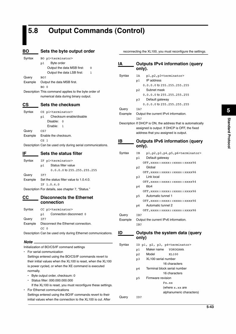
5-43
1
2
3
4
5
6
7
App
Index
Standard Protocol
5.8 Output Commands (Control)
reconnecting the XL100, you must reconfigure the settings.
IA Outputs IPv4 information (query only).
Syntax IA p1,p2,p3<terminator>
p1 IP address 0.0.0.0 to 255.255.255.255p2 Subnet mask 0.0.0.0 to 255.255.255.255p3 Default gateway 0.0.0.0 to 255.255.255.255
Query IA?
Example Output the current IPv4 information. IA?
Description If DHCP is ON, the address that is automatically assigned is output. If DHCP is OFF, the fixed address that you assigned is output.
IB Outputs IPv6 information (query only).
Syntax IB p1,p2,p3,p4,p5,p6<terminator>
p1 Default gateway OFF,xxxx::xxxx::xxxx::xxxx%6
p2 Global OFF,xxxx::xxxx::xxxx::xxxx%6
p3 Link local OFF,xxxx::xxxx::xxxx::xxxx%4
p4 6to4 OFF,xxxx::xxxx::xxxx::xxxx%6
p5 Automatic tunnel 1 OFF,xxxx::xxxx::xxxx::xxxx%6
p6 Automatic tunnel 2 OFF,xxxx::xxxx::xxxx::xxxx%6
Query IB?
Example Output the current IPv6 information. IB?
ID Outputs the system data (query only)
Syntax ID p1, p2, p3, p4<terminator>
p1 Maker name YOKOGAWA
p2 Model XL100
p3 XL100 serial number 16 charactersp4 Terminal block serial number 16 charactersp5 Firmware revision
Fx.xx
(where x.xx are alphanumeric characters)
Query ID?
BO Sets the byte output orderSyntax BO p1<terminator>
p1 Byte order Output the data MSB first: 0
Output the data LSB first: 1
Query BO?
Example Output the data MSB first. BO 0
Description This command applies to the byte order of numerical data during binary output.
CS Sets the checksumSyntax CS p1<terminator>
p1 Checksum enable/disable Disable: 0
Enable: 1
Query CS?
Example Enable the checksum. CS 1
Description Can be used only during serial communications.
IF Sets the status filterSyntax IF p1<terminator>
p1 Status filter value 0.0.0.0 to 255.255.255.255
Query IF?
Example Set the status filter value to 1.0.4.0. IF 1.0.4.0
Description For details, see chapter 7, “Status.”
CC Disconnects the Ethernet connection
Syntax CC p1<terminator>
p1 Connection disconnect 0Query IF?
Example Disconnect the Ethernet connection. CC 0
Description Can be used only during Ethernet communications.
NoteInitialization of BO/CS/IF command settings• For serial communication Settings entered using the BO/CS/IF commands revert to
their initial values when the XL100 is reset, when the XL100 is power cycled, or when the XE command is executed normally.• Byte output order, checksum: 0• Status filter: 000.000.000.000 If the XL100 is reset, you must reconfigure these settings.
• For Ethernet communications Settings entered using the BO/IF commands revert to their
initial values when the connection to the XL100 is cut. After

5-44
Description Parameter p4, the terminal block serial number, is undefined if the terminal block unit is not connected.
IT Outputs terminal block status (query only).
Syntax IT p1<terminator>
p1 Terminal block status When the 8-ch terminal block is connected 0 When the 16-ch terminal block is connected
1
When the terminal block is not connected 3
Query IT?
5.8 Output Commands (Control)
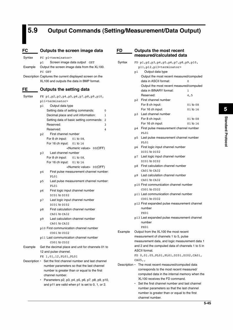
5-45
1
2
3
4
5
6
7
App
Index
Standard Protocol
5.9 Output Commands (Setting/Measurement/Data Output)
FC Outputs the screen image dataSyntax FC p1<terminator>
p1 Screen image data output GET
Example Output the screen image data from the XL100. FC GET
Description Captures the current displayed screen on the XL100 and outputs the data in BMP format.
FE Outputs the setting dataSyntax FE p1,p2,p3,p4,p5,p6,p7,p8,p9,p10,
p11<terminator>
p1 Output data type Setting data of setting commands: 0
Decimal place and unit information: 1
Setting data of basic setting commands: 2 Reserved: 3
Reserved: 4
p2 First channel number For 8 ch input: 01 to 08, For 16 ch input: 01 to 16 <Numeric value> 00(OFF)p3 Last channel number For 8 ch input: 01 to 08, For 16 ch input: 01 to 16 <Numeric value> 00(OFF)p4 First pulse measurement channel number: PL01
p5 Last pulse measurement channel number: PL01
p6 First logic input channel number DI01 to DI02p7 Last logic input channel number DI01 to DI02p8 First calculation channel number CA01 to CA32p9 Last calculation channel number CA01 to CA32p10 First communication channel number CO01 to CO32p11 Last communication channel number CO01 to CO32
Example Get the decimal place and unit for channels 01 to 12 and pulse channel.
FE 1,01,12,PL01,PL01
Description • Set the first channel number and last channel number parameters so that the last channel number is greater than or equal to the first channel number.
• Parameters p2, p3, p4, p5, p6, p7, p8, p9, p10, and p11 are valid when p1 is set to 0, 1, or 2.
FD Outputs the most recent measured/calculated data
Syntax FD p1,p2,p3,p4,p5,p6,p7,p8,p9,p10,
p11,p12,p13<terminator>
p1 Output data type Output the most recent measured/computed
data in ASCII format: 0
Output the most recent measured/computed data in BINARY format: 1
Reserved: 4,5
p2 First channel number For 8 ch input: 01 to 08 For 16 ch input: 01 to 16p3 Last channel number For 8 ch input: 01 to 08 For 16 ch input: 01 to 16p4 First pulse measurement channel number PL01
p5 Last pulse measurement channel number PL01
p6 First logic input channel number DI01 to DI02p7 Last logic input channel number DI01 to DI02p8 First calculation channel number CA01 to CA32p9 Last calculation channel number CA01 to CA32p10 First communication channel number CO01 to CO32p11 Last communication channel number CO01 to CO32p12 First expanded pulse measurement channel
number PX01
p13 Last expanded pulse measurement channel number
PX01
Example Output from the XL100 the most recent measurement of channels 1 to 5, pulse measurement data, and logic measurement data 1 and 2 and the computed data of channels 1 to 5 in ASCII format.
FD 0,01.05,PL01,PL01,DI01,DI02,CA01,
CA05,,
Description • The most recent measured/computed data corresponds to the most recent measured/computed data in the internal memory when the XL100 receives the FD command.
• Set the first channel number and last channel number parameters so that the last channel number is greater than or equal to the first channel number.
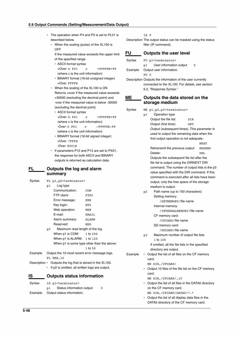
5-46
• The operation when P4 and P5 is set to PL01 is described below.• When the scaling (pulse) of the XL100 is
OFF If the measured value exceeds the upper limit
of the specified range • ASCII format syntax +Over: O P01 c +99999E+99
(where c is the unit information) • BINARY format (16-bit unsigned integer) +Over: FFFFH• When the scaling of the XL100 is ON Returns +over if the measured value exceeds
+30000 (excluding the decimal point) and -over if the measured value is below -30000 (excluding the decimal point).
• ASCII format syntax +Over: O P01 c +99999E+99
(where c is the unit information) -Over: O P01 c -99999E-99
(where c is the unit information) • BINARY format (16-bit signed integer) +Over: 7FFFH -Over: 8001H• If parameters P12 and P13 are set to PX01,
the response for both ASCII and BINARY outputs is returned as calculation data.
FL Outputs the log and alarm summary
Syntax FL p1,p2<terminator>
p1 Log type Communication: COM
FTP client: FTPC
Error message: ERR
Key login: KEY
Web operation: WEB
E-mail: EMAIL
Alarm summary: ALARM Reserved: MSG
p2 Maximum read length of the log When p1 is COM: 1 to 200 When p1 is ALARM: 1 to 120 When p1 is some type other than the above:
1 to 50Example Output the 10 most recent error message logs. FL ERR,10
Description • Outputs the log that is stored in the XL100.• If p2 is omitted, all written logs are output.
IS Outputs status informationSyntax IS p1<terminator>
p1 Status information output 0
Example Output status information.
IS 0
Description The output status can be masked using the status filter (IF command).
FU Outputs the user levelSyntax FU p1<terminator>
p1 User information output 0
Example Output user information. FU 0
Description Outputs the information of the user currently connected to the XL100. For details, see section 6.2, “Response Syntax.”
ME Outputs the data stored on the storage medium
Syntax ME p1,p2,p3<terminator>
p1 Operation type Output the file list: DIR Output (first time): GET
Output (subsequent times). This parameter is used to output the remaining data when the first output operation is not adequate: NEXT
Retransmit the previous output: RESEND Delete: DEL Outputs the subsequent file list after the
file list is output using the DIRNEXT DIR command. The number of output lists is the p3 value specified with the DIR command. If this command is executed after all lists have been output, only the free space of the storage medium is output.
p2 Path name (up to 150 characters) Setting memory: /SETMEMORY/file name Internal memory: /INTERNALMEMORY/file name CF memory card: /CFCARD/file name SD memory card: /SDCARD/file namep3 Maximum number of output file lists 1 to 100 If omitted, all the file lists in the specified
directory are output.Example • Output the list of all files on the CF memory
card. ME DIR,/CFCARD/
• Output 10 files of the file list on the CF memory card.
ME DIR,/CFCARD/,10
• Output the list of all files in the DATA0 directory on the CF memory card.
ME DIR,/CFCARD/DATA0/*.*
• Output the list of all display data files in the DATA0 directory of the CF memory card.
5.9 Output Commands (Setting/Measurement/Data Output)
5-47
1
2
3
4
5
6
7
App
Index
Standard Protocol
ME DIR,/CFCARD/DATA0/*.BMP
• Output the data in the file 72615100.DLO in the DATA0 directory on the CF memory card.
ME GET,/CFCARD/DATA0/72615100.DLO
Description • This command is valid for the specified save destination and load destination medium.
• Parameter p2 is valid when p1 is set to DIR, GET, or DEL.
• Parameter p3 is valid when p1 is set to DIR.• This command can be used to output data over
the communication interface (Ethernet or serial) that was selected with the XO command.
• If an error occurs during data transmission, (p1=) RESEND can be used to retransmit the data.
5.9 Output Commands (Setting/Measurement/Data Output)
5-48
5.10 Output Commands (RS-485 Dedicated Commands)
ESC O Opens the deviceThe ASCII code of ESC is 1BH.See appendix 1, “ASCII Character Codes.”Syntax ESC O p1<terminator>
p1 Device address 01 to 99Example Open the device at address 01, and enable all
commands. ESC O 01
Description • Specifies the address of the device with which to communicate.
• Only one device can be opened at any given time.
• When a device is opened with the ESC O comma d, another device that is currently open is automatically closed.
• When this command is received correctly, the XL100 transmits the data “ESC O ”.
• Normally, either CR+LF or LF can be used as a terminator for communication commands. However, the terminator for this command must be set to CR+LF.
ESC C Closes the deviceThe ASCII code of ESC is 1BH.See appendix 1, “ASCII Character Codes.”Syntax ESC C p1<terminator>
p1 Device address 01 to 99Example Close the device whose address is 01. E C C 01
Description • Clears the current connection with the device.• When this command is received correctly, the
XL100 transmits the data “ESC C ”.• Normally, either CR+LF or LF can be used as
a terminator for communication commands. However, the terminator for this command must be set to CR+LF.
5-49
1
2
3
4
5
6
7
App
Index
Standard Protocol
5.11 Maintenance/Test Commands (Available when using the maintenance/test server function via Ethernet communications)
close Disconnects the connection between other devices
Syntax close,p1,p2:p3<terminator>
p1 Port on the XL100 side 0 to 65535p2 IP address on the PC side 0.0.0.0 to 255.255.255.255p3 Port on the PC side 0 to 65535
Example close,349,192.168.111.24:1054
E0
Description This command cannot be used to disconnect a server port. Also, it cannot disconnect the XL100 being operated. Use the quit command for this purpose.
con Outputs connection informationSyntax con<terminator>
Example con
EA
00/00/00 12:34:56
Active connections
Proto Local Address Foreign Address
State
TCP 192.168.111. 24:34159
192.168.111. 24:1053 ESTABLISHED
TCP 0. 0. 0. 0:34155 0. 0. 0. 0: 0
LISTEN
TCP 0. 0. 0. 0:34159 0. 0. 0. 0: 0
LISTEN
TCP 0. 0. 0. 0:34150 0. 0. 0. 0: 0
LISTEN
EN
TCP: Protocol usedLocal Address: The XL100 socket address.
Displays “IP address:port number”Foreign Address: The destination socket address.
Displays “IP address:port number”State: Connection statusESTABLISHED: Connection established
eth Outputs Ethernet statistical information
Syntax eth<terminator>Example
eth
EA
00/00/00 12:34:56
Ethernet Statistics
Name In Pkt In Err Out Pkt Out Err 16
Coll
lo0 0 0 0 0 0
mb0 74 0 64 0 0
EN
help Outputs helpSyntax help [,p1]<terminator>
p1 Command name(close, con, eth, help, net, quit)
Example help
EA
con - echo connection information
eth - echo ethernet information
help - echo help
net - echo network status
quit - close this connection
EN
net Outputs network statistical information
Syntax net<terminator>Example
net
EA
05/12/08 15:37:12
Network Status
TCP6 Statistics:
--------------
Active Opens = 0
Passive Opens = 0
Connect Attempt Fails = 0
Reset Connections = 0
Current Connections = 0
Segments Received = 0
Segments Sent = 0
Segments Retransmitted = 0
Errors Received = 0
Sgmnts sent w/Reset Flag = 0
Cumulative Connections = 4
Time-Out Algorithm = 4
Time-Out Minimim = 300
Time-Out Maximum = 240000
MaximumConnections=Dynamic(-1)
TCP Statistics:
--------------
Active Opens = 0
Passive Opens = 59
Connect Attempt Fails = 0
5-50
Reset Connections = 4
Current Connections = 1
Segments Received = 910
Segments Sent = 1155
Segments Retransmitted = 1
Errors Received = 0
Sgmnts sent w/Reset Flag = 7
Cumulative Connections = 7
Time-Out Algorithm = 4
Time-Out Minimim = 300
Time-Out Maximum = 120000
MaximumConnections=Dynamic(-1)
UDP6 Statistics:
--------------
Datagrams Received = 0
No Ports = 0
Receive Errors = 0
Datagrams Sent = 0
Number UDP entries = 1
UDP Statistics:
Datagrams Received = 3806
No Ports = 131684
Receive Errors = 0
Datagrams Sent = 77
Number UDP entries = 2
IP6 Statistics:
--------------
Packets Received = 0
Received Header Errors = 0
Received Address Errors = 0
Datagrams Forwarded = 0
Unknown Protocols Received = 0
Received Packets Discarded = 0
Received Packets Delivered = 0
Output Requests = 0
Routing Discards = 0
Discarded Output Packets = 0
Output Packet No Route = 0
Reassembly Required = 0
Reassembly Successful = 0
Reassembly Failures = 0
Datagrams Fragmented OK = 0
Datagrams Fragmented Fail = 0
Fragments Created = 0
DefaultTTL = 128
Datagrams All Frgs Not Rcvd = 120
Number of Interfaces = 5
Number of Addresses = 4
Number of Routes in Table = 0
Forwarding Enabled = 2
IP Statistics:
--------------
Packets Received = 272870
Received Header Errors = 0
Received Address Errors = 446
Datagrams Forwarded = 0
Unknown Protocols Received = 0
Received Packets Discarded = 0
Received Packets Delivered = 136402
Output Requests = 1236
Routing Discards = 0
Discarded Output Packets = 0
Output Packet No Route = 0
Reassembly Required = 0
Reassembly Successful = 0
Reassembly Failures = 0
Datagrams Fragmented OK = 0
Datagrams Fragmented Fail = 0
Fragments Created = 0
DefaultTTL = 128
Datagrams All Frgs Not Rcvd = 60
Number of Interfaces = 2
Number of Addresses = 2
Number of Routes in Table = 7
Forwarding Enabled = 2
ICMP6 Statistics Received Sent
---------- ------ ------
Messages 0 87
Errors 0 0
Destination Unreachable
0 0
Packet Too Big 0 0
Time Exceeded 0 0
Param Problem 0 0
Echo Request 0 0
Echo Reply 0 0
Membership Query 0 0
Membership report 0 29
Membership reduction
0 0
Router Solicitation 0 43
Router Advertisment 0 0
Neighbor Solicitation
0 15
Neighbor Advertisment
0 0
Redirect 0 0
ICMP Statistics Received
Sent
Messages 2 4
Errors 0 1
Destination Unreachable
0 1
Time Exceeded 0 0
Parmeter Problems 0 0
Source Quenches 0 0
Redirects 0 0
Echos 2 0
5.11 Maintenance/Test Commands
5-51
1
2
3
4
5
6
7
App
Index
Standard Protocol
Echo Replies 0 2
Timestamps 0 0
Timestamp Replies 0 0
Address Masks 0 0
Address Mask Replies
0 0
EN
Description TCP6 Statistics: This section displays the statistics related to
TCP (bidirectional communication protocol for achieving reliable stream communication) of IPv6.
TCP Statistics: This section displays the statistics related to
TCP (bidirectional communication protocol for achieving reliable stream communication) of IPv4.
Active Opens: The total number of connections opened
actively. This is the number of times the connection requested from the XL100 to the external server standing by that was established.
Passive Opens: The total number of connections opened
passively. This is the number of times the XL100, the server, accepted the connection request from the outside.
Connect Attempt Fails: The number of times the connection request
failed.Reset Connections: The number of times the connection was
rejected in the middle.Current Connections: The total number of TCP connections
currently active.Segments Receive: The total number of received segments.Segments Sent: The total number of transmitted segments.Segments Retransmitted: The total number of segments that were
retransmitted when receive acknowledge was not returned from the peer.
Errors Received: The total number of received segments with
errors.Sgmnts sent w/Reset Flag: The total number of transmitted segments with
a reset flag.Cumulative Connections: The cumulative number of connections.Time-Out Algorithm:
The timeout algorithm type.Time-Out Minimim: The minimum timeout value for
retransmission.Time-Out Maximum: The maximum timeout value for
retransmission.Maximum Connections: The maximum number of connections.UDP6 Statistics: This section displays the statistics related to
UDP (unreliable datagram communication protocol) of IPv6.
UDP Statistics: This section displays the statistics related to
UDP (unreliable datagram communication protocol) of IPv4.
Datagrams Received: The total number of received UDP packets.No Ports: The total number of received packets without
the service (program) that the UDP packet contains.
Receive Errors: The total number of UDP packets that could
not be delivered to the higher level service due to an error or another reason.
Datagrams Sent: The total number of transmitted UDP packets.Number UDP entries: The total number of entries in the UDP listener
table.IP6 Statistics: This section displays various statistics related
to the IPv6 protocol.IP4 Statistics: This section displays various statistics related
to the IPv4 protocol.Packets Received: The total number of IP packets received from
all network interfaces.Received Header Errors: The total number of IP packets that were
discarded due to some error in the IP header such as a checksum error or an incorrect version number.
Received Address Errors: The total number of IP packets that were
discarded due to an invalid destination IP address (such as 0.0.0.0).
Datagrams Forwarded: The total number of IP packets that were
forwarded (routed to another interface) on the machine operating as a router.
Unknown Protocols Received:
5.11 Maintenance/Test Commands
5-52
The total number of IP packets with an undefined higher level protocol (invalid number) in the IP header.
Received Packets Discarded: The total number of IP packets that were
received but were discarded or rejected due to insufficient buffer area, a firewall function (OS-embedded), etc.
Received Packets Delivered: The total number of IP packets that were sent
to a higher level protocol stack such as ICMP, TCP, or UDP.
Output Requests: The total number of IP packets sent externally.Routing Discards: The total number of IP packets that were
discarded, because the packets could not be routed such as due to a configuration error in the routing table.
Discarded Output Packets: The total number of IP packets that were
discarded without being sent or rejected due to insufficient buffer area or a block provided by a firewall function (OS-embedded), etc.
Output Packet No Route: The total number of IP packets that were
discarded, because the packets could not be routed such as due to an undefined destination.
Reassembly Required: The total number of received fragmented
packets (incomplete IP packets).Reassembly Successful: The number of times the reassembly of
fragments were successful. In other words, this is the total number of complete IP packets that were reassembled from fragments.
Reassembly Failures: The total number of fragment reassembly
failures such as due to a timeout (all the fragments were not collected within a given time) or insufficient resource.
Datagrams Fragmented OK: The total number of transmission IP
packets that were fragmented at the time of transmission.
Datagrams Fragmented Fail: The total number of transmission IP packets
that failed in the fragmentation.Fragments Created: The total number of fragmented packets
created by fragmenting the transmission IP packet.
DefaultTTL: The default TTL (Time To Live) of transmission
IP packets.Datagrams All Frgs Not Rcvd:
The number of IP packets whose fragmented packets could not be received in whole.
Number of Interfaces: The number of interfaces.Number of Addresses: The number of addresses related to the
XL100.Number of Routes in Table: The number of routes in the routing
table (routing information of the packet’s destination) of the XL100.
Forwarding Enabled: Enabled/Disabled state of IP forwardingICMP6 Statistics: This section displays statistics related to the
ICMP6 protocol of IPv6.ICMP Statistics: This section displays statistics related to the
ICMP protocol.Messages: The total number of sent and received ICMP
packets.Errors: The total number of ICMP packets with errors
such as incorrect code or invalid checksum.Destination Unreachable: The total number of ICMP message packets
that could not be sent to the destination.Packet Too Big: The total number of ICMP message packets
that were too big.Time Exceeded: The total number of ICMP message packets in
which the TTL (Time To Live) that determines the maximum number of hops became 0 in the middle of routing.
Parameter Problems: The total number of ICMP message packets in
which the ICMP message parameter is invalid.Source Quenches: The total number of ICMP message packets
that are sent to control the transmission, because the receiver resource has run out or is about to run out.
Echos: The total number of ICMP message packets
of ICMP Echo (command sent from the sender of ping).
Echo Replies: The total number of ICMP message packets
of ICMP Echo Reply (command returned from the receiver of ping).
Timestamps: The total number of ICMP message packets
of Timestamp Request.Timestamp Replies:
5.11 Maintenance/Test Commands
5-53
1
2
3
4
5
6
7
App
Index
Standard Protocol
The total number of ICMP message packets in response to Timestamp Request.
Address Masks: The total number of ICMP message packets
of Address Mask Request.Address Mask Replies: The total number of ICMP message packets in
response to Address Mask Request.Redirects: The total number of ICMP message packets
of Redirect (redirect because a better route exists).
Membership Query: The total number of ICMPV6 message
packets of Membership Query.Membership report: The total number of ICMPV6 message
packets of Membership Report in response to Membership Request.
Membership reduction: The total number of ICMPV6 message
packets of Membership Reduction.Router Solicitation: The total number of ICMPV6 Router
Solicitation message packets.Router Advertisement: The total number of ICMPV6 Router
Advertisement message packets.Neighbor Solicitation: The total number of ICMPV6 Neighbor
Solicitation message packets.Neighbor Advertisement: The total number of ICMPV6 Neighbor
Advertisement message packets.
quit Disconnects the connection of the device being operated
Syntax quit<terminator>
5.11 Maintenance/Test Commands
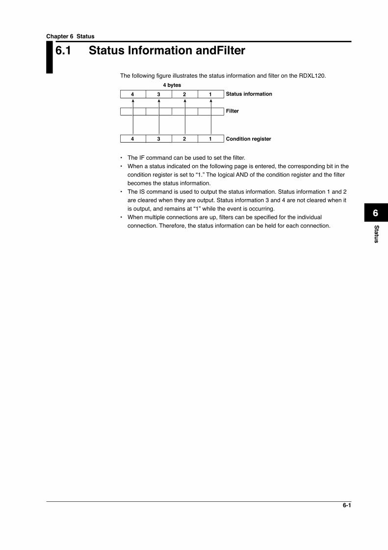
6-1
1
2
3
4
5
6
7
App
Index
Status
6.1 Status Information andFilter
The following figure illustrates the status information and filter on the RDXL120.
Status information
Filter
Condition register
4 bytes4 3 2 1
4 3 2 1
• The IF command can be used to set the filter.• When a status indicated on the following page is entered, the corresponding bit in the
condition register is set to “1.” The logical AND of the condition register and the filter becomes the status information.
• The IS command is used to output the status information. Status information 1 and 2 are cleared when they are output. Status information 3 and 4 are not cleared when it is output, and remains at “1” while the event is occurring.
• When multiple connections are up, filters can be specified for the individual connection. Therefore, the status information can be held for each connection.
Chapter 6 Status
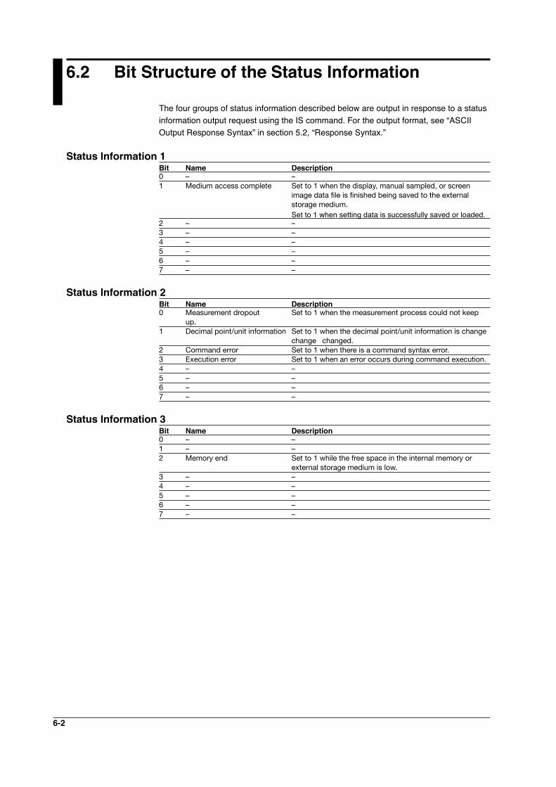
6-2
6.2 Bit Structure of the Status Information
The four groups of status information described below are output in response to a status information output request using the IS command. For the output format, see “ASCII Output Response Syntax” in section 5.2, “Response Syntax.”
Status Information 1Bit Name Description0 – –1 Medium access complete Set to 1 when the display, manual sampled, or screen
image data file is finished being saved to the external storage medium.
Set to 1 when setting data is successfully saved or loaded.2 – –3 – –4 – –5 – –6 – – 7 – –
Status Information 2Bit Name Description0 Measurement dropout Set to 1 when the measurement process could not keep
up.1 Decimal point/unit information Set to 1 when the decimal point/unit information is change
change changed.2 Command error Set to 1 when there is a command syntax error.3 Execution error Set to 1 when an error occurs during command execution.4 – –5 – –6 – –7 – –
Status Information 3Bit Name Description0 – –1 – –2 Memory end Set to 1 while the free space in the internal memory or
external storage medium is low.3 – –4 – – 5 – – 6 – –7 – –
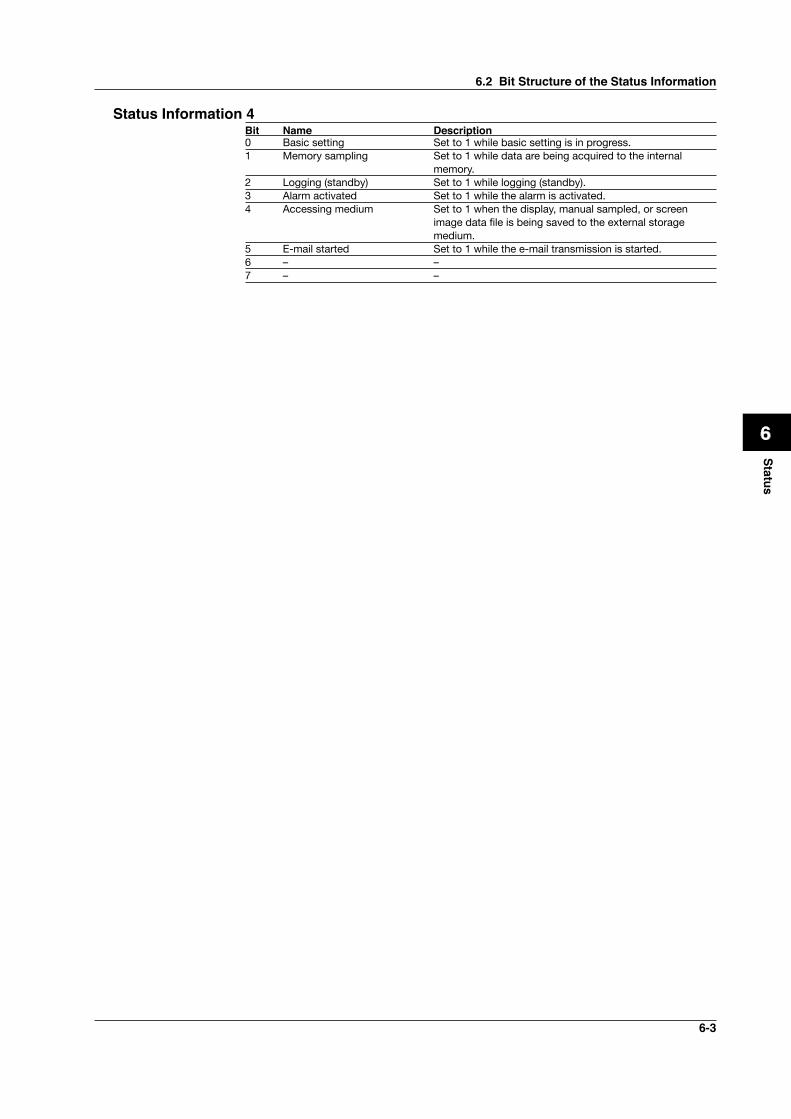
6-3
1
2
3
4
5
6
7
App
Index
Status
Status Information 4Bit Name Description0 Basic setting Set to 1 while basic setting is in progress.1 Memory sampling Set to 1 while data are being acquired to the internal
memory.2 Logging (standby) Set to 1 while logging (standby).3 Alarm activated Set to 1 while the alarm is activated.4 Accessing medium Set to 1 when the display, manual sampled, or screen
image data file is being saved to the external storage medium.
5 E-mail started Set to 1 while the e-mail transmission is started.6 – –7 – –
6.2 Bit Structure of the Status Information
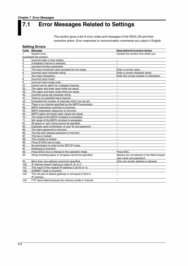
7-1
7.1 Error Messages Related to Settings
This section gives a list of error codes and messages of the RDXL120 and their corrective action. Error responses to communication commands are output in English.
Setting ErrorsCode Message Description/Corrective Action1 System error. Contact the vendor from which you purchased the product.2 Incorrect date or time setting. – 3 A disabled channel is selected. – 4 Incorrect function parameter. – 5 The input numerical value exceeds the set range. Enter a correct value.6 Incorrect input character string. Enter a correct character string.7 Too many characters. Enter the correct number of characters.8 Incorrect input mode. – 9 Incorrect input range code. – 21 Cannot set an alarm for a skipped channel. – 22 The upper and lower span limits are equal. – 22 The upper and lower scale limits are equal. –40 Incorrect group set character string. –41 There is no specified input channel. –42 Exceeded the number of channels which can be set. – 61 There is no channel specified by the MATH expression. – 62 MATH expression grammar is incorrect. – 63 MATH expression sequence is incorrect. – 64 MATH upper and lower span values are equal. – 70 The range of the MATH constant is exceeded. – 71 Set range of the MATH constant is exceeded. – 81 All space or ‘quit’ string cannot be specified. – 83 Duplicate used combination of user ID and password. – 85 The login password is incorrect. – 86 The key-lock release password is incorrect. –87 This key is locked. –88 This function is locked. –89 Press [FUNC] key to login. –90 No permission to enter to the SETUP mode. –91 Password is incorrect. –92 Press [ESC] key to change to the operation mode. Press ESC.93 String including space or all space cannot be specified. Spaces are not allowed in the Web browser user name and password.94 More than one address cannot be specified. Only one sender address is allowed.100 IP address doesn’t belong to class A, B, or C. –101 The result of the masked IP address is all 0s or 1s. –102 SUBNET mask is incorrect. – 103 The net part of default gateway is not equal to that of – IP address. 104 FTP client failed because the memory mode is ‘manual’. –
Chapter 7 Error Messages
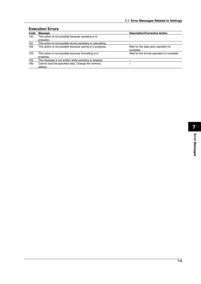
7-2
1
2
3
4
5
6
7
App
Index
Error Messages
Execution ErrorsCode Message Description/Corrective Action150 This action is not possible because sampling is in – progress. 151 This action is not possible during sampling or calculating. –152 This action is not possible because saving is in progress. Wait for the data save operation to complete.153 This action is not possible because formatting is in Wait for the format operation to complete. progress. 155 The message is not written while sampling is stopped. –160 Cannot load the specified data. Change the memory – setting.
7.1 Error Messages Related to Settings
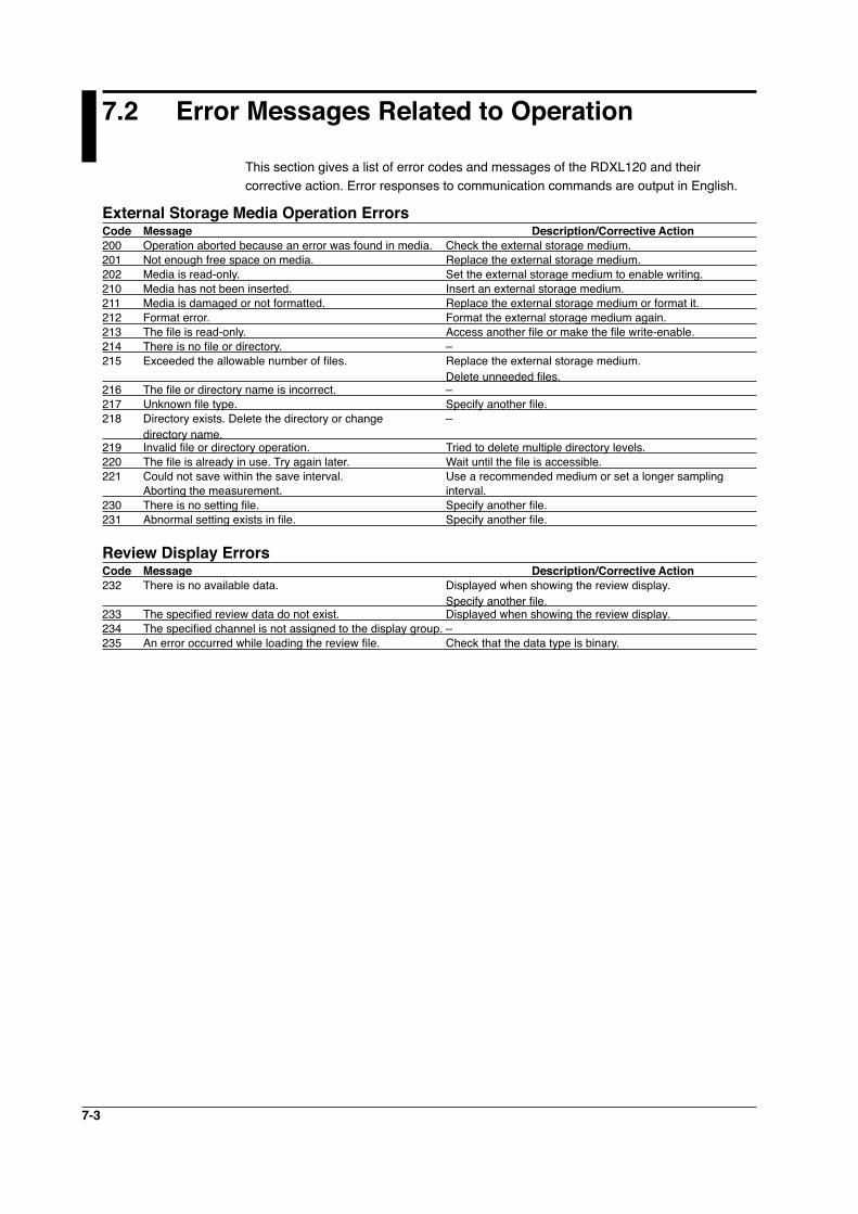
7-3
7.2 Error Messages Related to Operation
This section gives a list of error codes and messages of the RDXL120 and their corrective action. Error responses to communication commands are output in English.
External Storage Media Operation ErrorsCode Message Description/Corrective Action200 Operation aborted because an error was found in media. Check the external storage medium. 201 Not enough free space on media. Replace the external storage medium.202 Media is read-only. Set the external storage medium to enable writing.210 Media has not been inserted. Insert an external storage medium.211 Media is damaged or not formatted. Replace the external storage medium or format it.212 Format error. Format the external storage medium again.213 The file is read-only. Access another file or make the file write-enable.214 There is no file or directory. –215 Exceeded the allowable number of files. Replace the external storage medium. Delete unneeded files.216 The file or directory name is incorrect. –217 Unknown file type. Specify another file.218 Directory exists. Delete the directory or change – directory name. 219 Invalid file or directory operation. Tried to delete multiple directory levels. 220 The file is already in use. Try again later. Wait until the file is accessible.221 Could not save within the save interval. Use a recommended medium or set a longer sampling Aborting the measurement. interval.230 There is no setting file. Specify another file.231 Abnormal setting exists in file. Specify another file.
Review Display ErrorsCode Message Description/Corrective Action232 There is no available data. Displayed when showing the review display. Specify another file.233 The specified review data do not exist. Displayed when showing the review display. 234 The specified channel is not assigned to the display group. – 235 An error occurred while loading the review file. Check that the data type is binary.
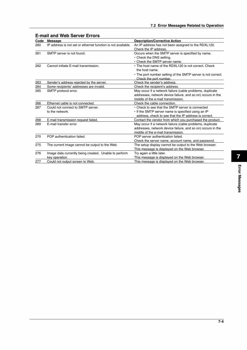
7-4
1
2
3
4
5
6
7
App
Index
Error Messages
E-mail and Web Server ErrorsCode Message Description/Corrective Action260 IP address is not set or ethernet function is not available. An IP address has not been assigned to the RDXL120. Check the IP address.261 SMTP server is not found. Occurs when the SMTP server is specified by name. • Check the DNS setting. • Check the SMTP server name.262 Cannot initiate E-mail transmission. • The host name of the RDXL120 is not correct. Check the host name. • The port number setting of the SMTP server is not correct. Check the port number.263 Sender’s address rejected by the server. Check the sender’s address. 264 Some recipients’ addresses are invalid. Check the recipient’s address. 265 SMTP protocol error. May occur if a network failure (cable problems, duplicate addresses, network device failure, and so on) occurs in the middle of the e-mail transmission. 266 Ethernet cable is not connected. Check the cable connection. 267 Could not connect to SMTP server. • Check to see that the SMTP server is connected to the network. • If the SMTP server name is specified using an IP address, check to see that the IP address is correct.268 E-mail transmission request failed. Contact the vendor from which you purchased the product.269 E-mail transfer error. May occur if a network failure (cable problems, duplicate addresses, network device failure, and so on) occurs in the middle of the e-mail transmission. 270 POP authentication failed. POP server authentication failed. Check the server name, account name, and password.275 The current image cannot be output to the Web. The setup display cannot be output to the Web browser. This message is displayed on the Web browser.276 Image data currently being created. Unable to perform Try again a little later. key operation. This message is displayed on the Web browser.277 Could not output screen to Web. This message is displayed on the Web browser.
7.2 Error Messages Related to Operation
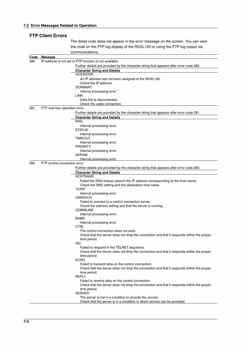
7-5
FTP Client ErrorsThe detail code does not appear in the error message on the screen. You can view the code on the FTP log display of the RDXL120 or using the FTP log output via communications.
Code Message280 IP address is not set or FTP function is not available. Further details are provided by the character string that appears after error code 280. Character String and Details HOSTADDR An IP address has not been assigned to the RDXL120. Check the IP address. DORMANT Internal processing error.*1 LINK Data link is disconnected. Check the cable connection.281 FTP mail box operation error. Further details are provided by the character string that appears after error code 281. Character String and Details MAIL Internal processing error. STATUS Internal processing error. TIMEOUT Internal processing error. PRIORITY Internal processing error. NVRAM Internal processing error.282 FTP control connection error. Further details are provided by the character string that appears after error code 282. Character String and Details HOSTNAME Failed the DNS lookup (search the IP address corresponding to the host name). Check the DNS setting and the destination host name. TCPIP Internal processing error. UNREACH Failed to connect to a control connection server. Check the address setting and that the server is running. OOBINLINE Internal processing error. NAME Internal processing error. CTRL The control connection does not exist. Check that the server does not drop the connection and that it responds within the proper time period. IAC Failed to respond in the TELNET sequence. Check that the server does not drop the connection and that it responds within the proper time period. ECHO Failed to transmit data on the control connection. Check that the server does not drop the connection and that it responds within the proper time period. REPLY Failed to receive data on the control connection. Check that the server does not drop the connection and that it responds within the proper time period. SERVER The server is not in a condition to provide the service. Check that the server is in a condition in which service can be provided.
7.2 Error Messages Related to Operation
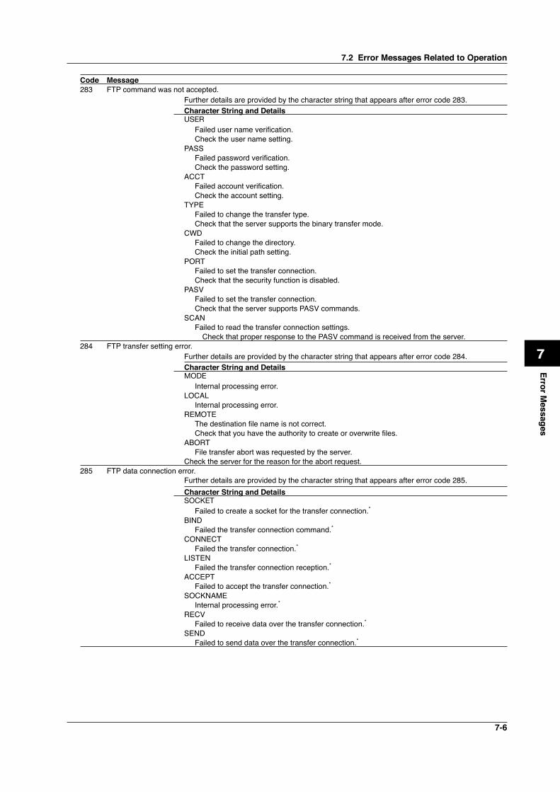
7-6
1
2
3
4
5
6
7
App
Index
Error Messages
Code Message283 FTP command was not accepted. Further details are provided by the character string that appears after error code 283. Character String and Details USER Failed user name verification. Check the user name setting. PASS Failed password verification. Check the password setting. ACCT Failed account verification. Check the account setting. TYPE Failed to change the transfer type. Check that the server supports the binary transfer mode. CWD Failed to change the directory. Check the initial path setting. PORT Failed to set the transfer connection. Check that the security function is disabled. PASV Failed to set the transfer connection. Check that the server supports PASV commands. SCAN Failed to read the transfer connection settings. Check that proper response to the PASV command is received from the server.284 FTP transfer setting error. Further details are provided by the character string that appears after error code 284. Character String and Details MODE Internal processing error. LOCAL Internal processing error. REMOTE The destination file name is not correct. Check that you have the authority to create or overwrite files. ABORT File transfer abort was requested by the server. Check the server for the reason for the abort request.285 FTP data connection error. Further details are provided by the character string that appears after error code 285. Character String and Details SOCKET Failed to create a socket for the transfer connection.* BIND Failed the transfer connection command.* CONNECT Failed the transfer connection.* LISTEN Failed the transfer connection reception.* ACCEPT Failed to accept the transfer connection.* SOCKNAME Internal processing error.* RECV Failed to receive data over the transfer connection.* SEND Failed to send data over the transfer connection.*
7.2 Error Messages Related to Operation

7-7
Code Message286 FTP file transfer error. Further details are provided by the character string that appears after error code 286. Character String and Details READ Internal processing error. WRITE Internal processing error.
* These errors may occur if the network experiences trouble during the data transmission (bad cable connection, duplicate addresses, network equipment failure).
Note If the server does not respond within this time period, the transfer fails.
7.2 Error Messages Related to Operation
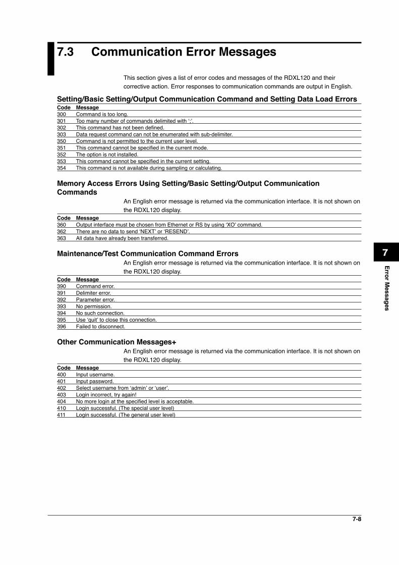
7-8
1
2
3
4
5
6
7
App
Index
Error Messages
7.3 Communication Error Messages
This section gives a list of error codes and messages of the RDXL120 and their corrective action. Error responses to communication commands are output in English.
Setting/Basic Setting/Output Communication Command and Setting Data Load ErrorsCode Message300 Command is too long. 301 Too many number of commands delimited with ‘;’.302 This command has not been defined.303 Data request command can not be enumerated with sub-delimiter.350 Command is not permitted to the current user level.351 This command cannot be specified in the current mode.352 The option is not installed.353 This command cannot be specified in the current setting.354 This command is not available during sampling or calculating.
Memory Access Errors Using Setting/Basic Setting/Output Communication Commands
An English error message is returned via the communication interface. It is not shown on the RDXL120 display.
Code Message360 Output interface must be chosen from Ethernet or RS by using ‘XO’ command.362 There are no data to send ‘NEXT’ or ‘RESEND’.363 All data have already been transferred.
Maintenance/Test Communication Command ErrorsAn English error message is returned via the communication interface. It is not shown on the RDXL120 display.
Code Message390 Command error.391 Delimiter error.392 Parameter error.393 No permission.394 No such connection.395 Use ‘quit’ to close this connection.396 Failed to disconnect.
Other Communication Messages+An English error message is returned via the communication interface. It is not shown on the RDXL120 display.
Code Message400 Input username.401 Input password.402 Select username from ‘admin’ or ‘user’.403 Login incorrect, try again!404 No more login at the specified level is acceptable.410 Login successful. (The special user level)411 Login successful. (The general user level)

7-9
Code Message420 Connection has been lost.421 The number of simultaneous connection has been exceeded.422 Communication has timed-out.
ModBus Master Error LogAn English error message is returned via the communication interface. It is not shown on the RDXL120 display.
Code Message700 Data could not be received within communication loop time.701 Connection to some slave is suspended.702 Connection to slave(s) has recovered.
7.3 Communication Error Messages

App-1
1
2
3
4
5
6
7
App
Index
Appendix
Appendix 1 ASCII Character Codes
0
1
2
3
4
5
6
7
8
9
A
B
C
D
E
F
0
LF
CR
1
ESC
2
SP
!
#
%
&
(
)
*
+
–
.
/
3
0
1
2
3
4
5
6
7
8
9
:
=
?
4
@
A
B
C
D
E
F
G
H
I
J
K
L
M
N
O
5
P
Q
R
S
T
U
V
W
X
Y
Z
[
\
]
•
_
6
a
b
c
d
e
f
g
h
i
j
k
l
m
n
o
7
p
q
r
s
t
u
v
w
x
y
z
~
8 9 A B C D E F
Upper 4 bits
Low
er 4
bits
• Backslashes can be used only to enter the initial path parameter of the FTP client.• Colons can be used only to enter the server name parameter of an SNTP server,
SMTP server, and FTP server.
Appendix
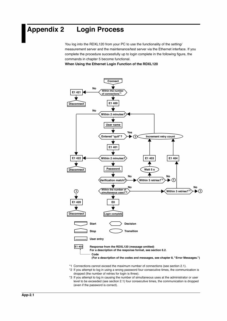
App-2.1
Appendix 2 Login Process
You log into the RDXL120 from your PC to use the functionality of the setting/measurement server and the maintenance/test server via the Ethernet interface. If you complete the procedure successfully up to login complete in the following figure, the commands in chapter 5 become functional.When Using the Ethernet Login Function of the RDXL120
E1 403
E1 403
Yes
No
No
No
No No
No
E1 404
E1 421
Connect
Disconnect
E1 422
Disconnect
E1 420
Disconnect Login complete
Within 3 retries?*2
Within 3 retries?*3
Wait 5 s
E1 401
E0
E1 400
Entered "quit"?
Verification match?
Within the number of simultaneous uses?*3
Within 2 minutes?
Within the number of connections*1
Within 2 minutes?
User name
Password
Increment retry count
1
1
1
1
Stop
Start Decision
Transition
Code(For a description of the codes and messages, see chapter 8, "Error Messages.")
Response from the RDXL120 (message omitted)For a description of the response format, see section 6.2.
User entry
*1 Connections cannot exceed the maximum number of connections (see section 2.1).*2 If you attempt to log in using a wrong password four consecutive times, the communication is
dropped (the number of retries for login is three).*3 If you attempt to log in causing the number of simultaneous uses at the administrator or user
level to be exceeded (see section 2.1) four consecutive times, the communication is dropped (even if the password is correct).
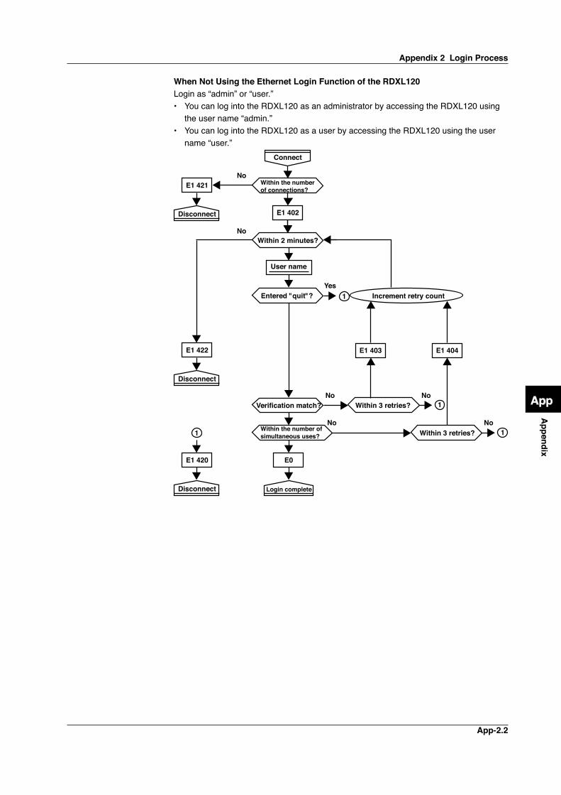
App-2.2
1
2
3
4
5
6
7
App
Index
Appendix
When Not Using the Ethernet Login Function of the RDXL120Login as “admin” or “user.”• You can log into the RDXL120 as an administrator by accessing the RDXL120 using
the user name “admin.”• You can log into the RDXL120 as a user by accessing the RDXL120 using the user
name “user.”
E1 403
Yes
No
No
No
No No
No
E1 404
E1 421
Connect
Disconnect
E1 422
Disconnect
E1 420
Disconnect Login complete
Within 3 retries?
Within 3 retries?
E0
E1 402
Entered "quit"?
Verification match?
Within the number of simultaneous uses?
Within the number of connections?
Within 2 minutes?
User name
Increment retry count
1
1
1
1
Appendix 2 Login Process
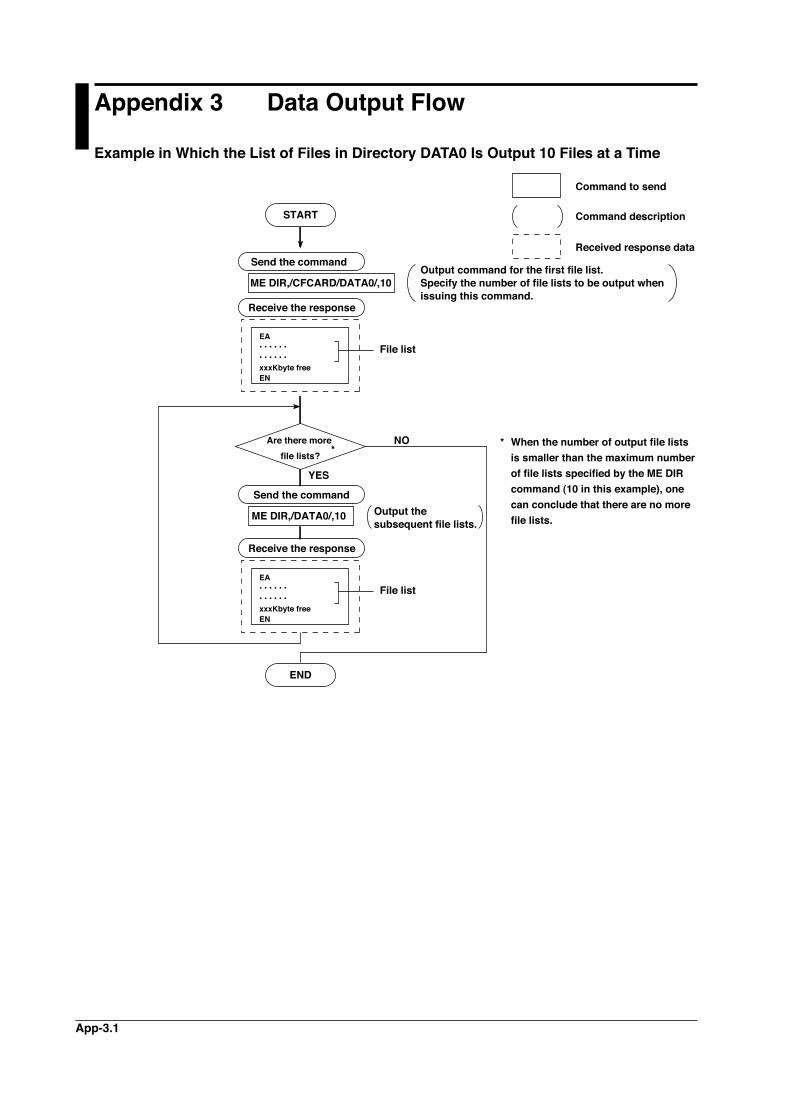
App-3.1
Appendix 3 Data Output Flow
Example in Which the List of Files in Directory DATA0 Is Output 10 Files at a Time
ME DIR,/CFCARD/DATA0/,10
NO
START
YES
END
Send the command
Are there more file lists?
Receive the response
ME DIR,/DATA0/,10
*
Send the command
Receive the response
* When the number of output file lists is smaller than the maximum number of file lists specified by the ME DIR command (10 in this example), one can conclude that there are no more file lists.
Output command for the first file list.Specify the number of file lists to be output when issuing this command.
Command description
Command to send
Received response data
Output the subsequent file lists.
EA• • • • • •• • • • • •xxxKbyte freeEN
File list
EA• • • • • •• • • • • •xxxKbyte freeEN
File list
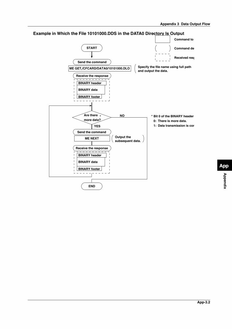
App-3.2
1
2
3
4
5
6
7
App
Index
Appendix
Example in Which the File 10101000.DDS in the DATA0 Directory Is Output
ME GET,/CFCARD/DATA0/10101000.DLO
NO
START
YES
END
Send the command
Are there more data?
Receive the response
BINARY header
BINARY data
BINARY footer
ME NEXT
*
Send the command
BINARY header
BINARY data
BINARY footer
Receive the response
* Bit 0 of the BINARY header flag 0: There is more data. 1: Data transmission is complete.
Specify the file name using full pathand output the data.
Command description
Command to send
Received response data
Output the subsequent data.
Appendix 3 Data Output Flow
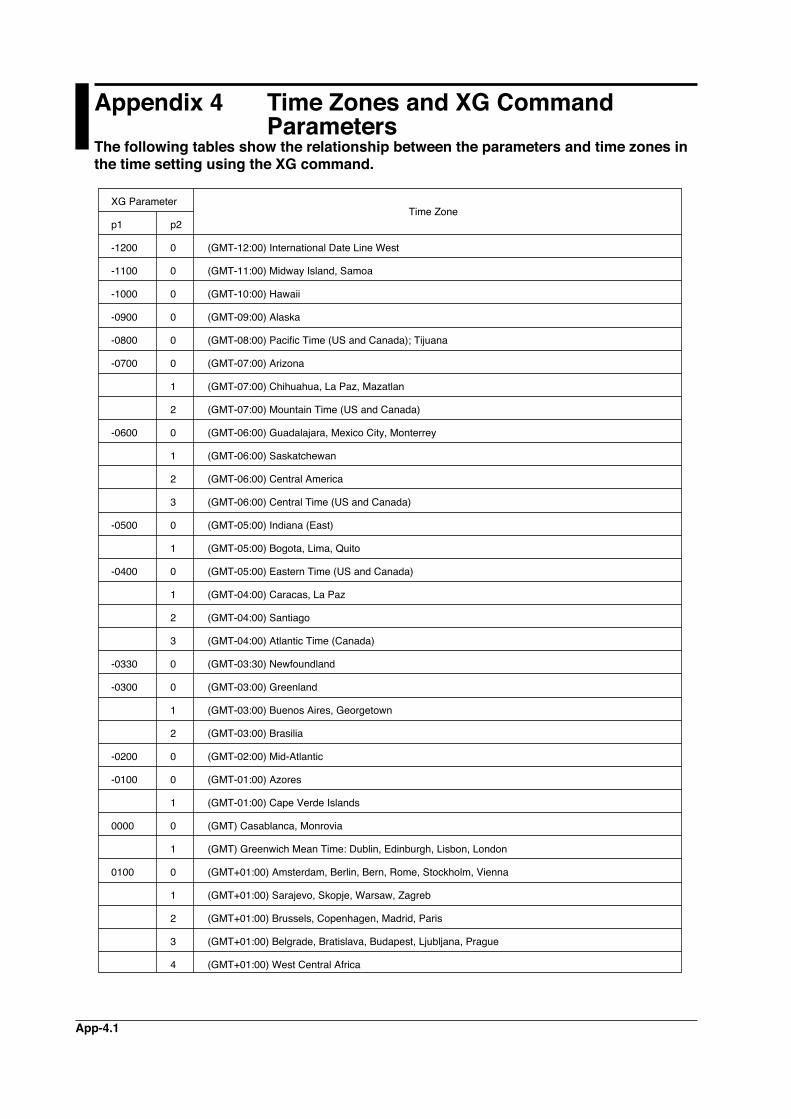
App-4.1
Appendix 4 Time Zones and XG Command Parameters The following tables show the relationship between the parameters and time zones in the time setting using the XG command.
XG Parameter
p1 p2
-1200 0 (GMT-12:00) International Date Line West
-1100 0 (GMT-11:00) Midway Island, Samoa
-1000 0 (GMT-10:00) Hawaii
-0900 0 (GMT-09:00) Alaska
-0800 0 (GMT-08:00) Pacific Time (US and Canada); Tijuana
-0700 0 (GMT-07:00) Arizona
1 (GMT-07:00) Chihuahua, La Paz, Mazatlan
2 (GMT-07:00) Mountain Time (US and Canada)
-0600 0 (GMT-06:00) Guadalajara, Mexico City, Monterrey
1 (GMT-06:00) Saskatchewan
2 (GMT-06:00) Central America
3 (GMT-06:00) Central Time (US and Canada)
-0500 0 (GMT-05:00) Indiana (East)
1 (GMT-05:00) Bogota, Lima, Quito
-0400 0 (GMT-05:00) Eastern Time (US and Canada)
1 (GMT-04:00) Caracas, La Paz
2 (GMT-04:00) Santiago
3 (GMT-04:00) Atlantic Time (Canada)
-0330 0 (GMT-03:30) Newfoundland
-0300 0 (GMT-03:00) Greenland
1 (GMT-03:00) Buenos Aires, Georgetown
2 (GMT-03:00) Brasilia
-0200 0 (GMT-02:00) Mid-Atlantic
-0100 0 (GMT-01:00) Azores
1 (GMT-01:00) Cape Verde Islands
0000 0 (GMT) Casablanca, Monrovia
1 (GMT) Greenwich Mean Time: Dublin, Edinburgh, Lisbon, London
0100 0 (GMT+01:00) Amsterdam, Berlin, Bern, Rome, Stockholm, Vienna
1 (GMT+01:00) Sarajevo, Skopje, Warsaw, Zagreb
2 (GMT+01:00) Brussels, Copenhagen, Madrid, Paris
3 (GMT+01:00) Belgrade, Bratislava, Budapest, Ljubljana, Prague
4 (GMT+01:00) West Central Africa
Time Zone
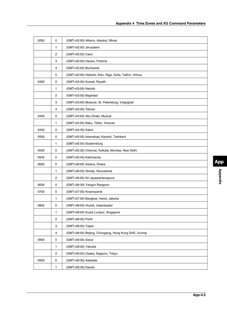
App-4.2
1
2
3
4
5
6
7
App
Index
Appendix
0200 0
1
2
3
4
5
0300 0
1
2
3
4
0400 0
1
0430 0
0500 0
1
0530 0
0545 0
0600 0
1
2
0630 0
0700 0
1
0800 0
1
2
3
4
0900 0
1
2
0930 0
1
(GMT+02:00) Athens, Istanbul, Minsk
(GMT+02:00) Jerusalem
(GMT+02:00) Cairo
(GMT+02:00) Harare, Pretoria
(GMT+02:00) Bucharest
(GMT+02:00) Helsinki, Kiev, Riga, Sofia, Tallinn, Vilnius
(GMT+03:00) Kuwait, Riyadh
(GMT+03:00) Nairobi
(GMT+03:00) Baghdad
(GMT+03:00) Moscow, St. Petersburg, Volgograd
(GMT+03:00) Tehran
(GMT+04:00) Abu Dhabi, Muscat
(GMT+04:00) Baku, Tbilisi, Yerevan
(GMT+04:30) Kabul
(GMT+05:00) Islamabad, Karachi, Tashkent
(GMT+05:00) Ekaterinburg
(GMT+05:30) Chennai, Kolkata, Mumbai, New Delhi
(GMT+05:45) Kathmandu
(GMT+06:00) Astana, Dhaka
(GMT+06:00) Almaty, Novosibirsk
(GMT+06:00) Sri Jayawardenepura
(GMT+06:30) Yangon Rangoon
(GMT+07:00) Krasnoyarsk
(GMT+07:00) Bangkok, Hanoi, Jakarta
(GMT+08:00) Irkutsk, Ulaanbaatar
(GMT+08:00) Kuala Lumpur, Singapore
(GMT+08:00) Perth
(GMT+08:00) Taipei
(GMT+08:00) Beijing, Chongqing, Hong Kong SAR, Urumqi
(GMT+09:00) Seoul
(GMT+09:00) Yakutsk
(GMT+09:00) Osaka, Sapporo, Tokyo
(GMT+09:30) Adelaide
(GMT+09:30) Darwin
Appendix 4 Time Zones and XG Command Parameters
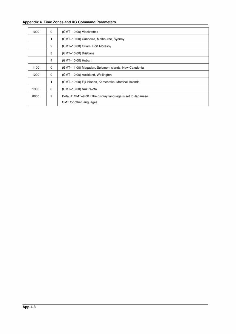
App-4.3
1000 0 (GMT+10:00) Vladivostok
1 (GMT+10:00) Canberra, Melbourne, Sydney
2 (GMT+10:00) Guam, Port Moresby
3 (GMT+10:00) Brisbane
4 (GMT+10:00) Hobart
1100 0 (GMT+11:00) Magadan, Solomon Islands, New Caledonia
1200 0 (GMT+12:00) Auckland, Wellington
1 (GMT+12:00) Fiji Islands, Kamchatka, Marshall Islands
1300 0 (GMT+13:00) Nuku'alofa
0900 2 Default: GMT+9:00 if the display language is set to Japanese.
GMT for other languages.
Appendix 4 Time Zones and XG Command Parameters
Index-1
1
2
3
4
5
6
7
App
Index
Appendix
Index
Aaccess control.................................................................... 2-19access privilege, granting of ................................................ 1-5administrator .............................................................. 1-5, 2-13affirmative response ............................................................ 5-3AK command ..................................................................... 5-31alarm line, setting of .......................................................... 5-28alarm, setting of ................................................................. 5-27alarm settings .................................................................... 5-33alarm status, acknowledgement of .................................... 5-31alarm summary .................................................................. 5-12ASCII character codes.....................................................App-1ASCII output response syntax ............................................. 5-4automatic file transfer .......................................................... 1-4automatic transfer ................................................................ 2-8average, setting of ............................................................. 5-29
Bbackground color, waveform line width, and alarm lin ....... 5-29bar graph base position, setting of .................................... 5-29basic setting command, setting whether to save or di ....... 5-36basic setting commands . 5-33, 5-34, 5-35, 5-36, 5-37, 5-38, 5-39, 5-40, 5-41, 5-42, 5-43basic syntax ....................................................................... 5-14baud rate ..................................................................... 3-3, 3-6BD command ..................................................................... 5-30binary output syntax .......................................................... 5-14block (measured/calculated/FIFO data output) ................. 5-17block member .................................................................... 5-17BO command..................................................................... 5-43BO flag............................................................................... 5-15burnout setting (query only) ............................................... 5-33BY command ..................................................................... 5-30byte output order, setting of ............................................... 5-43bytes, number of ................................................................ 5-16BZ command ..................................................................... 5-32
Ccalculating equation, setting of .......................................... 5-26calculation channels .......................................................... 5-24CC command..................................................................... 5-43channel display color and waveform line width, setti ......... 5-29checksum, setting of .......................................................... 5-43close command ................................................................. 5-48CM command .................................................................... 5-32command name ................................................................... 5-1command-response ............................................................. 5-3commands ........................................................................... 4-4communication channels ................................................... 5-24communication command log .............................................. 5-7communication distance ...................................................... 3-5communication error messages .................................. 7-8, 7-9communication function ....................................................... 1-1communication input data.................................................... 4-2communication input data, setting of ................................. 5-32communication interface, selection of ................................. 2-3communication interval ........................................................ 4-4communication log display ................................................ 2-16communication method, selection of ................................. 5-34communication timeout................................................ 1-5, 2-5con command .................................................................... 5-48
connection information, outputting of................................. 5-48connection status, checking ................................................ 2-7connection with other devices, disconnection of ............... 5-48CR+LF ................................................................................. 5-2CS command ..................................................................... 5-43CS-RS ................................................................................. 3-2
Ddata length ................................................................... 3-3, 3-6data length (binary output)................................................. 5-14data output flow ...................................................App-4, App-5data reception control .......................................................... 3-2data sum ............................................................................ 5-14data transmission control..................................................... 3-2date and time setting ......................................................... 5-27DC voltage ......................................................................... 5-23decimal place/unit information ............................................. 5-5Default Gateway .................................................................. 2-4delay sampling count, setting of ........................................ 5-30delimiter ............................................................................... 5-2device, closing of ............................................................... 5-47device, opening of ............................................................. 5-47DHCP .................................................................................. 2-3display backlight auto off, setting of ................................... 5-29display, switching of ........................................................... 5-31DNS ..................................................................................... 2-4DNS server .......................................................................... 2-4DNS Setting ......................................................................... 2-6DNS, setting of .................................................................. 5-37domain name ....................................................................... 2-4domain suffix ....................................................................... 2-4
Ee-mail and Web server errors .............................................. 7-4e-mail log ........................................................................... 5-11e-mail log display ............................................................... 2-18e-mail message, contents of.............................................. 2-31e-mail, setting the contents to be transmitted .................... 5-40e-mail SMTP server name, setting of ................................ 5-42e-mail transmission............ 1-6, 2-24, 2-25, 2-26, 2-27, 2-28e-mail transmission recipient address, setting of............... 5-41e-mail transmission sender address, setting of ................. 5-41e-mail transmission test ..................................................... 2-29EM command .................................................................... 5-32END flag ............................................................................ 5-15end trigger, selection of ..................................................... 5-35error log display ................................................................. 2-16error message log................................................................ 5-8ESC C command ............................................................... 5-47ESC O command............................................................... 5-47eth command ..................................................................... 5-48ETHERNET ......................................................................... 2-6Ethernet communication timeout, setting of ...................... 5-38Ethernet connection, disconnection of............................... 5-43Ethernet interface, checking the connection status of ......... 2-7Ethernet interface, configuration of.............. 2-3, 2-4, 2-5, 2-6Ethernet interface, connection of ......................................... 2-2Ethernet interface, specifications of..................................... 2-1Ethernet parameters, setting of ........................................... 2-3Ethernet statistical information, outputting of..................... 5-48EV command ..................................................................... 5-31execution errors ................................................................... 7-2
Index-2
Index
explanation of functions ....................................................... 1-3external storage media operation errors.............................. 7-3external storage medium, saving to................................... 5-31
FFC command ..................................................................... 5-45FD command ..................................................................... 5-45FE command ..................................................................... 5-45file list................................................................................. 5-13files, transferred ................................................................... 2-8filter ...................................................................................... 6-1FL command ...................................................................... 5-46flag (output byte order/checksum/END check) .................. 5-15FTP ...................................................................................... 1-1FTP client errors .................................................................. 7-5FTP client, setting of .................................................... 2-8, 2-9FTP destination ................................................................... 2-8FTP log display .................................................................. 2-17FTP server ........................................................................... 1-4FTP server name ................................................................. 2-8FTP test ........................................................... 1-4, 2-11, 2-12FTP transfer timing, setting of ........................................... 5-39FU command ..................................................................... 5-46function codes of the Modbus protocol ................................ 4-1
Ggroup, setting of ................................................................. 5-28
Hhandshaking ........................................................................ 3-3handshaking method ........................................................... 3-2header sum........................................................................ 5-14help command ................................................................... 5-48help, outputting of .............................................................. 5-48hold register ......................................................................... 4-2host name ............................................................................ 2-4HTTP ................................................................................... 1-1
IIA command....................................................................... 5-44IB command ...................................................................... 5-44ID command ...................................................................... 5-44identifier (binary data) ........................................................ 5-15IF command....................................................................... 5-43initial path ............................................................................ 2-9input range parameters ........................................... 5-23, 5-24input range, setting of ........................................................ 5-25input register ........................................................................ 4-2integrated value, calculation of .......................................... 5-16interval ............................................................................... 2-25IP ......................................................................................... 1-1IP address ........................................................................... 2-4IP Address Setting ............................................................... 2-6IP address, subnet mask, and default gateway ................. 5-37IS command ...................................................................... 5-46IT command ....................................................................... 5-44IU command ...................................................................... 5-42
KKE command ..................................................................... 5-32keep alive ............................................................................ 2-5keepalive ............................................................................. 1-6keepalive, setting of ........................................................... 5-37key login and auto logout functions, setting of................... 5-36key login log......................................................................... 5-9
LLAN port LED ...................................................................... 2-7language, setting of ........................................................... 5-34LF ........................................................................................ 5-2LI command ....................................................................... 5-31LO command ..................................................................... 5-31log and alarm summary, outputting of ............................... 5-46logging, starting/stopping of............................................... 5-31logic ................................................................................... 5-23login ............................................................................. 1-5, 2-5login name ........................................................................... 2-8login process .......................................................App-2, App-3
Mmaintenance/test commands....................................................5-22, 5-48, 5-49, 5-50, 5-51, 5-52maintenance/test communication command errors ............. 7-8maintenance/test server ...................................................... 1-3manual sampled data ........................................................ 5-18master (of Modbus) ............................................................. 4-1maximum number of simultaneous connections ................. 2-1ME command .................................................................... 5-46measured/calculated binary data syntax ........................... 5-16measured/calculated data ................................................... 5-6memory access error using setting/basic setting/outp......... 7-8Modbus error response ....................................................... 4-3Modbus Master .................................................................... 1-3Modbus master, data dropout handling of ................... 4-7, 4-8ModBus master error log ..................................................... 7-9Modbus master function ...................................................... 4-4Modbus master function, setting the command of ............. 5-40Modbus master function, setting the operation of.............. 5-40Modbus protocol .......................................................... 1-1, 4-1Modbus Slave ...................................................................... 1-3Modbus slave ...................................................................... 1-3monitor............................................................................... 2-19monitor page...................................................................... 2-19monitor page, contents of .................................................. 2-22monitor page, refreshing of................................................ 2-22most recent measured/calculated data, outputting o ......... 5-45multiple negative responses ................................................ 5-3
Nnegative response ............................................................... 5-3net command ..................................................................... 5-48network statistical information, outputting of...................... 5-48number of simultaneous users ............................................ 2-1
Index-3
1
2
3
4
5
6
7
App
Index
Appendix
Index
OOFF-OFF ............................................................................. 3-2operation, error messages related to... 7-3, 7-4, 7-5, 7-6, 7-7operator ............................................................................. 2-19operator page .................................................................... 2-19operator page, contents of................................................. 2-23other communication messages .......................................... 7-8output commands .............................................................. 5-22output commands (control) ...................................... 5-43, 5-44Output commands (RS-485 and USB dedicated commands) ..5-47output commands (setting/measurement/data output) .............5-45, 5-46output flow of the file list of the external storage .............App-4
Pparameters .......................................................................... 5-1parity check ................................................................. 3-3, 3-6password ............................................... 2-8, 2-13, 2-19, 2-20PASV mode ......................................................................... 2-8port number ............................................................... 2-8, 2-24primary ......................................................................... 2-4, 2-8privilege ............................................................................... 1-5PS command ..................................................................... 5-31pulse .................................................................................. 5-24
Qquery.................................................................................... 5-2query response .................................................................... 5-4quit command .................................................................... 5-52
Rrecipient ............................................................................. 2-24register assignments ........................................................... 4-2response syntax ............................................ 3, 5-4, 5-5, 5-6, 5-7, 5-8, 5-9, 5-10, 5-11, 5-12, 5-13, 5-14, 5-15, 5-16, 5-17, 5-18retrials .................................................................................. 4-4review display errors............................................................ 7-3RJC setting (query only) .................................................... 5-33RS-232 interface, setting of ................................................. 3-3RS-485 and USB communication dedicated syntax .......... 5-18RS-485 interface, setting of ................................................. 3-6RTD ................................................................................... 5-23
SSA command ..................................................................... 5-27sampling interval, setting of ..................................... 5-28, 5-33SB command ..................................................................... 5-29SC command ..................................................................... 5-29screen image data ............................................................. 5-18screen image data, outputting of ....................................... 5-45SD command ..................................................................... 5-27SE command ..................................................................... 5-29secondary .................................................................... 2-4, 2-8sender................................................................................ 2-24serial interface, setting of................................................... 5-38serial interface specifications............................... 3-1, 3-5, 3-7setting commands ................................................... 5-19, 5-21setting commands (control) ..................................... 5-31, 5-32setting commands (setting) ......................................................5-25, 5-26, 5-27, 5-28, 5-29, 5-30setting data, loading of ...................................................... 5-39
setting data, outputting of .................................................. 5-45setting data, saving of.............................................. 5-31, 5-39setting errors........................................................................ 7-1setting/basic setting/output communication and setti .......... 7-8setting/measurement server ................................................ 1-3setup data, loading of ........................................................ 5-31single negative response ..................................................... 5-3SL command ..................................................................... 5-28slave (of Modbus) ................................................................ 4-1slave address .............................................................. 3-3, 3-6SM command .................................................................... 5-26SMTP ................................................................................... 1-1SMTP server ...................................................................... 2-24SNTP ........................................................................... 1-6, 2-5SNTP (time synchronization function), setting of ............... 5-38SNTP Setting ....................................................................... 2-6SO command..................................................................... 5-26source URL ........................................................................ 2-25special data values ............................................................ 5-17SQ command..................................................................... 5-29SR command ..................................................................... 5-25ST command ..................................................................... 5-28standard protocol ................................................................. 1-1start trigger, selection of .................................................... 5-35start/stop (e-mail)............................................................... 2-31statistical calculation, setting of ......................................... 5-37status filter, setting of ......................................................... 5-43status information ...................................................... 5-12, 6-1status information, bit structure of ............................... 6-2, 6-3status information, outputting of ........................................ 5-46stop bit ................................................................................. 3-3sub delimiter ........................................................................ 5-2subnet mask ........................................................................ 2-4SV command ..................................................................... 5-29SW command .................................................................... 5-28SX command ..................................................................... 5-28system data output (query only) ........................................ 5-44
Ttag, setting of ..................................................................... 5-28TC ...................................................................................... 5-23TCP ..................................................................................... 1-1terminator .................................................................... 3-5, 5-2thermocouple ..................................................................... 5-23time zone, setting of .................................................. 2-3, 5-36timeout ................................................................................. 2-5timeout value ....................................................................... 4-4trigger, selection of ............................................................ 5-35
UUD command..................................................................... 5-31URL ................................................................................... 2-22USB ID, setting of ................................................................ 3-8user............................................................................ 1-5, 2-13user authentication .............................................................. 1-5user level ................................................................. 2-13, 5-14user level, outputting of ..................................................... 5-46user name...................................................... 2-13, 2-19, 2-20
VVOLT ................................................................................. 5-23
W
Index-4
Index
Web browsers .................................................................... 2-22Web operation log ............................................................... 5-9Web operation log display ................................................. 2-17Web server ............................................ 1-5, 2-19, 2-20, 2-21Web server function, enabling/disabling of ........................ 5-39
XXA command ..................................................................... 5-33XB command ..................................................................... 5-33XD command ..................................................................... 5-34XE command ..................................................................... 5-36XG command..................................................................... 5-36XH command ..................................................................... 5-36XI command ...................................................................... 5-33XJ command...................................................................... 5-33XK command ..................................................................... 5-35XL command ..................................................................... 5-35XO command..................................................................... 5-34XON-XOFF .......................................................................... 3-2XU command ..................................................................... 5-34XV command ..................................................................... 5-33XW command .................................................................... 5-37XY command ..................................................................... 5-37XZ commmand .................................................................. 5-35
YYA command ..................................................................... 5-37YC command ..................................................................... 5-39YD command ..................................................................... 5-37YE command ..................................................................... 5-38YG command..................................................................... 5-39YI command ...................................................................... 5-39YK command ..................................................................... 5-37YL command ..................................................................... 5-40YM command .................................................................... 5-40YN command ..................................................................... 5-37YO command..................................................................... 5-39YQ command..................................................................... 5-38YS command ..................................................................... 5-38YT command ..................................................................... 5-39YU command ..................................................................... 5-40YV command ..................................................................... 5-41YW command .................................................................... 5-41YX command ..................................................................... 5-42YZ command ..................................................................... 5-42

WARRANTY/DISCLAIMEROMEGA ENGINEERING, INC. warrants this unit to be free of defects in materials and workmanship for aperiod of 13 months from date of purchase. OMEGA’s WARRANTY adds an additional one (1) monthgrace period to the normal one (1) year product warranty to cover handling and shipping time. Thisensures that OMEGA’s customers receive maximum coverage on each product. If the unit malfunctions, it must be returned to the factory for evaluation. OMEGA’s Customer ServiceDepartment will issue an Authorized Return (AR) number immediately upon phone or written request.Upon examination by OMEGA, if the unit is found to be defective, it will be repaired or replaced at nocharge. OMEGA’s WARRANTY does not apply to defects resulting from any action of the purchaser,including but not limited to mishandling, improper interfacing, operation outside of design limits, improper repair, or unauthorized modification. This WARRANTY is VOID if the unit shows evidence of having been tampered with or shows evidence of having been damaged as a result of excessive corrosion;or current, heat, moisture or vibration; improper specification; misapplication; misuse or other operatingconditions outside of OMEGA’s control. Components in which wear is not warranted, include but are not limited to contact points, fuses, and triacs.OMEGA is pleased to offer suggestions on the use of its various products. However, OMEGA neither assumes responsibility for any omissions or errors nor assumes liability for anydamages that result from the use of its products in accordance with information provided byOMEGA, either verbal or written. OMEGA warrants only that the parts manufactured by thecompany will be as specified and free of defects. OMEGA MAKES NO OTHER WARRANTIES OR REPRESENTATIONS OF ANY KIND WHATSOEVER, EXPRESSED OR IMPLIED, EXCEPT THAT OFTITLE, AND ALL IMPLIED WARRANTIES INCLUDING ANY WARRANTY OF MERCHANTABILITYAND FITNESS FOR A PARTICULAR PURPOSE ARE HEREBY DISCLAIMED. LIMITATION OF LIABILITY: The remedies of purchaser set forth herein are exclusive, and the total liability of OMEGA with respect to this order, whether based on contract, warranty, negligence, indemnification, strict liability or otherwise, shall not exceed the purchase price of the component upon which liability is based. In no event shall OMEGA be liable for consequential, incidental or special damages.CONDITIONS: Equipment sold by OMEGA is not intended to be used, nor shall it be used: (1) as a “BasicComponent” under 10 CFR 21 (NRC), used in or with any nuclear installation or activity; or (2) in medicalapplications or used on humans. Should any Product(s) be used in or with any nuclear installation oractivity, medical application, used on humans, or misused in any way, OMEGA assumes no responsibilityas set forth in our basic WARRANTY/DISCLAIMER language, and, additionally, purchaser will indemnifyOMEGA and hold OMEGA harmless from any liability or damage whatsoever arising out of the use of theProduct(s) in such a manner.
RETURN REQUESTS/INQUIRIESDirect all warranty and repair requests/inquiries to the OMEGA Customer Service Department. BEFORERETURNING ANY PRODUCT(S) TO OMEGA, PURCHASER MUST OBTAIN AN AUTHORIZED RETURN(AR) NUMBER FROM OMEGA’S CUSTOMER SERVICE DEPARTMENT (IN ORDER TO AVOIDPROCESSING DELAYS). The assigned AR number should then be marked on the outside of the returnpackage and on any correspondence.The purchaser is responsible for shipping charges, freight, insurance and proper packaging to preventbreakage in transit.
FOR WARRANTY RETURNS, please have the following information available BEFORE contacting OMEGA:1. Purchase Order number under which the product
was PURCHASED,2. Model and serial number of the product under
warranty, and3. Repair instructions and/or specific problems
relative to the product.
FOR NON-WARRANTY REPAIRS, consult OMEGAfor current repair charges. Have the followinginformation available BEFORE contacting OMEGA:1. Purchase Order number to cover the COST
of the repair,2. Model and serial number of the product, and3. Repair instructions and/or specific problems
relative to the product.
OMEGA’s policy is to make running changes, not model changes, whenever an improvement is possible. This affordsour customers the latest in technology and engineering.OMEGA is a registered trademark of OMEGA ENGINEERING, INC.© Copyright 2005 OMEGA ENGINEERING, INC. All rights reserved. This document may not be copied, photocopied,reproduced, translated, or reduced to any electronic medium or machine-readable form, in whole or in part, without theprior written consent of OMEGA ENGINEERING, INC.

M4231/0805
Where Do I Find Everything I Need for Process Measurement and Control?
OMEGA…Of Course!Shop online at omega.com
TEMPERATURE Thermocouple, RTD & Thermistor Probes, Connectors, Panels & Assemblies Wire: Thermocouple, RTD & Thermistor Calibrators & Ice Point References Recorders, Controllers & Process Monitors Infrared Pyrometers
PRESSURE, STRAIN AND FORCE Transducers & Strain Gages Load Cells & Pressure Gages Displacement Transducers Instrumentation & Accessories
FLOW/LEVEL Rotameters, Gas Mass Flowmeters & Flow Computers Air Velocity Indicators Turbine/Paddlewheel Systems Totalizers & Batch Controllers
pH/CONDUCTIVITY pH Electrodes, Testers & Accessories Benchtop/Laboratory Meters Controllers, Calibrators, Simulators & Pumps Industrial pH & Conductivity Equipment
DATA ACQUISITION Data Acquisition & Engineering Software Communications-Based Acquisition Systems Plug-in Cards for Apple, IBM & Compatibles Datalogging Systems Recorders, Printers & Plotters
HEATERS Heating Cable Cartridge & Strip Heaters Immersion & Band Heaters Flexible Heaters Laboratory Heaters
ENVIRONMENTALMONITORING AND CONTROL Metering & Control Instrumentation Refractometers Pumps & Tubing Air, Soil & Water Monitors Industrial Water & Wastewater Treatment pH, Conductivity & Dissolved Oxygen Instruments
M-4710/1008