Embed Size (px)
Citation preview
RDTE PROJECT NO
USATECOM PROJECT NO 8-MU-013-069-003
USAIB PROJECT NO 3297
( USACDC AC NO
Y'%
SERVICE TEST OF
GRENADE, HAND, PRACTICE, XM69.%
FINAL REPORT
By
MAJOR DONALD J. MANON
December 1969
UNITED STATES A!r!Y INFANTRY BOARD-. Fort Benning, Georgia 31905
Thla &Cuaie b en apprarad
1 tib0d= 0 2nlt4
:":":8 5 1 0 0 2 12 4
.,*DEPARTMENT OF 11HE' ARMYHEADQUARTERS, U.,S. ARMY ThST ANL) EVALUA'rION COMMAND
AWrHOEEN PROVING Gr(OUND, MARYLAND 21005 I~CD.s~fr30
* SUBJE~CT: Final Report, Enginactring Tost miad Service Test of Grenado,Handc: Practice, D31!.y, X1169, USIC1TC, . Pro- -t Nos.* 8~--013-069-002 and 003
Projoct IManagor
ATTN: JCUSADover, IVeu J)-sey 073801
1. Refc~vroos.
a. Uetter, AUCI1-$A2, Projet 11nc fox, Selected kwiurition (FV-SA).dated 25 August 1969, subjoct: Granado, H&nd, Training, D:-lay, YJ69,.
b. lotter, F011-014.T, Lk--part-c~nt of tbo Arm~y, drutod 8 Octobor 1969,subject: Delotion of Coumpo.,ioit ltcm.:; to 1Iland GronAde, Practice.
c. Ji4ttcr, AMSTE..IM, US Iu-ty Tost irid Einlution. Commandl (u's1TFCao:),da'tec 26 Fovcnb:!r 1969, subject: Scirvicc Tost Plana for Gronadc, Hand,Practice, X1169 with 1st 1ndorsc4r.on-t, ATOPS.-TEG-TS!4, US Continontal AryCoe:mand (C0O1ARC), dated 16 Deceumber 196',
d. 114ussago, fi!iF:'1'R-13C, USATE'1E0, dzatcl 17 Fe-bruary 1970, subject asabove.
2. hatoxal Statemor.t. Subject reports aro approved.
3. B 0kground ofTort.
a. Departm3nt of tlto Ar~my directc-d the ropJlocentinnt of the 126-serics1E,,,nd Grerade with the Irqprovod 1I33-.soreos I.ud Gr'-nach'- (Dasc'ball). Is a
S result, It was neecssor'y to provido i p-activa rrrja-.oe:.for the now staneardgrenade. In orec;, to ais.ma-c propor ) troop trlOulin n tho Use Of thor v.c rnt).y ch'.rmgc' body rharp of' tho e t 2.derd ite~r,, subject practice gr-iaadawas xopd
SUBJ C: Final Report, Engineering Test and Service Test of Grenade,Bond: Practice, Delay, X11(90 USATIRC0I Projoct Los. 84-11.013-069..002 and 003
b. With the introduction of secondary safety clip for bhnd grenades,tho model designators were chanjed froai those associated with the'saegrenades with a safety pin onlya Listed are the zodol numbers'of pertinont
, H and practice grenades and equivalont ones with the safety clip added:
GPMNAYDT' 1ODL
... . W-th Safety C3,4JEc Urotice. IN- prilcticeYN6(val P13
Shaped)
M33(Rasoball None 1467 X169 (Test Item)Shapad
o, The xM69 practice band grenado consists of five basic parts8a reusable non-fragmonting body,"a black powdor charge, the X1228 fusesa plastic stopper, and a secondary safety clip.
d. The engineering test was conducted at Aberdeen Proving Ground (APG)and te service test at t- US Army Infantry Board (USAIB). No additlona]testing of subject item is currently prograwmod.
4. Test Results.
a. No deficiencies or shortcomings were found during testing.
b. The test item met all of the 17 require:ents. A total of 705 testgrenades and 45 control grenades (162) wore detonated during serviceo testingand 375 test grenedo were detonated during engineoring tooting.
o. The overall functioning reliAbility was 94o at the 90% confidencelciel for the engineering test and 98. at the 90,, confidence level forthe service test. The established criterion was 93% reliability at the90% confidence level and this was met in each test.
d. The test grenade was capable of being reused as many times as theM62 control gronade.
e. The test grenade was sufficiently durable to wfthstand the abusenornally encountered in training.
f. The test grenade required no maintenance in excess of that' requirodfor the 1162 control grenade.
g The average fuid functioning tbie for the practice test grenadewas comparable to that of its standard counterpart.
. Coment s.
a.. No specjfic ]iiitery charactristics have been stated for the test
)1,STE-BC "'"
ps
S- -ET S, or. d
SUP.JECT: Final Report, Engineering Test and Service Test of Orenr.3e,Hand: Practice, Delay, X,169, USATECOH4 Project gose 8,1113..013-069-002 and 003
5Item. Howovor, the test grenade was dessigned to moot the specIficationand safoty requirements established for other plactico grenades, considerbthat it utilized formor Standard A cOuponcnts with minor alterations.Criteria selected ware the same as those used for the previous standard, .praotice grenade, 1462. '
b. The test item compared favorat3., with the controi practico grnadein all aspects. Ton trainees from tl:e US Army Training Center, Fort "9 kBonning, Georgia, Judgeod the test grenade to be easier to handle andthrow than the control grenaele. There ,as no significant difference inscores obtained using both grenados whilo running the grenade assaultcourse.
o. The powder charge and plastic plug wore considered to bo nonossentlitems since tost soldiers could dotoot. the point of detonation 40 motorsaway by the noise and smoke coused by detonation of the futod body withouttb3 powder charge and plug.
d. By massago referenced in paragraph Id, this headquarters respondodto an urgent request from Picatinny Arsein'l for a formal position as tothe suitability for Army use of the tested item. The oonolusions beloware reite:ations.
6. £~~3B
a, The M169 Practice Hand GrenAeo is suitable for US ArvW use.
b. The powdor charge and plastic plug are nonessential componentsof the X169 Practice Hand Gronad3.
7. Recomnondetion. The powder charge aid plastic plug b3 deleted ascompoi ontotl"" 1469 Practice Hand Grenade.
FOR THE CO4M.AMDER:
GOOD3,'J flORROWActing Directorinf Nat Test Dir
Copies furnishoc1:CG USMIC ATTN: AXcRD.J,; (2 cys ea)
A,4CiRD-U (I cy 0a)AMCiR-CP (2 cys ea)
0G CONARC ATTN: ATIT..RD-4, (4 cys on)CO PA ATTN: SYU'fi-EX'15 0 eys ea)USLCDC LO, USATEM. (2 cys aa)
.-3
Distribution
Titis document may be further distributed by any holder only with thesp&..fic prior approval of Commanding General, US Army MunitionsComand, ATTN: AMCPH-SA, Picatinny Arsenal, Dover, New Jersey 07801.
Disposition Instructions
Destroy this report when it is no longer needed. Do not return itto the originator.
-S
RDTE PROJECT NO
IUSATECOM PROJECT NO 8-MU-013-069-003
USAIB PROJECT NO 3297
USACDC AC NOka
SERVICE TEST OF
GRENADE, HAND, PRACTICE, V469
FINAL REPORT
By
MAJOR DONALD J. MAW-ON
December 1969
UNITED STATES AP11Y INFANTRY BOARDFort Benning, Georgia 31905
NNW 1WWR on W uwu7~'w~w- T MWRW WW &19MITWM
ABSTRACT
A Service Test of the XK69 Practice Hand Grenade (XM69) (with XA228fuze) waw conducted by the US Army Infantry Board (USAIB) at Fort Benning,
Georgia, from 3 November to 8 November 1969. The purpose of the test was todetermine, under actual or simulated field ccnditions, the suitabilityof the XM69 and its associated reusable spare parts for use as a trainingitem by the US Army.
Specific test phases to which the XM69 was subjected were physicalcharacteristics, safety, functional suitability, reliability, durability,maintainability, human factors, and value analysis. The performance ofthe XK69 was compared to the M67 fragmentation hand grenade and the 462practice hand grenade in applicable subtests.
There were no deficiencies or shortcomings found during testing.It was found during the Value Analysis subtest that the powder charge
and plastic plug were nonessential items. The test grenade, if cleanedof all foreign matter after each throw, can be reused a minimum of 300times.
An interim report of test was submitted to Headquarters, US ArmyTest and Evaluation Coemand on 12 November 1969 giving tentative resultsand recomendations. This final report reflects the same results andrecommendations.
USAIB concluded that the X469 Practice Hand Grenade is suitablefor US Army use, and recommended that the powder charge and plastic plugbe deleted as components to the XM69.
FOREWORD
The US Army Infantry Board was responsible for test planning, testexecution, and test reporting.
'.
4
r
.u ,,i•
TABLE OF CONTENTS
PAGE
ABSTRACT9 ... . . . . . . . . . . . . . . . . . 9 . . . . . . . i
FORE ORD. . . . . . . . . . . . . . . . .o o o 9 a o 9
SECTION 1. Sthf4ARY
1.1 BACGROUND .............. 1-11.2 DESCRIPTION o MTEIN LA T..... E... . ...... 1-21.3 TEST OBJECTIVES . . . . . . . . . . . . . . . . . o a .* * s 1-2194 SCOPEs . . .o . . . . .o v. . . . . . . . . . . . .0 a * 0 0 0 1-31.5 SUMMARY OF RESULTS . . . . . . . . . . . . . o . . . . . . . 1-31.6 CONCLUSIONS. . . . . . . . . . . . . . . . . . . . . . . . 1-41.7 RECOMMENDATIONS. . . . . . . . . . . . . . . . . . o .s 1-4
SECTION 2. DETAILS OF TEST
2.1 SUBTEST NO 1, PREOPERATIONAL INSPECTION AND PHYSICALCHARACTERISTICS . . . . . . . . . . . . . . . . . . . . . 2-1
2.2 SUBTEST NO 2, SAFETY . . . . . . . . . - .... . . a 2-22.3 SUBTEST NO 3, FUNCTIONAL SUITABILITY, RELIABILITY, AND
DURABILITY .. . . . . . . . . . . . . . . . . . . . . . . 2-42.4 SUBTEST NO 4, MAINTAINABILI TY ...... ......... . 2-92.5 SUBTEST NO 5, HUMAN FACTORS. . ....... ...... .. 2-102.6 SUBTEST NO 6, VALUE ANALYSIS . ...... . ........ 2-12
SECTION 3. APPENDICES
I TEST DATA* o. . . . .. . . . ... o o. . . . . . . .o s st I-1
II TESTFIENCIES .NDS.ORTCOMING. . . . . . . . . . . . . . . . I1-I
IV MAINTENANCE EVALUATION . . .. ............... iV-IV REFERENCES .. . . . . . . . . . . . . . . . . . . . a . . V-1VI ABBREVIATIONS . . . o . . . . . . . . . . . . . . . . .. Vt-1VII DISTRIBUTION LIST .... ......... .. . VII-I
ti
SECTION 1. SUMMARY,
1.1 BACKGROUND
1.1.1 With the introduction of the secondary safety clip in the design
of the current family of hand grenades, the model numbers of thegrenades with safety clip were changed from the numbers associatedwith those grenades with safety pin only. Listed below are the originalmodel numbers of pertinent current standard grenades and the corresponding
ones with safety clip.
ORIGINAL WITH SAFETY CLIP
M26A1 HE w/M204A2 Delay Fuze M61
M30 Practice w/M.205A2 Practice, Delay Fuze 462
M33 HE v/M213 Delay Fuze M67
1.1.2 The M67 HE, Fragmentation Hand Grenade is being fielded and it
is understood that it may eventually replace the M61-type hand grenades
in Army use. There is at present no practice version of this handgrenade. Therefore, with the fielding of the HE version of the M67
grenade, a requirement for a practice version exists. Picatinny Arsenal
was given the task of developing a companion practice hand grenade.This has led to the development, on an expedited basis, of the X469Practice 9and Grenade (XM69) with XK228 Practice Hand Grenade Fuze(Delay) (X4228). I
1.1.3 No specific military characteristics have been stated. The testgrenade was designed to meet the specification and safety requirements
established for other practice grenades. An engineer design test ofthe XK69 was scheduled by Y-!eriel Test Directorate at Aberdeen ProvingGround, Maryland, for the second quarter of fiscal year 1970.
1.1.4 On 3 October 1969 the US Army Test and Evaluation Comnand (USATECOM)
directed the US Army Infantry Board (USAIB) to conduct a service test of
,he XM69 under prevailing intermediate climatic conditicas at Fort
Benning, Georgia.
1.1.5 Testing was conducted during the period 3 November - 8 November 1969.
1.1.6 An interim report of service test was submitted to Headquarters,USATECOM on 12 November 1969 (ref 15, app V).
1-1
1.2 DESCRIPTION OF MATERIEL (See figure 1, app I, showing components)
- 1.2.1 The hand g'.enade, XM69, consists of 5 basic parts:
a. A reusable non-fragmenting body.
b. A black powder charge.
c. An XH228 fuse.
d. A plastic stopper.
e. A, safety clip.
1.2.2 The XM69 grenade body is Pade of steel and is painted blue witha -inch-wide brown band around the neck of the body. The maximum
diameter is 2.62 inches and the complete weight, loaded and fused, is
14 ounces.
1.2.3 The charge is 37.5 grains of black powder contained in a plasticbag. This charge is the same as used in the M62 practice grenade.
1.2.4 The fuse, X4228, is identical to the M213 delay (4 to 5 secondo;fuze used in the M67 grenade except 10 grains of bl.-ek powder replace
the high explosive booster pellet in the booster cup. The XM28 usesthe same components as the 213 fuze and its functional and physicalcharacteristics are identical to the M213 fuse in all other respects.
1.2.5 The plastic plug is the same as the plastic plug used in theM62 practice grenade.
1.2.6 The safety clip is a device to keep the grenade handle in place
ahculd the safety pin be unintentionally withdrawn and is used inconjunction with the safety pin. It is the same safety clip that isused with the M67 grenade.
1.2.7 The XM69 grenade is not issued as a complete round; the components
are issued as required.
1.3 TEST OBJECTIVES
1.3.1 The overall service test objective was to determine, under actual* , or simulated field conditions, the suitability of the k169 practice
grenade, and its associated reusable spare parts, for use as a trainingitem by the Army.
1.3.2 To confirm that the XM69 practice grenade is safe for Army use.
1.3.3 To evaluate the maintenance package and maintenance procedures
in accordance with USATECOM Reg 750-15 and AMC Reg 750-15.
1-2
1.4 SCOPE
The service test was conducted at Fort Benning, Georgia, duringthe period 3 November - 8 November 1969. Six test soldiers from USAIB'And ten trainees from the US Army Training Center, Fort Benning, Georgia,representative of those who would be expected to use and maintain theXV69 during training, were used in testing. The M62 practice grenadeand the M67 fragmentation grenade were used as control grenades. Thecontrol grenade (M67) was used for comparison purposes with the XM69in the Physical Characteristics and Human Factors subtests. The controlgrenade (M62) was used for all other comparison purposes with the XM69.Testing was conducted under field training conditions. Temperaturesduring testing varied from 450 to 683 F. Seven hundred and five test
grenades and 455 control grenades (M62) were detonated during testing.The fuze functioning time was determined by detonating 678 test grenadesand 434 control grenades (M62) of the above total. Since a separate Quali-tative Materiel Requirement exists for a maneuver training grenade, tac-tical aspects of testing such as compatibility with load carrying equipmentwere not addressed.
On 28 October 1969, US Continental Army Command directed the US ArmyInfantry School (USAIS) to delete the use of powder charge and plasticplug as components to the M62 Practice Hand Grenade (ref 14, app V).Because of this directive, additional exercises were conducted whereinthe test grenades were thrown without pcwder charge and plastic plug.The purpose of these exercises was to determine whether the XM69 usedwithout powder charge and plastic plug gives the desired tral-ing results.
During the reusability exercise, one test grenade was reused 300times without the powder charge and plascic plug. During the exercise
in Subtest 3, when six test grenades ad six cointrol grenades (M62)were reused 50 times, three of the test grenade bidies and three of thecontrol grenade bodies (M62) were flt cleaned if a'l foreign ma6ter aftereach throw. The purpose of this was t-) obtain informatio'n ,n hcw manytimes the grenade bodies could be reused befire the bodies had t , becleaned prior 0o inserting a new fuze.
1.5 SUMMARY OF RESULTS
1.5.1 There were no deficiencies or sI,.rtc,,mings found during testing.
1.5.2 With the exception of color and markings and an irsigriffcar-weight difference, the test grenade has the same physical characteristicsas the control grenade (M67) (Subtest N,, 1).
1.5.3 The test grenade required no addi'_, nal safety precaut'ons thanrequired for the control grenade (M62) and was considered safe fr US
"* Army use (Subtest No 2).
1.5.4 The test grenade exceeded the desired func:inal reliabilitycriteria of 9o% (90% level of c,-.nfidence) (Suttesc No 3).
1-3
1.5.5 The average fuze functionin- time for the test grenade was between
4.0 seconds and 5.0 seconds (Subtest No 3).
1.5.6 Test soldiers could detect the point of detonation of the testgrenade (when used with or without the powder charge and plastic plug)40 meters away by the noise and smoke caused by its detonation.
1.5.7 The test grenade was capable of being reused as many times as thecontrol grenade (M62). "'The test grenade, if cleaned of all foreign matterafter each throw, can be reused a minimum of 300 times (Subtest No 3).
1.5.8 The test grenade was sufficiently durable to withstand the abusenormally encountered in training usages (Subtest No 3).
1.5.9 The test grenade required no maintenance in excess of that requiredfor the control grenade (M62) (Subtest No 4).
1.5.10 The test grenade was suitable with respect to the capabilities,limitations, and habit patterns of the soldier user (Subtest No 5).
.51.5.11 The powder charge and plastic plug were considered to be non-.essential item. No other nonessential or "nice-to-have" items werefound during testing (Subtast No 6).
1.6 CONCLUSIONS
a. The XR69 Practice Hand Grenade meets all criteria established.
b. The powder charge and plastic plug are nonessential componentsof the 469 Practice Hand Grenade.
c. The XM69 Practice Hand Grenade is safe for US Army use.
d. The XM69 Practice Hand Grenade is suitable for US Army use.
1.7 RECOKMENDATIONS (no change from interim report)
The United States Army Infantry Board recommends that the powdercharge and plastic plug be deleted as comnonents of the XH69 PracticeHand Grenade.
1-4
SECTION 2. DETAI-LS OF TEST
2.1 SUBTEST NO 1, PREOPERATIONAL INSPECTION AND PHYSICAL CHARACTERISTICS
2.1.1 ObJectives
2.1.1.1 To determine the receipt condition of the test grenade.4
2.1.1.2 To verify the completeness of the shipment.
2.1.1.3 To determine whether the test grenades were in condition to betested.
2.1.1.4 To compare the physical characteristics of the test grenade withthose stated in the Draft Technical Manual (MV ) and with those of theM67 fragmentation grenade.
2.1.2 Criteria
2.1.2.1 The size, weight, and shape of the test grenade must be thesame as the control grenade (M67). (Ref item 1, app II)
2.1.2.2 Except for color and markings which identify it as a trainingdevice, the identification features of the test grenade must be thesam as the control grenade (M67). (Ref item 2, app 11)
2.1.3 Method
2.1.3.1 The test grenade's components were inspected for serviceabilityand for any evidence of damage incurred during shipment.
2.1.3.2 The test grenade's components were counted and the total comparedagainst the total listed in the shipping document. The lot numbers ofthe test fuzes were compared against the lot numbers listed in theshipping documents. The Federal Stock Numbers (FSN) in the shippingdocument were compared with the FSN's listed in the DTH.
2.1.3.3 Three test grenades and three control grenades (M62) werethrown to determine whether the grenades were in condition for testing.
2.1.3.4 Three test grenades were weighed, measured, and photographed.
2.1.3.5 Three control grenades (M67) were weighed, measured, and
photographed.
2.1.4 Results
2.1.4.1 All test grenade components were found to be in serviceablecondition and no items were damaged in shipment.
2-1nIinr7
2.1.4.2 Eight hundred X4228 test fuzes (80 Lot No 90414 - 720 Lot No 90576),250 plastic base plugs, 250 safety clips (XM69), 500 M205A2 fuze (Lot No1OP-9-2), 250 safety clips (M62), 1200 powder charges, 50 steel bodies,XK69, 50 cast iron bodies, M62, 120 M67 fragmentation hand grenades, and60 M61 fragmentation hand grenades were present for testing. All test
*components' FSN's were the same as the FSN's listed in the DTM.
2.1.4.3 Three test grenades were thrown and functioned satisfactorily.Three control grenades (N62) were thrown and functioned satisfactorily.
2.1.4.4 The average weight and width measurements of 3 test grenadeswere 14.77 ounces, and 2.5 inches, respectively. Photographs of the testgrenade and components are shown in figure 1, app I.2.1.4.5 The average weight and width measurements of 3 control grenades
were 15.52 ounces, and 2.5 inches, respectively. A photograph of thecontrol grenade (M67) is shown in figure 2, app I.
2.1.4.6 The test grenade and control grenade have the same physicalcharacteristics with the exception of color and markings.
2.1.5 Analysis
2.1.5.1 All test items were in serviceable condition and in sufficientquantity for testing.
2.1.5.2 The required amount of test and control itevs was on hand toinitiate testing.
2.1.5.3 The test grenades and control grenades (M62) functionedsatisfactorily.
2.1.5.4 With the exception of color and markings and an insignificantaverage weight difference of .7 ounce less than the control grenade,the test grenade has the same physical characteristics as the controlgrenade (M67).
2.2 SUBTEST NO 2, SAFETY
2.2.1 Objectives
2.2.1.1 To determine the effectiveness of the safety features of thetest grenade.
2.2.1.2 To determine the adequacy and comileteness of the safetyinstructions contained in the DTM and the developer's safety release.
2-2
2.2.2 Criteria
The grenade must require no additional safety precautions beyondthose currently required for the standard practice grenade. (Refitem 3, app II)
2.2.3 Method
2.2.3.1 During all testing observations were made to determine theeffectiveness of the safety clip and safety pin in precluding accidentaldetonation. (A total of 705 test grenades and 455 control grenades (M62)was thrown with safety clip and safety pin a:tached.)
2.2.3.2 All prccautions or limitations prescribed in the DTH and thedevelopers safety release for the test grenade were observed during alltesting.
2.2.3.3 Ten test grenades and 10 control grenades (462) (all withsafety clip, fuze, powder bag, and plastic plug) were detonated one ata time in the center of a circle with a radius of 18 meters. The outeredge of the circle had a 6-foot-high wall constructed of brown wrappingpaper. A 3-fobt-high wall of brown wra~ping paper was also constructedwithin the above circle at the 3, 10-, and 15-meter marks. Observationswere made during this exercise to determine whether the primer holderand striker assembly of the fuze or any other parts of the grenade wereprojected as fragments beyond 18 meters.
2.2.3.4 The exercise described in paragraph 2.2.3.3 was repeated exceptno powder charge and plastic plug were used.
2.2.3.5 Observations were made during all subtests on the safety
aspects of the test grenade.
2.2.4 Results
2.2.4.1 No accidental detonations occurred during testing.
2.2.4.2 No additional nrecautions or limitations other than thoseprescribed in the DTM and the developer's safety release were observedduring testing.
2.2.4.3 During the exercise described in paragraph 2.2.3.3 no fragmentswere projected beyond 10 meters from the center of the circle.
2.2.4.4 During the exercise described in paragraph 2.2.3.4 no fragmentswere projected beyond 5 meters from the center of the circle.
2-3
2.2.5 Analysis
2.2.5.1 The safety clip and safety pin preclude accidental detonationof the test grenade.
2.2.5.2 The safety portion of the DTM and the developer's safety releaseis adequate.
2.2.5.3 The test grenade when functioned with the safety clip, fuze,powder charge, and plastic plug requires no additional safety precautionsthan required for the control grenade (M62).
2.2.5.4 The test grenade when functioned without powder charge andplastic plug requires no additional safety precautions than required forthe control grenade (M62) without powder charge and plastic plug.--,.
2.2.5.5 The test grenade is safe for US Army use when used as describedin the DTM.
2.3 SL'TEST NO 3, FUNCTIONAL SUITABILITY, RELIABILITY, AND DURABILITY
2.3.1 Objectives
2.3.1.1 To determine the functional suitability of the test grenade.
2.3.1.2 To determine the reliability of the test grenade.
2.3.1.3 To determine the durability of the test grenade.
2.3.2 Criteria
2.3.2.1 This practice item must function reliably in 95% of usage(essential) 98% (desirable). (Ref item 4, app IT)
2.3.2.2 The test grenade shall detonate by action of the time elementbetween 4.0 to 5.0 seconds after arming. (Ref item 5, app II)
2.3.2.3 The noise and smoke produced by the detonation of the testgrenade must be sufficlet to enable the average soldier to detectdetonation at 40 meters. (Ref item 6, app II)
2.3.2.4 This test grenade body will be capable of reuse as many timesas the control grenade (M62). (Ref item 7, app II)
2-4
41.
2.3.2.5 This test grenade will be sufficiently durable to withstandthe abuse normally encountered in training usage. (Ref item 8, app II)
2.3.3 Method
2.3.3.1 During the conduct of all testing a total of 455 controlgrenades (M62) and 705 test grenades was thrown.
2.3.3.2 Six test soldiers each threw a total of 55 control grenades(M62) (1 grenade body was reused 50 times and the remaining 5 were ran-domly selected grenade bodies) at a target located 40 meters to theirfront. The center of the target had a distinct aiming point. The fuzefunctioning time was recorded by 3 NCO recorders with stop watches.After each throw the test soldier inspected the body of the grenade forcracks and cuts and then reloaded the grenade with a fuze, powder bag,plastic plug, and safety clip. Three of the grenade bodies were cleaned
of all foreign matter prior to reloading, and three of the bodies werenot cleaned but reused until cleaning became necessary to fit the fuze,powder charge, and plastic plug into the grenade body. The test soldierswere questioned after each throw to determine whether they could detectthe point of detonation of the grenade by the noise and smoke.
2.3.3.3 Six test soldiers each threw a total of 55 test grenades (1grenade body was reused 50 times and the remaining 5 were randomlyselected grenade bodies) at a target located 40 meters to their front.The center of the target had a distinct aiming point. Three NCOrecorders measured the fuze functioning time with stop watches. Thisinformation was verified by use of a visicorder. After each throw thetest soldier inspected the body of the grenade for cracks and cuts andthen reloaded the grenade with a fuze, powder bag, plastic plug, andsafety clip. Three of the grenade bodies were cleaned of all foreignmatter prior to reloading; three of the bodies were not cleaned butwere reused until cleaning became necessary to fit the fuze, powder charge,,and plastic plug into the grenade body. The test soldiers were questionedafter each throw to determine whether they could detect the point ofdetonation of the grenade by the noise and smoke. The detonation of10 of the grenades thrown in this subtest was photographed with a highspeed camera and compared in the Value Analysis subtest.
2.3.3.4 Six test soldiers each threw 2 test grenades and 2 controlgrenades (M62) with powder charge and plastic plug into a ditch filledwith 6 inches of watec, located 5 meters to their front. (In the planof test it called for a distance of 25 meters, but this was changed to5 meters to insure that all grenades went into the water.) The fuze
' functioning time on all grenades was measured by 3 NCO's with stopwatches. After each throw the test soldier inspected the body of the
grenade for cracks and cuts. Observers were stationed 40 meters fromthe ditch and were questioned fter each throw to determine whetherthey could detect the point of detonation of the grenade by the noiseand smoke.
2-5
2.3.3.5 The exercise described in paragraph 2.3.3.4 was repeated exceptthat 5 test soldiers each threw only 2 test grenades without powdercharge and plastic plug.
2.3.3.6 Six test soldiers each threw 6 test grenades and 6 contiolgrenades (M62) (with powder charge and plastic plug) on a concreteslab located 25 meters to their front. (In the plan of test, eachtest soldier was to throw 2 each test and control grenades, but thiswas increased to 5 each to get a better sample size.) The fuzefunctioning time was measured on all grenades by 3 NCO's with stop-;watches. After each throw the test soldier inspected the body of thegrenade for cracks and cuts. '. .
2.3.3.7 One test grenade body without fuze, safety clip, powder chargeand plastic plug was thrown 8 times against a concrete wall with fullforce from a distance of 5 meters to inflict maximum punishment on thebody. After each throw the grenade body was inspected for cracks and cuts.
2.3.3.8 One control grenade body (M62) without fuze, safety clip, powdercharge, and plastic plug was thrown 2 times against a concrete wall withfull force from a distance of 5 meters to inflict maximum punishment onthe body. After each throw the grenade body was inspected for cracksand cuts.
2.3.3.9 Six test soldiers each threw 2 test grenades and 2 controlgrenades (M62) at a wooden wall located 25 meters to their front. Thefuze functioning time was measured on all grenades by 3 NCO's with stopwatches. After each throw the test soldier inspected the body of thegrenade for cracks and cuts. . *
2.3.3.10 One of the test grenade bodies reused fifty times inparagraph 2.3.3.3 was reused an additional 250 timdes, without powdercharge and plastic plug. The interior of the grenade body was cleanedof accumulated foreign matter only when it became necessary to do so topermit the insertion of a new fuze. The fuze functioning time on allgrenades was measured by 3 NCO's with stop watches.
2.3.4 Results
2.3.4.1 During all testing a total of 455 control grenades (M62) wasthrown. One fuze failed to function.
2.3.4.2 During all testing a total of 705 test grenades was thrown.Seven fuzes failed to function. The 7 failures were caused by thestriker of the fuze not impacting the primer with sufficient force tocause detonation. The app.rent reason for this lack of force was the lackof a proper angle on the top of the striker caused by incorrect stampingduring manufacture (see figure 3, anp I). Two of the 7 fuzes hAd thestrikers replaced with previously thrown strikers and were detonated.
2.3.4.3 Neither the test grenade nor control grenade (M62) bodies wereappreciably damaged by impact or detonation exceut the test and controlbodies mentioned in naragraphs 2.3.4.11 and 2.3.4.12.
2--6
2.3.4.4 The desired functional reliability of 98% with a 90% level ofconfidence was exceeded by both the test grenade and the controlgrenade (M62). The test grenade, using a sample size of 705 with 7failures, obtained a 98% reliability with a 96% level of confidence.The control grenade (M62), using a sample size of 455 with 1 failure,obtained a 98% reliability with a 99+% level of confidence.
2.3.4.5 During all testing a total of 434 control grenades (M62) hadthe functioning time of the fuze measured with stop watchei. Theaverage functioning time was 4.96 seconds. No times were recordedbelow 4.0 seconds and 5 were recorded above 5 seconds (see chart 3-1,app I).
2.3.4.6 During all testing a total of 678 test grenades had the 0functioning time of the fuze measured with stop watches. During theexercise described in paragraph 2.3.3.4, only 280 test grenades out ofthe 330 test grenades fired were recorded with the visicorder due totechnical difficulties with the visicorder. The average time ofthe functioning of the 280 test fuzes recorded with the visicorder was4.67 seconds. The average time of the functioning of the 678 testfuzes recorded by stop watches was 4.74 seconds. None of the timesrecorded with the visicorder or with the stop watches was below 4.0seconds or above 5 seconds (see chart 3-2, apo I).
2.3.4.7 During all testing the test soldiers were able to identify thepoint of detonation from 40 meters away by the noise and smoke producedby the detonation.
2.3.4.8 During the exercises described in paragraphs 2.3.3.2 and 2.3.3.3,6 test grenades and 6 coutrol grenades (M62) were reused 50 times each.No damage was incurred to either the test grenade or control grenade (462)body by the impact with the ground or the detonation. The test soldierswho threw the 3 test grenades and 3 control grenades (M62) which werecleaned of all foreign matter after each throw had no difficulty ininserting the new fuze, powder charge, and plastic plug into the grenadebody. The test soldiers who threw the 3 test grenades and 3 controlgrenades (N62) that were not cleaned of all foreign matter aftereach throw experienoed some difficulty in inserting the new fuze,powder charge, and plastic plug into the grenade body due to a build-upof aluminum residue from the expended fuze.
2.3.4.9 During the exercises described in paragraphs 2.3.3.4 and 2.3.3.5,
all grenades functioned. The point of detonation was detected by observersstationed 40 meters away by the noise and smoke caused by the detonation.The signature effects of noise and smoke produced by the test grenadeswhen thrown without powder charge and plastic olug were not as noticeableas when thrown with the powder charge and plug, but were clearly audibleand visible to the observers stationed 40 meters away. No damage wasincurred on any of the grenade bodies by the impact of the grenade orits detonation.
2-7
2.3.4.10 During the exercise descriltod in paragraph 2.3.3.6, all grenadesfunctioned and no apprecLable damaga occurred to the grenade bodies bythe impact or the detonation.
2.3.4.11 During the exercise described in paragraph 2.3.3.7, the testgrenade body was noticeably dented after eight throws (see figure 5,app I). A new fuze and plug were inserted into the grenade body andit functioned properly.
2.3.4.12 During the exercise described in paragraph 2.3.3.8, the controlgrenade body (M62) shattered upon impact with the concrete wall afterthe secoad throw (see figure 4, app I).
2.3.4.13 During the exercise described in paragraph 2.3.3.10, the testgrenade body was reused 250 times for a total of 300 times for thatparticular grenade body. The powder charge and plastic plug were notused in this exercise. The grenade body was not cleaned of all foreignmatter after each throw, but was reused until it was necessary toclean it to insert a new fuze. Chart 3-3, appendix I, depicts whencleaning was required to insert a new fuze and time required to cleanthe grenade body. The grenade body was inspected after each throw andthere was no damage to the grenade body. The test grenade reused 300times was cut open upon completion of the exercise and the inside ofthe g:enade was examined. No deterioration or damage was detected onthe inside of the grenade body.
2.3.5 Analysis
2.3.5.1 The test grenade and control grenade (462) exceed the desiredfunctional reliability criteria of 98% (90% confidence level).
2.3.5.2 The average fuzt. functioning time for the test grenade andcontro; grenade (M62) is bel:ween 4.0 seconds and 5.0 seconds, meetingthe established criteria.
2.3.5.3 The average soldier is able to detect the point of detonation ofthe test grenade and control grenade (M62) 40 meters away by the noiseand smoke caused by its detonation.
2.3.5.4 The t.est grenade body is capable of being reused as many timesas the control grenade (M62) and could be reused indefinitely if cleanedof all foreign material after each throw.
2.3.5.5 The test grtnade and control grenade (M62) are sufficientlydurable to withstand the abuse normally encountered in training usage.
2-8
_-S
2.4 SUBTEST NO 4, MAINTAINABILITY
2.4.1 Objective
To determine the adequacy of the maintenance portion of the DVfor the test item.
2.4.2 Criteria
The grenade shall require no maintenance in excess of that requiredfor the control grenade (M62). (Ref item 9, app II)
2.4.3 Method
2.4.3.1 During testing, all maintenance prescribed by the DTM wasperformed on the test grerade and control grenade (M62).
2.4.3.2 During testing, all maintenance performed on the test grenadeand control grenade (M62) was recorded and compared.
2.4.3.3 After each test grenade and control grenade (M62) was thrown,the grenade bodies were inspected for cracks, chips, or other damage.
2.4.3.4 Prior to reloading the test grenade and control grenade (M62)with a new fuze, powder charge, and plastic plug, the test soldiersremoved any foreign matter from inside and outside the grenade bodywith the txception of the grenades thrown in Subtest No 5, where nomaintenAnce was performed until necessary.
2.4.3.5 During the exercise described in paragraph 2.3.3.10, when onetest grenade body was reused for 300 times, maintenance was performedonly as necessary to permit the insertion of a new fuze.
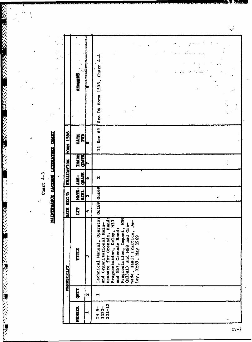
A 2.4.3.6 The Maintenance and Reliability Analysis Chart, the PartsAnalysis Chart, and the Maintenance Package Literaturo Chart wereprepared in accordance with USATECOM Reg 750-15.
2.4.3.7 The DTh was e'camined for completeness and accuracy.
2.4.4 Results
2.4.4.1 The maintenance described in the DTM is sufficient to maintainthe test grenade.
2,4.4.2 There was no significant difference between the maintenance,erformed on the test grenade and the control grenade (M62).
2.4.4.3 No significant damage occurred on the test grenadL. and controlgrenade (M62) bodies with the exception of the one test grenade and onecontrol grenade (M62) thrown in the exercises described in paragraphs2.3.2.7 and 2.3.3.8.
2-9
2.4.4.4 Each test grenade and control grenade (M62) that was cleaned of* all foreign matter after each throw normally required less than 1
minute to empty the body. Tools used during this cleaning were aten-penny nail or a screwdriver and needle-nosed pliers.
2.4.4.5 Chart : -3, appendix I, shows the number of times that thegrenade could be reused without cleaning the body of all foreign matterand the maintenance time required to clean the body when maintenance wasperformed.
2.4.4.6 The charts cited in paragraph 2.4.3.6 are contained in
appendix IV.
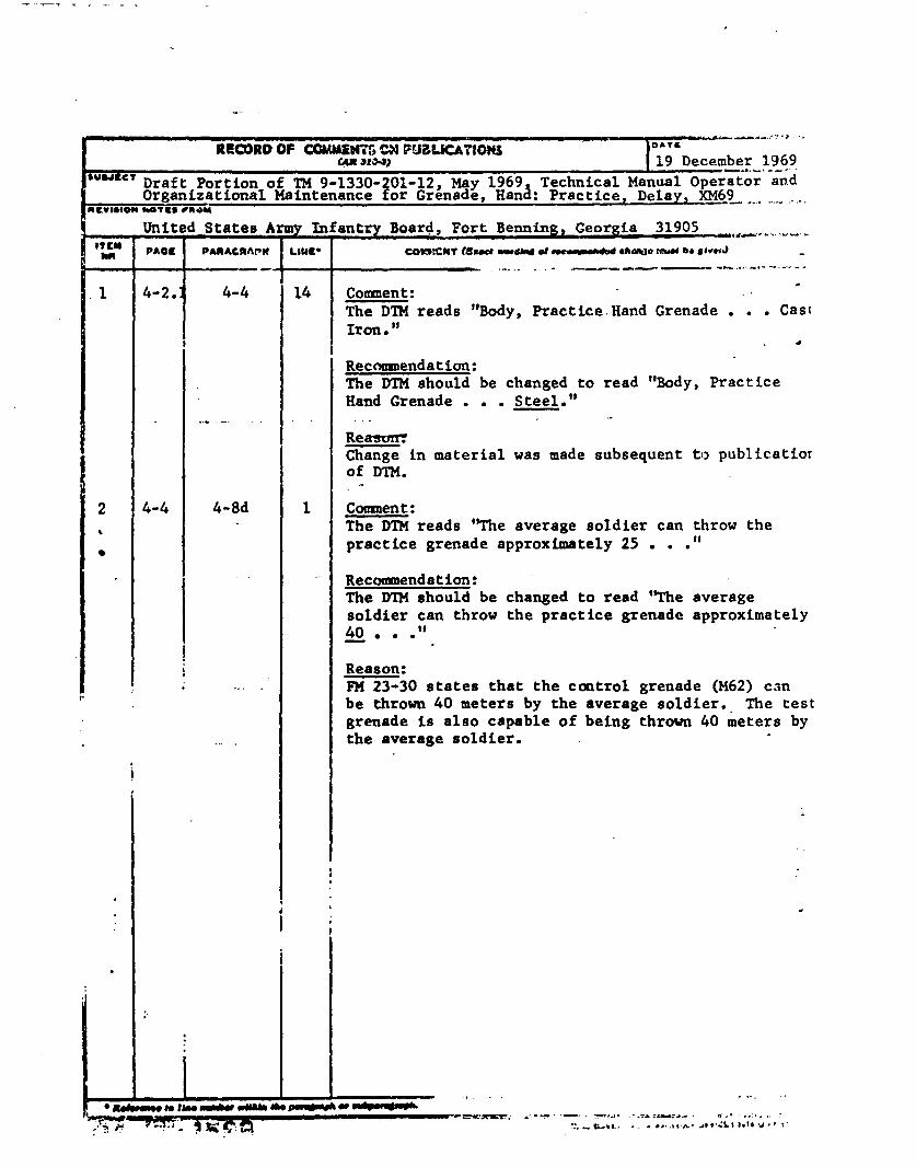
2.4.4.7 The DTM contained the following errors:
a. Paragraph 4-4, Tabulated Data lists the grenade body as castiron. The present test grenade body is steel.
b. Paragraph 4-8d states that the average soldier can throw thetest grena(e approximately 25 meters. FM 23-30 states that the controlgrenade (M62) can be thrown 40 meters by the average soldier. Thetest grenade is also capable of being thrown 40 meters by the average soldier.
2.4.5 Analysis
2.4.5.1 The test grenade requires no maintenance in excess of thatrequired for the control grenade (M62).
,A 2.4.5.2 The maintenance instructions contained in the DTM are adequate.
2.4.5.3 It appears that when the test grenade body is not cleaned ofall foreign matter after each throw, the grenade body can be reusedfor another 20-25 times before maincenance has to be nerformed to allowthe new fuze to be inserted into the grenade body. It will requireapproximately 20 minutes to perform this maintenance.
2.4.5.4 The DTM should be changed to read that the test grenade bodyis made of steel, and the average soldier should be able to throw the
" test grenade approximately 40 meters. See DA Form 1598, Record ofComments on Publications, contained in appendix IV.
2.5 SUBTEST NO 5, HUMAN FACTORS
2.5.1 Objective
T3 determine suitability of the test item with respect ro thecapabilities, limitations, and habit patterns of the soldier user.
2-10
2.5.2 Criteria
None
2.5.3 Method
2.5.3.1 Ten trainees from the US Army Training Center (USATC), FortBenning, Georgia, were used for this exercise. The 10 trainees (7right-handed and 3 left-handed) were given A 1-hour block of instructionto familiarize them with the test grenade. The test officer then split
4, the ten trainees into two 5-man groups to run the grenade assault course.The course consisted of 6 stations each depicting a different tacticalsituation which required the trainees to use different positions andthrowing techniques. They were required to throw a total of 12 practicegrenades (without powder charge and plastic plug) throughout the conductof the course. Current practice at USATC, due to a shortage of fuzes forthe M62 prarcice grenade, was to throw only 2 of the 12 practice grenadeswith fuzes. The remaining 10 were the grenade body only. The same procedurewas utilized for this exercise. The first group of 5 traibees ran theassault course using the control grenade (M62), and again with the testgrenade. The second group ran the assault course first using the testgrenade and then with the control grenade (M62). Both groups weregraded by the instructors from the hand grenade committee while runniugthe assault course. Upon completion of the assault course, both groupsmoved to the live grenade throwing area and each trainee threw twoM67 and two M61 fragmentation grenades. The test project officer andNCO observed the trainees during the running of the assault course andthe live grenade throwing and interviewed each trainee uoon completionof testing.
2.5.3.2 Six test soldiers each threw 9 control grenades (M167) at atarget placed 40 meters to their front. The test soldiers were interviewedby the test officer upon completion of the test to determine their reactionto the use of the XM69 as a practice version for the control grenade (M67)and to detect any differences between the two grenades.
2.5.3.3 During all testing, observations were made by t)' test officerand NCO to determine ease of arming, handling, throwin,, ease ofidentifying the point of impact based on smoke and noise, effectivenessof safety features, replacement of components, and compatibility ofthe test grenades and control grenades (M62) with the skills and limita-tions of the trainees and test soldiers.
2.5.4 Results
2.5.4.1 There was no significant difference between the scores thetrainees received while running the grenade assault course with the testgrenade and with the control grenade (M62) (see chart 3-4, app I).
2-11
-. A
N '
2.5.4.2 When interviewed by the test officer, each trainee commented:a. That the sound and smoke from the test grenade %!n, greater than
that of the control grenade (M62) when used without powder charge andplastic plug.
b. That the test grenade did look and feel the same as the M67fragmentation hand grenade, and use of it prior to throwing the M67 didproperly prepare them to throw the M67.
c. That the test grenade was easier to hanle and throw than thecontrol grenade (M62).
2.5.4.3 The test soldiers commented that the )M69, with the exceptionof color and markings and high explosive filler, is the same as thecontrol grenade (M67) and its use prepared them properly to throw the
* -" control grenade (M67).
2.5.4.4 During all testing, no derogatory comments or observationswere made concerning the test item.
2.5.5 Analysis
The test grenade is suitable with respect to the capabilities,limitations, and habit patterns of the soldier user.
a. -
2.6 SUBTEST NO 6, VALUE ANALYSISe,.
2.6.1 Objective
To determine whether the test grenade has any unnecessary, costly,
or "nice-to-have" features which could be eliminated without adverselyaffecting its performance, reliability, and/or safety.
2.6.2 Criteria
None
2.6.3 Method
2.6.3.1 During the conduct of all subtests observations were made todetect any nonessential or "nice-to-have" features which might havebeen modified or eliminated without compromising the effectiveness orsafety of the test grenade.
2-12
|-S
2.6.3.2 One test soldier detonated 10 test grenades and 10 controlgrenades (M62) without powder charge and plastic plug. The detonationfrom each of these test grenades and control grenades (M62) was observedand photographed with a high speed camera. Six test soldiers were placed40 meters away from the point of detonation to observe the signature effects.
2.6.3.3 The test officer and NCO observed the detonation of the grenadesthrown in paragraph 2.6.3.2 and the detonation of all other grenades thrownwith powder charge and plastic plug during all testing. The photographs
. of the detonation of the test grenades with powder charge and plasticplug taken during Subtest No 3, paragraph 2.3.3.3, and the photographstaken during the exercise conducted in paragraph 2.6.3.2, were comnared.
2.6.4 Results
2.6.4.1 During all testing no nonessential or "nice-to-have" featureswere found, with the exceptio of the powder charge and plastic plugdescribed below.
2.6.4.2 A comparison of the photographs taken with a high speed cameramentioned in paragraph 2.6.3.3 and observations by the test officer, NCO,and'6 test soldiers revealed that the test grenades and control grenades(H62), when thrown without the powder charge and plastic plug, achievethe same results as those grenades thrown with the powder charge andplastic plug.
2.6.5 Analysis
2.6.5.1 The powder charge and plastic plug are considered to be non-essential items and should ?-- deleted as components of the test item.
2.6.5.2 No other nonessential or "nice-to-have" items were noted onthe test item.
2-,1
.
Ile
SECTION 3. APPENDICES,
APPENDIX I. TEST DATA
CHART 3-1
Fuze Functioning Times of Test Grenade and Control Grenade (M62)
(Times Recorded with Stop Watch)
Control Grenade (M62) Test Grenade (XM69)
Time.Te Frequency
4.0 seconds 0 4.0 seconds 0
4.1 1 4.1 24.2 0 4.2 4
4.3 0 4.3 4
4.4 1 4.4 14
4.5 6 4.5 71
4.6 0 4.6 114
4.7 1 4.7 105
4.8 4 4.8 182
4.9 101 4.9 110
5.0 315 .. 0 72
5.1 5 5.1 0
TOTAL GRENADES 434 678
AVERAGE TIME 4.96 seconds 4.74 seconds
I-1
CHART 3-2
Fuze Functioning Times of Test Grenade
(Times Recorded with Visicorder)
Test Grenade (XM69)
Time Frequency
4.0 seconds 0
4.1 0
4.2 0
4.3 1
4.4 4
4.5 28
4.6 77
4.7 86
4.8 61
4.9 19
5.0 4
TOTAL GRENADES 280
AVERAGE TIME 4.67 seconds
1-2
H. CART 3-3
XM169 Practice Hand Grenade
Reuse 300 Times (without powder bag and plastic plug)
Maintenance Time to EmptyThrow _AlI _ orgi.natter Tools Used
1 - 72 24 minutes Screwdriver and Needle-Nosed Pliers.,
73 - 106 23 minutes
107 -133 23 minutes
134 - 157 22 minutes
158 - 178 18 minutes
179 - 201 14 minutes
202 - 227 19 minutes
227 - 274 25 minutes
274 - 300 13 minutes
1-3
a.a
CHART 3-4
Results of Grenade Assault Course
Trainee's Name Score w/XM69 Score w/M62 Total Possible Score
NUNN 36 36 60
DIXON 45 43 60
BOOKER 34 42 60
JAEGERS 27 30 60
JONES 43 39 60
NESMITH 32 40 60
BURKE 34 36 60
ORR 42 37 60
CALHOUN 39 45 60
SAPP 36 24 60
TOTAL 368 372
AVERAGE SCORE 36.8 37.2
1-4
fU
~ ~renade, Hand, Practice, XH69
tI..
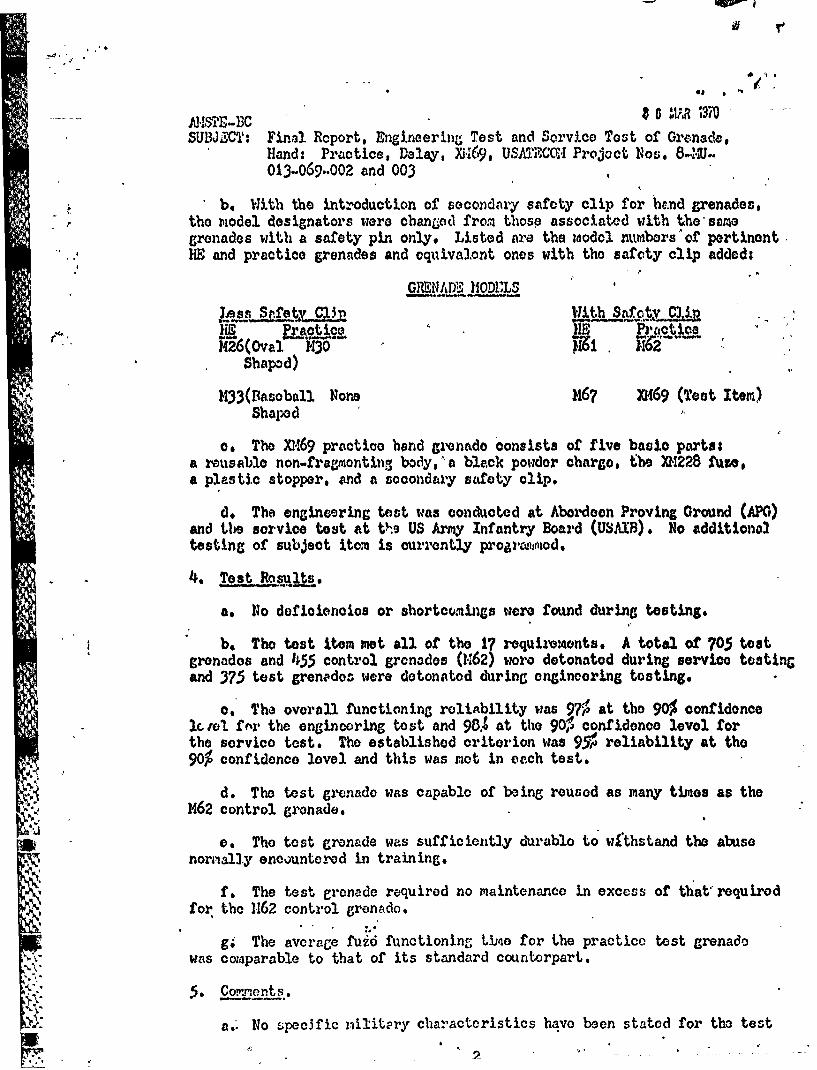
Componenen ade, and, Practice, XM69
Left to right: XM228 Fuze, Safety Clip, BodyPowder Charge, and Plastic Stopper.
Figure 1
1-5
*_.nrz,. c±~, - Ar .r2srrrA,..x.'W'tr, ~rrrs~rurn r, rfrArarTV 7 2VWfl T3Tr..krjt3a'm~rn'n~1w. ~aW~
-4
-4
4-4
0
*~ I
'4
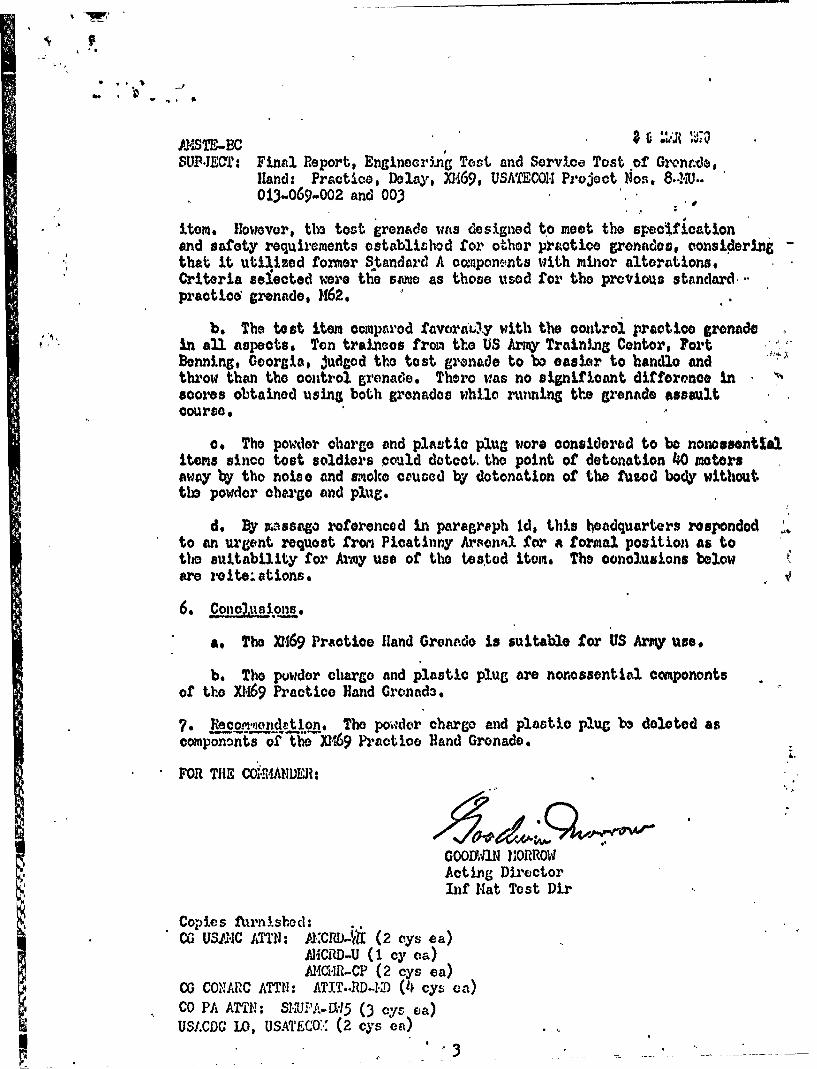
''A Figure 2 ..., ,~ -
4I.
Grenade, Hand: Fragmentation, Delay, H67
jA
* 1-6
k _
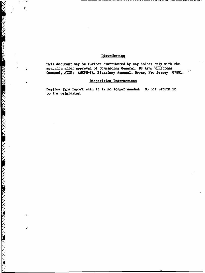
A -* Stie frmnwfz cretyaind
B~~~~~~~~~~~~- -, Stie rmafntoa fzcretyaind
A - Striker fthatne fze orrnctlyalgnd
The arrow on Striker C points to the area where the proner angle is not formed.
* The arrowV on Strikers A and B3 point to the required nroner angle.
Figure 4
Shattered control grenade (M62) after 2 throwsagainst a concrete wall.
~ 1-8
1-
0 0) 0 4 0) 0 0) 0 0.v 4 w -4 En N v. *rNCAC4 n4 M 4 XC4 to4
0 d 0 to I 0 cc 0 0o I . 0 0 t
0,0 N N CfN CIN UN 44~ C14 N 4
to L4 to u o 0'
.40to u
w4 v4 -.4i'
4 14%
0 &J. .a) 1.4 1 1 0Jo*~ 4.)4k ~ I'V .0C0 -4 0 4.00
(d Ai a ~ 41 93% u6
10 1o V 0 0 "4 0)8 bhA .I. I1- VA 44o u 1V0 4.9 UJ a00 0%' 4
0: 60 $44 01. 1: 0V
41 V04 Ci .04 ,
r.14 wa 410' a44 0 1 004
u~~~~0 0d9 0 r -0.4 41 U 4) 00 00 a 01
0 4) 'V 4.1 4i0 000 Id toaw t 0 v FA0 *a a) 41 41 104 1 0 0
u3 440 00 r .801. 0140 a- 1i 01
0 0 0 '.- o00 0 . ' U- ~. 4)941 4
14- -4 a 4) w v .- 4 wN w( a
t 4 v4b w v CL0 4 0 0 t 0 41C
U 4) -A 4J ca . 1 04o to 0 )b 4 4 0 P0 -A -A H 0 cc
1. 4 N . LI %-4 1- 1 1P- P
APPENDIX III. DEFICIENCIES AND SHIORTCOMINGS
None
-.
I.
' APPENDIX IV. MAINTENANCE EVALU ATION95A.
S:s I
.M
SI .
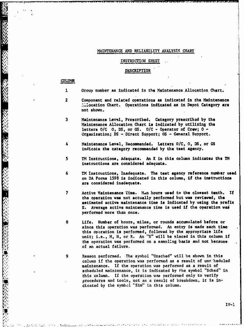
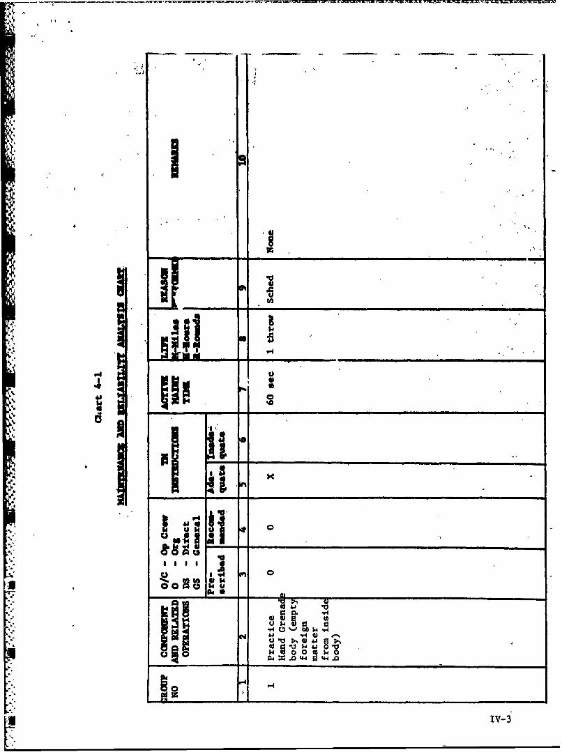
MAINTENANCE AND RELIABILITY ANALYSIS CHART
INSTRUCTION SHEET
DESCRIPTION
COLUM. •
1 Group number as indicated in the Maintenance Allocation Chart.
2 Component and related operations as indicated in the Maintenance: .zIocation Chart. Operations indicated as in Depot Category arenot shown.
3 Maintenance Level, Prescribed. Category prescribad by theMaintenance Allocation Chart is indicated by utilizing theletters O/C O, DS, or GS. O/C - Operator of Crew; 0 -
Organization; DS - Direct Support; GS - General Support.
4 Maintenance Level, Recommended. Letters O/C, 0, DS, or GSindicate the category recommended by the test agency.
5 TM Instructions, Adequate. An X in this column indicates the THinstructions are considered adequate.
6 TM Instructions, Inadequate. The test agency reference number used
on DA Forms 1598 is indicated in this column, if the instructionsare considered inadequate.
7 Active Maintenance Time. M4n hours used to the closest tenth. Ifthe operation was not actually performed but was reviewed, the
Yestimated active maintenance time is indicated by using the prefixE. Average active maintenance time is used if the operation wasperformed more than once.
8 Life. Number of hours, miles, or rounds accumulated before orsince this operation was performed. An entry is made each timethis operation is performed, followed by the appropriate lifeunit; i.e., M, H, or R. An "S" will be placed in this column ifthe operation was performed on a samol-ng basis and not becauseof an actual failure.
9 Reason performed. The symbol "Unsched" will be shown in thiscolumn if the operation was performed as a result of unF+heduledmaintenance. If the operation was performed as a result ofscheduled maintenance, it is indicated by the symbol "Sched" inthis column. If the operation was performed only to verifyprocedures and tools, not as a result of breakdown, it is in-dicated by the symbol "Sim" in this column.
IV-1
- ~-7
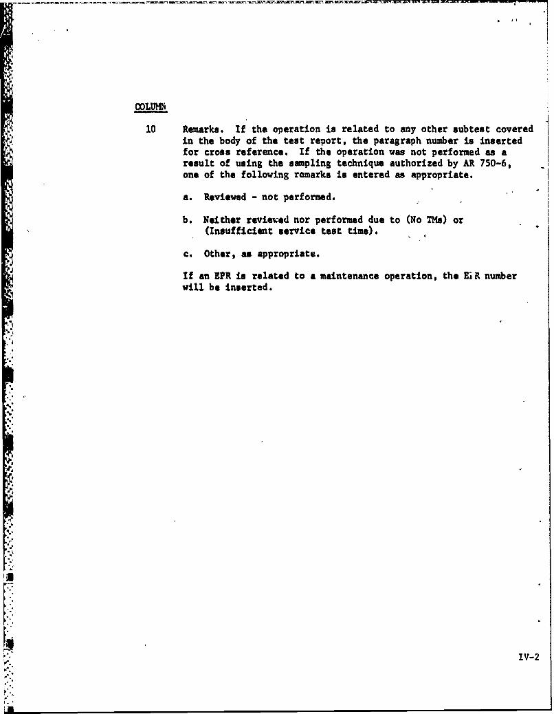
COLUMN
10 Remarks. If the operation is related to any other subtest coveredin the body of the test report, the paragraph number is inserted
for cross reference. If the operation was not performed as aresult of using the sampling technique authorized by AR 750-6,one of the following remarks is entered as appropriate.
a. Reviewed - not performed.
b. Neither reviewed nor performed due to (No TMs) or(Insufficient service test time).
c. Other, as appropriate.
If an EPR is related to a maintenance operation, the EiR numberwill be inserted.
IV-2
ataid
IOU
00811 ___ ___ _
94 U Ujq 10 41I~~ C __ _ _ _ _ _ _ __ _ _ _ _ _
I.-
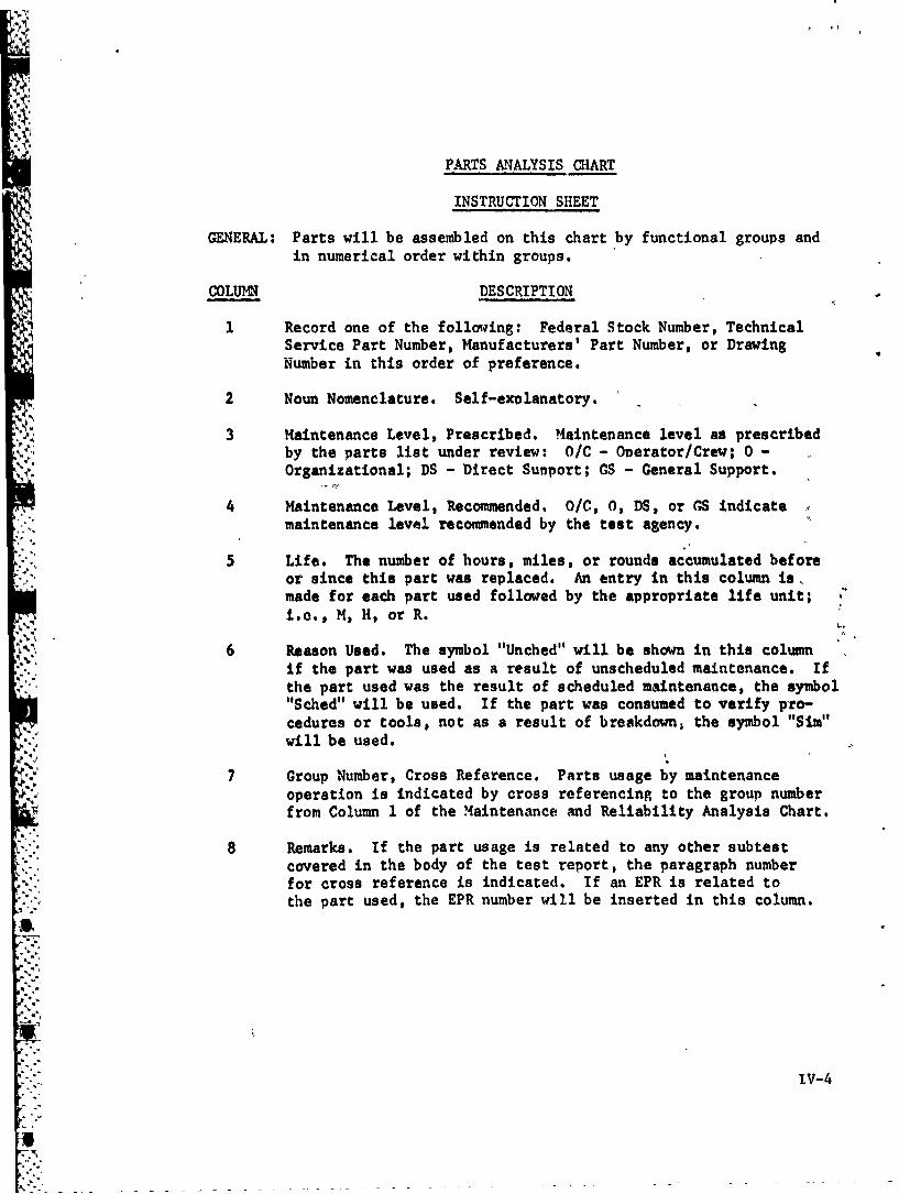
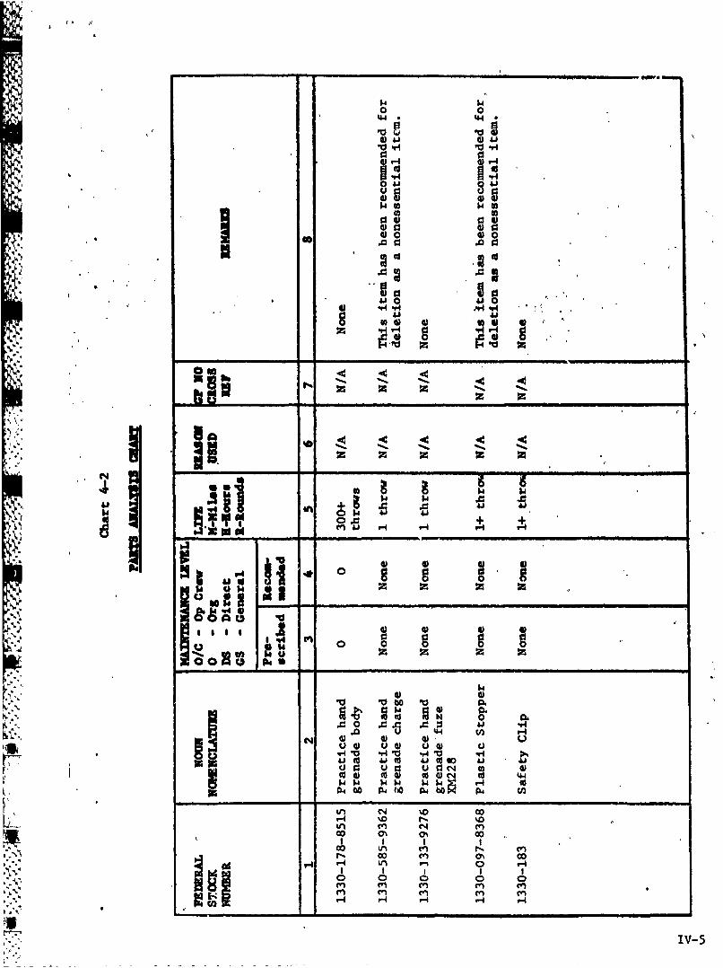
PARTS ANALYSIS CHART
INSTRUCTION SHEET
GENERAL: Parts will be assembled on this chart by functional groups andin numerical order within groups.
COLUMN DESCRIPTION
1 Record one of the following: Federal Stock Number, TechnicalService Part Number, Manufacturers' Part Number, or DrawingNumber in this order of preference.
2 Noun Nomenclature. Self-explanatory.
3 Maintenance Level, Prescribed. Maintenance level as prescribedby the parts list under review: O/C - Overator/Crew; 0 -
Organizational; DS - Direct Support; CS - General Support.
4 Maintenance Level, Recommended. O/C, 0, DS, or GS indicatemaintenance level recommended by the test agency.
5 Life. The number of hours, miles, or rounds accumulated beforeor since this part was replaced. An entry in this column is,made for each part used followed by the appropriate life unit; .
i.e., M, H, or R.
6 Reason Used. The symbol "Unched" will be shown in this columnif the part was used as a result of unscheduled maintenance. Ifthe part used was the result of scheduled maintenance, the symbol"Sched" will be used. If the part was consumed to verify pro-
cedures or tools, not as a result of breakdown, the symbol "Sim"will be used.
7 Group Number, Cross Reference. Parts usage by maintenance"4. operation is indicated by cross referencing to the group number
from Column 1 of the Maintenance and Reliability Analysis Chart.
8 Remarks. If the part usage is related to any other subtestcovered in the body of the test report, the paragraph numberfor cross reference is indicated. If an EPR is related tothe part used, the EPR number will be inserted in this column.
3.
'" ""IV-4
0044.4
Ai4 4)1.
0 41 04114 O 4
1.4
ON
~ 410
$4w
v~0.0
z be
4 - x ~ x
.0 0.4
4) toU to 4) 1 co 4
H4 * o P4ho 046
0% 00
0 0
r"4
I; N 0) 0) 0).
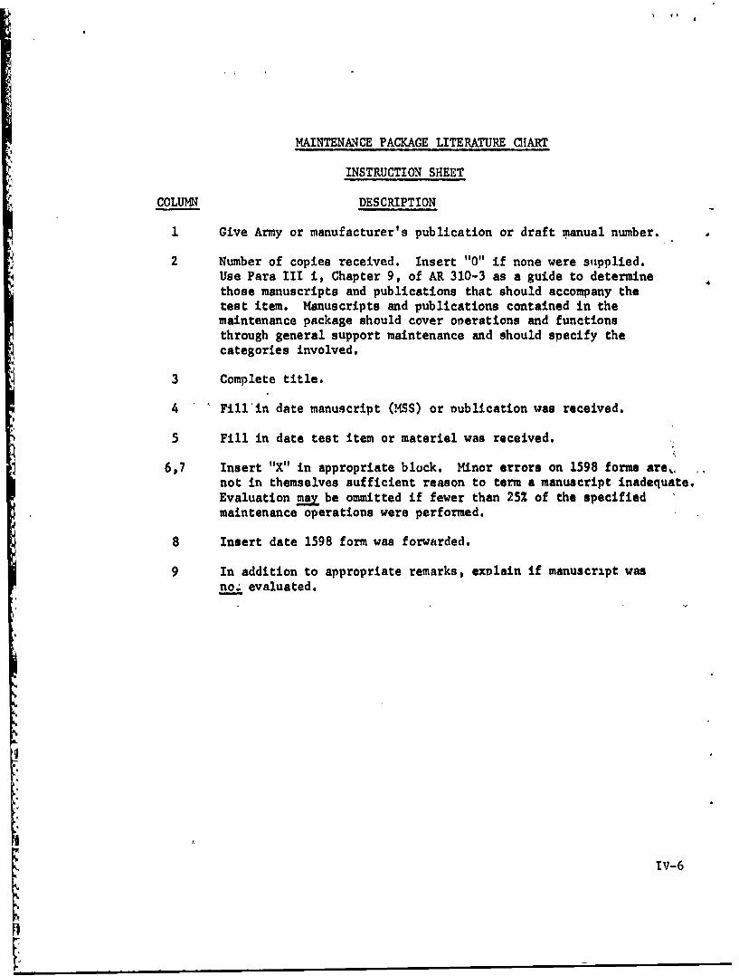
MAINTENANCE PACKAGE LITERATURE CHART
INSTRUCTION SHEET
C, COLUMN DESCRIPTION
1 Give Army or manufacturer's publication or draft manual number.
2 Number of copies received. Insert "0" if none were supplied.Use Para III i, Chapter 9, of AR 310-3 as a guide to determinethose manuscripts and publications that should accompany thetest item. Manuscripts and publications contained in themaintenance package should cover oi erations and functionsthrough general support maintenance and should specify thecategories involved.
3 Complete title.
4 Fill in date manuscript (MSS) or Dublication was received.
5 Fill in date test item or materiel was received.
6,7 Insert "X" in appropriate block. Minor errors on 1598 forms are,not in themselves sufficient reason to term a manuscript inadequate.Evaluation may be ommitted if fewer than 25% of the specifiedmaintenance operations were performed.
8 Insert date 1598 form was forwarded.
9 In addition to appropriate remarks, exolain if manuscript wasnoz evaluated.
i.
{r IV-6
41*0
Ia
r- -0 -4%
1d cc "4
.4. 1
to 4j 4 1j1
,H N U 4% -w0 w~ N z I
040r-4%
ONO I0
N "~~~4 N. ~ . .
f404Jo4Ja
RRD DOF CO"r MPZLCTOSDYC19 December 1969
$SW9CT Draft Portion of TM 9-1330-201-12, May 1969 Technical Manual Operator and
Organizational Maintenance for Grenade, Hana: Practice, Delay, XM69NZ.VIIt@ h@YUUI V R*
United States A yInfantry Board, Fort Bening,_Georgia 31905PA@I PA IA CR AP LIU 96 C GOD C NT (Bu MI uWe W O t #.. addb d dh .ljo f.WW be #V,.')
1 4-2.i 4-4 14 Comment:
The DTM reads "Body, Practice.Hand Grenade . . . Cast
Iron."
Recommendation:The DTM should be changed to read "Body, PracticeHand Grenade . . . Steel."
Reas rs.Change in material was made subsequent to publicatiorof DTM.
2 4-4 4-8d 1 Comment:The DTM reads "The average soldier can throw thepractice grenade approximately 25 . .
Recommendation:The DTM should be changed to read "The average
soldier can throw the practice grenade approximately40 . .
Reason:
FM 23-30 states that the control grenade (M62) canbe thrown 40 meters by the average soldier. The test
grenade is also capable of being thrown 40 meters by
the average soldier.
Re 06 #mIe N aaf me Dm~ AVSeIh• ..,...t....a..- --..- a *'."
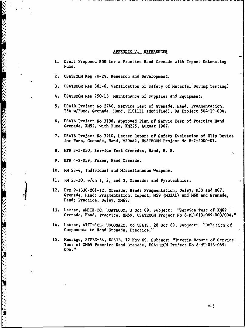
APPENDIX V. REFERENCES
1. Draft Proposed SDR for a Practice Hand Grenade with Impact DetonatingFuze.
2. USATECOM Reg 70-24, Research and Development.
3. USATECOM Reg 385-6, Verification of Safety of Materiel During Testing.
4. USATECOM Reg 750-15, Maintenance of Supplies and Equipment.
5. USAIB Project No 2746, Service Test of Grenade, Hand, Fragmentation,T54 w/Fuze, Grenade, Hand, TlOllEl (Modified), DA Project 504-19-004.
6. USAIB Project No 3196, Approved Plan of Servie Test of Practice HandGrenade, XM52, with Fuze, XM225, August 1967.
7. USAIB Project No 3210, Letter Report of Safety Evaluation of Clip Device
for Fuze, Grenade, Hand, M204A2, USATECOM Project No 8-7-2000-01.
8. MTP 3-3-030, Service Test Grenades, Hand, H. E.
9. MTP 4-3-059, Fuzes, Hand Grenade.
10. FM 23-4, Individual and Miscellaneous Weapons.
11. FM 23-30, w/ch 1, 2, and 3, Grenades and Pyrotechnics.
12. DTM 9-1330-201-12, Grenade, Hand: Fragmentation, Delay, M33 and M67,iGrenade, Hand: Fragmentation, Impact, M59 (M33A1) and M68 and Grenade,
Hand; Practice, Delay, XM69.
13. Letter, AMSTE-BC, USATECOM, 3 Oct 69, Subject: "Service Test of XM69Grenade, Hand, Practice, XM69, USATECOM Project No 8-Mi-013-069-003/004."
14. Letter, ATIT-SCL, USCONARC, to USAIS, 28 Oct 69, Subject: "Deleti:n cfComponents to Hand Grenade, Practice."
15. Message, STEBC-SA, USAIB, 12 Nov 69, Subject: "Interim Report of ServiceTest of XM69 Practice Hand Grenade, USATECOM Project No 8- C-013-069-004."
V-4
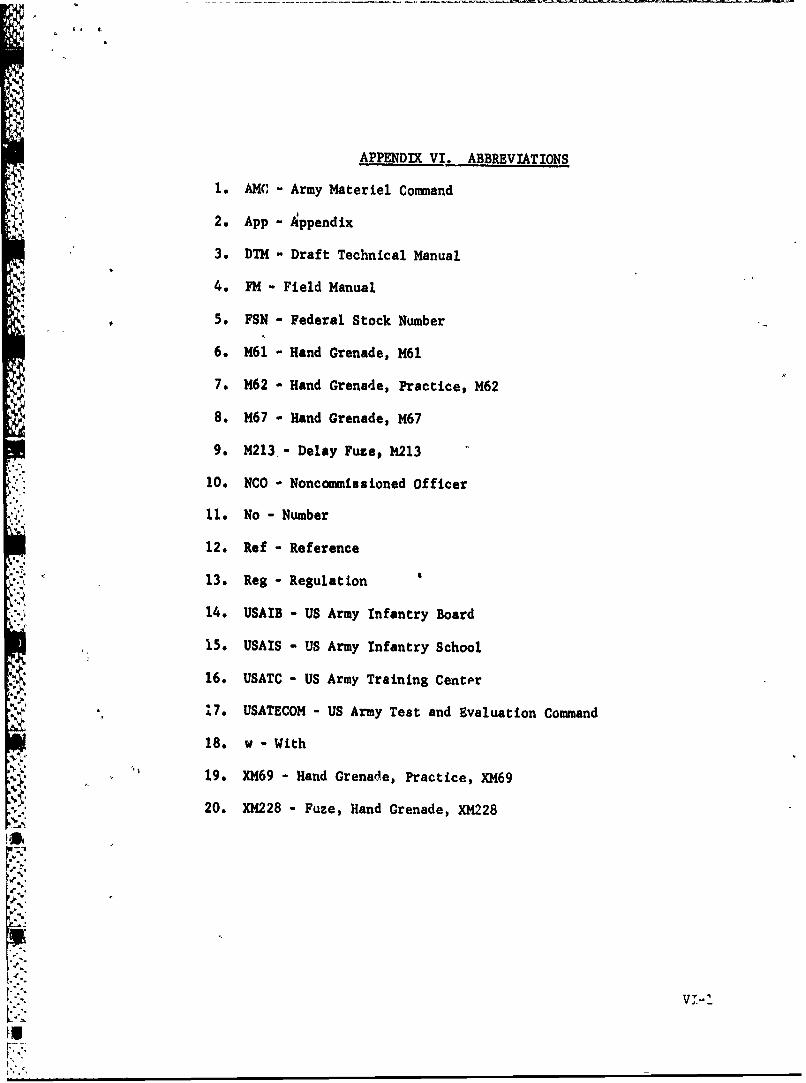
APPENDIX VI. ABBREVIATIONS
1. AMC - Army Materiel Command
2. App - Appendix
3. DTM - Draft Technical Manual
4. FM - Field Manual
5. FSN - Federal Stock Number
6. M61 - Hand Grenade, M61
7. M62 - Hand Grenade, Practice, M62
8. M67 - Hand Grenade, M67
9. M213,- Delay Fuze, M1213
10. NCO - Noncommissioned Officer
K'. 11. No - Number
12. Ref - Reference
13. Reg - Regulation
14. USAIB - US Army Infantry Board
15. USAIS - US Army Infantry School
16. USATC - US Army Training Center
17. USATECOM - US Army Test and Evaluation Command
18. w - With
19. XM69 - Hand Grenade, Practice, XM69
20. XM228 - Fuze, Hand Grenade, XM228
I-I-s
VV-
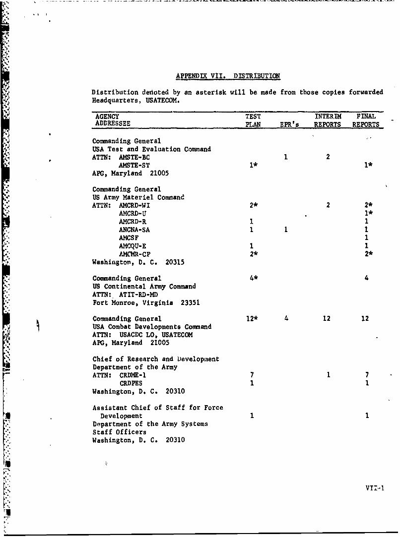
APPENDIX VII. DISTRIBUTION
Distribution detioted by an asterisk will be made from those copies forwardedHeadquarters, USATECOM.
AGENCY TEST INTERIM FINAL
ADDRESSEE PLAN EPR's REPORTS REPORTS
Commanding GeneralUSA Test and Evaluation CommandATTN: AMSTE-BC 2
AMSTE-ST 1* 1*APG, Maryland 21005
Commanding GeneralUS Army Materiel CommandATTN: AMCRD-WI 2* 2 2*
AMCRD-U 1*AMCRD-R 1 1ANCNA-SA I 1 1AMCSF 1AMCQU-E 1 1AMCMR-CP 2* 2*
Washington, D. C. 20315
Commanding General 4* 4US Continental Army CommandATTN: ATIT-RD-MDFort Monroe, Virginia 23351
Commanding General 12* 4 12 12USA Combat Developments CommandATTN: USACDC LO, USATECOMAPG, Maryland 21005
Chief of Research and Development
Department of the ArmyATTN: CRDME-l 7 7
CRDPES 1 1Washington, D. C. 20310
Assistant Chief of Staff for ForceDevelopment 1 1
Department of the Army SystemsStaff OfficersWashington, D. C. 20310
vTIi-
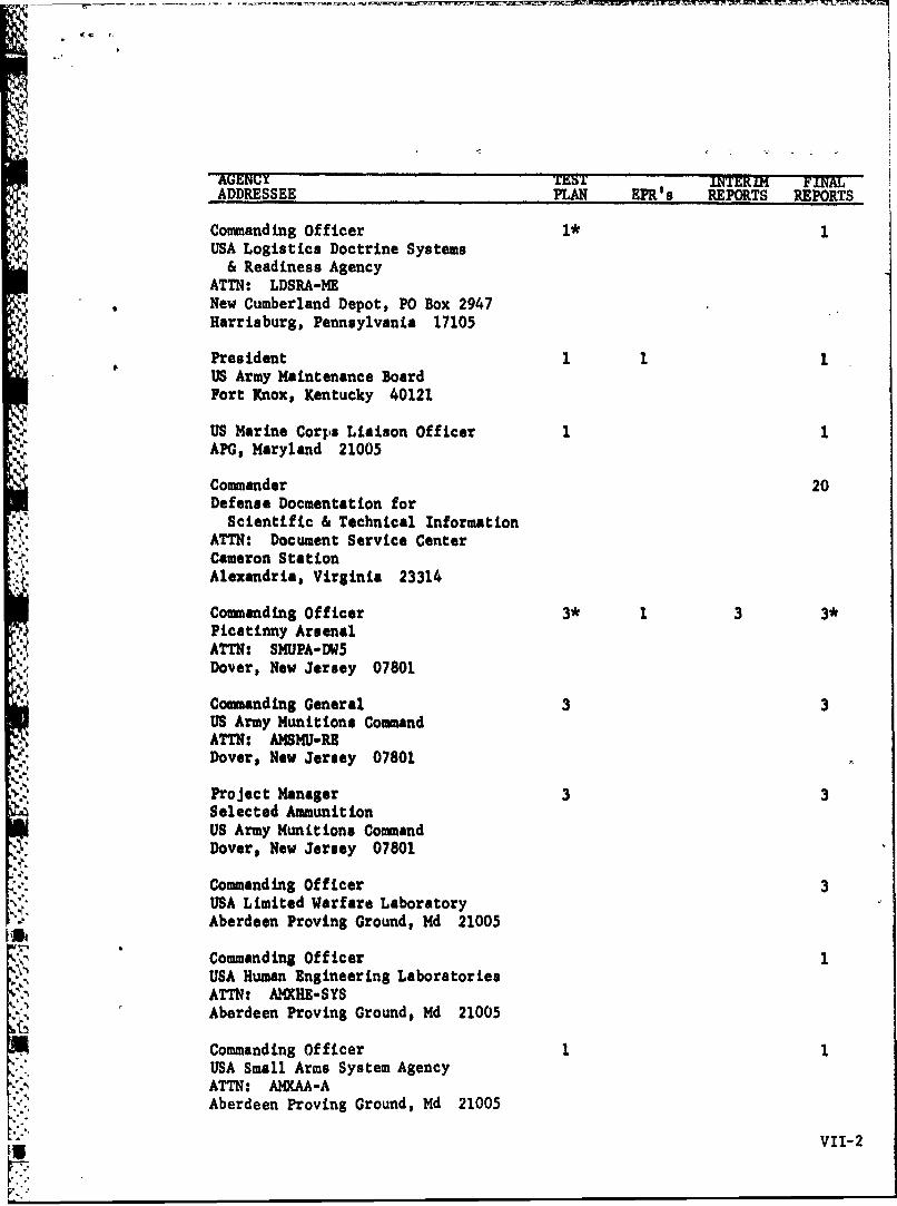
A (C TEST ERI Fm=
ADDRESSEE PLAN EPR's REPORTS REPORTS
Commanding Officer 1* 1USA Logistics Doctrine Systems& Readiness Agency
ATTN: LDSRA-MENew Cumberland Depot, PO Box 2947Harrisburg, Pennsylvania 17105
PresidentUS Army Maintenance BoardFort Knox, Kentucky 40121
US Marine Corps Liaison OfficerAPG, Maryland 21005
Commander 20Defense Docmentation forScientific & Technical Information
ATTN: Document Service CenterCameron StationAlexandria, Virginia 23314
Commanding Officer 3* 1 3 3*Picatinny ArsenalATTN: SMUPA-DW5Dover, New Jersey 07801
Commanding General 3 3
US Army Munitions CommandATTN: AMSMU-REDover, New Jersey 07801
. Project Manager 3 3
Selected AmmunitionUS Army Munitions CommandDover, New Jersey 07801
Commanding Officer 3USA Limited Warfare LaboratoryAberdeen Proving Ground, Md 21005
Commanding Officer 1USA Human Engineering Laboratories
ATTN: AMXHE-SYSAberdeen Proving Ground, Md 21005
Commanding OfficerUSA Small Arms System AgencyATTN: AMXAA-AAberdeen Proving Ground, Md 21005
VII-2
UNCLASSIFIEDSecuity Classification
DOCUMENT CONTROL DATA - R&D(Securit classification of title, body of abstract and indexing annotation must be entered when the overall report to cleallied)
1. ORI €INATIN f ACTVITY (Convorate author) a. REPORT SCURITY C LASSIICATION
United States Army Infantry Board UNCLASSIFIED
Fort Benning, Georgia 31905 2b. GROuP
3. REPORT TITLE
Service Test of XMY69 Practice Hand Grenade
4. DOCRIPTIVl[ NOTES (Tp*M of #spat and Melmaive dale*)Final Report. December 1969
S. AUTkOR(S) (Last name. Sire amnt a /. ,ntil
Marnon, Donald J. Major
A6. REPO RT DATE 7a. TOTAL NO. OF PAGS lb'. NO. OP REP8
faepmbpr 1969 48 15I. CONTRACT OR GRANT NO. Ia. ORIGINATOR's REPORT NUibe(I)
SPno..e wo. USATECOM Project No 8-MU-013-069-004
a. *b. g7 NER~WORT NOMS (4my edw Aeinbe Moat mopy be assigned
d. USAIB Project No 3297I& AVA ILAILIT/LIMOTATM4 oTICE8
Destroy this report when it is no longer needed, Do not return it' to theoriginator.
11. SUPPLEMENTARY NOTES It. SPONSORING WLITARY ACTI'VITY
Comlanding General, US Amy MunitionsCommand, ATTh: AMCPA-SA, Picatinny ArsenalDover, N, J. 07801
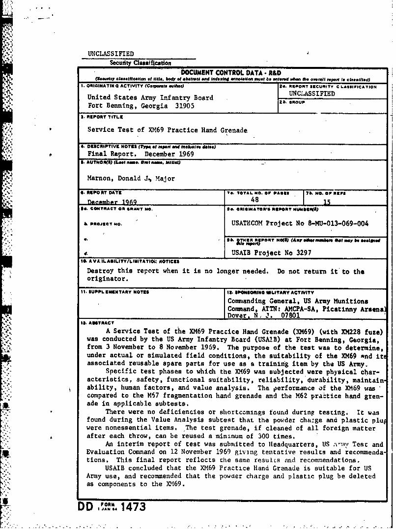
A~. It. AINSTRACTA Service Test of the XM69 Practice Hand Grenade (XM69) (with XM228 fuze)
was conducted by the US Army Infantry Board (USAIB) at Fort Benning, Georgia,from 3 November to 8 November 1969. The purpose of the test was to determine,under actual or simulated field conditions, the suitability of the XM69 And iteassociated reusable spare parts for use as a training item by the US Army.
Specific test phases to which the XM69 was subjected were physical char-acteristics, safety, functional suitability, reliability, Curability, maintain'ability, human factors, and value analysis. The performance of the XM69 wascompared to the M57 fragmentation hand grenade and the M62 practice hand gren-ade in applicable subtests.
There were no deficiencies or shortcomings fournd during testing. It wasfound during the Value Analysis subtest that the powder chitge and plastic pluwere nonessential items. The test grenade, if cleaned of all foreign matterafter each throw, can be reused a minimum of 300 times.
An interim report of test was submitted to Headquarters, US : , Test andEvaluation Command on 12 November 1969 giving tentative results and recommenda-tions. This final report reflects the same resuLcq and recommendations.
USAIB concluded that the XM69 Practice Hand Grenade is suitable for USArmy use, and recommended that the powaer charge and plastic plug be deletedas components to the X)069.
D D JoN 1473
UNCLASSIFIEDSecurity Classification
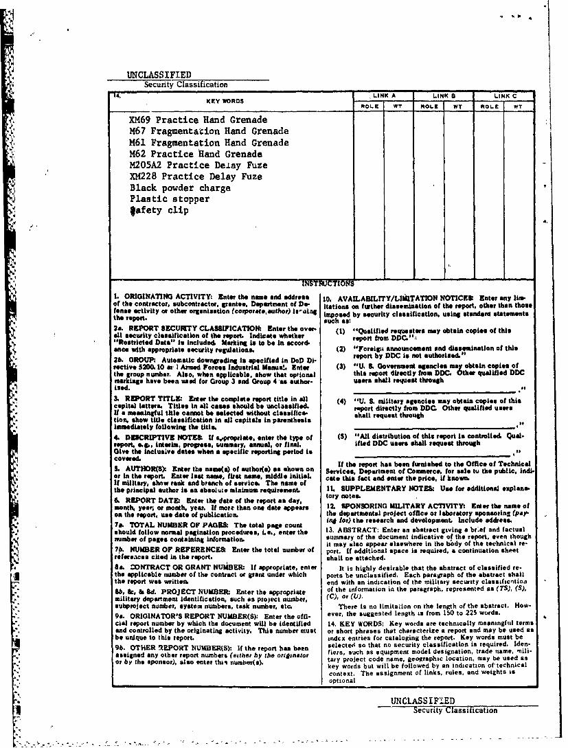
14. LINK A LINK S LINK CKEY WORDS .. ....ROLE WT ROLE WT ROLE WT
XM69 Practice Hand GrenadeM67 Fragmentation Hand GrenadeM61 Fragmentation Hand GrenadeM62 Practice Hand GrenadeM205A2 Practice Delay FuzeXM228 Practice Delay FuzeBlack powder chargePlastic stopperlafety clip
J4
INSTRJCTIONi
1. ORIGINATING ACTIVITY: Enter the name and address I0. AVAILABILITY/LII[TATION NOTICES: Eater any lim-of the contractor, subcontractor, grante, Department of Do- itations on further dissemination of the report, other than thoseenase activity or other orgeanisaton (corporate, author) is-lng imposed by security classification. using standard statements
the report. such as:
2a. REPORT SECU ITY CLASSIFICATION: Enter the over- (1) "Qualified requesters my obtain copies of thisall security classification of the report. Indicate whether report from DDC."Restricted Data" Is included, Marking Is to be In accord.ance with appropriate security regulations. (2) "Foreigoa announcement and dissemination of this2b. GROUP: Automatic downading is specified In DoD Di- report by DDC Is not authorized."
rective 5200.10 at I Armed Forces Industrial Manua!. Enter (3) "U. S. Government agencies may obtain copies ofthe group number. Also, when applicable, show that optional this report directly from DDC. Other qualified DDCmakings have been used for Group 3 and Group 4 'as author- users shall request through
"i ied.3. REPORT TITLE: Enter the complete report title in all (4) "U. S. military agencies may obtain copies of this
* capital letters. Titles in all cases should be unclassified, report directly from DDC Other qualified usersIf a meaningful title cannot be selected without classifica- shall request throughtion, show title classification In all capitals in parenthesis h r e rimmediately following the title. ',._,
4. DESCRIPTIVE NOTES: If a,,proprite, enter the type of (5) "All distribution of this report is controlled. Qial-report. eg., interim, progress, -ummery, annual, or final. ified DDC users shall request throughGive the inclusive dates when a specific reporting period iscovereda If the report has been furnished to the Office of TechnicalS. AUTHOR(S) Enter the name(s)of autboa(s) as shown on Services. Department of Commerce. for sale tu the public. Indl-or in the report. Enter last name, first name, middle InitiaL cate this fact and enter the price, if known.If military, show rank and branch of service. The name ofthe principal author is an absolute minimum requirement. 11. SUPPLEMENTARY NOTES: Use for addiuonal explana-6. REPORT DATE Enter the date of the report as day. tory note.month, year, or month. year. It mortr than one date appears l2. SPONSORING MILITARY ACTIVITY Enter the name ofon the report, use date of publicatku. the departmental project office or laboratory sponsoring (pay
* 7a. TOTAL NUMBER OF PAGE&. The total page count ing for) the research and development. Include address.should follow normal pagination procedures, ie., enter the 13. ABSTRACT: Enter an abstract giving a br.ef and factualnumber of pages containing Information. summary of the document indicative of the report, even though
NEIt may also appear elsewhere in the bdy of the technical re-S7b. NUMBER OF REFERENCES: Enter the total number of port. If additional space is required, a continuation sheetreferences cited in the report. shall oe attached.
III CONTRACT OR GRANT NUiBER: If appropriate, enter It is highly desirable that the abstract of classified re-the applicable number of the contract or grant under which ports be unclassified. Each paragraph of the abstract shallthe report was written. end with an indication of the military security classificaition
lb, Bc, & Sd. PROJECT NUMBER: Enter the appropriate of the information in the paragraph, represented as (TS), (S),
military department identification, such as project number, (C), or (u).subproject number, system numbers, task number, etc. There is no limitation on the length of the abstract. How-9a. ORIGINATOR'S REPORT NUMBER(S): Enter the offi- ever, the suggested length is from 150 to 225 words.
cial report number by which the document will be identified 14. KEY WORDS: Key words are technically meaningful termsand controlled by the originating activity. This number must or short phrases that characterize s report and may be used asbe unique to this report. indcx entries for cataloging the report. Key words must be
9b. OTHER REPORT NUMBER(S): If the report has been selected so that no security classification is required. Iden-
assigned any other report numbers (either by the originator fiers, such as equipment model designation, trade name, 'nili-
or by the sponsor), also enter thin number(s). tary project code name, geographic location, may be used askey words but will be followed by an indication of technicalcontext. The assignment of links, rules, and weights is
L optional
UNCLASSIFIEDi1 Security Classification
" ." ' . . " - _ 2 .. - -" -"- -- .. . . ' - + - " -
-. .. . .
0 u
z c w
IL Z
o ). a00 . o-.S L
01 0
zww 0 41 4
I- t
la i mi 04cS