Embed Size (px)
Citation preview

RDE710
Rotating Electrode
OPERATOR’S MANUAL


iii
Table of Contents 1 Preface 1
1.1 Scope 1
1.2 Copyright 1
1.3 Trademarks 1
1.4 Certifications 1
1.5 Warranty 1
1.6 Specifications 2
1.7 Safety Notices 3
1.8 Notes and Hints 3
1.9 Technical Service Contact 4
1.10 Factory Return Service Address 4
2 Description 5
2.1 Major System Components 7
2.2 Control Unit Components 9
2.3 Motor Unit Components 11
2.4 Typical Rotating Disk Electrode Design 13
2.5 Typical Rotating Ring-Disk Electrode Design 14
3 Installation 15
3.1 Site Preparation 15
3.2 Unpacking and Setting Up the Rotator 15
4 Operation 21
4.1 The Rotating Shaft 21
4.1.1 Installing a Shaft 23 4.1.2 Changing the Tip on a Shaft 26
4.2 Mounting the Cell 28
4.3 The Enclosure 29
4.4 Cell Connections 29
4.4.1 RDE and RCE Wiring 30 4.4.2 RRDE Wiring 31 4.4.3 Routing Cables and Tubing 32 4.4.4 Proper Chassis Grounding 32
4.5 Using the Rotator in a Glove Box 33
4.6 Rotation Rate Control 35
4.6.1 Manual Control of Rotation 35 4.6.2 Monitoring the Rotation Rate 35 4.6.3 External Control of the Rotation Rate 35 4.6.4 External Motor Stop Control 36
4.7 Circuit Protection 37

iv
5 Electrodes 39
5.1 Electrode Handling Precautions 39
5.2 Shafts 41
5.3 RDE Tips 43
5.4 Single-Piece RDE Designs 48
5.5 RRDE Tips 49
5.6 RCE Tips 52
6 Maintenance 53
6.1 Routine Cleaning 53
6.2 Brush Replacement 53
6.2.1 Internal Brush Replacement 53 6.2.2 Complete Brush Assembly Replacement 56
6.3 Lower Bearing Replacement 57
6.4 Removing the Motor-Coupling Assembly 58
6.5 Installing a New Motor-Coupling Assembly 61
6.6 Rotation Rate Calibration 63
6.7 Changing the Input Rotation Rate Ratio 67
6.8 Changing the Motor Stop Signal Logic 70
7 Parts and Accessories 73
7.1 Mechanical Parts and Hardware 73
7.2 Power Cords 75
8 Troubleshooting 77
9 Storage and Shipment 81
10 Theory 82
10.1 Forced Convection 82
10.2 Half Reactions 83
10.3 Voltammetry 84
10.3.1 Voltammogram Plotting Conventions 87 10.3.2 Measuring Limiting Currents 89
10.4 Rotating Disk Electrode (RDE) Theory 91
10.4.1 Levich Study 92 10.4.2 Koutecky-Levich Analysis 94
10.5 Rotating Ring-Disk Electrode (RRDE) Theory 96
10.5.1 Theoretical Computation of the Collection Efficiency 96 10.5.2 Empirical Measurement of the Collection Efficiency 97 10.5.3 Generator/Collector Experiments 98 10.5.4 Comparing Two Competing Pathways 100
10.6 Rotating Cylinder Electrode (RCE) Theory 101
10.7 References 102
11 Glossary 105

v
Table of Figures Figure 1.1: Special Icons Used to Indicate Safety Information .......................................... 3 Figure 1.2: Special Icons Used to Highlight Useful Information .......................................... 4 Figure 2.1: Major Components of the Gamry RDE710 ....................................................... 7 Figure 2.2: Control Unit Front and Back Panels ................................................................. 10 Figure 2.3: Motor Unit Components .................................................................................... 12 Figure 2.4: Typical Rotating Disk Electrode (RDE) Tip with Shaft ..................................... 13 Figure 2.5: Typical Rotating Ring-Disk Electrode (RRDE) Tip with Shaft .......................... 14 Figure 4.1: Contact Areas at Top of Rotating Electrode Shafts ...................................... 21 Figure 4.2: The Brush Chamber (side view) ........................................................................ 22 Figure 4.3: Proper (left) and Improper (right) Shaft Insertion Positions ........................... 25 Figure 4.4: Installing a Tip on to a Shaft .............................................................................. 26 Figure 4.5: Properly Supported and Clamped Electrochemical Cells ........................... 28 Figure 4.6: Enclosure Properly Mounted on All Four Pins .................................................. 29 Figure 4.7: Connection of Counter and Reference Electrodes ...................................... 30 Figure 4.8: Brush Connections for a Rotating Disk Electrode (RDE) or a Rotating
Cylinder Electrode (RCE) ................................................................................... 31 Figure 4.9: Brush Connections for a Rotating Ring-Disk Electrode (RRDE) ..................... 31 Figure 4.10: Routing Cables out of the Enclosure ............................................................... 32 Figure 4.11: Glove Box Configuration ................................................................................... 33 Figure 6.1: An Optical Tachometer with a Traceable Calibration Certificate ............. 62 Figure 6.2: Use of Optical Tachometer with Reflective Target ........................................ 65 Figure 7.1: Standard C18 Connection on Power Entry Module ...................................... 75 Figure 10.1: Response to a Potential Sweep (Cathodic) from a Solution Initially
Containing only the Oxidized Form (O) with no Reduced Form (R) ........... 86 Figure 10.2: Response to a Potential Sweep (Anodic) from a Solution Initially
Containing only the Reduced Form (R) with no Oxidized Form (O) ........... 87 Figure 10.3: A Voltammogram is a Plot of Current versus Potential ................................. 88 Figure 10.4: Two Popular Voltammogram Plotting Conventions ...................................... 88 Figure 10.5: Sloping Backgrounds in Voltammograms ....................................................... 90 Figure 10.6: Voltammogram for a Solution Containing Both O and R ............................. 90 Figure 10.7: Levich Study – Voltammograms at Various Rotation Rates ......................... 93 Figure 10.8: Levich Study – Limiting Current versus Rotation Rate .................................... 93 Figure 10.9: Koutecky Levich Study – Voltammograms with Sluggish Kinetics ............... 94 Figure 10.10: Rotating Ring-Disk Voltammograms at Various Rotation Rates ................... 98

vi

1
1 Preface
1.1 Scope
Gamry’s Rotating Disk Electrode (RDE710) is a solid-state-controlled servo-system
designed to rotate an electrode in an electrochemical cell. This manual
describes the proper use of the RDE710 rotator and covers routine operating
procedures, periodic maintenance and calibration, and safety issues.
The reader of this manual is assumed to have some basic knowledge of
electronics, electrochemistry, and the modern practice of voltammetry. While
some background information is presented in this manual, the reader is referred
to the appropriate scientific literature for more detail regarding the theory and
practice of hydrodynamic voltammetry.
1.2 Copyright
This publication may not be reproduced or transmitted in any form, electronic or
mechanical, including photocopying, recording, storing in an information
retrieval system, or translating, in whole or in part, without the prior written
consent of Gamry Instruments, Inc.
1.3 Trademarks
All trademarks are the property of their respective owners.
1.4 Certifications
This instrument complies with one or more EU directives and bears
the CE marking. See the "CE Declaration of Conformity" attached
to the end of this manual for more details.
1.5 Warranty
The RDE710 is warranted to be free from defects in material and workmanship
for a one year period from the date of shipment to the original purchaser and
when used under normal conditions. The obligation under this warranty is limited
to replacing or repairing any part or parts which shall upon examination disclose
to Gamry Instruments’ satisfaction to have been defective and shall have been
returned freight prepaid and clear of encumbrances to Gamry Instruments in
Warminster, PA U.S.A. within the warranty period. This warranty is offered
expressly in lieu of all other warranties, expressed or implied and all other
obligations or liabilities.

2
1.6 Specifications
All specifications are subject to change without notice.
Power
100 - 240 VAC, +/-10%; 50/60 Hz; 2A
Shipping Information
shipping weight: 60 pounds (25 kg)
shipping dimensions: 24.0 x 24.0 x 24.0 in (61 x 61 x 61 cm)
Dimensions
(L x W x H)
control unit: 11.4 x 10.1 x 5.75 in (29 x 26 x 15 cm)
rotator enclosure: 18.8 x 15.5 x 21.0 in (48 x 40 x 54 cm)
Operating Temperature
10 ºC to 40 ºC (50 ºF to 104 ºF)
Motor
motor power: 15 W
supply voltages: +30 VDC, - 24 VDC
motor type: permanent magnet
Motor Protection
2 Amp thermal-type circuit breaker
current limited power supplies
Max. Continuous Torque
28.3 millinewton-meters
Rate Control
closed loop servo-system
temperature compensated tachometer mounted on motor shaft
Rate Display
4 ½ digit display indicates rotation rate (RPM)
Rate Accuracy
100 to 200 RPM: accurate to within ± 2 counts of display reading
200 to 10,000 RPM: accurate to within ± 1% of display reading
Controls
front panel: 10-turn rotation rate control knob
button to reset circuit breaker
rear panel: power switch
Rotation Rate Input
allows optional external signal to control rotation rate (banana jack)
selectable control ratio: 1 RPM/mV (default)
2 RPM/mV
4 RPM/mV
Rotation Rate Output
allows optional external monitoring of rotation rate (banana jack)
output signal ratio: 1 mV/RPM (+/- 1%)
Rotator Motor Stop
rear panel input optional digital motor stop signal (banana jack)
Earth Ground
metal binding post (banana jack) connects to ground lead of
power cord and to control unit chassis
Common Jacks
DC common (3 black banana jacks), isolated from Earth ground
Slew Rate of Motor
approximately 300,000 RPM/sec maximum (no load)
Bandwidth > 50 Hz, -1 dB
(at 1000 RPM peak to peak modulation on a 2000 RPM base rate)

3
1.7 Safety Notices
Throughout this manual there are safety notices which are indicated with
special icons as shown below (see Figure 1.1). When working with the rotator
and related accessories take heed and abide by all safety warnings. Failure to
do so may result in damage to property, personal injury, or both.
CAUTION:
Indicates information needed to prevent injury or death to a
person or to prevent damage to equipment.
CHEMICAL INCOMPATIBILTY:
Indicates chemical incompatibility information needed to
prevent damage to equipment.
DISCONNECT POWER:
Indicates when the power cord should be disconnected
from the power source prior to performing an operation.
TEMPERATURE CONSTRAINT:
Indicates when an operation or use of an object is limited to
a specified temperature range.
Figure 1.1: Special Icons Used to Indicate Safety Information
1.8 Notes and Hints
Throughout this manual there are highlighted notes and information which are
indicated with special icons as shown below (see Figure 1.2).

4
Note:
Important or supplemental information.
Tip:
Useful hint or advice.
Figure 1.2: Special Icons Used to Highlight Useful Information
1.9 Technical Service Contact
For questions about proper operation of the RDE710 system or other technical
issues, please contact Gamry Instruments directly using the contact information
below:
Gamry Instruments, Inc.
www.gamry.com
Phone: +1 (215) 682-9330
1.10 Factory Return Service Address
In the event that the rotator or one of its components or a related accessory
must be returned to the factory for service, please contact Gamry Instruments
(see contact information above) to obtain a Return Material Authorization
(RMA) number. Include a copy of this RMA in any and all shipping cartons and
ship the cartons to the factory address below:
Gamry Instruments, Inc
734 Louis Drive
Warminster, PA 18974
USA
Phone: +1 (215) 682-9330
Return Material Authorization Required!
Do not ship equipment to the factory address above without first
obtaining a Return Material Authorization (RMA) number from
Gamry Instruments, Inc. Call +1 (215) 682-9330 for RMA.

5
2 Description
The RDE710 provides excellent steady-state control of constant rotation rates,
but it also offers outstanding acceleration/deceleration control for those
applications where the rotation rate must be modulated. The base rotation rate
(for steady-state constant rate control) may be manually adjusted from 100 to
10,000 RPM by turning a ten-turn potentiometer knob located on the front panel
of the control unit. As the knob is turned, a built-in tachometer measures the
actual rotation rate, and this rate is continuously displayed on the front panel of
the control unit. Manually turning the knob and observing the rotation rate is by
far the most common manner in which the rotation rate is selected.
More complex control of the rotation rate is possible when the RDE710 is
connected to a potentiostat system capable of supplying an analog rotation
rate signal. While specific details vary from one system to another, the basic
idea is that the potentiostat produces an analog signal that is proportional to
the target rotation rate. This analog signal is carried by a cable (supplied by the
potentiostat manufacturer) to a pair of input banana jacks on the front panel of
the RDE710 control unit. This connection permits the software which controls the
potentiostat to control the rotation rate using a constant voltage level (for
steady-state rotation) or a more complex waveform such as a sine wave (for
hydrodynamically modulated voltammetry).
The rotator is able to accurately follow complex waveforms and create the
desired rotation rate response by using a high rate, low inertia, permanent
magnet DC motor in combination with a high voltage, bi-polar power supply. In
general, the RDE710 can track and follow low frequency (less than 100 Hz)
external input signals with amplitudes that do not exceed 10% of the baseline
rotation rate. The usual proportionality between the applied potential and the
rotation rate is 1.0 RPM/mV, but a hardware jumper setting inside the control unit
may be used to select the different ratios (see Section 6.7).
The rotation rate is typically monitored by observing the front panel display on
the control unit. In addition, the tachometer measurement can be monitored
by connecting an oscilloscope, voltmeter, or other recording device across the
two output banana jacks on the front panel. The voltage signal from the
tachometer presented at these output jacks is proportional to the rotation rate.
The ratio used for this signal is 1.0 mV/RPM.
The control unit is connected to the motor unit using a conventional HD-15
“VGA cable” like those used for connecting a display monitor to a computer.
The usual cable length is 183 cm (72 in), but longer distances can be spanned
by chaining together multiple cables.

6
The motor unit can be positioned vertically along a center post that is mounted
in a sturdy and chemically resistant enclosure base. A flat cell platform can also
be positioned along the center post, making it easy to raise and lower the cell
with respect to the motor unit. The electrochemical cell can be further secured
by clamping it to a side post located adjacent to the center post.
The motor unit and electrochemical cell are enclosed on the back side by a
rear wall permanently attached to the enclosure base. The cell and motor are
further enclosed on the front side by a transparent enclosure window. The
enclosure window can be removed to set up the cell, but the enclosure window
must be securely mounted to the enclosure base before rotating the electrode.
CAUTION:
Do not rotate the electrode unless the enclosure window is
securely mounted to all four pins as shown below.
The rotator may be used with rotating disk electrodes (RDEs), rotating ring-disk
electrodes (RRDEs), and rotating cylinder electrodes (RCEs). Connections to the
rotating electrode shaft are made by two pairs of silver-carbon brushes. For
RDEs and RCEs, all four brushes make contact with the rotating shaft and may
be shorted together to obtain four points of contact. For RRDEs, the upper brush
pair contacts the disk electrode, and the lower pair contacts the ring electrode.

7
2.1 Major System Components
The table and photo below (see Figure 2.1) show the major system components.
Figure 2.1: Major Components of the Gamry RDE710

8
1 Center Post The cell platform, support collar, and motor
unit are supported by the center post.
2 Motor Unit The motor unit is mounted on the center
post and holds the motor and brushes.
3 Cell Platform The cell platform supports cells with flat
bottom surfaces.
4 Enclosure Base The support frame is fabricated from
chemically-resistant polymer.
5 Support Collar The support collar helps prevent motor from
unexpectedly sliding down center post.
6 Side Post The side post is a support for cell clamps and
can be installed in one of two positions.
7 Enclosure Window This is a transparent window covering the
front of the overall enclosure.
8 Motor Control Cable This cable connects the control unit to the
motor unit.
9 Banana Cables
(yellow and green)
The pair of yellow brush contacts are used
with rotating disk electrodes (RDE) and
rotating cylinder electrodes (RCE). The pair
of yellow contacts is only used with rotating
ring-disk electrodes (RRDE), in which case
the green brushes make contact with the
ring while the yellow brushes contact the
disk.
10 Control Unit The control unit contains the power supply
and rotation rate control circuitry.

9
2.2 Control Unit Components
The table and photo below (see Figure 2.2) show the control unit components.
10 Control Unit The control unit contains the power supply
and rotation rate control circuitry.
11 Rotation Rate Display 4 ½ digit display of rotation rate (RPM)
12 Rotation Rate Knob 10 turn knob for manual rotation rate control
13 Chassis Ground
(Earth Ground)
Connected to the control unit chassis, earth
ground (via the third prong on the power
cord), and motor unit chassis (via the motor
control cable).
14 Reset Button Motor circuit breaker reset
15 Signal Ground DC signal common (isolated from chassis)
16 Rotation Rate
Input Signal
External control of the rotation rate is
possible by applying a voltage signal across
these banana jacks (see Section 4.6.3).
(1, 2, or 4 RPM/mV ratio, 50KΩ impedance)
17 Rotation Rate
Output Signal
A voltage signal proportional to the rotation
rate is presented at these banana jacks.
(1.0 mV/RPM, ~600 Ω output impedance)
18 Control Box Cover Metal cover
19 Control Box Cover Screws Metal screws that hold cover on control unit
20 Motor Stop Input Signal This digital logic signal is used to stop
electrode rotation (see Section 4.6.4).
21 Signal Ground DC signal common (isolated from chassis)
22 Motor Cable Connector Accepts one end of motor control cable
23 Serial Number Plate Unique system serial number
24 Power Cord Connector Connects to external electrical power cord
25 Power Switch Main power switch (with circuit breaker)

10
Figure 2.2: Control Unit Front and Back Panels

11
2.3 Motor Unit Components
The table below and the photographs on the next page (see Figure 2.3) identify
the major components of the motor unit.
26 Motor Cable Connector Accepts one end of motor control cable
27 Upper Brush Pair (yellow)
These upper brushes make contact on
opposing sides of the rotating shaft and are
used to make contact with rotating disk
electrodes and rotating cylinder electrodes.
28 Lower Brush Pair (green)
These lower brushes make contact on
opposing sides of the rotating shaft and are
used to make contact with the ring
electrode when working with rotating ring-
disk electrodes.
29 Clamshell Doors These doors open to permit access to the
brush chamber.
30 Door Latch Secures clamshell doors in closed position
31 Brush Contact Spring-loaded silver-carbon brush provides
electrical contact with the rotating shaft
32 Motor Coupling Used to attach the shaft to the motor
33 Motor Coupling
Hex Screw Pair
Hex screws located on either side of the
motor coupling tighten to hold the shaft
inside the motor coupling
34 Electrode Shaft
The top end of the rotating shaft is mounted
in motor coupling and the active electrode
surface is at the bottom end of the shaft.
35 Lower Bearing Assembly
An easily replaceable bearing assembly
stabilizes the rotating shaft at the point
where the shaft exits the motor unit. Metal
and ceramic bearings are available.

12
Figure 2.3: Motor Unit Components
29
31
35
32
33
34
13
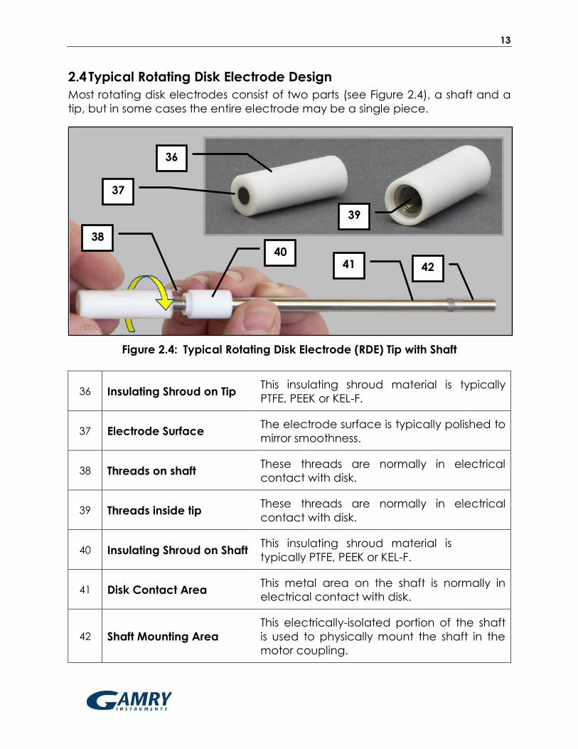
2.4 Typical Rotating Disk Electrode Design
Most rotating disk electrodes consist of two parts (see Figure 2.4), a shaft and a
tip, but in some cases the entire electrode may be a single piece.
Figure 2.4: Typical Rotating Disk Electrode (RDE) Tip with Shaft
36 Insulating Shroud on Tip This insulating shroud material is typically
PTFE, PEEK or KEL-F.
37 Electrode Surface The electrode surface is typically polished to
mirror smoothness.
38 Threads on shaft These threads are normally in electrical
contact with disk.
39 Threads inside tip These threads are normally in electrical
contact with disk.
40 Insulating Shroud on Shaft This insulating shroud material is
typically PTFE, PEEK or KEL-F.
41 Disk Contact Area This metal area on the shaft is normally in
electrical contact with disk.
42 Shaft Mounting Area
This electrically-isolated portion of the shaft
is used to physically mount the shaft in the
motor coupling.
40
38
42 41
39
36
37
14
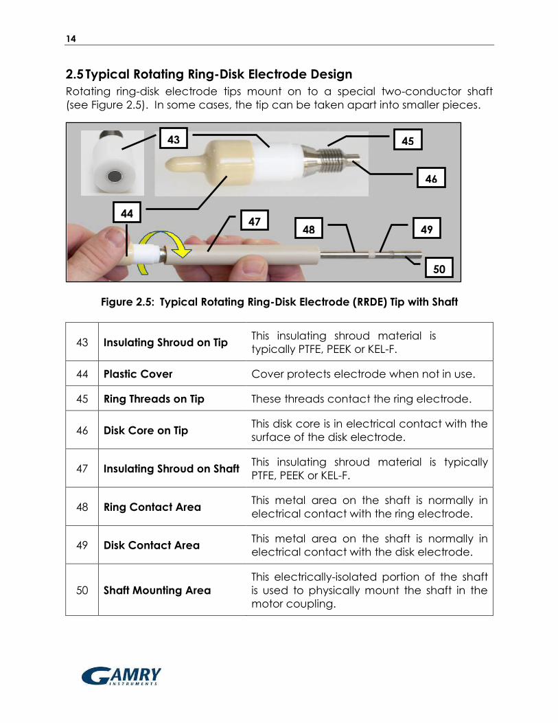
2.5 Typical Rotating Ring-Disk Electrode Design
Rotating ring-disk electrode tips mount on to a special two-conductor shaft
(see Figure 2.5). In some cases, the tip can be taken apart into smaller pieces.
Figure 2.5: Typical Rotating Ring-Disk Electrode (RRDE) Tip with Shaft
43 Insulating Shroud on Tip This insulating shroud material is
typically PTFE, PEEK or KEL-F.
44 Plastic Cover Cover protects electrode when not in use.
45 Ring Threads on Tip These threads contact the ring electrode.
46 Disk Core on Tip This disk core is in electrical contact with the
surface of the disk electrode.
47 Insulating Shroud on Shaft This insulating shroud material is typically
PTFE, PEEK or KEL-F.
48 Ring Contact Area This metal area on the shaft is normally in
electrical contact with the ring electrode.
49 Disk Contact Area This metal area on the shaft is normally in
electrical contact with the disk electrode.
50 Shaft Mounting Area
This electrically-isolated portion of the shaft
is used to physically mount the shaft in the
motor coupling.
43
44
45
47
50
46
49 48

15
3 Installation
3.1 Site Preparation
The rotator system should be located on a sturdy table or laboratory bench with
ample clearance around the perimeter of the rotator enclosure. The front of the
rotator should be unobstructed, and there should be at least 20 centimeters
clearance on each side and behind the rotator, for a total table space of 40 cm
x 60 cm. The location should also include enough space for the control unit (30
cm x 30 cm) and vertical clearance to easily raise and lower the motor unit.
3.2 Unpacking and Setting Up the Rotator
Note:
The numbers appearing in parentheses in the installation
instructions below correspond to the labels in Figure 2.1.
Inspect the contents of the shipping carton.
Remove the top piece of cardboard to
reveal the two smaller boxes in the carton.
The control unit (10) is packed inside the
larger box, and the smaller box holds
additional components. Remove both
boxes and set aside. Then, carefully remove
the enclosure window (7) and the enclosure
base (4) from the box. The center post (1) is
pre-installed in the enclosure base.
Open the smaller box. It should contain the
motor unit (2), the support collar (5), the cell
platform (3), the side post (6), two banana
cables (9), a small bag of hardware, and a
standard three-pronged laboratory clamp
(with right-angle mount).
Note:
The outer diameter of the side post (6) shown in these photos is
5/8" (15.9 mm), but in some alternate rotator configurations this
diameter may be 1/2" (12.7 mm).
16
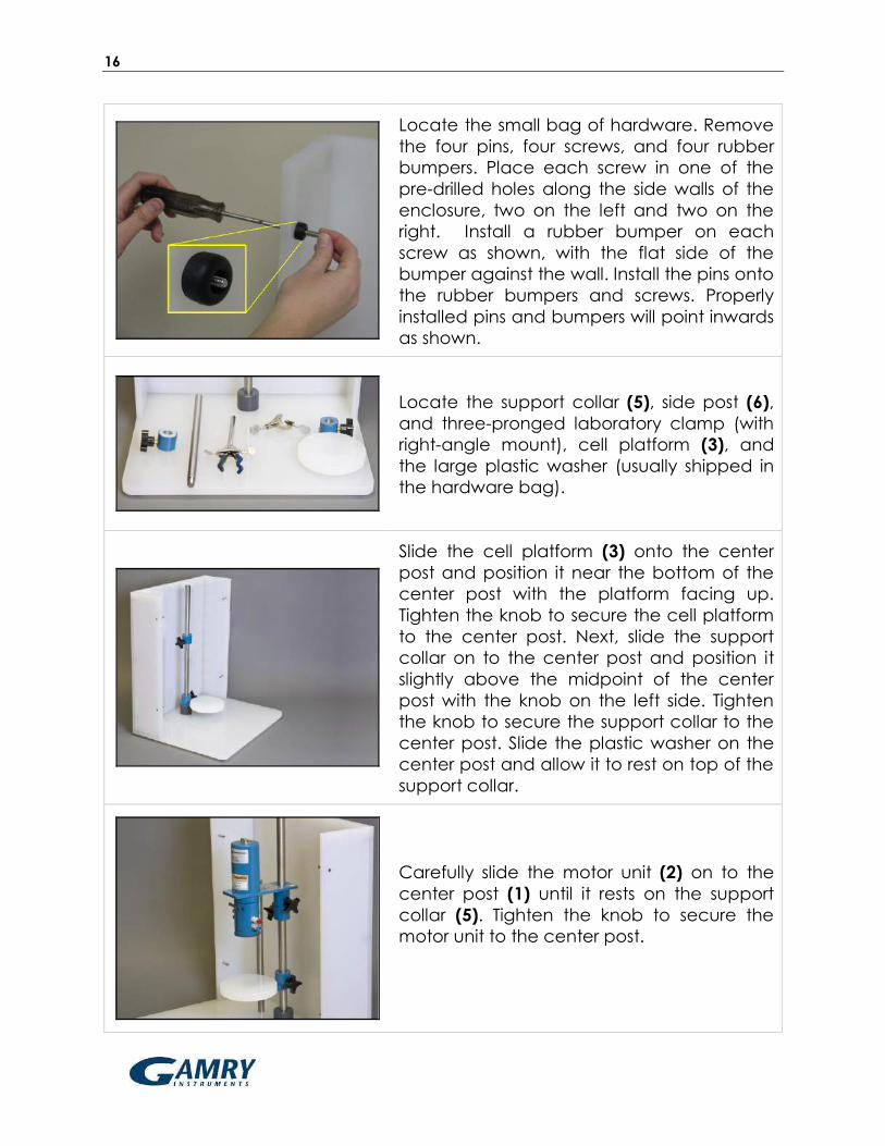
Locate the small bag of hardware. Remove
the four pins, four screws, and four rubber
bumpers. Place each screw in one of the
pre-drilled holes along the side walls of the
enclosure, two on the left and two on the
right. Install a rubber bumper on each
screw as shown, with the flat side of the
bumper against the wall. Install the pins onto
the rubber bumpers and screws. Properly
installed pins and bumpers will point inwards
as shown.
Locate the support collar (5), side post (6),
and three-pronged laboratory clamp (with
right-angle mount), cell platform (3), and
the large plastic washer (usually shipped in
the hardware bag).
Slide the cell platform (3) onto the center
post and position it near the bottom of the
center post with the platform facing up.
Tighten the knob to secure the cell platform
to the center post. Next, slide the support
collar on to the center post and position it
slightly above the midpoint of the center
post with the knob on the left side. Tighten
the knob to secure the support collar to the
center post. Slide the plastic washer on the
center post and allow it to rest on top of the
support collar.
Carefully slide the motor unit (2) on to the
center post (1) until it rests on the support
collar (5). Tighten the knob to secure the
motor unit to the center post.

17
Note:
The relative vertical positions of the cell platform, support
collar, and motor unit may be adjusted as needed to fit the
specific size and shape of a particular electrochemical cell.
There are several holes in the floor of the
enclosure base (4), which are threaded to
accept the side post. Choose one of these
holes and install the side post in it. Then,
mount the laboratory clamp on to the side
post.
There are two short banana cables
(yellow and green) which serve as jumpers
between the left and right brush
connections. Use the yellow cable to
connect the upper (yellow) pair of brush
connections, and use the green cable to
connect the lower (green) pair of brush
connections, running the wires behind the
assembly as shown.
Insert one banana plug stud into the
yellow banana cable, and insert the other
banana plug stud into the green banana
cable. These flat studs are an ideal place
to make connections using alligator clips.
The yellow jacks make electrical contact
with a rotating disk electrode (RDE) or a
rotating cylinder electrode (RCE) tip.
When using a rotating ring-disk electrode
(RRDE), the yellow jacks make contact
with the disk, and the green jacks make
contact with the ring.
18
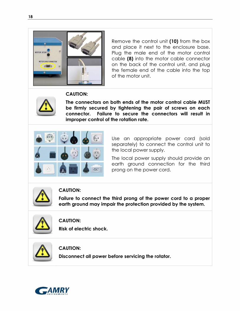
Remove the control unit (10) from the box
and place it next to the enclosure base.
Plug the male end of the motor control
cable (8) into the motor cable connector
on the back of the control unit, and plug
the female end of the cable into the top
of the motor unit.
CAUTION:
The connectors on both ends of the motor control cable MUST
be firmly secured by tightening the pair of screws on each
connector. Failure to secure the connectors will result in
improper control of the rotation rate.
Use an appropriate power cord (sold
separately) to connect the control unit to
the local power supply.
The local power supply should provide an
earth ground connection for the third
prong on the power cord.
CAUTION:
Failure to connect the third prong of the power cord to a proper
earth ground may impair the protection provided by the system.
CAUTION:
Risk of electric shock.
CAUTION:
Disconnect all power before servicing the rotator.

19
Attach the enclosure window by hooking it
on to the four pins. The window will rest
securely on the enclosure base.
CAUTION:
Do not rotate the electrode unless the enclosure window is
securely mounted to the four pins.

20

21
4 Operation
This section of the manual discusses information pertaining to routine operation
of the rotator. Users of the rotator should be familiar with all of the information in
this section prior to operating the rotator.
4.1 The Rotating Shaft
The electrode shaft normally rotates in a clockwise direction as viewed from the
top of the rotator. The upper end of a standard shaft has a 1/4" (6.35 mm) outer
diameter. When properly mounted in the rotator, the upper 2.5” (63.5 mm) of
the shaft is inside the motor unit, while the remaining length of the shaft extends
down below the motor unit.
The rotator accepts shafts for use with Rotating Disk Electrodes (RDEs), Rotating
Cylinder Electrodes (RCE) or Rotating Ring-Disk Electrodes (RRDEs). Electrical
connection is accomplished using one or more silver-carbon brushes to contact
metal surfaces on the upper portion of the rotating shaft. Each shaft is specially
designed to provide one or two current paths down to the electrode tip which
are electrically isolated from the mounting area near the top of the shaft.
Figure 4.1: Contact Areas at Top of Rotating Electrode Shafts

22
The uppermost portion of the shaft is used to mount the shaft into the rotator
(see Figure 4.1). This mounting area is electrically isolated from the remainder of
the shaft so that the electrode connections remain isolated from the rotator
chassis. An insulating spacer just below the mounting area isolates the mounting
area from the electrode contact area.
For an RDE or RCE shaft (see Figure 4.1, left), the entire metal exterior of the shaft
below the insulating spacer is in electrical contact with the disk (or cylinder)
electrode. For an RRDE shaft (see Figure 4.1, right), there are two insulating
spacers. The portion of the shaft between the two insulating spacers provides
electrical contact with the disk electrode. The lower portion of the shaft (below
the lower insulating spacer) provides electrical contact with the ring electrode.
Figure 4.2: The Brush Chamber (side view)
The shaft is connected to the rotator motor via a brass motor coupling located
inside the brush chamber (see Figure 4.2). Two clamshell doors surround the
brush chamber. These doors are securely latched during rotator operation and
push two pairs of contact brushes against the rotating shaft. The upper (yellow)
pair of brushes makes contact with the disk (or cylinder) while the lower (green)
pair makes contact with the ring on a rotating ring-disk electrode.

23
4.1.1 Installing a Shaft
DISCONNECT POWER:
Before removing a shaft or installing a new shaft, turn off the
power to the rotator and disconnect the power cord from the
power source.
Tip:
It is often easier to remove or install a shaft disconnecting the
motor control cable and inverting the entire motor unit on the
center post. Several of the photos in this section of the manual
show the rotator motor in such an inverted position.
Loosen the latch on the clamshell doors.
Open the doors to provide access to the
brush chamber.
Tip:
Do not lose the white plastic washer on the door latch.
If there is a shaft already installed, use the
hex driver tool (5/64", provided) to loosen
the two screws on the motor coupling. Do
not remove these screws entirely; just
loosen them by one or two turns of the hex
driver. Usually it is necessary to hold the
motor coupling in place with one hand
while loosening the screws with the other
hand.
Note:
A new rotator has tape around the motor coupling to protect
the hex screws. Remove this tape and loosen the hex screws if
needed to allow the shaft to enter the coupling.

24
Install the shaft by sliding it through the
hole in the lower bearing assembly and
into the brush chamber.
The shaft should be pushed as far as
possible into the motor coupling so that
the contact brushes are properly aligned
with the electrical contact areas on the
rotating electrode shaft (see Figure 4.3).
If the shaft is properly installed, the brushes
will contact metal surfaces on the shaft.
If the shaft is improperly installed, the
brushes may contact an insulating gap on
the shaft, and the connection to the
rotating electrode will fail.
Tip:
Apply a small amount of a silicon-based grease to the top of
the shaft before installing the shaft into the motor coupling. This
helps to prevent the shaft from sticking in the coupling.
Use the hex driver tool (5/64") to securely
tighten both hex screws on the motor
coupling.
Gently tug on the shaft to make sure it is
securely mounted in the motor coupling.
Close the clamshell doors and tighten the latch.
Remount the motor unit on the center post (in the non-inverted position).
CAUTION:
Before reconnecting the rotator power cable or the motor
control cable to the control unit, be sure the control unit power
switch is off and the rotation rate knob is turned to the fully
counterclockwise position.
Reconnect the motor control cable from the control unit to the motor unit.
Reconnect the power cable from the power source to the control unit.

25
Figure 4.3: Proper (left) and Improper (right) Shaft Insertion Positions
CAUTION:
Check the shaft to make sure it is securely mounted in the
rotator. Check the shaft to make sure that it is not bent or
damaged. Do not turn on the rotator if the shaft is loose, bent,
or damaged in any way.
With the rotation rate knob in the fully counterclockwise position, turn on the
control unit.
Slowly turn the rotation rate knob clockwise until the shaft rotates between 100
and 200 RPM.
While the shaft is slowly rotating (100 to 200 RPM), inspect the rotating shaft to
assure that it is rotating properly about the axis of rotation. If the shaft is
wobbling, vibrating, or tilting away from the axis of rotation, then turn off the
rotator and remove the shaft from the rotator.
CAUTION:
If the slowly rotating shaft appears to be wobbling, vibrating, or
tilting away from the axis of rotation, then it is either damaged
or improperly installed. Do not attempt to use a damaged or
improperly installed shaft. Remove the shaft immediately and
replace it with a properly installed and undamaged shaft.
If the shaft is rotating properly along the axis of rotation, then it is ready for use.
Some shafts are actually single-piece electrodes where the electrode tip is
permanently attached to the shaft. But most shafts are designed to accept a
variety of different tips. For these “shaft and tip” designs, the shaft may remain
mounted in the rotator, and changing the tip is a simple matter of unscrewing
one tip and then threading a new tip on to the shaft.

26
Figure 4.4: Installing a Tip on to a Shaft
4.1.2 Changing the Tip on a Shaft
DISCONNECT POWER:
Before removing a tip from a shaft or installing a new tip on to a
shaft, turn off the power to the rotator and disconnect the
power cord from the power source.
When removing a tip from a shaft or installing a new tip on a shaft, use one
hand to prevent the shaft from rotating while using the other hand to gently
turn the tip.
Remove the old tip from the shaft by gently unscrewing the tip by hand.
No tools are required to remove a tip from a shaft.
DO NOT USE TOOLS ON THE SHAFT OR TIP:
Never use a tool to unscrew a tip from a shaft. If a tip cannot
be removed from a shaft by hand, then contact Gamry for
further instructions.
Thread the new tip on to the shaft (see Figure 4.4) and gently tighten it by
hand. Never use a tool to tighten the tip on to the shaft.

27
CAUTION:
Before reconnecting the rotator power cable or the motor
control cable to the control unit, be sure the control unit power
switch is off and the rotation rate knob is turned to the fully
counterclockwise position.
Reconnect the motor control cable from the control unit to the motor unit.
Reconnect the power cable from the power source to the control unit.
CAUTION:
Check the shaft to make sure it is securely mounted in the
rotator. Check the shaft to make sure that it is not bent or
damaged. Do not turn on the rotator if the shaft is loose, bent,
or damaged in any way.
With the rotation rate knob in the fully counterclockwise position, turn on the
control unit.
Slowly turn the rotation rate knob clockwise until the shaft is rotating between
100 and 200 RPM.
While the shaft is slowly rotating (100 to 200 RPM), inspect the rotating shaft
and tip to assure that both are rotating properly about the axis of rotation. If
the shaft or tip is wobbling, vibrating, or tilting away from the axis of rotation,
then turn off the rotator and remove the shaft from the rotator.
CAUTION:
If the slowly rotating shaft and tip appear to be wobbling,
vibrating, or tilting away from the axis of rotation, then the shaft
or the tip or both are improperly installed or damaged. Do not
attempt to use a damaged or improperly installed shaft or tip.
Remove the shaft and tip immediately and replace with a
properly installed and undamaged shaft and tip.
If the shaft and tip are rotating properly along the axis of rotation, then the
next step is to mount the electrochemical cell that holds the test solution
(see Section 4.2).

28
4.2 Mounting the Cell
All cells should be clamped to the side post and also supported from below
using the cell platform. For a cell with multiple side ports, carefully orient the cell
so that any accessories mounted in the side ports have enough clearance.
Smaller cells may be clamped using a traditional laboratory clamp secured to
the center port (see Figure 4.5, left). Larger cells may be clamped using a large
diameter column clamp (see Figure 4.5, right).
Figure 4.5: Properly Supported and Clamped Electrochemical Cells
The cell platform and clamp positions allow adjustment of the vertical position of
the cell with respect to the motor unit. In addition, the vertical position of the
motor unit is easily adjusted. Usually, it is easier to mount and clamp the cell in a
fixed vertical position. Then, the rotating electrode can be moved vertically
down into the cell or up out of the cell as needed.
CAUTION:
When raising and lowering the motor unit, be sure to hold the
motor unit carefully so that it does not unexpectedly fall and
break the glass cell located below the motor unit.
CAUTION:
Position the motor unit with respect to the glass cell so that the
electrode tip is immersed ~1.0 cm into the test solution. Excessive
immersion may corrode the shaft or tip by allowing liquids to seep
into the joint between the shaft and tip.
CAUTION:
Center the rotating electrode within the opening on the cell so
that it does not rub against the walls of the opening. Damage will
occur if the rotating shaft or tip abrades against these walls.

29
4.3 The Enclosure
CAUTION:
Do not rotate the electrode unless the enclosure window is
securely mounted to the four pins (see Figure 4.6 below)
Figure 4.6: Enclosure Properly Mounted on All Four Pins
After the cell has been mounted and the electrode has been lowered into the
cell, securely mount the enclosure by hooking the enclosure to the four pins on
the enclosure base (see Figure 4.6).
Note that the enclosure has small openings near the bottom which permit cell
connections, purge gas tubing, and coolant to be carefully routed to the
electrochemical cell from locations outside the enclosure.
4.4 Cell Connections
The counter electrode and the reference electrode are usually mounted in
appropriate side ports on the electrochemical cell (see Figure 4.7). The counter
electrode is often a simple platinum wire or carbon rod to which an alligator clip
is easily affixed.

30
Figure 4.7: Connection of Counter and Reference Electrodes
Many commercially available reference electrodes have a pin connector which
can accept the pin jack of the white Gamry reference lead.
4.4.1 RDE and RCE Wiring
There are two pairs of brushes which provide electrical contact with the rotating
shaft (see Figure 4.8). The upper pair of brush contacts (yellow) is used to make
electrical contact with a rotating disk electrode (RDE) or a rotating cylinder
electrode (RCE).
To make good contact on opposite sides of the rotating shaft, both of the
yellow brushes (left and right sides) should be used. Use a short banana jumper
cable to connect the opposing brushes together (see Figure 4.8), and then
connect the working electrode cable(s) from the potentiostat to the jumper
cable.
31
Figure 4.8: Brush Connections for a Rotating Disk Electrode (RDE)
or a Rotating Cylinder Electrode (RCE)
Tip:
Gamry potentiostats provide separate cable connections for the
working electrode and for the working sense. The working
connection carries current while the working sense measures the
potential. Both of these lines must be connected to the rotating
electrode brushes.
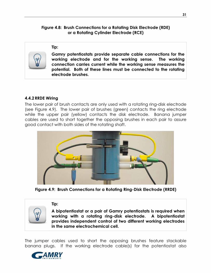
4.4.2 RRDE Wiring
The lower pair of brush contacts are only used with a rotating ring-disk electrode
(see Figure 4.9). The lower pair of brushes (green) contacts the ring electrode
while the upper pair (yellow) contacts the disk electrode. Banana jumper
cables are used to short together the opposing brushes in each pair to assure
good contact with both sides of the rotating shaft.
Figure 4.9: Brush Connections for a Rotating Ring-Disk Electrode (RRDE)
Tip:
A bipotentiostat or a pair of Gamry potentiostats is required when
working with a rotating ring-disk electrode. A bipotentiostat
provides independent control of two different working electrodes
in the same electrochemical cell.
The jumper cables used to short the opposing brushes feature stackable
banana plugs. If the working electrode cable(s) for the potentiostat also
32
terminate with banana plugs, then these plugs can simply be inserted directly
into either end of the jumper cable (see Figure 4.9).
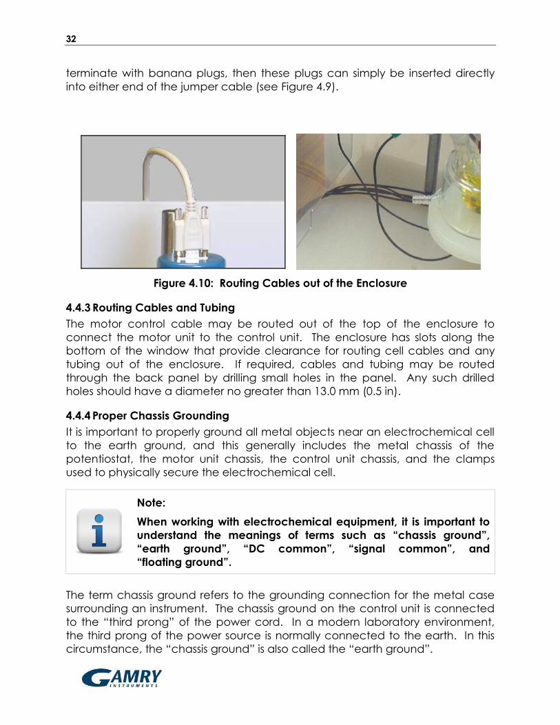
Figure 4.10: Routing Cables out of the Enclosure
4.4.3 Routing Cables and Tubing
The motor control cable may be routed out of the top of the enclosure to
connect the motor unit to the control unit. The enclosure has slots along the
bottom of the window that provide clearance for routing cell cables and any
tubing out of the enclosure. If required, cables and tubing may be routed
through the back panel by drilling small holes in the panel. Any such drilled
holes should have a diameter no greater than 13.0 mm (0.5 in).
4.4.4 Proper Chassis Grounding
It is important to properly ground all metal objects near an electrochemical cell
to the earth ground, and this generally includes the metal chassis of the
potentiostat, the motor unit chassis, the control unit chassis, and the clamps
used to physically secure the electrochemical cell.
Note:
When working with electrochemical equipment, it is important to
understand the meanings of terms such as “chassis ground”,
“earth ground”, “DC common”, “signal common”, and
“floating ground”.
The term chassis ground refers to the grounding connection for the metal case
surrounding an instrument. The chassis ground on the control unit is connected
to the “third prong” of the power cord. In a modern laboratory environment,
the third prong of the power source is normally connected to the earth. In this
circumstance, the “chassis ground” is also called the “earth ground”.

33
While the details of proper grounding for any given potentiostat model may
differ, the general idea is to bring all of the chassis ground connections together
to one particular point to avoid creating “grounding loops”. Many potentiostats
have a convenient connection point for the chassis ground, so this connection
point often serves as a common point to which all of the other chassis ground
lines are connected. In the case of Gamry Reference Family instruments, the
chassis ground is also the floating ground of the instrument. This floating ground
should be connected to the chassis ground of the control box when working
with floating samples and when other instrumentation is not involved. This will
earth ground your floating instrument.
It is also necessary for the metal case around the motor unit to be connected to
the common grounding point. This required connection is usually made in an
indirect fashion. Because the motor control cable (which connects the motor
unit to the control unit) is a shielded cable, the shield assures that the chassis of
the motor unit and the chassis of the control unit are electrically connected.
Thus, as long as the rotator control unit chassis is connected to the common
grounding point on the potentiostat, then the metal case around the motor unit
is (indirectly) connected to the common grounding point.
4.5 Using the Rotator in a Glove Box
The rotator may be placed in a glove
box when working with air or moisture
sensitive compounds. A smaller base
(sold separately) is available for use in
a glove box (see Figure 4.11).
It is important to understand that the
low humidity environment found in
most glove boxes increases the rate of
wear on both the brush contacts and
the internal brushes within the motor
itself.
Figure 4.11: Glove Box Configuration
To mitigate the wear rate of the brush contacts, it is recommended that four
special low-humidity brushes (sold separately) be installed prior to placing the
rotator in the glove box. Contact the factory for more details.

34
CAUTION:
Using the rotator in a dry environment such as a low humidity
glove box will increase the wear rate of the internal motor
brushes. See section 6.5 for more information about how to
replace a worn motor.

35
4.6 Rotation Rate Control
CAUTION:
Always turn the rotation rate control knob completely
counterclockwise before turning on the rotator.
Note:
The fully counterclockwise position corresponds (nominally) to a
rotation rate of zero. Even with the knob in this position, there may
be some residual rotation (typically less than 10 RPM) in either the
clockwise or counter-clockwise direction.
Always begin each session using the rotator with the power turned off and the
rotation rate control knob in the fully counterclockwise position. The fully
counterclockwise position corresponds to the slowest rotation rate, and it is
always safest to turn on the rotator with the knob in this position.
4.6.1 Manual Control of Rotation
To rotate the electrode under manual control, turn on the control unit power
and slowly turn the rotation rate control knob clockwise. As the knob is turned
clockwise, the rotation rate increases and the display on the control unit shows
the rotation rate.
4.6.2 Monitoring the Rotation Rate
The rotation rate is always displayed on the front panel, but it can also be
monitored at the output jacks on the front panel of the control unit. The signal
presented at the output jacks is a voltage which is proportional to the rotation
rate. The proportionality ratio is 1.0 mV/RPM.
Note:
The rotation rate is controlled to within 1.0% of the display value
selected using the rotation rate control knob. It is normal for the
last one or two digits on the display to flicker.
4.6.3 External Control of the Rotation Rate
It is often convenient for the rotation rate to be controlled via an externally
supplied signal. Most Gamry potentiostats are capable of providing such a
signal to control the rotation rate while simultaneously performing
electrochemical measurements. An externally supplied signal is also required

36
when performing hydrodynamically modulated voltammetry, where the rotation
rate is varied sinusoidally as electrochemical measurements are made with the
potentiostat.
The signal from the potentiostat is a voltage applied to the input jacks on the
front panel of the control unit. This voltage is proportional to the desired rotation
rate. The proportionality ratio is 2.0 RPM/mV, which is the ratio compatible with
Gamry potentiostats. Other ratios are available for use with other potentiostat
models (see Section 6.7).
External control of the rotation rate may involve a signal connection between a
potentiostat from one manufacturer being connected to a rotator from another
manufacturer. The signals on these various instruments may have been
calibrated to different tolerances by each manufacturer. Small signal level
differences within these tolerances can add up, causing the actual rotation rate
(as displayed on the control unit) to differ slightly from the rotation rate (as
specified using the potentiostat software).
CAUTION:
If an external voltage signal is used to control the rotation rate, the
voltage applied to the input jacks should not exceed ±10 VDC.
Note:
The input impedance across the input jacks is 50KΩ.
Tip:
The rotation rate set point is based upon the sum of external
voltage signal and the rotation rate control knob setting. It is
sometimes useful to use the knob setting to establish a baseline
rotation rate while using the external signal to superimpose a
smaller magnitude sine wave.
4.6.4 External Motor Stop Control
An external digital signal can be applied to a pair of banana jacks on the back
panel to bring the rotator to a complete stop. This digital signal can be used by
a potentiostat or other external instrument to assure that the rotation rate is
actually zero.

37
The motor stop signal logic is “active high” by default, meaning that application
of a signal greater than 2.0 volts stops rotating the electrode. If desired, the
rotator can be reconfigured for “active low” logic (see Section 6.8), in which
case, a signal less than 0.8 volts brings the rotator to a stop.
4.7 Circuit Protection
The power switch on the back panel also acts as a circuit breaker to help
protect the control unit circuitry. If the circuit breaker trips, then it can be reset
by turning the power switch to the full “off” position and then turning the switch
back “on” again.
A secondary circuit breaker on the front panel protects the windings in the
motor. If this circuit breaker trips, then it can be reset by pressing the “reset”
button on the front panel.

38

39
5 Electrodes
5.1 Electrode Handling Precautions
Rotating electrode tips and shafts are precision research tools machined to tight
specifications for proper balance when spinning at high rotation rates. When
not in use, an electrode tip should be cleaned, dried, and stored in its original
case. When working with electrode shafts and tips, special care should be
taken not to drop the shaft or tip as this will likely throw the shaft or tip off
balance.
CAUTION:
Do not use a shaft or electrode tip if it has been dropped, bent, or
otherwise physically damaged.
CAUTION:
Any rotating shaft or tip which wobbles, vibrates, or tilts away from
the axis of rotation is either improperly installed or damaged. Do
not attempt to use a damaged or improperly installed shaft or tip.
CAUTION:
Each rotating electrode has a maximum rotation rate limitation.
Do not exceed the maximum rotation rate.
CAUTION:
Do not apply excessive twisting force to the shroud of an
electrode tip when threading it on to the shaft, as this may cause
a leak between the shroud and the electrode.
CAUTION:
Position the motor unit with respect to the glass cell so that the
electrode tip is immersed ~1.0 cm into the test solution. Excessive
immersion may corrode the shaft or tip by allowing liquids to seep
into the joint between the shaft and tip.
CAUTION:
Center the rotating electrode within the opening on the cell so
that it does not rub against the walls of the opening. Damage will
occur if the rotating shaft or tip abrades against these walls.

40
TEMPERATURE LIMITATIONS:
Electrode tips with PTFE shrouds are designed for use at room
temperature (15ºC to 30ºC). Exposing these tips to colder or
warmer temperatures is likely to compromise the seal between
the PTFE shroud and the electrode surface.
Electrode tips with PEEK or KEL-F shrouds are available and are
better suited for use at elevated temperatures.
Note:
After each use of rotating electrode (or electrode tip), clean and
dry the electrode and then return it to the plastic storage box in
which it was originally shipped.
Note:
A polishing kit is available for use in restoring the electrode
surface to its original mirror smooth finish. A slurry of microscopic
abrasive particles may be used to routinely repolish the electrode
surface (usually at the end of each day). In the event of very
serious damage to the electrode surface, it is generally better to
return the electrode to the factory for professional repolishing.
41
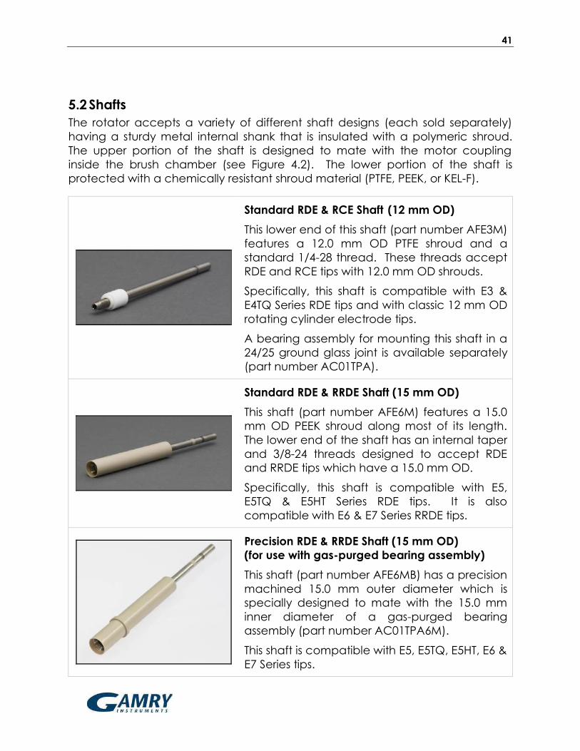
5.2 Shafts
The rotator accepts a variety of different shaft designs (each sold separately)
having a sturdy metal internal shank that is insulated with a polymeric shroud.
The upper portion of the shaft is designed to mate with the motor coupling
inside the brush chamber (see Figure 4.2). The lower portion of the shaft is
protected with a chemically resistant shroud material (PTFE, PEEK, or KEL-F).
Standard RDE & RCE Shaft (12 mm OD)
This lower end of this shaft (part number AFE3M)
features a 12.0 mm OD PTFE shroud and a
standard 1/4-28 thread. These threads accept
RDE and RCE tips with 12.0 mm OD shrouds.
Specifically, this shaft is compatible with E3 &
E4TQ Series RDE tips and with classic 12 mm OD
rotating cylinder electrode tips.
A bearing assembly for mounting this shaft in a
24/25 ground glass joint is available separately
(part number AC01TPA).
Standard RDE & RRDE Shaft (15 mm OD)
This shaft (part number AFE6M) features a 15.0
mm OD PEEK shroud along most of its length.
The lower end of the shaft has an internal taper
and 3/8-24 threads designed to accept RDE
and RRDE tips which have a 15.0 mm OD.
Specifically, this shaft is compatible with E5,
E5TQ & E5HT Series RDE tips. It is also
compatible with E6 & E7 Series RRDE tips.
Precision RDE & RRDE Shaft (15 mm OD)
(for use with gas-purged bearing assembly)
This shaft (part number AFE6MB) has a precision
machined 15.0 mm outer diameter which is
specially designed to mate with the 15.0 mm
inner diameter of a gas-purged bearing
assembly (part number AC01TPA6M).
This shaft is compatible with E5, E5TQ, E5HT, E6 &
E7 Series tips.

42
Precision RCE Shaft (15 mm OD)
(for use with gas-purged bearing assembly)
This shaft (part number AFE9MBA) has a
precision machined 15.0 mm outer diameter
which is specially designed to mate with the
15.0 mm inner diameter of a gas-purged
bearing assembly (part number AC01TPA6M).
This shaft has a PEEK shroud and accepts
cylinder inserts which are 15.0 mm OD x 6.3 mm
tall. The cylinder inserts are sealed between a
pair of rubber washers.
Precision Gas-Purged Bearing Assembly
(15 mm ID)
This gas-purged bearing assembly (part
number AC01TPA6M) fits into the 24/25 center
port on an electrochemical cell. A small plastic
hose barb on the side of the assembly allows
the space within the bearing assembly to be
purged with an inert gas.
The main body of the assembly is made from
chemically resistant PEEK polymer, and the
bearing is ceramic.
Although the bearing is not perfectly sealed,
the inner diameter of the bearing (15 mm ID)
allows a precision machined shaft (15 mm OD)
to pass through the bearing assembly with a
reasonably tight fit.
Simple Taper Plug Assembly
(12 mm ID)
This bearing assembly (part number AC01TPA)
fits into the 24/25 center port on an
electrochemical cell. The main body of the
assembly is made from PTFE, and the bearing
is stainless steel. This assembly is compatible
with the AFE3M shaft and E2 Series single-piece
RDEs. This bearing assembly does not perfectly
seal the electrochemical cell.

43
5.3 RDE Tips
The rotator is compatible with a variety of RDE tips (sold separately), and each
tip design is compatible with one or more shafts as described below.
E3 Series RDE Tips
These RDE tips feature a 12 mm OD PTFE
shroud around a 5 mm OD disk electrode.
These tips fit the standard RDE shaft and may
be used at rotation rates up to 2500 RPM.
Standard disk materials include gold, platinum,
and glassy carbon. Other disk and shroud
materials are available upon request.
Part Numbers
Standard RDE Shaft (for 12 mm OD RDE tips) ................................................................................ AFE3M
Glassy Carbon RDE tip (5 mm OD disk, 12 mm OD shroud) ............................................ AFE3T050GC
Basal Plane Pyrolytic Graphite RDE tip (5 mm OD disk, 12 mm OD shroud) .................. AFE3T050GB
Edge Plane Pyrolytic Graphite RDE tip (5 mm OD disk, 12 mm OD shroud) .................. AFE3T050GE
Aluminum RDE tip (5 mm OD disk, 12 mm OD shroud) ....................................................... AFE3T050AL
Copper RDE tip (5 mm OD disk, 12 mm OD shroud) .......................................................... AFE3T050CU
Gold RDE tip (5 mm OD disk, 12 mm OD shroud) ............................................................... AFE3T050AU
Nickel RDE tip (5 mm OD disk, 12 mm OD shroud) ............................................................... AFE3T050NI
Palladium RDE tip (5 mm OD disk, 12 mm OD shroud) ...................................................... AFE3T050PD
Platinum RDE tip (5 mm OD disk, 12 mm OD shroud) .......................................................... AFE3T050PT
Silver RDE tip (5 mm OD disk, 12 mm OD shroud) .............................................................. AFE3T050AG
Tantalum RDE tip (5 mm OD disk, 12 mm OD shroud) ........................................................ AFE3T050TA
Titanium RDE tip (5 mm OD disk, 12 mm OD shroud) ............................................................ AFE3T050TI
Tungsten RDE tip (5 mm OD disk, 12 mm OD shroud) .......................................................... AFE3T050W
Zinc RDE tip (5 mm OD disk, 12 mm OD shroud) .................................................................. AFE3T050ZN
MAXIMUM ROTATION RATE: 2500 RPM
Do not rotate at rates higher than the maximum rotation rate.
OPERATING TEMPERATURE RANGE: 15ºC to 30ºC
Do not use this electrode outside the operating temperature range.

44
E4TQ Series ChangeDisk RDE Tips
These RDE tips feature a 12 mm OD PTFE
holder which can accept a removable disk
insert. These tips fit the standard RDE shaft and
may be used at rotation rates up to 2000 RPM.
The disk insert (5 mm OD x 4 mm thick) is
typically fabricated from fabricated from gold,
platinum, or glassy carbon. Other disk materials
are available upon request.
Part Numbers
Standard RDE Shaft (for 12 mm OD RDE tips) ................................................................................ AFE3M
ChangeDisk RDE tip (12 mm OD shroud, accepts 5 mm OD x 4 mm thick disks) .......... AFE4TQ050
Toolkit (for removing and polishing disk inserts) ........................................................................ AFE4K050
Glassy Carbon Disk Insert (5 mm OD x 4 mm thick) ................................................... AFED050P040GC
Basal Plane Pyrolytic Graphite Disk Insert (5 mm OD x 4 mm thick) ........................ AFED050P040GB
Edge Plane Pyrolytic Graphite Disk Insert (5 mm OD x 4 mm thick) ........................ AFED050P040GE
Aluminum Disk Insert (5 mm OD x 4 mm thick) ............................................................. AFED050P040AL
Copper Disk Insert (5 mm OD x 4 mm thick) ................................................................ AFED050P040CU
Gold Disk Insert (5 mm OD x 4 mm thick) ..................................................................... AFED050P040AU
Nickel Disk Insert (5 mm OD x 4 mm thick) ..................................................................... AFED050P040NI
Palladium Disk Insert (5 mm OD x 4 mm thick) ............................................................. AFED050P040PD
Platinum Disk Insert (5 mm OD x 4 mm thick) ................................................................. AFED050P040PT
Silver Disk Insert (5 mm OD x 4 mm thick) ..................................................................... AFED050P040AG
Tantalum Disk Insert (5 mm OD x 4 mm thick) .............................................................. AFED050P040TA
Titanium Disk Insert (5 mm OD x 4 mm thick) .................................................................. AFED050P040TI
Tungsten Disk Insert (5 mm OD x 4 mm thick) ................................................................ AFED050P040W
Zinc Disk Insert (5 mm OD x 4 mm thick) ........................................................................ AFED050P040ZN
MAXIMUM ROTATION RATE: 2000 RPM
Do not rotate at rates higher than the maximum rotation rate.
OPERATING TEMPERATURE RANGE: 15ºC to 30ºC
Do not use this electrode outside the operating temperature range.
45
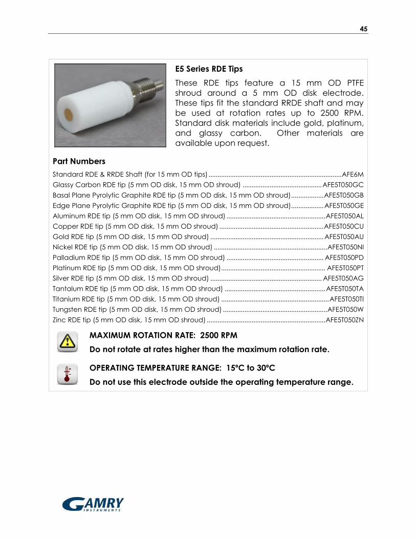
E5 Series RDE Tips
These RDE tips feature a 15 mm OD PTFE
shroud around a 5 mm OD disk electrode.
These tips fit the standard RRDE shaft and may
be used at rotation rates up to 2500 RPM.
Standard disk materials include gold, platinum,
and glassy carbon. Other materials are
available upon request.
Part Numbers
Standard RDE & RRDE Shaft (for 15 mm OD tips) .......................................................................... AFE6M
Glassy Carbon RDE tip (5 mm OD disk, 15 mm OD shroud) ............................................ AFE5T050GC
Basal Plane Pyrolytic Graphite RDE tip (5 mm OD disk, 15 mm OD shroud) .................. AFE5T050GB
Edge Plane Pyrolytic Graphite RDE tip (5 mm OD disk, 15 mm OD shroud) .................. AFE5T050GE
Aluminum RDE tip (5 mm OD disk, 15 mm OD shroud) ....................................................... AFE5T050AL
Copper RDE tip (5 mm OD disk, 15 mm OD shroud) .......................................................... AFE5T050CU
Gold RDE tip (5 mm OD disk, 15 mm OD shroud) ............................................................... AFE5T050AU
Nickel RDE tip (5 mm OD disk, 15 mm OD shroud) ............................................................... AFE5T050NI
Palladium RDE tip (5 mm OD disk, 15 mm OD shroud) ...................................................... AFE5T050PD
Platinum RDE tip (5 mm OD disk, 15 mm OD shroud) .......................................................... AFE5T050PT
Silver RDE tip (5 mm OD disk, 15 mm OD shroud) .............................................................. AFE5T050AG
Tantalum RDE tip (5 mm OD disk, 15 mm OD shroud) ........................................................ AFE5T050TA
Titanium RDE tip (5 mm OD disk, 15 mm OD shroud) ............................................................ AFE5T050TI
Tungsten RDE tip (5 mm OD disk, 15 mm OD shroud) .......................................................... AFE5T050W
Zinc RDE tip (5 mm OD disk, 15 mm OD shroud) .................................................................. AFE5T050ZN
MAXIMUM ROTATION RATE: 2500 RPM
Do not rotate at rates higher than the maximum rotation rate.
OPERATING TEMPERATURE RANGE: 15ºC to 30ºC
Do not use this electrode outside the operating temperature range.
46
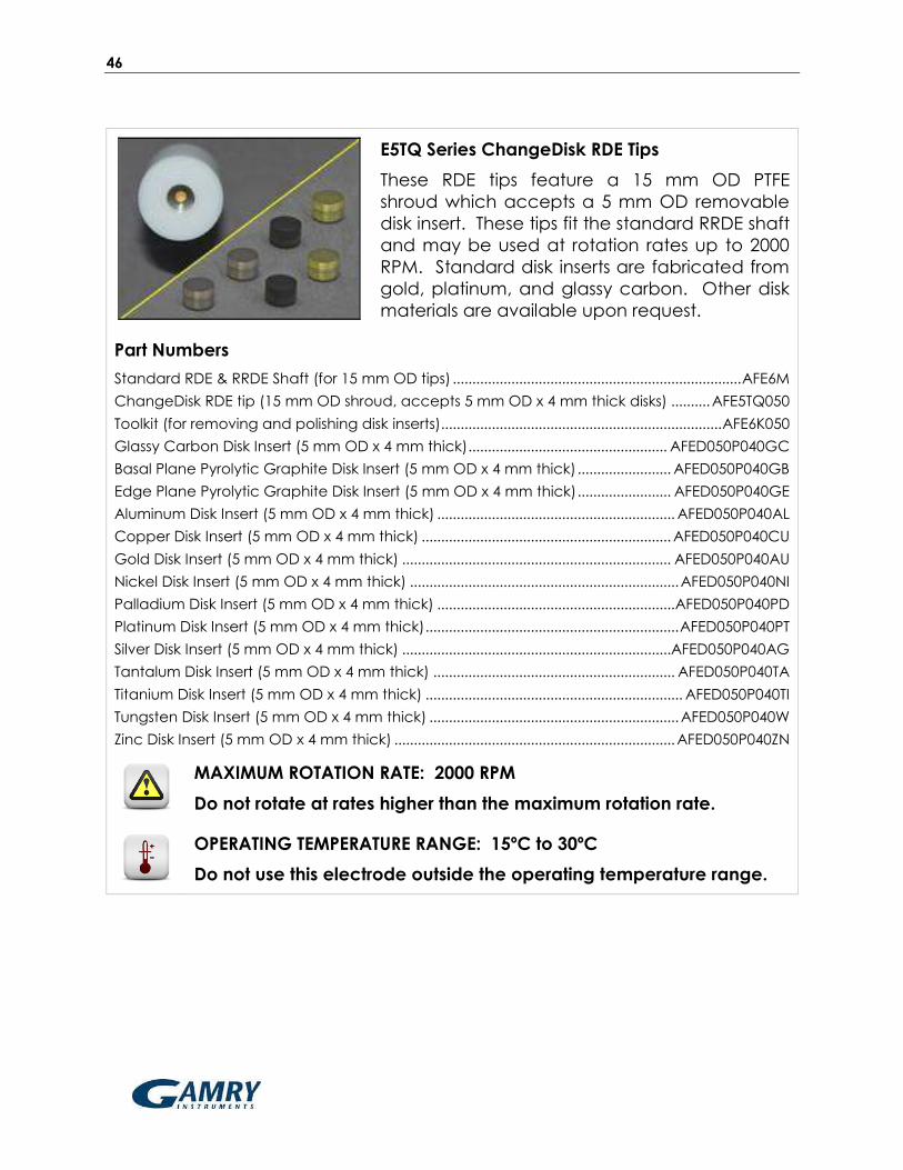
E5TQ Series ChangeDisk RDE Tips
These RDE tips feature a 15 mm OD PTFE
shroud which accepts a 5 mm OD removable
disk insert. These tips fit the standard RRDE shaft
and may be used at rotation rates up to 2000
RPM. Standard disk inserts are fabricated from
gold, platinum, and glassy carbon. Other disk
materials are available upon request.
Part Numbers
Standard RDE & RRDE Shaft (for 15 mm OD tips) .......................................................................... AFE6M
ChangeDisk RDE tip (15 mm OD shroud, accepts 5 mm OD x 4 mm thick disks) .......... AFE5TQ050
Toolkit (for removing and polishing disk inserts) ........................................................................ AFE6K050
Glassy Carbon Disk Insert (5 mm OD x 4 mm thick) ................................................... AFED050P040GC
Basal Plane Pyrolytic Graphite Disk Insert (5 mm OD x 4 mm thick) ........................ AFED050P040GB
Edge Plane Pyrolytic Graphite Disk Insert (5 mm OD x 4 mm thick) ........................ AFED050P040GE
Aluminum Disk Insert (5 mm OD x 4 mm thick) ............................................................. AFED050P040AL
Copper Disk Insert (5 mm OD x 4 mm thick) ................................................................ AFED050P040CU
Gold Disk Insert (5 mm OD x 4 mm thick) ..................................................................... AFED050P040AU
Nickel Disk Insert (5 mm OD x 4 mm thick) ..................................................................... AFED050P040NI
Palladium Disk Insert (5 mm OD x 4 mm thick) ............................................................. AFED050P040PD
Platinum Disk Insert (5 mm OD x 4 mm thick) ................................................................. AFED050P040PT
Silver Disk Insert (5 mm OD x 4 mm thick) ..................................................................... AFED050P040AG
Tantalum Disk Insert (5 mm OD x 4 mm thick) .............................................................. AFED050P040TA
Titanium Disk Insert (5 mm OD x 4 mm thick) .................................................................. AFED050P040TI
Tungsten Disk Insert (5 mm OD x 4 mm thick) ................................................................ AFED050P040W
Zinc Disk Insert (5 mm OD x 4 mm thick) ........................................................................ AFED050P040ZN
MAXIMUM ROTATION RATE: 2000 RPM
Do not rotate at rates higher than the maximum rotation rate.
OPERATING TEMPERATURE RANGE: 15ºC to 30ºC
Do not use this electrode outside the operating temperature range.

47
E5HT Series HotSpot RDE Tips
These RDE tips feature a 15 mm OD PEEK shroud
around a 5 mm OD disk electrode. The PEEK
shroud permits these RDE tips to be used at
temperatures up to 80ºC. These tips fit the
standard RRDE shaft and may be used at
rotation rates up to 2500 RPM. Standard disk
materials include gold, platinum, and glassy
carbon. Other materials are available upon
request.
Part Numbers
Standard RDE & RRDE Shaft (for 15 mm OD tips) .......................................................................... AFE6M
Glassy Carbon HotSpot RDE tip (5 mm OD disk, 15 mm OD shroud, 80ºC limit) ...... AFE5T050GCHT
Aluminum HotSpot RDE tip (5 mm OD disk, 15 mm OD, 80ºC limit) .............................. AFE5T050ALHT
Copper HotSpot RDE tip (5 mm OD disk, 15 mm OD, 80ºC limit) ................................. AFE5T050CUHT
Gold HotSpot RDE tip (5 mm OD disk, 15 mm OD, 80ºC limit) ...................................... AFE5T050AUHT
Nickel HotSpot RDE tip (5 mm OD disk, 15 mm OD, 80ºC limit) ..................................... AFE5T050NIHT
Palladium HotSpot RDE tip (5 mm OD disk, 15 mm OD, 80ºC limit) ............................. AFE5T050PDHT
Platinum HotSpot RDE tip (5 mm OD disk, 15 mm OD, 80ºC limit) ................................ AFE5T050PTHT
Silver HotSpot RDE tip (5 mm OD disk, 15 mm OD, 80ºC limit) ..................................... AFE5T050AGHT
Tantalum HotSpot RDE tip (5 mm OD disk, 15 mm OD, 80ºC limit) ............................... AFE5T050TAHT
Titanium HotSpot RDE tip (5 mm OD disk, 15 mm OD, 80ºC limit) ................................... AFE5T050TIHT
Tungsten HotSpot RDE tip (5 mm OD disk, 15 mm OD, 80ºC limit) .................................AFE5T050WHT
Zinc HotSpot RDE tip (5 mm OD disk, 15 mm OD, 80ºC limit) .........................................AFE5T050ZNHT
MAXIMUM ROTATION RATE: 2500 RPM
Do not rotate at rates higher than the maximum rotation rate.
OPERATING TEMPERATURE RANGE: 15ºC to 80ºC
Do not use this electrode outside the operating temperature range.
CHEMICAL INCOMPATIBILTY:
The shroud material (PEEK) may be discolored by prolonged
exposure to concentrated acids.
Note:
RDE tips with PEEK shrouds are considerably more difficult to polish by
hand than tips with PTFE shrouds. Mechanical polishing is
recommended if the appropriate equipment is available.
48
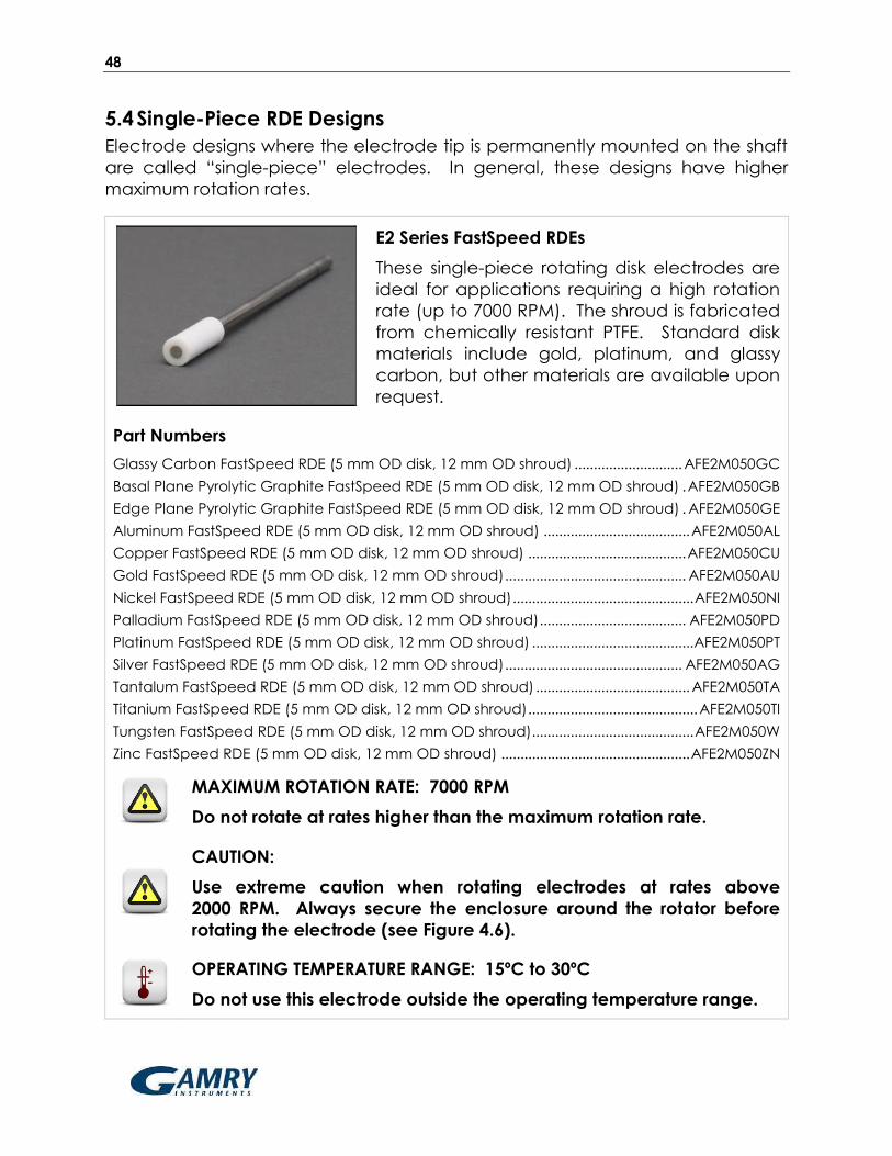
5.4 Single-Piece RDE Designs
Electrode designs where the electrode tip is permanently mounted on the shaft
are called “single-piece” electrodes. In general, these designs have higher
maximum rotation rates.
E2 Series FastSpeed RDEs
These single-piece rotating disk electrodes are
ideal for applications requiring a high rotation
rate (up to 7000 RPM). The shroud is fabricated
from chemically resistant PTFE. Standard disk
materials include gold, platinum, and glassy
carbon, but other materials are available upon
request.
Part Numbers
Glassy Carbon FastSpeed RDE (5 mm OD disk, 12 mm OD shroud) ............................ AFE2M050GC
Basal Plane Pyrolytic Graphite FastSpeed RDE (5 mm OD disk, 12 mm OD shroud) . AFE2M050GB
Edge Plane Pyrolytic Graphite FastSpeed RDE (5 mm OD disk, 12 mm OD shroud) . AFE2M050GE
Aluminum FastSpeed RDE (5 mm OD disk, 12 mm OD shroud) ...................................... AFE2M050AL
Copper FastSpeed RDE (5 mm OD disk, 12 mm OD shroud) ......................................... AFE2M050CU
Gold FastSpeed RDE (5 mm OD disk, 12 mm OD shroud) ............................................... AFE2M050AU
Nickel FastSpeed RDE (5 mm OD disk, 12 mm OD shroud) ............................................... AFE2M050NI
Palladium FastSpeed RDE (5 mm OD disk, 12 mm OD shroud) ...................................... AFE2M050PD
Platinum FastSpeed RDE (5 mm OD disk, 12 mm OD shroud) .......................................... AFE2M050PT
Silver FastSpeed RDE (5 mm OD disk, 12 mm OD shroud) .............................................. AFE2M050AG
Tantalum FastSpeed RDE (5 mm OD disk, 12 mm OD shroud) ........................................ AFE2M050TA
Titanium FastSpeed RDE (5 mm OD disk, 12 mm OD shroud) ............................................ AFE2M050TI
Tungsten FastSpeed RDE (5 mm OD disk, 12 mm OD shroud).......................................... AFE2M050W
Zinc FastSpeed RDE (5 mm OD disk, 12 mm OD shroud) ................................................. AFE2M050ZN
MAXIMUM ROTATION RATE: 7000 RPM
Do not rotate at rates higher than the maximum rotation rate.
CAUTION:
Use extreme caution when rotating electrodes at rates above
2000 RPM. Always secure the enclosure around the rotator before
rotating the electrode (see Figure 4.6).
OPERATING TEMPERATURE RANGE: 15ºC to 30ºC
Do not use this electrode outside the operating temperature range.

49
5.5 RRDE Tips
All RRDE tips have 15 mm OD shrouds made from either PTFE or PEEK. The ring
electrode is permanently mounted in the RRDE tip, but the disk electrode may
be permanently mounted or removable.
E6 Series ChangeDisk RRDE Tips
These ring-disk electrode tips feature a PTFE
shroud and the option to remove and replace
the disk insert. These tips fit the standard RRDE
shaft and may be used at rotation rates up to
2500 RPM. Standard disk and ring materials
include gold, platinum, and glassy carbon.
Other materials are available upon request.
Part Numbers
Standard RDE & RRDE Shaft (for 15 mm OD tips) .......................................................................... AFE6M
Toolkit (for removing and polishing disk inserts) ........................................................................ AFE6K050
ChangeDisk RRDE Tip (platinum ring, accepts 5 mm OD x 4 mm thick disks) .................... AFE6R1PT
ChangeDisk RRDE Tip (gold ring, accepts 5 mm OD x 4 mm thick disks) .......................... AFE6R1AU
ChangeDisk RRDE Tip (glassy carbon ring, accepts 5 mm OD x 4 mm thick disks) ....... AFE6R1GC
Glassy Carbon Disk Insert (5 mm OD x 4 mm thick) ................................................... AFED050P040GC
Basal Plane Pyrolytic Graphite Disk Insert (5 mm OD x 4 mm thick) ........................ AFED050P040GB
Edge Plane Pyrolytic Graphite Disk Insert (5 mm OD x 4 mm thick) ........................ AFED050P040GE
Aluminum Disk Insert (5 mm OD x 4 mm thick) ............................................................. AFED050P040AL
Copper Disk Insert (5 mm OD x 4 mm thick) ................................................................ AFED050P040CU
Gold Disk Insert (5 mm OD x 4 mm thick) ..................................................................... AFED050P040AU
Nickel Disk Insert (5 mm OD x 4 mm thick) ..................................................................... AFED050P040NI
Palladium Disk Insert (5 mm OD x 4 mm thick) ............................................................. AFED050P040PD
Platinum Disk Insert (5 mm OD x 4 mm thick) ................................................................. AFED050P040PT
Silver Disk Insert (5 mm OD x 4 mm thick) ..................................................................... AFED050P040AG
Tantalum Disk Insert (5 mm OD x 4 mm thick) .............................................................. AFED050P040TA
Titanium Disk Insert (5 mm OD x 4 mm thick) .................................................................. AFED050P040TI
Tungsten Disk Insert (5 mm OD x 4 mm thick) ................................................................ AFED050P040W
Zinc Disk Insert (5 mm OD x 4 mm thick) ........................................................................ AFED050P040ZN
MAXIMUM ROTATION RATE: 2500 RPM
Do not rotate at rates higher than the maximum rotation rate.
OPERATING TEMPERATURE RANGE: 15ºC to 30ºC
Do not use this electrode outside the operating temperature range.
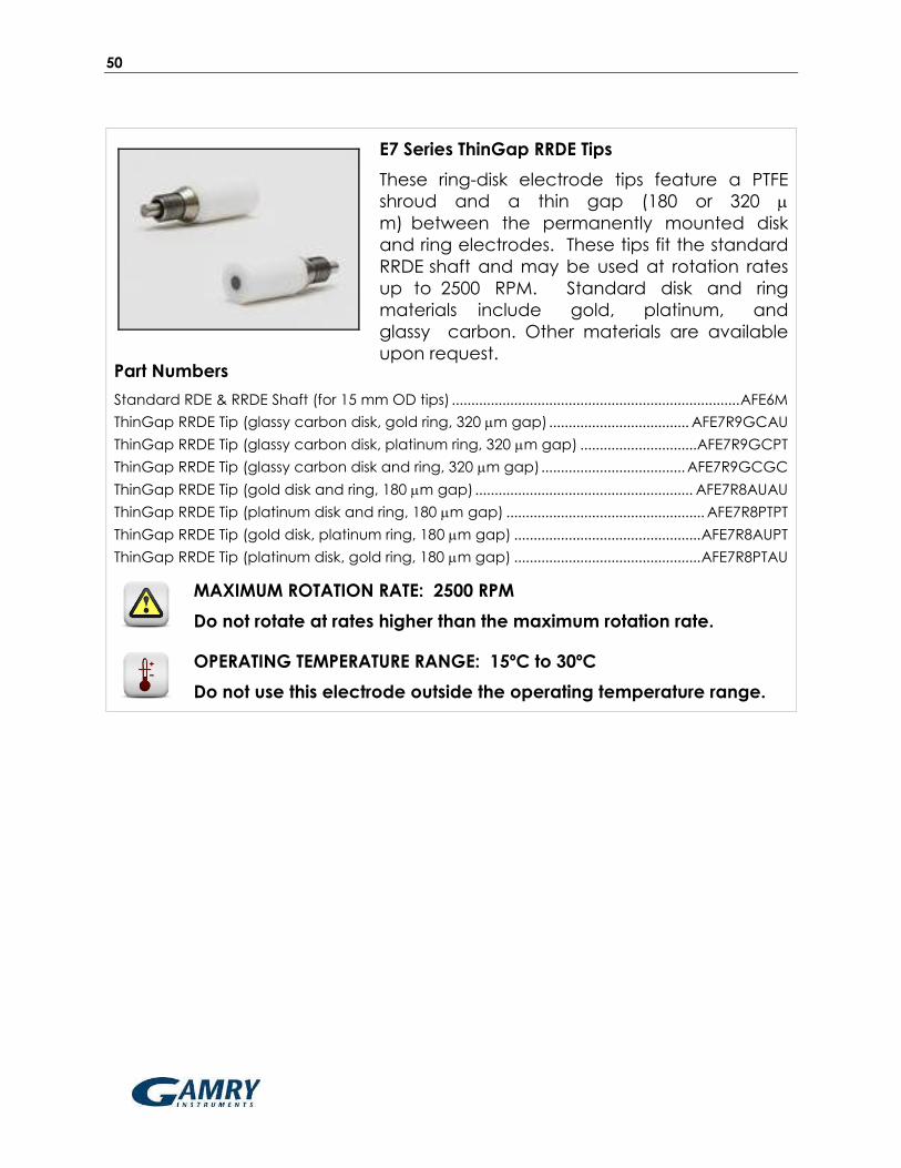
50
E7 Series ThinGap RRDE Tips
These ring-disk electrode tips feature a PTFE
shroud and a thin gap (180 or 320
m) between the permanently mounted disk
and ring electrodes. These tips fit the standard
RRDE shaft and may be used at rotation rates
up to 2500 RPM. Standard disk and ring
materials include gold, platinum, and
glassy carbon. Other materials are available
upon request. Part Numbers
Standard RDE & RRDE Shaft (for 15 mm OD tips) .......................................................................... AFE6M
ThinGap RRDE Tip (glassy carbon disk, gold ring, 320 m gap) .................................... AFE7R9GCAU
ThinGap RRDE Tip (glassy carbon disk, platinum ring, 320 m gap) .............................. AFE7R9GCPT
ThinGap RRDE Tip (glassy carbon disk and ring, 320 m gap) ..................................... AFE7R9GCGC
ThinGap RRDE Tip (gold disk and ring, 180 m gap) ........................................................ AFE7R8AUAU
ThinGap RRDE Tip (platinum disk and ring, 180 m gap) ................................................... AFE7R8PTPT
ThinGap RRDE Tip (gold disk, platinum ring, 180 m gap) ................................................ AFE7R8AUPT
ThinGap RRDE Tip (platinum disk, gold ring, 180 m gap) ................................................ AFE7R8PTAU
MAXIMUM ROTATION RATE: 2500 RPM
Do not rotate at rates higher than the maximum rotation rate.
OPERATING TEMPERATURE RANGE: 15ºC to 30ºC
Do not use this electrode outside the operating temperature range.
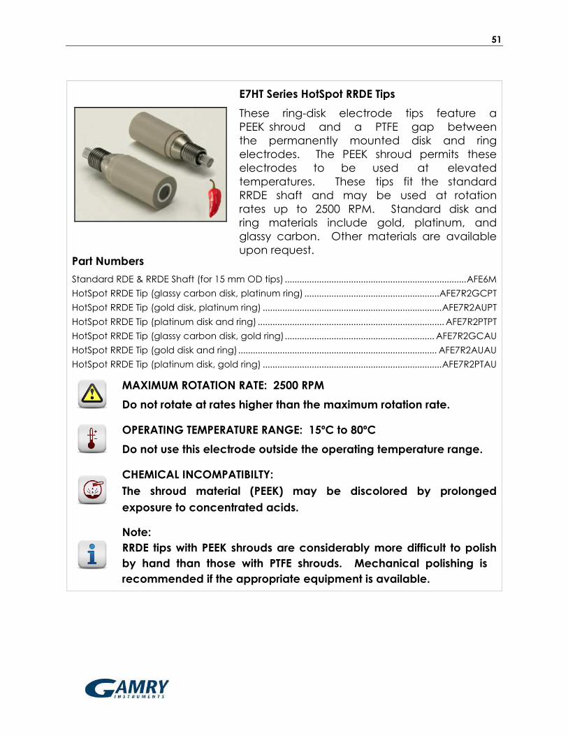
51
E7HT Series HotSpot RRDE Tips
These ring-disk electrode tips feature a
PEEK shroud and a PTFE gap between
the permanently mounted disk and ring
electrodes. The PEEK shroud permits these
electrodes to be used at elevated
temperatures. These tips fit the standard
RRDE shaft and may be used at rotation
rates up to 2500 RPM. Standard disk and
ring materials include gold, platinum, and
glassy carbon. Other materials are available
upon request. Part Numbers
Standard RDE & RRDE Shaft (for 15 mm OD tips) .......................................................................... AFE6M
HotSpot RRDE Tip (glassy carbon disk, platinum ring) ....................................................... AFE7R2GCPT
HotSpot RRDE Tip (gold disk, platinum ring) ......................................................................... AFE7R2AUPT
HotSpot RRDE Tip (platinum disk and ring) ............................................................................ AFE7R2PTPT
HotSpot RRDE Tip (glassy carbon disk, gold ring) ............................................................. AFE7R2GCAU
HotSpot RRDE Tip (gold disk and ring) ................................................................................. AFE7R2AUAU
HotSpot RRDE Tip (platinum disk, gold ring) ......................................................................... AFE7R2PTAU
MAXIMUM ROTATION RATE: 2500 RPM
Do not rotate at rates higher than the maximum rotation rate.
OPERATING TEMPERATURE RANGE: 15ºC to 80ºC
Do not use this electrode outside the operating temperature range.
CHEMICAL INCOMPATIBILTY:
The shroud material (PEEK) may be discolored by prolonged
exposure to concentrated acids.
Note:
RRDE tips with PEEK shrouds are considerably more difficult to polish
by hand than those with PTFE shrouds. Mechanical polishing is
recommended if the appropriate equipment is available.

52
5.6 RCE Tips
Two styles of rotating cylinder electrode tips are available, each with a different
outer diameter (12 or 15 mm OD). The older 12 mm OD design is still supported,
but new RCE users are encouraged to begin working with the newer 15 mm
design. The 15 mm design is generally offered in conjunction with a special one
liter glass cell designed specifically for use with the 15 mm OD RCE system.
15 mm OD RCE System
A typical 15-mm OD RCE system includes a
15 mm OD RCE shaft (part number AFE9MBA),
a one liter corrosion cell (part number
AFCELL8), and a gas-purged bearing assembly
(part number AC01TPA6M). The shaft is able to
accept standard cylinder samples (15 mm OD
x 6.3 mm tall) fabricated from carbon steel or
various stainless steels. Other materials are
available on request.
MAXIMUM ROTATION RATE: 4000 RPM
Do not rotate at rates higher than the maximum rotation rate.
OPERATING TEMPERATURE RANGE: 15ºC to 80ºC
Do not use this electrode outside the operating temperature range.
12 mm OD RCE Tips
Traditional 12 mm OD RCE tips accept cylinder
inserts (12 mm OD x 7.96 mm tall) fabricated
from carbon or stainless steel. Other materials
are available on request. This RCE tip fits on to
the standard RDE/RCE shaft (shaft part number
AFE3M). New RCE users are encouraged to
consider the 15 mm OD RCE system instead.
MAXIMUM ROTATION RATE: 2000 RPM
Do not rotate at rates higher than the maximum rotation rate.
OPERATING TEMPERATURE RANGE: 15ºC to 80ºC
Do not use this electrode outside the operating temperature range.

53
6 Maintenance
6.1 Routine Cleaning
Regular maintenance of the rotator primarily consists of keeping the external
surfaces of the system clean by wiping them with a towel moistened with water
or a mild, non-abrasive cleaner.
After about two weeks of continuous use, open the brush chamber and vacuum
out any dust or debris. If necessary, remove the lower bearing assembly for
better access to the brush chamber (see section 6.3), and use a towel
moistened with water or a mild, non-abrasive cleaner to clean the inner surfaces
of the brush chamber.
The electrode brushes may deposit silver-carbon dust inside the brush chamber
and deposit a film on the surface of the rotating shaft. A thin film on the shaft
actually improves the contact between the brush and the shaft does not need
to be cleaned unless the film is rough or bumpy.
6.2 Brush Replacement
The brushes contact the rotating shaft, slowly wearing during normal use, and
periodically, the brushes must be replaced. A simple brush replacement kit is
available, or in the case of serious damage to the entire brush assembly,
the brush and its PTFE holder can be replaced.
6.2.1 Internal Brush Replacement
DISCONNECT POWER:
Before replacing a brush, turn off the power to the rotator and
disconnect the power cord from the power source.
The standard brush replacement kit
(part number ACAR063RM) contains a
small hex key, a new brush, and a
new set screw (installed in the brush).
A special brush replacement kit (part
number ACAR063LHM) should be
used when the rotator is routinely
operated in low humidity conditions
such as inside a glove box.

54
Remove the entire brush assembly from the rotator by unscrewing it as shown
below. It should be possible to remove the brush assembly by hand.
Use the small hex key to remove the set
screw. Note that the required hex key
(0.035”) is included with the brush
replacement kit.
Note:
The brush is spring-loaded. When you remove the set screw,
the brush will tend to fly out of the brush holder. Use a finger to
hold it in place as you are removing the set screw.
After removing the set screw, remove and
discard the old brush, but do not discard
the empty brush holder.
The new replacement brush includes a set
screw which is already installed.
Temporarily remove this set screw.
Be careful not to misplace the set screw.

55
Carefully slide the new spring-loaded brush
into the brush holder.
Be careful to properly align the set screw
hole with the slot on the side of the brush
holder.
While squeezing the new brush into the
brush holder, use the hex key to reinstall
the set screw.
Tighten the set screw until it stops turning.
Note:
The set screw should protrude slightly into the slot, and the
brush should be free to travel to the extent permitted by the
width of the slot.
Reinstall the brush assembly by threading it back into the side of the rotator.
Hand-tighten the brush assembly. Do not use tools to tighten the assembly.
INTENTIONAL WEAR PERIOD:
After installing a new brush, install a shaft and allow the rotator
to run at 1000 RPM for at least eight (8) hours. This rotation
period wears a concave groove into the new brush. This
intentional wear actually improves the electrical contact
between the brush and the shaft.

56
6.2.2 Complete Brush Assembly Replacement
In the event that the main body of the brush assembly is damaged, it may be
necessary to replace the entire brush assembly.
DISCONNECT POWER:
Before replacing a brush, turn off the power to the rotator and
disconnect the power cord from the power source.
Remove the old brush assembly from the rotator by unscrewing it as shown
below. Remove the old brush assembly by hand. (Use tools only if necessary!)
Install the new brush assembly by threading it by hand into the side of the
rotator. Do not use tools to tighten the brush assembly.
INTENTIONAL WEAR PERIOD:
After installing a new brush, install a shaft and allow the rotator
to run at 1000 RPM for at least eight (8) hours. This rotation
period wears a concave groove into the new brush. This
intentional wear actually improves the electrical contact
between the brush and the shaft.

57
6.3 Lower Bearing Replacement
The lower bearing assembly is a common replacement item due to mechanical
wear and also due to exposure to corrosive vapors from the cell solution. The
standard lower bearing assembly (part number ACMR3301X) contains a stainless
steel bearing which is generally resistant to corrosive attack. In laboratories
where particularly corrosive solutions are used, an assembly based on a ceramic
bearing (part number ACMR3302) can be used instead.
DISCONNECT POWER:
Before replacing the lower bearing assembly, turn off the
power to the rotator and disconnect the power cord from the
power source.
Disconnect the motor control cable from the connector on top of the motor
unit. If there is a shaft presently installed the motor unit, remove the shaft.
Disconnect any signal cables from the brush banana jacks (yellow and green).
Use a flathead screwdriver to loosen the four screws that secure the lower
bearing assembly to the motor unit. As you are loosening the final screw with
one hand, catch the bearing assembly with your other hand.
Note:
After the bearing assembly has been removed, it is a good idea to
clean or vacuum out any debris in the brush chamber.
Align the four screw holes on the new bearing assembly with the four threaded
holes in the motor unit.
Thread the four screws into the holes by hand. Then, tighten the screws with a
flathead screwdriver.

58
6.4 Removing the Motor-Coupling Assembly
On rare occasions (such as when replacing a failed motor), it may be necessary
to remove the motor-coupling assembly from the motor unit.
DISCONNECT POWER:
Before removing the motor-coupling assembly, turn off the
power to the rotator and disconnect the power cord from the
power source.
Disconnect the motor control cable from the top of the motor unit.
If there is a shaft presently installed in the motor unit, remove the shaft.
Disconnect any signal cables from the brush banana jacks (yellow and green).
There are two screws which hold the cowling in place (front and back).
Use a flathead screwdriver to remove these two screws from the cowling.
Carefully begin removing the cowling from the motor unit.
The internal cable assembly will prevent the cowling from being completely
removed.
However, there is a junction in the middle of the internal cable assembly
where two white connectors are joined together.
By disconnecting the cable assembly at this junction, it is possible to remove
the cowling completely.

59
Disconnect the junction by releasing the locking mechanism that holds the
connectors together.
The internal cables are secured to the motor using two plastic cable ties.
In order to remove the motor, the lower cable tie must be cut and removed.
CAUTION:
DO NOT REMOVE the upper cable tie. The upper cable tie
protects the fragile connections to the motor.
Note:
The red (positive) and black (negative) lines are connected to
the tachometer, and the white (positive) and green (negative)
lines are connected to the motor.

60
There are four screws which hold the motor in place.
Using a flathead screwdriver, loosen and remove these four screws.
As the fourth and final screw is being removed, be sure to support the motor
and brush chamber from below to prevent damage from a sudden fall.
Carefully lower the motor out of the support while guiding the fragile motor
and tachometer cables through the support.
Carefully separate the motor from the brush chamber.
Note:
After the motor has been removed, it is a good idea to clean or
vacuum out any debris in the brush chamber.

61
6.5 Installing a New Motor-Coupling Assembly
After removing the old motor-coupling assembly (see above), a new motor-
coupling assembly may be installed.
DISCONNECT POWER:
Before installing the motor-coupling assembly, turn off the
power to the rotator and disconnect the power cord from the
power source.
Disconnect the motor control cable from the top of the motor unit.
Disconnect any signal cables from the brush banana jacks (yellow and green).
Examine the new motor coupling unit. There should be one cable tie securing
the cables to the motor (black) as shown below. Do not remove this cable tie.
Remove any extra cable ties (i.e. around the green part of the motor) so that
the cable can move freely.
Align the threaded holes in the new motor with those in the brush chamber
and push the motor up into the support. Carefully feed the cables through the
hole as shown in the figure below.

62
Secure the motor and chamber to the support using four screws.
Connect the internal cable within the cowling to the motor by joining the two
white connectors together.
Replace the cowling on top of the motor and secure it with two screws.
CAUTION:
After installing a new motor, it is necessary to recalibrate the
rotation rate using an optical tachometer (see Figure 6.1).
Figure 6.1: An Optical Tachometer with a Traceable Calibration Certificate

63
6.6 Rotation Rate Calibration
CAUTION:
This procedure requires working inside the control unit while the
control unit is powered on and operating.
HIGH VOLTAGES ARE PRESENT INSIDE THE CONTROL BOX!
KEEP HANDS AND TOOLS AWAY FROM THE POWER ENTRY
MODULE AND THE TWO POWER SUPPLY MODULES!
This procedure requires several special tools listed below:
Metal Shaft: A simple metal shaft must be mounted in the rotator while
performing certain steps in this calibration procedure. The recommended
shaft is a stainless steel rod (1/4" OD x 5" L; 6.35 mm OD x 100 mm L).
Tachometer: A non-contact, optical tachometer (50 to 10000 RPM) is required
to calibrate the rotation rate (see Figure 6.1). Most optical tachometers
require that a piece of reflector tape be affixed to the rotating shaft. When
using the tachometer, follow the instructions of the tachometer manufacturer
carefully with regard to reflector tape size and position.
Screwdrivers: A small, flathead screwdriver is needed to make adjustments to
the trimmer potentiometers (trimmers) on the circuit board. A medium sized
Phillips screwdriver is required to remove the top panel of the control unit.
Allen Key: A small (5/64") hex key is required to turn the hex screws on the
motor coupling when installing or removing a shaft. This hex key is included
with the purchase of a new rotator but can be reordered (part number
THWA078) or purchased at many retail hardware supply stores.
Known Voltage Source: A known voltage source (1000 mV) is required to
calibrate the rotation rate input signal. This known source can be a power
supply or waveform generator, and the value of the known voltage (1000 mV)
should be verified using a calibrated digital voltmeter.
CAUTION:
Verify that the tachometer has a calibration certificate and that
that the calibration period has not expired.

64
Switch off power to the rotator and disconnect the power cord.
With the power cord disconnected, remove the cover from the control unit.
While the power is switched off, note the positions of the various trimmers
located along the top of the main circuit board. A flathead screwdriver is
required to adjust these trimmers.
While the power is switched off, install a
simple metal shaft into the rotator.
This shaft should be a metal rod with the
appropriate diameter (1/4" or 6.35 mm).
Attach a piece of reflector tape on the
end of the shaft for use as a light beam
target (see Figure 6.2).

65
Figure 6.2: Use of Optical Tachometer with Reflective Target
Turn the rotation rate knob fully counter-clockwise. This is the position which
corresponds to a nearly zero rotation rate.
Reconnect the power cord and carefully switch on the rotator.
Slowly increase the rotation rate to 2800 RPM. Use the rotation rate knob on
the front of the control unit to control the rotation rate, but use the calibrated
tachometer to verify that the rate is actually 2800 RPM.
WAITING PERIOD:
Rotate the shaft at 2800 RPM for one (1) hour before continuing
with the calibration process. This waiting period permits all
electronic and mechanical components of the rotator system
to equilibrate and reach a steady state.
Slowly decrease the rotation rate to 2000 RPM. Use the rotation rate knob on
the front of the control unit to control the rotation rate, but use the calibrated
tachometer to verify that the rate is actually 2000 RPM.
While the shaft is rotating at 2000 RPM, adjust trimmer P6 with a screwdriver
until the rotation rate display on the front panel of the control unit reads
2000 RPM (see Figure 6.2).

66
Slowly decrease the rotation rate to 200 RPM. Use the rotation rate knob on
the front of the control unit to control the rotation rate, but use the calibrated
tachometer to verify that the rate is actually 200 RPM.
While the shaft is rotating at 200 RPM, adjust trimmer P7 with a screwdriver until
the rotation rate display on the front panel of the control unit reads
200 RPM.
Turn the rotation rate knob as far as possible in the counter-clockwise
direction. Adjust trimmer P2 until the reading on the rotation rate display is
approximately -10 RPM. At this point, the shaft should be spinning very slowly in
the reverse direction.
Turn the rotation rate knob slowly until the shaft stops turning in either direction.
At this point, the rotation rate display should read nearly zero.
Connect a known voltage source (such as a power supply or waveform
generator) to the rotation rate input signal jacks on the front panel of the
control unit. The positive lead from the voltage source should be connected
to the gray banana jack (labeled “INPUT”), and the negative lead should be
connected to the black banana jack (signal ground).
Using the known voltage source, apply exactly 1000 mV (one volt) to the
rotation rate input signal. At this point, the rotation rate display should indicate
a rotation rate that is nearly 1000 RPM. Use trimmer P5 to adjust the rotation
rate so that the display indicates exactly 1000 RPM.
Note:
The previous step assumes that the rotation rate input signal is
configured for a ratio of 1 RPM/mV. If another ratio has been
chosen (see Section 6.7), then display should indicate either
2000 or 4000 RPM when a one volt input signal is applied.
Disconnect the known voltage source from the rotator.
Turn the rotation rate knob fully counter-clockwise. This is the position which
corresponds to a nearly zero rotation rate.
Switch off power to the rotator and disconnect the power cord.
Use a small (5/64") hex key to loosen the hex screws in the motor coupling and
remove the shaft from the rotator.
Use the hex key to securely retighten the hex screws into the motor coupling.
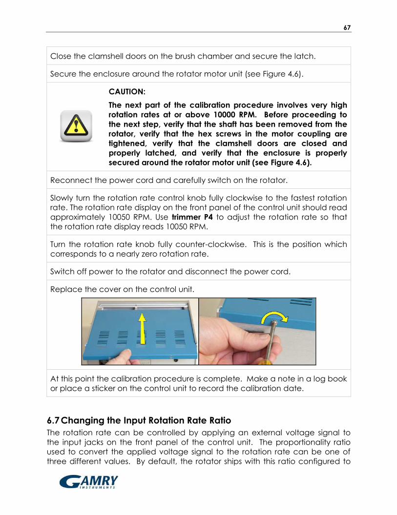
67
Close the clamshell doors on the brush chamber and secure the latch.
Secure the enclosure around the rotator motor unit (see Figure 4.6).
CAUTION:
The next part of the calibration procedure involves very high
rotation rates at or above 10000 RPM. Before proceeding to
the next step, verify that the shaft has been removed from the
rotator, verify that the hex screws in the motor coupling are
tightened, verify that the clamshell doors are closed and
properly latched, and verify that the enclosure is properly
secured around the rotator motor unit (see Figure 4.6).
Reconnect the power cord and carefully switch on the rotator.
Slowly turn the rotation rate control knob fully clockwise to the fastest rotation
rate. The rotation rate display on the front panel of the control unit should read
approximately 10050 RPM. Use trimmer P4 to adjust the rotation rate so that
the rotation rate display reads 10050 RPM.
Turn the rotation rate knob fully counter-clockwise. This is the position which
corresponds to a nearly zero rotation rate.
Switch off power to the rotator and disconnect the power cord.
Replace the cover on the control unit.
At this point the calibration procedure is complete. Make a note in a log book
or place a sticker on the control unit to record the calibration date.
6.7 Changing the Input Rotation Rate Ratio
The rotation rate can be controlled by applying an external voltage signal to
the input jacks on the front panel of the control unit. The proportionality ratio
used to convert the applied voltage signal to the rotation rate can be one of
three different values. By default, the rotator ships with this ratio configured to

68
2.0 RPM/mV (compatible with Gamry potentiostat systems). This ratio can be
changed to 1.0 RPM/mV or to 4.0 RPM/mV (for use with other potentiostats).
DISCONNECT POWER:
Before changing the input ratio, turn off the power to the rotator
and disconnect the power cord from the power source.
With the power cord disconnected, remove the cover from the control unit.
Loosen the screw that secures the main analog board to the front panel, and
then carefully remove the analog board.
On the board, locate the configuration pins with the designation JP2. There is
a small jumper that can be used to short together one of three pairs of pins.
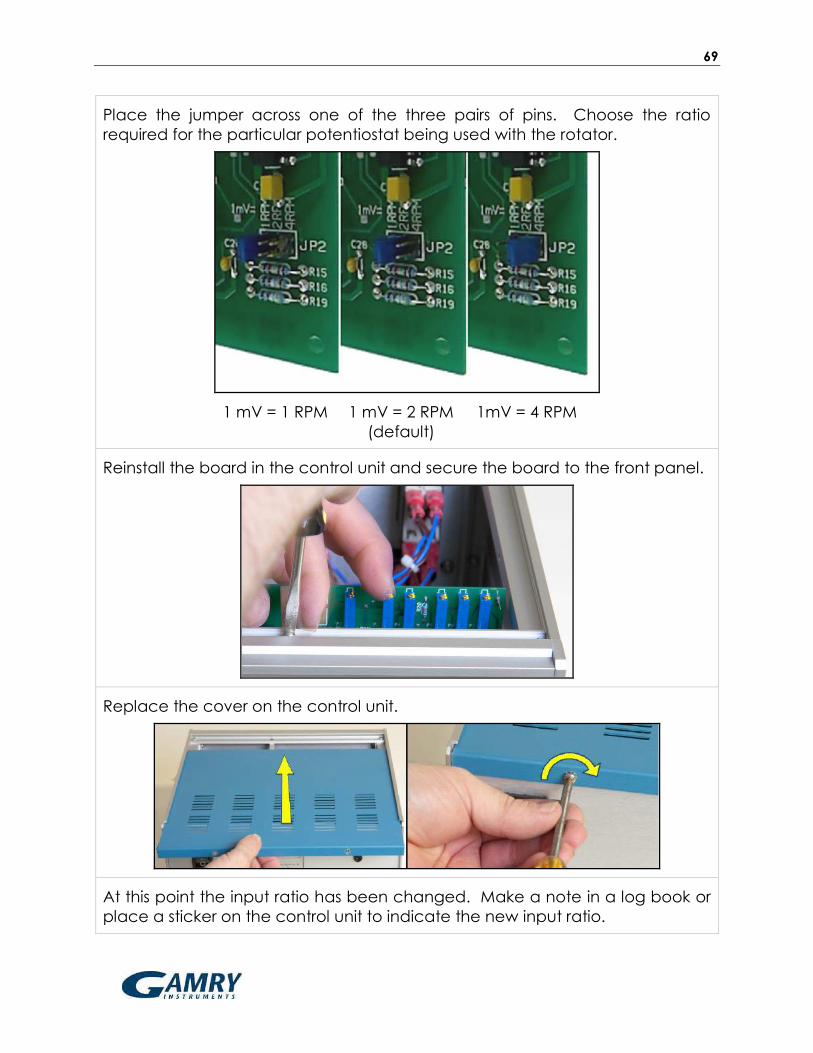
69
Place the jumper across one of the three pairs of pins. Choose the ratio
required for the particular potentiostat being used with the rotator.
1 mV = 1 RPM 1 mV = 2 RPM 1mV = 4 RPM
(default)
Reinstall the board in the control unit and secure the board to the front panel.
Replace the cover on the control unit.
At this point the input ratio has been changed. Make a note in a log book or
place a sticker on the control unit to indicate the new input ratio.

70
6.8 Changing the Motor Stop Signal Logic
The motor stop signal on the back panel of the control unit is a digital signal that
can be used to bring the motor to a complete stop. This digital signal can be
configured for either “active high” or “active low” logic. For the “active high”
case, a digital voltage signal greater than 2.0 volts (presented at the blue
banana jack input on the back panel) will stop the motor. For the “active low”
case, a signal less than 0.8 volts stops the motor.
By default, the rotator ships with “active high” logic (compatible with Gamry
potentiostats), but the rotator can be reconfigured to use “active low” logic if
this is required for use with a third-party potentiostat. Consult the potentiostat
documentation for further details.
DISCONNECT POWER:
Before changing the input ratio, turn off the power to the rotator
and disconnect the power cord from the power source.
With the power cord disconnected, remove the cover from the control unit.
Loosen the screw that secures the main analog board to the front panel, and
then carefully remove the analog board.

71
On the board, locate the configuration pins with the designation JP1. There is
a small jumper that can be placed in one of two positions at this location.
Place the jumper across one of the two positions shown below. Choose the
position required for the particular potentiostat being used with the rotator.
Active LOW Position Active HIGH Position
(default)
Reinstall the board in the control unit and secure the board to the front panel.

72
Replace the cover on the control unit.
At this point the motor stop signal logic has been changed. Make a note in a
log book or place a sticker on the control unit to indicate the new logic.
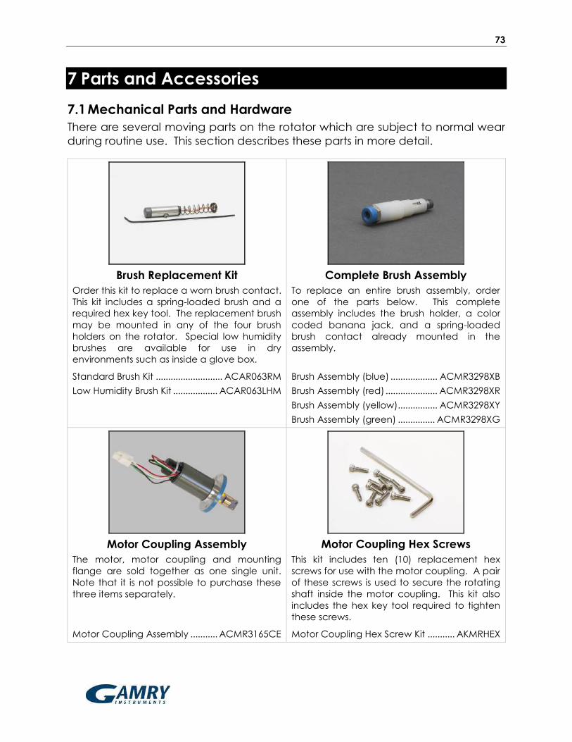
73
7 Parts and Accessories
7.1 Mechanical Parts and Hardware
There are several moving parts on the rotator which are subject to normal wear
during routine use. This section describes these parts in more detail.
Brush Replacement Kit
Order this kit to replace a worn brush contact.
This kit includes a spring-loaded brush and a
required hex key tool. The replacement brush
may be mounted in any of the four brush
holders on the rotator. Special low humidity
brushes are available for use in dry
environments such as inside a glove box.
Complete Brush Assembly
To replace an entire brush assembly, order
one of the parts below. This complete
assembly includes the brush holder, a color
coded banana jack, and a spring-loaded
brush contact already mounted in the
assembly.
Standard Brush Kit ........................... ACAR063RM
Low Humidity Brush Kit .................. ACAR063LHM
Brush Assembly (blue) ................... ACMR3298XB
Brush Assembly (red) ..................... ACMR3298XR
Brush Assembly (yellow)................ ACMR3298XY
Brush Assembly (green) ............... ACMR3298XG
Motor Coupling Assembly
The motor, motor coupling and mounting
flange are sold together as one single unit.
Note that it is not possible to purchase these
three items separately.
Motor Coupling Hex Screws
This kit includes ten (10) replacement hex
screws for use with the motor coupling. A pair
of these screws is used to secure the rotating
shaft inside the motor coupling. This kit also
includes the hex key tool required to tighten
these screws.
Motor Coupling Assembly ........... ACMR3165CE Motor Coupling Hex Screw Kit ........... AKMRHEX

74
Lower Bearing Assembly
The lower bearing assembly stabilizes the
rotating shaft at the point where the shaft
exits the brush chamber. The standard
assembly has a stainless steel bearing. A
special assembly with a ceramic bearing is
available for use in corrosive environments.
Stainless-Steel Bearing Assembly ... ACMR3301X
Ceramic Bearing Assembly .............. ACMR3302
Enclosure Parts
The enclosure consists of everything in the
photo above except for the motor unit. Note
that side posts are sold separately.
Enclosure (including window) ............ ACMRS02
Enclosure Window Only ......................ACMRN04I
Side Post (5/8" OD) ............................ AC01MSRD
Side Post (1/2" OD) ......................... AC01MSRDG
Three-Prong Lab Clamp
This three-pronged clamp fits a 24/25 center
joint on an electrochemical cell. Standard
right-angle bracket is included.
Round Cell Clamp
This clamp is for use with large round cells with
outer diameters between 140 and 165 mm.
Standard right-angle bracket is included.
Three-Prong Clamp .............................. AKCLAMP Round Cell Clamp ..............................AKCLAMP2
Cell Platform
The cell platform is fabricated from a
chemically-resistant polymer and mounts
anywhere along the center post.
Motor Control Cable
The motor control cable has HD-15
connectors on either end and is used to
connect the control unit to the motor unit.
Cell Platform ............................................ ACPR103 Motor Control Cable ........................ EWC15DSUB

75
Figure 7.1: Standard C18 Connection on Power Entry Module
7.2 Power Cords
The power entry module on the back panel of the control unit accepts any
power cord compatible with a standard C18 plug (see Figure 7.1). The rotator
does not ship with a power cord, and power cords must be ordered separately.
A wide range of power cord options are described below.
This cord is for use in the USA, Canada,
Mexico, Brazil, Columbia, Korea, Mexico,
Saudi Arabia, and Taiwan.
This cord is for use in continental Europe,
Russia, and Indonesia.
Power Cord (USA) ................................. EWM18B7 Power Cord (Europe) ....................... EWM18B8EU
This cord is for use in the United Kingdom,
Ireland, Oman, Hong Kong, and Singapore.
This cord is for use exclusively in China.
Power Cord (UK) ............................... EWM18B8UK Power Cord (China) ........................EWM18B8CN

76
This cord is for use in India and South Africa.
This cord is for use exclusively in Israel.
Power Cord (India) ........................... EWM18B8IN Power Cord (Israel) ............................. EWM18B8IL
This cord is for use exclusively in Japan.
This cord is for use exclusively in Argentina.
Power Cord (Japan) ......................... EWM18B8JP Power Cord (Argentina) ................. EWM18B8AR
This cord is for use exclusively in Denmark.
This cord is for use in Australia & New Zealand.
Power Cord (Denmark) ................... EWM18B8DK Power Cord (Australia) .................... EWM18B8NZ
This cord is for use exclusively in Switzerland.
This cord is for use exclusively in Italy.
Power Cord (Switzerland) .............. EWM18B8CH Power Cord (Italy) .............................. EWM18B8IT

77
8 Troubleshooting
This section describes some basic troubleshooting considerations when working
with a rotator. If problems with the rotator persist, contact the factory for further
assistance (see Section 1.9).
Problem Suggested Cause or Action
System Power Loss The main power switch on the back panel is a circuit
breaker which may trip and cause the system to lose
power. To reset the breaker, turn the switch off and then
turn the switch on again. Repeated tripping may
indicate a more serious problem.
No Rotation Confirm that the unit is connected to a live power outlet.
Confirm that the power switch has not tripped and that
it is in the "on" position. Reset the switch if necessary.
Check the front panel circuit breaker and reset the
breaker if necessary.
Check the motor control cable which connects the
control unit to the motor unit. The connectors at both
ends of this cable must be secured using the two screws
on each connector.
The rotation rate knob may be set to full
counterclockwise position. If this is the case, then rotate
the knob clockwise to increase the rotation rate.
The motor, the shaft or one of the bearings
may be frozen due to corrosion.
With the power cord unplugged and the
rotator power switch in the “off” position,
check for freedom of rotation of the shaft
by manually attempting to rotate the shaft.
With the power cord unplugged and the
rotator power switch in the “off” position,
look inside the control unit and confirm that
the printed circuit board is fully inserted into
its connector.

78
Problem Suggested Cause or Action
Continuous
Rotation at a
High Rate
Check the motor control cable which connects the
control unit to the motor unit. The connectors at both
ends of this cable must be secured using the two screws
on each connector.
Faulty connection or wire – contact the factory.
Faulty circuitry – contact the factory.
Front Panel Circuit
Breaker Trips
This breaker only trips if the current passing through the
motor windings is high enough to potentially damage
the motor. This could occur if the electrode is spinning in
a particularly viscous liquid, if the shaft is rubbing against
something, or if an applied periodic waveform
controlling the rotation rate has too great an amplitude
or frequency.
This breaker (thermal type) is sized to limit the average
motor current to within the motor specification. Running
the motor at a high modulation rate, or with large
amplitude changes, or a combination of the two, may
cause tripping. It may be necessary to reduce the
modulation rate and/or amplitude to prevent tripping of
the breaker.
Excessive
Audible
Noise
If the rotator has a standard lower bearing assembly with
a stainless steel bearing, then this bearing may be
corroded. If corroded, replace the entire lower bearing
assembly.
If the rotator has a special lower bearing assembly with a
ceramic bearing, then some noise is to be expected
from the ceramic bearing. This special bearing assembly
should be replaced if there is other evidence that it is
damaged.
Internal spindle bearings are worn – contact the factory.

79
Problem Suggested Cause or Action
Rotator
Spins
Backwards
When the rotation rate knob is in the full
counterclockwise position, it is natural to expect that the
rotation rate should be exactly zero. In fact, it is normal
for there to be a small residual rotation rate in either
direction, sometimes in the reverse direction.
Electrical Noise
in Voltammograms
(environmental)
Make sure that working, reference, and counter
electrode cables do not cross or travel near power
cords, video cables, or network lines.
Make sure that the potentiostat and rotator are located
as far as possible from hotplates, ovens, video monitors,
computers, network hubs, wireless devices, or cellular
telephones.
Electrical Noise
in Voltammograms
(grounding issues)
see Section 4.4.4
Confirm that the chassis ground of the rotator is
connected to the chassis ground of the potentiostat.
Confirm that all metal objects (such as cell clamps and
ring stands) near the electrochemical cell are
connected to the chassis ground of the potentiostat.
Confirm that all chassis ground connections are made to
a common grounding point to avoid the formation of
“grounding loops”. Note that grounding loops are
sometimes non-obvious, especially when multiple
instruments and computers are connected together.
Electrical Noise
in Voltammograms
(brush wear)
Always use a banana jumper cable to connect
opposing brushes together. Two brushes in opposing
contact provide a better electrical connection.
Inspect all brush contacts. Brushes should have a
concave groove worn in them which exactly mates with
the rotating shaft. The depth of this concave groove
naturally increases over the lifetime of the brush. A new
brush should be worn continuously for approximately
eight hours to intentionally wear a groove into the brush
to increase the surface area of the brush that is in
contact with the shaft.

80
Problem Suggested Cause or Action
Electrical Noise
in Voltammograms
(cell connections)
Confirm that the reference electrode has low
impedance and is in good contact with the main test
solution. High impedance at the reference electrode is
often caused by a plugged frit, which impedes current
between the inner chamber of the reference electrode
and the main test solution. High impedance may also
be encountered when working with low dielectric media
(such as non-aqueous solvents).
Use working, reference, and counter electrode cables
which are shielded (coaxial) cables.
Confirm that any alligator clips being used for
connection to the electrodes are not rusted and are
securely fastened to the electrodes.
Note that many potentiostats utilize a driven shield to
protect the reference electrode signal. This driven shield
is connected to the outer shield line in the coaxial
reference electrode cable. Only the inner signal line of
the coaxial cable should be connected to the reference
electrode. The outer shield line should not be
connected to anything at the cell end of the cable. Do
not ground such a driven shield line as it may cause the
potentiostat to oscillate or malfunction.
81
9 Storage and Shipment
In the event that the rotator system is not going to be used for a long period of
time, it should be stored in the original packaging material to prevent damage.
It should be stored at temperatures between -17ºC and 37ºC, and at humidity
levels less than 95% non-condensing.
Retain the original packing materials for future use. These packing materials
were designed to provide both protection in shipment, and to minimum size and
weight for efficient shipment.

82
10 Theory
10.1 Forced Convection
The current signal recorded during an electrochemical experiment is easily
influenced or disturbed by the convection of various molecules and ions due to
bulk movement of the solution. Proper interpretation of the current signal must
accurately account for any contributions (desired or undesired) from solution
convection. Thus, the control of solution movement is a critical part of any
electrochemical experiment design, and the issue of convection cannot be
ignored. Two opposing approaches are typically used to address the
convection issue. At one extreme, an experiment can be conducted in a
quiescent solution, so that convection makes little or no contribution to the
observed current. The opposite extreme involves forced convection, where the
solution is actively stirred or pumped in a controlled manner.
At first glance, it may seem that the simplest and most obvious way to account
for convection is to try to eliminate it entirely by using a quiescent (non-moving)
solution. This is the approach used in many popular electroanalytical
techniques[1] (including cyclic voltammetry, chronoamperometry, square wave
voltammetry, and differential pulse voltammetry). The timescale for these
methods is generally less than 30 seconds, and on such short timescales, the
influence of convection in an unstirred solution is generally negligible. On longer
timescales, however, even unstirred solutions are prone to convective
interference from thermal gradients and subtle environmental vibrations.
For long duration (steady-state) experiments, convection is unavoidable, so
actively forcing[2] the solution to move in a well-defined and controlled manner
is the preferred approach. An entire family of electroanalytical methods
(broadly categorized as hydrodynamic voltammetry) couples precise control of
solution flow with rigorous mathematical models defining the flow. Some of the
many examples of hydrodynamic voltammetry include placing an electrode in
a flow cell,[3] firing a jet of solution at an electrode target,[4-5] embedding an
electrode in a microfluidic channel,[6] vibrating a wire-shaped electrode,[7]
subjecting the solution to ultrasonication,[8] and rotating the electrode.[9]
By far the most popular and widely used hydrodynamic methods are those that
involve a rotating electrode. The rotating electrode geometries most amenable
to mathematical modeling are the rotating disk electrode (RDE),[9-11] the rotating
ring-disk electrode (RRDE),[12-17] and the rotating cylinder electrode (RCE).[18-23]
Researchers take advantage of the stable, steady-state laminar flow conditions
adjacent to an RDE or RRDE to carefully gather information about electrode
reaction kinetics.[9,11,17,24-34] In contrast, the relatively chaotic and turbulent
conditions adjacent to an RCE are exploited by corrosion scientists[35-60] wishing

83
to mimic flow-induced pipeline corrosion conditions in the laboratory.
Development of the RDE and RRDE as routine analytical tools has largely been
carried out by the community of academic electroanalytical chemists, while the
RCE has primarily been a tool used by the corrosion and electroplating
industries.
10.2 Half Reactions
Regardless of the rotating electrode geometry being used, the common theme
is that an ion or molecule is being conveyed to the electrode surface, and upon
arrival, it is either oxidized or reduced depending upon the potential applied to
the rotating electrode. If a sufficiently positive potential is applied to the
electrode, then the molecules (or ions) tend to be oxidized, and conversely, if a
sufficiently negative potential is applied to the rotating electrode, the molecules
(or ions) tend to be reduced.
Reduction at a rotating electrode implies that electrons are being added to the
ion or molecule by flowing out of the electrode and into the solution. A current
travelling in this direction is said to be a cathodic current. The general form of a
reduction half-reaction occurring at an electrode may be written as follows:
O + n e– → R
where R represents the reduced form of the molecule (or ion), O represents the
oxidized form of the molecule (or ion), and n is the total number of electrons
added to the molecule (or ion) when it is converted from the oxidized form (O)
to the reduced form (R).
Oxidation at a rotating electrode implies that electrons are being removed from
an ion or molecule and are travelling out of the solution and into the electrode.
A current travelling in this direction is said to be an anodic current, and the
oxidation occurring at the electrode can be represented by the following redox
half reaction,
R → O + n e–
Given that electrochemical half reactions can occur in either direction, they are
often written using chemical equilibrium notation* as follows:
O + n e– ⇌ R * By convention, redox half reactions are generally tabulated in textbooks and other
reference works as reduction reactions (with the oxidized form on the left side and the
reduced form on the right side, as shown above), but it is understood that the reaction may
occur in either direction depending upon the potential applied to the electrode.

84
Each half reaction has an associated standard electrode potential (Eº) which is
a thermodynamic quantity related to the free energy associated with the
equilibrium. Like many other standard thermodynamic quantities, the standard
electrode potential corresponds to a given standard state. The standard state
corresponds to a thermodynamic system where the activities of activities of O
and R are unity (i.e., when all solution concentrations are 1.0 mol/L, all gases are
present at 1.0 atm partial pressure, and other materials are present as pure
phases with unity activity).
To account for the (likely) possibility of non-unity activities, the Nernst equation
(see below) can be used to express the equilibrium electrode potential
(ENERNSTIAN) in terms of the actual activities.
ENERNSTIAN = Eº + (R T / n F) ln [aO / aR]
where F is the Faraday constant (F = 96485 C / mol), R is the ideal gas constant
(R = 8.3145 J / mol K), and T is the temperature (K). Usually, the activities of
molecules or ions dissolved in solution are assumed to be the same as their molar
concentrations, so the Nernst Equation is often written as follows
ENERNSTIAN = Eº + (R T / n F) ln [CO / CR]
where CO and CR are the concentrations of the dissolved molecules or ions in the
oxidized and reduced forms, respectively, at the surface of the electrode. Note
that any liquid or solid phase materials at the electrode surface (such as the
solvent or the electrode itself) have unity activity and thus do not appear in the
Nernst equation.
This half reaction at an electrode can be driven in the cathodic (reducing)
direction by applying a potential to the electrode (EAPPLIED) which is more
negative than the equilibrium electrode potential (EAPPLIED < ENERNSTIAN).
Conversely, the half reaction can be driven in the oxidizing (anodic) direction by
applying a potential more positive than the equilibrium electrode potential (EAPPLIED > ENERNSTIAN).
10.3 Voltammetry
The term voltammetry refers broadly to any method where the electrode
potential is varied while the current is measured.[1-2] The terminology associated
with voltammetry varies across different industries and academic disciplines, but
the underlying principles of all voltammetric techniques are very similar.
The most common form of voltammetry involves sweeping the electrode
potential from an initial value to a final value at a constant rate. When working
in the context of electroanalytical chemistry with a non-rotating electrode, this
technique is called linear sweep voltammetry (LSV). In the context of corrosion

85
science, this kind of technique is usually called linear polarization resistance
(LPR) or a Tafel analysis. The term cyclic voltammetry (CV) refers to a method
where the electrode potential is swept repeatedly back-and-forth between two
extremes.
When working with a rotating electrode, it is common to further specify the kind
of electrode being used as part of the technique name, such as rotating disk
voltammetry, rotating ring-disk voltammetry, or rotating cylinder voltammetry. In
each of these techniques, the rotation rate is held constant as the electrode is
swept from one potential to another potential at a constant sweep rate. In
electroanalytical chemistry, the potential sweep usually spans at least 200 mV
on either side of the standard electrode potential, and rotation rates are usually
between 100 RPM and 2400 RPM. However, in the context of a corrosion study,
the potential sweep may span a much narrower range (50 mV) using a slower
sweep rate (less than 5 mV/sec) with an emphasis on higher rotation rates.
As an example, consider a solution that initially contains only the oxidized form
of a molecule or ion. A rotating electrode is placed in this solution and is initially
poised at a potential that is 200 mV more positive than the standard potential.
At this potential, there is little or no current because there is nothing to oxidize
(the molecule or ion is already oxidized), and the potential is not (yet) negative
enough to cause any appreciable reduction of the molecule or ion.
Next, the electrode potential is slowly (20 mV/sec) swept in the negative
(cathodic) direction (see Figure 10.1, left). As the applied potential approaches
the standard electrode potential, a cathodic current is observed (see Figure
10.1, right). The cathodic current continues to increase as the potential moves
past the standard electrode potential towards more negative potentials.
The current eventually reaches a maximum value (limiting current) once the
applied potential is sufficiently negative relative to the standard electrode
potential. At such a negative potential, any oxidized form of the molecule or
ion (O) that reaches the surface of the electrode is immediately converted to
the reduced form (R) as shown below.
O + n e– → R
The observed cathodic current is the result of electrons flowing out of the
electrode and into the solution. The rate of electron flow is limited only by how
fast the oxidized form (O) can arrive at the electrode surface. The maximum
current observed in this circumstance is called the cathodic limiting current (iLC).
Whenever an observed current is limited only by the rate at which material
arrives at the electrode surface, the current is said to be mass transport limited.
When working with a rotating electrode, the rate of mass transport is related to

86
the rotation rate of the electrode. Rotating the electrode at a faster rate
increases the rate at which material arrives at the electrode surface. Thus, the
limiting current increases with increasing rotation rate. Experiments involving a
rotating electrode are designed to purposefully exploit this fundamental
relationship between the rotation rate and the limiting current.
Figure 10.1: Response to a Potential Sweep (Cathodic) from a Solution Initially
Containing only the Oxidized Form (O) with no Reduced Form (R)
The cathodic sweep experiment described above (see Figure 10.1) applies to
the case where the solution initially contains only the oxidized form (O) of the
molecule or ion being studied. The opposite case yields similar results. Consider
a solution that initially contains only the reduced form (R) of the molecule or ion
being studied. The rotating electrode is initially poised at a potential that is
about 200 mV more negative than the standard potential. At this potential,
there is little or no current because there is nothing to reduce (the molecule or
ion is already reduced), and the potential is not (yet) positive enough to cause
any appreciable oxidation of the molecule or ion.
Next, the electrode potential is slowly swept in the positive (anodic) direction
(see Figure 10.2, left) and an anodic current is observed (see Figure 10.2, right).
The anodic current eventually reaches a maximum value when the potential is
sufficiently positive relative to the standard electrode potential. At this point,
any of the reduced form (R) that reaches the electrode surface is immediately
converted to the oxidized form (O).
R → O + n e–
The observed current is the result of electrons flowing into the electrode. The
maximum current observed is called the anodic limiting current (iLA).
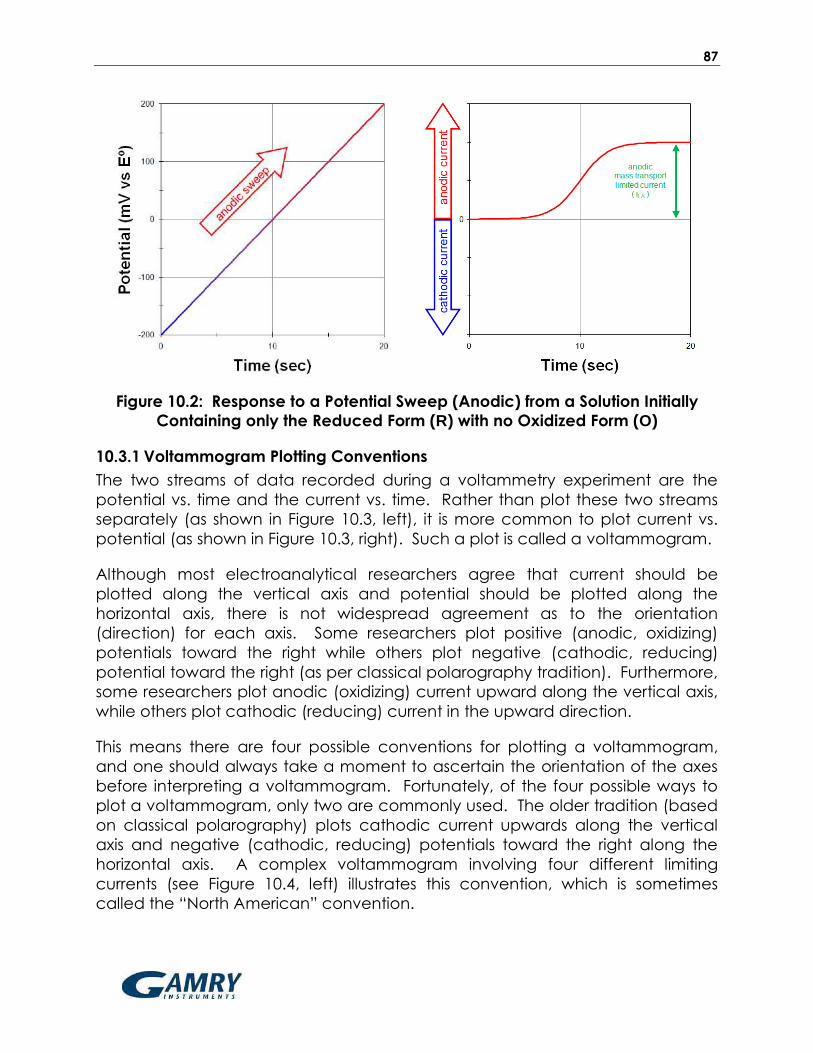
87
Figure 10.2: Response to a Potential Sweep (Anodic) from a Solution Initially
Containing only the Reduced Form (R) with no Oxidized Form (O)
10.3.1 Voltammogram Plotting Conventions
The two streams of data recorded during a voltammetry experiment are the
potential vs. time and the current vs. time. Rather than plot these two streams
separately (as shown in Figure 10.3, left), it is more common to plot current vs.
potential (as shown in Figure 10.3, right). Such a plot is called a voltammogram.
Although most electroanalytical researchers agree that current should be
plotted along the vertical axis and potential should be plotted along the
horizontal axis, there is not widespread agreement as to the orientation
(direction) for each axis. Some researchers plot positive (anodic, oxidizing)
potentials toward the right while others plot negative (cathodic, reducing)
potential toward the right (as per classical polarography tradition). Furthermore,
some researchers plot anodic (oxidizing) current upward along the vertical axis,
while others plot cathodic (reducing) current in the upward direction.
This means there are four possible conventions for plotting a voltammogram,
and one should always take a moment to ascertain the orientation of the axes
before interpreting a voltammogram. Fortunately, of the four possible ways to
plot a voltammogram, only two are commonly used. The older tradition (based
on classical polarography) plots cathodic current upwards along the vertical
axis and negative (cathodic, reducing) potentials toward the right along the
horizontal axis. A complex voltammogram involving four different limiting
currents (see Figure 10.4, left) illustrates this convention, which is sometimes
called the “North American” convention.

88
Figure 10.3: A Voltammogram is a Plot of Current versus Potential
The “North American” Convention The “European” Convention
Figure 10.4: Two Popular Voltammogram Plotting Conventions

89
The same data may be plotted using the “European” convention (see Figure
10.4, right). This convention plots anodic currents upward along the vertical axis
and more positive (anodic, oxidizing) potentials to the right along the horizontal
axis. The European convention is a more readily understood by those outside
the electroanalytical research community (because positive values are plotted
to the right along the horizontal axis).
The European convention is used throughout the remainder of this document.
Note that this choice also implies a mathematical sign convention for the
current. Specifically, positive current values are considered anodic, and
negative current values are considered cathodic in this document. This sign
convention is somewhat arbitrary, and electrochemical data processing
software available from various manufacturers may or may not use this sign
convention.
10.3.2 Measuring Limiting Currents
The theoretical voltammetric response from a rotating electrode is a symmetric
sigmoid-shaped wave (like the ideal voltammograms shown in Figure 10.3 and
Figure 10.4). A perfect sigmoid has a flat baseline current before the wave and
a flat limiting current plateau after the wave. The height of the wave (as
measured from the baseline current to the limiting current plateau) is the mass-
transport limited current.
In actual “real world” experiments, the wave may be observed on top of a
background current, and furthermore, the background current may be slightly
sloped (see Figure 10.5). This (undesired) background current may be due to
interference from oxidation or reduction of impurities or of the solvent itself. The
background current may also be due to capacitive charging and discharging
of the ionic double-layer that forms next to the polarized electrode surface.
When attempting to measure the (desired) Faradaic mass-transport limited
current at a rotating electrode, it is often necessary to account for the
(undesired, possibly sloping) background current. If the background current has
a constant slope across the entire voltammogram, then it is fairly easy to
extrapolate the sloping baseline to a point underneath the limiting current
plateau (see Figure 10.5, left). The limiting current is measured as the (vertical)
distance between the plateau and the extrapolated baseline. In
voltammograms where there is more than one wave, the plateau for the first
wave is used as the baseline for the second wave (see iLA2 in Figure 10.5, left).
In some cases, the slope of the background current is not constant across the
entire voltammogram. That is, the slope of the baseline leading up to the wave
can be different than the slope of the plateau after the wave. It can be very
difficult to discern exactly where to measure the limiting current along such a

90
voltammogram. One approach is to extrapolate the baseline forward through
the wave and also extrapolate the plateau backward through the wave. Then,
the limiting current is measured as the vertical distance between the baseline
and plateau at a point corresponding to the center of the voltammogram
(see iLA in Figure 10.5, right).
Figure 10.5: Sloping Backgrounds in Voltammograms
Figure 10.6: Voltammogram for a Solution Containing Both O and R
Finally, it should be noted that when the oxidized form (O) and the reduced
form (R) of a molecule or ion are both present in a solution at the same time, the
voltammogram is likely to exhibit both a cathodic and an anodic limiting current

91
(see Figure 10.6). It can be very difficult to measure the limiting current properly
in this case, especially if there is also a sloping background current. For this
reason, most experiments with rotating electrodes are conducted in solutions
where only one form of the molecule or ion is initially present.
10.4 Rotating Disk Electrode (RDE) Theory
The general theory describing the rotating disk electrode was originally
developed by Dr. Benjamin Levich in his landmark book[10] called
Physicochemical Hydrodynamics (Prentice-Hall). In 1962, this book was
translated from Russian to English, and researchers in the United States and the
United Kingdom rapidly built upon Dr. Levich’s seminal work. Dr. Stanley
Bruckenstein’s laboratory at the University of Minnesota (and later at the
University of Buffalo) helped to spread the theory and application of the rotating
disk electrode[9] to many other electroanalytical chemists, including Dr. John
Albery[12-17] (Oxford University) and Dr. Dennis Johnson[11] (Iowa State University).
Subsequent generations of researchers expanded on this initial work until the
rotating disk electrode became a mature tool for probing electrochemical
reaction kinetics.
The laminar flow at a rotating disk electrode conveys a steady stream of
material from the bulk solution to the electrode surface. While the bulk solution
far away from the electrode remains well-stirred by the convection induced by
rotation, the portion of the solution nearer to the electrode surface tends to
rotate with the electrode. Thus, if the solution is viewed from the frame of
reference of the rotating electrode surface, then the solution appears relatively
stagnant. This relatively stagnant layer is known as the hydrodynamic boundary
layer, and its thickness (δH) can be approximated,
2/1/ωv3.6δ H
in terms of the kinematic viscosity of the solution (v) and the angular rotation rate (ω = 2 π f / 60, where f is the rotation rate in revolutions per minute). In an
aqueous solution at a moderate rotation rate (~1000 RPM), the stagnant layer is
approximately 300 to 400 m thick.
Net movement of material to the electrode surface can be described
mathematically by applying general convection-diffusion concepts from fluid
dynamics. Mass transport of material from the bulk solution into the stagnant
layer occurs by convection (due to the stirring action of the rotating electrode).
But after the material enters the stagnant layer and moves closer to the
electrode surface, convection becomes less important and diffusion becomes
more important. Indeed, the final movement of an ion or molecule to the
electrode surface is dominated by diffusion across a very thin layer of solution
immediately adjacent to the electrode known as the diffusion layer.

92
The diffusion layer is much thinner than the hydrodynamic layer. The diffusion
layer thickness (δF) can be approximated as follows,
2/16/1 ωvD1.61δ 1/3FF
in terms of the diffusion coefficient (DF) of the molecule or ion. For a molecule or
ion with a typical diffusion coefficient (DF 10-5 cm2/sec) in an aqueous solution,
the diffusion layer is about twenty times thinner than the stagnant layer
(δF 0.05 δH).
The first mathematical treatment of convection and diffusion towards a rotating
disk electrode was given by Levich. Considering the case where only the
oxidized form of a molecule (or ion) of interest is initially present in the
electrochemical cell, the cathodic limiting current (iLC) observed at a rotating
disk electrode is given by the Levich equation,[2,10]
iLC = 0.620 n F A D2/3 ν –1/6 CO ω1/2
in terms of the concentration (CO) of the oxidized form in the solution, the
Faraday constant (F = 96485 coulombs per mole), the electrode area (A), the
kinematic viscosity of the solution (ν), the diffusion coefficient (D) of the oxidized
form, and the angular rotation rate (ω). Alternatively, when the solution initially
contains only the reduced form, the Levich equation for the anodic limiting
current (iLA) can be written as
iLA = 0.620 n F A D2/3 ν–1/6 CR ω1/2
where the concentration term (CR) is for the reduced form rather than the
oxidized form.
10.4.1 Levich Study
A Levich Study is a common experiment performed using a rotating disk
electrode in which a series of voltammograms is acquired over a range of
different rotation rates. For a simple electrochemical system where the rate of
the half reaction is governed only by mass transport to the electrode surface,
the overall magnitude of the voltammogram should increase with the square
root of the rotation rate (see Figure 10.7, left).
The currents measured during a Levich study are usually plotted against the
square root of the rotation rate on a graph called a Levich plot. As predicted
by the Levich equation, the limiting current (see red circles on Figure 10.7, right)
increases linearly with the square root of the rotation rate (with a slope of 0.620 n
F A D2/3 ν–1/6 C) and the line intercepts the vertical axis at zero. It is common to
choose a set of rotation rates that are multiples of perfect squares (such as 100,
400, 900, 1600 RPM, etc.) to facilitate construction of this plot.

93
Figure 10.7: Levich Study – Voltammograms at Various Rotation Rates
If the electrochemical half-reaction observed during a Levich study is a simple
and reversible half reaction (with no complications due to sluggish kinetics or
coupled chemical reactions), then the shapes of the mass-transport controlled
voltammograms will be sigmoidal regardless of the rotation rate. This means
that the current observed at any given potential along the voltammogram will
vary linearly with the square root of the rotation rate (see Figure 10.7, right). But,
it is important to remember that the Levich equation only applies to the limiting
current, not to the currents along the rising portion of the sigmoid.
Because the Levich equation only applies to the limiting current, the results from
a Levich experiment are typically presented as a simple plot of the limiting
current versus the square root of the rotation rate (see Figure 10.8, center).
Limiting Current
Levich Plot
Koutecky-Levich Plot
Figure 10.8: Levich Study – Limiting Current versus Rotation Rate

94
An alternate method of presenting the data from a Levich study is based on a
rearrangement of the Levich equation in terms of the reciprocal current.
2/1
6/13/2620.0
11
CDAFniL
A plot of reciprocal current versus the reciprocal square root of the angular
rotation rate (see Figure 10.8, right) is called a Koutecky-Levich[2,11] plot. Again,
for a simple and reversible half reaction with no complications the data fall
along a straight line that intercepts the vertical axis at zero. If the line intercepts
the vertical axis above zero, however, this is a strong indication that the half-
reaction is limited by sluggish kinetics rather than by mass transport.
Figure 10.9: Koutecky Levich Study – Voltammograms with Sluggish Kinetics
10.4.2 Koutecky-Levich Analysis
When the rate of a half reaction occurring at an electrode surface is limited by
a combination of mass transport and sluggish kinetics, it is often possible to use a
rotating disk electrode to elucidate both the mass transport parameters (such as
the diffusion coefficient) and the kinetic parameters (such as the standard rate
constant, kº) from a properly designed Levich study. A full treatment of this kind
of analysis[11] is beyond the scope of this document, but the following is a
general description of how to extract kinetic information from a set of rotating
disk voltammograms.
When the electron transfer process at an electrode surface exhibits sluggish
kinetics, the voltammogram appears stretched out along the potential axis and
the shape of the sigmoidal wave is slightly distorted. Comparing a set of
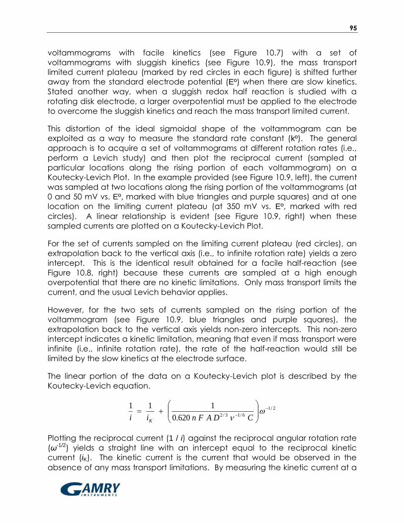
95
voltammograms with facile kinetics (see Figure 10.7) with a set of
voltammograms with sluggish kinetics (see Figure 10.9), the mass transport
limited current plateau (marked by red circles in each figure) is shifted further
away from the standard electrode potential (Eº) when there are slow kinetics.
Stated another way, when a sluggish redox half reaction is studied with a
rotating disk electrode, a larger overpotential must be applied to the electrode
to overcome the sluggish kinetics and reach the mass transport limited current.
This distortion of the ideal sigmoidal shape of the voltammogram can be
exploited as a way to measure the standard rate constant (kº). The general
approach is to acquire a set of voltammograms at different rotation rates (i.e.,
perform a Levich study) and then plot the reciprocal current (sampled at
particular locations along the rising portion of each voltammogram) on a
Koutecky-Levich Plot. In the example provided (see Figure 10.9, left), the current
was sampled at two locations along the rising portion of the voltammograms (at
0 and 50 mV vs. Eº, marked with blue triangles and purple squares) and at one
location on the limiting current plateau (at 350 mV vs. Eº, marked with red
circles). A linear relationship is evident (see Figure 10.9, right) when these
sampled currents are plotted on a Koutecky-Levich Plot.
For the set of currents sampled on the limiting current plateau (red circles), an
extrapolation back to the vertical axis (i.e., to infinite rotation rate) yields a zero
intercept. This is the identical result obtained for a facile half-reaction (see
Figure 10.8, right) because these currents are sampled at a high enough
overpotential that there are no kinetic limitations. Only mass transport limits the
current, and the usual Levich behavior applies.
However, for the two sets of currents sampled on the rising portion of the
voltammogram (see Figure 10.9, blue triangles and purple squares), the
extrapolation back to the vertical axis yields non-zero intercepts. This non-zero
intercept indicates a kinetic limitation, meaning that even if mass transport were
infinite (i.e., infinite rotation rate), the rate of the half-reaction would still be
limited by the slow kinetics at the electrode surface.
The linear portion of the data on a Koutecky-Levich plot is described by the
Koutecky-Levich equation.
2/1
6/13/2620.0
111
CDAFnii K
Plotting the reciprocal current (1 / i) against the reciprocal angular rotation rate
(ω-1/2) yields a straight line with an intercept equal to the reciprocal kinetic
current (iK). The kinetic current is the current that would be observed in the
absence of any mass transport limitations. By measuring the kinetic current at a
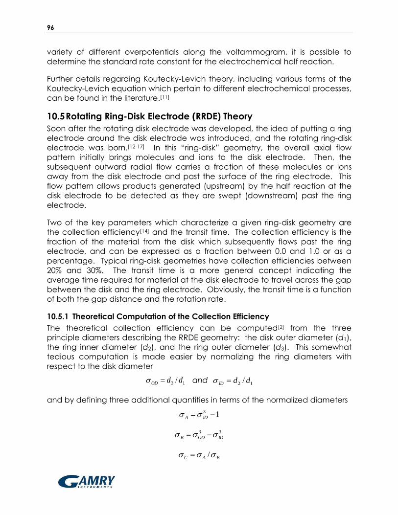
96
variety of different overpotentials along the voltammogram, it is possible to
determine the standard rate constant for the electrochemical half reaction.
Further details regarding Koutecky-Levich theory, including various forms of the
Koutecky-Levich equation which pertain to different electrochemical processes,
can be found in the literature.[11]
10.5 Rotating Ring-Disk Electrode (RRDE) Theory
Soon after the rotating disk electrode was developed, the idea of putting a ring
electrode around the disk electrode was introduced, and the rotating ring-disk
electrode was born.[12-17] In this “ring-disk” geometry, the overall axial flow
pattern initially brings molecules and ions to the disk electrode. Then, the
subsequent outward radial flow carries a fraction of these molecules or ions
away from the disk electrode and past the surface of the ring electrode. This
flow pattern allows products generated (upstream) by the half reaction at the
disk electrode to be detected as they are swept (downstream) past the ring
electrode.
Two of the key parameters which characterize a given ring-disk geometry are
the collection efficiency[14] and the transit time. The collection efficiency is the
fraction of the material from the disk which subsequently flows past the ring
electrode, and can be expressed as a fraction between 0.0 and 1.0 or as a
percentage. Typical ring-disk geometries have collection efficiencies between
20% and 30%. The transit time is a more general concept indicating the
average time required for material at the disk electrode to travel across the gap
between the disk and the ring electrode. Obviously, the transit time is a function
of both the gap distance and the rotation rate.
10.5.1 Theoretical Computation of the Collection Efficiency
The theoretical collection efficiency can be computed[2] from the three
principle diameters describing the RRDE geometry: the disk outer diameter (d1),
the ring inner diameter (d2), and the ring outer diameter (d3). This somewhat
tedious computation is made easier by normalizing the ring diameters with
respect to the disk diameter
13 / ddOD and 12 / ddID
and by defining three additional quantities in terms of the normalized diameters
13 IDA
33
IDODB
BAC /

97
If a complex function, G(x), is defined as follows,
3
12arctan
2
3
1
1ln
4
3
4
1)(
3/133/1 x
x
xxG
then the theoretical collection efficiency (Ntheoretical) for a rotating ring-disk
electrode is given by the following equation:
)()()(1 323/23/22
ODCODABCBODltheoretica GGGN
10.5.2 Empirical Measurement of the Collection Efficiency
Direct computation of the theoretical collection efficiency is possible using the
above relationship if the actual machined dimensions of the disk and ring are
known for a particular RRDE. In practice, the actual RRDE dimensions may not
be known due to uncertainties in the machining process and changes in the
dimensions induced by electrode polishing or temperature cycling. For this
reason, it is common practice to empirically measure the collection efficiency
using a well-behaved redox system rather than to rely upon a computed value.
The ferrocyanide/ferricyanide half reaction is a simple, single-electron, reversible
half reaction that is often used as the basis for measuring collection efficiency.
The RRDE is placed in a solution containing a small concentration (~10 mM) of
potassium ferricyanide, K3Fe(CN)6, in a suitable aqueous electrolyte solution
(such as 1.0 M potassium nitrate, KNO3) and is operated at rotation rates
between 500 and 2000 RPM. Initially, both the ring and the disk electrodes are
held at a sufficiently positive potential that no reaction occurs. Then, the
potential of the disk electrode is slowly swept (~50 mV/sec) towards more
negative potentials, and a cathodic current is observed which corresponds to
the reduction of ferricyanide to ferrocyanide at the disk.
4
6
3
6 )()( CNFeeCNFe
(reduction of ferricyanide to ferrocyanide at disk)
As ferricyanide is reduced at the disk electrode, the ferrocyanide generated by
this process is swept outward (radially) away from the disk electrode and toward
the ring electrode. The ring electrode is held constant at a positive (oxidizing)
potential throughout the experiment. Some (but not all) of the ferrocyanide
generated at the disk travels close enough to the ring electrode that it is
oxidized back to ferricyanide. Thus, an anodic current is observed at the ring
electrode due to the oxidation of ferrocyanide to ferricyanide at the ring.
eCNFeCNFe 3
6
4
6 )()(
(oxidation of ferrocyanide to ferricyanide at ring)

98
Figure 10.10: Rotating Ring-Disk Voltammograms at Various Rotation Rates
The measured ratio of the ring (anodic) limiting current to the disk (cathodic)
limiting current is the empirical collection efficiency. As the rotation rate
increases, both the disk and the ring currents increase (see Figure 10.10).
Because both the anodic and cathodic limiting currents are proportional to the
square root of the rotation rate, the empirical collection efficiency is expected
to be independent of the rotation rate.
Once the collection efficiency value has been established empirically for a
particular RRDE, it can be treated as a property of that particular RRDE, even if
the RRDE is used to study a different half reaction in a different solution on a
different day. Although the empirically measured collection efficiency (Nempirical)
is a ratio of two currents with opposite mathematical signs (anodic and
cathodic), the collection efficiency is always expressed as a positive number.
DISKLIMITINGRINGLIMITINGempirical iiN ,, /
10.5.3 Generator/Collector Experiments
When a molecule or ion is oxidized or reduced at an electrode, it is often
transformed into an unstable intermediate chemical species which, in turn, is
likely to undergo additional chemical changes. The intermediate may have a
long enough lifetime that it is capable of moving to the ring electrode and
being detected. Or, the intermediate may be so unstable that it decays away

99
before it can be detected at the ring. Consider the following reaction scheme
at a rotating ring-disk electrode:
XenA
1 (reduction of A to unstable intermediate X at disk electrode)
ZX k (chemical decay of X to electrochemically inactive Z)
enAX 1 (oxidation of X back to A at ring electrode)
In the above scheme, the disk electrode is poised at a potential where A is
reduced to X, and the cathodic limiting current observed at the disk (iDISK) is a
measure of how much X is being “generated” at the disk electrode. At the
same time, the ring electrode is poised at a more positive potential where X is
oxidized back to A, and the anodic limiting current observed at the ring (iRING) is
a measure of much X is being “collected” at the ring. There is also a competing
chemical reaction which is capable of eliminating X before it has a chance to
travel from the disk to the ring.
The ratio of the ring current to the disk current under these conditions is called
the apparent collection efficiency (Napparent).
DISKRINGapparent iiN /
By comparing the apparent collection efficiency (Napparent) to the previously
measured empirical collection efficiency (Nempirical) for the same RRDE, it is
possible to deduce the rate at which the competing chemical pathway is
converting X to Z. That is, it is possible to use an RRDE “generator/collector”
experiment to measure the kinetic behavior of unstable electrochemical
intermediates.
Whenever Napparent Nempirical, it is an indication that the decay rate of the
intermediate (via the X→Z pathway) is small with respect to the transit time
required for X to travel from the disk to the ring. One way to shorten the transit
time is to spin the RRDE at a faster rate. At high rotation rates, the apparent
collection efficiency should approach the empirical collection efficiency.
Conversely, at slower rotation rates, the apparent collection efficiency may be
smaller (Napparent < Nempirical) because some of the intermediate is consumed by
the competing chemical pathway before X can travel to the ring.
By recording a series of rotating ring-disk voltammograms at different rotation
rates and analyzing the results, it is possible to estimate the rate constant (k)
associated with the intermediate chemical decay pathway. Various
relationships have been proposed for this kind of analysis,[2] and one of the
simplest is shown below

100
k
DN
N
apparent
empirical
3/1
28.11
A plot of the ratio of the empirical to the apparent collection efficiency versus
the reciprocal angular rotation rate should be linear. The slope of such a plot
can yield the rate constant if the kinematic viscosity (v) and the diffusion
coefficient (D) are known.
10.5.4 Comparing Two Competing Pathways
Sometimes the intermediate generated by an electrochemical process can
decay via two different pathways. As long as one of these pathways leads to
an electrochemically active chemical species that can be detected at the ring,
it is possible to determine which decay pathway is favored. Consider the
following scheme:
XenA
1 (reduction of A to unstable intermediate X at disk electrode)
ZXk 1 (fast chemical decay of X to electrochemically inactive Z)
YXk 2 (fast chemical decay of X to electrochemically active Y)
enBY 2 (detection of Y at ring electrode via oxidation of Y to B)
In the above scheme, the disk electrode is poised at a potential where A is
reduced to X, and the cathodic limiting current observed at the disk (iDISK) is a
measure of how much X is being “generated” at the disk electrode. The
intermediate X is unstable, and as it is swept away from the disk and toward the
ring, it rapidly decays to either Y or Z. By the time these species reach the ring,
all of the X has decayed away, and the solution in contact with the ring
contains both Y and Z. The species Z is electrochemically inactive and cannot
be detected by the ring, but the species Y is active. By carefully poising the ring
electrode at a potential appropriate for detecting Y (in this case, by oxidizing Y
to B), it is possible for the ring to “collect” any Y which arrives at the surface of
the ring.
The ratio of the ring current (due to Y being detected at the ring) to the disk
current (due to X being generated at the disk) reveals the extent to which the
X→Y pathway is favored in comparison to the X→Z pathway. The fraction of
the decay by the X→Y pathway (θXY) can be computed as follows.
DISK
RING
empirical
XYi
i
n
n
N
2
11
Note in the above equation that the fraction (n1/n2) carefully accounts for any
difference in the number of electrons involved in the disk half reaction and the

101
number of electrons involved when detecting Y at the ring electrode. Schemes
involving more complex stoichiometry may require additional correction factors.
The most commonly studied reaction at the RRDE is undoubtedly the oxygen
reduction reaction (ORR).[24-34] When oxygen (O2) is dissolved in acidic media
and reduced at a platinum electrode, one pathway leads to water as the
ultimate reduction product while the other pathway leads to the formation of
peroxide anions. In the context of hydrogen fuel cell research, the pathway
which leads to water is preferred, and it is commonly called the four-electron
pathway. The path to peroxide formation is called the two-electron pathway,
and it is undesirable for a number of reasons, including the fact that peroxide
can damage various polymer membrane materials found in a fuel cell. Further
details on how to use an RRDE “generator/collector” experiment to distinguish
between the two-electron and four-electron ORR pathways can be found in the
electrochemical literature.[24,27]
10.6 Rotating Cylinder Electrode (RCE) Theory
The rotating disk and ring-disk electrodes were developed primarily as a result of
academic electroanalytical chemistry research. In contrast, the theory for the
rotating cylinder electrode (RCE) was developed by industrial researchers[37-39] in
the corrosion and electroplating communities. While the flow of solution at a
rotating disk (or ring-disk) is laminar over a wide range of rotation rates, the flow
at the surface of a rotating cylinder is turbulent[22] at all but the slowest rotation
rates. Thus, the RCE is an excellent tool for creating and controlling turbulent
flow conditions in the laboratory, and it is most commonly used to mimic
turbulent corrosion conditions found in large scale industrial settings such as
oilfield pipeline corrosion.[47-60]
The turbulent flow at a rotating cylinder electrode conveys material from the
bulk solution towards the electrode surface. While the bulk solution remains well
stirred by the main vortex induced by the rotating electrode, the layer of
solution adjacent to the cylinder surface tends to rotate with the electrode.
Thus, a high shear condition is set up at the surface of the rotating cylinder,
spinning off smaller Taylor vortices adjacent to the rotating electrode.
Net movement of material to the surface of a rotating cylinder was first
characterized by Eisenberg[18-19] in 1954 (about the same time that Levich was
describing the rotating disk electrode). Eisenberg’s work eventually led to the
Eisenberg equation which gives the limiting current at a rotating cylinder
electrode
7.0344.0644.04.00487.0 CDdAFni cylL

102
in terms of the concentration (C) and diffusion coefficient (D) of the molecule or
ion being studied, the Faraday constant (F = 96485 coulombs per mole), the
electrode area (A), the diameter of the cylinder (dcyl), the kinematic viscosity of
the solution (ν), and the angular rotation rate (ω = 2 π f / 60, where f is the
rotation rate in revolutions per minute). In the years since Eisenberg’s initial work
with the rotating cylinder, additional work by Gabe, Kear, Walsh, and Silverman
has described industrial applications of the RCE.[18-23,35-60]
10.7 References 1. PT Kissinger and WR Heineman, Laboratory techniques in electroanalytical chemistry, Marcel
Dekker, New York (1996).
2. AJ Bard and LR Faulkner, Electrochemical Methods-Fundamentals and Applications, 2nd
Edition, John Wiley & Sons, New York (2000) Chapter 9.
3. DC Johnson, SG Weber, AM Bond, RM Wightman, RE Shoup and IS Krull, Electroanalytical
voltammetry in flowing solutions, Analytica Chimica Acta 180 (1986) 187-250.
4. H Gunasingham and B Fleet, Wall-jet electrode in continuous monitoring voltammetry,
Analytical Chemistry 55 (1983) 1409-1414.
5. JV Macpherson and PR Unwin, Hydrodynamic Modulation Voltammetry with an Oscillating
Microjet Electrode, Analytical Chemistry 71 (1999) 4642.
6. IE Henley, K Yunus and AC Fisher, Voltammetry under Microfluidic Control: Computer-Aided
Design Development and Application of Novel Microelectrochemical Reactors, J. of Physical
Chemistry B 107 (2003) 3878-3884.
7. KW Pratt and DC Johnson, Vibrating wire electrodes—I. Literature review, design and
evaluation, Electrochemica Acta 27 (1982) 1013-1021.
8. C Hagan and LA Coury, Comparison of hydrodynamic voltammetry implemented by
sonication to a rotating disk electrode, Analytical Chemistry 66 (1994) 399-405.
9. S Bruckenstein and B Miller, Unraveling reactions with rotating electrodes, Acc. Chem. Res. 10
(1977) 54-61.
10. VG Levich, Physicochemical Hydrodynamics, Prentice-Hall, Upper Saddle River NJ (1962).
11. S Treimer, A Tanga and DC Johnson, Consideration of the Application of Koutecky-Levich
Plots in the Diagnoses of Charge-Transfer Mechanisms at Rotated Disk Electrodes,
Electroanalysis 14 (2002) 165-171.
12. WJ Albery and ML Hitchman, Ring-Disc Electrodes, Clarendon Press, Oxford (1971).
13. WJ Albery, Ring-disc electrodes. Part 1.— A new approach to the theory, Trans. Faraday Soc.
62 (1966) 1915-1919.
14. WJ Albery and S Bruckenstein, Ring-disc electrodes. Part 2.— Theoretical and experimental
collection efficiencies, Trans. Faraday Soc. 62 (1966) 1920-1931.
15. WJ Albery, S Bruckenstein and DT Napp, Ring-disc electrodes. Part 3.— Current-voltage
curves at the ring electrode with simultaneous currents at the disc electrode, Trans. Faraday
Soc. 62 (1966) 1932-1937.
16. WJ Albery, S Bruckenstein and DC Johnson, Ring-disc electrodes. Part 4.— Diffusion layer
titration curves, Trans. Faraday Soc. 62 (1966) 1938-1945.
17. WJ Albery, Ring-disc electrodes. Part 5.— First-order kinetic collection efficiencies at the ring
electrode, Trans. Faraday Soc. 62 (1966) 1946-1954.
18. M Eisenberg, CW Tobias and CR Wilke, Ionic Mass Transfer and Concentration Polarization at
Rotating Electrodes, Journal of the Electrochemical Society 101 (1954) 306.
19. M Eisenberg, CW Tobias and CR Wilke, Chem. Eng. Progr. Symp. Ser. 51 (1955) 1.

103
20. DR Gabe, Rotating Cylinder Electrode, J. Appl. Electrochem. 4 (1974) 91.
21. DR Gabe and DJ Robinson, Mass Transfer in a Rotating Cylinder Cell–I. Laminar Flow,
Electrochemica Acta 17 (1972) 1121.
22. DR Gabe and DJ Robinson, Mass Transfer in a Rotating Cylinder Cell–II. Turbulent Flow,
Electrochemica Acta 17 (1972) 1129.
23. DR Gabe and FC Walsh, The Rotating Cylinder Electrode: A Review of Development, J. Appl.
Electrochem. 13 (1983) 3.
24. Y Garsany, OA Baturina, KE Swider-Lyons and SS Kocha, Experimental Methods for
Quantifying the Activity of Platinum Electrocatalysts for the Oxygen Reduction Reaction,
Analytical Chemistry 82 (2010) 6321-6328.
25. HA Gasteiger, SS Kocha, B Sompalli and FT Wagner, Activity benchmarks and requirements
for Pt, Pt-alloy, and non-Pt oxygen reduction catalysts for PEMFCs, Applied Catalysis B:
Environmental 56 (2005) 9-35.
26. UA Paulus, A Wokauna, GG Scherera, TJ Schmidt, V Stamenkovic, NM Markovic and PN Ross,
Oxygen reduction on high surface area Pt-based alloy catalysts in comparison to well
defined smooth bulk alloy electrodes, Electrochimica Acta 47 (2002) 3787-3798.
27. UA Paulus, TJ Schmidt, HA Gasteiger and RJ Behm, Oxygen reduction on a high-surface area
Pt/Vulcan carbon catalyst: a thin-film rotating ring-disk electrode study, J. of
Electroanalytical Chem. 495 (2001) 134-145.
28. TJ Schmidt, UA Paulus, HA Gasteiger and RJ Behm, The oxygen reduction reaction on a
Pt/carbon fuel cell catalyst in the presence of chloride anions, J. of Electroanalytical Chem.
508 (2001) 41-47.
29. G Brisard, N Bertranda, PN Ross and NM Markovic, Oxygen reduction and hydrogen
evolution–oxidation reactions on Cu(hkl) surfaces, J. of Electroanalytical Chem. 480 (2000)
219-224.
30. L Geniès, R Faure and R Durand, Electrochemical reduction of oxygen on platinum
nanoparticles in alkaline media, Electrochimica Acta 44 (1998) 1317-1327.
31. E Higuchia, H Uchidab and M Watanabe, Effect of loading level in platinum-dispersed
carbon black electrocatalysts on oxygen reduction activity evaluated by rotating disk
electrode. J. of Electroanalytical Chem. 583 (2005) 69-76.
32. ZD Weia, SH Chanb, LL Lia, HF Caia, ZT Xiab and CX Sunc, Electrodepositing Pt on a Nafion-
bonded carbon electrode as a catalyzed electrode for oxygen reduction reaction,
Electrochimica Acta 50 (2005) 2279-2287.
33. S Marcotte, D Villers, N Guillet, L Roué and JP Dodelet, Electroreduction of oxygen on Co-
based catalysts: determination of the parameters affecting the two-electron transfer
reaction in an acid medium, Electrochimica Acta 50 (2004) 179-188.
34. S Durón, R Rivera-Noriega, P Nkeng, G Poillerat and O Solorza-Feria, Kinetic study of oxygen
reduction on nanoparticles of ruthenium synthesized by pyrolysis of Ru3(CO)12, J. of
Electroanalytical Chem. 566 (2004) 281-289.
35. DR Gabe and FC Walsh, Enhanced Mass Transfer at the Rotating Cylinder Electrode–I.
Characterization of a Smooth Cylinder and Roughness Development in Solutions of Constant
Concentration, J. Appl. Electrochem. 14 (1984) 555.
36. DR Gabe and FC Walsh, Enhanced Mass Transfer at the Rotating Cylinder Electrode–II.
Development of Roughness for Solutions of Decreasing Concentration, J. Appl. Electrochem.
14 (1984) 565.
37. DR Gabe and FC Walsh, Enhanced Mass Transfer at the Rotating Cylinder Electrode–III. Pilot
and Production Plant Experience, J. Appl. Electrochem. 15 (1985) 807.
38. DR Gabe and PA Makanjuola, Enhanced Mass Transfer Using Roughened Rotating Cylinder
Electrodes in Turbulent Flow, J. Appl. Electrochem. 17 (1987) 370.

104
39. DR Gabe, GD Wilcox, J Gonzalez-Garcia and FC Walsh, The Rotating Cylinder Electrode: Its
Continued Development and Application, J. Appl. Electrochem. 28 (1998) 759.
40. G Kear, BD Barker, K Stokes and FC Walsh, Flow Influenced Electrochemical Corrosion of
Nickel Aluminum Bronze – Part I. Cathodic Polarization, J. Appl. Electrochem. 34 (2004) 1235.
41. G Kear, BD Barker, K Stokes and FC Walsh, Flow Influenced Electrochemical Corrosion of
Nickel Aluminum Bronze – Part II. Anodic Polarization and Derivation of the Mixed Potential, J.
Appl. Electrochem. 34 (2004) 1241.
42. Q Lu, MM Stack and CR Wiseman, AC Impedance Spectroscopy as a Technique for
Investigating Corrosion of Iron in Hot Flowing Bayer Liquors, J. Appl. Electrochem. 31 (2001)
1373.
43. JM Maciel and SML Agostinho, Use of a Rotating Cylinder Electrode in Corrosion Studies of a
90/10 Cu–Ni Alloy in 0.5M H2SO4 Media, J. Appl. Electrochem. 30 (2000) 981.
44. JM Grau and JM Bisang, Mass Transfer Studies at Rotating Cylinder Electrodes of Expanded
Metal, J. Appl. Electrochem. 35 (2005) 285.
45. A Eklund and D Simonsson, Enhanced Mass Transfer to a Rotating Cylinder Electrode with
Axial Flow, J. Appl. Electrochem. 18 (1988) 710.
46. KD Efird, EJ Wright, JA Boros and TG Hailey, Correlation of Steel Corrosion in Pipe Flow with Jet
Impingement and Rotating Cylinder Tests, Corrosion 49 (1993) 992.
47. DC Silverman, Rotating Cylinder Electrode for Velocity Sensitivity Testing, Corrosion 40 (1984)
220.
48. DC Silverman and ME Zerr, Application of the Rotating Cylinder Electrode – E-Brite® 26-1 in
Concentrated Sulfuric Acid, Corrosion 42 (1986) 633.
49. DC Silverman, Rotating Cylinder Electrode – Geometry Relationships for Prediction of
Velocity-Sensitive Corrosion, Corrosion 44 (1988) 42.
50. DC Silverman, Corrosion Prediction in Complex Environments using Electrochemical
Impedance Spectroscopy, Electrochimica Acta 38 (1993) 2075.
51. DC Silverman, On Estimating Conditions for Simulating Velocity-Sensitive Corrosion in the
Rotating Cylinder Electrode, Corrosion 55 (1999) 1115.
52. DC Silverman, Technical Note: Simplified Equation for Simulating Velocity-Sensitive Corrosion
in the Rotating Cylinder Electrode at Higher Reynolds Numbers, Corrosion 59 (2003) 207.
53. DC Silverman, The Rotating Cylinder Electrode for Velocity-Sensitive Corrosion – A Review,
Corrosion 60 (2004) 1003.
54. DC Silverman, Technical Note: Conditions for Similarity of Mass-Transfer Coefficients and Fluid
Shear Stresses between the Rotating Cylinder Electrode and Pipe, Corrosion 61 (2005) 515.
55. G Wranglen, J Berendson and G Karlberg, Apparatus for Electrochemical Studies of
Corrosion Processes in Flowing Systems, in Physico-Chemical Hydrodynamics, edited by
B Spalding (London: Adv. Publications, 1977) 461.
56. RA Holser, G Prentice, RB Pond and R Guanti, Use of Rotating Cylinder Electrodes to Simulate
Turbulent Flow Conditions in Corrosion Systems, Corrosion 46 (1990) 764.
57. TY Chen, AA Moccari and DD Macdonald, Development of Controlled Hydrodynamic
Techniques for Corrosion Testing, Corrosion 48 (1992) 239.
58. S Nesic, GT Solvi and S Skjerve, Comparison of Rotating Cylinder and Loop Methods for
Testing CO2 Corrosion Inhibitors, British Corrosion Journal 32 (1997) 269.
59. ASTM G 170, Standard Guide for Evaluating and Qualifying Oilfield and Refinery Corrosion
Inhibitors in the Laboratory (2001).
60. ASTM G 185, Standard Practice for Evaluating and Qualifying Oil Field and Refinery Corrosion
Inhibitors Using the Rotating Cylinder Electrode (2006).

105
11 Glossary
Anodic Current Flow of charge at an electrode as a result of an
oxidation reaction occurring at the electrode
surface. For a working electrode immersed in a test
solution, an anodic current corresponds to flow of
electrons out of the solution and into the electrode.
Banana Cable A banana cable is a single-wire (one conductor)
signal cable often to make connections between
various electronic instruments. Each end of the
cable has a banana plug. The plug consists of a
cylindrical metal pin about 25 mm (one inch) long,
with an outer diameter of about 4 mm, which can
be inserted into a matching banana jack.
Banana Jack Female banana connector
Banana Plug Male banana connector
BNC Connector The BNC (Bayonet Neill-Concelman) connector is a
very common type of RF connector used for
terminating coaxial cable.
Brush Contacts Electrical contact to the rotating shaft is
accomplished by means of silver-carbon brush
contacts. These brushes are spring loaded to assure
that they are firmly pressed against the rotating shaft
at all times.
Cathodic Current Flow of charge at an electrode as a result of an
reduction reaction occurring at the electrode
surface. For a working electrode immersed in a test
solution, a cathodic current corresponds to flow of
electrons out of the electrode and into the solution.
106
Coaxial Cable Coaxial cable, or coax, is an electrical cable with an
inner conductor surrounded by a flexible, tubular
insulating layer, surrounded by a tubular conducting
shield. The term coaxial comes from the inner
conductor and the outer shield sharing the same
geometric axis. Coaxial cable is often used to carry
signals from one instrument to another in situations
where it is important to shield the signal from
environmental noise sources.
Collection Efficiency In the context of rotating ring-disk voltammetry, the
collection efficiency is a measure of the amount of
material which is generated at the disk electrode
which ultimately makes its way to the ring electrode.
It is often expressed as a percentage, and typical
collection efficiencies fall between 20% and 30%.
Collection Experiment An experiment with a rotating ring-disk electrode
where the ring potential is held constant while the
disk potential is swept slowly between two limits.
Convection Convection is the movement of molecules or ions
through a liquid solution as a result of bulk movement
of the solution. Such bulk movement may be due to
stirring the solution or due to vibrations or thermal
gradients in the solution.
Counter Electrode The counter electrode, often also called the auxiliary
electrode, is one of three electrodes found in a
typical three-electrode voltammetry experiment.
The purpose of the counter electrode is to help carry
the current across the solution by completing the
circuit back to the potentiostat.
Cyclic Voltammetry An electroanalytical method where the working
electrode potential is repeatedly swept back and
forth between two extremes while the working
electrode current is measured.
Cylinder Insert Most rotating cylinder electrode tips are designed to
accept cylinder inserts fabricated from various alloys
of interest to corrosion scientists.

107
Diffusion In the context of electrochemistry in liquid solutions,
diffusion is a time-dependent process consisting of
random motion of ions or molecules in solution which
leads to the statistical distribution of these species,
gradually spreading the ions and molecules through
the solution.
Diffusion Coefficient A factor of proportionality representing the amount
of substance diffusing across a unit area through a
unit concentration gradient in unit time.
Diffusion Layer Mass transport to a rotating electrode occurs via a
combination of convection and diffusion. As
material approaches the electrode, diffusion
dominates over convection as the principle means
of transport. Across the very thin layer of solution
immediately adjacent to the electrode, diffusion is
essentially the only means of mass transport. This thin
layer is known as the diffusion layer. The diffusion
layer should not be confused with the stagnant
layer. The diffusion layer exists entirely within the
thicker stagnant layer (see also Stagnant Layer).
Disk Insert Some rotating disk and ring-disk electrode tips are
designed to accept interchangeable disk inserts
fabricated from various precious metals and
advanced carbon materials.
Eisenberg Equation The Eisenberg equation describes the mass transfer
limited current at a rotating cylinder electrode.
Electroactive An adjective used to describe a molecule or ion
capable of being oxidized or reduced at an
electrode surface.
Electrode An electrode is an electrical conductor used to
make contact with a nonmetallic part of a circuit.
Electrode Materials Common electrode materials used to fabricate
rotating disk and ring-disk electrodes are gold,
platinum, and glassy carbon. Rotating cylinder
electrodes are usually made from various alloys of
steel, aluminum, or brass.

108
Faradaic Current
Forced Convection
Half-Reaction
Hydrodynamic Layer
Hydrodynamic
Voltammetry
Insulating Materials
Laminar Flow
Levich Equation
Levich Study
Levich Plot
Linear Polarization
Resistance
The portion of the current observed in an
electroanalytical experiment that can be attributed
to one or more redox processes occurring at an
electrode surface.
Active stirring or pumping of a liquid solution.
A balanced chemical equation showing how various
molecules or ions are being reduced (or oxidized) at
an electrode surface.
(see the definition of stagnant layer)
A family of electroanalytical methods based upon
precise control of solution flow coupled with rigorous
mathematical models.
Chemically resistant and electrically insulating
polymers commonly used to fabricate rotating
electrodes include PTFE, PEEK (poly ether ether
ketone), and KEL-F.
Laminar flow, sometimes known as streamline flow,
occurs when a fluid flows in parallel layers, with no
disruption between the layers.
The Levich equation describes the mass transfer
limited current at a rotating disk electrode.
Experiment using a rotating disk electrode in which a
series of voltammograms are acquired over a range
of rotation rates.
A plot of limiting current vs. square root of rotation
rate from a Levich study.
Term used in corrosion science for an experiment in
which the electrode potential is changed from an
initial value to final value at a slow and constant
rate. This technique is similar to linear sweep
voltammetry, but the sweep rates are much slower,
and the results are plotted differently.

109
Linear Sweep
Voltammetry
Experiment in which the working electrode potential
is swept from initial value to final value at a constant
rate while the current is measured.
Mass Transport
Limited Current
The current corresponding to the maximum mass
transfer rate of an ion or molecule to an electrode
surface.
Migration In an electroanalytical context, the term migration
refers to the movement of ions across a solution
under the influence of an electric field.
Non-Faradaic Current The portion of the current observed in an
electroanalytical experiment that cannot be
attributed to any redox processes occurring at an
electrode surface.
Overpotential The overpotential is the difference between the
formal potential of a half reaction and the potential
presently being applied to the working electrode.
Oxidation Removal of electrons from an ion or molecule.
Quiescent Solution A solution in which there is little or no convection.
Redox An adjective used to describe a molecule, ion, or
process associated with an electrochemical
reaction.
Reduction Addition of electrons to an ion or molecule.
Reference Electrode A reference electrode has a stable and well-known
thermodynamic potential. The high stability of the
electrode potential is usually reached by employing
a redox system with constant (buffered or saturated)
concentrations of the ions or molecules involved in
the redox half reaction.
Reynolds Number In fluid mechanics, the Reynolds number is a
dimensionless number that gives a measure of the
ratio of inertial forces to viscous forces and
consequently quantifies the relative importance of
these two types of forces for given flow conditions.

110
Rotation Rate The rate at which a rotating electrode rotates.
Experimentally, this is usually expressed in RPM, but in
theoretical equations, the rotation rate is usually
expressed in radians per second.
Shielding Experiment An experiment with a rotating ring-disk electrode
where the disk potential is held constant while the
ring potential is swept slowly between two limits.
Stagnant Layer At a rotating electrode, the portion of the solution
near the electrode tends to rotate at nearly the
same speed as the electrode surface. This layer of
solution is known as the stagnant layer (or, in the
context of fluid dynamics, the stagnant layer is more
properly called the hydrodynamic layer). Mass
transport across the stagnant layer occurs by a
combination of convection and diffusion, with
diffusion dominating as the material travels closer to
the electrode surface (see also Diffusion Layer).
Standard
Electrode
Potential
A thermodynamic quantity expressing the free
energy of a redox half reaction in terms of electric
potential.
Sweep Rate Rate at which the electrode potential is changed
when performing a sweep voltammetry method
such as cyclic voltammetry.
Three-Electrode Cell A common electrochemical cell arrangement
consisting of a working electrode, a reference
electrode, and a counter electrode.
Transit Time In the context of rotating ring-disk voltammetry, the
transit time is the average amount of time required
for material generated at the disk electrode to be
swept over to the ring electrode.
Turbulent Flow Chaotic (non-laminar) flow of solution.
Voltammogram A plot of current vs. potential from an
electroanalytical experiment in which the potential is
swept back and forth between two limits.

111
Window Experiment An experiment with a rotating ring-disk electrode
where the disk potential is swept slowly between two
limits, and the ring potential is swept in the same
manner as the disk potential but with a constant
offset between the ring and disk potentials.
Working Electrode The electrode at which the redox process of interest
occurs. While there may be many electrodes in an
electrochemical cell, the focus of an experiment is
typically only on a particular half reaction occurring
at the working electrode.