Embed Size (px)
Citation preview

RD-R2i 791 FINITE-ELEMENT FORMULATION FOR THE ANALYSIS OF PLASTIC i/iDEFORMATION OF'RAT..(U) CALIFORNIA UNIV BERKELEY DEPTOF MECHANICAL ENGINEERING S KOBAYASHI 29 OCT 82
UNCLASSIFIED RRO-i5868.8-EG DAAG29-79-C-82i7 F/G 11/6 NLrimlm|mmalmollEhommoho/iI/,EhhhhhhhhhhhhIEhhhhhhhhhhhhEENNENhhINDhh,mhhhhhhhhhhhhEmhhhhhhhhhhhhImm//l ||7T/

1 01 11U. WE2
11111,68
MICROCOPY RESOLUTION TEST CHART
VATIOg&& bkf A OF SflIAOtS - 1963-AV

* FINITE ELEMENT FORMULATION FOR THE AALYSIS
OF PLASTIC DEFORMTION OF RATE-SENSITIVEdt PATERIALS IN METAL FORMING
Final Naport
by
Octde 29, 1962
U.S. Army Research Office
Contract !)AA629-79-C-0217
Department of Mechanical EngineeringUniversity of CaliforniaBerkeley, California 94720
DTICC. APPROVED FOR PUBLIC RELEASE: NOV 2 61982
Distribution Unlimited ,
L8 182 11 26 026

- 1 -. . .. . * , -o : . -: /i . : . -1 -.L ." - i i
UnclassifiedSECURITY CLASSIFICATION OF THIS PAGE (Whie Date Enter**
READ InU'YUCTKOWREPORT DOCUME1TATION PAGE BEFORE COMPLEu-N0 fo1. REPORT NUMBER 12. 3OVT ACCESSION NO S. RECIPIENT'S CATALOG NUMBER
4. TITLE (and Subtitle) 5. TYPE OF REPORT & PERiOD COVERED
Finite-Element Formulation for the Analysis Final Report, Sept. 20,1979of Plastic Deformation of Rate-Sensitive _ 10l9Materials in Metal Forming 6. PERFORMING RErORTNUMBER
7. AUTHOR(e) S. CONTRACT OR GRANT MUM@ER(e)
Shiro Kobayashi DAA29-79-C-0217
S. PERFORMING ORGANIZATION NAME AND ADORESS 10. PROGRAM ELEMENT PROJECT. TASKAREA & WORK UNIT NUMBERS
Department of Mechanical EngineeringUniversity of CaliforniaBerkeley, California 94720
It. CONTROLLING OFFICE NAME AND AOORESS 12. REPORT DATE
U. S. Army Research Office October 29, 1982Post Office Box 12211 ,. IS. NUMBER OF PAGES
Research Triangle Park, NC 27709 8514. MONITORING AGENCY NAME S AOORESS(If dlfIemit *60 Co..tnoWu Office) IS. SECURITY CLASS. (of #hie aPee)
Unclassified110. DECLASSI FICATION/DOWNGRADING
SCH EDUILE
NAIS. OISTRIBUTION STATEMENT (of thli Reprt)
Approved for public release; distribution unlimited.
17. OISTRIBUTION STATEMENT (of the abstract entered in Block 20. It diferent fie Report)
NA
IS. SUPPLEMENTARY NOTES
The findings in this report are not to be construed as an officialDepartment of the Army position, unless so designated by other authorizeddocuments.
19. KEY WORDS (Centmime an fevors* aid. it necesa and identify by block number)
Finite-Element Method, Viscoplasticity, metal forming.Nosing, Preform Design.
20. ABSTRACT (Cntimnue au reverse side if noessary and Identi*y by block number)
The finite-element formulation for the analysis of metalworking problemsfor rigid-viscoplastic materials, including the effect of temperature, hasbeen established. Of particular significance is an accomplishment of thecoupled analysis of deformation and heat transfer. The formulations wereapplied to the problems of solid cylinder compression and ring compression.Then, the forming processes of shell nosing at room temperature, as well asat elevated temperatures, were analyzed. The results demonstrate that it is
DD I.M 1473 EoITION OF I NOV65 IS OBSOLETE- JSEC7I CUnclassified O P et
_SECURITY CLASSIFICATION OFr
THIS PAGE (Me DOAD n"W

.,-.: " ' - .'- . 2 .i< i'. '-' . ' -2 -5 2 '- -# "~ '-5 _ . --, - . - .-f:-. . -.. *.-<7 -.
SECUITY CLASSIFICATION OF THIS PAGC(Ihb Dee Eum
[20] Abstract (continued).
-n-ow posstble to analyze accurately not only cold forming processes, but alsoprocesses in warm and hot forming regimes, by the finite-element method,Including the effects of strain, strain-rate, and temperature on materialproperties. Most recent achievement is an introduction of a new approach tothe problem of preform design in shell nosing as a unique application of thefinite-element method. The concept involved in the approach is to tracebackward the loading path from a given final configuration. The method wasapplied to preform design in shell nosing.
IAccession For
NTIS GRA&I
DTIC TAB
A* .. Codes
JA; P and/or
DTIC
copy
I~ Y
UI rINSPECTEt
SWCuRITY CLASSIFICAION flP THIS PASSAMM, DO&a theud

1. Problem Statement
The objective of the research is to establish a finite-element formula-tion for the analysis of flow behavior of rate sensitive materials under
large plastic deformation. Specifically, the main concern is with flow anal-
ysis of metal-forming processes at elevated temperatures. The material's
behavior is characterized as rigid-viscoplastic. To accomplish this objective
the research was undertaken for the construction of constitutive relations
and for establishing basic principles for the finite-element formulation.
In order to demonstrate the usefulness of the theory, the finite-element
method code was written and the problems unique in the area of metal-forming
were solved.
2. Summary of the Results
Atihermodynamic theory bf deformation using internal variables was adapt-
ed to rigid viscoplastic materials, and the finite element discretization for
the analysis of metal-forming problems was established. Of particular signi-
ficance is an accomplishment of the coupled analysis of deformation and heat
transfer. The finite element formulations for coupled analysis were applied
to the problems of solid cylinder compression and ring compression. The
temperature distributions in solid cylinder compression are compared with
experimental data, and the computed results of ring compression of aluminum
at elevated temperature are compared with experimental observations as well
as with calculated results not including the temperature effects. It is
demonstrated that the coupled analysis accurately simulates these processes.
The capabilities of a coupled thermoviscoplastic analysis of non-steady-
state forming processes were further demonstrated in the analysis of the shell
nosing processes at room temperature, as well as at elevated temperatures.
In cold nosing simulations, the nine-node quadrilateral elements with
quadratic velocity distribution were used for the workpiece.. The treatment
of a moving boundary in the analysis of nosing is discussed and successfully
implemented in the finite-element program. FEM simulations of 105-m diam.
shells of AISI 1018 steel and aluminum 2024 were performed and solutions were
obtained in terms of load-displacement curves, thickness distribution, elonga-
tion, and strain distributions. Comparisons with experimental data show very
good agreement.

2
In the analysis of shell nosing at elevated temperatures, the strain-
rate effects on materials properties and the flow stress dependence on temper-
atures were included in the finite-element analysis. A thermodynamic theory
of viscoplasticity based on rational mechanics was adapted to a rigid-plastic
material idealization. An implicit scheme is used for the time integration
of heat transfer equations, which is coupled to the plasticity equations.
The nine-node quadrilateral elements with quadratic velocity distribu-
tion were used for the workpiece, and four-node quadrilateral elements were
used for the die in the heat transfer analysis and temperature calculations.
The coupled analysis of heat transfer and deformation was applied to the form-
ing of AISI 1045 steel shells. Correlation between simulation and experi-
mental results are good. The results of the analysis of shell nosing process-
es again confirmed that the coupled thermoviscoplastic analysis by the finite-
element method is indeed a significant accomplishment.
The research was continued to explore the use of the capabilities of the
finite-element technique to outstanding problem areas in metal forming. In
the study on the finite-element analysis of nosing of aluminum alloy 2024
tubular preforms with uniform wall thickness at room temperature, the detailed
mechanics were obtained by computer simulation, and the finite-element method
was suggested as a fitting approach to solving the problem of preform design
in metal forming. The approach assumes that the strain distributions computed
by the finite-element method are valid for preforms having nonuniform thick-
nesses initially, and two types of preform shapes were designed to obtain
uniform wall thickness after nosing. Experimental results of nosing these
preforms showed that the approach to the problem is satisfactory.
Most recent achievement in this area of preform design in metal forming
is an introduction of a new approach to the problem as a unique application of
the finite element method. The concept involved in the approach is to trace
backward the loading path in the actual forming process from a given final
configuration using the finite-element method. The concept was tested with
the problem of simple compression of a cylinder and the method was applied to
preform design in shell nosing.
For the further development of the new approach to preform design in
shell nosing, two approximate solutions were derived. The degree of approxi-
,- mation was examined by the accurate numerical solution based on the new approach

3
by the finite-element method, for an example of uniform wall thickness of the
nosed shell. It was demonstrated that both approximate solutions are usefulin design, one for its simplicity and the other for its accuracy. The re-
sults of the study on preform design are encouraging in the challenge to this
significant and difficult problem in metal forming.
3. List of publications
1. N. Rebelo and Shiro Kobayashi, "A Coupled Analysis of Viscoplastic
Deformation and Heat Transfer-I Theoretical Considerations,"
International Journal of Mechanical Sciences, Vol. 22, 1980, p. 699.
2. N. Rebelo and Shiro Kobayashi, "A Coupled Analysis of Viscoplastic
Deformation and Heat Transfer-II Applications," International
Journal of Mechanical Sciences, Vol. 22, 1980, p. 707.
3. Ming-Ching Tang and Shiro Kobayashi, "An Investigation of the Shell
Nosing Process by the Finite-Element Method. Part 1: Nosing at
Room Temperature (Cold Nosing)," to be published in Trans. ASME,
Journal of Engineering for Industry, 1982.
4. Ming-Ching Tang and Shiro Kobayashi, "An Investigation of the Shell
Nosing Process by the Finite-Element Method. Part 2: Nosing at
Elevated Temperatures (Hot Nosing)," to be published in Trans. ASME,
Journal of Engineering for Industry, 1982.
5. MIng-Ching Tang, May Hsu and Shiro Kobayashi, "Analysis of ShellNosing - Process Mechanics and Preform Design," to be published in
International Journal of Machine Tool Design and Research, 1982.6. J. J. Park, N. Rebelo and Shiro Kobayashi, "A New Approach to Pre-
form Design in Metal Forming with the Finite-Element Method," to be
published in International Journal of Machine Tool Design and
Research, 1983.
7. Shlro Kobayashl, "Approximate Solutions for Preform Design in Shell
Nosing," to be published in International Journal of Machine Tool
Design and Research, 1983.
The copy of the above publications is given in the Appendix as a part of
the report.

4
4. List of Scientific Personnel
Principal Investigator: Shiro Kobayashi.
1. N. Rebelo, Ph.D. degree, October, 1980.
2. M. N. Tang, Ph.D. degree, September, 1981.
3. May Hsu, M.S. degree, June, 1981.
4. J. J. Park (Ph.D. candidate).
5. C. H. Toh (Ph.D. candidate).
5. Appendix
Copy of the publications.
7.
. . . . .,
- " n ~~..... ........... ............... h d,- .-..- , : "- x - ----- . .

Int . AL hA. SOL Vol. 22, pp. MS-705
Ppw . Pou Lt4. SI9 P in Gust M~ian
A COUPLED ANALYSIS OF VISCOPLASTICDEFORMATION AND HEAT TRANSFER-I
THEORETICAL CONSIDERATIONS
N. Rumo and S. Ko3AYAsHJDepartment of Mechanical Engineering. University of California, Berkeley, CA 94720. U.S.A.
(Recalved 22 Febraaaty 1960)
Swomary-A thermodynamic theory of deformation using internal variables is adapoted torigid viscoplastic materials, and the formulations for finite element discretization are givenspecifically for metal formning problems. A scheme of numerical integration of heat-balanceequations that leads to the coupled analysis of deformation and heat transfer it presented.
NOMENCLATURE
i rate of internal energy per unit maissq surface density of heat influxr mass density of heat influx
ow stress tensor4 infinitesimal strain irate tensorp mass densityj~ rate of entropy per unit massT absolute temperature0 specific free energy per unit mass
Tj temperature gradient2 location of material point
O~Z. 0) {ut(x. t).T(x. t).T4 (x. )
P(z. 0) {g(x, t)w(z. 1a velocity of particleF body forces
w(x. 1) internal parametersh(z. 0) fe(z. t),w(x. t))
a~deviatoric: stress tensor-effective strain rate
0, effective stressY static yield stress
ff. v material parametersA, B material constants
D energy for self diffusionk Boltzman constant
*a dislocation densityk, thermal conductivityw energy per unit length of dislocation
8( ) variation of( )q. heat flow through surface of normal n,T,. temperature gradilent along normal n.q.' radiated heat
*emissivity of the surfacea Dotzman constant
To reference emetunnialtemperatureT, temperature of external environmentT. surface emperature
V' convected heath surface heat transfer coefficient
&I increimen of timeC hat capacity ma11trix9 heat conduction matrix
nodl aal point temperature ani temperature rate vectors0 time interation parameterI.f intermediate values in time integlration scheme
699
700 N. RnELo and S. KosAYAmi
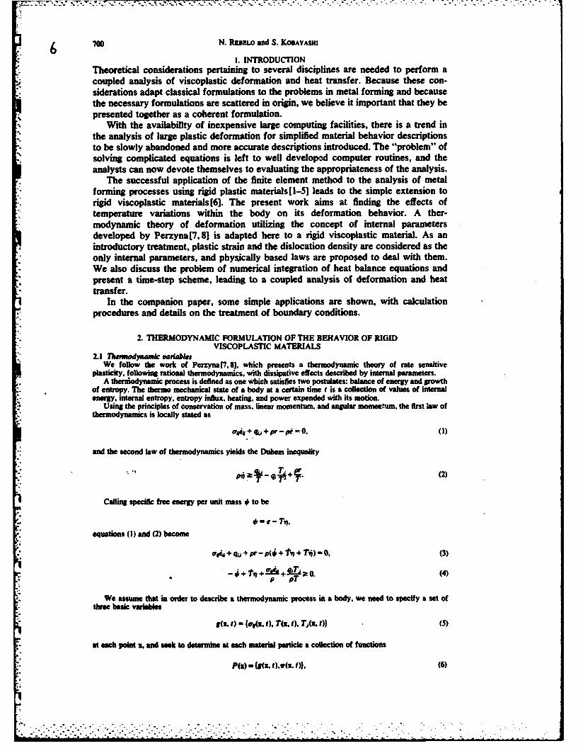
I. INTRODUCTIONTheoretical considerations pertaining to several disciplines are needed to perform acoupled analysis of viscoplastic deformation and heat transfer. Because these con-siderations adapt classical formulations to the problems in metal forming and becausethe necessary formulations are scattered in origin, we believe it important that they bepresented together as a coherent formulation.
With the availability of inexpensive large computing facilities, there is a trend inthe analysis of large plastic deformation for simplified material behavior descriptionsto be slowly abandoned and more accurate descriptions introduced. The "problem" ofsolving complicated equations is left to well developd computer routines, and theanalysts can now devote themselves to evaluating the appropriateness of the analysis.
The successful application of the finite element method to the analysis of metalforming processes using rigid plastic materials[l-5] leads to the simple extension torigid viscoplastic materials[6]. The present work aims at finding the effects oftemperature variations within the body on its deformation behavior. A ther-modynamic theory of deformation utilizing the concept of internal parametersdeveloped by Perzyna[7,8] is adapted here to a rigid viscoplastic material. As anintroductory treatment, plastic strain and the dislocation density are considered as theonly internal parameters, and physically based laws are proposed to deal with them.We also discuss the problem of numerical integration of heat balance equations andpresent a time-step scheme, leading to a coupled analysis of deformation and heattransfer.
In the companion paper, some simple applications are shown, with calculationprocedures and details on the treatment of boundary conditions.
2. THERMODYNAMIC FORMULATION OF THE BEHAVIOR OF RIGIDVISCOPLASTIC MATERIALS
2.1 Thevodyumic variablesWe follow the work of Perzyna [7, 8]. which presents a thermodynamic theory of rate sensitive
plasticity, following rational thermodynamics, with dissipative effects described by internal parameters.A therviodynamic process is defined as one which satisfies two postulates: balance of energy and growth
of entropy. The thermo mechanical state of a body at a certain time t is a collection of values of internalenergy, internal entropy, entropy influx, heating, and power expended with its motion.
Using the principles of conservation of mass, linear momentum, and angular mome*'win, the first law ofthermodynamics is locally stated as
ui44 + qu + pr- p = 0, (I)
and the second law of thermodynamics yields the Duhem inequality
Calling specific free energy per unit mass * to be
e - T'".
equations (I) and (2) become
W44 + qj + pr - p4 +P + T,)= 0. (3)
+T 2(4).- p pa
We assume that in order to describe a thermodynamic process in a body, we need to specify a set ofthree basic variables
g(R. t) - {ef. t), T(Z, ), Tj(z, )} (5)
at each poit z, and seek to determine at each material particle a collection of functions
P(s) - {g(8, ),,r(I. t)), (6)
.2.
.-.7- .

A coupled analysis of viscoplastic deformation 701
where a represents the set of variables
* (x. t) - {Ws, t), ,x, t), q(x, t)1, (7)
satisfying inequality (4).Heat supply r(x. t) and body forces F do not need to be specified, as they can be determined by (3) and
by equilibrium equation
aim+ F = u. (8)
2.2 Constitutive equationsFor the definition of the thermo-mechanical state, two propositions are accepted; (I) the thermo-
mechanical state can be specified by g(x. t) and by its method of preparation. (2) the method of preparingthe actual stress temperature configuration can be determined by one group of internal parameters w(x, t),which, in a ridid, rate sensitive plastic material, describes internal structure changes produced by plasticdeformation.
Accordingly, the thermo-mechanical state of a particle at x at time t is described by the value at t of
k(, t) - {g(x, t) w, 0), (9)
and by the initial value problems given by
*(x, ) W(h(x. t)), (10)
w(x, to) wjx). (1)
It is assumed that constitutive relations determine
r(x, t) = R(h), (12)
with
R { (,q,}.
The Duhem inequality imposes some restrictions on the constitutive relations (12).
Assume that # is a piecewise continuously differentiale function with respect to h(z, t);
=-- t+-At, + A* +A &4 (13)
Then (4) becomes
-(a, ) aT, MO-
4d,_. - * + I-TLao. (1,4)p aw pT
Since we can choose arbitrarily 1, t and &# for a process and still obtain an admissible localthermodynamic process, it must be
--t--0 (15)OT4
M..-, (16)aTA.0, (17)
TA+ -ow At a t0p+-l jut• o (IS)pT p aw
2.3 SpeoWk as to mei fonmng problemsBy usin the concept of internal parameters, virtually any feature of material behavior can be taken care
of, either nacoscoplcafly or microscopicaly. Microscopic behavior includes isotopic or ansotropicworkthrdnins relaxation, creep, etc. and microscopic includes, dislocation density, phase tranformationg inpeie, e.
U 'orMaly, data referri to this kind of treatment are not easily available. Hart et al.(9-11] havedo pad an experimntal propam where an exhaustive number of phenomena are taken into con-
ration to describe the nonastic deformation of metals. This type of data, when fully available, will bean excellent basis for the preset formulation.
, . , . . , .. . . . . . '. . ". ' . . - , - . - . . .. . , - - . .
, . . ., o . . . . .. . ., • . . . . . , . , , • . . , , - , .

702 N. RDnELo and S. KOBAYASHI
For the time being a simple analysis is made, in * ich the only internal parameters considered are theplastic strain tensor and the dislocation density a. These parameters are involved with a measurement ofworkhardening and the change in free energy that external loads produce during deformation in a stablenon- recrystalizing material.
The rate equation (10) corresponding to the plastic strain tensor is simply borrowed from the mechanicalanalysis of rigid viscoplastic deformation(6, 121. We recall that a stress space yield surface expands withthe strain rate from a static yield surface, and that a Mises-like law is obtained, provided we assumeisotropy, isotropic workhardening, and no further dependence on internal parameters.
± 03 - (19)in (19) i is a function of strain, strain rate and temperature, and is the scalar representation of how the
yield surface behaves. In order to express the dependence on strain rate, experimental dat were found to
be adequately fitted by expressions of the form
o (20)
where Y is the static yield stress, and Y, n and -f are functions of strain and temperature.The rate equation (10) corresponding to the dislocation density is written based on physical grounds,
although the values can be accurate only to the order of magnitude. For this reason we use a simplemacroscopic approach, instead of the elaborate physical metallurgy models. Fortunately, as will be seen inthe final form of the heat balance equations, the contribution of these terms is small. We take then
a - Al - Ba -var,
a(to) - 0, (21)
in a simple attempt to say that dislocation density will have both a positive rate component, due to anincrease in plastic deformation (strain hardening), and a negative one. In terms of high temperaturedeformation, this negative component can be due to annihilation occurring from the diffusion-driven climbof dislocations. In such a case, the greater the number of dislocations, the higher the probability ofannihilation.
The constitutive relations (12) are specialized as follows.A hot metalworking process does not usually take very long, and the temperature changes come from
plastic work and losses to the environment. Therefore, an isotropic Fourier law for heat flux, with constantthermal conductivity k, is appropriate
: q, - ki T . (22)
As is done in elastic-plastic theory[ 13-15, we assume the following decomposition
* 0- 10() + 02. a), (23)
and take':r 7, =-!(f dT) dT (24)
where the specific heat (at constant volume) c is assumed constant in the working temperature range.Now the internal parameters can be used to describe the energy which goes into the structure of the
material. Since we neglect elastic deformation, strain energy doesn't apply, and only the energy ofdislocations is involved, as
02 (25)p
From (23), (24) and (16) we have
Jr 7 r LdT)dT+M" (23a)
f r T, (16a)
and the dissipation inequality (18) becomes
qjA+E !PA.*+ ,.rka_ t0 (26)pT p p p
In (26) OT, a O, therefore,
q a! ,Ai- vBa '011T. (26a)
IJ

A coupled analysis of viscoplastic deformatio, 703
This restriction is satisfied with experimentally determined values of v, A and B. In fact, the r.h.s.represents the rate of energy spent in creating new dislocations, and it has been shown experimentally thatthis dislocation energy ranges between S and 15% of the work spent in plastic deformation.
3. LOADING AND BOUNDARY CONDITIONSUsually temperatures, temperature rates and stresses are not specified in a process; instead body forces
and boundary tractions, together with heat supply both internal and through the surface are known. Theequivalence is obtained through equilibrium and energy balance equations.
As closed-form solutions are virtually impossible to obtain in a general problem, numerical ap-proximations are sought. A finite element discretization is a widely used and well-proved method to whichwe will refer, without entering into its details.
Assuming that no body forces and no inertial effects are present, equilibrium equations become, throughthe volume
0rj . (27)
Writing equation (27) in a weak form
f.1 6qu dv = 0. (28)
Applying the divergence theorem to equation (28), we obtain
fobVdadv - f Ti~mi dSF =0, (29)
with imposition of boundary tractions
= avni. (30)
Boundary displacements are imposed in the form of their rates (velocities). By discretizing, using (19).and solving finite element equations, a velocity field is obtained and strain rates and stresses aredetermined.
The energy balance equation (3), considering no external body heat supply, becomes
anwk + k, T. - pct - PAe + PBae--r = 0, (31)
and, in a weak form.
f k, T,ST dv - f pcl"5T dv + f (a,- vA, + pBae-r)ST dv =0. (32)
By using the divergence theorem
f k, TST dv +f pc8T dv-f (a,- vA + Bae ar)STdv -L q.ST ds 0, (33)
where
q. = kT. (34)
is the boundary heat flow.Simple forms of boundary heat flow suffice for the present formulation. Radiation heat flow is expressed
as
V" = O(T" - T;). (34a)
Convection heat flow is expressed as
V - h(T - T,). (34b)
Temperatures also can be directly imposed. Upon discretization and solution of finite element equations,we obtain a temperature field provided we know stresses and strain rates.
Equations (29) and (33) are highly coupled, making a simultaneous solution of their finite elementcounterparts necessary. This process is treated with time dimension analysis.
4. TIME DIMENSIONIn order to describe a deformation process in time, integration of rate equations (19), (21) and (33) must
be performed with respect to time. As far as the strain equation is concerned, the assumption of no inertialeffects requires that for small intervals of time. velocities (and strain rates) change by very small amounts.The strains at time t + At are obtained from their values and rates at time t
= e, + iAt. (35)

/ o 704 N. REDELO and S. KOBAYASHI
Similar treatment is made with respect to updating displacements, using velocities.In standard finite element books. e.g. [16], it can be seen that beat balance equations such as equation
(33), upon finite element discretization are reduced to the form
Ct+ KT = Q. (36)
The theory necessary to integrate these eqtmtions can be found in numerical analysis books[17, 18]. Itsuffices to say that one-step method is used. Convergence of a scheme requires consistency and stability.Consistency is satisfied by an approximation of the type
T,+ = T, + At*[(l - )T, + To, jI
where 0 is a parameter varying between 0 and i.For unconditional stability, , should be greater than 0.5, and a value of 0.75 was chosen. Selection of a
proper value for j is an important factor in the situation where it is desired that the time step be as large aspossible, provided that the increments in strain are compatible with an infinitesimal analysis. In the standardtest problem for checking numerical integration schemes, this value of P gives good accuracy in a widerange of values of At starting at zero.
An implementation of the algorithm above, considering T,,5 , as a primary dependent variable[19l. hasbeen elaborated here in order to include the coupling of the solution of stress equilibrium equations withheat balance, and to include updating of internal parameters.
The sequence of calculations to be performed in one time step At is as follows- (a) assume that theinitial temperature field and dislocation density distribution To and a0 are known; (b) calculate initialvelocity field from equations (29): (c) calculate initial temperature rates To, from equations (36); calculateinitial dislocation density rates 60, from equations (21); (d) calculate
T =- t'T.-
(e) update displacements and strains, (f) use the old velocity field for first anproximate temperaturecalculations
R CTsolve
(+ C) (r ) R for V ;
(g) calculate new velocity field from equations (29); (h) calculate second values for temperatures
solve
(K + t)T= R for T"
use a similar procedure to calculate dislocation density; (i) iterate until convergence; (j) calculate new
temperature rate
and new dislocation density rate.It should be noted that integration of equations (21) follows the same procedure described above, since
equations (21) and (36) are of the same type.
5. CONCLUDING REMARKSIn order to simplify the description of the algorithm for the coupled analysis, the
solution for the velocity fields has not been detailed. The finite element equationsobtained from (29) and (19) are nonlinear, and an iterative scheme based on the Raphsonmethod is used. Such a scheme, as well as convergence criteria, has been described atlength in previous papers [2, 3, 5).
Dislocation density values used are averages for each element. This procedure isjustified by the large uncertainty in data, and by the moderate influence of thesevalues in the rest of the calculations.
We have presented the theoretical background necessary for the solution ofmetalworking problems in which temperature variations as well as a heat transferanalysis are important. The concept of internal parameters, and the way they areimbedded in the solution algorithm, opens good perspectives for better descriptions ofmaterial behavior, and of physical phenomena concurrent with plastic deformation.
, : . . .. . . .

A coupled analysis of viscoplastic deformation 705
Achnwdeipasews-The authors wish to thank the Battelle Columbus Laboratories for the contractS-2933(7128) and the Army Research O~e for the contract DAAG29-79-C-0217 under which the presentwork was possible. They also wish to thank Ms. Katie Triest for editing the manuscript.
REFERENCES1. C. H. Lau and S. Koe*vwu. Now solutions to rigid plastic deformation problems using a matrix method.
1~vn. ASM5, J. RW Ind 9. 315 (1973).2. &S. On0 and S, KosAyAuu. Warkabity of ahminun alloy 7075-T6 in upsetting and roiling. Trans.
ASME. I. Bnv l. I" ftm (1916).3. S, KoSAyAUU ad S, N. SumI. The matrix method for the analysis of metal-forming processes.
Adeaee in Deleuema tOecesting. p. 5 1. Plenum Press, New York (1978).4. S, KoosA=san J. H. lKP4. Dsforuieoi analysis of axisymmetric sheet metal forming processes by
the riplicu baim elemeent method, MAfihws of Shet Mwul Forming (Editors, D. P. Koistmn andN. M. Wan) p. 341. Pboen Piass, Now York (19731).
5. C. C. Cm and S. Ko@AYA=a. Rlpld plastic &Ase elemenat analysis of ring compression. In ApplicationsofM Nmrcall~ehdo WnPrcees. ASME AMD Vol. 29, p. 163, New York (1978).
6. S. 1. On. N. RassLo and S, Ko*AvA=.E Feiie element formulation for the analysis of plasticdeformation of rage sensitive meaterals an metal forming. IUTAM Symposium on Metal FormingPlastiity, p. 273 Tutming (1973).
7. P. PEUZYNA, Thermodynamic theory ot viscoplesticity. Advances in Applied Mechanics. Vol. 11, p. 313,* (1971).
S. P. PERZvtA and A. SAwczuv, Problem of theemoplasticlty. In Nucla Engineering and Design, Vol.24, p. 1 (1973).
9. E. W. HART, Constitutive relations for the nonelastic deformation of metals, Trans. ASME. I. Engr.Met. Tech. Vol. 98. p. 193 (1976).
10. E. W. HmaR. A phenomuoogcl her for plastic deformation of polycrystalline metals. Acta Met.1& 5"9(1970).
1I. E. W. HAirT. C. Y. Li. H. YAMADA and (G. L. Wow., Phenomenological theory: A guide to constitutiverelations and fundamental deformation properties. Constitutive Equation in Plasticity (Edited by A. S.Argon). M.I.T. Press, Cambridge, Mass. (1975).
12. P. PUUZYA, Fundamental problems in viscoplasticity, Adv. Appi. Mech. 9, 243 (1966).13. J. T. ODNg. D. R. IHANDARI. G. YAGAwA and T. J. CHUNG, A new approach to the finite element
formulation and solution of a class of problems in coupled thermoelastoviscoplasticity of crystallinesolids. Nuci. Engnig Design, 24,.420 (1973).
14. W. S. TsENG, Ph.D. Thesis, University of California, Berkeley (1971).15. J. M. KELLY, Non-linear constitutive relations for plane shock propagation in viscoplastic solids. Arch.
MAfch. Stos. 1, 22 (1970).16. 0. C. ZmNmgwic, The Finite Elemet Method, 3rd Ed,. McGraw-Hill. New York (1977).17. (G. DANLQuisT and A. Dhoacx Numerical Methods. Prentice-Hall, New Jersey (1974).18. A. RAismo, A first course in numerical analysis. McGraw-Hill, New York (W96).19. R. L. TAmoRt, Seminars on Advanced Topics in Finite Elements. University of California, Berkeley
(1979).

12 IaLjhAecksc& vol 2. pp 707-715. P-sum Pmu LA&.. 1W.O prlod ip Ca WkiW
#42.A COUPLED ANALYSIS OF VISCOPLASTICDEFORMATION AND HEAT TRANSFER-Il
APPLICATIONS
N. P BELO and S. KoBAyAsHIDepartment of Mechanical Engineering, University of California, Berkeley, CA 94720, U.S.A.
(Received 22 Febiary 1960)
Summary-The finite element formulations for coupled analysis of deformation and heattransfer are applied to the problems of solid cylinder compression and ring compression. Thetemperature distributions in solid cylinder compression are compared with experimental data,and the computed results of ring compression of aluminum at elevated temperature arecompared with experimental observations as well as with calculated results not including thetemperature eflects. It is demonstrated that the coupled analysis accurately simulates theseprocesses.
NOTATIONY static yield stressi strain rate
•y. n material parametersYTo static yield stress at r e temperature TQ material parameterk Bolt-man constantT absolute temperatureC he capacity matrix9 heat conduction matrixQ heat flux -ectorT vector of nodal point temperaturest vector of nodal point temperature ratesN interpolation function
a rate of plastic workvAi- ,,Ba e- rate of change of dislocation energy
A. B material constantso dislocation densityD energy for self diffusionv energy per unit length of dislocation
T, environment temperature, surface temperature
T, die temperatureT. workpiece temperaturea Boltzman constante radiation coefficienth heat convection coefficient
/A heat transfer coefficient from lubricantq, surface heat generation rate due to frictionI friction force
v, relative velocity between the die and the workpieceH workpiece height in -mk. heat conductivity-workpieceA, heat soductivity-diec. heat capacity-workpiecec, heat capacity-diep mass densityn number of strokes per minute (press)S stroke of the pressW distance from lower position
1. INTRODUCTIONThe theory necessary for developing computer simulations of transient viscoplasticmetal deformation coupled with a heat transfer analysis has been presented in thecompanion paper( 1).
707

/13 708 N. RUSLo and S. KoBAYASIUI-
When deformation takes place at high temperatures, material properties cam varyconsiderably with temperature. During a metalworking process, large noogmeitin deformation and consequently in heat generation, iinudly occur. Moreover. especiallyif the dies are at a considerably lower temperature than the workpiece, the heat losses byconduction to the dies and by radiation and convection to the environment contribute tothe existence of severe temperature gradients. Thus including temperature effects in theanalysis of metal forming problems is very important.
Furthermore, at elevated temperatures plastic deformation can induce phasetransformations and alterations in grain structures which in turn will modify the flowresistance of the material as well as other mechanical properties. Inchading thesemetallurgical effects in the process analysis contributes signillcanly to the under-standing of material behavior under plastic deformation.
The importance of temperature calculations during a metal forming process hasbeen recognized for a long time. Until recently the majority of the work has beenbased on procedures that uncouple the problem of heat transfer from the metaldeformation problem.
Several i esearch workers have used the approach of determining the low charac-teristics of the problem either experimentally or by calculations, and then of usinthese calculation for the calculation of heat generation. Among these is the work ofJohnson and Kudo(21 on extrusion, and Tay, Stevenson and Dens(31 on machining.Another approach uses Bishop's [4] numerical method, in which heat gneration andtransportation is considered to occur instantaneously for each time step, with con-duction taking place during the time step. The new temperature distribution is used tocalculate flow characteristics, which in turn will originate the instantaneous heatgeneration and transportation for the next step. This approach is represented by thework of Altan and Kobayashi[51 on extrusion, Lahoti and Altan[61 on compressionand torsion, and Nagpal, Lahoti and Altan[7) on forging. Usually the temperaturecalculations are done by finite differences, or by finite elements, and the upper boundtechnique is the most common for determining flow patterns, if not experimental.
As far as we know, a paper by Oden, Bhandary, Yagawa and Chung[8] presents thefirst coupled analysis of deformation and heat transfer, although the application is to a3-dimensional rectangular bar, which was constrained on one direction and heated at acorner. The formulation is for elastoviscoplastic materials, and uses the same rationalthermodynamics background we have used in the present work.
Zienkiewicz, Onate and Heinrich[9 have made a coupled thermal analysis inextrusion. Because it is a steady state situation, the heat balance equations andequilibrium equations, using rate sensitive materials, are solved simultaneously.Previously Zienkiewicz, Jain and Onate[l0 had proposed to solve the same problemby separating the equations, and iterating the results between the two sets of solutions.
The purpose of this paper is to show the results of calculations by applying theformulation developed in (1) to metal forming problems, which demonstrate tem-perature effects clearly, and to show the potential for further refinements. A briefdiscussion of the basic finite element equations is presented, in which some details ofthe treatment of boundary conditions crucial for the algorithm are given.
The compression of a solid cylinder of AISI 1015 is analyzed and compared withexperimental data obtained by Pohl[I I]. Also, the computed results of the forging ofan aluminum 1100 ring at 400WC are compared with the one studied in [71 as wed as withcalculations hot including the temperature effects[12].
2. BASIC EQUATIONSThe finite element equations resulting from discretizing weak forms of equilibrium equations and hat
balance equations are described in the Ilterature. We discuss here only the details that are important in theimplementation of the algorthm presented in the compenion paper.
As far as equilibrium equation are concerned, the only mod&ation of the analysis of Oh, Rebelo andKobayashi[12 is the temperature dependence of the low stress. Recall that experimental date on lowstress has been fitted by the expression of the form
-Y (I)

j4.A coupled anelysis of viscepilastic didfrmo-1 709 M
. and th Y. n. - as hctins of stmin and temperature. For the range of temperature -iriations in the"+ intel fe l prblems, amd wIthi. the accuracy of data avalable. equaio (1) can be c !ssed as
Y'- Vr.y f I u t+ (2)
Yy Y xb and % functions of strai.The fictio faclor is deflnd as the ranio bw the frictioal shear stms and the rate aWd1mp m 1 1a 1 yd - a- s.For host balance equations. we mcal again that there m of the form (see E.G.[131);
Ct- Q. (3)
Whire the hea lux vector Q has several components (e iD;
f (&i - vAi + s'Bo e'a*')N d V + . e (T.4 - T')N dS,
+ f .(T - T,)N dS, + f lh.(T - TW )Nd (4)
+fJ*NdS.
The Amt component is the contribution of t- ne heat generated inside the deforming body. the secondone the contribution of the heat radiated into the body. and the third. the contribution of the heattranserred by convection. The fourth term represents the contribotio of the beat transferred betweenworkpiece m die through ther interface twith or without lubricant). and the last term is the contribution of
*the heat generated by friction between die and workpiece.The folowing remarks pertin to the implementation of the algorithm previously described.We tast the workpiece mde die suprately. In this way, we greatly reduce the number of equation
to be solved simultaneously, which in turn reduces the cost of the tolution. In the die there is no internalheat generation and no deformation calculations re necessary (rigid dies). Because of the beat trander atthe interface, the die and the workpiece equations contain temperatures of each other, and the solution isfound iteratively. For two reason, this brings no increase in cost: first, iterations with respect to thevelocity have to be done anyway; and second, matrices do not have to be recalculated at each iteration.as only the beat-flux vector changes.
In a numerical testing of heat tnsfer calculations, it was found that lubricant beat transfer coefficientsat least one order of magnitude higher than the real ones were necssary to produce instability.
The heat generated through frictitn, and calculated by
was evenly distibuted between the die and the workpiece.The die had to be semeshed at each time step, in order to make the nodes at the interface match. Again,
numerical testings were made with similar mesh changes in a heat trander problem whose exact solution isknown, and the error in temperatures so introduced was very small.
The temperature values used in the internal heat generation and radiation terms of heat flux are at alltimes those values from the previous iterations.
Dislocation density calcultions, made only in the workpiece, represent a minute fraction of operations,because no coupling was considered from element to element. For each element the scalar version of thetime integration scheme described for temperatures was used.
3. COMPRESSION OF A CYL/NDER OF AISI 1015 AT ROOM TEMPERATUREPohldll] conducted temperature measurements in order to test his uncoupled analysis, in which
approximate stream functions were used for the deformation, and finite differences for the heat balance. Asolid cylinder of a carbon steel AISI 1015 was compressed between flat dies at room temperature.Thermocouples were inserted in the cylinder at different locations. Upon deformation, their readingsindicated the temperature increases due to the heat generated, but no assessment was made with respect tothe accuracy obtained in such measurements. Nevertheless, this is one of few cases in the literature whereactual temperature distriluions wer reported.
Fi. I shows the dimensions and locations of measuring points.Although the values of some parameters must be "guessed" in computation, the results of our analysis
are compared with those measurements.The conditions used in the computation are as follows.The deformation took place at initial room temperature, up to a height reduction of 113. The finite element
grid was composed of 132 four node quadilateral elements in the wrkpiece. and 119 in the die. Because ofsymmetry, only one fourth of the cylinder needed to be analyzed. The friction factor was taken as 065.
In order to simulate a mechanical press, the die velocity was changed at each time step according to the
v - 12 * V(H-20) mms.
Each step corresponded to 1% in beight reduction, which was equivalent to time steps of up to 0.03 se.In this case the flow stress was taken independently of strain rate and temperature. This is justifiable for
MI V L Me. ii. -D

IV
710 N. RN w and S. KoBAYAS 15
454 . 0
1126
122I 130
20 10mM
INITIAL LOCATIONPOINT % mm ZoM
45 00 9.55To 0.0 5.45122 0.0 0.049 4.0 9.55126 4.0 0.053 IO 9.556 6.0 0.0
FRo. I. Specimen dimensions. Die dimensions. Locations of temperature measurements(I I.
steel being deformed at room temperature. The flow stress values, as given by Pohl, were
a - 27 Nmm e < 0.2512S-. 722, *ec Nmm e 0.02512 .
The heat transfer characteristics, other than the thermal conductivity and heat capacity of AISI 1015measured by Pohl. are taken from handbooks;
k,- 36 NIs *Kpc - 3.77 N/mm2 4K
k, - 19 Nis "Kpc, = 3.77 Nlmm2 *Kow- 8 10'" Nlmms (iCY
h - 0.00295 Nis mm "KI,, -4NISmm*K.
The dimensions of the die are such that at the outside boundaries a constant temperature is imposed.The material was given an initial dislocation density of l0'/mm'. and constants A. B. r and D were
chosen in such a way that practically no annihilation occurs (room temperature), and the density gowswith strain to an order of 10/mm at a strain of about 309
A 1253. tOImmB = 15* 1IsS
Dlk =170000Kv 317.10-" N mm/mm.
Fig. 2 shows the initial finite element layout, and Fig, 3 shows how it deformed after 113 reduction inheght. The barreling and the nearly sticking situation along the interface should be noted.
In Fg. 4 the effective strain distribution is shown, which points out the nonuniformity in deformation.The most deformed zone is the outside corner, and shear band formation is clearly seen. As expected, thezone under the die shows little deformation.
Temperature contours in both workpiece and die are presented in Fig. S. In the workpiece thetemperature disibution has a similar pattern to that of effective strain distribution. Sinc the initialtemperaures were the same for die and workpiece, and equal to room temperature, internal heat generationis clearly the prevailing factor in modifying temperatures. The temperature distrbution in the die showswell that the most deformed zone was the largest source of heat.
The temperature values measured by PohI are compared with the calculated values in ils. 6-8.The agreements are excellent for the inner points, as seen in Figs. 6 and 7. For the most outer points.
however, the computed results indicate that the temperature differeace for the three points is minor, whileexperiments show more difference. Nevertheless, this difference does not seem to negate the analysistechnique. as the heat conduction part of the progam has been tested with accurate results and theaccuracy of the finite element deformation analysis has been well established.
The discrepancies seen in Fig. 8 can be attributed to possible inappropriate material constants andexperimental inaccuracies.

*A coupled analysis of viscoplastic deformation-Il 711 16
35
30
25
20 I
1 5
S
0 S 1 0 15S 20 25m
FIG. 2. Finit element layout for AlSI 1015 steel cylinder compression.
* mm3 5
30
25
2 0
1 0
0
0 5 1 0 1 5 20 25Srm
Fjo. 3. Distorted Vri pattern after 113 reduction in heigt.
7

712 N. Maew and S. KOBAYASI/
.1
Fla. 4. FIG. S.
Pta. 4. Effective strain distribuzion after 1/3 reduction in heilght.
ft. S. Teinpersilure distr~iutlion aftr 113 reduction in heogt.
AT OK80
POINT 45 78 122
60SYMflOL s o + +.
60-
20-
00
00 0.1 0.2 0.3 04 05 06 times
F0a. 6. COEPulm Of Umgrature lsrbiadon betwe e woy (-)s experiments (x, 0, 4)
WTK60
POINT 49 126SYMNIL
60-
20 'H
0 0.1 0.2 0.3 04 05 06time s
Pta. 7. Comparison of temperature dlutribudoe between theory (-)an expeiment (x.4)

, 8A coupled analysis of viscoplasbc deformation-lI 713 /
'. AT *K.. 80 I ! I I
-POINT 53 86 130
6 0 SYMBOL x ++
40
20
00 goo I - I I
01 0.2 0.2 0.4 0.5 06 time s
- F. 8. Comparison of temperature distribution between theory (-) und experiment (X, 0, +).
4. COMPRESSION OF A RING OF ALUMINUM 1100 AT HIGH TEMPERATURE* Complete finite element solutions for ring compression of rigd plastic materials have been obtained by
Chen and Kobayashi[14. In [12) they were extended to rate-sensitive materials. The purpose of analyzingthe problem with temperature effects is twofold; to compare calculations with some experimentalmeasurements of Nagpui, Lahoti and Altan[7J and to compare them with our previous results withouttemperature effects. The success of the analysis makes it possible to extend the ring compression test to
* quantitative lubricant evaluation in the hot forming range.The rings tested have a o.d. i.d.: height ratio of 6:3: 2, and an outer diameter of 54 nun.As both dies and workpiece had their surfaces cleaned, and no lubricant was used, the friction factor
' was taken as 1,0. The dies were initially at room temperature, and the rings were heated to 42"C (UWF).Total reduction in height was 509. and the calculations were performed in steps of 1% deformation
each. T. equivalent time steps did not exceed 0.003 sec. Assuming symmetry, one quarter of the ring wasanalyzed and 104 4-node quadrilateral elements were placed in the ring and 150 in the die. Fig. 9 showsthe initial grid layout as well as the dimensions.
In order to simulate a mechanical press, the instantaneous velocities of the die were obtained from theexpression [ 15);
v 0-1* n * V(S* W- W2 ) mm/s'I - 9S- 254mm
W - 9 mm initially.
Flow stress expressions for Aluminum 1100 were derived from experimental data of Lindholm[16 and* Altan and Boulger[17]. The expressions in Table I correspond to a reference temperature of 400C to which
the following factors in equation (2) were applied
i • ° r" - 3".S,
QOk "852"6855"K.
TAKLE I. STRusvmsrw smrirN-ATIu litaoe s oF Al 1100 At:.W USE IN) CALU.CLATIONS
e 005 0.10 0.15 025 0.50 0.70
. 0.346 0.226 0.200 0.419 0-507 0.502.' 7.908 3.936 4.162 4.228 5060 4.509V 2 + 10.86f - 29.84#2 3+ 2.765(,-0.15) 3.4
+ 12.7e' -590.-0-15F_+ 13.866(e -0.15?
20
DI
0 6 1 2 16 2 4 3 0 36 42 468mm
fto.9. Initial mosh for Al 1100 ring compression.
,

714 N. Ru .o and S. KOAYASNI
The heat transfer characteristics were taken from standard handbooks.
k. - 242 N/s Kpc, - 2"425 N/mm' OK
k, - 19 N/s "Kpc d .= 3-77 Nlmm *Kor - 85 * 10' 3 N/mm s'K'h - 0007 N/s mm K, " 35 N/s -an 'K.
As Fig. 9 shows, the outer boundaries of the die are sufficiently far from the interface so that a constant*temperature is imposed on them.* The dislocation data utilized were prepared under two basic assumptions. First. if there were no
anihillation, dislocation density would pow from. say. 1O1Immz in the annealed state to IP/mm' at aneffective strain of 50%. Second. because of annihilation at high temperatures and in a relatively fastprocess, dislocation density will not gow above lOh/mml . The values used are
A -2. 10I1mm"B - II * to1sDk -17000"K
-I05. 10" N rm/mm.
In deformation calculations an average of 12 iterations were needed for convergnce. and up to 3 morefor temperatum . Whenever a node on the surface touched the die, convergence was much much slowerand up to 30 iterations were then needed.
Fig. 10 comperes the decrease in inner diameter vs reduction in height obtained in the presentcalculations with the experimental point of Nagpal et aL and with the previous solutions not includingtemperature elffects. When the effect of temperature is included, the effect of chilling by the dies causesrelatively small sliding alone the interface and results in more decrease in inner diameter than the casewithout temperature effect.
Fi. II shows the rin proffies after 48,5% reduction. The ageement is excellent between computedand experimal proliles.
Grid distortism. i the low of material after 20 and 50% reduction. are presented in Figs. 12(a)and 13(a). The matral nee is distincivey tracable, and the large amounts of folding are evident. Theirequivalent elective strain distributions. clearly showing the nonuniform deformation, am given in Figs.14(a) and l5(a). The most deformed areas are the original corners in contact with the die, and the leastdeformng reon are noticea ma the neutr axis. A comparison with equivalen figures (12(b)-15(b))for the t11ei n calcultions in similar conditions indicates a more severe distortion in thetemeratr dependet can. and demonstates how the die-chilng elect cocentrates the deformation onthe equaorial regions, which ae the homst and last resistant to low.
A charactaetic behavior of calculated dislocation densies is that they nces sharply during the Girst5% of deformation, to valui, from 106Imm up to 5 * O1071am. At this point the elements at highertemperatures begin to have negative rats, while the ones nar the die keep increasing their densities. At25% deformation the hiW nt valus of 1.2, t091mm is reched, in the upper right corner element. By dottime the pea maor0y of elements have densities betwee I and 3, lOMam, although some ae increasingand others decreasin, When 46% defwaio isa reached, all eements start to have negadve rates ofdislocation density. This mean that the density values reached wre high cano to induce s"n anihiation.eve in he codme zoea wear the die. The averWe values at this staep me in the lO'/mmorderof magnitude forthe hoter zons. and the lUWmail order of magnitude for the colder zons.
60 1 1 1, I-mel D AMIC 2
sSO - ISOTHgRMAL2-me I DYN&MI
TEMP. IFF ECTS40 - o-EXPENIMENT
30 -
S20-
10
0 0 20 30 40 50 60
REOUCTION %
Pa. tO. Cha or ring inner diameter as functioe of reduction in heigh.

% . . . . . . . . . .-. - -' ..-
2 A coupled analysis of viscoplastic deformaion-lI 715 2)I mal DYNAMIC ISOTHERMAL
2 EXPERIMENTALmm 3 ml DYNAMIC TEMP EFFECTS
10 20 30 3 40 mm
FIG. 11. Deformed ring profiles.
FIG. 12. Grid distortions of Al 1100 ring at 2% reduction in height (a) with temperature effectand (b) without temperature effect.
,.". (b)
FIG. 13. Grid distortions of Al 1100 ring at 500 reduction in height (a) with temperatureeffect and (b) without temperature effect.
I
SI ....04
i" I
I
I0.26 0t..
,o
PfO. 14. Strali distributions of AI 1100 ring at 20% reduction in height (a) with temperatureeffect and (b) without temperature effect.

2.- 716 N. RUELO and S. KOAYASH 21
03I.
GasaI I 0.88 308
JJ 2 4 6 6 40 1zS9
66
FIG. 15. Strain distribution of Al 1100 ring at 50% reduction in height (a) with temperature effectand (b) without temperature effect.
We chose the material constants for the dislocation density calculations, having in mind that in overall
defornation the energy spent with the creation of dislocations is around 10% of the total deformationenergy. The results discussed above show that the former energy is mostly spent in the early stages ofdeformation, and that towards the end, annihilation is helping plastic work to supply heat generationthroughout the body.
In Fgs. 16 and 17 temperature contours in both ring and die are presented. The temperature field is
dominated by the heat Sow from the workpiece to the die, and only near the equator temperatures riseslightly. Temperature differences across the workpiece die interface decrease from 407 K initially, toaround 220 K at the end of deformation.
An appraial of inluence of parameters in the temperature calculations was done by roughly calculatingheat fluxes in I radian section for a typical step of deformation, and comparing them to heat generation;
radiated heat - 350 Nnmlsconvected heat - 500 Nmm/sbeat lost to die - 650000 Noun/shet generated - 1000000 Nmms
this indicates that heat generation and conduction to the die govern the whole heat balance prou-ss.In Fig. 18 the load displacement curve is compared to the previously calculated one not including
temperature effects. During the initial stages of deformation the values are similar, due to the fact that in
308 'IC
FG. 16. Temperature contours at 20% reduction in height in Al 1100 ring compression.
325
445 635
tI o
Fto. 17. Temperature contours at 50M reduction in height in Al 1100 ring compression.

• A coupled analysis of viscoplastic deformation--l 717 22
DOSPLACEMENTimm0 1.8 3.5 5.4 72 9SI I I I I I
REDUCTION %0 90 20 30 40 50
260 1 1 1 1 1
o 2
-200
2lo. - -,- -I-ma I DYNAMIC -
- ISOTHERMAL -
2-m 1 DYNAICTEMP EFFECTS -0- I DYNAI I
0 4.46 9.50 15.57 23.11 38.72
FtG. 18. Load displacement curves for Al 1100 ring compression.
the temperature independent calculations the flow stress used referred to a temperature similar to the initialone in the temperature dependent case. As deformation proceeds, the zones near the die cool down and theequatorial zones heat up. Since deformation occurs mainly in the latter, the lower flow stress here induces alower total load necessary for deformation.
The decrease in load towards the end is a result of the rapid decrease in velocity of the die, and thesubsequent strain rate effects.
5. CONCLUDING REMARKS
The capabilities of a coupled thermoviscoplastic analysis of non-steady-state metalforming processes have been demonstrated in this paper. The finite element analysisof deformation and heat transfer is a significant extension to the analysis of warm andhot forming processes. It produces accurate simulations of the processes and providesinsight into the governing parameters in the process.
A higher 'level of sophistication infthe analysis is invariably associated with ahigher level of sophistication in the input data necessary. At this stage much work isstill needed in order to utilize all the capabilities of the method. It is hoped that in thefuture the important internal parameters will be screened from the superfluous, andprograms to quantify their importance will be set.
Ackneowedg-ment-The authors wish to thank the Battelle Columbus Laboratories for the contract S-2935(7128) and the Army Research Office for the contract DAAG29-79-C-0217 under which the present workwas possible. They also wish to thank Mt Katie Triest for editing the manuscript.
REFERENCES1. N. RunLo and S. KoAYAsmI, A coupled analysis of viscoplastic deformation and heat transfer-I.
Theoretical consideratiom. Int. . Mec&. ScL 22,11 (1960).2. W. JOHNSON and H. Kuvo, The use of upper-bound solutions for the determination of temperature
dist tions in fast hot rolling and axisymmetric extrusion processes. J. Mech. Sci. 1, 175 (1960).3. A. TAY. M. G. STavmsow and G. V. DAvis, Using the finite element method to determine
ture distributions in orthogonal machining. Proc. Just. Mech. Engineers IU(55/74), 627 (1974).4. J. .W. Boo, An approximate method for determining the temperatures reached in steady-state
motion prolems of plane plasti sftin. Q. A. Mock. Appl. Math. 9, 239 (1956).5. T. ALTAN and S. KomAYAm.I A numerical method for estimating the temperature distributions in
extrsin tlrough conical din. J. E Indust. Trans. ASME 90, 107 (1%8).- 6. 0. LAm and T. ALTAN, P of temperature distributions in axisymmetric compression and
torsion. J. EmM Materials Technol. Trans. ASME, 97, 113 (1975).I-"
' fr.4nm ,m., - s.,==...-.. . .. . .

718 N. Ram.o and S. KOBAYASHI 23
7. V. NAGPAL. G. D. LAHOTI and T. ALTAN, A numerical method for simultaneous prediction of metal flowand temperatures in upset forging of rings. ASME Paper No. 77-WA/PROD-35 (1977).
8. J. T. ODEN, D. R. BHANDARI, G. YAGAWA and T. J. CHUNG, A new approach to the finite elementformulation and solution of a class of problems in coupled thermoelastovisco-plasticity of crystallinesolids. Nuc. Engng Des. U, 420 (1973).
9. 0. C. ZIENKIEWiCZ, E. ONATE and J. C. HEINRICH. Plastic flow in metal forming-. Coupled thermalbehaviour in extrusion-l. Thin sheet forming. AppI. Namer. Meth. Forming Proc. ASMEAMD 28(1978).
10. 0. C. ZIENKIEWICZ. P. C. JAIN and E. ONATE, Flow of solids during forming and extrusion: Some aspects ofI numerical solutions. Int. J. Sal. Struct. 14, 15 (1978).II. W. POHL, A methof for approximate calculation of heat generation and transfer in cold upsetting of
metals. Doctoral Dissertation, University of Stuttgart (1972).12. S. 1. OH. N. REBELO and S. KOBAYASHI. Finite element formulation for the analysis of plastic
deformation of rate sensitive materials in metal forming. JUTAM Symposium on Metal FormingPlasticity, p. 273. Tutzing (1978).
13. 0. C. ZIENKIVEWICZ, The Finite Element Method. 3rd. Edn. McGraw-Hill, New York (1977).14. C. C. CHEN and S. KOBAYASHI. Rigid-plastic finite element analysis of ring compression. Applications
! : of numerical Methods to Forming Processes, ASME, AMD 28. 163 (1978).15. T. ALTAN. Forging equipment, materials and practices. Metals and Ceramics Information Center,
Battelle Columbus Laboratories (1973).16. U. S. LINDHOLM. Experiments in dynamic plasticity. Symposium on Mechanical Behaviour of Mateials
Under Dynamic Loads. San Antonio, Texas (1968).17. T. ALTAN and F. W. BOULGER, Flow stress of metals and its application in metal forming analysis. J.
Engng Indust. 95, 1009 (1973).

THE AMEICAN SOCIETY OF MECHANICAL ENGINEERS 82-Prod-4348 . 47 St, Now York, N.Y. 10017
The Society shell not be responsible for statements or opinlons advanced In papers or Indiscussion at meetings of the Society or of Its Divisions or Sections. or printed in itspublioations. Discussion is printed only it the paper is publshed in an ASME Journal.s for general publication upon presentation. Full credit should be given to ASMF.
the Techlnical Division, and the suthor(i). Pew We avaliab~l from ASME fr nine montheafter the meeting.
h Pi nted In USA.
# #3. '
An Investigation of the ShellNosing Process by the Finite-
Ming-Ching Tang Element Method. Part 1: Nosing"M Sig ang Josalf at Room Temperature (Cold
bShiroKoayashi Nosing)Professor,
Department of Mechanical Engineering,University of California,
Berkeley, Calif. The metal-forming process of shell nosing at room temperature was analyzed by theFellow ASME finite-element method. The strain-rate effects on materials properties were included
in the analysis. In cold nosing simulations; the nine-node quadrilateral elementswith quadratic velocity distribution were used for the workpiece. The treatment of amoving boundary in the analysis of nosing is discussed and successfully im-plemented in the finite-element program. FEM simulations of 105-mm dia. shells ofAISI 1018 steel and aluminum 2024 were performed and solutions were obtained interms of load-displacement curves, thickness distribution, elongation, and straindistributions. Comparisons with experimental data show very good agreement.
Introduction
Shell nosing refers to the process of forming an ogive noseat the end of a tubular part by pressing the tube into a suitablyformed die (Fig. 1). The flow of metal in nosing is verycomplex and only a slight variatior in friction or temperatureconditions may result in a misformed shell due to impropermetal *flow. Understanding the deformation mechanics of a -metal-forming process is an essential and important steptowards the control of metal flow, and, subsequently, thedesign of the forming process. Experimental characterizationsof process parameters involve trial and error, and it is dif-
L ficult to separate the influence of individual parameters uponeach other. It is desirable and necessary to use an inexpensiveanalytical simulation method in order to improve industrialproductivity.
Successful efforts have been carried out by Kobayashi andco-workers (1-41 using the finite-element method in analyzingvarious metal-working processes, such as compression,heading, piercing, and extrusion. The objective of the presentinvestigation is to develop the finite-element simulationtechnique, including flow stress dependence on strain rates,for the shell nosing process.
The flow of metal in the nosing process is affected by thecharacteristics of the lubricant and the speed of the nosingoperation. If the lubrication is not sufficient and if the nosingprocess is slow, the lubricant is squeezed out and the friction
Contributed by the Production Engineering Division for presentation at theDesign and Production Engineering Technical Conference, Washington, D.C..September 12-1S, 19182 of THa AlalwcA Soctarv or MaCtm:ICAL EowoFas-s.Manuscript received by the Production Engineering Division February 8, 1982.Paper No. 82-Prod-14.
Copies will be available until June 1983. FIg.1 SheII nollng pmeeee (ree' ietanie 6,D
Discussion on this paper will be accepted at ASME Headquarters until November 22, 1982

between shell and die tends to shorten the shell. On the other of the nodal point velocity vector v and the element Lagrangehand, if the lubrication is good and if the nosing proceeds multiplier X, the system of equations is obtained in the formrapidly, the lubricant is squeezed out to a lesser extent. ofTherefore, the friction is reduced and the shell is lengthened. f(v,)= (3)
Small caliber shells (up to 105 mm) can be cold nosed, whilelarger shells (155 mm and up) are hot nosed. In cold nosing, Equations (3) are nonlinear in v and linear in X,. To solve thesethe entire shell is initially maintained at a constant ten- nonlinear equations, the Newton-Raphson iterative methodperature and the flow stress is uniform. The deformation was used. Expanding equations (3) into Taylor's series andwork-hardens the shell material nonuniformly, and the maintaining only the first two terms,resistance to further deformation by various parts of the shell aMis unequal. The elastic spring back is very small compared to f(vnA)0 (vnX)Av n O (4)
* plastic strain; therefore, the dies are given the shape of therough-finished nose. The slight elastic back spring is removed which results in the system of equation linear in av and ). Inin the process of finish turning, equation (4), v, represents the input values from the previous
In 1943 Nadai [5] conducted, for the ASME Special solution and Av. represents the correction values obtainedResearch Committee on Forging of Steel Shells, an extensive from the present iteration. After each iteration, the values oftheoretical investigation on the forces required in nosing of v are updated as v,, fI v. + aAv, where a is a decelerationshells. This work is basically an extension of the theory of coefficient. For solution convergence, two measures, namely,curved shells to cover cases in which the metal is in a plastic the error norm of the velocities and the norm of the residualstate of equilibrium. The approximation is based upon equation (3), are used as criteria.constant coefficient of friction and ignores variations in the The constitutive equation (2) becomes undetermined at zeroflow stress of the shell material. Onat and Prager [6] extended strain rate. Whenever some regions in a nonuniformNadai's work to include the changes in the shell wall thickness deformation process become rigid, the system of equationsdue to the nosing operation. They investigated the influence becomes very ill conditioned. To avoid this, a strain rateof these changes on' the stresses in nosing. Cruden and offset lo is introduced such that the stress drops linearly toThompson (71 conducted an experimental study of the nosing zero when the strain state is below l0. This .Qf.fet value isprocess to establish the limitations of the process and to assess chosen only for numerical reasons. Values of two orders of
-the effects of the various process parameters. Recently, the magnitude smaller than an average sirain rate in the defor-metal flow in nosing of shells was analyzed, using Hill's mation have given successful results [11].general method of analysis, by Lahoti and Altan [8].
In the present study of cold nosing operation, the rigid-viscoplastic finite-element method is used for the analysis,with reference to the effects of friction. Simulation of 105-mm shell nosing for AISI 1018 steel is performed, andsolutions are compared with available experimental data from 0 ,L..Battelle Columbus Laboratories [91. The experiments of shell O - 1'..
nosing of aluminum alloy 2024 were conducted and an ex- 0tensive comparison was made between the computersimulation and experiments. ' ,'0 . .
Finite-Element Method
General theories about the finite-element method have beenwell described in many books. Therefore, only a brief F 2 mii systm mdlhumyondllondescription of the method that is necessary for the discussionof the features involved is given here. Detail formulations andcomputer programs for the analysis can be found in reference[101. 1
For an incompressible, rigid-viscoplastic material, thevariational formulation in boundary value problems is givenby
a1 6e,1dV- SF Fj8,dSF + biidV
In equation (1), v is the deviator stress, iu is the strain'rate,Fj is the traction prescribed over the surface SF, uj is the R
velocity, and X~ is the Lagrange multiplier.Constitutive equations for viscoplastic materials are ex-
pressed by
2 .(2)
where a is the effective stress which is a function of strain andstrain rate, and t is the effective strain rate.
Discretization of equation (1) is performed by using nine-node isoparametric elements for the axisymmetric defor-mation problem. Applying the arbitrariness of the variations F9. 3 Confluretlon ofsl durbig nosng
2 Tmnaeotions of the ASME

Tabe I Dimenuion of 105-mam sbell I ICN Ibt
- THEORYOutside diameter at the nose base 108 mm 10.Radius of curvature of the nose ogive 650 nun
* Initial wall thickness of the preform 12 nun 200Axial length of the nose portion lsomm /Distance of the ogive center from nose base 23 nun
15C1O. IS
Computational Procedur 0e 4In applying the finite-element method to shell nosing, some 0,o
thought should be given to the implementation of boundary x /conditions. Figure 2 shows the boundary conditions and the 4mesh that was used in the calculations. Once the nosingprocess begins, the top portion of the tube enters the die zone.The boundary conditions in the contact region are stated not 2 /only by prescribing tractions and incremental displacements,but by their ratios. The radial and axial velocities of thematerial nodes in the contact region are not independent, and 3 4 in.they are related to each other through a mathematical ex- -31 4 ! I in.
pression for the geometrical requirement that they must be 0 40 so 12omnactually on the surface of the die. The expression is DIE PENETRATION
FIBF 4 coIn"8 fr old noaft of AMI 1018 Mol(ro+a) 2 +(zo+b)2 -(ro+Ar+a) 2 +(zo+Az+b)2 =R2 . ($) WIrg
where ro, zo are radial and axial positions of the node at thepresent configuration at time to, and Ar, Az are the increments ' I
of radial and axial displacements. R is the radius of curvature - TNEORYof the nose ogive. See Fig. 3. 0 EXPERIENTU
Rewriting Ar and Az in terms of velocities u, and u, as Ar - at - ,ou,At and Az - u,A1, and linearizing, equation (5) results in 4;the boundary condition given by
AM, .(6)
where o.
(ro+a)+u,A1 1- + b) + uA tanf O
... 2[2 (ro +) u, 2 + At + 2(z + b) u. +UA] (7) .
}; ~ ~~2(ro + a) + u,A);f] [
Coulomb friction is assumed to be operative between _ _ _ _ ,_,
workpiece and die. First, we prescribe a tangential friction 0 40 so 120 wforce S and obtain a converged solution. Then, we compute DIE PENETRATION
the generalized nodal forces. With angle a defined in equation Fl9. 6 Elongation o cold inosing oI AN150181 MMl soll(7), we then are able to compute the normal component N andthe friction coefficient u - S/IN corresponding to the initiallyprescribed value of S. If the computed friction coefficient is By making .y = cc, and Y - b, the relationship given by (8) isnot what is intended, we then modify the friction force S and easily incorporated.repeat the computational procedure. This nonsteady-state deformation problem was analyzed in
a step-by-step manner by treating it quasi-linearly during eachSimulation of Cold Nosing of 105-mm Shall of AISI incremental deformation. Ten uniform elements were used in1018 Se the axial direction. The initial step size for each incremental
deformation step is 6 mn. When the boundary contact regionIn order to illustrate the application of the FEM analysis, moves, the step size is modified in such a way that a free nodal
simulations were made for cold nosing of a 0-mm shell. point just comes in contact with the die at the end of the step.Some cold nosing experiments were conducted at the Battelle The nosing velocity was 6.0 in./min, or 2.54 mm/s. The
4 Columbus Laboratories 191, and the dimensions were selected uniform velocity field of 2.54 mm/s was used as an initialfrom these experiments, as shown in Table 1. The specimens guess. The solution obtained from the previous step was thenwere cut from AISI 1018 mild steel tubing, and its flow stress used as an initial guess for the subsequent step. The corn-was determined at Battelle by conducting uniform coin- putation was performed for each step solution until an ac-pression tests. The actual true stress versus true strain curve curacy of the error norm hvl/Ivl s 0.00001 was reached. It(a - ) is given approximately by the expression took 8 to 10 iterations to reach this point of cor ergence. For
& - 37.0(1 + 301)0 'w (8) each step, the friction forces were modified three to four timesto get to within 5 percent of error of the desired friction
mwhere p is the flow stress at an effective strain i. n the coefficient value. The considered offset value io describedcomputer program, we have constitutive relationship of the previously was 0.0001.
form The calculated load-displacement curves, with frictionScoefficients of 0. 0.05, 0.1, 0.15, and 0.2,. respectively, are
a.Y (I + (9) shown in Fig. 4. It is observed that the experimentally
Joinal of lnmel for Industy 3

PENETRATION re VOCTIMs CWuucaur12 P.0011
02It
10-
2
.j'S
-
0.i
W 0.05In
DISTANCE PsOW GAS2.-
0 PgS S~.I. ieaftue torN 1018 s doll at P QM0 I 2 3mi.I
0 40 60 MMAXIAL DISTANCE FROM DOE ENTRANCE 'mIRICTO UppICII
PI. S Inevegee of mel ofesnies AM 1010 OWd MWe iiD'.Peeum.75m 02-
0.4 IWMCTIDN COPPICmmf
0.2
DISYANCII PROM IIIAS...olPiIW dE fadkshbhllans IrAIS 01 da el U~d- 0.15
at variou friction values. At low friction values, we have a.at- greater incrae in length than at high friction values. This
predicted tread is in agreement with experimental ob-servatlon reported in the literature. As seen in fg. 5. githe eaperlemntaily obtained elongation due to nosin agreesvery well with finite-element simulation for friction con-
_________________dltioatP - 0. 1.0 go $Do SO 201 MDuring the nosing process, the shell wail thickness in-
0IstaNc reo" eaSe. -variably increases with increasing penetration in the die andP~.7~-terface.Fige 6 lstue tisrend and gives the shell-wail
thickness distribution as predicted by the FEM simuation atmeasured curve of Danelle Laboratories apeas well with the various friction conditions. The thickness of the shell-wailFEM simulated curves for ji a 0. 1. In time experhaents, the progressively increased over the lengh of the shell in contactspecimens were phoephated and Coated with commercial wo" with the die, with the increase being greatest at the nose tip. Itlubricant before nosing. It is interesting to note thatp~ - 0. 1 is is obeerved in a small region near the nose tip that the in-typically used in cold forging analysis of steel specimns with creases in wail thicknesses ar about the sam for variousphosphate coating and soap lubrication. friction values.
Figur 5 shows the elongation in shell length due to nosing For different frictional conditions, the distributions of
4 TreIwasetone @9teASM

2?2i''0
iI-
0 o
Do' 005 0.0 O8 . 20hi OFRICTION COWICIIENT, u
0 50 10 IO 0 5
P" I. 12 T h. offiet .0 a s. e d am 6 pmsil~ i m Nm t In
i
DISTANCE FROM "1119,-
F41. 10 Strain ddlvbu in~dg rno AM 0 Go sauah
10*-0.F aM p W0 20 s.& 40 so so 1, 120
L-FI 0ImndIIBimd4 mello Alia011iti I ,_-
CONTACT LENGTH FROM DIE ENTRANCE...
FIg. 11 Die pressure dituion in li nosing of AII 1018@"el
strength of the material at the nosing limit. This indicates thatfor friction formulations in FEM simulation, both the
axial strain e,, circumferential strain t#, thickness strain e,, Coulomb Law, F - pP. and the Shear Friction Formulation,and effective strain I are plotted in Figs. 7 to 9 for the entire F m; mk (k is shear yield stress) will give similar results. Inlength of the nosed shell for various values of coefficient of other words, the values of p and m in shell nosing process arefriction. The sum of e, e,, and e remains zero for any comparable.amount of plastic deformation, and the incompressibility The limit of die penetration was recognized in the finite-condition is satisfied. element simulation by the fact that the solution diverges after
It is interesting to note from the strain distribution plots a certain amount of penetration. The limit of die penetrationthat axial strain e, has negative values near the main body of depends on friction along the interface, and the effect ofthe shell. This suggests that the workpiece is shortened near friction coefficients on this limit is illustrated in Fig. 12. Asthe entrance of the die. The lengthening of the shell takes the coefficient of friction is increased, the penetration limit isplace in the remaining two-thirds of the nosed portion. reduced, according to the computer simulation.
The determination of the proper preform profile to use, inorder to obtain a certain finished shape after nosing, involves inveatgatorn of Oe Nodag of SheBa for 2024
* a consideration of the strains existing in the shell nose. Figure Aln m10 shows progressively how the strain distributions changeduring the nosing process for frictionless conditions. The In order to make more extensive comparisons betweengeneral trend is the same for all friction conditions. theory and experiment, laboratory experiments were con-
The die pressure distribution was calculated from finite- ducted to study the geometrical changes and the forceselement simulation results by dividing nodal point forces over required for nosing shells of aluminum alloy 2024.the element contact area. In Fig. 11, the die pressure The geometry of the die shape and the dimension of the diedistribution is plotted along the die contact length for various and the workpiece comprise a scaled-down model of the 105-friction conditions at the end of nosing. The yield strength of mm shell. The specimen dimensions are 1.7 in. (43.18 mm)the material is V'. outside diameter, 3.6 in. (91.44 mm) length, and 0.204 in.
It can be seen from the figure that friction at the die- (5.18 nun) wall thickness. Nosing was conducted, using waxworkpiece interface has little effect on die pressure as a lubricant, with a speed of 0.1 in./min. Four specimensdistribution. It is also noted that the die pressure at the die were tested, but pushed to various depths into the die. Theentrance, or the nose base, is of the magnitude of the yield load and displacement curves wvre recorded. After nosing,
' Jm lmI oM h o r Wh InduV 6
• . +.-i::. +iiL +' iitm i i i i~ii ~ i i- .. .
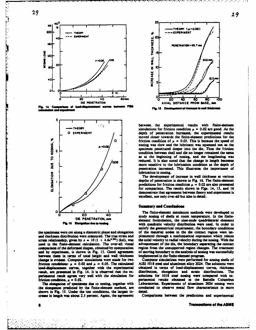
NO 25
a -TREOV (I60.02)"HOR ---- XIIIPII[NT
U)
ZI
A .048 002 413450.
so D ,
W
En 1 I I .. . .
0 2O 40 Gomm 0 20 40 so a0 100Oil[ PENETRqATION AXIAL DISTANCE FRlOM BASE. HllI
14 C wmp~ *I Wa pe s m wM M bew oem = s 0 o p o hm ewe l t N~ maknmlon and exokoo
3 10I I I IlL
between, the experimental results with finite-eement-THEOY simulations for friction condition p - 0.02 are good. As the0 EXPERIMiENT depth of penetration increased, the experimental results
moved closer towards the finite-element predictions for the0 friction condition of p - 0.05. This is because the speed of
,- nosing was slow and the lubricant was squeezed out as theas specimen penetrated deeper into the die. Then the friction
Z condition between shell and die no longer remained the same0as at the beginning of nosing, and the lengthening was
reduced. It is also noted that the change in length becomesWmore sensitive to the lubrication condition as the depth of
penetration increased. This illustrates the importance ofZ lubrication in nosing.
The development of increase in wall thickness at variousdepths of penetration is shown in Fig. 16. The f'inte-dementpredictions for friction condition # - 0.02 are also presentedfor comparison. The results shown in Figs. 14, 1, and 16demonstrate that agreement between theory and experiment isexcellent, not only over-all but also in detail.
Sumary amil Conddins0 The finite-dement simulation methods were developed to
0 20 40 study nosing of shells at room temperature. In the finite-DIE PENETRATION, mm element formulation, the nine-node quadrilateral elements
Pt5.$ U@mtlidt i with quadratic velocity distribution were used. In order tosatisfy the geometrical requirement, the boundary conditions
the specimen were cut along a diametric plane and elongation of the material nodes in the die contact region were im-and thickness distribution were measured. The true stress and plemented through a mathematical expression which relatesstrain relationship, given by a - 10 (1 + 4 .60-2m) (ksi), was the axial velocity to radial velocity during the nosing. With theused in the finite-dement calculation. The over-all visual advancement of the die, the boundary separating the contactcomparison of the deformed shapes, obtained by computation region from the unsupported region changes. The treatmentand by experiment, is shown in Fig. 13. Good agreement of moving boundary in the analysis of nosing was successfullybetween them in term of total height and wall thickness impkmented in the finite-element program.dmn is evident. Computer simuiations were made for two Computer simulations were performed for nosing shells offriction conditions: p - 0.02 and p - 0.05. The calculated AISI 1018 steel and aluminum alloy 2024. The solutions wereladdplacemnt curves, together with the experimental obtained in terms of lood-displacement curves, thicknessresult, are pres ted in Fig. 14. It is observed that the ex- distribution, dongation and strain distributions. Theperimetl result agrees very well with the simulation for solutions for 1018 steel nosing were compared with ex-friction condition, p- 0.02. perimental results obtained at the Battele Columbus
The dongation of specimens due to nosing, together with Laboratories. Experiments of aluminum 2024 nosing werethe elongation predicted by the finite-demnt method, are conducted to observe metal flow characteristics in moreshown in Fig. IS. Under the test conditions, the largest in- detail.crese in tngh was about 2.5 percent. Again, the agreement Comparisons between the predictions and experimental
l n~Traetloma of the ASME

*results were satisfactory, not only over-all but also in detail 4 Cheat. C. C.. and Kobayashi. S.. "Rigid-Plastic. Fisnne-Element Analysis*for both materials, of Ring Cotiipresuion." AAphcation; of Numericsil Met hods to For-mai
Proeses ASME. AMD. Vol. 28.1978. p. 163.Acknowledguawts 5 Nadui. A.. "Planki State of Stress in Curved Shellk: The Forme Required
for Forging of the Nose of Hili-Explosive Shells.,- Forging of Stemi Shells,The authors wish to thank the Army Research Office, presented at the aniual meeting of the ASME. New York. No%. 23-Dec. 1.
Research Triangle Park, North Carolina, for Contract DAAG 1'3.29-79-C-0217 under which the present investigation was 6 Goes, E. T .. ansd Prager, W.. "Nosing of Shells," Technical Report
DA796/15, Brown University. Providenc. 1.1.. 1954. pp. 1-8.- possile. 7 Cruden. A. K., and Thompson. J. F., "The End Closer of Backward
They also wish to thank Dr. G. D. Lahoti, Battelle Extruded Can." NEL Repot No. 311, National Engineering Laboratories.Columbus Laboratories, for providing the detail information Glasgow. 1972.
* on the excperiment using AISI 1018 steel nosing. Thbey further 8 Lahots. G. D., and Altan, T.. "Analysis of Metal Flow in Nosing ofTubular Products." A'oc. &th NAMRC. Manufacturing Engoineering Trans-wish to thank Ikuko Workman for typing the manuscript. action. 1978. p. IS 1.
Rerfsc 9 Labots, G. D.. Subramanian. T. L.. and Altan, T.. "Development of aComputerimed Mathematical Model for the Hot/Cold Nosing of Shells."
* I Shalh. S. N., Les, C. HI.. and Kobayashi. S., "Compression of Tall, Contract Report ARSCD6CR-78019. Battelle Columbus Laboratories. Sept.Circular. Solid Cylinr Between Parallel Flat Dies," Proc. Int. Cott Prod. 1978.ENFs., Tokyo. 1974, p. 295. 10 Tang. M.- C., "An Investigation of the Shell Noting Process by the Finite-
2 Shah. S. N.. and Kobayashi. S.. "Rigid-Plastic Analysis of Cold Element Method,." Ph.D. dissertation. Department of Mechanical Enieering.Heading." A'... 15th Int. Mach. Toot Design & Res. Con!.. 1975. p. W03. University of California, Berkteley, September 198 1.
3 Chen, C. C.. Oh. S. L. and Kobayshi. S.. "Ductile Fracture in I I Oh. S. L.. Rebelo. N.. and Kobayshi. S.. "Finite-Element Formulation* Axisymetric Extrusion and Drawing. Pan 1: Deformation Mechanics of for the Analysis of Planki Deformation of Rate-Sensitive Materials in Metal
Extrusion and Drawing." ASME ioVustAz or EisasNUtanno mit lIN~usrit. Vol. Forming." Metal Forming Plasticity. IUTAM Symposium. Tutzing. Germany,101, No. 1, 1979, pp. 23-35. Aug.-Sept. 1978, p. 273.
r
Prnoted oft U.S.A
7Journal of Engmnering for Industry 7

TH- ANE AN aociv o iMuCHAugR., m 1mimS 82-Prod-15" M36i 7 L . . MW Youk N.Y. S01
E-S The Seeey oim not be eepeIII for ofemeee N onne a.0 nInd p" r in hdiscussi e on 0 f h a of of ftw OVSI of I~m V Gr "VAN to f%.Jdi-bJ publsuisna. Oteusn"s Is I sft ud th e pWis publseld 1 In an Jeusimi.. guimmd far auged pufa~ess epn meusbei. Pul ui ehauld be 0w fo M ME
WaTaeoleW OWiea, w4 she O Po o m v amle ram A&M lt Mus maese
PdsmmdintJA.
3'
44.
An Investigation of the ShellNosing Process by the Finite-
ing-Ching Tang Element Method. Part 2: NosingShir at Elevated Temperatures (HotSan Jose. Cal"f.
ShirKobayashi Nosing)professor. The metal-forming processes of shell nosing at elevated temperatures were analyzed
Depaflmenmt of Mechanical Engineecing,Unives of Califonia. by the finite-element method. The strain-rate effects on materials properties and the
Berkeley, Calif. flow stress dependence on temperatures were included in the finite-element analysis.Fellow ASME A thermodynamic theory of uisco-plasticity based on rational mechanics was
adapted to a rigid-plastic material idealization. An implicit scheme is used for thetime integration of heat transfer. equations, which is coupled to the plasticityequations. The nine-node quadrilateral elements with quadratic velocitydistribution were used for the workpiece, and four-node quadrilateral elementswere used for the die in the heat transfer analysis and temperature calculations. Thecoupled analysis of heat transfer and deformation was applied to the forming ofAISI 1045 steel shells. Correlation between simulation and experimental results aregood.
Introduction
Nosing of large shells (155 mm and above) is done at hot uncouples the problem of heat transfer from the metalworking temperatures. Prior to nosing, the end portion of the deformation problem. The approach was to determine thetube to be formed is heated to temperatures of between 1500 flow characteristics of the problem either experimentally or byto 1900F by tubular wound induction coils. Then the shell is calculations, then use these calculations for the computationnosed by forcing it into a suitably shaped die. When defor- of heat generation and temperature distribution.mation takes place at high temperature, the flow stress of the A paper by Oden, Bhandary, Yapwa, and Chung [11material is a function of temperature and strain rate. The presents the first coupled analysis of deformation and heattemperatures in the shell wall are influenced by (1) preheating transfer for elasto-viscoplastic materials in a three-conditions, (2) heat generation due to deformation and dimensional rectangular bar. Rebelo and Kobayashi (2) havefriction, and (3) heat transfer to the nosing die. Determination made a coupled thermo-viscoplastic analysis in solid cylinderof these temperature distributions along the length of the shell and ring compression. In a previous work by Lahoti,wall is important and necessary in order to predict accurately Subramanian, and Altan [31, the heat-transfer problemthe flow of metal and the nosin& load in the hot nosing, during and after induction heating was analyzed by the finite-
In fact, the temperature distribution is rather critical and difference method. We present here the finite-elementmuch effort has been concentrated on the preheating con-ditions. If the heating is gradual and slow, the unheatedportion of the tube gains heat by conduction. Consequently,the tube tends to buckle under axial load during nosing. "Therefore, preheating is done at a rapid rate so that the high .5 - . 35...-.,-
temperature does not travel back to that part of the shell | /which should remain relatively cold. . . .. ..-------- -. . I
Until recently, most of the temperature calculations duringa metal-forming process have been based on a procedure that .
__________ 2 55-Contributed by the Production Engineering Division for Presentation at the
Design and Production Engineering Technical Conference, Washington. D.C.. S ZS
September 12-I, 1982, of Tun AanA, Socts'y oF MlcU Kuc.LEmomeas. Manuscript received by the Production Engineering Division , a
February 8, 1962. Paper No. 52.Prod. IS.Copies will be available until June 1983. Mg. I1 Wt -pS0
Discussion on this paper will be accepted at ASME Headquarters until November 22, 1982

1 32
MITI
1200-
loop
900I DIE
0 10 20 30 -DISTANCE FROM NOSE TIP
PIg 2 Tmpoa l dbm a 109u10 by h heduo t h fe OaSmNl 0mde1 1 1601m ll 1 40-
simulation for the coupled analysis of metal deformation and'" heat transfer during hot nosing. The results are compared*i with the experimental work by Carlson [41, and with the I WORKPIECE
confirmation testing of hot nosing process conducted by 20Battelle Columbus Laboratories [5]. The effects of tem-perature distribution on nosing are shown and discussed.
Coupled Tbenmo-Viscoplastic Analysis 0 . .
The finite-element equations resulting from discretizingweak forms ofthe equilibrium equations and heat balance 20 40 mmequations were given by Rebelo and Ko ayashi [2]. The finite- Fig. 3 W umfhr ge nolh a mlnmode of S0mMM*Aelement method for the deformation analysis is described inthe accompanying paper [6]. M ,ta
For heat-transfer analysis, heat balance equations upon so TIP TIEMP. • I ' Kfinite-element discretization are reduced to the form ,,oMs s P.o .41 O/.ec
CI+KT-Q, (1) A XPIAIMNTA
where C4 /tO,C - heat capacity matrix - T_.OK - heat conduction matrix 0
Q = heat flux vectorT ,, vector of nodal point temperaturesT - vector of nodal point temperature rates
The heat flux vector Q in equation (I) has several con- O aponents, and is expressed with interpolation function N by o 0._ 1.0 L5 in.
r 0 3 40 m
Q V v(DNdV+ I e(T -TI)NdS, DIE PENETRATIONFig. 4 'u . mat vwrloMoheomotI, es for hot
I of a emoil meda of 106-mm ohel
-. , h(T,-Ts)NdS. term represents the contribution of the heat transferred* Sc s between workpiece and die through their interface. Td and T.
are die temperature and workpiece temperature, respectively.qN r 2 and hLub is the heat transfer coefficient from the lubricant.
The last term is the contribution of the heat generated byfriction along the die-workpiece interface, qf being the
The first component is the contribution of the net heat surface heat generation rate due to friction.generated inside the deforming body, and the fraction v of the Coupling of deformation analysis and temperature
* plastic work rate is assumed to be 0.9. The second component calculation is seen in the scheme of time integration ofis the contribution of the heat radiation from the en- equation (i).vironment, where a is the Boltzman constant, e is the The scheme requires consistency and stability. The firstradiation coefficient, and 7, and 7, are environment tem- requirement is satisfied by an approximation
* perature and surface temperature, respectively. The thirdterm describes the heat convection between body surface and T,+ .T, +A[(I - )1, + t,+j (3)environment with heat convection coefficient h. The fourth where t and At are time and its increment, respectively, and i
2 Tranlactlons of the ASME

P..
Table 1 Sb$ustra, asltlral , m190penore rehido ehips of AISi 14 sled
S.+ ( (unit Ku)
Y - -7.2588xtO-IT + 4.4912x 10 4T - 0.93gT+ -64.6
n - - 0.1743x10-T 3 + 0.1026xi0-T - 0.1917xl0- 2 T+ 1.3
y - -0.1682x 10-To + 0.5285 x 10⁻⁴T - 0.107 + 72.28
Ate - 0.2
Y = -4.9439X 10⁻⁷ "4 + 3.1695x10⁻⁴T1 - 0.69T+ 513.56
n - 0.789x10-97" - 0.4496xl0-57T + 0.8633x10- 2 T- 5.33
-' - -0.501 x 10 -'7T + 0.3057x 10⁻⁴ 7 - 0.062T + 42.06
Ate = 0.3
Y -6.3728x 10-'T + 4.092x 10-472 - 0.8831T + 648.61
n - - 0.588 x 10-974 + 0.3396x 10- 7'4 - 0.6397x 10⁻²T + 4.09
-y -0.85 3x 10 -74 + 0.51910-4' - 0.1053T+ 71.05
Ate = 0.4- -0.8535xl10" 5 T3 + 0.31I9x I0-T 2 - 0.1053T + 71.05
n - -0.2457x 10- 9 T3 + 0.1278x 10-I7T - 0.2046x 10-'T + 1.15
- -0.6617x 10⁻⁹T' + 0.40x 10-T 1 - 0.8441 x i0-T + 5.79
where Tis temperature in *F. Use interpolation to get flow stress for any i < 0.4
KM 'I a radius of curvature of 11.85 in. for an ogive profile. Tol ~ simulate the amount of nosing done on the 105-m shell. 1.45
0wit in. of dhe specimen was made to enter the die, giving a
15 1 /11 maximum reduction in the mean diameter of about 33 per-ssPemueom cent.
/00*11 In preparation for the test, the die was heated for about I hr0 13 .N to bring it to a temperature of 1000F. The testing tem-
i" iperature of the shell was from 1600F to 1900F at the tip. Tor measure the temperature distribution, six chromel-alumel*thermocouples were placed along the shell model. The
measured temperature distributions are shown in Fig. 2.The heating of the shell was done in about I min by an
0 0 induction coil. The ume of nosing was of the order of I s.0 0.9 1.0 ,.3 i, The finite-element simulations were carried out, using the0 2o 40 mesh system and dimensions shown in Fig. 3. A total of 39
il PgNTRATION nodes and 6 nine-node dements were used for the workpiece.pI a ewm O Iw ~, p Nava The die mesh has 13 four-node quadrilateral elements and ast pueta 4. be ti mb, a m.. me di.. l. s total of 52 nodes.
The material properties of the specimen used in the ex-is a parameter varying between 0 and 1. For unconditional periments were very close to that of AISI 1045 steel. Flowstability $ should be greater than 0.5, and a value of 0.75 was stress expressions of 1045 steel were found from experimenadchosen. A detail on an implementation of the algorithm to data of Altan and Boulger [7]. We rgderive the expressionsinclude the coupling of the solution of stress equilibrium and reduce them to fit the relationship, as shown in Table i.equations with het balance in the finite-element program is The heat transfer characteristics were taken from standardgiven elsewhere (61. handbooks:
Hot Nod"g of s Sal Model of 10W-n Shell K. - 30.28 N/s K (workpiece heat conductivity)(pC),. - 3.69 N/mml K (p, density; C,, workpiece heat
To study the nature of the nosing process in the forging of capacity)shells, Carlson [4] conducted hot nosing on a small model of a K, - 19 N/s K (die heat conductivity)105-mm shell. Commercial open-hearth, cold-rolled steel was (pC)d - 3.69 N/mm1 K (p, density; Cd. die heat capacity)used in making the specimens. Geometric details of the h - 0.0692 N/s mm K (heat convection coefficient)specimn are given in Fig. 1. hLOb - 32.88 N/s mm K (heat transfer coefficient from
The die that was employed throughout the experiments has lubricant)
Journal of EnIb neetng for Industry S
K . . " . .a

39.mom"
1227EN? 117
5 __a PONCTIONS I wmcasuT j 0.1
0 L- 00 0.5 1.0 1.5 2.0.. 0 20 3 0 5
I a DISTANCE FROM NOSE TIP. m0 20 40 me ~ Fig. 9 Caumprilson of fial Ilipaatur dlatildbudsaa far dilaunt
Fig. 41 ---- DIE PENETRATION .0 " eP~g 6 -~ igs-, amsfour dHIsta Uilllp tamaalrs
at apsaedeal mlarbm~alugaal maid f MO1064moshl
__ __ __ __ __ __ __ __ __ _KN lbSPE4 1 I/wvsc EXPERIMENT PEN
NOsMn SPE 841 1111AI/ss 1I4"K ?0 - 1 a A1270 '01I- 0 0 U
- I0 0.5 i. lbi
0 20 40im10 10 00*DIE PEI ATO
ll 2 7A Efeto * n lnsi u t iA30
-J%# 0NA 401 -- I
I INTA4I IN tol0 OO$ CL o 41 samos
0 0 20 :0 160 0 200 Fi.1 Flmdsg f1111an"DINERMNOTIP, mm
*~~~nta tip. temperaturestmu..a~~daw~sj at00 127(1 150 (12 *K,
The ~ ~ ~ ~ ~ ~ ~ ~ ~ ~ ~ ~~~ i otrbudreoftedeaesfiinlfafrmte ad 125 (1269 K), rspctively mamt~ nosing nedong
inefcadacntn eprtr sipsdo ie INAL Tnd ?I 0.1.Figr sapo iia to.0 Fig 5, wt
The .O noigsedf_7___18 __.s n 1mms hge oin pe f4 m/.Alo heFMsmlto
(16 in/s wrsiuaebytefnt-emncacltos reutshwdgoagemnwihhexpie nta dtafoTh unfr4eoiyfedeuvlett-h oigsedws % - .I-sosre httensn odicesda h
usda h inta Sus..*Step -t siews25m . oki eprauedcesdIn deomto acltosInaeaeo in trtos Teefc ftmeaueon seleogtonilutae
wa neTeded f IP con ergece plu upm totnmr ostte i i.7 ti oie hta h altmeaueinceaed
wer. nede forS.IM tepeatlurle cantergnce. WFigutarlp W totoe ofsow the mtsafor dit roficiont beor a.1nThaeab -E loadig-, heloddisplacement curves frhtnsn at atroigorntalipem rare obtained by Fnd forin
various friction conditions. withinitial tip temperature a pe f4 m s at 16SF (.15 8j K) 0. 0 (122 K),eno
The5 nosinKg a speed f 6 47m /s (1 i /s) ad 41ve mmsi ig nosing s F peed 47 m/s. ur Allo he FEMsiution0
used 4.Ias th e intalgess te simuae o w ulsase 2.5y mm.s orphecoe tip oeea h oebn emperature deceaed
In deomtoTacltosrnavrg fnn trtos h feto eprtr nseoactions ilUstrate

,too ]0-I *,OO
'Wa 005,
-J /0/
O 2 .tXPgRiMeNT
L_ I 0 I III tII I 0 "I I I I I
0 o i&I o 0 I 00 IS0 =ZDISTANCE FROM NOSE TIP DIE PENETRAT
Mig.12 Twvpeati dilaibutloo of IU.4m1m plion pdrto tinal Ig. 14 Cowmelsm of oamkplauemen cuing from FM@Waleion oud ezpoemti fo I r hot o. off1mm e
600 00
500- 0DI00 00
,00 2 00LO 3
400 0 2 4 6 a to 12 0
DISTANCE FROM NOSE TIP
Pig Is Oute maim tempesium dilbulh at dfllomw de
mm cuffed, the final tempratures r predicted to be higher with
300 greater nosing speed. In the region near the nose base, thetemperatures are the same. More heat is generated whennosing speed increases.
Figure 10 shows maximum force curves during nosing andat initial tip temperature. The considerable scattering of theexperimental results is due to the limitation of the indicator
200 diagram in depicting maximum force. However, a consistenttrend was observed when comparisons were made between
WORK PIECE FEM simulation and experimental results. Deviations betweencomputer and experimental values were about IS percent. Theeffect of nosing speed on maximum force was less obviousfrom FEM simulation than from experiments. This may be
1O due to the fact that the rate-sensitivity constant used in thesimulation is different from that of the material used in ex-~periments.
Hot Nosing of 155-mm Shell
0 Confirmation testing of the hot nosing process was con-0 t O ducted by Battelle Laboratories at Chamberlain Manufac-
mm turing Corp. in order to study the material flow of a selectedFIg.13 Mems, amforPMelilafmollu.mmmileneing preform at hot nosing temperatures. The projectile was that
of a *5-mm shell, and the material was modified AISI 1045.of about 50 K was expected due to conduction heat from the Prutorm dimensions were measured and recorded. Pre-upper portion of the shell to the lower portion. Friction form temperatures were measured, using imbedded ther-condition has very little effect on the temperature mocouples at six places in the region near the nose tip. Detailsdistribution. This means that the heat generated due to of the preform design are given in Fig. I1. The preform wasfriction is small compared to the amount generated by heated to 1400"F at the tip, using the induction coil. Theconvection or conduction. With lower initial temperatures on temperature distribution prior to nosing is shown in Fig. 12.the workpiece, the results in temperature distribution after The nose die has 10.3-in OD and is enclosed by a water-jacket;nosing are similar. A comparison of final temperature typically, the water in the jacket is nearly boiling. The diedistributions for different nosing speeds is shown in Fig. 9. In temperature is estimated at about 400"F.the region near the nose tip where large deformation oc- Water-based graphite was used as the lubricant in the test.
Journal of Engineedrng for Industry 5

360PENETRATO. Z2I'
40'Em
EKPER-ME-I ..O02
40o-223,.
" -I P , /
- 2..,
/ / 0
a 0
125- -20-
-40-
DISTA CE FROM SHEL. BASE PEKTRATIO14 20
fg 16 Comparison of thiknees dictt between PEN WdIotin -Go
ondemporkment
0 EXPERIMEN00T'0
0I flI FIg. 16 Straon distributions at pmnetrpon 1of220 m
EXPERIMENT
2
0 2 4 a l 1onI .. I_____________________O 00 200..m
IE PINETRAI ON
Fig. 17 Elongation dAng hot nosing
The ram speed of the 0O-t mechanical press was 2.5 in. (63.5mm) per second in carrying out the nosing process.
The mesh system for the finite-element simulation was builtwith 39 nodes and 6 nine-node elements in the workpiece, and56 nodes and 39 four-node elements in the die. The initial gridis shown in Fig. 13. Total penetration of the shell into thenosing die was about 225 mm, obtained in 14-mm steps. Aconstant temperature was imposed on the outer boundaries ofthe die.;'t Flow stress expressions for AISI 1045 and the heat transfer
characteristics were the same as described in the previoussection. Fig. 19 Comparison o deformed sh between FEM end ex.
The load-displacement curves that were obtained from P"iWntfinite-element simulations for various friction coefficients arecompared with experiments in Fig. 14. The ring-compression Temperature rises as expected around the contact areas intest gave a value ofps N 0.09, and from FEM results this value the die, and the differences between workpiece and die
" was considered to be too high. A value of p IN 0.02 or smaller temperatures decrease substantially during the course ofgives simulation results closer to that in the experiments. Near deformation.the end of nosing, the experiments showed a steeper increase A comparison of thickness distribution along the shell isin the load than did the FEM, possibly because the lubricant given in Fig. 16. Thickness distributions at several penetrationwas squeezed out, thereby increasing friction. depths are predicted by the FEM model. An increase of
The temperature distributions of the shell outer surface at penetration depth increases the thickness for a given point.. different penetration depths are presented in Fig. 15. As the Also, the region of wall thickening extended towards the nose
contact between die and workpiece increases, the temperature base. A consistent trend was observed when comparisons wereof the workpiece in the contact region gradually decreases due made between computer-calculated wall thickness and ex-to heat flow from the workpiece to the colder die. The test perimental results.results showed product temperatures of between 900 and 1000 The 155-mm shell length increases after hot nosing underK, which agree with the average temperature distribution good lubrication, as shown both by experiments and by FEMfrom the FEM. simulation. Figure 17 gives shell elongation versus die
6Transactions of the ASME

penetration during hot nosing. An increase in length of 8 mination of deformation characteristics, in particular thepercent is expected after penetration of 220 mm. Recall that thickness changes, as functions of process variables isonly 4 percent elongation was expected at the end of nosing essential. Some factors which influence deformationfor a 105-mm shell. This indicates more elongation for larger characteristics significantly are the temperature distributionreduction in mean diameter in shell nosing. along the cylinder, friction along the die, and pressing speeds.
In Fig. 18 we plotted the distributions for axial strain e , The coupled analysis of heat transfer and deformation wasradial strain e,, and circumferential strain e &t die performed by simulating nosing of a 155-mm shell of AISIpenetration of 220 mm, The compatibility is satisfied as the 1045 steel. Experimental results were available from Battellesum of f,, ez, eo remains zero. The axial strain e, does not Laboratories, and correlation was good.show negative value near the nose base as it did in the cold By using the finite-element programs developed in thisnosing simulation. This suggests that lengthening takes place research, we are able to obtain such detailed deformationin the entire nosed portion of the shell. characteristics as: load-displacement curves, thickness
The deformed shape of the nose from FEM simulation is distribution, elongation, strain and strain-rate distributions,compared to that of the experiment in Fig. 19. Since the and temperature distributions. They are valuable for thepreforms are not exactly the same in the region near the nose control of the nosing process, design of equipment, andtip, the FEM predictions did not match the experiments, preparation of workpieces.Additionally, the FEM model showed a nosing limit beyondwhich material can no longer support the nosing load, and a Acknowledgmentschange of deformation mode (e.g., buckling) may occur.Therefore, the maximum depth of penetration was also The authors wish to thank the Army Research Office,different for the FEM model. The discrepancy may arise from Research Triangle Park, North Carolina, for Contract DAAG
the fact that the flow stress expressions implemented in FEM 29-79-C-0217 under which the present investigation was
calculations could be different from those of the materials possible.
used in experiments. They also wish to thank Dr. G. D. Lahoti, BattelleColumbus Laboratories, for providing the detail informatonon the experiment using AISI 1018 steel nosing. They further
Summary and Conclusions wish to thank Ikuko Workman for typing the manuscript.
In this investigation the finite-element simulation methods Referenceswere developed to study nosing of shells at elevated tem-peratures. The deformation analysis and heat transfer I Oden, J. T.. Bhandari. D. R.. Yagawa. G., and Chung. T. J., "A New
analysis, including dies, were coupled together for an iterative Approach to the Finite-Element Formulation and Solution of a Class of
simultaneous solution. The nine-node quadrilateral elements Problems in Coupled Thermoelastoviscoplasticity of Crystalline Solids."Nuclear Eng. Design. Vol. 24.1973. p. 420.
with quadratic velocity distribution were, used for the ' 2 Rehelo. N., and Kobayashi. S.. "'A Coupled Analysis of Viscoplasticworkpiece, and four-node quadrilateral elements were used in Deformation and Heat Transfer-I and I1," Int. J. ech. Sc,.. Vol. 22, 1960,the die for the heat transfer analysis and temperature pp. 699-718.
calculations. 3 Lahoti. G. D.. Subramanian. T. L.. and Altan. T.. "Development of aComputeriz.d Mathematical Model for the Hot/Cold Nosing of Shells."The equations that describe the deformation mechanics are Contract Report ARSCD-CR-78019. Battelle Columbus Laboratories. Sept.
nonlinear and were solved by Newton-Raphson's iterative 197s.technique. An implicit scheme was used in the time in- 4 Carlson, R. K., "An Experimental Investigation of the Nosing oftegration of heat transfer equations which provides good Shells," Forging of Steel Shells, presented at the Winter Annual Meeting of theaccuracy for a reasonably large range of time steps. The die ASME. New York. Nov. 29-Dec. 3, 1943.
5 ahoti, G. D.. "Confirmation Testing of Hot Nosing of MI07 155-mmpart was remeshed after each deformation step. Shell." unpublished data, Battelle Columbus Laboratories, Sept. 1980.
Finite-element programs were written in FORTRAN IV for 6 Tang. M. C.. and Kobayashi, Shiro. "An Investigation of the Shella CDC 7600 computer. Listing of these programs, including Nosing Process by the Finite-Element Method. Part 1: Nosing at Room
Temperature (Cold Nosing)," submitted for publication in ASME JOURNAL OFinstructions for input data preparation, are given in reference ENour'EaIoNG FOR INDUSTRY, 1982.[81. 7 Altan, T., and Boulger. F W.. "'Flow Stress of Metals and its Ap-
It is important to determine the precise shapes of the plication in Metal Forming Analysis," ASME JOURNAL or ENGINaEEINO FeOprofiles of shells (thickness distribution) in the original INDUSTRY, Vol. 95. No. 4, Nov. 1973, pp. 1009-1019.
8 Tang. M. C.. "An Investigation of the Shell Nosing Process by the Finite-cylindrical forgings to produce the prescribed shapes of shells Element Method," Ph.D. dissertation. Department of Mechanical Engineering,in their finished ct" dition. For this requirement, the deter- University of California, Berkeley. Sept. 1981.
Primed in U.S.A.
Journal of Engineering for Industry 7

ANALYSIS OF SHELL NOSING --
PROCESS MECHANICS AND PREFORM DESIGN+
Ming-Ching Tang*
May Hsu**
Shiro Kobayashi***
ABSTRACT
The finite-element method for rigid-plastic materials is used for theanalysis of nosing of aluminum alloy 2024 tubular preforms with uniforin wallthickness at room temperature. The detailed mechanics were obtained bycomputer simulation and some of the results, such as load displacementcurves, elongation and thickness distributions, were compared with experi-mental results. Then, assuming that the strain distributions computed bythe finite-element method are valid for preforms having nonuniform thick-nesses initially, two types of preform shapes were desiqned to obtain uniformwall thickness after nosing. Experimental results of nosing these preformsshowed that the approach to the problem is satisfactory.
February, 1982
4
* IBM, San Jose, California
** KLA Instruments, Santa Clara, California
* Department of Mechanical Engineering,University of California, Berkeley
q+ The paper is in press and no clean copy is available at the present time.
7

ANEW APPROACH TO PREFORM DESIGN INSb. METAL FORMING WITH THE FINITE ELEMENT METHODt
by
J. J. Park*, Nuno Rebelo** and Shiro Kobayashi*
ABSTRACT
A new approach to preform design is i-ntroduced, as a unique application
of the finite element method to the problems in metal forming. The concept
involved in the approach is to trace backward the loading path in the actual
forming process from a given final configuration using the finite element
method. The concept was tested with the problem of simple compression of a
cylinder and the method was applied to preform design in shell nosing.
t Part 1 of "Preform Design in Metal Forming"
* Department of Mechanical Engineering, University of California,
Berkeley, California
** Brown Boveri Research Center, Switzerland

1. INTRODUCTION
One of the most important aspects of the closed die forging process is
the design of preforms. An example of preform design for steel finish forg-
ings of various H-shapes is shown in Fig. la. Preform design involves the
determination of number of preforms and design of the shapes and dimensions
of each preform. According to Biswas and Knight [1], the bulk of the work to
determine the preform shapes for complex forging components has been carried
out in Germany and the Soviet Union, as reported by Spies [2]. Chamouard [3]
in France, and Akgerman et al. [4] in the U.S. dealt with some practical pro-
blems of preform design for certain forging cross-sections. The present prac-
tice to this complex problem is to computerize the design calculations required
l for the designer's decisions, based on qualitative guidelines which have been
derived mainly from experience or experimental studies.
Preform design problem is also involved in shell nosing. Shell nosing is
the process of forming an ogive nose at an open end of a tubular part (preform)
by pressing the tube into a contoured die. Wall thickness increases, but the
shell may elongate or shrink in length during nosing. Because shell. specifi-
cations usually require certain wall thickness distributions after nosing, the
problem is to design the preform with which the desired shape after the nosing
operation can be achieved. An example of such a preform is shown in Fig. lb.
* The approach to the preform design in shell nosing has been more quanti-
tative, because the number of variables involved in the determination of pre-
*form shapes in shell nosing is fewer than those for preform shapes in general
*9 forgings. Nadai [5] outlined an approach for designing the preforms for
shells with uniform wall thickness after nosing, based on the strains in the
shell nose. Carlson [6] extended Nadai's approach and suggested the method
*q for determining the original shell profile. Based on Carlson's methqd, Lahoti
et al. [7] developed a computer program for the preform design.
S
2$
In this paper a new approach to preform design is introduced. The concept
involved in the approach is to trace backward the loading path in the actual
forming process from a given final configuration by the finite element method.
The concept was tested with the problem of simple cylinder compression and the
method was applied to preform design in shell nosing. Because the computa-
tional technique uses the finite element method, a brief description of the
finite element method is given, and the new approach to the problem follows.
2. FINITE-ELEMENT METHOD
The concept of the finite-element method is one of discretization. The
finite-element model is constructed in the following manner. A number of
finite points is identified in the domain of the function, and the values of
the function and its derivatives, when appropriate, at these points are speci-
fied. These points are called nodal points. The domain of the function is.
represented approximately by a finite collection of subdomains called finite
elements. The domain then is an assemblage of elements connected together
appropriately on their boundaries. The function is approximated locally with-
in each element by continuous functions which are uniquely described in terms
of the nodal point values associated with the particular element. The path to
the solution of a finite-element problem consists of five specific steps:
(a) the problem, (b) the element, (c) the element equation, (d) the assemblage
of element equations, and (e) the numerical solution of the global equations.
The basis of finite-element metal flow simulation, using the variational
approach is to formulate proper functionals, depending upon specific constitu-
tive relations. The solution of the original boundary value problem is ob-
tained by the solution of the dual variational problem where the first-order
variation of the functional vanishes. Choosing an approximate interpolation
function for the field variable in the elements, the functional is expressed

locally within each element in terms of the nodal point values. The local-
element equations are then assembled into the overall problem. Thus, the
functional is approximated by a function of global nodal point values. The
condition for this functional to be stationary results in the stiffness equa-
tions. For metal-forming problems the stiffness equations are nonlinear and
solved by the Newton-Raphson iterative method.
For rigid-plastic materials, obeying the ises yield criterion and its
associated flow rule, the incompressibility constraint can be removed by intro-
ducing either the Lagrange multiplier or a penalty function into the functional.
If the body contains a rigid region, the stresses in the region cannot be
determined. This difficulty is handled by considering an offset of the effec-
tive strain rate, which is several orders of magnitude smaller than the aver-
age strain rate in the deforming zone. The deviatoric stresses ire assumed to
vary linearly from zero to the flow stress if the effective strain rate is
smaller than this offset value. This stress-strain rate relation in the "nearly
rigid" region modifies the functional accordingly.
For rigid-viscoplastic materials, the constitutive equations derived from
the viscoplastic theory are similar to those of rigid-plastic materials except
that the yield stress is a function of strain and strain-rate. Applications
of these methods to various metal forming problems are given in a review on- the finite element method and metal forming process modeling [8]. Recently,
Oh [9], at the Battelle Columbus Laboratories has accomplished a significant
development of a user-oriented general purpose FEN program, namely a rigid-
viscoplastic FEM Code ALPID. The special features of the program include:
(1) use of higher order elements, (2) general description of die and automaticL
handling of die boundary conditions, and (3) automatic generation of initial
guess for iteration procedure. The program ALPID was used for the computation
throughout the present Investigaton.
U "

14
3. METHOD OF APPROACH
A method of approach is illustrated in Fig. 2. At time t = to, the geo-
metrical configuration x0 of a deforming body is represented by a point Q.
The point Q is arrived at from the point P whose configuration is given as
x01 at t =to 1, through the displacement field uo.1 during a time step At, namely,
x0 = o. + Uo 1. Therefore, the problem is to determine uo-1, based on the
information (x0 ) at point Q. The solution scheme is as follows: taking a
loading solution u (forward) at Q, a first estimate of P can be made accord-(1) = x - u Then, the loading solution Cl)
ing to p -O -o o-1 can be calculated onthe basis of the configuration of p(l) with which the configuration x0 at Q
can be compared with p(l) + u(1 Q(1). If Q and Q(l) are not sufficiently-0-1
close to each other, then p(2) can be estimated by p(2) = x - u(1). The sol-ution for loading at p(2 ) is then u(2) and the second estimate of the con-
-0-1figuration (2) = p (2) + can be made. The iteration is carried out until
(n) = p(n) + u(n) becomes sufficiently close to Q. Displacement solutions
are computed by the finite element method. The sufficient condition for con-
vergence is that the body is plastically deforming at all times, if the bound-
ary condition does not change at P and Q. We call this calculation scheme
"Backward Tracing by FEM." So far, the concept includes only the geometry of
deforming materials, and some questions as to its applicability to real pro-
blems arise immediately. Some of them are: (i) how to include the effect of
material properties, such as work-hardening, strain-rate, and temperature
effects; (ii) how to modify the method when the boundary conditions change;
and (iii) the problem of solution uniqueness.
Although complete and satisfactory answers to these questions await fur-
ther investigations, a test with axisymmetric compression of a cylinder demon-
strates that the concept does work.

5
A circular cylinder of height-to-diameter ratio equal to 1 is compressed
between two parallel platens with friction (friction factor, m = 0.5) to 10
percent reduction in height. The material is assumed to be rigid-perfectly
plastic. In Fig. 3 the workpiece configuration at 10 percent reduction is
shown by dotted lines as the result of rigid-plastic finite-element simula-
tion of loading. Now, the backward tracing scheme was applied to the known
configuration at 10 percent reduction in height. After the 10 percent axial
displacement was traced backward, the result indeed gave the circular cylinder
as the preform.
For both forward loading and backward tracing, a step size of 1% reduc-
tion in heightwas used. Because of the use of Newton-Raphson method in the
finite-element program, iteration is involved in obtaining a loading solution
(forward iteration), and another iteration is necessary in the backward trac-
ing scheme (backward iteration). Numbers of iterations for each step of de-
formation were 6 - 7 and about 3 for forward and backward procedures respec-
tively. Closeness of the two configurations Q(n) and Q was measured by x0 -0
and the limit was set as 0.005 (mm), where xn represents the coordinates of
(n)the configuration of Q
It should be noted that the process reversal (reverse loading) by revers-
ing the direction (sign) of the boundary conditions does not trace the loading
4 path backward, because the process reversal is a different boundary value pro-
blem from that of loading. Figure 3 shows that clearly the shape that is
obtained by reverse loading did not result in the original circular cylinder.
4. APPLICATION TO SHELL NOSING
Preform design in forging is complex and generally involves many problems
in applying the new approach. Less complex is the preform design in shell
nosing, because the number of parameters in defining preform shapes is fewer.
U

• •
6
In shell nosing, two simple preform configurations can be realized for a uni-
form wall thickness after nosing. The wall thickness distributions required
in the preform can be accommodated by varying either the inner or the outer
diameters of the preform. It is not difficult to see that different preform
configurations can be arrived at by imposing different sequences of boundary
conditions (such as where and when the nodal point in contact with the die
should be freed from the die) during the backward process. This aspect of the
problem is first investigated for non-workhardening materials. Then, using
work-hardening materials, the procedure to include the effect of work-hardening
is introduced in the new approach.
Rigid-perfectly plastic materials:
With reference to Fig. 4, specifications of the final nosed shell con-
figuration are given by (unit; mm)
Lf = 48.84 ro = 21.526 bf . 14.47
(L0 = 47.26) r i = 14.648 hf = 6.88 (uniform)
R = 259 (ao = 237, bo = 18.75)
Coefficient of friction at the die-workpiece interface is assumed to be u = 0.05.
For the finite element calculation, 40 four node elements and 63 nodal points
are used. The criterion for controlling the boundary condition during the
backward tracing depends on the preform shape under consideration.
For the preform shape with constant outer diamter (Type-0 preform),
rno = ro for all n, where ro 0is the radius of a nodal point located along the
outer surface of the shell. The boundary condition for this type of preform
is controlled in such a way that nodes which are in contact with the die
(rn < ro ) are freed from the die when the condition that rn = ro is reached
during the backward tracing.
For the preform shape with constant inner diameter (Type-I prefQrm),

7the criterion for changing the boundary condition is that as soon as r? =r
for the nodes rp < ri, the boundary condition of the corresponding outside
node is changed from that of die-contact to the force free condition, where
rp is the radius of a nodal point along the inner surface of the shell.
The above criteria, however, result in some errors because the deforma-
tion of the shell is not confined within the die, but extends beyond the die-
entrance. In order to reduce the error, the criteria for change of the
boundary condition are modified as
r = ro - A for Type-0 preform
r= r i - Ai for Type-I preform
The amount a in the modified criteria can be estimated, for example, from the
loading simulation of nosing with a preform of uniform wall thickness.
Using the modified criteria for controlling the boundary condition, the
computation of backward tracing was carried out taking 2 mm penetration (in
loading) as one step (total 22 steps to complete the calculation). Solution
convergence needed about 6 - 7 iterations and for completing one step backward
tracing 1 - 2 iterations for the case where boundary condition does not change,
2 - 3 iterations are required for the case where change in the boundary condi-
tion occurs. Convergence for backward tracing was determined by closeness of
the solution within the limit of 0.005 (m). The two types of preforms
determined by the method are compared with the final nose configuration in
0 IFig. 5. In Fig. 5, the lengths 0 and E0, for Type-0 and Type-I preforms,
respectively, indicate the portion of the preform which becomes the nosed
shell length Lf after nosing. Because the shell elongates during nosing, the
preforms are shorter than the nosed shell. It can also be observed that the
Type-0 preform is slightly shorter than the Type-I preform. This is~because
the amount of deformation involved in nosing is more for Type-0 than for

8 17
Type-I, and the total elongation is larger for the Type-O preform. The thick-
ness distributions in the two preforms are compared in Fig. 6. The distribu-
tions are almost the same for both preforms, except that the thicknesses in
Type-O are slightly smaller. This is reasonable based on the amount of
deformation involved, and from the condition of volume constancy.
Work-hardening materials:
The following specifications of the nosed shall are used:
material * Al alloy 2024, annealed, with the stress-
strain curve given by
= 68.9 (1.0 + 4.6(Z)0'29 ) Mn/rm2
Die geometry (mm): same (R = 259, ao 237, b° = 18.77)
Shell dimensions (mm): Lf - 36.84, bf a 16.369,
r o = 25.526, ri = 14.648, hf = 6.89
Die-workpiece interface conditions: = 0.
The shell configuration (in terms of total penetration) is different from the
previous non-workhardening case. The reason for the. use of different nosed
shell specifications is that there exists a limit beyond which nosing cannot
be continued and cylindrical part of the shell begins to deform. This limit
depends on the work-hardening characteristics of the material, and the present
specifications are selected within this limit.
In order to include the work-hardening effect in preform design, it is
necessary to know the strain distributions in the nosed shell, in addition to
the geometrical configurations, but the strain distributions in the nosed
shell depend on the preform shapes, and are not known (or cannot be specified).
In Fig. 7 the procedures to take into account the work-hardening effjct in the

49
present approach are illustrated.
Applying the backward tracing scheme for non-work-hardening materials
explained in the previous section, the two types of preforms can be determined.
With these preforms the loading solutions are obtained for a work-hardening
material. The results provide the strain (effective strain) distributions
and the nosed shell configurations. The configurations are very close but not
identical to the specifications. These configurations, mainly, the thickness
distributions, are, then, corrected exactly according to the specifications,
maintaining the same effective strain distributions. With these strain dis-
tributions, the application of the backward tracing scheme results in the
preform shapes for a work-hardening material. At each step, the strain and
corresponding stress are also traced backward following the stress-strain
curve of the material. It should be mentioned that the first computational
procedure in Fig. 7 may be eliminated by using approximate solutions [10] for
preform shapes of non-work-hardening materials.
The number of iterations required was about the same as for non-work-
hardening materials. However, solution convergence is somewhat sensitive to
the size of time step, and a reduction of step size to 1 mm penetration was
necessary. This step size required total 30 steps for completing the computa-
tions.
The effective strain distributions in the nosed shell obtained from load-
ing solutions for both types of preforms are shown in Fig. 8. The strains are
larger for Type-O preform than for Type-I preform. The preforms for the work-
hardening material were determined by applying the backward tracing scheme to
the nosed shell with the strain distributions shown in Fig. 8, and the speci-
fied geometrical dimensions. The effective strains in the preforms were in-
deed negligible (within 0.1% strain), when the backward tracing calcwlation
was completed. The thickness variations in the preform of the work-
6

• JO
hardening material is compared-with that of non-work-hardening materials in
Fig. 9(a) for Type-O preform and in Fig. 9(b) for Type-I preform. Fig. 9
shows that the preform shapes for work-hardening and non-work-hardening mater-
ials are almost identical to each other for both preform types. It may be due
to the fact that the total penetration of the shell into the die is so small
that the work-hardening effect is negligible for this specific case. Never-
theless, it suffices to show the procedure to include the work-hardening
characteristics of the material in the backward tracing technique.
5. CONCLUDING RE14ARKS
A new technique, called backward tracing scheme, was devised for preform
design. This is a unique application of the finite element method to the
problems in metal forming. It was demonstrated that the technique can be
applied to preform design in shell nosing. It was also revealed 'that one of
the critical aspects for further development of the technique concerns with
the treatment of the boundary conditions. The boundary conditions for non-
steady state forming processes change during loaaing, and the way in which
this change occurs depends on the preform shapes. Thus, the criterion for
the selection of desired (or optimum) preform are needed, and then the con-
dition for controlling the boundary conditions, corresponding to a selected
preform must be developed.
A challenge to this new approach for further development, thus, lies in its
application to preform design in forging.
ACKNOWLEDGEMENTS
The authors wish to thank the Army Research Office, for its contract NcO.(od -rho- Na'rov%*.L SC.A"ce Foundts ± A/EA-*ay1284DAAG Z9-79-C-OZ0l7lfnder wichL the present investigat ion was carried out. Tney
;Aalso wish to thank M~rs. Carmen Marshall for typing the manuscript.

REFERENCES
1. S. K. Biswas and W. A. Knight, "Computer-aided design of axisymmetrichot forging dies," Proc. 15th Int. MTDR Conference, 1974, pp. 135-143.
2. K. Von Spies, "Intermediate forms in drop forging and their productionby roll forming," West Deutscher Verlag, Cologne, 1959. (Translated byMinistry of Technology, 1969).
3. A. Chamouard, Estampage et Forge, 1964, Dunod (Paris).
4. N. Akgerman, J. R. Becker, and T. Altan, "Preform design in closed dieforging," Metallurgia and Metal Forming, Vol. 40, 1973, p. 135.
5. A. Nadai, "Plastic state of stress in curved shells: The forces requiredfor forging of the nose of high-explosive shells," Forging of SteelShells, presented at the annual meeting of the ASME, New York, November2-through December 3, 1943.
6. R. K. Carlson, "An experimental investigation of the nosing of shells,"Forging of Steel Shells, presented at the annual meeting of the ASME,New York, November 29 through December 3, 1943.
7. G. D. Lahoti, T. L. Subramanian and T. Altan, "Development of a computer-ized mathematical model for the hot/cold nosing of shells," ReportARSCD-CR-78019 to U.S. Army Research and Development Command, September1978.
8. S. Kobayashi, "A Review on the Finite Element Method and Metal FormingProcess Modeling," J. App. Metalworking, Vol. 2, No. 3, 1982, p. 1.
9. S. I. Oh, "Finite Element Analysis of Metal Forming Processes withArbitrarily Shaped Dies," Int. J. Mech. Sci., Vol. 24, 1482, p. 479.
10. S. Kobayashi, "Approximate Solutions for Preform Design in Shell Nosing,"submitted to Int. J. Mach. Tool Des. Res., 1982.
I
I
I

12
FIGURE TITLES
Figure 1(a) Preforms for finish forgings of various H-shapes.
Figure l(b) Preform for 155 mm shell.
Figure 2 Concept of the backward tracing scheme.
Figure 3 Test of the backward tracing scheme for compression of acircular cylinder.
Figure 4 Die dimensions and nosed shell configuration.
Figure 5 Nosed shell configuration and two types of preform shapesfor non-work-hardening material s.
Figure 6 Thickness distributions in the two preforms (non-work-hardening materials).
Figure 7 Schematic illustration of the procedures to include the
work-hardening effect in preform design.
Figure 8 The effective strain distributions in the nosed shellbased on the two types of preform shapes.
Figure 9 Comparison of the thickness distributions for non-work-hardening and a work-hardening (Al alloy 2024 annealed)materials in (a) the Type-O preform and (b) the Type-Ipreform.
I

~- - ~ - - ~ - Upset stock
None Pre form
___________ trmmed
- 9 Finish
h hb h =2b h=3b
(a) Wb (c
Figure 1(a) Preforms for finish forgings of various H-shapes.
14 9.975 10.0 20(Tol controlled) .-.
T6.16
E0.67 0
Units in inches
Figlbre 1(b) Preform for 155 mim shell.

x~~ I
*d
t 0to-1 Time
Figure 2 Concept of the backward tracing scheme.

!59
z(mm)
Original Configuration100and Backward Tracing Scheme Prediction
-Reverse• -- - - - 0- - Loading
! ii
6 ,.0% HeightI Reduction
50 I
I
I
ii0I1S0 I I ,. , I I I I, I
0 50 00 (mm) R
Figure 3 Test of the backward tracing scheme for compression of acircular cylinder.
I

z
Lf
Fir 4 Entranig
Figure 4 Die dimensions and nosed shell configuration.

Type-O - - -- - - -Type-I
CI Lf I
--- j -
01 Lf
1 1 1 1 I tI I
ig 5Loe hl ofgrto n w ye fpeomsaefo no-okhad n matrils

5-7
.0
01Q Type-I
0
~ -20(C/ro), :2.09
0 1.0 2.0.
C/rw
Figure 6 Thickness distributions in the two preforms (non-work-hardening materials).

a. E
00
.0
h. Q
r~
E EP 4)
. 2 v.4AQ
AL
TEc
TO 0
0 b.
- I. Z
cl 0
V @)

Type-I Type- 0
0.297- 0.3160.218- - 0.2400.162 - 0.1810.118- 0.1320,080- 0.0930.053- -0.0600.030- 0.0350.016- 0.0180.007- -0.0090.003- - 0D030.001- 0.001
Is II
at sIt IsIs II
to I1
It It
5I II
II
Figure 8 The effective strain distributions in the nosed shellbased on the two types of preform shapes.
L . . . .. . . .. . - -

TIf-I
1.,10 .
iD
(a) Type-O0 a0
-ID
11
0T 0 Work hardeningIIx -20 -0 Non work hardening
' (b)Type- I
Fi0 I.O0 /r 2.0
L ,llFigure 9 Comparison of the thickness distributions for non-work-hardening and a work-hardening (Al alloy 2024 annealed)
ii materials in (a) the Type-O preform and jb) the Type-I,- ' preform.

APPROXIMATE SOLUTIONS FOR PREFORM
DESIGN IN SHELL NOSING*
by
Shiro KobayashiDepartment of Mechanical Engineering
University of CaliforniaBerkeley, California
ABSTRACT
Two approximate solutions for preform design in shell nosing are derived.
The degree of approximation was examined by the accurate numerical solution
based on the new approach by the finite element method, for an example of
uniform wall thickness of the nosed shell. It was demonstrated that both
approximate solutions are useful in design, one for its simplicity and the
other for its accuracy. The approximate solutions presented here will also
be helpful for the further development of the new approach to preform design
in shell nosing.
* Part 2 of "Preform Design in Metal Forming."

Nomenclature
r, e, z - radial, circumferential and axial coordinates in the cylin-
drical system
s - coordinate along the die contour
- angular coordinate
- the value of 0 corresponding to the nose tip where the
reaius is equal to b
V s - velocity in the s-direction
a cs , a0 - stress components in the s-direction and the circumferential
direction, respectively
a 0o - flow stress (constant) of the material
s' 8' n - strain-rate components in the s-direction, the circumferen-
tial direction and the thickness direction, respectively
R - radius of the die contour
ao , b0 - r, z - coordinates for the center of radius of the die
contour
Lp - length of the preform
r o , so - r coordinate and corresponding s coordinate at the entrance
of the die
hi , h - tube thicknesses in the preform and in the nosed shell,
respectively
b, B - radius and corresponding s-value at the nose tip of the
shell
bt, B{ - radius and corresponding s-value at the nose tip of the
shell when an element & just begins to deform
q{ - axial coordinate in the preform
t -time
f - subscript referring to the final configuration
4 m umi au - i mm um ~ , ,.. ,.,h . .. ..

'3
1. INTRODUCTION
Shell nosing is the process of forming an ogive nose at an open end of a
tubular part by pressing the tube into a suitably formed die. The internal
cavity of a tubular part (preform) is formed to finished shape through a
series of piercing and drawing operations, and the open end of the preform
is then contoured by a nosing press, as shown in Fig. 1. The metal flow in
nosing is complex. In general, wall thickness increases, but the shell may
elongate or shrink in length after the operation, depending upon friction.
Understanding the deformation mechanics of the process is an essential step
toward the control of metal flow and proper design of the process.
Because shell specifications require certain wall thickness distributions
after nosing, the design of the preform with which the desired shape after the
nosing operation can be achieved is a very important problem. For certain
shells, uniform wall thickness is required, whereas, in other shells, wall
thickness distribution after nosing is defined by two ogive radii.
For shells with uniform wall thickness after nosing, Nadai [l] outlined
an approach for designing the preforms based on the strains in the shell nose.
Using Nadai's approach, Carlson [2] suggested the method for determining the
original shell profile, knowing the final shape. The formulation for the dis-
tribution of thickness in the preform was derived from the geometry of de-
formed configurations and assumed distributions of the strains. Thus, the
final expression for the determination of preform thicknesses requires an
estimate of a quantity, for example, elongation at the tip of the nose.
Lahoti et al. [3] developed the computer program for the preform design pro-
cedure based on Carlson's method. Tang et al. [4], assuming that the strain
distributions that resulted from the finite-element simulation are valid for
preforms having nonuniform wall thickness, designed two types of preform

2
shapes to obtain uniform wall thicknesses after nosing. In this paper two
approximate solutions for designing the preforms are presented. The degree
of approximation of the solution is examined by the accurage numerical solu-
tion based on a new approach by the finite element method [5], for the case of
uniform wall thickness of the nosed shell.
2. PRELIMINARIES
Figure 2 shows the die geometry and the coordinate system. In the cylin-
drical coordinate system (r, z, e) with the origin 0 at the die entrance, the
die contour is expressed as r = R sin¢-a , and z = R cos -b . The coordinate
s measures the distance along the die contour from the origin 0' where r = 0.
With reference to Fig. 2, and using the notation given in the nomenclature,
the basic equations for shell deformation are given by
(i) equilibrium equation
(h + h(- h o (c - e) --o (1)
(ii) yield condition (plane stress)
2 + 2 2 (2)
(iii) flow rule
2 a 23)2 s -ae o - (e +s)
where strain-rates are defined as
a* s avs
= - "cost (Vs < 0) (4)
h
K

3
Since the thickness h in general is a function of coordinate and
time t, the incompressibility condition is written as [6,7]
l Vs Vs1 Dh + cos + -coso = 0
(5)
where D + V cos€weeDt 3t s 3
Note that if h is a function of space variables only, eq. (5)
is reduced to
ddd (h r Vs) 0 (5a)
In Fig. 3 the initial and the two configurations of the shell nose are
shown. Figure 3(b) shows the configuration of shell nose at a time when the
element & just begins to deform, and characterized by the radius of nose tip
denoted by b = b Identifying an element in the initial and the deformed
configurations, the incompressibility equation can be written as
h • r • ds -hi * ro • d& (b, constant) (5b)
and
h.i = r ds (6)h ro d&
When the final configuration is specified, the radius of nose tip b is given
and h is known as a function of r. Thus the problem essentially is to determine
the relationship between the corresponding coordinates in the initial and
final configurations, namely, the relations between & and s (or and r).
3. APPROXIMATE SOLUTION
Procedures:
Taking the magnitude of the velocity Vs at the nose tip as unity, the
nose tip coordinate B (or b) can be used as the time scale (dt • - da =
-db/cos~b). Then, applying the condition that B - s at , 0 and B = Br

4
at , we have
B
f s (Vs) dB (7)
From the definition of the velocity Vs9
IV = (ds) (8)
with the initial condition that s = so at B = B The subscript in eq. (8)
denotes an element E. Thus, the relationship between and s (or and r) can
be obtained by eliminating B from eqs. (7) and (8), when the velocity V S is
known. The determination of the velocity Vs is achieved from
SsVs 20s - ( Vs~T~ -) (9)F 2ac as
resulting from eqs. (3) and (4).
Integration of eq. (9), with approximate stress solutions [8], given byas a0C -kn b , and -C - , results in
a0 b Y0
IVs I (b) 0b (10)r (I))
The derivation of Eq. (10) is given in the Appendix. In order to perform inte-
gration of Vs , involved in Eqs. (7) and (8), further approximation of the velo-
city solution (10) is necessary, and the final solution for pre-form shapes de-
pends on this approximation.
Solution I:
A simple approximation [9] for the velocity Vs is given by
IV I =V (11
The velocity distributions given by eqs. (10) and (11) are compared in Fig. 4.
I
Subsitutng e. (1) ino eq (7

5 67
withr -J:(. F d _ G(r_ G(b~) (12)
oos0 °b, ro 12~wi th
G(x) = dx, V _(x_.oaFrom eq. (8)
dr COS'bIVs1 db coso r
Integrating from r0 to r for r and from b to b for b, we have
G(r) - G(ro) = G(b) - G(b ) (13).
Eliminating b from eqs. (12) and (13), we obtain
_ l [G(r) - G(b)] (14)
0
h r r dr rr-/Gr
From eq. (6) h1 = r do for b = constant, but = ro / dr =
r- cos¢ from eq. (14).h
Thus r (15)h r0
It is of interest to note in eq. (15) that h is not a function of time and
can also be obtained directly from the incompressibility condition (5a) with
the velocity Vs given by eq. (11). Noting that usually a0 + r0 = R and
coso -4 2 - (1 - r) , the expression for { in eq. (14) becomes
R - roo sin-l~r - r- o i' -b--+"r rV o
r To ir 0 r r0 yr0 vr 0 r 0
(16)
The derivation of eq. (16) is given in the Appendix.

6
The solution for a preform shape is given by eqs. (15) and (16). The quanti-
ties h, r and b in the equations refer to those of given configuration after
nosing, namely, hf, rf and bf
Solution II:
The solution II is based on the approximate velocity distribution ex-
pressed as
2 r 2 (17)1 + Unr
Equation (17) is also compared with the velocity distribution given by eq.
(10) in Fig. 4. It can be seen in Fig. 4 that this approximation is better
than a simple one used for solution I. In order to perform integrations in-
volved in the solution procedure, further approximation must be made, parti-
cularly, with reference to the relation between s and r. It is assumed that
dr = cost = cos m (= const) (18)
over the range bf r < ro where Om is an average value of over the rele-
vant range.
With this assumption, eq. (7) becomes
b 1+1 bf (Vs) d - I r (2. 0 dbs-s r-r Cos b Cos r 1 - dn b
S0S 0rrro r ro)
I" If we define an average value Om , according to
!bf
cosm (cos) dr (19)'|cS~ f o r0 r
r
with cos- 2--(l -2 r)q R
I I!i mB~iam, t ilil ' b -,el -- ...

then,
(3/2) (1) znn. (_~~)31 (20)ao 0 rO
r0
For derivation of eq. (20), see the Appendix. Equation (20) gives the relation
between b and for given die deminsions and nosed shell configuration.
Equation (8), with the assumption given by eq. (18), now becomes
ds =dr IV
and its integration (given in the Appendix) results in
b r b (21)r 0 & ro
The thickness ratio given by eq. (6), according to eqs. (20) and (21), becomes
h i ,r b -r-0a ( 2 £n 1(22)
The derivation of eq. (22) is given in the Appendix. Equations (20), (21) and
(22), if we use hf. rf and bf for the corresponding quantity, constitute the
solution II for preform design. In passing it is to be noted that the thickness
change expressed by eq. (22) resembles that of the flange in deep drawing obtain-
ed by Hill £6]. It should be further noted that the thickness h given by eq.
(22) is not only dependent on r but also a function of time (b) and satisfies in-
compressibility condition (5) with the approximation (18).
4. NUMERICAL EXAMPLE AND DISCUSSION
The preform dimensions (hi as a function of &) are calculated using the
approximate solutions obtained in the previous section, for the case of uni-

form thickness after nosing.
The specifications for the die geometry and the nosed shell dimensions
(unit: m) are as follows:
R = 259.00 (R/r° = 12.03) (ao = 237.20, bo 18.75)
ro = 21.53, bf = 14.47 (bf/ro = 0.671)
hf = ho = 6.90, Lf = 48.84 (Lf/ro = 2.27)
The computation for the preform dimensions with Solution I is straight
forward, and the results for the above specifications are tabulated in Table
I and shown graphically in Fig. 5a.
Table 1. Preform Dimensions According to Solution I.
r/r 0 /r 0/hi/hfi/h f - 1) x 100
0.671 0.000 0.819 18.10.700 0.105 0.837 16.30.725 0.202 0.851 14.90.750 0.304 0.866 13.40.775 0.414 0.880 12.00.800 0.532 0.894 10.60.825 0.660 0.908 9.20.850 -0.799 0.922 7.80.875 0.953 0.935 6.50.900 1.125 0.949 5.10.925 1.323 0.962 3.80.950 1.562 0.975 2.50.975 1.877 0.987 1.31.000 2.649 1.000 0
The preform dimensions according to Solution II are calculated by determining
b E /ro for given r/ro from eq. (21) first, and then from eqs. (20) and (22).
The computed results are given in Table 2.
I-

97
Table 2. Preform Dimensions According to Solution II.
r/ro b /ro &/ro ht/hf -(ht/hf - 1) x 100
0.671 1.000 0.000 0.819 18.10.700 0.976 0.155 0.830 17.00.725 0.954 0.291 0.841 15.90.750 0.932 0.431 0.852 14.80.775 0.908 0.574 0.864 13.60.800 0.885 0.719 0.877 12.30.825 0.860 0.866 0.891 10.90.850 0.835 1.016 0.905 9.50.875 0.809 1.167 0.920 8.00.900 0.783 1.320 0.935 6.50.925 0.756 1.475 0.951 4.90.950 0.728 1.632 0.967 3.30.975 0.700 1.790 0.984 1.61.000 0.671 1.950 1.000 0
The preform dimensions tabulated in Table 2 are plotted in Fig. 5b.
For preform design in shell nosing, the accurate solution can be obtained
by a new approach - Backward Tracing Scheme - using the finite element method
(5]. The concept involved in the approach is to trace the loading path back-
ward from the final configuration by the rigid-plastic finite element method.
The two preforms, one having distributed inner radii and the other with a
cylindrical inner surface, were designed for the present example. The results
are almost the same for the two types of preforms, and the preform dimensions
for the case where the outer diameter of the preform is constant, are given
in Table 3,

-4 10
Table 3. Preform Dimensions - Numerical Solution.
Ur o hi/hf -(hi/hf - 1) x 100
0 0.861 13.90.220 0.846 15.40.435 0.857 14.30.650 0.878 12.20.863 0.897 10.31.076 0.917 8.31.288 0.932 6.81.500 0.952 4.81.710 0.968 3.21.920 0.974 2.62.136 0.987 1.32.350 0.996 0.4
The degree of approximation of the solutions I and II, therefore, can be
examined by comparing them with the accurate finite element solution. A com-
parison of these solutions is shown in Fig. 6. It is seen that the approxi-
mate solution II gave an excellent estimate of preform dimensions for the most
of the length, except near the preform tip. Approximate solution I deviates
from the numerical solution somewhat, however, simplicity is its strength.
Another important dimension of the preform, besides the thickness distribution,
is the-total length of the preform. In Fig. 6, (/r )0 is the length of the
part which goes into the die after nosing. Thus the total length of the preform
Lp is given by the sume of (&)0 and the constant Lo.
Solution I over-estimate the total length, but solution II again, is very
close to the numerical solution. It is seen that in the numerical solution
the thickness at (&/r ) is slightly smaller than the final thickness. This0 0
reflects the fact that the actual deformation zone extends beyond the die
entrance during nosing.
IL
Fi "

73
S. CONCLUDING REMARKS
The two approximate solutions for preform desin in shell nosing were
derived, and it was shown that they are both useful in design, particularly,
one for its simplicity and the other for its accuracy. The examination of
approximation was possible, because of the new numerical approach to the pro-
blem by the finite element method. The approximate solutions in this paper
do not take into account the effects of interface friction and material pro-
perties. In this respect, the new approach will assume increasing importance
in preform design in the future. However, the approximate solutions developed
here will be useful in production at the present time. Also, it is antici-
pated that the approximate solutions can play a role during the course of further
development of the new approach as an initial solution from which the final
solution will converge by iteration.
ACKNOWLEDGEMENTS
The author wishes to thank the Army Research Office for its contract No.
DAAG 29-79-C-0217 under which this investigation was possible. He also wishes
to thank Mrs. Carmen Marshall for typing the manuscript. Mr . S. M. Hwang's
assistance in computation is appreciated.
REFERENCES
1. A. Nadai, "Plastic state of stress in curved shells: The forces requiredfor forging of the nose of high-explosive shells," Forging of SteelShells, presented at the annual meeting of the ASME, New York, November27WfFough December 3, 1943.
2. R. K. Carlson, "An experimental investigation of the nosing of shells,"Forging of Steel Shells, presented at the annual meeting of the ASME,New York, Nobember 29 through December 3, 1943.
3. G. D. Lahoti, T. L. Subramanian and T. Altan, "Development of a computer-ized mathematical model for the hot/cold nosing of shells," ReportARSCD-CR-78019 to U.S. Army Research and Development Command, September1978.
12
4. M. C. Tang, M. Hsu and Shiro Kobayashi, "Analysis of Shell Nosing -Process Mechanics and Preform Design," to be published in Ing. J.Mach. Tool Des. Res., 1982.
5. J. J. Park, N. Rebelo and Shiro Kobayashi, "A New Approach to PreformDesign in Metal Forming - Application of the Finite Element Method,"submitted for publication in Int. J. Mach. Tool Des. Res., 1982.
6. R. Hill, The Mathematical Theory of Plasticity, Oxford University Press,1950.
- 7. Y. Yamada, "Studies on Formability of Sheet Metals," Report of theInstitute of Industrial Science, University of Tokyo, Vol. 11, No. 5,Dec. 1961.
8. M. Singh, "A Linearized Theory of Nosing of Shells," J. Applied Mechanics,Sept. 1964, p. 535.
9. R. Karpp, P. Gordon and F. M. Lee, "Mechanics of Hot Nosing of Shell,"Proceedings of 5th North American Metalworking Research Conferences,
jMay, 1977, pp. 179-182.
4
w"
!
1t

13
APPENDIX
Derivations of the Equations
(1) Derivation of Eq. (10).
Substitution of approximate stress solutions given by
- n r ando 1, into equation (9), results in
dVs + 3 dr
Vs 2 - n ,\b
r rIntegration can be performed by letting in x and dx - d-, which
gives
in IVs - - 2 in "3 n (2 - in ) + C
From the boundary condition that IV s = 1 at r = b, the integration con-
stant becomes C 3 in 2. Then,
in I -1 2 in L 3 in, 01~ inr
from which eq. (10) results;
IV (I - n r)1V5 P (1 1 bnE
(2) Derivation of Eq. (16).
From eq. (14)
_L_, 1 (G(r) - G(b))ro r rvr-
00
where G(x) - J - dx = /7 dx
( + .a 2 0/7 l 7 I)R1 R(L-o

14
? 7Let 2siny, then dx 2 siny cosy dy, and G(x) is expressed by
xro r
G(x)=--VR o dxro
2r 0 Jcs y siny cosy dy
q y y- siny cosy)
Thus xR x rro [bin
(3) Derivation of Eq. (20).
We start with
jb 1 bn
1 1 2 rn dbr0 cSOm r0 1 - in-
CoscJ ~ ~ r r0 b X d
Changing the variable according to in b x and - dx,b r0 then
1 in :1C o r°0 (2 )UA
cr Sm 2n 2 1 -o/
where cos m , from eq. (19), is expressed by
cOSm f
R ro
00
L ".• .

15 77(4) Derivation of Eq. (21).
In order to integrate
'i r(Ldr b Ir ~ etL x
db WF I +) in~ b b
Then
d- x + b and b LX 1 +2n x x, or
db = 2 ( dx
Since the subscript & denotes an element F, the limits of integration
are b - b when r r0 and b = b when r = r for the element F. Thus,
n b3 -2 n (x in x) o
in = ) / n r n ro L n ,
which gives eq. (21).
(5) Derivation of Eq. (22).
From eqs. (6) and (18), we have
hi r ds _ r I drV r o d r cFO U- , for b - const.
wheredr = dr dF
' d-b " dF
Differentiating eq. (21) with b = constant, we obtain
dr rb0 -- n
T; Vfbb in--

-4
16
Differentiation of eq. (20) gives
CO~ b b
cor od& m 1+1 9,n2 r~ 0
h.Therefore, 1 becomes
hi r 1 dr r i( r0
h r0 cos md r a b \l-n ) /Ir
I
I
I
I

17
FIGURE TITLES
Figure 1. Shell Nosing Process (from Ref. (3]).
Figure 2. Die and Workpiece geometries and the coordinate system.
Figure 3. 3 Stages of the Shell configurations.
Figure 4. Comparison of various velocity distributions.
Figure 5. Preform dimensions, based on (a) solution I and (b) solutionII.
Figure 6. Comparison of the approximate solutions with the solutionby the new approach using the finite element method.

I
I
I
I
Figure 1. Shell Nosing Process (from Ref. £3]).
.4
I

IR
z
0'
Lo
Figure 2. Die and Workpiece geometries and the coordinate system.

4A.0
cu
L
-9S-
UP~

-R3
1.0
I VSI
0.6-
I I III
1.0 0.9 0.8 0.7 0.6 0.5b/r
Figure 4. Comparison of various velocity distributions.

(a)
-10-
00 -20-
(b)
-0
-20-
0 1.0 2.0
C /ro
Figure 5. Preform dimensions, based on (a) solution I and (b) solution

-- FEM Solution• Sol. !
0 Sol. I
0
_ -I0-.Cro z 1.95
I.05 2.65
-2
• 'I I pI
0 1.0 2.0/ro
• Lp,€C) o - Lo ------
r0° hi hom hf
(Ir
Figure 6. Comparison of the approximate solutions with the solutionby the new approach using the finite element method.