Embed Size (px)
Citation preview
The 33st International Electric Propulsion Conference, The George Washington University, USA
October 6 – 10, 2013
1
R&D, Launch and Initial Operation of
the Osaka Institute of Technology 1st PROITERES
Nano-satellite with Electrothermal Pulsed Plasma Thrusters
and Development of the 2nd Satellite
IEPC-2013-100
Presented at the 33rd International Electric Propulsion Conference,
The George Washington University • Washington, D.C. • USA
October 6 – 10, 2013
Naoki Egami1, Takaaki Matsuoka
2, Masaaki Sakamoto
3, Yoichi Inoue
4
Tomoyuki Ikeda5, and Hirokazu Tahara
6
Osaka Institute of Technology
5-16-1, Omiya, Asahi-Ku, Osaka 535-8585, Japan
Abstract: The Project of Osaka Institute of Technology Electric-Rocket-Engine
onboard Small Space Ship (PROITERES) was started at Osaka Institute of Technology in
2007. In PROITERES, a nano satellite named the 1st PROITERES satellite with
electrothermal pulsed plasma thrusters (PPTs) was successfully launched by Indian PSLV
C-21 rocket on September 9th, 2012. We developed Bread Board Model (BBM) and
Engineering Model (EM) of the satellite, including electrothermal PPT system, high-
resolution camera system, onboard-computer system, communication system and ground
station, electric power system, attitude control system etc, in 2007-2009. Finally, the
development of the satellite Flight-Model (FM) was completely finished in 2010. In this
paper, we introduce the R&D feature and final checking, launch process and initial
operation of the satellite FM including EP system. Furthermore, the research and
development of the 2nd and 3rd PROITERES satellites with high-power electric thrusters,
i.e., high-power electrothermal PPT and cylindrical Hall thruster, respectively, are also
introduced.
I. Introduction
he Project of Osaka Institute of Technology Electric- Rocket-Engine onboard Small Space Ship (PROITERES)
was started at Osaka Institute of Technology in 2007. In PROITERES, a nano satellite named “1st
PROITERES” with electrothermal pulsed plasma thrusters (PPTs) was successfully launched on a Sun-synchronous
orbit of 660 kilometers in earth altitude by PSLV C-21 launcher at Satish Dhawan Space Center (SDSC), Indian
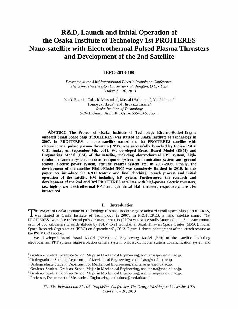
Space Research Organization (ISRO) on September 9th, 2012. Figure 1 shows photographs of the launch feature of
the PSLV C-21 rocket.
We developed Bread Board Model (BBM) and Engineering Model (EM) of the satellite, including
electrothermal PPT system, high-resolution camera system, onboard-computer system, communication system and
1 Graduate Student, Graduate School Major in Mechanical Engineering, and [email protected].
2 Undergraduate Student, Department of Mechanical Engineering, and [email protected].
3 Undergraduate Student, Department of Mechanical Engineering, and [email protected].
4 Graduate Student, Graduate School Major in Mechanical Engineering, and [email protected].
5 Graduate Student, Graduate School Major in Mechanical Engineering, and [email protected].
6 Professor, Department of Mechanical Engineering, and [email protected].
T
The 33st International Electric Propulsion Conference, The George Washington University, USA
October 6 – 10, 2013
2
ground station, electric power system, attitude control system etc, in 2007-2009. Finally, the development of the
satellite Flight-Model (FM) was completely finished in 2010. The satellite’s main mission are to achieve powered
flight of nano-satellite by an electric thruster and to observe Kansai district in Japan with a high-resolution camera.
In this paper, we introduce the R&D feature and final checking, launch process and initial operation of the
satellite FM including EP system. Furthermore, the research and development of the 2nd and 3rd PROITERES
satellites with high-power electric thrusters, i.e., high-power electrothermal PPT and cylindrical Hall thruster,
respectively, are also introduced.
Figure 1. Launch of PSLV C-21 rocket.
(Photo Courtesy of ISRO)
II. Overview of the 1st PROITERES
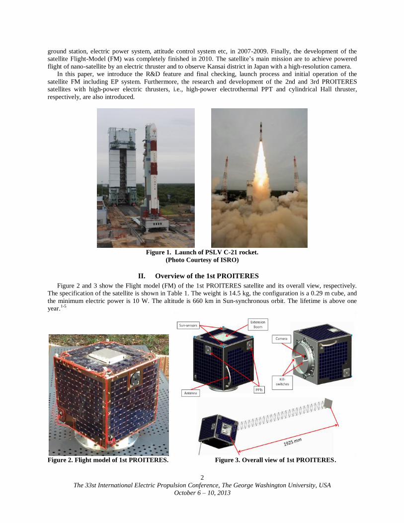
Figure 2 and 3 show the Flight model (FM) of the 1st PROITERES satellite and its overall view, respectively.
The specification of the satellite is shown in Table 1. The weight is 14.5 kg, the configuration is a 0.29 m cube, and
the minimum electric power is 10 W. The altitude is 660 km in Sun-synchronous orbit. The lifetime is above one
year.1-5
Figure 2. Flight model of 1st PROITERES. Figure 3. Overall view of 1st PROITERES.
The 33st International Electric Propulsion Conference, The George Washington University, USA
October 6 – 10, 2013
3
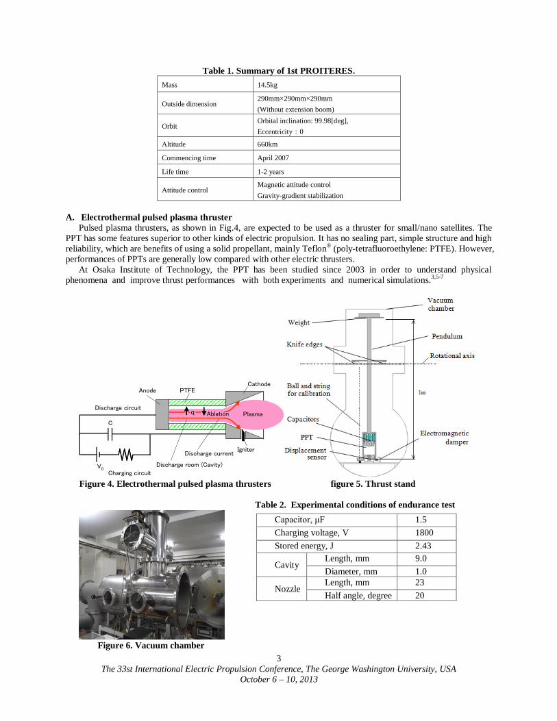
Table 1. Summary of 1st PROITERES.
Mass 14.5kg
Outside dimension 290mm×290mm×290mm
(Without extension boom)
Orbit Orbital inclination: 99.98[deg],
Eccentricity:0
Altitude 660km
Commencing time April 2007
Life time 1-2 years
Attitude control Magnetic attitude control
Gravity-gradient stabilization
A. Electrothermal pulsed plasma thruster
Pulsed plasma thrusters, as shown in Fig.4, are expected to be used as a thruster for small/nano satellites. The
PPT has some features superior to other kinds of electric propulsion. It has no sealing part, simple structure and high
reliability, which are benefits of using a solid propellant, mainly Teflon® (poly-tetrafluoroethylene: PTFE). However,
performances of PPTs are generally low compared with other electric thrusters.
At Osaka Institute of Technology, the PPT has been studied since 2003 in order to understand physical
phenomena and improve thrust performances with both experiments and numerical simulations.3,5-7
C
PTFECathode
Anode
Plasma
V0
Ablationq
IgniterDischarge current
Charging circuit
Discharge circuit
Discharge room (Cavity)
Figure 4. Electrothermal pulsed plasma thrusters figure 5. Thrust stand
Table 2. Experimental conditions of endurance test
Figure 6. Vacuum chamber
Capacitor, μF 1.5
Charging voltage, V 1800
Stored energy, J 2.43
Cavity Length, mm 9.0
Diameter, mm 1.0
Nozzle Length, mm 23
Half angle, degree 20
The 33st International Electric Propulsion Conference, The George Washington University, USA
October 6 – 10, 2013
4
We mainly studied electrothermal-acceleration-type PPTs, which generally had higher thrust-to-power ratios
(impulse bit per unit initial energy stored in capacitors) and higher thrust efficiencies than electromagnetic-
acceleration-type PPTs. Although the electrothermal PPT has lower specific impulse than the electromagnetic PPT,
the low specific impulse is not a significant problem as long as the PPT uses solid propellant, because there is no
tank nor valve for liquid or gas propellant which would be a large weight proportion of a thruster system.
In our study, the length and diameter of a Teflon discharge room of electrothermal PPTs were changed to find
the optimum configuration of PPT heads in very low energy operations for PROITERES satellite. Initial impulse bit
measurements were conducted, and long operations and endurance tests were also carried out with the optimum
PPT configuration. Figure 5 shows a thrust stand in a vacuum chamber for precise measurement of an impulse bit.
The PPT and capacitors are mounted on the pendulum, which rotates around fulcrums of two knife edges without
friction. The displacement of the pendulum is detected by an eddy-current-type gap sensor (non-contacting micro-
displacement meter) near the PPT, which resolution is about ±0.5 m.
Figure 6 shows a vacuum chamber 1.25 m in length and 0.6 m in inner diameter, which is evacuated using a
turbo-molecular pump with a pumping speed of 3,000 l/s. The pressure is kept below 1.0x10⁻²
Pa during PPT
operation. We carried out endurance tests with the optimum cavity shape 9.0 mm in length and 1.0 mm in diameter
at a discharge energy per one shot of 2.43 J/s. Table 2 shows the operational condition of endurance test. The
repetitive frequency is 1.0 Hz.
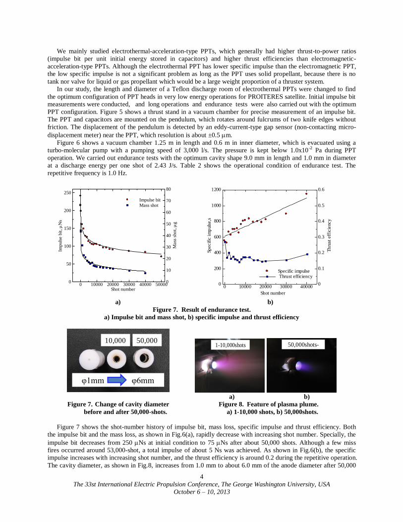
a) b)
Figure 7. Result of endurance test.
a) Impulse bit and mass shot, b) specific impulse and thrust efficiency
50,00010,000
φ1mm φ6mm
1-10,000shots
50,000shots-
a) b)
Figure 7. Change of cavity diameter Figure 8. Feature of plasma plume.
before and after 50,000-shots. a) 1-10,000 shots, b) 50,000shots.
Figure 7 shows the shot-number history of impulse bit, mass loss, specific impulse and thrust efficiency. Both
the impulse bit and the mass loss, as shown in Fig.6(a), rapidly decrease with increasing shot number. Specially, the
impulse bit decreases from 250 Ns at initial condition to 75 Ns after about 50,000 shots. Although a few miss
fires occurred around 53,000-shot, a total impulse of about 5 Ns was achieved. As shown in Fig.6(b), the specific
impulse increases with increasing shot number, and the thrust efficiency is around 0.2 during the repetitive operation.
The cavity diameter, as shown in Fig.8, increases from 1.0 mm to about 6.0 mm of the anode diameter after 50,000
Imp
uls
e b
it,
s
Shot number
Mass
sho
t,
g
Impulse bit Mass shot
0 10000 20000 30000 40000 500000
50
100
150
200
250
0
10
20
30
40
50
60
70
80
Sp
ecif
ic i
mp
uls
e,s
Th
rust
eff
icie
ncy
Shot number
Specific impulse Thrust efficiency
0 10000 20000 30000 400000
200
400
600
800
1000
1200
0
0.1
0.2
0.3
0.4
0.5
0.6
The 33st International Electric Propulsion Conference, The George Washington University, USA
October 6 – 10, 2013
5
shots. The discharge feature, as shown in Fig.9, changes from a long plasma plume with intensive emission light at
1-10,000 shots to a very short plume with weak emission. This is expected because of lowing pressure and
ionization degree in the cavity when enlarging cavity diameter.
PTFE
Cathode: SUS304
Anode: Copper
Body: Polycarbonate
Holder: Polycarbonate
Power Processing Unit
Capacitor
a) b)
Figure 9. Inner structure of PPT. Figure 10. PPT flight-model parts.
a) Photos of PPT head, b) power processing unit
and 1.5-F capacitor of flight model of PPT.
We designed the flight model of a PPT head and its system. Figure 9 and 10 show the structure, illustrations, and
photos. The PPT head has a simple structure, and two PPT heads are settled on the outer plate of PROITERES
satellite. As shown in Fig.10(b), the power processing unit and the 1.5-F capacitor are mounted in the satellite. The
final endurance test of the PPT system was successfully finished.6-8
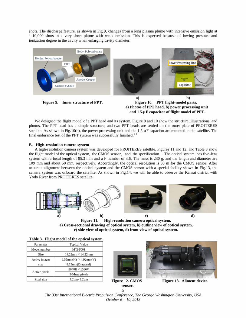
B. High-resolution camera system
A high-resolution camera system was developed for PROITERES satellite. Figures 11 and 12, and Table 3 show
the flight model of the optical system, the CMOS sensor, and the specification. The optical system has five-lens
system with a focal length of 85.3 mm and a F number of 3.6. The mass is 230 g, and the length and diameter are
109 mm and about 50 mm, respectively. Accordingly, the optical resolution is 30 m for the CMOS sensor. After
accurate alignment between the optical system and the CMOS sensor with a special facility shown in Fig.13, the
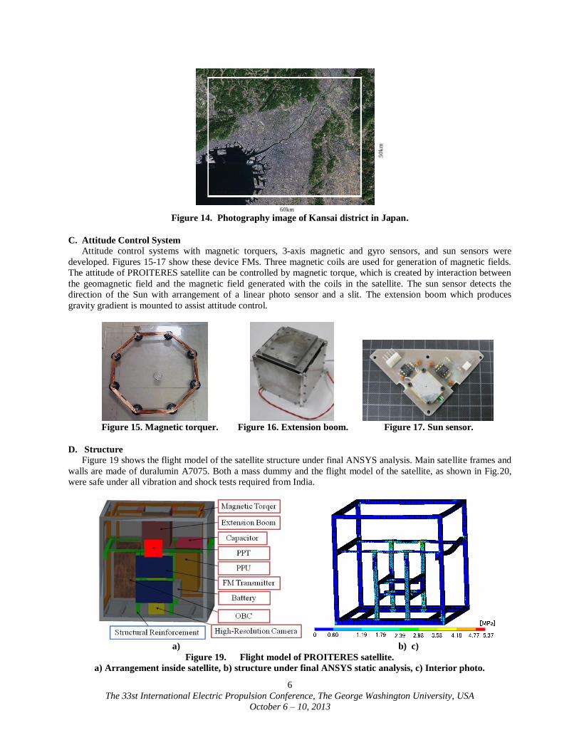
camera system was onboard the satellite. As shown in Fig.14, we will be able to observe the Kansai district with
Yodo River from PROITERES satellite.
a) b) c) d)
Figure 11. High-resolution camera optical system.
a) Cross-sectional drawing of optical system, b) outline view of optical system,
c) side view of optical system, d) front view of optical system.
Table 3. Flight model of the optical system.
Figure 12. CMOS Figure 13. Aliment device.
sensor.
Parameter Typical Value
Model number MT9T001
Size 14.22mm×14.22mm
Active imager
size
6.55mm(H) ×4.92mm(V)
8.19mm(Diagonal)
Active pixels 2048H×1536V
3-Mega pixels
Pixel size 3.2μm×3.2μm
The 33st International Electric Propulsion Conference, The George Washington University, USA
October 6 – 10, 2013
6
50
km
60km Figure 14. Photography image of Kansai district in Japan.
C. Attitude Control System
Attitude control systems with magnetic torquers, 3-axis magnetic and gyro sensors, and sun sensors were
developed. Figures 15-17 show these device FMs. Three magnetic coils are used for generation of magnetic fields.
The attitude of PROITERES satellite can be controlled by magnetic torque, which is created by interaction between
the geomagnetic field and the magnetic field generated with the coils in the satellite. The sun sensor detects the
direction of the Sun with arrangement of a linear photo sensor and a slit. The extension boom which produces
gravity gradient is mounted to assist attitude control.
Figure 15. Magnetic torquer. Figure 16. Extension boom. Figure 17. Sun sensor.
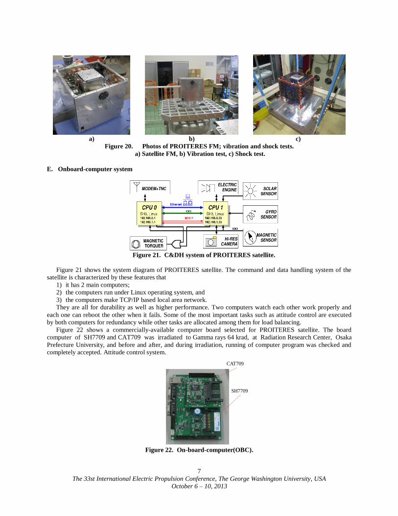
D. Structure
Figure 19 shows the flight model of the satellite structure under final ANSYS analysis. Main satellite frames and
walls are made of duralumin A7075. Both a mass dummy and the flight model of the satellite, as shown in Fig.20,
were safe under all vibration and shock tests required from India.
a) b) c)
Figure 19. Flight model of PROITERES satellite.
a) Arrangement inside satellite, b) structure under final ANSYS static analysis, c) Interior photo.
The 33st International Electric Propulsion Conference, The George Washington University, USA
October 6 – 10, 2013
7
a) b) c)
Figure 20. Photos of PROITERES FM; vibration and shock tests.
a) Satellite FM, b) Vibration test, c) Shock test.
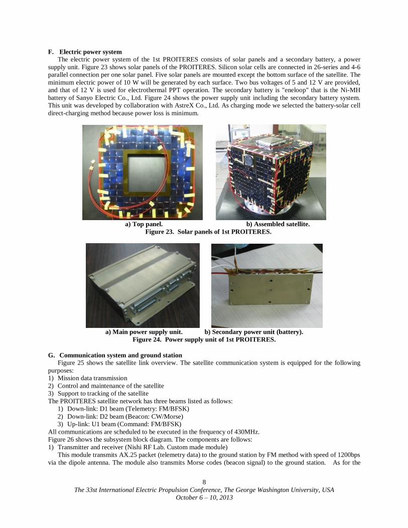
E. Onboard-computer system
Figure 21. C&DH system of PROITERES satellite.
Figure 21 shows the system diagram of PROITERES satellite. The command and data handling system of the
satellite is characterized by these features that
1) it has 2 main computers;
2) the computers run under Linux operating system, and
3) the computers make TCP/IP based local area network.
They are all for durability as well as higher performance. Two computers watch each other work properly and
each one can reboot the other when it fails. Some of the most important tasks such as attitude control are executed
by both computers for redundancy while other tasks are allocated among them for load balancing.
Figure 22 shows a commercially-available computer board selected for PROITERES satellite. The board
computer of SH7709 and CAT709 was irradiated to Gamma rays 64 krad, at Radiation Research Center, Osaka
Prefecture University, and before and after, and during irradiation, running of computer program was checked and
completely accepted. Attitude control system.
Figure 22. On-board-computer(OBC).
CAT709
SH7709
The 33st International Electric Propulsion Conference, The George Washington University, USA
October 6 – 10, 2013
8
F. Electric power system
The electric power system of the 1st PROITERES consists of solar panels and a secondary battery, a power
supply unit. Figure 23 shows solar panels of the PROITERES. Silicon solar cells are connected in 26-series and 4-6
parallel connection per one solar panel. Five solar panels are mounted except the bottom surface of the satellite. The
minimum electric power of 10 W will be generated by each surface. Two bus voltages of 5 and 12 V are provided,
and that of 12 V is used for electrothermal PPT operation. The secondary battery is "eneloop" that is the Ni-MH
battery of Sanyo Electric Co., Ltd. Figure 24 shows the power supply unit including the secondary battery system.
This unit was developed by collaboration with AstreX Co., Ltd. As charging mode we selected the battery-solar cell
direct-charging method because power loss is minimum.
a) Top panel. b) Assembled satellite.
Figure 23. Solar panels of 1st PROITERES.
a) Main power supply unit. b) Secondary power unit (battery).
Figure 24. Power supply unit of 1st PROITERES.
G. Communication system and ground station
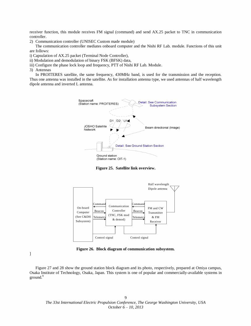
Figure 25 shows the satellite link overview. The satellite communication system is equipped for the following
purposes:
1) Mission data transmission
2) Control and maintenance of the satellite
3) Support to tracking of the satellite
The PROITERES satellite network has three beams listed as follows:
1) Down-link: D1 beam (Telemetry: FM/BFSK)
2) Down-link: D2 beam (Beacon: CW/Morse)
3) Up-link: U1 beam (Command: FM/BFSK)
All communications are scheduled to be executed in the frequency of 430MHz.
Figure 26 shows the subsystem block diagram. The components are follows:
1) Transmitter and receiver (Nishi RF Lab. Custom made module)
This module transmits AX.25 packet (telemetry data) to the ground station by FM method with speed of 1200bps
via the dipole antenna. The module also transmits Morse codes (beacon signal) to the ground station. As for the
The 33st International Electric Propulsion Conference, The George Washington University, USA
October 6 – 10, 2013
9
receiver function, this module receives FM signal (command) and send AX.25 packet to TNC in communication
controller.
2) Communication controller (UNISEC Custom made module)
The communication controller mediates onboard computer and the Nishi RF Lab. module. Functions of this unit
are follows:
i) Capsulation of AX.25 packet (Terminal Node Controller),
ii) Modulation and demodulation of binary FSK (BFSK) data,
iii) Configure the phase lock loop and frequency, PTT of Nishi RF Lab. Module.
3) Antennas
In PROITERES satellite, the same frequency, 430MHz band, is used for the transmission and the reception.
Thus one antenna was installed in the satellite. As for installation antenna type, we used antennas of half wavelength
dipole antenna and inverted L antenna.
Figure 25. Satellite link overview.
On-board
Computer
(See C&DH
Subsystem)
Communication
Controller
(TNC, FSK mod
& demod)
FM and CW
Transmitter
& FM
Receiver
Half wavelength
Dipole antenna
Command
Control signal
Command
Beacon Beacon
Telemetry Telemetry
Control signal
Figure 26. Block diagram of communication subsystem.
]
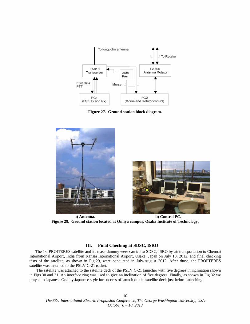
Figure 27 and 28 show the ground station block diagram and its photo, respectively, prepared at Omiya campus,
Osaka Institute of Technology, Osaka, Japan. This system is one of popular and commercially-available systems in
ground.9
The 33st International Electric Propulsion Conference, The George Washington University, USA
October 6 – 10, 2013
10
Figure 27. Ground station block diagram.
a) Antenna. b) Control PC.
Figure 28. Ground station located at Omiya campus, Osaka Institute of Technology.
III. Final Checking at SDSC, ISRO
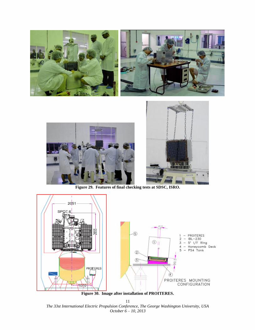
The 1st PROITERES satellite and its mass-dummy were carried to SDSC, ISRO by air transportation to Chennai
International Airport, India from Kansai International Airport, Osaka, Japan on July 18, 2012, and final checking
tests of the satellite, as shown in Fig.29, were conducted in July-August 2012. After those, the PROPTERES
satellite was installed to the PSLV C-21 rocket.
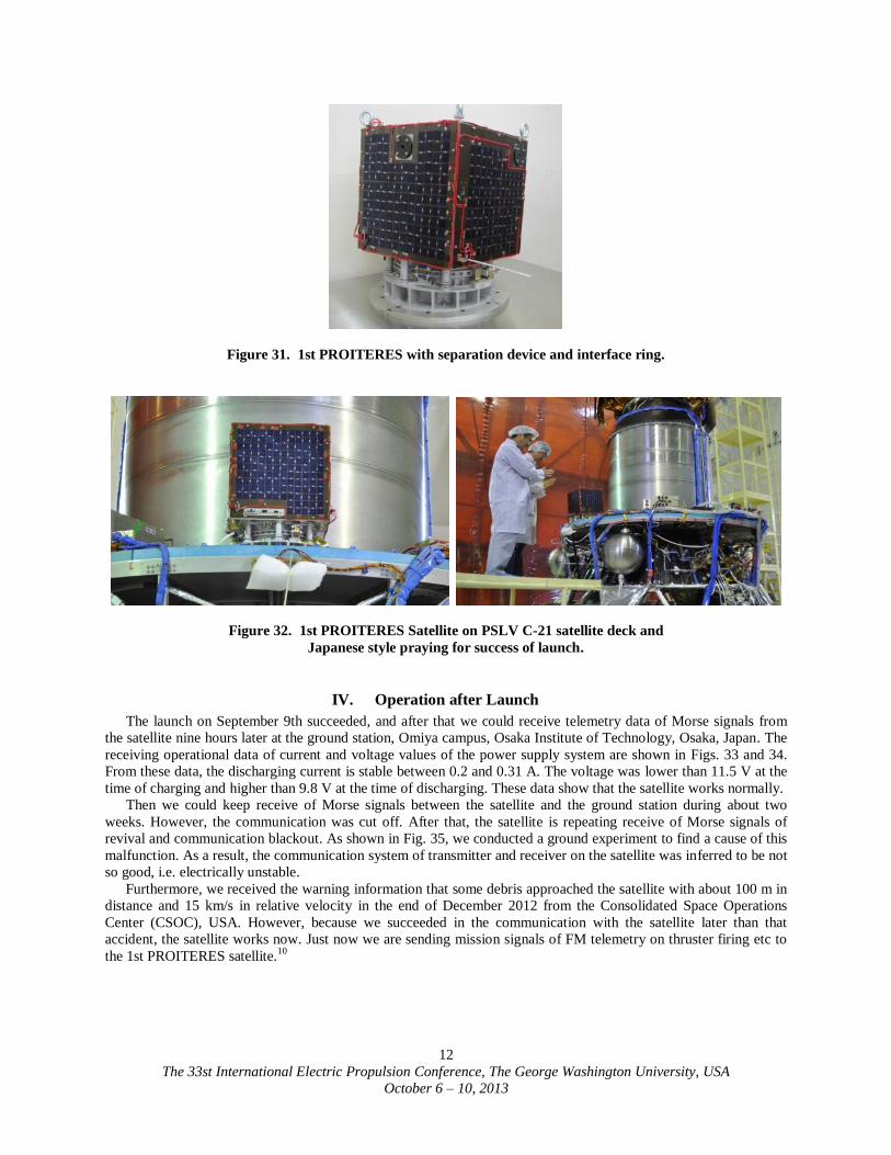
The satellite was attached to the satellite deck of the PSLV C-21 launcher with five degrees in inclination shown
in Figs.30 and 31. An interface ring was used to give an inclination of five degrees. Finally, as shown in Fig.32 we
prayed to Japanese God by Japanese style for success of launch on the satellite deck just before launching.
The 33st International Electric Propulsion Conference, The George Washington University, USA
October 6 – 10, 2013
11
Figure 29. Features of final checking tests at SDSC, ISRO.
Figure 30. Image after installation of PROITERES.
The 33st International Electric Propulsion Conference, The George Washington University, USA
October 6 – 10, 2013
12
Figure 31. 1st PROITERES with separation device and interface ring.
Figure 32. 1st PROITERES Satellite on PSLV C-21 satellite deck and
Japanese style praying for success of launch.
IV. Operation after Launch
The launch on September 9th succeeded, and after that we could receive telemetry data of Morse signals from
the satellite nine hours later at the ground station, Omiya campus, Osaka Institute of Technology, Osaka, Japan. The
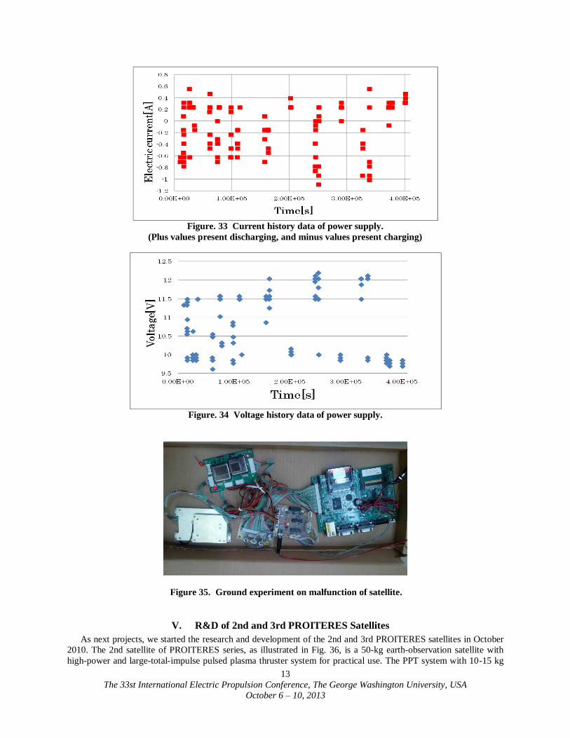
receiving operational data of current and voltage values of the power supply system are shown in Figs. 33 and 34.
From these data, the discharging current is stable between 0.2 and 0.31 A. The voltage was lower than 11.5 V at the
time of charging and higher than 9.8 V at the time of discharging. These data show that the satellite works normally.
Then we could keep receive of Morse signals between the satellite and the ground station during about two
weeks. However, the communication was cut off. After that, the satellite is repeating receive of Morse signals of
revival and communication blackout. As shown in Fig. 35, we conducted a ground experiment to find a cause of this
malfunction. As a result, the communication system of transmitter and receiver on the satellite was inferred to be not
so good, i.e. electrically unstable.
Furthermore, we received the warning information that some debris approached the satellite with about 100 m in
distance and 15 km/s in relative velocity in the end of December 2012 from the Consolidated Space Operations
Center (CSOC), USA. However, because we succeeded in the communication with the satellite later than that
accident, the satellite works now. Just now we are sending mission signals of FM telemetry on thruster firing etc to
the 1st PROITERES satellite.10
The 33st International Electric Propulsion Conference, The George Washington University, USA
October 6 – 10, 2013
13
Figure. 33 Current history data of power supply.
(Plus values present discharging, and minus values present charging)
Figure. 34 Voltage history data of power supply.
Figure 35. Ground experiment on malfunction of satellite.
V. R&D of 2nd and 3rd PROITERES Satellites
As next projects, we started the research and development of the 2nd and 3rd PROITERES satellites in October
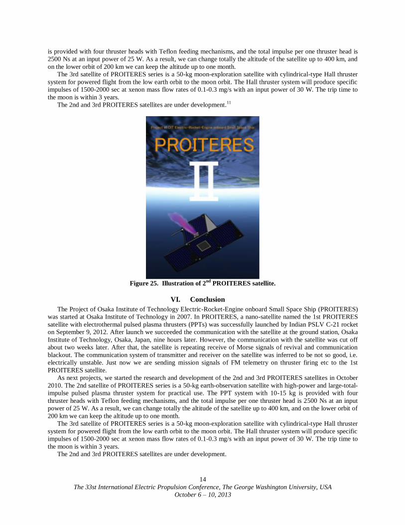
2010. The 2nd satellite of PROITERES series, as illustrated in Fig. 36, is a 50-kg earth-observation satellite with
high-power and large-total-impulse pulsed plasma thruster system for practical use. The PPT system with 10-15 kg
The 33st International Electric Propulsion Conference, The George Washington University, USA
October 6 – 10, 2013
14
is provided with four thruster heads with Teflon feeding mechanisms, and the total impulse per one thruster head is
2500 Ns at an input power of 25 W. As a result, we can change totally the altitude of the satellite up to 400 km, and
on the lower orbit of 200 km we can keep the altitude up to one month.
The 3rd satellite of PROITERES series is a 50-kg moon-exploration satellite with cylindrical-type Hall thruster
system for powered flight from the low earth orbit to the moon orbit. The Hall thruster system will produce specific
impulses of 1500-2000 sec at xenon mass flow rates of 0.1-0.3 mg/s with an input power of 30 W. The trip time to
the moon is within 3 years.
The 2nd and 3rd PROITERES satellites are under development.11
Figure 25. Illustration of 2
nd PROITERES satellite.
VI. Conclusion
The Project of Osaka Institute of Technology Electric-Rocket-Engine onboard Small Space Ship (PROITERES)
was started at Osaka Institute of Technology in 2007. In PROITERES, a nano-satellite named the 1st PROITERES
satellite with electrothermal pulsed plasma thrusters (PPTs) was successfully launched by Indian PSLV C-21 rocket
on September 9, 2012. After launch we succeeded the communication with the satellite at the ground station, Osaka
Institute of Technology, Osaka, Japan, nine hours later. However, the communication with the satellite was cut off
about two weeks later. After that, the satellite is repeating receive of Morse signals of revival and communication
blackout. The communication system of transmitter and receiver on the satellite was inferred to be not so good, i.e.
electrically unstable. Just now we are sending mission signals of FM telemetry on thruster firing etc to the 1st
PROITERES satellite.
As next projects, we started the research and development of the 2nd and 3rd PROITERES satellites in October
2010. The 2nd satellite of PROITERES series is a 50-kg earth-observation satellite with high-power and large-total-
impulse pulsed plasma thruster system for practical use. The PPT system with 10-15 kg is provided with four
thruster heads with Teflon feeding mechanisms, and the total impulse per one thruster head is 2500 Ns at an input
power of 25 W. As a result, we can change totally the altitude of the satellite up to 400 km, and on the lower orbit of
200 km we can keep the altitude up to one month.
The 3rd satellite of PROITERES series is a 50-kg moon-exploration satellite with cylindrical-type Hall thruster
system for powered flight from the low earth orbit to the moon orbit. The Hall thruster system will produce specific
impulses of 1500-2000 sec at xenon mass flow rates of 0.1-0.3 mg/s with an input power of 30 W. The trip time to
the moon is within 3 years.
The 2nd and 3rd PROITERES satellites are under development.

The 33st International Electric Propulsion Conference, The George Washington University, USA
October 6 – 10, 2013
15
References 1 Ikeda, T., Yamada, M., Shimizu, M., Fujiwara, T., Tahara, H., and Satellite R&D Team of Students and Faculty Members
of OIT,” Research and Development of an Attitude Control System for Osaka Institute of Technology Electric-Rocket-Engine
onboard Small Space Ship,” 27th International Symposium on Space Technology and Science, Tsukuba, Japan, 2009, Paper No. ISTS 2009-s-02f.
2 Yamada, M., Ikeda, T., Shimizu, M., Fujiwara, T. Tahara, H., and Satellite R&D Team of Students and Faculty Members of
OIT,” Progress of Project of Osaka Institute of Technology Electric-Rocket-Engine onboard Small Space Ship,” 27th
International Symposium on Space Technology and Science, Tsukuba, Japan, 2009, Paper No. ISTS 2009-s-05f. 3 Yamada, M, Ikeda, T, Fujiwara, T, and Tahara, H,” Project of Osaka Institute of Technology Electric-Rocket-Engine
onboard Small Space Ship,” 31st International Electric Propulsion Conference, University of Michigan, Ann Arbor, Michigan,
USA, 2009, Paper No. IEPC-2009-051. 4 Takagi, H., Yamamoto, T., Ishii, Y., and Tahara, H,“ Performance Enhancement of Electrothermal Pulsed Plasma Thrusters
for Osaka Institute of Technology Electric-Rocket-Engine onboard Small Space Ship,” 31st International Electric Propulsion
Conference, University of Michigan, Ann Arbor, Michigan, USA, 2009, Paper No. IEPC-2009-254. 5 Ozaki, J., Ikeda, T., Fujiwara, T., Nishizawa, M., Araki, S., Tahara, H., and Watanabe, Y.,” Development of Osaka Institute
of Technology Nano-Satellite “PROITERES” with Electrothermal Pulsed Plasma Thrusters,” 32nd International Electric Propulsion Conference, Kurhaus, Wiesbaden, Germany, 2011, Paper No. IEPC-2011-035.
6 Naka, M., Hosotani, R., Tahara, H., and Watanabe, Y,” Development of Electrothermal Pulsed Plasma Thruster System
Flight-Model for the PROITERES Satellite,” 32nd International Electric Propulsion Conference, Kurhaus, Wiesbaden, Germany,
2011, Paper No. IEPC-2011-034. 7 Tahara, H., Ishii, Y., Tanaka, M., Naka, M., and Watanabe, Y,” Flowfield Calculation of Electrothermal Pulsed Plasma
Thrusters for the PROITERES Satellite,” 32nd International Electric Propulsion Conference, Kurhaus, Wiesbaden, Germany,
2011, Paper No. IEPC-2011-037. 8 Kisaki, S., Ikeda, T., Inoue, Y., Egami, N, and Tahara, H.,” Development of Highly-Functional Nano/Small Satellites with
Pulsed Plasma Engines,” International Conference on Renewable Energy Research and Applications, Best Western Premier Hotel
Nagasaki, Nagasaki-City, Nagasaki, Japan, 2012. 9 Egami, N., Inoue, Y., Nakano, S., Ikeda, T., and Tahara,, H.,” Research and Development of Nano-Satellite PROITERES
with Electric Rocket Engines at Osaka Institute of Technology,” 8th IEEE Vehicle Power and Propulsion Conference, Olympic Parktel, Seoul, Korea, 2012, Paper No. SS01-0298.
10 Egami, N., Matsumoto, T., Sakamoto, M., Inoue, Y., Ikeda, T., and Tahara, H..” R&D, Launch and Initial Operation of the
Osaka Institute of Technology 1st PROITERES Nano-Satellite and Development of the 2nd and 3rd Satellites,” 29th
International Symposium on Space Technology and Science, Nagoya Congress Center, Nagoya-City, Aichi, Japan, 2013, Paper No. ISTS 2013-f-12.
11 Kamimura, T., Yamasaki, K., Egami, N., Matsumoto, T., Sakamoto, M., Inoue, Y., Ikeda, T., and Tahara, H.,” Final
Checking Process and Launch of the Osaka Institute of Technology 1st PROITERES Nano-Satellite Using Indian PSLV Rocket
C-21,” 29th International Symposium on Space Technology and Science, Nagoya Congress Center, Nagoya-City, Aichi, Japan, 2013, Paper No. ISTS 2013-f-48p.