Embed Size (px)
Citation preview
RCS User’s Guide
Ver.1.20
2
About M-5000 RCS 3
Online Mode/Offline Mode 4
Online Mode 4
Offline Mode 5
Compatible Operating Systems 6
Installing 7
Uninstalling 7
Starting the Program 7
Quitting the Program 7
Connecting to a Computer 8
Connection over a USB Cable from the USB COMPUTER Connector 8
Direct Connection over a Wired LAN or Wireless LAN 9
Connecting Using a LAN Cable 9
Connecting in Ad-hoc Mode 10
Connection over a Wired LAN or Wireless LAN via a Wireless LAN Router 11
Connecting the M-5000 and Wireless LAN Router Using a LAN Cable 11
Making a Wireless Connection Between the M-5000 and Wireless LAN Router 11
NETWORK Window 13
LAN SETUP Window 13
Connecting Using WPS 14
WIRELESS LAN AD-HOC SETUP Window 14
MIDI Window USB MIDI Tab 15
M-5000 RCS Operations 16
Main Window 16
Menus (Windows) 17
Menus (Mac) 17
Display Section 18
Fader Bank Section 18
Main Window Functions 19
Displaying More Than 8 Channels 19
Detaching Windows 20
Assignable Fader Section Window 21
User Assignable Section Window 21
Meter Bridge Window 21
Window Set 22
Saving a Window Set 22
Calling Up a Window Set 22
Editing the List of Window Sets 23
Shrinking the Display 24
Differences in Operation Between M-5000 RCS and the M-5000 26
Overall 26
When in the Online Mode 26
When in the Offline Mode 26
Contents
The explanations in this manual include illustrations that depict what should typically be shown by the display. Note, however, that your unit may incorporate a newer, enhanced version of the system, so what you actually see in the display may not always match what appears in the manual.Roland, REAC are either registered trademarks or trademarks of Roland Corporation in the United States and/or other countries.
Copyright © 2015 ROLAND CORPORATION
3
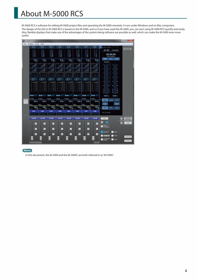
About M-5000 RCSM-5000 RCS is software for editing M-5000 project files and operating the M-5000 remotely. It runs under Windows and on Mac computers.The design of the GUI in M-5000 RCS is based on the M-5000, and so if you have used the M-5000, you can start using M-5000 RCS quickly and easily. Also, flexible displays that make use of the advantages of the system being software are possible as well, which can make the M-5000 even more useful.
Memo
In this document, the M-5000 and the M-5000C are both referred to as “M-5000.”
4
About M-5000 RCS
Online Mode/Offline Mode
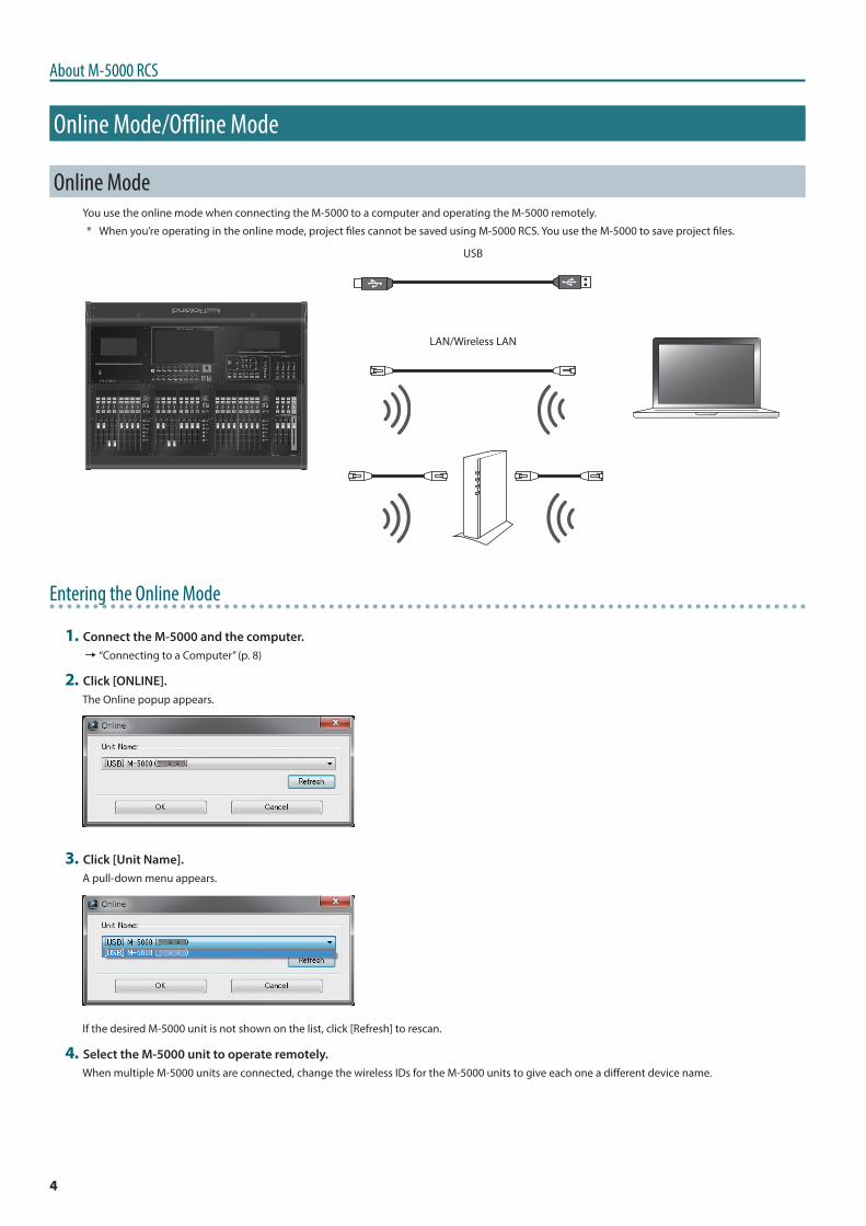
Online ModeYou use the online mode when connecting the M-5000 to a computer and operating the M-5000 remotely.
* When you’re operating in the online mode, project files cannot be saved using M-5000 RCS. You use the M-5000 to save project files.
USB
LAN/Wireless LAN
Entering the Online Mode
1 Connect the M-5000 and the computer.0“Connecting to a Computer” (p. 8)
2 Click [ONLINE].The Online popup appears.
3 Click [Unit Name].A pull-down menu appears.
If the desired M-5000 unit is not shown on the list, click [Refresh] to rescan.
4 Select the M-5000 unit to operate remotely.When multiple M-5000 units are connected, change the wireless IDs for the M-5000 units to give each one a different device name.
5
About M-5000 RCS
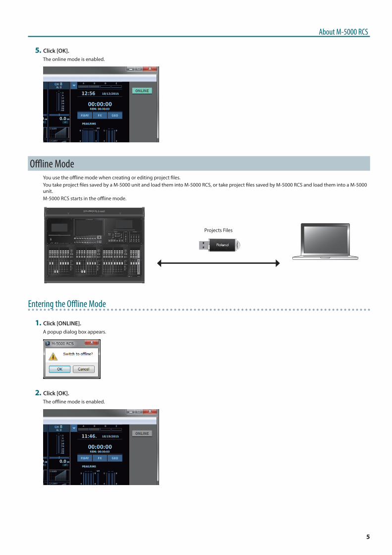
5 Click [OK].The online mode is enabled.
Offline ModeYou use the offline mode when creating or editing project files.You take project files saved by a M-5000 unit and load them into M-5000 RCS, or take project files saved by M-5000 RCS and load them into a M-5000 unit.M-5000 RCS starts in the offline mode.
Projects Files
Entering the Offline Mode
1 Click [ONLINE].A popup dialog box appears.
2 Click [OK].The offline mode is enabled.
6
About M-5000 RCS
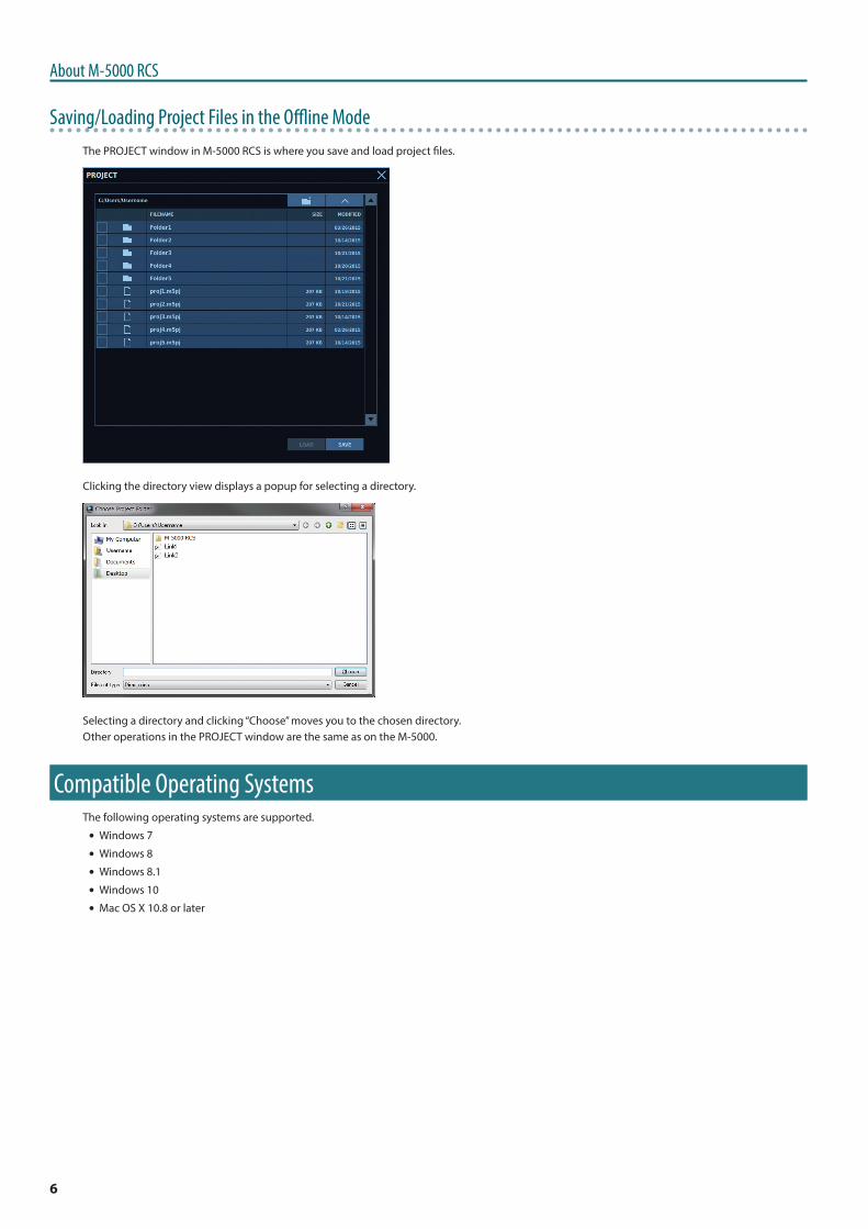
Saving/Loading Project Files in the Offline ModeThe PROJECT window in M-5000 RCS is where you save and load project files.
Clicking the directory view displays a popup for selecting a directory.
Selecting a directory and clicking “Choose” moves you to the chosen directory.Other operations in the PROJECT window are the same as on the M-5000.
Compatible Operating SystemsThe following operating systems are supported.
5 Windows 7
5 Windows 8
5 Windows 8.1
5 Windows 10
5 Mac OS X 10.8 or later
7
About M-5000 RCS
InstallingM-5000 RCS is available for download from the Roland website.http://proav roland com/
1 Copy the “M-5000 RCS” folder produced by expanding the archive file to the computer.
2 (Windows only) Install the font “DejaVu Sans Condensed Bold” inside the “fonts” folder onto the computer.Installing this font improves display in M-5000 RCS.
Installation Examples
5 Display Control Panel > Customize Desktop > Fonts. Drag “DejaVu Sans Condensed Bold” there.
5 Right-click “DejaVu Sans Condensed Bold,” then click “Install.”
5 Double-click “DejaVu San Condensed Bold” to display the Font Viewer. Click “Install.”For details, refer to the computer’s documentation.
Uninstalling1 Delete the “M-5000 RCS” folder from the computer.
Memo
The Window Set settings files are saved in the following directories.(Win) ~/AppData/Local/Roland/M-5000 RCS/Window Set/(Mac) ~/Library/Application Support/Roland/M-5000 RCS/Window Set/0“Window Set” (p. 22)
Starting the Program1 Go into the “M-5000 RCS” folder and double-click “M-5000 RCS.”
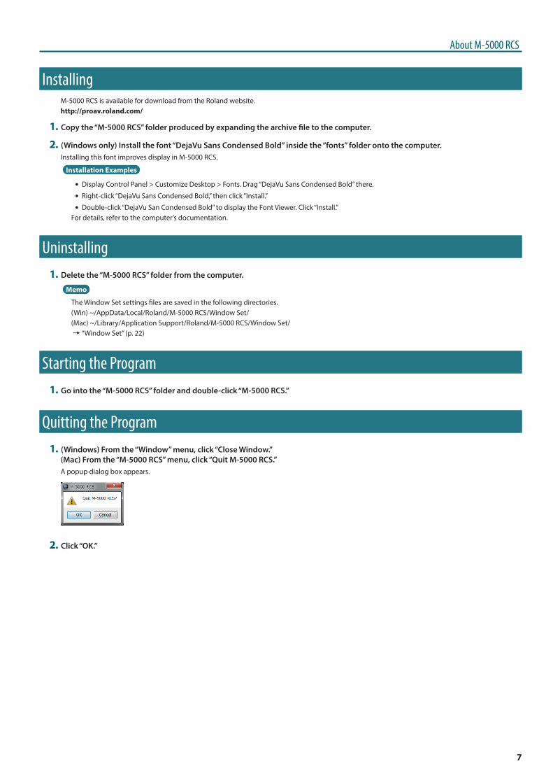
Quitting the Program1 (Windows) From the “Window” menu, click “Close Window.”
(Mac) From the “M-5000 RCS” menu, click “Quit M-5000 RCS.”A popup dialog box appears.
2 Click “OK.”
8
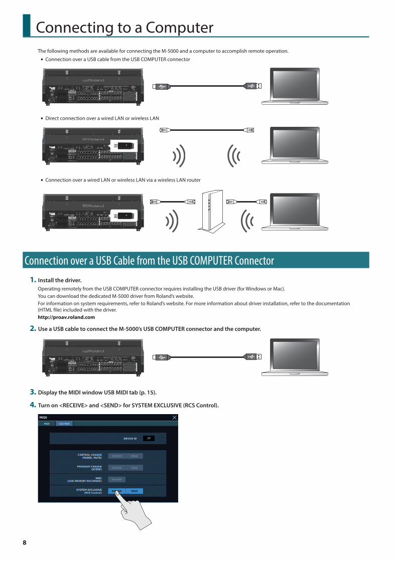
Connecting to a ComputerThe following methods are available for connecting the M-5000 and a computer to accomplish remote operation.
5 Connection over a USB cable from the USB COMPUTER connector
5 Direct connection over a wired LAN or wireless LAN
5 Connection over a wired LAN or wireless LAN via a wireless LAN router
Connection over a USB Cable from the USB COMPUTER Connector1 Install the driver.
Operating remotely from the USB COMPUTER connector requires installing the USB driver (for Windows or Mac).You can download the dedicated M-5000 driver from Roland’s website.For information on system requirements, refer to Roland’s website. For more information about driver installation, refer to the documentation (HTML file) included with the driver.http://proav roland com
2 Use a USB cable to connect the M-5000’s USB COMPUTER connector and the computer.
3 Display the MIDI window USB MIDI tab (p. 15).
4 Turn on <RECEIVE> and <SEND> for SYSTEM EXCLUSIVE (RCS Control).
9
Connecting to a Computer
Direct Connection over a Wired LAN or Wireless LAN
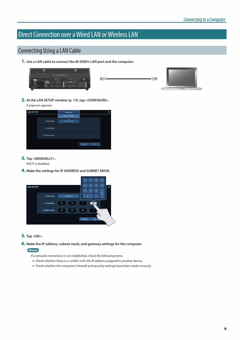
Connecting Using a LAN Cable1 Use a LAN cable to connect the M-5000’s LAN port and the computer.
2 At the LAN SETUP window (p. 13), tap <CONFIGURE>.A popover appears.
3 Tap <MANUALLY>.DHCP is disabled.
4 Make the settings for IP ADDRESS and SUBNET MASK.
5 Tap <OK>.
6 Make the IP address, subnet mask, and gateway settings for the computer.
Memo
If a network connection is not established, check the following items.
5 Check whether there is a conflict with the IP address assigned to another device.
5 Check whether the computer’s firewall and security settings have been made correctly.
10
Connecting to a Computer
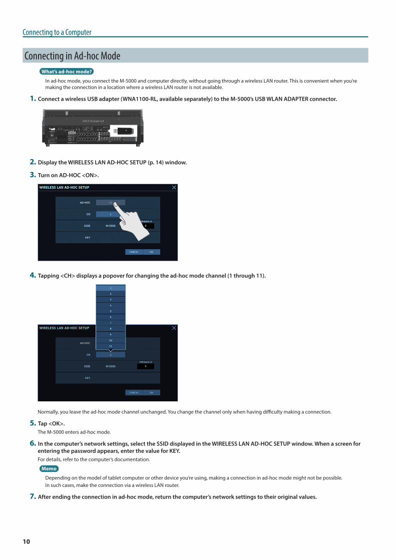
Connecting in Ad-hoc ModeWhat’s ad-hoc mode?
In ad-hoc mode, you connect the M-5000 and computer directly, without going through a wireless LAN router. This is convenient when you’re making the connection in a location where a wireless LAN router is not available.
1 Connect a wireless USB adapter (WNA1100-RL, available separately) to the M-5000’s USB WLAN ADAPTER connector.
2 Display the WIRELESS LAN AD-HOC SETUP (p. 14) window.
3 Turn on AD-HOC <ON>.
4 Tapping <CH> displays a popover for changing the ad-hoc mode channel (1 through 11).
Normally, you leave the ad-hoc mode channel unchanged. You change the channel only when having difficulty making a connection.
5 Tap <OK>.The M-5000 enters ad-hoc mode.
6 In the computer’s network settings, select the SSID displayed in the WIRELESS LAN AD-HOC SETUP window. When a screen for entering the password appears, enter the value for KEY.For details, refer to the computer’s documentation.
Memo
Depending on the model of tablet computer or other device you’re using, making a connection in ad-hoc mode might not be possible.In such cases, make the connection via a wireless LAN router.
7 After ending the connection in ad-hoc mode, return the computer’s network settings to their original values.
11
Connecting to a Computer
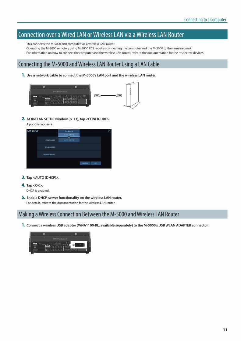
Connection over a Wired LAN or Wireless LAN via a Wireless LAN RouterThis connects the M-5000 and computer via a wireless LAN router.Operating the M-5000 remotely using M-5000 RCS requires connecting the computer and the M-5000 to the same network.For information on how to connect the computer and the wireless LAN router, refer to the documentation for the respective devices.
Connecting the M-5000 and Wireless LAN Router Using a LAN Cable1 Use a network cable to connect the M-5000’s LAN port and the wireless LAN router.
2 At the LAN SETUP window (p. 13), tap <CONFIGURE>.A popover appears.
3 Tap <AUTO (DHCP)>.
4 Tap <OK>.DHCP is enabled.
5 Enable DHCP-server functionality on the wireless LAN router.For details, refer to the documentation for the wireless LAN router.
Making a Wireless Connection Between the M-5000 and Wireless LAN Router1 Connect a wireless USB adapter (WNA1100-RL, available separately) to the M-5000’s USB WLAN ADAPTER connector.
12
Connecting to a Computer
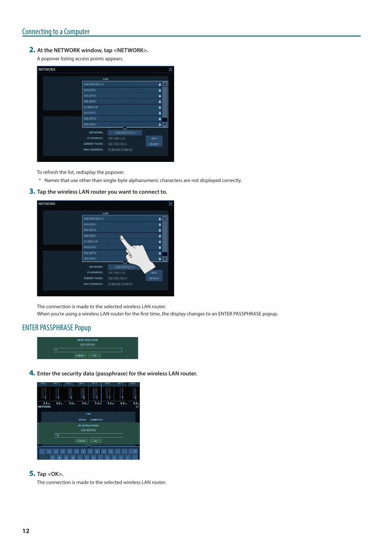
2 At the NETWORK window, tap <NETWORK>.A popover listing access points appears.
To refresh the list, redisplay the popover.
* Names that use other than single-byte alphanumeric characters are not displayed correctly.
3 Tap the wireless LAN router you want to connect to.
The connection is made to the selected wireless LAN router.When you’re using a wireless LAN router for the first time, the display changes to an ENTER PASSPHRASE popup.
ENTER PASSPHRASE Popup
4 Enter the security data (passphrase) for the wireless LAN router.
5 Tap <OK>.The connection is made to the selected wireless LAN router.
13
Connecting to a Computer
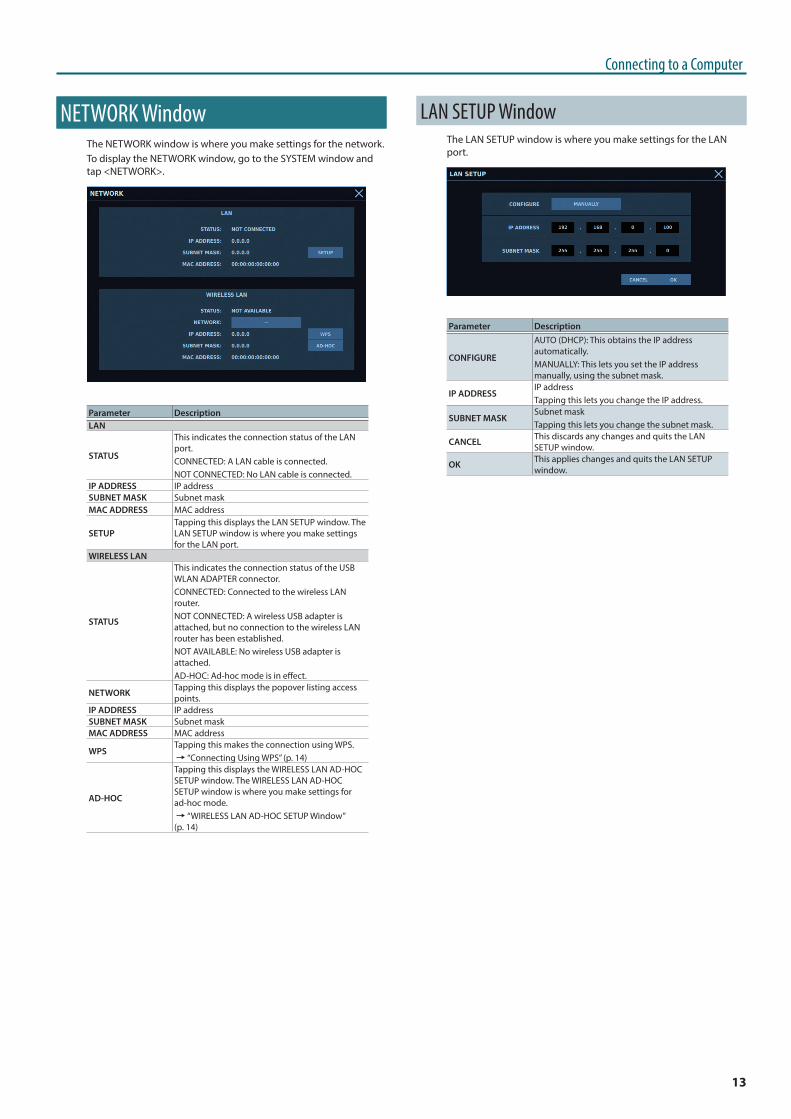
NETWORK WindowThe NETWORK window is where you make settings for the network.To display the NETWORK window, go to the SYSTEM window and tap <NETWORK>.
Parameter DescriptionLAN
STATUS
This indicates the connection status of the LAN port.CONNECTED: A LAN cable is connected.NOT CONNECTED: No LAN cable is connected.
IP ADDRESS IP addressSUBNET MASK Subnet maskMAC ADDRESS MAC address
SETUPTapping this displays the LAN SETUP window. The LAN SETUP window is where you make settings for the LAN port.
WIRELESS LAN
STATUS
This indicates the connection status of the USB WLAN ADAPTER connector.CONNECTED: Connected to the wireless LAN router.NOT CONNECTED: A wireless USB adapter is attached, but no connection to the wireless LAN router has been established.NOT AVAILABLE: No wireless USB adapter is attached.AD-HOC: Ad-hoc mode is in effect.
NETWORK Tapping this displays the popover listing access points.
IP ADDRESS IP addressSUBNET MASK Subnet maskMAC ADDRESS MAC address
WPSTapping this makes the connection using WPS.0“Connecting Using WPS” (p. 14)
AD-HOC
Tapping this displays the WIRELESS LAN AD-HOC SETUP window. The WIRELESS LAN AD-HOC SETUP window is where you make settings for ad-hoc mode.0“WIRELESS LAN AD-HOC SETUP Window” (p. 14)
LAN SETUP WindowThe LAN SETUP window is where you make settings for the LAN port.
Parameter Description
CONFIGURE
AUTO (DHCP): This obtains the IP address automatically.MANUALLY: This lets you set the IP address manually, using the subnet mask.
IP ADDRESSIP addressTapping this lets you change the IP address.
SUBNET MASKSubnet maskTapping this lets you change the subnet mask.
CANCEL This discards any changes and quits the LAN SETUP window.
OK This applies changes and quits the LAN SETUP window.
14
Connecting to a Computer
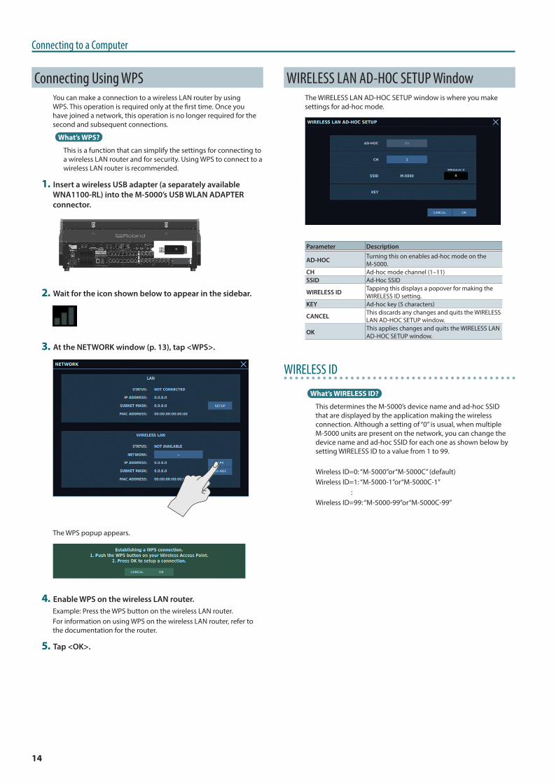
Connecting Using WPSYou can make a connection to a wireless LAN router by using WPS. This operation is required only at the first time. Once you have joined a network, this operation is no longer required for the second and subsequent connections.
What’s WPS?
This is a function that can simplify the settings for connecting to a wireless LAN router and for security. Using WPS to connect to a wireless LAN router is recommended.
1 Insert a wireless USB adapter (a separately available WNA1100-RL) into the M-5000’s USB WLAN ADAPTER connector.
2 Wait for the icon shown below to appear in the sidebar.
3 At the NETWORK window (p. 13), tap <WPS>.
The WPS popup appears.
4 Enable WPS on the wireless LAN router.Example: Press the WPS button on the wireless LAN router.For information on using WPS on the wireless LAN router, refer to the documentation for the router.
5 Tap <OK>.
WIRELESS LAN AD-HOC SETUP WindowThe WIRELESS LAN AD-HOC SETUP window is where you make settings for ad-hoc mode.
Parameter Description
AD-HOC Turning this on enables ad-hoc mode on the M-5000.
CH Ad-hoc mode channel (1–11)SSID Ad-Hoc SSID
WIRELESS ID Tapping this displays a popover for making the WIRELESS ID setting.
KEY Ad-hoc key (5 characters)
CANCEL This discards any changes and quits the WIRELESS LAN AD-HOC SETUP window.
OK This applies changes and quits the WIRELESS LAN AD-HOC SETUP window.
WIRELESS ID
What’s WIRELESS ID?
This determines the M-5000’s device name and ad-hoc SSID that are displayed by the application making the wireless connection. Although a setting of “0” is usual, when multiple M-5000 units are present on the network, you can change the device name and ad-hoc SSID for each one as shown below by setting WIRELESS ID to a value from 1 to 99.
Wireless ID=0: “M-5000”or“M-5000C” (default)Wireless ID=1: “M-5000-1”or“M-5000C-1” :Wireless ID=99: “M-5000-99”or“M-5000C-99”
15
Connecting to a Computer
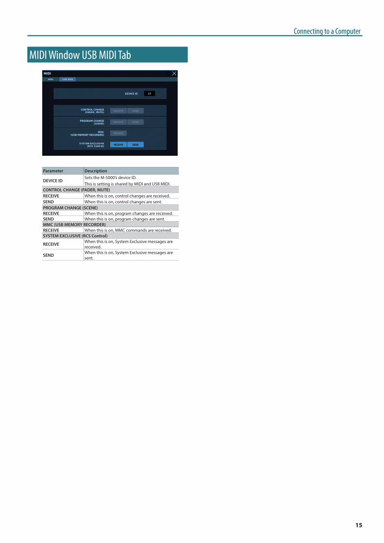
MIDI Window USB MIDI Tab
Parameter Description
DEVICE IDSets the M-5000’s device ID.This is setting is shared by MIDI and USB MIDI.
CONTROL CHANGE (FADER, MUTE)RECEIVE When this is on, control changes are received.SEND When this is on, control changes are sent.PROGRAM CHANGE (SCENE)RECEIVE When this is on, program changes are received.SEND When this is on, program changes are sent.MMC (USB MEMORY RECORDER)RECEIVE When this is on, MMC commands are received.SYSTEM EXCLUSIVE (RCS Control)
RECEIVE When this is on, System Exclusive messages are received.
SEND When this is on, System Exclusive messages are sent.
16
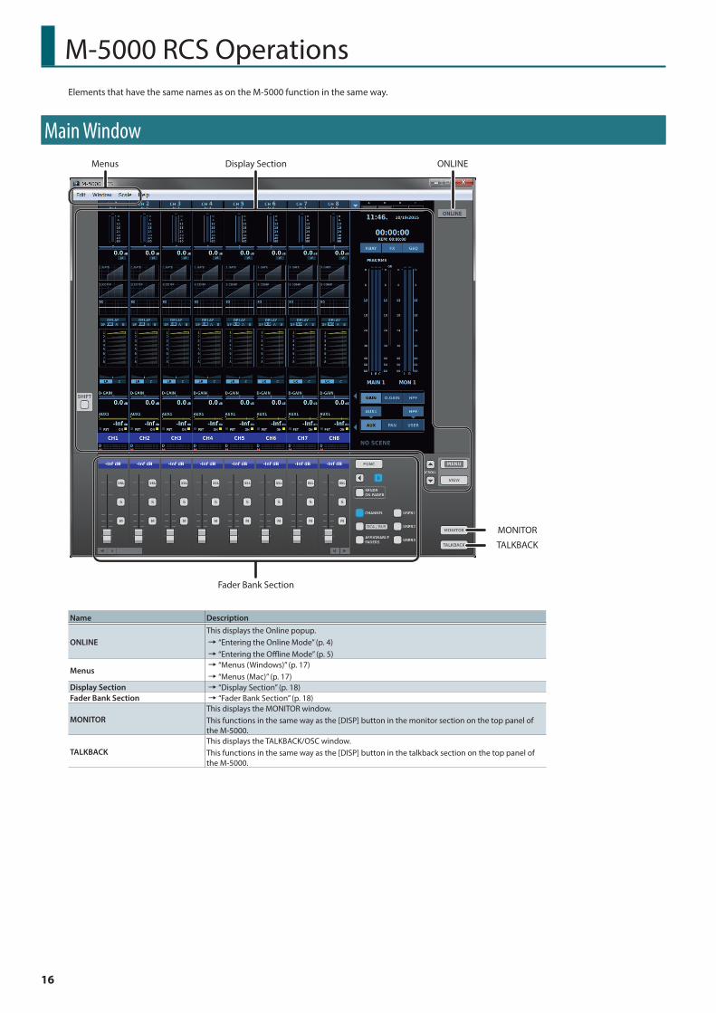
M-5000 RCS OperationsElements that have the same names as on the M-5000 function in the same way.
Main WindowMenus
Fader Bank Section
Display Section ONLINE
MONITOR
TALKBACK
Name Description
ONLINEThis displays the Online popup.0“Entering the Online Mode” (p. 4)0“Entering the Offline Mode” (p. 5)
Menus0“Menus (Windows)” (p. 17)0“Menus (Mac)” (p. 17)
Display Section 0“Display Section” (p. 18)Fader Bank Section 0“Fader Bank Section” (p. 18)
MONITORThis displays the MONITOR window.This functions in the same way as the [DISP] button in the monitor section on the top panel of the M-5000.
TALKBACKThis displays the TALKBACK/OSC window.This functions in the same way as the [DISP] button in the talkback section on the top panel of the M-5000.
17
M-5000 RCS Operations
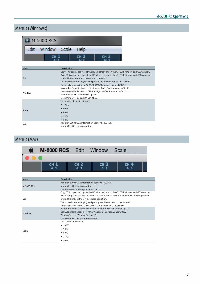
Menus (Windows)
Menu Description
Edit
Copy: This copies settings at the HOME screen and in the CH EDIT window and GEQ window.Paste: This pastes settings at the HOME screen and in the CH EDIT window and GEQ window.Undo: This undoes the last-executed operation.The procedures for copying and pasting are the same as on the M-5000.For details, refer to the “M-5000/M-5000C Reference Manual (PDF).”
Window
Assignable Fader Section: 0“Assignable Fader Section Window” (p. 21)User Assignable Section: 0“User Assignable Section Window” (p. 21)Window Set: 0“Window Set” (p. 22)Close Window: This quits M-5000 RCS.
Scale
This shrinks the main window.
5 100%
5 90%
5 80%
5 75%
5 50%
HelpAbout M-5000 RCS...: Information about M-5000 RCSAbout Qt...: License information
Menus (Mac)
Menu Description
M-5000 RCSAbout M-5000 RCS...: Information about M-5000 RCSAbout Qt...: License informationQuit M-5000 RCS: This quits M-5000 RCS.
Edit
Copy: This copies settings at the HOME screen and in the CH EDIT window and GEQ window.Paste: This pastes settings at the HOME screen and in the CH EDIT window and GEQ window.Undo: This undoes the last-executed operation.The procedures for copying and pasting are the same as on the M-5000.For details, refer to the “M-5000/M-5000C Reference Manual (PDF).”
Window
Assignable Fader Section: 0“Assignable Fader Section Window” (p. 21)User Assignable Section: 0“User Assignable Section Window” (p. 21)Window Set: 0“Window Set” (p. 22)Close Window: This closes the window.
Scale
This shrinks the window.
5 100%
5 90%
5 80%
5 75%
5 50%
18
M-5000 RCS Operations
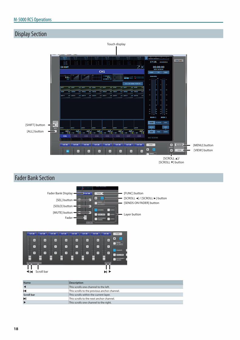
Display SectionTouch display
[MENU] button
[SHIFT] button
[VIEW] button
[ALL] button
[SCROLL H]/ [SCROLL I] button
Fader Bank Section
Fader Bank Display [FUNC] button
[SENDS ON FADER] button[SCROLL K] / [SCROLL J] button
Layer buttonFader
[SEL] button
[SOLO] button
[MUTE] button
C AScroll bar
Name DescriptionC This scrolls one channel to the left.
This scrolls to the previous anchor channel.Scroll bar This scrolls within the current layer.
This scrolls to the next anchor channel.A This scrolls one channel to the right.
19
M-5000 RCS Operations
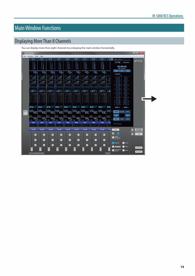
Main Window Functions
Displaying More Than 8 ChannelsYou can display more than eight channels by enlarging the main window horizontally.
0
20
M-5000 RCS Operations
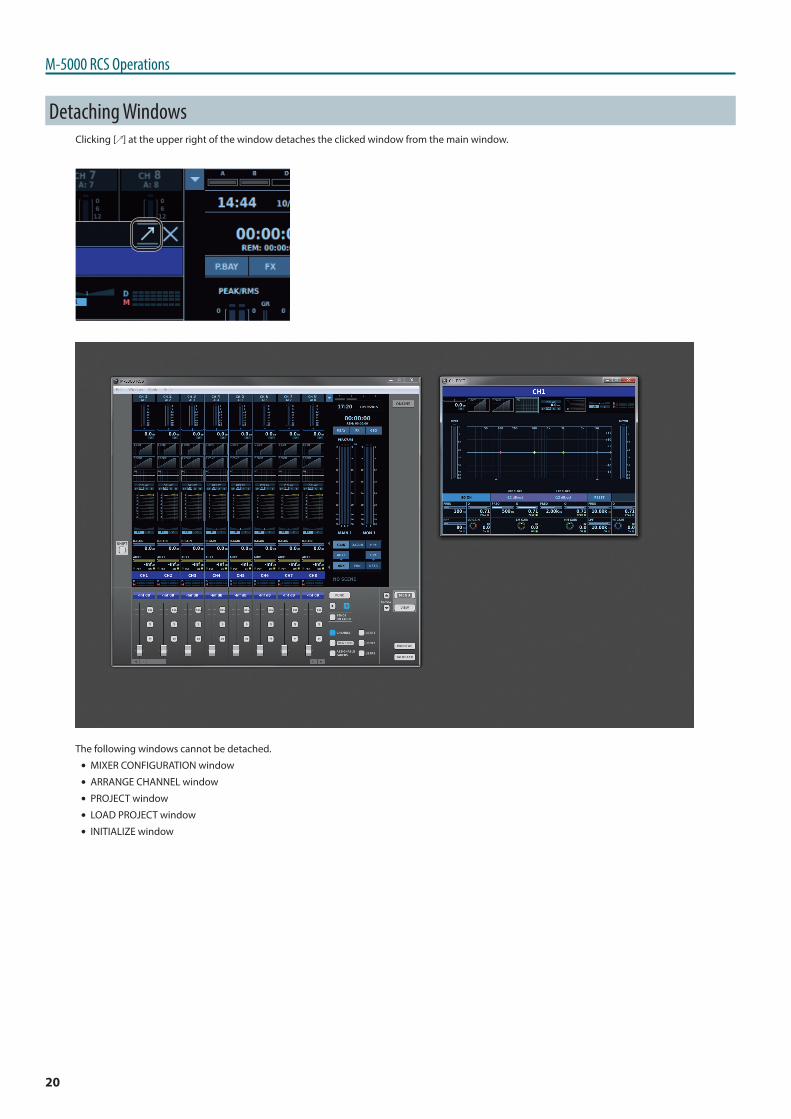
Detaching WindowsClicking [ ] at the upper right of the window detaches the clicked window from the main window.
The following windows cannot be detached.
5 MIXER CONFIGURATION window
5 ARRANGE CHANNEL window
5 PROJECT window
5 LOAD PROJECT window
5 INITIALIZE window
21
M-5000 RCS Operations
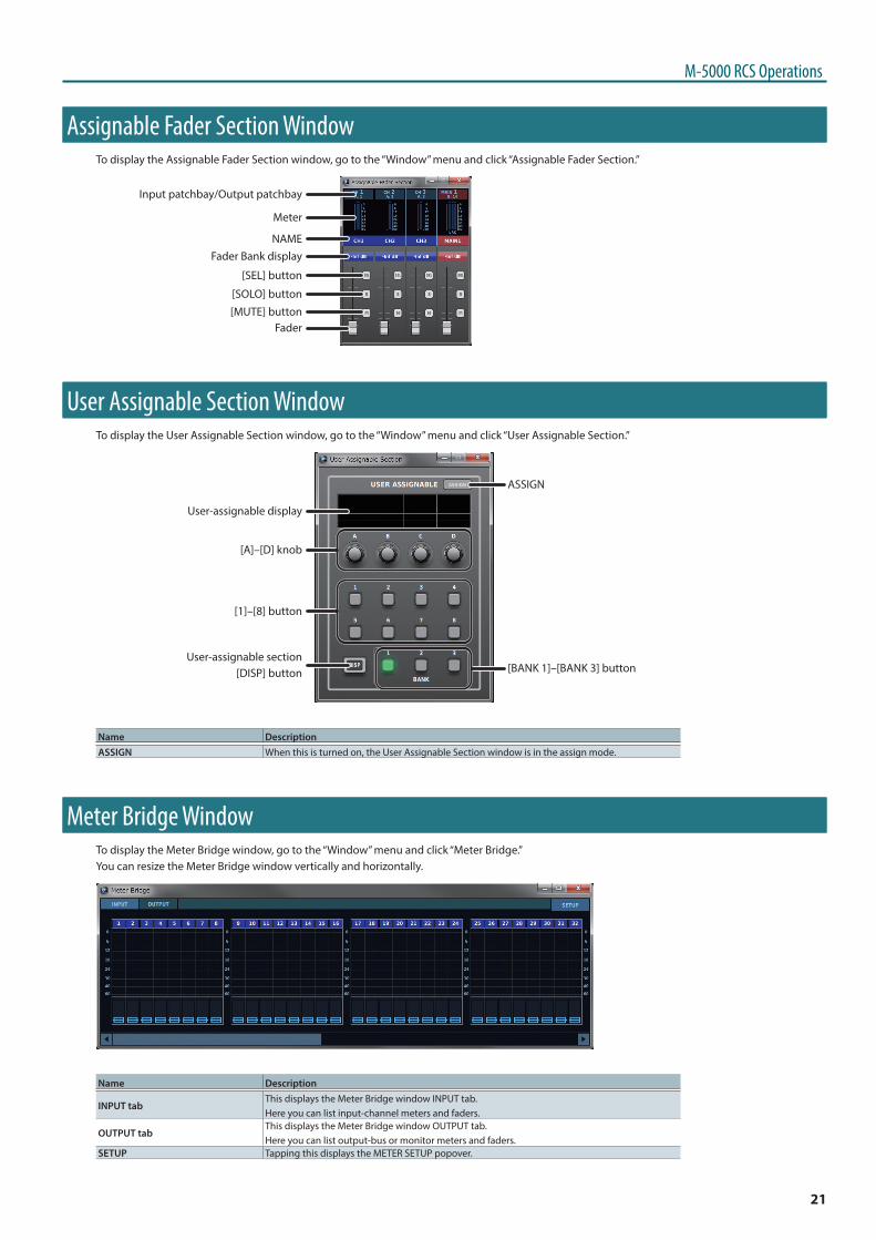
Assignable Fader Section WindowTo display the Assignable Fader Section window, go to the “Window” menu and click “Assignable Fader Section.”
Fader Bank displayNAME
Meter
Input patchbay/Output patchbay
Fader
[SEL] button
[SOLO] button
[MUTE] button
User Assignable Section WindowTo display the User Assignable Section window, go to the “Window” menu and click “User Assignable Section.”
User-assignable display
[A]–[D] knob
[1]–[8] button
User-assignable section[DISP] button [BANK 1]–[BANK 3] button
ASSIGN
Name DescriptionASSIGN When this is turned on, the User Assignable Section window is in the assign mode.
Meter Bridge WindowTo display the Meter Bridge window, go to the “Window” menu and click “Meter Bridge.”You can resize the Meter Bridge window vertically and horizontally.
Name Description
INPUT tabThis displays the Meter Bridge window INPUT tab.Here you can list input-channel meters and faders.
OUTPUT tabThis displays the Meter Bridge window OUTPUT tab.Here you can list output-bus or monitor meters and faders.
SETUP Tapping this displays the METER SETUP popover.
22
M-5000 RCS Operations
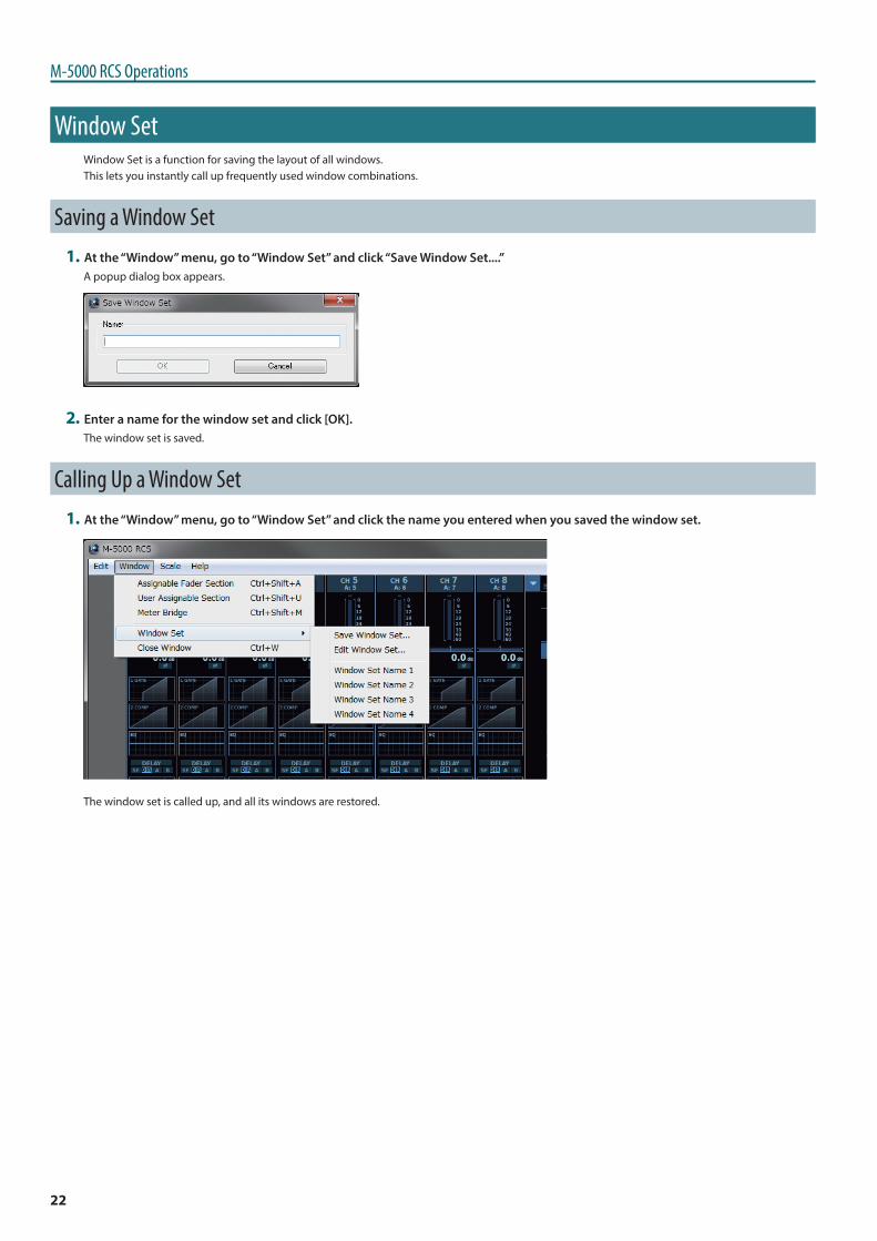
Window SetWindow Set is a function for saving the layout of all windows.This lets you instantly call up frequently used window combinations.
Saving a Window Set1 At the “Window” menu, go to “Window Set” and click “Save Window Set....”
A popup dialog box appears.
2 Enter a name for the window set and click [OK].The window set is saved.
Calling Up a Window Set1 At the “Window” menu, go to “Window Set” and click the name you entered when you saved the window set.
The window set is called up, and all its windows are restored.
23
M-5000 RCS Operations
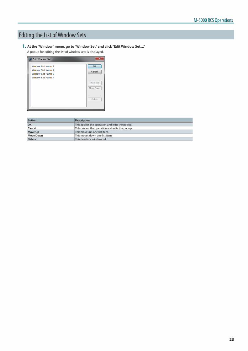
Editing the List of Window Sets1 At the “Window” menu, go to “Window Set” and click “Edit Window Set....”
A popup for editing the list of window sets is displayed.
Button DescriptionOK This applies the operation and exits the popup.Cancel This cancels the operation and exits the popup.Move Up This moves up one list item.Move Down This moves down one list item.Delete This deletes a window set.
24
M-5000 RCS Operations
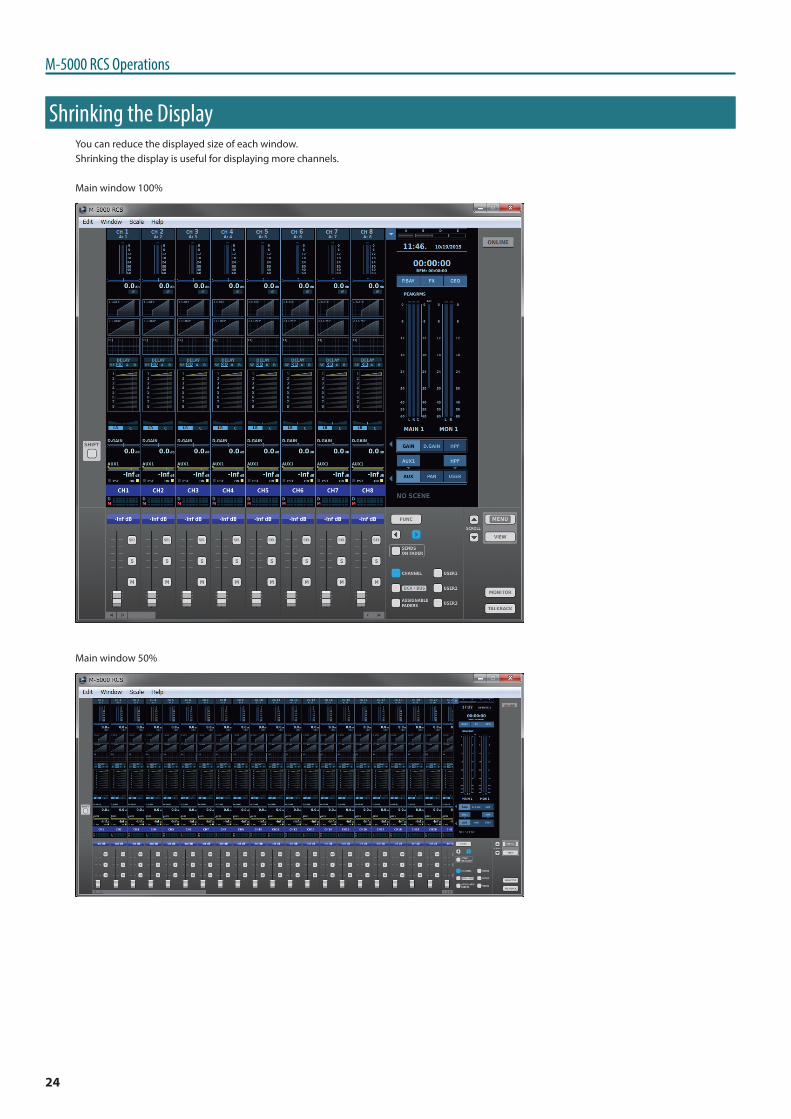
Shrinking the DisplayYou can reduce the displayed size of each window.Shrinking the display is useful for displaying more channels.
Main window 100%
Main window 50%
25
M-5000 RCS Operations
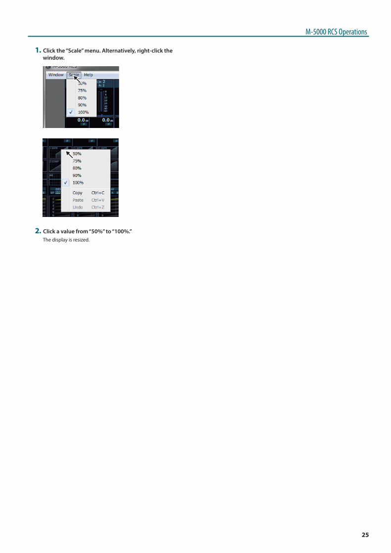
1 Click the “Scale” menu. Alternatively, right-click the window.
0
0
2 Click a value from “50%” to “100%.”The display is resized.
26
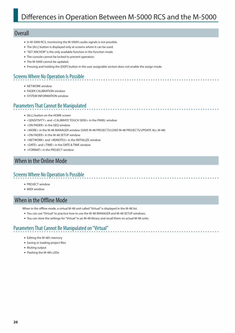
Differences in Operation Between M-5000 RCS and the M-5000
Overall 5 In M-5000 RCS, monitoring the M-5000’s audio signals is not possible.
5 The [ALL] button is displayed only at screens where it can be used.
5 “SET ANCHOR” is the only available function in the function mode.
5 The console cannot be locked to prevent operation.
5 The M-5000 cannot be updated.
5 Pressing and holding the [DISP] button in the user assignable section does not enable the assign mode.
Screens Where No Operation Is Possible
5 NETWORK window
5 FADER CALIBRATION window
5 SYSTEM INFORMATION window
Parameters That Cannot Be Manipulated
5 [ALL] button on the HOME screen
5 <SENSITIVITY> and <CALIBRATE TOUCH SENS> in the PANEL window
5 <ON FADER> in the GEQ window
5 <MORE> in the M-48 MANAGER window (SAVE M-48 PROJECTS/LOAD M-48 PROJECTS/UPDATE ALL M-48)
5 <ON FADER> in the M-48 SETUP window
5 <NETWORK> and <REMOTES> in the INITIALIZE window
5 <DATE> and <TIME> in the DATE & TIME window
5 <FORMAT> in the PROJECT window
When in the Online Mode
Screens Where No Operation Is Possible
5 PROJECT window
5 MIDI window
When in the Offline ModeWhen in the offline mode, a virtual M-48 unit called “Virtual” is displayed in the M-48 list.
5 You can use “Virtual” to practice how to use the M-48 MANAGER and M-48 SETUP windows.
5 You can store the settings for “Virtual” in an M-48 library and recall them on actual M-48 units.
Parameters That Cannot Be Manipulated on “Virtual”
5 Editing the M-48’s memory
5 Saving or loading project files
5 Muting output
5 Flashing the M-48’s LEDs

01


![[Rcs Iot] Rcs-e v1-2- Joyn](https://img.pdfslide.us/doc/110x75/577cd0231a28ab9e78917fbc/rcs-iot-rcs-e-v1-2-joyn.jpg)