Embed Size (px)
Citation preview
GE Energy
RCS* Actuators Versatile Automation Solutions
2 2 | Dresser
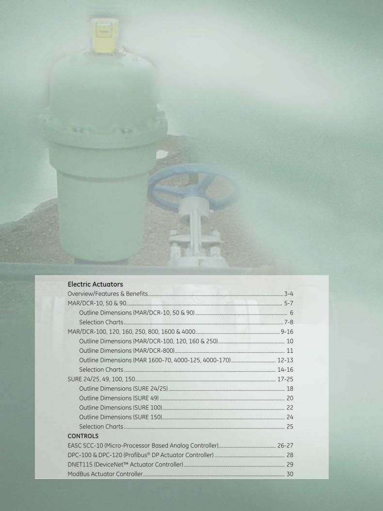
Electric Actuators Overview/Features & Benefits .......................................................................................................... 3-4
MAR/DCR-10, 50 & 90 .......................................................................................................................... 5-7
Outline Dimensions (MAR/DCR-10, 50 & 90) ........................................................................ 6
Selection Charts ............................................................................................................................. 7-8
MAR/DCR-100, 120, 160, 250, 800, 1600 & 4000.................................................................. 9-16
Outline Dimensions (MAR/DCR-100, 120, 160 & 250) .................................................... 10
Outline Dimensions (MAR/DCR-800) ...................................................................................... 11
Outline Dimensions (MAR 1600-70, 4000-125, 4000-170) ................................... 12-13
Selection Charts ....................................................................................................................... 14-16
SURE 24/25, 49, 100, 150 .............................................................................................................. 17-25
Outline Dimensions (SURE 24/25) ........................................................................................... 18
Outline Dimensions (SURE 49) .................................................................................................. 20
Outline Dimensions (SURE 100) ................................................................................................ 22
Outline Dimensions (SURE 150) ................................................................................................ 24
Selection Charts .............................................................................................................................. 25
CONTROLS EASC SCC-10 (Micro-Processor Based Analog Controller)............................................. 26-27
DPC-100 & DPC-120 (Profibus® DP Actuator Controller) ....................................................... 28
DNET115 (DeviceNet™ Actuator Controller) ............................................................................... 29
ModBus Actuator Controller ............................................................................................................... 30
RCS Actuators from GE Energy: Exceptional Automation Solutions RCS actuator products from GE Energy offer exceptional automation solutions for valve and equipment manufacturers and end users in the commercial, industrial, marine and power industries.
Applicable to a myriad of automation solutions, from simple on/off control to heavy modulating, RCS actuators have been used in a variety of challenging, dirty and hazardous environments. GE specializes in offering engineered actuator solutions for your unique or unusual applications.
Versatile, Advanced Technology Electric Rotary Actuators Our electric rotary line offers a broad range of highly versatile actuator products. Targeted to 1/4 turn and multi-turn valves and dampers, RCS electric rotary actuators are also well suited for use in the automation of other types of rotating equipment.
These rotary models span a torque range of 120 to 48,000 inch pounds with stroke speeds for 1/4 turn valves ranging from 0.5 seconds to 3 minutes and for multi-turn actuators from 7.5 to 30 rpm.
Cost-effective, Low-maintenance Spring Return Actuators Our spring return electric rotary actuators employ torsion power springs that provide a reliable mechanical actuation solution for emergency shutoff or shutdown situations. This approach offers a cost-effective, low-maintenance and superior alternative to pneumatic, hydraulic, electrohydraulic or battery backup systems.
The spring return electric rotary actuators have spring-ending torque to 1,800 inch pounds and are also available with speed options for simple on/off or modulating applications. Clockwise and counter-clockwise spring return options are available to drive any 1/4 turn device to a fail position upon loss of power.
An Extensive Array of the Latest Control Solutions GE offers an extensive line of electrical and electronic accessories for RCS actuators, including the latest solutions to industry demands for analog control plus communication bus capabilities, including the protocols supported are Profibus* DP, DeviceNet*, and Modbus*.
3

Features & Benefits Application Flexibility. RCS actuators from GE Energy offers a broad and diverse range of speeds and available voltages. Coupled with an extensive line of control and communication accessories, these actuators offer both standard and unique solutions to a host of automation requirements. Standard operation for MAR and DCR models is part turn, reversible with unidirectional and multi-turn options available.
Electric Motors. All RCS electric actuators are powered by an extended duty, high-torque, reversible motor. These motors are suitable for both on/off and modulating applications, with many models rated for extended duty. Each motor is Class “B” insulated and has an internal thermal overload protective device. This device protects the motor if a “stall” condition occurs thus preventing the motor from overheating which results in premature motor failure.
Precision Gearing. All gears used in RCS actuators are manufactured from high alloy steel. Each gear is precision machined, then heat-treated, giving the gears exceptional strength. Each gear assembly is designed and tested to withstand the stall torque generated by the motor.
Permanent Lubrication. Each gear and spring assembly is permanently lubricated with a high quality lubricant selected to meet a wide range of operational and environmental conditions. Periodic lubrication is not required.
Versatile Installation. All RCS actuators can be installed and operated in any position. This allows flexibility for installation in confined locations or in retrofit applications.
Manual Override. MAR/DCR10, 50 and 90 models feature a declutchable manual override. The actuator gearing is disengaged from the motor thus the actuator cannot be operated electrically while in manual operation. MAR100 through 4000 feature a manual override with an automatic electrical safety lockout switch. When the handwheel is engaged, the electrical switch isolates the motor from the supply voltage to prevent electrical operation.
Environmental. With electroless nickel plated output shafts and stainless steel external bolting, RCS actuators will stand up to a broad range of environmental conditions. Optional marine epoxy paint systems or electroless nickel plated enclosures are also available to meet most onshore or offshore conditions. Standard Coating System. Electrostatically applied powder coating
Optional Coating System. Ameron 2 part, water based epoxy, Sherwin Williams KEM Aqua °280 Water Reducible Enamel, or Electroless Nickel Plating
Position Indication. Mechanical position indicators are standard on every model. These devices provide an external position reference for the actuator or driven equipment.
Simple and Easy Wiring. Every actuator has a clearly marked and accessible terminal strip to provide for quick termination of field wiring.
Accessories. ■ Integral potentiometer ■ Auxiliary limit switches ■ Interposing relays ■ Motor brakes ■ D.C. analog position transmitter with integral
power supply ■ D.C. analog position (loop powered) ■ D.C. analog position controller ■ Digi-Tork bi-directional torque control ■ Digi-Speed variable speed control ■ Communication bus interface:
- Profibus DP - DeviceNet™
- Modbus
4
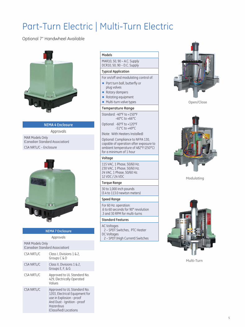
Part-Turn Electric | Multi-Turn Electric Optional 7” Handwheel Available
Open/Close
Models
MAR10, 50, 90 – A.C. Supply DCR10, 50, 90 – D.C. Supply
Typical Application
For on/off and modulating control of:
■ Part turn ball, butterfly or plug valves
■ Rotary dampers
■ Rotating equipment
■ Multi-turn valve types
Temperature Range
Standard: -40°F to +150°F -40°C to +66°C
Optional: -60°F to +120°F -51°C to +49°C
(Note: With Heaters Installed)
Optional: Compliance to NFPA 130, capable of operation after exposure to ambient temperature of 482°F (250°C) for a minimum of 1 hour
Voltage
115 VAC, 1 Phase, 50/60 Hz. 230 VAC, 1 Phase, 50/60 Hz. 24 VAC, 1 Phase, 50/60 Hz. 12 VDC / 24 VDC
Torque Range
30 to 1,000 inch pounds (3.4 to 113.0 newton meters)
Speed Range
For 60 Hz. operation: .6 to 60 seconds for 90° revolution .3 and 30 RPM for multi-turns
Standard Features
AC Voltages 2 – SPDT Switches, PTC Heater
DC Voltages 2 – SPDT (High Current) Switches
NEMA 4 Enclosure
Approvals
MAR Models Only (Canadian Standard Association)
CSA NRTL/C – Enclosure
Modulating
NEMA 7 Enclosure
Approvals
MAR Models Only (Canadian Standard Association)
CSA NRTL/C Class I, Divisions 1 & 2,
Multi-Turn Groups C & D
CSA NRTL/C Class II, Divisions 1 & 2, Groups E, F, & G
CSA NRTL/C Approved to UL Standard No. 429, Electrically Operated Values
CSA NRTL/C Approved to UL Standard No. 1203, Electrical Equipment for use in Explosion - proof And Dust - Ignition - proof Hazardous (Classified) Locations
5
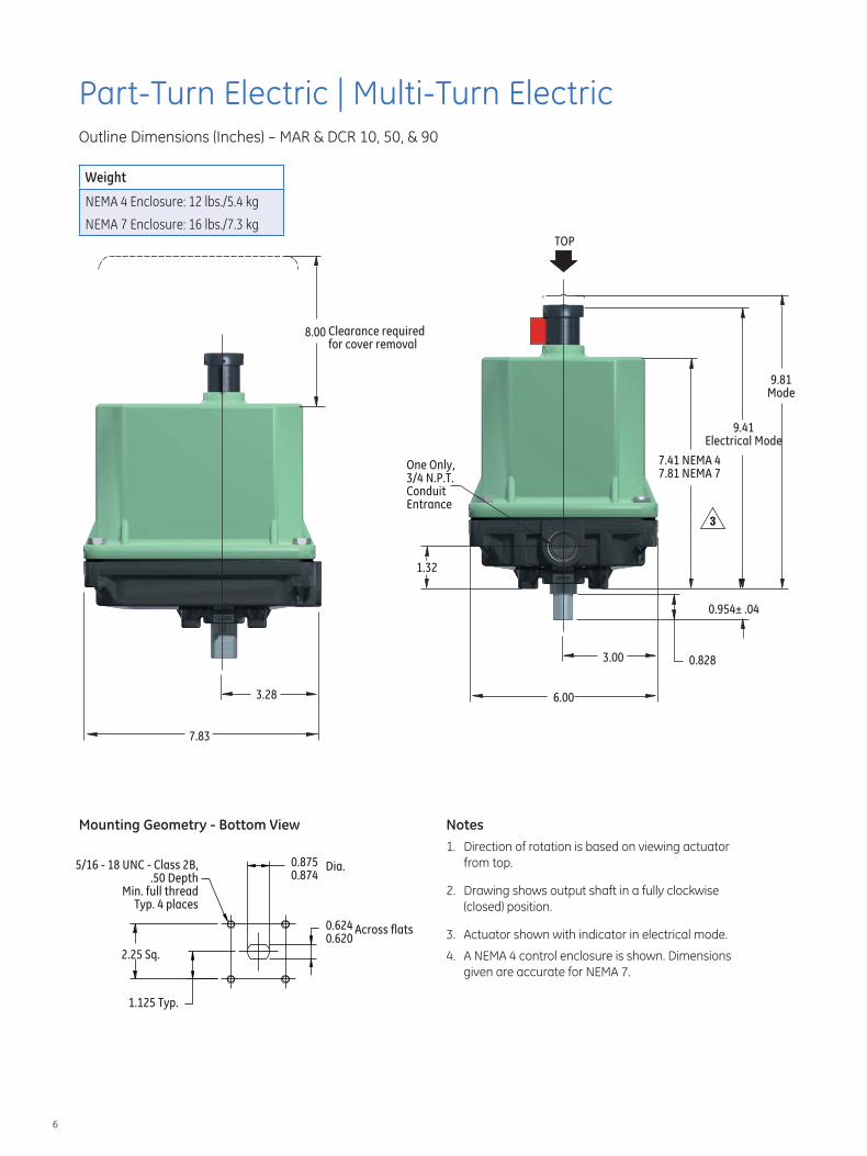
Part-Turn Electric | Multi-Turn Electric Outline Dimensions (Inches) – MAR & DCR 10, 50, & 90
Weight
NEMA 4 Enclosure: 12 lbs./5.4 kg
NEMA 7 Enclosure: 16 lbs./7.3 kg TOP
3
One Only, 3/4 N.P.T. Conduit Entrance
1.32
3.00 0.828
0.954± .04
9.41 Electrical Mode
6.00
9.81 Mode
7.41 NEMA 4 7.81 NEMA 7
8.00 Clearance required for cover removal
7.83
3.28
Mounting Geometry - Bottom View Notes 1. Direction of rotation is based on viewing actuator from top. Dia.
2. Drawing shows output shaft in a fully clockwise (closed) position.
0.624 Across flats 3. Actuator shown with indicator in electrical mode.0.620
4. A NEMA 4 control enclosure is shown. Dimensions given are accurate for NEMA 7.
0.875 0.874
1.125 Typ.
5/16 - 18 UNC - Class 2B, .50 Depth
Min. full thread Typ. 4 places
2.25 Sq.
6
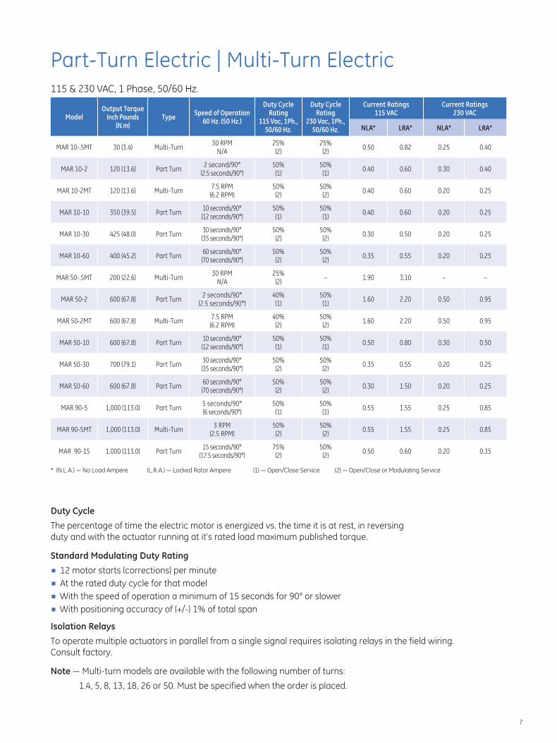
Part-Turn Electric | Multi-Turn Electric 115 & 230 VAC, 1 Phase, 50/60 Hz.
Model Output Torque
Inch Pounds (N.m)
Type Speed of Operation
60 Hz. (50 Hz.)
Duty Cycle Rating
115 Vac, 1Ph., 50/60 Hz.
Duty Cycle Rating
230 Vac, 1Ph., 50/60 Hz.
Current Ratings 115 VAC
Current Ratings 230 VAC
NLA* LRA* NLA* LRA*
MAR 10-.5MT 30 (3.4) Multi-Turn 30 RPM
N/A 25% (2)
25% (2)
0.50 0.82 0.25 0.40
MAR 10-2 120 (13.6) Part Turn 2 second/90°
(2.5 seconds/90°) 50% (1)
50% (1)
0.40 0.60 0.30 0.40
MAR 10-2MT 120 (13.6) Multi-Turn 7.5 RPM (6.2 RPM)
50% (2)
50% (2)
0.40 0.60 0.20 0.25
MAR 10-10 350 (39.5) Part Turn 10 seconds/90° (12 seconds/90°)
50% (1)
50% (1)
0.40 0.60 0.20 0.25
MAR 10-30 425 (48.0) Part Turn 30 seconds/90° (35 seconds/90°)
50% (2)
50% (2)
0.30 0.50 0.20 0.25
MAR 10-60 400 (45.2) Part Turn 60 seconds/90° (70 seconds/90°)
50% (2)
50% (2)
0.35 0.55 0.20 0.25
MAR 50-.5MT 200 (22.6) Multi-Turn 30 RPM
N/A 25% (2)
– 1.90 3.10 – –
MAR 50-2 600 (67.8) Part Turn 2 seconds/90°
(2.5 seconds/90°) 40% (1)
50% (1)
1.60 2.20 0.50 0.95
MAR 50-2MT 600 (67.8) Multi-Turn 7.5 RPM (6.2 RPM)
40% (2)
50% (2)
1.60 2.20 0.50 0.95
MAR 50-10 600 (67.8) Part Turn 10 seconds/90° (12 seconds/90°)
50% (1)
50% (1)
0.50 0.80 0.30 0.50
MAR 50-30 700 (79.1) Part Turn 30 seconds/90° (35 seconds/90°)
50% (2)
50% (2)
0.35 0.55 0.20 0.25
MAR 50-60 600 (67.8) Part Turn 60 seconds/90° (70 seconds/90°)
50% (2)
50% (2)
0.30 1.50 0.20 0.25
MAR 90-5 1,000 (113.0) Part Turn 5 seconds/90° (6 seconds/90°)
50% (1)
50% (1)
0.55 1.55 0.25 0.85
MAR 90-5MT 1,000 (113.0) Multi-Turn 3 RPM
(2.5 RPM) 50% (2)
50% (2)
0.55 1.55 0.25 0.85
15 seconds/90° 75% 50%MAR 90-15 1,000 (113.0) Part Turn 0.50 0.60 0.20 0.35
(17.5 seconds/90°) (2) (2)
* (N.L.A.) — No Load Ampere (L.R.A.) — Locked Rotor Ampere (1) — Open/Close Service (2) — Open/Close or Modulating Service
Duty Cycle
The percentage of time the electric motor is energized vs. the time it is at rest, in reversing duty and with the actuator running at it’s rated load maximum published torque.
Standard Modulating Duty Rating ■ 12 motor starts (corrections) per minute ■ At the rated duty cycle for that model ■ With the speed of operation a minimum of 15 seconds for 90° or slower ■ With positioning accuracy of (+/-) 1% of total span
Isolation Relays
To operate multiple actuators in parallel from a single signal requires isolating relays in the field wiring. Consult factory.
Note — Multi-turn models are available with the following number of turns:
1.4, 5, 8, 13, 18, 26 or 50. Must be specified when the order is placed.
7
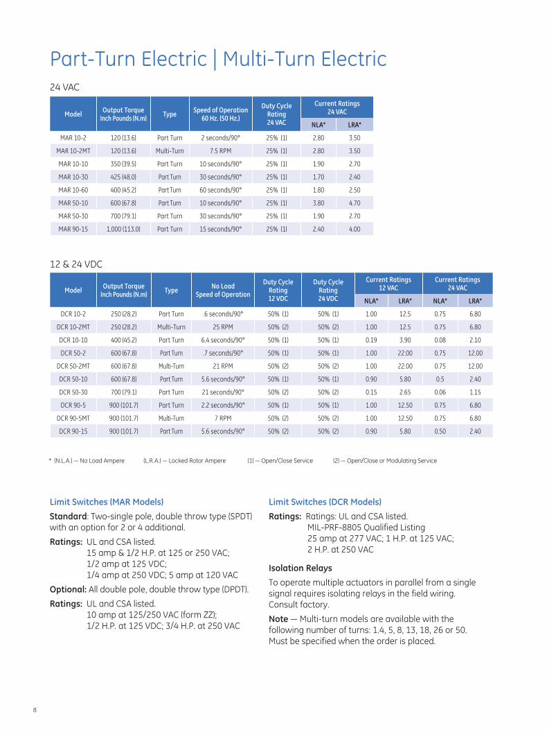
Part-Turn Electric | Multi-Turn Electric 24 VAC
Model Output Torque
Inch Pounds (N.m) Type
Speed of Operation 60 Hz. (50 Hz.)
Duty Cycle Rating 24 VAC
Current Ratings 24 VAC
NLA* LRA*
MAR 10-2 120 (13.6) Part Turn 2 seconds/90° 25% (1) 2.80 3.50
MAR 10-2MT 120 (13.6) Multi-Turn 7.5 RPM 25% (1) 2.80 3.50
MAR 10-10 350 (39.5) Part Turn 10 seconds/90° 25% (1) 1.90 2.70
MAR 10-30 425 (48.0) Part Turn 30 seconds/90° 25% (1) 1.70 2.40
MAR 10-60 400 (45.2) Part Turn 60 seconds/90° 25% (1) 1.80 2.50
MAR 50-10 600 (67.8) Part Turn 10 seconds/90° 25% (1) 3.80 4.70
MAR 50-30 700 (79.1) Part Turn 30 seconds/90° 25% (1) 1.90 2.70
MAR 90-15 1,000 (113.0) Part Turn 15 seconds/90° 25% (1) 2.40 4.00
12 & 24 VDC
Model Output Torque
Inch Pounds (N.m) Type
No Load Speed of Operation
Duty Cycle Rating 12 VDC
Duty Cycle Rating 24 VDC
Current Ratings 12 VAC
Current Ratings 24 VAC
NLA* LRA* NLA* LRA*
DCR 10-2 250 (28.2) Part Turn .6 seconds/90° 50% (1) 50% (1) 1.00 12.5 0.75 6.80
DCR 10-2MT 250 (28.2) Multi-Turn 25 RPM 50% (2) 50% (2) 1.00 12.5 0.75 6.80
DCR 10-10 400 (45.2) Part Turn 6.4 seconds/90° 50% (1) 50% (1) 0.19 3.90 0.08 2.10
DCR 50-2 600 (67.8) Part Turn .7 seconds/90° 50% (1) 50% (1) 1.00 22.00 0.75 12.00
DCR 50-2MT 600 (67.8) Multi-Turn 21 RPM 50% (2) 50% (2) 1.00 22.00 0.75 12.00
DCR 50-10 600 (67.8) Part Turn 5.6 seconds/90° 50% (1) 50% (1) 0.90 5.80 0.5 2.40
DCR 50-30 700 (79.1) Part Turn 21 seconds/90° 50% (2) 50% (2) 0.15 2.65 0.06 1.15
DCR 90-5 900 (101.7) Part Turn 2.2 seconds/90° 50% (1) 50% (1) 1.00 12.50 0.75 6.80
DCR 90-5MT 900 (101.7) Multi-Turn 7 RPM 50% (2) 50% (2) 1.00 12.50 0.75 6.80
DCR 90-15 900 (101.7) Part Turn 5.6 seconds/90° 50% (2) 50% (2) 0.90 5.80 0.50 2.40
* (N.L.A.) — No Load Ampere (L.R.A.) — Locked Rotor Ampere (1) — Open/Close Service (2) — Open/Close or Modulating Service
Limit Switches (MAR Models) Limit Switches (DCR Models)
Standard: Two-single pole, double throw type (SPDT) Ratings: Ratings: UL and CSA listed. with an option for 2 or 4 additional. MIL-PRF-8805 Qualified Listing
25 amp at 277 VAC; 1 H.P. at 125 VAC;Ratings: UL and CSA listed. 2 H.P. at 250 VAC15 amp & 1/2 H.P. at 125 or 250 VAC;
1/2 amp at 125 VDC; Isolation Relays1/4 amp at 250 VDC; 5 amp at 120 VAC
To operate multiple actuators in parallel from a singleOptional: All double pole, double throw type (DPDT). signal requires isolating relays in the field wiring. Ratings: UL and CSA listed. Consult factory.
10 amp at 125/250 VAC (form ZZ); Note — Multi-turn models are available with the 1/2 H.P. at 125 VDC; 3/4 H.P. at 250 VAC following number of turns: 1.4, 5, 8, 13, 18, 26 or 50.
Must be specified when the order is placed.
8
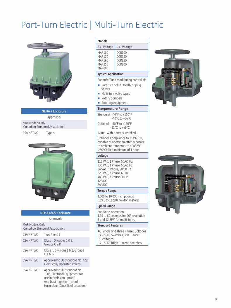
Part-Turn Electric | Multi-Turn Electric
NEMA 4 Enclosure
Approvals
MAR Models Only (Canadian Standard Association)
CSA NRTL/C Type 4
NEMA 4/6/7 Enclosure
Approvals
MAR Models Only (Canadian Standard Association)
CSA NRTL/C Type 4 and 6
CSA NRTL/C Class I, Divisions 1 & 2, Groups C & D
Models
A.C. Voltage D.C. Voltage
MAR100 MAR120 MAR160 MAR250 MAR800
DCR100 DCR160 DCR250 DCR800
Typical Application
For on/off and modulating control of:
■ Part turn ball, butterfly or plug valves
■ Multi-turn valve types
■ Rotary dampers
■ Rotating equipment
Temperature Range
Standard: -40°F to +150°F -40°C to +66°C
Optional: -60°F to +120°F -51°C to +49°C
(Note: With Heaters Installed)
Optional: Compliance to NFPA 130, capable of operation after exposure to ambient temperature of 482°F (250°C) for a minimum of 1 hour
Voltage
115 VAC, 1 Phase, 50/60 Hz. 230 VAC, 1 Phase, 50/60 Hz. 24 VAC, 1 Phase, 50/60 Hz. 220 VAC, 3 Phase, 60 Hz. 440 VAC, 3 Phase 60 Hz. 12 VDC 24 VDC
Torque Range
1,500 to 10,000 inch pounds (169.5 to 1129.8 newton meters)
Speed Range
For 60 Hz. operation: 1 .25 to 60 seconds for 90° revolution 5 and 12 RPM for multi-turns
Standard Features
AC (Single and Three Phase ) Voltages 4 – SPDT Switches, PTC Heater
DC Voltages 4 – SPDT (High Current) Switches
CSA NRTL/C Class II, Divisions 1 & 2, Groups E, F & G
CSA NRTL/C Approved to UL Standard No. 429, Electrically Operated Valves
CSA NRTL/C Approved to UL Standard No. 1203, Electrical Equipment for use in Explosion - proof And Dust - Ignition - proof Hazardous (Classified) Locations
9
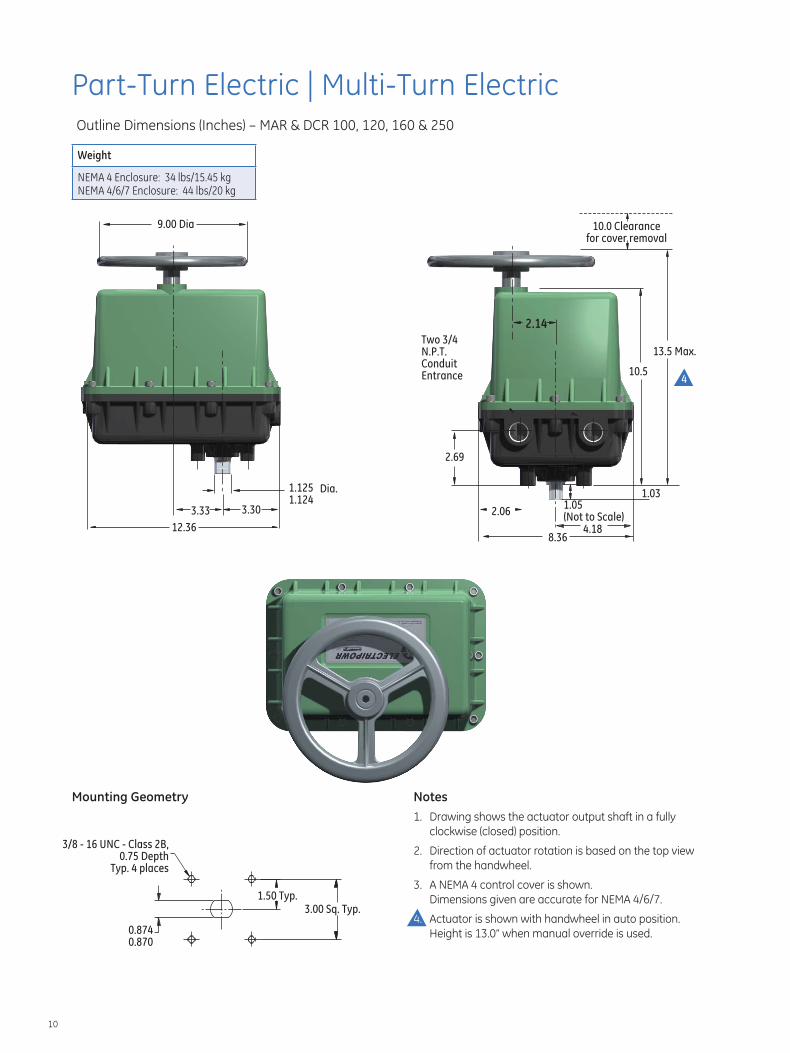
Part-Turn Electric | Multi-Turn Electric Outline Dimensions (Inches) – MAR & DCR 100, 120, 160 & 250
Weight
NEMA 4 Enclosure: 34 lbs/15.45 kg NEMA 4/6/7 Enclosure: 44 lbs/20 kg
12.36
3.303.33
9.00 Dia 10.0 Clearance for cover removal
Two 3/4 13.5 Max.
Conduit N.P.T.
10.5Entrance
1.125 Dia. 1.124
8.36
2.14
2.69
2.06
1.03 1.05 (Not to Scale)
4.18
Mounting Geometry Notes 1. Drawing shows the actuator output shaft in a fully
clockwise (closed) position. 3/8 - 16 UNC - Class 2B, 2. Direction of actuator rotation is based on the top view 0.75 Depth
Typ. 4 places from the handwheel.
3. A NEMA 4 control cover is shown. 1.50 Typ. Dimensions given are accurate for NEMA 4/6/7.
3.00 Sq. Typ. 4. Actuator is shown with handwheel in auto position.
0.874 Height is 13.0” when manual override is used. 0.870
10
4
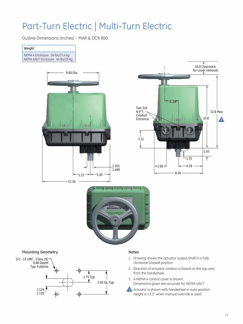
Part-Turn Electric | Multi-Turn Electric Outline Dimensions (Inches) – MAR & DCR 800
Weight
NEMA 4 Enclosure: 34 lbs/15.4 kg NEMA 4/6/7 Enclosure: 44 lbs/20 kg
10.0 Clearance for cover removal
9.00 Dia.
13.8 Max
1.501 2.06 4.18 1.499
8.363.33 3.30
2.14
1.35
1.50
10.8
3.31
Two 3/4 N.P.T. Conduit Entrance
1.50
12.36
4
Mounting Geometry Notes 1. Drawing shows the actuator output shaft in a fully 1/2 - 13 UNC - Class 2B,
0.88 Depth clockwise (closed) position. Typ. 4 places
2. Direction of actuator rotation is based on the top view from the handwheel.
1.75 Typ. 3. A NEMA 4 control cover is shown.
3.50 Sq. Typ. Dimensions given are accurate for NEMA 4/6/7.
1.124 4. Actuator is shown with handwheel in auto position. 1.120 Height is 13.3” when manual override is used.
11
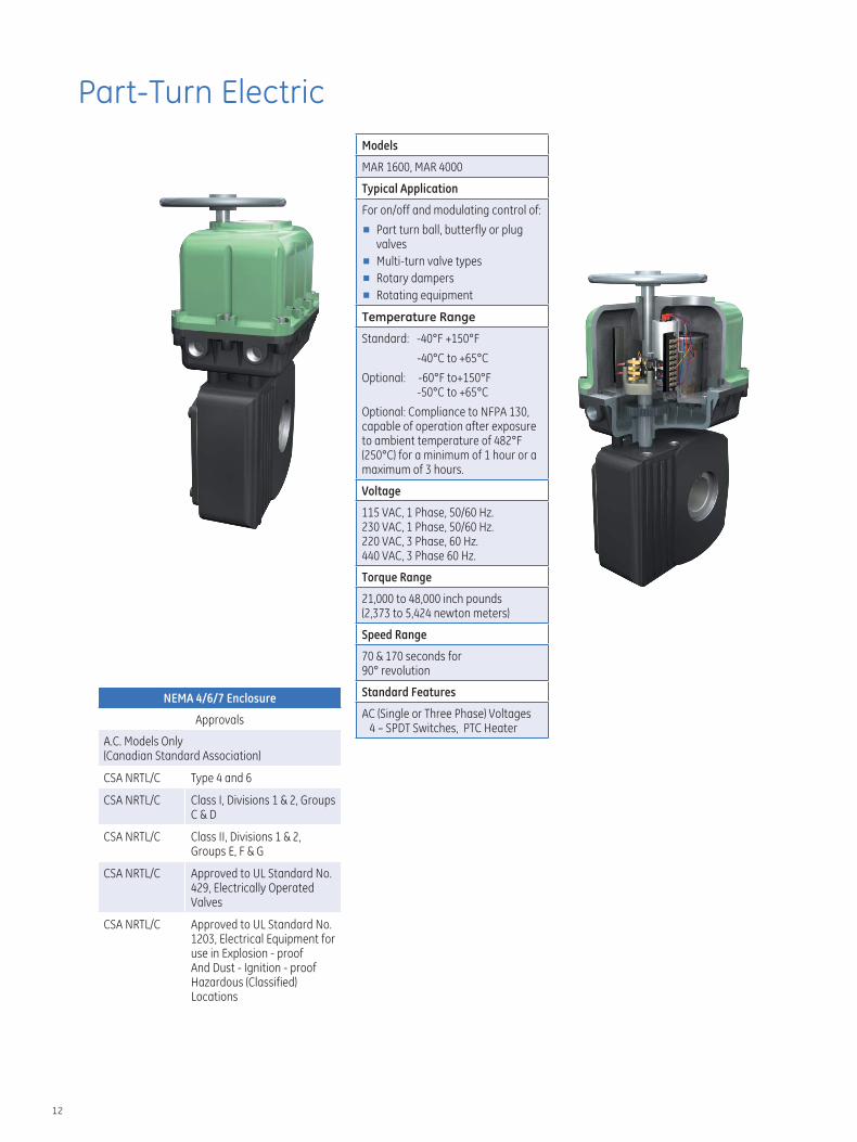
Part-Turn Electric Models
MAR 1600, MAR 4000
Typical Application
For on/off and modulating control of:
■ Part turn ball, butterfly or plug valves
■ Multi-turn valve types
■ Rotary dampers
■ Rotating equipment
Temperature Range
Standard: -40°F +150°F
-40°C to +65°C
Optional: -60°F to+150°F -50°C to +65°C
Optional: Compliance to NFPA 130, capable of operation after exposure to ambient temperature of 482°F (250°C) for a minimum of 1 hour or a maximum of 3 hours.
Voltage
115 VAC, 1 Phase, 50/60 Hz. 230 VAC, 1 Phase, 50/60 Hz. 220 VAC, 3 Phase, 60 Hz. 440 VAC, 3 Phase 60 Hz.
Torque Range
21,000 to 48,000 inch pounds (2,373 to 5,424 newton meters)
Speed Range
70 & 170 seconds for 90° revolution
Standard Features
AC (Single or Three Phase) Voltages 4 – SPDT Switches, PTC Heater
NEMA 4/6/7 Enclosure
Approvals
A.C. Models Only (Canadian Standard Association)
CSA NRTL/C Type 4 and 6
CSA NRTL/C Class I, Divisions 1 & 2, Groups C & D
CSA NRTL/C Class II, Divisions 1 & 2, Groups E, F & G
CSA NRTL/C Approved to UL Standard No. 429, Electrically Operated Valves
CSA NRTL/C Approved to UL Standard No. 1203, Electrical Equipment for use in Explosion - proof And Dust - Ignition - proof Hazardous (Classified) Locations
12
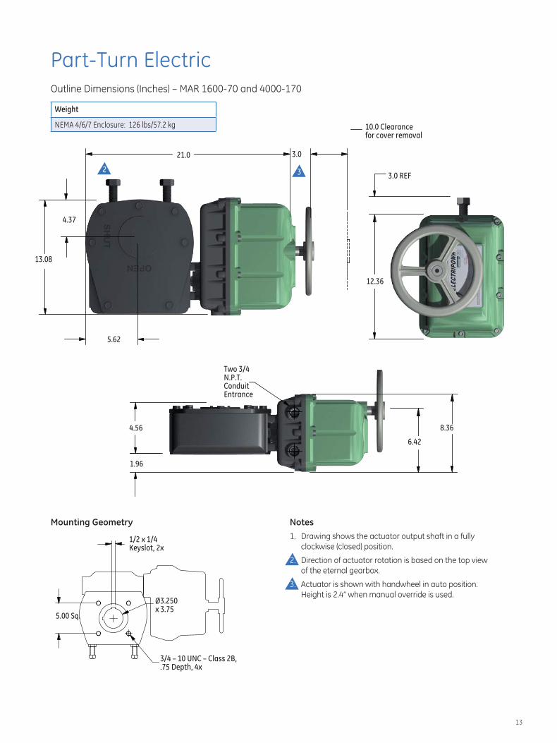
Part-Turn Electric Outline Dimensions (Inches) – MAR 1600-70 and 4000-170
Weight
NEMA 4/6/7 Enclosure: 126 lbs/57.2 kg 10.0 Clearance for cover removal
3.0 REF
13.08
5.62
4.37
3.021.0
12.36
8.36
1.96
4.56
6.42
Two 3/4 N.P.T. Conduit Entrance
32
Mounting Geometry Notes 1. Drawing shows the actuator output shaft in a fully
clockwise (closed) position.
Direction of actuator rotation is based on the top view of the eternal gearbox.
2.
3. Actuator is shown with handwheel in auto position. Height is 2.4” when manual override is used.
1/2 x 1/4 Keyslot, 2x
5.00 Sq.
Ø3.250 x 3.75
3/4 – 10 UNC – Class 2B, .75 Depth, 4x
13
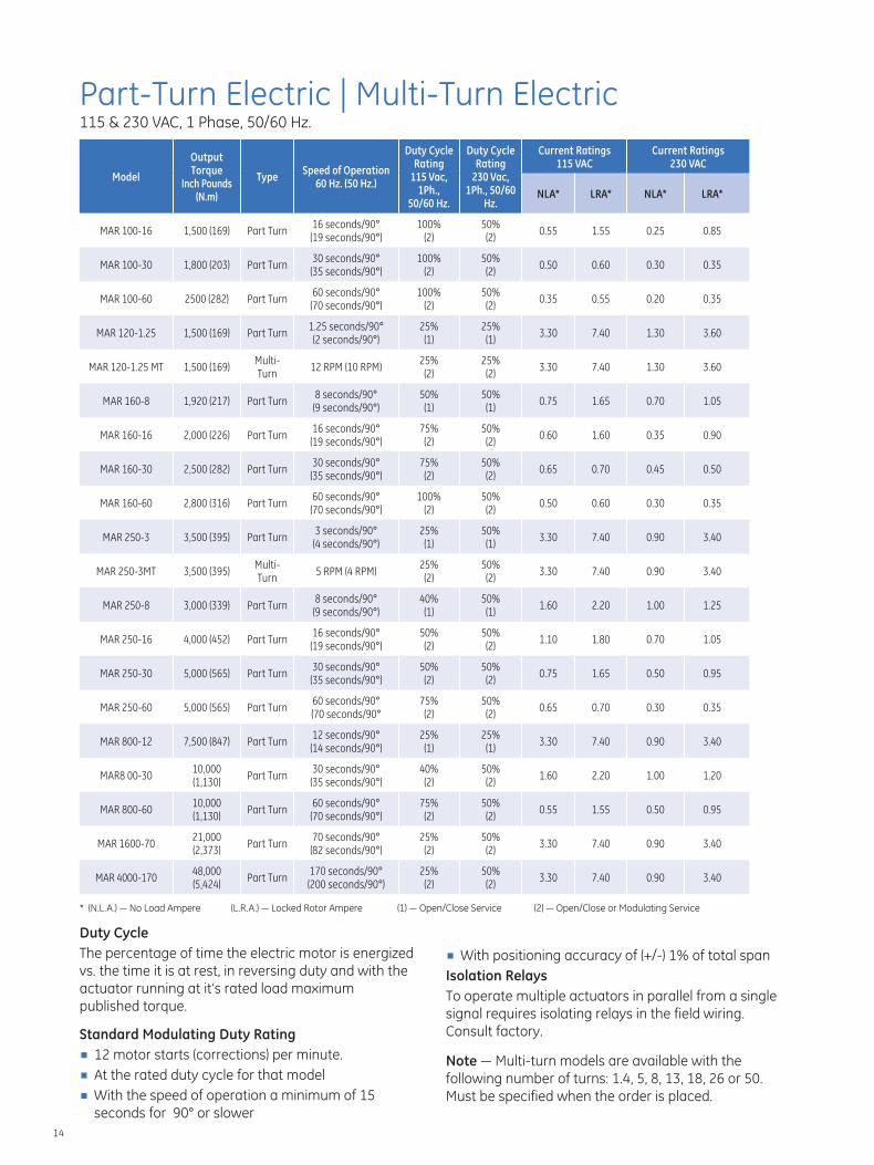
Part-Turn Electric | Multi-Turn Electric 115 & 230 VAC, 1 Phase, 50/60 Hz.
Model
Output Torque
Inch Pounds (N.m)
Type Speed of Operation
60 Hz. (50 Hz.)
Duty Cycle Rating
115 Vac, 1Ph.,
50/60 Hz.
Duty Cycle Rating
230 Vac, 1Ph., 50/60
Hz.
Current Ratings 115 VAC
Current Ratings 230 VAC
NLA* LRA* NLA* LRA*
MAR 100-16 1,500 (169) Part Turn 16 seconds/90° (19 seconds/90°)
100% (2)
50% (2)
0.55 1.55 0.25 0.85
MAR 100-30 1,800 (203) Part Turn 30 seconds/90° (35 seconds/90°)
100% (2)
50% (2)
0.50 0.60 0.30 0.35
MAR 100-60 2500 (282) Part Turn 60 seconds/90° (70 seconds/90°)
100% (2)
50% (2)
0.35 0.55 0.20 0.35
MAR 120-1.25 1,500 (169) Part Turn 1.25 seconds/90° (2 seconds/90°)
25% (1)
25% (1)
3.30 7.40 1.30 3.60
MAR 120-1.25 MT 1,500 (169) Multi-Turn
12 RPM (10 RPM) 25% (2)
25% (2)
3.30 7.40 1.30 3.60
MAR 160-8 1,920 (217) Part Turn 8 seconds/90° (9 seconds/90°)
50% (1)
50% (1)
0.75 1.65 0.70 1.05
MAR 160-16 2,000 (226) Part Turn 16 seconds/90° (19 seconds/90°)
75% (2)
50% (2)
0.60 1.60 0.35 0.90
MAR 160-30 2,500 (282) Part Turn 30 seconds/90° (35 seconds/90°)
75% (2)
50% (2)
0.65 0.70 0.45 0.50
MAR 160-60 2,800 (316) Part Turn 60 seconds/90° (70 seconds/90°)
100% (2)
50% (2)
0.50 0.60 0.30 0.35
MAR 250-3 3,500 (395) Part Turn 3 seconds/90° (4 seconds/90°)
25% (1)
50% (1)
3.30 7.40 0.90 3.40
MAR 250-3MT 3,500 (395) Multi-Turn
5 RPM (4 RPM) 25% (2)
50% (2)
3.30 7.40 0.90 3.40
MAR 250-8 3,000 (339) Part Turn 8 seconds/90° (9 seconds/90°)
40% (1)
50% (1)
1.60 2.20 1.00 1.25
MAR 250-16 4,000 (452) Part Turn 16 seconds/90° (19 seconds/90°)
50% (2)
50% (2)
1.10 1.80 0.70 1.05
MAR 250-30 5,000 (565) Part Turn 30 seconds/90° (35 seconds/90°)
50% (2)
50% (2)
0.75 1.65 0.50 0.95
MAR 250-60 5,000 (565) Part Turn 60 seconds/90° (70 seconds/90°
75% (2)
50% (2)
0.65 0.70 0.30 0.35
MAR 800-12 7,500 (847) Part Turn 12 seconds/90° (14 seconds/90°)
25% (1)
25% (1)
3.30 7.40 0.90 3.40
MAR8 00-30 10,000 (1,130)
Part Turn 30 seconds/90° (35 seconds/90°)
40% (2)
50% (2)
1.60 2.20 1.00 1.20
MAR 800-60 10,000 (1,130)
Part Turn 60 seconds/90° (70 seconds/90°)
75% (2)
50% (2)
0.55 1.55 0.50 0.95
MAR 1600-70 21,000 (2,373)
Part Turn 70 seconds/90° (82 seconds/90°)
25% (2)
50% (2)
3.30 7.40 0.90 3.40
MAR 4000-170 48,000 (5,424)
Part Turn 170 seconds/90° (200 seconds/90°)
25% (2)
50% (2)
3.30 7.40 0.90 3.40
* (N.L.A.) — No Load Ampere (L.R.A.) — Locked Rotor Ampere (1) — Open/Close Service (2) — Open/Close or Modulating Service
Duty Cycle The percentage of time the electric motor is energized ■ With positioning accuracy of (+/-) 1% of total spanvs. the time it is at rest, in reversing duty and with the Isolation Relays actuator running at it’s rated load maximum To operate multiple actuators in parallel from a singlepublished torque. signal requires isolating relays in the field wiring. Standard Modulating Duty Rating Consult factory.
■ 12 motor starts (corrections) per minute. Note — Multi-turn models are available with the ■ At the rated duty cycle for that model following number of turns: 1.4, 5, 8, 13, 18, 26 or 50. ■ With the speed of operation a minimum of 15 Must be specified when the order is placed.
seconds for 90° or slower 14
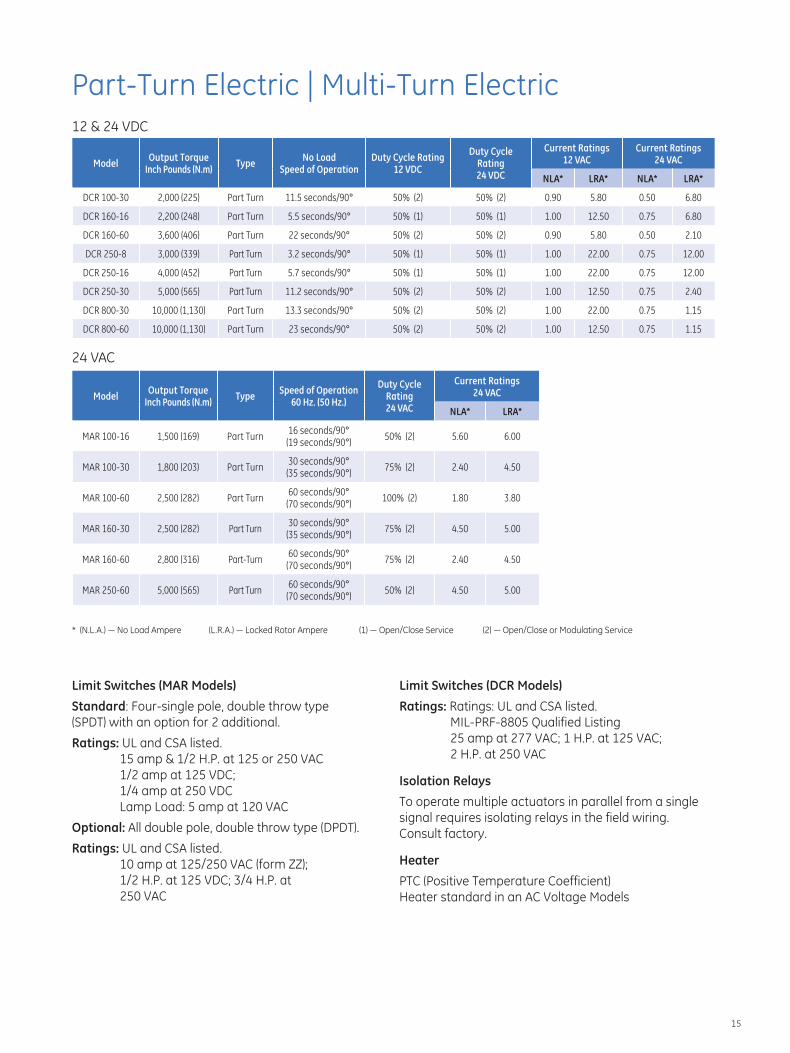
Part-Turn Electric | Multi-Turn Electric 12 & 24 VDC
Model Output Torque
Inch Pounds (N.m) Type
No Load Speed of Operation
Duty Cycle Rating 12 VDC
Duty Cycle Rating 24 VDC
Current Ratings 12 VAC
Current Ratings 24 VAC
NLA* LRA* NLA* LRA*
DCR 100-30 2,000 (225) Part Turn 11.5 seconds/90° 50% (2) 50% (2) 0.90 5.80 0.50 6.80
DCR 160-16 2,200 (248) Part Turn 5.5 seconds/90° 50% (1) 50% (1) 1.00 12.50 0.75 6.80
DCR 160-60 3,600 (406) Part Turn 22 seconds/90° 50% (2) 50% (2) 0.90 5.80 0.50 2.10
DCR 250-8 3,000 (339) Part Turn 3.2 seconds/90° 50% (1) 50% (1) 1.00 22.00 0.75 12.00
DCR 250-16 4,000 (452) Part Turn 5.7 seconds/90° 50% (1) 50% (1) 1.00 22.00 0.75 12.00
DCR 250-30 5,000 (565) Part Turn 11.2 seconds/90° 50% (2) 50% (2) 1.00 12.50 0.75 2.40
DCR 800-30 10,000 (1,130) Part Turn 13.3 seconds/90° 50% (2) 50% (2) 1.00 22.00 0.75 1.15
DCR 800-60 10,000 (1,130) Part Turn 23 seconds/90° 50% (2) 50% (2) 1.00 12.50 0.75 1.15
Model Output Torque
Inch Pounds (N.m) Type
Speed of Operation 60 Hz. (50 Hz.)
Duty Cycle Rating 24 VAC
Current Ratings 24 VAC
NLA* LRA*
MAR 100-16 1,500 (169) Part Turn 16 seconds/90° (19 seconds/90°)
50% (2) 5.60 6.00
MAR 100-30 1,800 (203) Part Turn 30 seconds/90° (35 seconds/90°)
75% (2) 2.40 4.50
MAR 100-60 2,500 (282) Part Turn 60 seconds/90° (70 seconds/90°)
100% (2) 1.80 3.80
MAR 160-30 2,500 (282) Part Turn 30 seconds/90° (35 seconds/90°)
75% (2) 4.50 5.00
MAR 160-60 2,800 (316) Part-Turn 60 seconds/90° (70 seconds/90°)
75% (2) 2.40 4.50
MAR 250-60 5,000 (565) Part Turn 60 seconds/90° (70 seconds/90°)
50% (2) 4.50 5.00
24 VAC
* (N.L.A.) — No Load Ampere (L.R.A.) — Locked Rotor Ampere (1) — Open/Close Service (2) — Open/Close or Modulating Service
Limit Switches (MAR Models) Limit Switches (DCR Models)
Standard: Four-single pole, double throw type Ratings: Ratings: UL and CSA listed.(SPDT) with an option for 2 additional. MIL-PRF-8805 Qualified Listing
Ratings: UL and CSA listed. 15 amp & 1/2 H.P. at 125 or 250 VAC
25 amp at 277 VAC; 1 H.P. at 125 VAC; 2 H.P. at 250 VAC
1/2 amp at 125 VDC; 1/4 amp at 250 VDC Lamp Load: 5 amp at 120 VAC
Isolation Relays
To operate multiple actuators in parallel from a single signal requires isolating relays in the field wiring.
Optional: All double pole, double throw type (DPDT). Consult factory. Ratings: UL and CSA listed.
Heater10 amp at 125/250 VAC (form ZZ); 1/2 H.P. at 125 VDC; 3/4 H.P. at PTC (Positive Temperature Coefficient)
250 VAC Heater standard in an AC Voltage Models
15
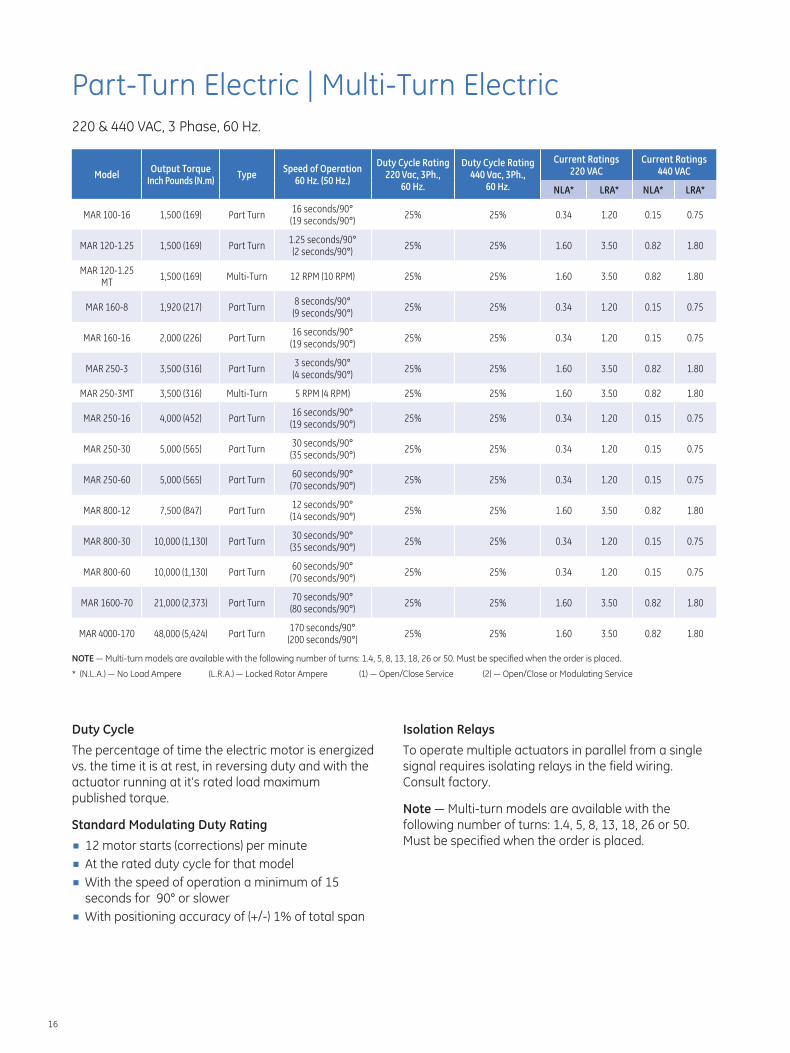
Part-Turn Electric | Multi-Turn Electric 220 & 440 VAC, 3 Phase, 60 Hz.
Model Output Torque
Inch Pounds (N.m) Type
Speed of Operation 60 Hz. (50 Hz.)
Duty Cycle Rating 220 Vac, 3Ph.,
60 Hz.
Duty Cycle Rating 440 Vac, 3Ph.,
60 Hz.
Current Ratings 220 VAC
Current Ratings 440 VAC
NLA* LRA* NLA* LRA*
MAR 100-16 1,500 (169) Part Turn 16 seconds/90° (19 seconds/90°)
25% 25% 0.34 1.20 0.15 0.75
MAR 120-1.25 1,500 (169) Part Turn 1.25 seconds/90° (2 seconds/90°)
25% 25% 1.60 3.50 0.82 1.80
MAR 120-1.25 MT
1,500 (169) Multi-Turn 12 RPM (10 RPM) 25% 25% 1.60 3.50 0.82 1.80
MAR 160-8 1,920 (217) Part Turn 8 seconds/90° (9 seconds/90°)
25% 25% 0.34 1.20 0.15 0.75
MAR 160-16 2,000 (226) Part Turn 16 seconds/90° (19 seconds/90°)
25% 25% 0.34 1.20 0.15 0.75
MAR 250-3 3,500 (316) Part Turn 3 seconds/90° (4 seconds/90°)
25% 25% 1.60 3.50 0.82 1.80
MAR 250-3MT 3,500 (316) Multi-Turn 5 RPM (4 RPM) 25% 25% 1.60 3.50 0.82 1.80
MAR 250-16 4,000 (452) Part Turn 16 seconds/90° (19 seconds/90°)
25% 25% 0.34 1.20 0.15 0.75
MAR 250-30 5,000 (565) Part Turn 30 seconds/90° (35 seconds/90°)
25% 25% 0.34 1.20 0.15 0.75
MAR 250-60 5,000 (565) Part Turn 60 seconds/90° (70 seconds/90°)
25% 25% 0.34 1.20 0.15 0.75
MAR 800-12 7,500 (847) Part Turn 12 seconds/90° (14 seconds/90°)
25% 25% 1.60 3.50 0.82 1.80
MAR 800-30 10,000 (1,130) Part Turn 30 seconds/90° (35 seconds/90°)
25% 25% 0.34 1.20 0.15 0.75
MAR 800-60 10,000 (1,130) Part Turn 60 seconds/90° (70 seconds/90°)
25% 25% 0.34 1.20 0.15 0.75
MAR 1600-70 21,000 (2,373) Part Turn 70 seconds/90° (80 seconds/90°)
25% 25% 1.60 3.50 0.82 1.80
170 seconds/90°MAR 4000-170 48,000 (5,424) Part Turn 25% 25% 1.60 3.50 0.82 1.80
(200 seconds/90°)
NOTE — Multi-turn models are available with the following number of turns: 1.4, 5, 8, 13, 18, 26 or 50. Must be specified when the order is placed.
* (N.L.A.) — No Load Ampere (L.R.A.) — Locked Rotor Ampere (1) — Open/Close Service (2) — Open/Close or Modulating Service
Duty Cycle Isolation Relays
The percentage of time the electric motor is energized To operate multiple actuators in parallel from a single vs. the time it is at rest, in reversing duty and with the signal requires isolating relays in the field wiring. actuator running at it’s rated load maximum Consult factory.published torque.
Note — Multi-turn models are available with the Standard Modulating Duty Rating following number of turns: 1.4, 5, 8, 13, 18, 26 or 50.
■ Must be specified when the order is placed.12 motor starts (corrections) per minute ■ At the rated duty cycle for that model ■ With the speed of operation a minimum of 15
seconds for 90° or slower ■ With positioning accuracy of (+/-) 1% of total span
16
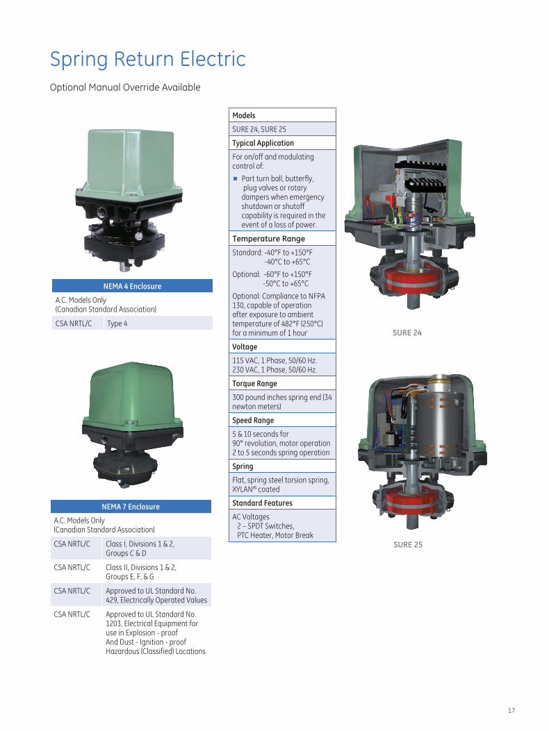
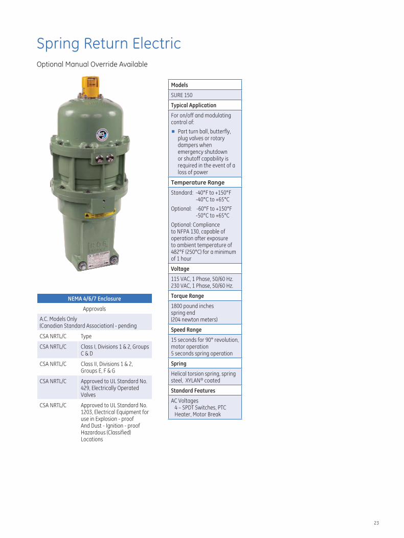
Spring Return Electric Optional Manual Override Available
NEMA 4 Enclosure
Models
SURE 24, SURE 25
Typical Application
For on/off and modulating control of:
■ Part turn ball, butterfly, plug valves or rotary dampers when emergency shutdown or shutoff capability is required in the event of a loss of power.
Temperature Range
Standard: -40°F to +150°F -40°C to +65°C
Optional: -60°F to +150°F -50°C to +65°C
Optional: Compliance to NFPA 130, capable of operation after exposure to ambient temperature of 482°F (250°C) for a minimum of 1 hour
Voltage
115 VAC, 1 Phase, 50/60 Hz. 230 VAC, 1 Phase, 50/60 Hz.
Torque Range
300 pound inches spring end (34 newton meters)
Speed Range
5 & 10 seconds for 90° revolution, motor operation 2 to 5 seconds spring operation
Spring
Flat, spring steel torsion spring, XYLAN® coated
Standard Features
AC Voltages 2 – SPDT Switches, PTC Heater, Motor Break
A.C. Models Only (Canadian Standard Association)
CSA NRTL/C Type 4 SURE 24
NEMA 7 Enclosure
A.C. Models Only (Canadian Standard Association)
CSA NRTL/C Class I, Divisions 1 & 2, Groups C & D
SURE 25
CSA NRTL/C Class II, Divisions 1 & 2, Groups E, F, & G
CSA NRTL/C Approved to UL Standard No. 429, Electrically Operated Values
CSA NRTL/C Approved to UL Standard No. 1203, Electrical Equipment for use in Explosion - proof And Dust - Ignition - proof Hazardous (Classified) Locations
17
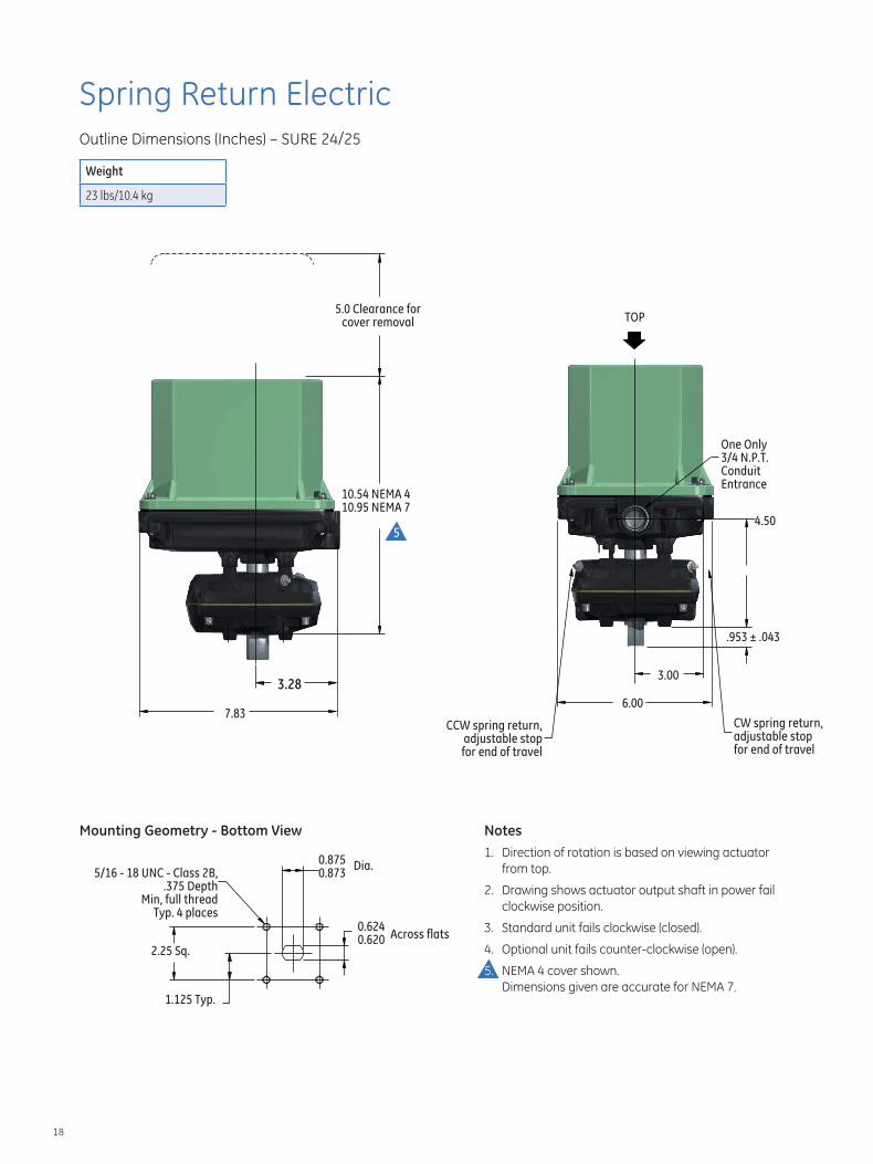
Spring Return Electric Outline Dimensions (Inches) – SURE 24/25
Weight
23 lbs/10.4 kg
5.0 Clearance for TOPcover removal
7.83
3.28
10.54 NEMA 4 10.95 NEMA 7
5
One Only 3/4 N.P.T. Conduit Entrance
4.50
3.00
6.00
.953 ± .043
CW spring return,CCW spring return, adjustable stopadjustable stop for end of travelfor end of travel
Mounting Geometry - Bottom View Notes 1. Direction of rotation is based on viewing actuator
0.875 0.873
Dia. from top. 5/16 - 18 UNC - Class 2B, .375 Depth 2. Drawing shows actuator output shaft in power fail
Min, full thread clockwise position. Typ. 4 places 0.624 3. Standard unit fails clockwise (closed). Across flats0.620
4. Optional unit fails counter-clockwise (open).
5. NEMA 4 cover shown. Dimensions given are accurate for NEMA 7.
2.25 Sq.
1.125 Typ.
18
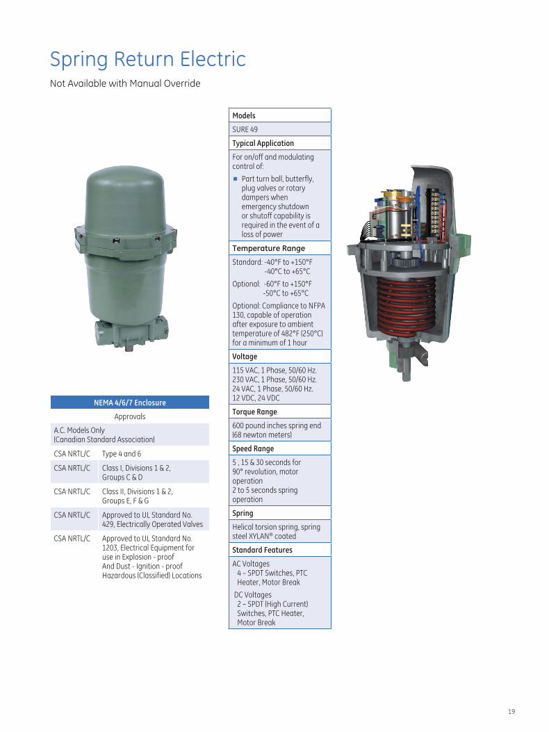
Spring Return Electric Not Available with Manual Override
NEMA 4/6/7 Enclosure
Approvals
A.C. Models Only (Canadian Standard Association)
CSA NRTL/C Type 4 and 6
CSA NRTL/C Class I, Divisions 1 & 2, Groups C & D
CSA NRTL/C Class II, Divisions 1 & 2, Groups E, F & G
CSA NRTL/C Approved to UL Standard No. 429, Electrically Operated Valves
CSA NRTL/C Approved to UL Standard No. 1203, Electrical Equipment for use in Explosion - proof And Dust - Ignition - proof Hazardous (Classified) Locations
Models
SURE 49
Typical Application
For on/off and modulating control of:
■ Part turn ball, butterfly, plug valves or rotary dampers when emergency shutdown or shutoff capability is required in the event of a loss of power
Temperature Range
Standard: -40°F to +150°F -40°C to +65°C
Optional: -60°F to +150°F -50°C to +65°C
Optional: Compliance to NFPA 130, capable of operation after exposure to ambient temperature of 482°F (250°C) for a minimum of 1 hour
Voltage
115 VAC, 1 Phase, 50/60 Hz. 230 VAC, 1 Phase, 50/60 Hz. 24 VAC, 1 Phase, 50/60 Hz. 12 VDC, 24 VDC
Torque Range
600 pound inches spring end (68 newton meters)
Speed Range
5 , 15 & 30 seconds for 90° revolution, motor operation 2 to 5 seconds spring operation
Spring
Helical torsion spring, spring steel XYLAN® coated
Standard Features
AC Voltages 4 – SPDT Switches, PTC Heater, Motor Break
DC Voltages 2 – SPDT (High Current) Switches, PTC Heater, Motor Break
19
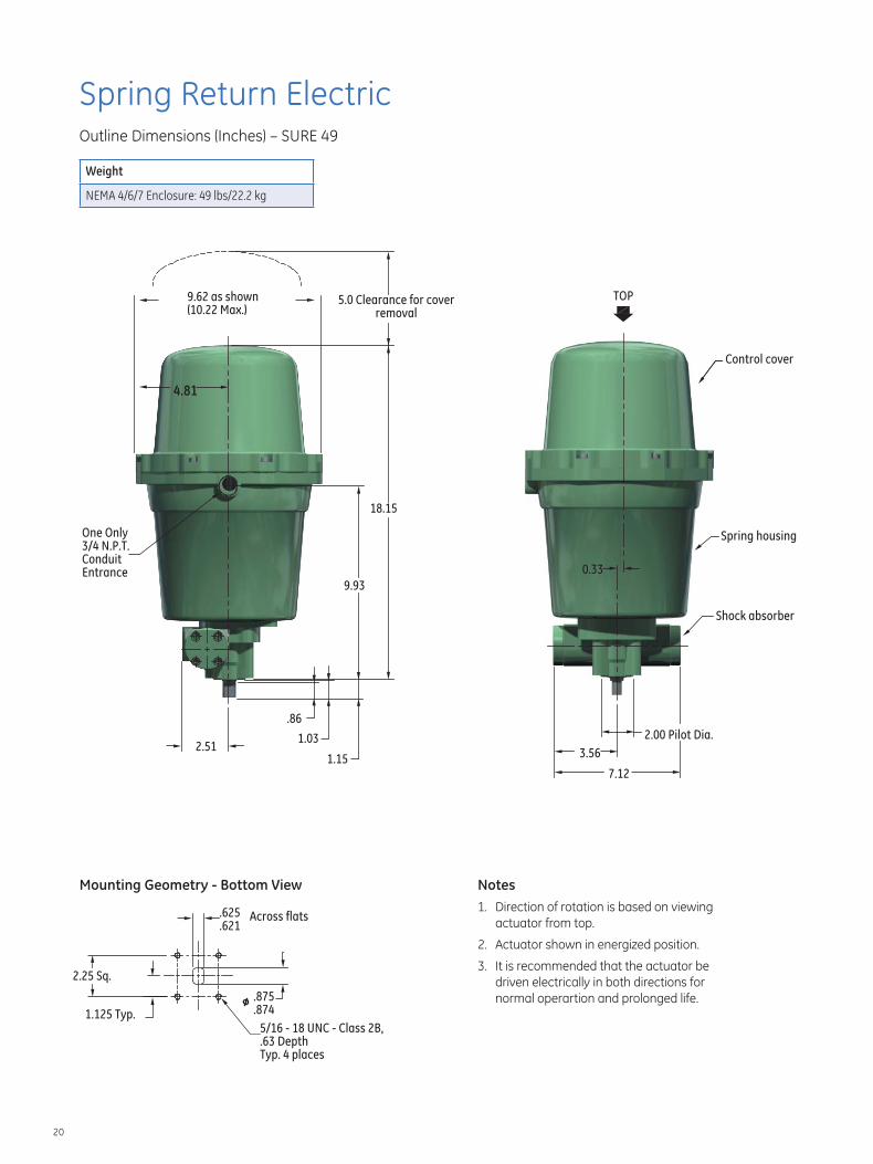
Spring Return Electric Outline Dimensions (Inches) – SURE 49
Weight
NEMA 4/6/7 Enclosure: 49 lbs/22.2 kg
9.62 as shown (10.22 Max.)
4.81
18.15
9.93
.86
1.15 2.51
1.03
TOP5.0 Clearance for cover removal
0.33
Control cover
One Only Spring housing3/4 N.P.T. Conduit Entrance
Shock absorber
2.00 Pilot Dia.
3.56
7.12
Across flats.625 .621
2.25 Sq.
.875
.8741.125 Typ.
Mounting Geometry - Bottom View Notes 1. Direction of rotation is based on viewing
actuator from top.
2. Actuator shown in energized position.
3. It is recommended that the actuator be driven electrically in both directions for normal operartion and prolonged life.
5/16 - 18 UNC - Class 2B, .63 Depth Typ. 4 places
20
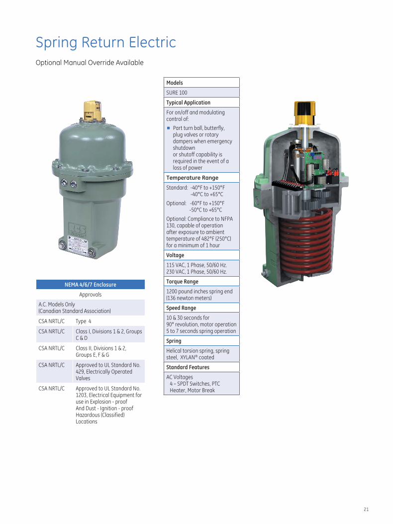
Spring Return Electric Optional Manual Override Available
NEMA 4/6/7 Enclosure
Approvals
A.C. Models Only (Canadian Standard Association)
CSA NRTL/C Type 4
CSA NRTL/C Class I, Divisions 1 & 2, Groups C & D
CSA NRTL/C Class II, Divisions 1 & 2, Groups E, F & G
CSA NRTL/C Approved to UL Standard No. 429, Electrically Operated Valves
CSA NRTL/C Approved to UL Standard No. 1203, Electrical Equipment for use in Explosion - proof And Dust - Ignition - proof Hazardous (Classified) Locations
Models
SURE 100
Typical Application
For on/off and modulating control of:
■ Part turn ball, butterfly, plug valves or rotary dampers when emergency shutdown or shutoff capability is required in the event of a loss of power
Temperature Range
Standard: -40°F to +150°F -40°C to +65°C
Optional: -60°F to +150°F -50°C to +65°C
Optional: Compliance to NFPA 130, capable of operation after exposure to ambient temperature of 482°F (250°C) for a minimum of 1 hour
Voltage
115 VAC, 1 Phase, 50/60 Hz. 230 VAC, 1 Phase, 50/60 Hz.
Torque Range
1200 pound inches spring end (136 newton meters)
Speed Range
10 & 30 seconds for 90° revolution, motor operation 5 to 7 seconds spring operation
Spring
Helical torsion spring, spring steel, XYLAN® coated
Standard Features
AC Voltages 4 – SPDT Switches, PTC Heater, Motor Break
21
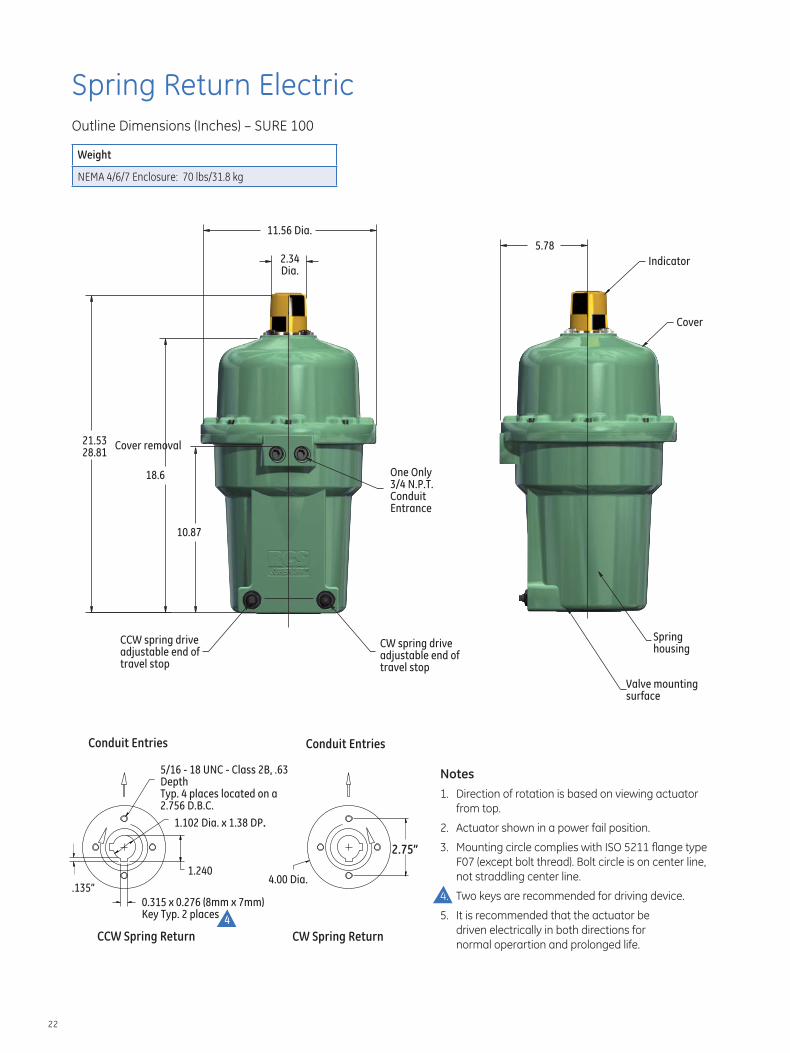
Spring Return Electric Outline Dimensions (Inches) – SURE 100
Weight
NEMA 4/6/7 Enclosure: 70 lbs/31.8 kg
21.53 28.81
11.56 Dia.
2.34 Dia.
CCW spring drive adjustable end of travel stop
Cover removal
18.6
10.87
Conduit Entries
5/16 - 18 UNC - Class 2B, .63
Typ. 4 places located on a 2.756 D.B.C.
1.102 Dia. x 1.38 DP.
Depth
.135”
1.240
0.315 x 0.276 (8mm x 7mm) Key Typ. 2 places
4
CCW Spring Return
Cover
One Only 3/4 N.P.T. Conduit Entrance
CW spring drive adjustable end of travel stop
Conduit Entries
4.00 Dia.
2.75”
Notes 1. Direction of rotation is based on viewing actuator from top.
2. Actuator shown in a power fail position.
3. Mounting circle complies with ISO 5211 flange type F07 (except bolt thread). Bolt circle is on center line, not straddling center line.
4. Two keys are recommended for driving device.
5. It is recommended that the actuator be driven electrically in both directions for
CW Spring Return normal operartion and prolonged life.
5.78
Indicator
Spring housing
Valve mounting surface
22
Spring Return Electric Optional Manual Override Available
NEMA 4/6/7 Enclosure
Approvals
A.C. Models Only (Canadian Standard Association) - pending
CSA NRTL/C Type
CSA NRTL/C Class I, Divisions 1 & 2, Groups C & D
CSA NRTL/C Class II, Divisions 1 & 2, Groups E, F & G
CSA NRTL/C Approved to UL Standard No. 429, Electrically Operated Valves
CSA NRTL/C Approved to UL Standard No. 1203, Electrical Equipment for use in Explosion - proof And Dust - Ignition - proof Hazardous (Classified) Locations
Models
SURE 150
Typical Application
For on/off and modulating control of:
■ Part turn ball, butterfly, plug valves or rotary dampers when emergency shutdown or shutoff capability is required in the event of a loss of power
Temperature Range
Standard: -40°F to +150°F -40°C to +65°C
Optional: -60°F to +150°F -50°C to +65°C
Optional: Compliance to NFPA 130, capable of operation after exposure to ambient temperature of 482°F (250°C) for a minimum of 1 hour
Voltage
115 VAC, 1 Phase, 50/60 Hz. 230 VAC, 1 Phase, 50/60 Hz.
Torque Range
1800 pound inches spring end (204 newton meters)
Speed Range
15 seconds for 90° revolution, motor operation 5 seconds spring operation
Spring
Helical torsion spring, spring steel, XYLAN® coated
Standard Features
AC Voltages 4 – SPDT Switches, PTC Heater, Motor Break
23
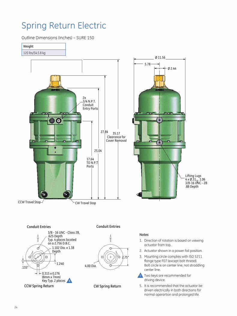
Spring Return Electric Outline Dimensions (Inches) – SURE 150
Weight
120 lbs/54.5.8 kg
27.84
2x 3/4 N.P.T. Conduit Entry Ports
CCW Travel Stop
25.04
CW Travel Stop
17.64 TO N.P.T. Ports
35.17 Clearance for
Cover Removal
Lifting Lugs 4 x Ø.31 1.06 3/8-16 UNC - 2B .88 Depth
Ø 11.56
5.78
Ø 2.44
Conduit Entries Conduit Entries
CCW Spring Return CW Spring Return
Direction of rotation is based on viewing actuator from top.
Actuator shown in a power fail position.
Mounting circle complies with ISO 5211 flange type F07 (except bolt thread).
Bolt circle is on center line, not straddling center line.
Two keys are recommended for driving device.
5. It is recommended that the actuator be driven electrically in both directions for normal operartion and prolonged life.
Notes
1.
2.
3.
4.
3/8 - 16 UNC - Class 2B, .625 Depth Typ. 4 places located on a 2.756 D.B.C.
.135”
1.102 Dia. x 1.38 Depth
1.240 4.00 Dia.
2.75”
0.315 x 0.276 (8mm x 7mm) Key Typ. 2 places 4
24
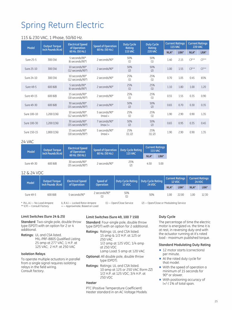
Spring Return Electric 115 & 230 VAC, 1 Phase, 50/60 Hz.
Model Output Torque
Inch Pounds (N.m)
Electrical Speed of Operation 60 Hz. (50 Hz.)
Speed of Operation 60 Hz. (50 Hz.)
Duty Cycle Rating
115 VAC
Duty Cycle Rating
220 VAC
Current Ratings 115 VAC
Current Ratings 220 VAC
NLA* LRA* NLA* LRA*
Sure 25-5 300 (34) 5 seconds/90° (6 seconds/90°)
2 seconds/90° 50% (1)
50% (1)
1.40 2.15 CF** CF**
Sure 25-10 300 (34) 10 seconds/90° (12 seconds/90°)
2 seconds/90° 50% (2)
50% (2)
1.00 1.55 CF** CF**
Sure 24-10 300 (34) 10 seconds/90° (12 seconds/90°)
2 seconds/90° 25% (1)
25% (1)
0.70 1.05 0.45 65%
Sure 49-5 600 (68) 5 seconds/90° (6 seconds/90°)
2 seconds/90° 25% (1)
25% (1)
1.10 1.80 1.00 1.20
Sure 49-15 600 (68) 15 seconds/90° (18 seconds/90°)
2 seconds/90° 25% (1)
25% (1)
0.55 1.55 0.35 0.90
Sure 49-30 600 (68) 30 seconds/90° (35 seconds/90°)
2 seconds/90° 50% (2)
50% (2)
0.65 0.70 0.30 0.35
Sure 100-10 1,200 (136) 10 seconds/90° (12 seconds/90°)
5 seconds/90° (max) +
25% (1)
25% (1)
1.90 2.90 0.90 1.35
Sure 100-30 1,200 (136) 30 seconds/90° (35 seconds/90°)
7 seconds/90° (max ) +
50% (2)
50% (2)
0.65 0.95 0.35 0.45
15 seconds/90°Sure 150-15 1,800 (136)
(18 seconds/90°)
24 VAC
5 seconds/90° (max) +
25% (1), (2)
25% (1), (2)
1.90 2.90 0.90 1.35
Model Output Torque
Inch Pounds (N.m)
Electrical Speed of Operation 60 Hz. (50 Hz.)
Speed of Operation 60 Hz. (50 Hz.)
Duty Cycle Rating 115 VAC
Current Ratings 115 VAC
NLA* LRA*
30 seconds/90° 25%Sure 49-30 600 (68) 2 seconds/90° 4.50 5.00
(35 seconds/90°) (2)
12 & 24 VDC
Model Output Torque
Inch Pounds (N.m) Electrical Speed
of Operation Speed of
Operation Duty Cycle Rating
12 VDC Duty Cycle Rating
24 VDC
Current Ratings 12 VDC
Current Ratings 24 VDC
NLA* LRA* NLA* LRA*
Sure 49-5 600 (68) 5 seconds/90° 2 seconds/90°
(1) 50% (1)
50% 1.00 22.00 1.00 12.30
* (N.L.A.) — No Load Ampere (L.R.A.) — Locked Rotor Ampere (1) — Open/Close Service (2) — Open/Close or Modulating Service ** (CF) — Consult Factory + — Approximate, Based on Load
Limit Switches (Sure 24 & 25) Standard: Two-single pole, double throw type (SPDT) with an option for 2 or 4 additional.
Ratings: UL and CSA listed. MIL-PRF-8805 Qualified Listing 25 amp at 277 VAC; 1 H.P. at 125 VAC; 2 H.P. at 250 VAC
Isolation Relays To operate multiple actuators in parallel from a single signal requires isolating relays in the field wiring. Consult factory.
Limit Switches (Sure 49, 100 7 150) Standard: Four-single pole, double throw type (SPDT) with an option for 2 additional.
Ratings: Ratings: UL and CSA listed. 15 amp & 1/2 H.P. at 125 or
250 VAC 1/2 amp at 125 VDC; 1/4 amp at 250 VDC Lamp Load: 5 amp at 120 VAC
Optional: All double pole, double throw type (DPDT).
Ratings: Ratings: UL and CSA listed. 10 amp at 125 or 250 VAC (form ZZ) 1/2 H.P. at 125 VDC; 3/4 H.P. at
250 VDC
Heater PTC (Positive Temperature Coefficient) Heater standard in an AC Voltage Models
Duty Cycle The percentage of time the electric motor is energized vs. the time it is at rest, in reversing duty and with the actuator running at it’s rated load - maximum published torque.
Standard Modulating Duty Rating ■ 12 motor starts (corrections)
per minute. ■ At the rated duty cycle for
that model. ■ With the speed of operation a
minimum of 15 seconds for 90° or slower.
■ With positioning accuracy of (+/-) 1% of total span.
25
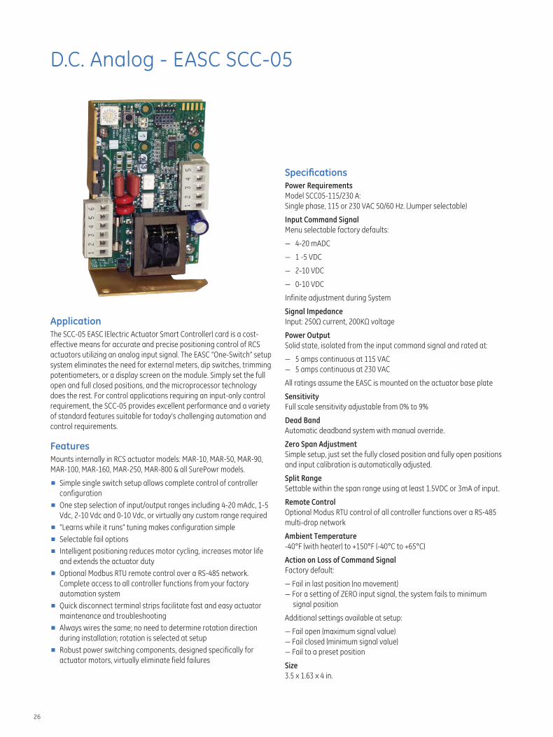
D.C. Analog - EASC SCC-05
Application The SCC-05 EASC (Electric Actuator Smart Controller) card is a cost-
effective means for accurate and precise positioning control of RCS
actuators utilizing an analog input signal. The EASC “One-Switch” setup
system eliminates the need for external meters, dip switches, trimming
potentiometers, or a display screen on the module. Simply set the full
open and full closed positions, and the microprocessor technology
does the rest. For control applications requiring an input-only control
requirement, the SCC-05 provides excellent performance and a variety
of standard features suitable for today’s challenging automation and
control requirements.
Features Mounts internally in RCS actuator models: MAR-10, MAR-50, MAR-90,
MAR-100, MAR-160, MAR-250, MAR-800 & all SurePowr models.
■ Simple single switch setup allows complete control of controller
configuration
■ One step selection of input/output ranges including 4-20 mAdc, 1-5
Vdc, 2-10 Vdc and 0-10 Vdc, or virtually any custom range required
■ “Learns while it runs” tuning makes configuration simple
■ Selectable fail options
■ Intelligent positioning reduces motor cycling, increases motor life
and extends the actuator duty
■ Optional Modbus RTU remote control over a RS-485 network.
Complete access to all controller functions from your factory
automation system
■ Quick disconnect terminal strips facilitate fast and easy actuator
maintenance and troubleshooting
■ Always wires the same; no need to determine rotation direction
during installation; rotation is selected at setup
■ Robust power switching components, designed specifically for
actuator motors, virtually eliminate field failures
Specifi cations Power Requirements
Model SCC05-115/230 A:
Single phase, 115 or 230 VAC 50/60 Hz. (Jumper selectable)
Input Command Signal
Menu selectable factory defaults:
— 4-20 mADC
— 1 -5 VDC
— 2-10 VDC
— 0-10 VDC
Infinite adjustment during System
Signal Impedance
Input: 250Ω current, 200KΩ voltage
Power Output
Solid state, isolated from the input command signal and rated at:
— 5 amps continuous at 115 VAC
— 5 amps continuous at 230 VAC
All ratings assume the EASC is mounted on the actuator base plate
Sensitivity
Full scale sensitivity adjustable from 0% to 9%
Dead Band
Automatic deadband system with manual override.
Zero Span Adjustment
Simple setup, just set the fully closed position and fully open positions
and input calibration is automatically adjusted.
Split Range
Settable within the span range using at least 1.5VDC or 3mA of input.
Remote Control
Optional Modus RTU control of all controller functions over a RS-485
multi-drop network
Ambient Temperature
-40°F (with heater) to +150°F (-40°C to +65°C)
Action on Loss of Command Signal
Factory default:
— Fail in last position (no movement)
— For a setting of ZERO input signal, the system fails to minimum
signal position
Additional settings available at setup:
— Fail open (maximum signal value)
— Fail closed (minimum signal value)
— Fail to a preset position
Size
3.5 x 1.63 x 4 in.
26
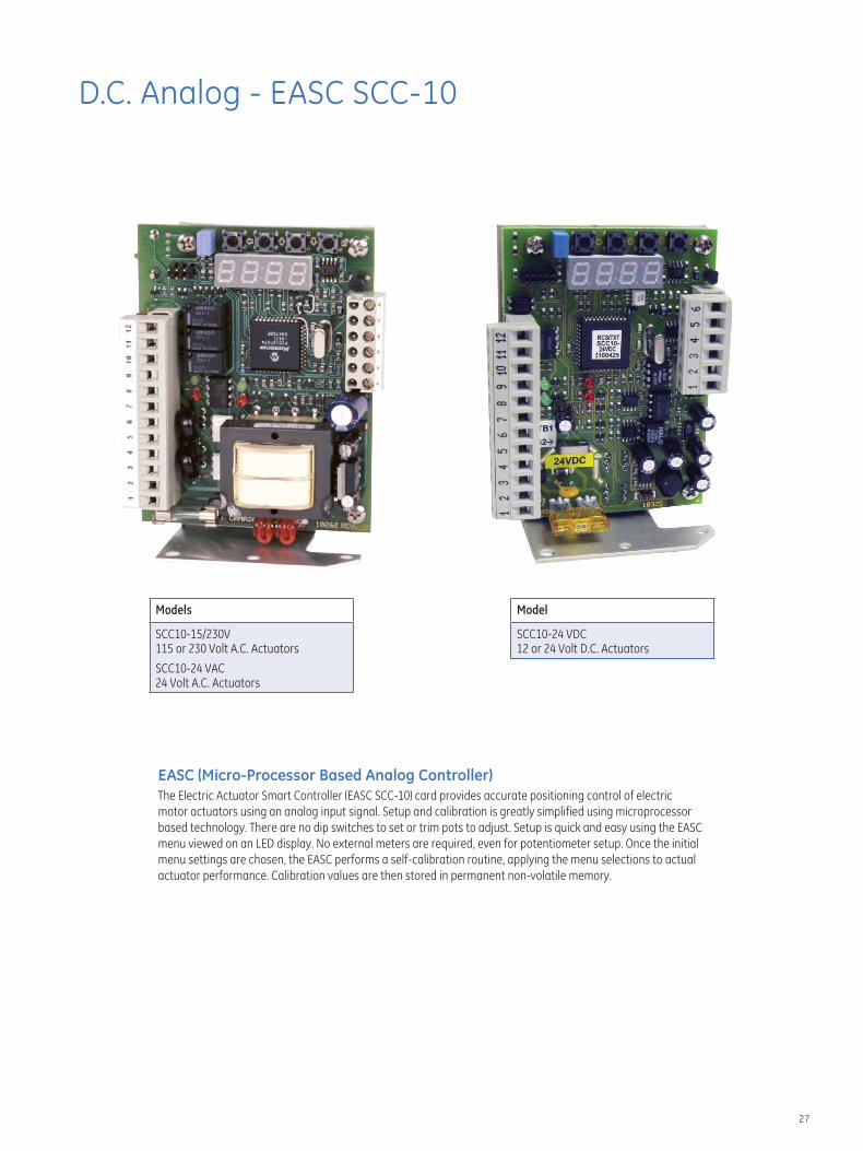
D.C. Analog - EASC SCC-10
Models
SCC10-15/230V 115 or 230 Volt A.C. Actuators
SCC10-24 VAC 24 Volt A.C. Actuators
Model
SCC10-24 VDC 12 or 24 Volt D.C. Actuators
EASC (Micro-Processor Based Analog Controller) The Electric Actuator Smart Controller (EASC SCC-10) card provides accurate positioning control of electric
motor actuators using an analog input signal. Setup and calibration is greatly simplified using microprocessor
based technology. There are no dip switches to set or trim pots to adjust. Setup is quick and easy using the EASC
menu viewed on an LED display. No external meters are required, even for potentiometer setup. Once the initial
menu settings are chosen, the EASC performs a self-calibration routine, applying the menu selections to actual
actuator performance. Calibration values are then stored in permanent non-volatile memory.
27
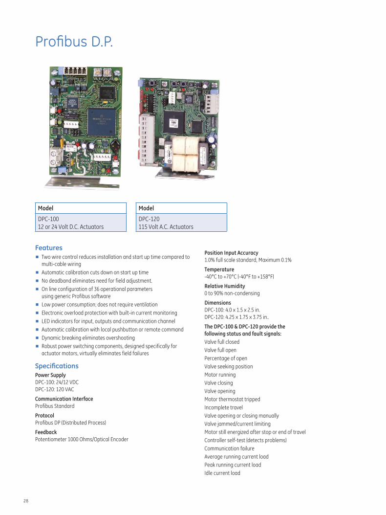
Profi bus D.P.
Model
DPC-100
12 or 24 Volt D.C. Actuators
Model
DPC-120
115 Volt A.C. Actuators
Features ■ Two wire control reduces installation and start up time compared to
multi-cable wiring
■ Automatic calibration cuts down on start up time
■ No deadband eliminates need for field adjustment.
■ On line configuration of 36 operational parameters
using generic Profibus software
■ Low power consumption; does not require ventilation
■ Electronic overload protection with built-in current monitoring
■ LED indicators for input, outputs and communication channel
■ Automatic calibration with local pushbutton or remote command
■ Dynamic breaking eliminates overshooting
■ Robust power switching components, designed specifically for
actuator motors, virtually eliminates field failures
Specifi cations Power Supply
DPC-100: 24/12 VDC
DPC-120: 120 VAC
Communication Interface
Profibus Standard
Protocol
Profibus DP (Distributed Process)
Feedback
Potentiometer 1000 Ohms/Optical Encoder
Position Input Accuracy
1.0% full scale standard, Maximum 0.1%
Temperature
-40°C to +70°C (-40°F to +158°F)
Relative Humidity
0 to 90% non-condensing
Dimensions
DPC-100: 4.0 x 1.5 x 2.5 in.
DPC-120: 4.25 x 1.75 x 3.75 in..
The DPC-100 & DPC-120 provide the
following status and fault signals:
Valve full closed
Valve full open
Percentage of open
Valve seeking position
Motor running
Valve closing
Valve opening
Motor thermostat tripped
Incomplete travel
Valve opening or closing manually
Valve jammed/current limiting
Motor still energized after stop or end of travel
Controller self-test (detects problems)
Communication failure
Average running current load
Peak running current load
Idle current load
28
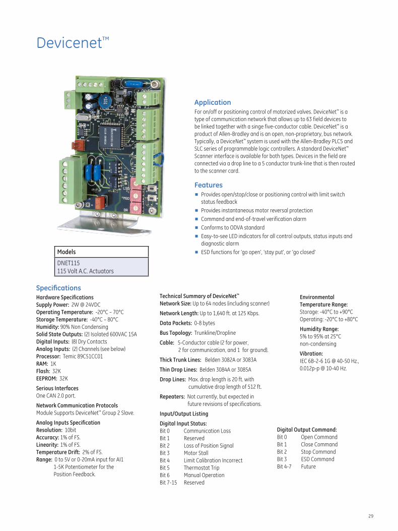
Devicenet™
Application For on/off or positioning control of motorized valves. DeviceNet™ is a
type of communication network that allows up to 63 field devices to
be linked together with a singe five-conductor cable. DeviceNet™ is a
product of Allen-Bradley and is an open, non-proprietary, bus network.
Typically, a DeviceNet™ system is used with the Allen-Bradley PLC5 and
SLC series of programmable logic controllers. A standard DeviceNet™
Scanner interface is available for both types. Devices in the field are
connected via a drop line to a 5 conductor trunk-line that is then routed
to the scanner card.
Features ■ Provides open/stop/close or positioning control with limit switch
status feedback
■ Provides instantaneous motor reversal protection
■ Command and end-of-travel verification alarm
■ Conforms to ODVA standard
■ Easy-to-see LED indicators for all control outputs, status inputs and
Models
DNET115
115 Volt A.C. Actuators
Specifi cations Hardware Specifications
Supply Power: 2W @ 24VDC
Operating Temperature: -20°C – 70°C
Storage Temperature: -40°C – 80°C
Humidity: 90% Non Condensing
Solid State Outputs: (2) Isolated 600VAC 15A
Digital Inputs: (8) Dry Contacts
Analog Inputs: (2) Channels (see below)
Processor: Temic 89C51CC01
RAM: 1K
Flash: 32K
EEPROM: 32K
Serious Interfaces
One CAN 2.0 port.
Network Communication Protocols
Module Supports DeviceNet™ Group 2 Slave.
Analog Inputs Specification
Resolution: 10bit
Accuracy: 1% of FS.
Linearity: 1% of FS.
Temperature Drift: 2% of FS.
Range: 0 to 5V or 0-20mA input for AI1
1-5K Potentiometer for the
Position Feedback.
diagnostic alarm
■ ESD functions for ‘go open’, ‘stay put’, or ‘go closed’
Technical Summary of DeviceNet™
Network Size: Up to 64 nodes (including scanner)
Network Length: Up to 1,640 ft. at 125 Kbps.
Data Packets: 0-8 bytes
Bus Topology: Trunkline/Dropline
Cable: 5-Conductor cable (2 for power,
2 for communication, and 1 for ground).
Thick Trunk Lines: Belden 3082A or 3083A
Thin Drop Lines: Belden 3084A or 3085A
Drop Lines: Max. drop length is 20 ft. with
cumulative drop length of 512 ft.
Repeaters: Not currently, but expected in
future revisions of specifications.
Input/Output Listing
Digital Input Status:
Bit 0 Communication Loss
Bit 1 Reserved
Bit 2 Loss of Position Signal
Bit 3 Motor Stall
Bit 4 Limit Calibration Incorrect
Bit 5 Thermostat Trip
Bit 6 Manual Operation
Bit 7-15 Reserved
Environmental
Temperature Range:
Storage: -40°C to +90°C
Operating: -20°C to +80°C
Humidity Range:
5% to 95% at 25°C
non-condensing
Vibration:
IEC 6B-2-6 1G @ 40-50 Hz.,
0.012p-p @ 10-40 Hz.
Digital Output Command:
Bit 0 Open Command
Bit 1 Close Command
Bit 2 Stop Command
Bit 3 ESD Command
Bit 4-7 Future
29

Modbus
Features ■ High resolution position input for up to 0.1% accuracy
■ 4-120/240VAC inputs for open and closed limit switches
and 2 general purpose inputs
■ Simple 4-wire Modbus-485 communication
network includes supervisory power
■ Robust communication, up to 500m cable length
■ Plugable terminal strips for easy field installation
■ Direct mounting within the actuator
■ Low power consumption; does not require ventilation
■ Electronic overload protection with built-in current
monitoring optional
■ High power outputs can directly drive small motors
■ LED indicators on inputs, outputs and
communication channel
■ Automatic calibration using local push button or remote
command
■ Multi-vendor PLC support through the standard Modbus
communication module
Typical Applications ■ Blending of bulk materials
■ Petroleum products and other liquids flow control
■ Level control for maintaining process supply
Application The Modbus is an application specific controller, designed for position
ing electric actuators using rotary feedback. Typical devices include
rotary and linear actuators. Feedback may be via a potentiometer or a
quadrature optical encoder. Controller outputs can drive small electric
motors or motor starters directly.
A Modbus-485 communication network allows up to 100 devices on
a single channel. The Modbus is powered by 24VDC and provides four
supervisory inputs, configurable as limit switches or force open/close
signals.
Automatic calibration is provided which requires no loop tuning.
All operating parameters can be set as registers in the Modbus
communications map.
Specifi cations Actuator
Voltage 120/240VAC 1Ø
Current 4A (2 minute 25% duty-cycle)
Fuse GMA 4 replaceable
Supervisory
Voltage 10 to 25VDC
Current 30mA @ 24VDC
Auxiliary Inputs
Voltage 120/240VAC
Current min 10mA / max 20mA
Communication
Standard Modbus-RS485 differential
Distance 500m (1,640ft.)
Input Load 12K ohm, standard
Termination 120Ω balanced line
Position
Resolution 12 bit (1 part in 4096)
Accuracy 0.1% full scale
Potentiometer 1000Ω typical (500 to 10kΩ)
Quadrature
Optical Encoder 1000 to 4096 pulses
Environment
Temperature -40°C to +70°C (-40°F to +158°F)
Relative Humidity 0 to 95% non-condensing
Dimensions
Length 96mm (3.75 in)
Width 70mm (2.75 in)
Height 36mm (1.40 in)
30


GE Energy 16240 Port Northwest Drive Houston, Texas 77041-2645 USA PH: +1 832.590.2306 Toll Free Phone: 800.945.9898 Fax: +1 713.849.2879 Email: [email protected]
Visit us online at: www.ge.com/energy
2011 General Electric Company All Rights Reserved * Denotes trademark of General Electric Company
GEA 19647 RCS Actuators 3.12


![[Rcs Iot] Rcs-e v1-2- Joyn](https://img.pdfslide.us/doc/110x75/577cd0231a28ab9e78917fbc/rcs-iot-rcs-e-v1-2-joyn.jpg)