Embed Size (px)
Citation preview

RCP6/RCP6S/RCP6CR/RCP6SCR Actuator
Slider Type/Rod Type Radial Cylinder/Table Type
Wide Slider Type/Wide Radial Cylinder
First Step Guide Third Edition Thank you for purchasing our product. Make sure to read the Safety Guide and detailed Instruction Manual (DVD) included with the product in addition to this First Step Guide to ensure correct use. This Instruction Manual is original.
• Using or copying all or part of this Instruction Manual without permission is prohibited. • The company names, names of products and trademarks of each company shown in the sentences are registered
trademarks.
Product Check This product is comprised of the following parts if it is of standard configuration. If you find any fault in the contained model or any missing parts, contact us or our distributor.
1. Parts (The option is excluded.) No. Part Name Model Quantity Remarks
1 Actuator Main Body Refer to How to read the model No. 1
Accessories 2 Motor • Encoder Cable
(Note 1) 1
3 Home Position Marking Sticker 1
Packaged in slider type, table type and wide slider type.
4 Nut Packaged in rod type and Radial Cylinder. Refer to list below.
5 Square Nut 1 set Packaged in rod type. Refer to list below.
6 First Step Guide 1 7 Instruction Manual (DVD) 1 8 Safety Guide 1
Note 1 Please refer to the wiring layout for the enclosed motor・encoder cables. (List of Included Nut Type)
Nut (M10×1.25) Nut (M14×1.5) Nut (M20×1.5) RA4C, RA4R, RA6C, RA6R, RRA4C, RRA4R, RRA6C, RRA6R
1
RA7C, RA7R, RRA7C, RRA7R 1
RA8C, RA8R, RRA8C, RRA8R 1
[Refer to of the instruction manual 6. External Dimensions for the dimensions of nuts.] The square nut will be enclosed for rod type. However, it will not be enclosed when the T-slot nut bar (model code: NTB) has been selected as an option.
Square Nut (7×7 M4) Square Nut (10×10 M6) Square Nut (13×13 M8) RA4C, RA4R 4 RA6C, RA6R 4 RA7C, RA7R 8 RA8C, RA8R 8
2. How to Read the Model Plate
3. How to Read the Model No. 3.1 Slider Type
RCP6 –SA4C –WA –35P –2.5 –50 –P3 –P –B –**
3.2 Rod Type
RCP6 –RA4C –WA –35P –2.5 –50 –P3 –P –B –**
3.3 Radial Cylinder RCP6 –RRA4C –WA –35P –2.5 –60 –P3 –P –B –**
3.4 Table Type RCP6 –TA4C –WA –35P –2.5 –50 –P3 –P –B –**
3.5 Wide Slider Type
RCP6 –WSA10C –WA –35P –2.5 –50 –P3 –P –B –**
3.6 Wide Radial Cylinder
RCP6 –WRA10C –WA –35P –2.5 –50 –P3 –P –B –**
Warning : Operation of this equipment requires detailed installation and operation instructions which are provided on the DVD Manual included in the box this device was packaged in. It should be retained with this device at all times.
A hard copy of Manual can be requested by contacting your nearest IAI Sales Office listed at the back cover of the Instruction Manual or on the First Step Guide.
MODEL RCP6-SA4C-WA-35P-2.5-50-P3-P-B SERIAL No.100090267 MADE IN JAPAN
Model Serial number
<Series name> Standard spec.
RCP6 Built-in controller spec.
RCP6S Cleanroom type
Standard Specification RCP6CR
Cleanroom type Built-in controller spec. RCP6SCR
<Type> Motor straight type
SA4C, SA6C, SA7C, SA8C
Motor reversing type SA4R, SA6R, SA7R, SA8R
<Encoder type> WA: Battery-less absolute
<Motor type> 35P : 35□ size 42P : 42□ size 56P : 56□ size 56SP : 56□ size
<Lead> SA4C, SA4R
2.5/5/10/16 SA6C, SA6R
3/6/12/20 SA7C, SA7R
4/8/16/24 SA8C, SA8R
5/10/20/30
Identification for IAI use only (Note 1)
<Options> B : Brake NM : Reversed-home specification HPR : High-precision specification ML : Motor left reversed (Standard) MR : Motor right reversed CJT : Cable exit direction changed (Top) CJR : Cable exit direction changed (Right) CJL : Cable exit direction changed (Left) CJB : Cable exit direction changed
(Bottom) CJO : Cable eject direction changed
(Outside) SS : Slider spacer SR : Slider part roller type W : Double slider type VR : Vacuum joint attachment in opposite
<Cable length> N : None P : 1m S : 3m M : 5m X□□ : Length specification R□□ : Robot cable
Standard spec. <Controller>
P3 : PCON-CB, MCON, MSEL P4 : PCON-CFB
Built-in controller spec. <I/O type>
SE : SIO type <Stroke>
[Refer to 1.2 Specifications of the Instruction Manual]
<Series name> Externally Mounted Controller
RCP6 Built-in controller
RCP6S <Type>
Motor straight type RA4C, RA6C, RA7C, RA8C
Motor reversing type RA4R, RA6R, RA7R, RA8R
<Encoder type> WA: Battery-less absolute
<Motor type> 35P : 35□ size 42P : 42□ size 56P : 56□ size 60P : 60□ size
<Lead> RA4C, RA4R
2.5/5/10/16 RA6C, RA6R
3/6/12/20 RA7C, RA7R
4/8/16/24 RA8C, RA8R
5/10/20 <Stroke>
[Refer to 1.2 Specifications of the Instruction Manual]
Identification for IAI use only (Note 1)
<Options> B : Brake NM : Reversed-home specification FL : Flange bracket FT : Foot bracket NTB : T-slot nut bar specification NFA : Tip adapter (Internal thread) ML : Motor left reversed (Standard) MR : Motor right reversed MT : Motor top reversed CJT : Cable exit direction changed (Top) CJR : Cable exit direction changed (Right) CJL : Cable exit direction changed (Left) CJB : Cable exit direction changed
(Bottom) CJO : Cable exit direction changed
(Outside) <Cable length>
N : None P : 1m S : 3m M : 5m X□□ : Length specification R□□ : Robot cable
Standard spec. <Controller>
P3 : PCON-CB, MCON, MSEL P4 : PCON-CFB
Built-in controller spec. <I/O type>
SE: SIO type
<Series name> Standard spec.
RCP6 Built-in controller spec.
RCP6S <Type>
Motor straight type RRA4C, RRA6C, RRA7C, RRA8C
Motor reversing type RRA4R, RRA6R, RRA7R, RRA8R
<Encoder type> WA: Battery-less absolute
<Motor type> 35P : 35□ size 42P : 42□ size 56P : 56□ size 60P : 60□ size
<Lead> RRA4C, RRA4R
2.5/5/10/16 RRA6C, RRA6R
3/6/12/20 RRA7C, RRA7R
4/8/16/24 RRA8C, RRA8R
5/10/20 <Stroke>
[Refer to 1.2 Specifications of the Instruction Manual]
Identification for IAI use only (Note 1)
<Options> B : Brake NM : Reversed-home specification FL : Flange bracket FFA : Tip adapter (Flange) (Note3) NFA : Tip adapter (Internal Thread) KFA : Tip adapter (Keyway) (Note3) NJ : Knuckle Joint (Note2) QR : Clevis (Note2) ML : Motor left reversed (Standard) MR : Motor right reversed CJT : Cable exit direction changed (Top) CJR : Cable exit direction changed (Right) CJL : Cable exit direction changed (Left) CJB : Cable exit direction changed
(Bottom) CJO : Cable exit direction changed
(Outside) <Cable length>
N : None P : 1m S : 3m M : 5m X□□ : Length specification R□□ : Robot cable
Standard spec. <Controller>
P3 : PCON-CB, MCON, MSEL P4 : PCON-CFB
Built-in controller spec. <I/O type>
SE: SIO type
<Series name> Standard spec.
RCP6 Built-in controller spec.
RCP6S <Type>
Motor straight type TA4C, TA6C, TA7C
Motor reversing type TA4R, TA6R, TA7R
<Encoder type> WA: Battery-less absolute
<Motor type> 35P : 35□ size 42P : 42□ size 56P : 56□ size
<Lead> TA4C, TA4R
2.5/5/10/16 TA4C, TA4R (Double-guided block)
2.5/5/10 TA6C, TA6R
3/6/12/20 TA6C, TA6R (Double-guided block)
3/6/12 TA7C, TA7R
4/8/16/24 TA7C, TA7R (Double-guided block)
4/8/16 <Stroke>
[Refer to 1.2 Specifications of the Instruction Manual]
Identification for IAI use only (Note 1)
<Options> B : Brake NM : Reversed-home specification ML : Motor left reversed (Standard) MR : Motor right reversed CJT : Cable exit direction changed (Top) CJR : Cable exit direction changed (Right) CJL : Cable exit direction changed (Left) CJB : Cable exit direction changed
(Bottom) CJO : Cable exit direction changed
(Outside) DB : High-rigidity spec.
(Double-guided block) <Cable length>
N : None P : 1m S : 3m M : 5m X□□ : Length specification R□□ : Robot cable
Standard spec. <Controller>
P3 : PCON-CB, MCON, MSEL Built-in controller spec. <I/O type>
SE : SIO type
<Series name> Standard spec.
RCP6 Built-in controller spec.
RCP6S Cleanroom type
Standard Specification RCP6CR
Cleanroom type Built-in controller spec. RCP6SCR
<Type> Motor straight type
WSA10C, WSA12C, WSA14C, WSA16C
Motor reversing type WSA10R, WSA12R, WSA14R, WSA16R
<Encoder type> WA: Battery-less absolute
<Motor type> 35P : 35□ size 42P : 42□ size 56P : 56□ size 56SP : 56□ size
<Lead> WSA10C, WSA10R
2.5/5/10/16 WSA12C, WSA12R
3/6/12/20 WSA14C, WSA14R
4/8/16/24 WSA16C, WSA16R
5/10/20 <Stroke>
[Refer to 1.2 Specifications of the Instruction Manual]
Identification for IAI use only (Note 1)
<Options> B : Brake NM : Reversed-home specification HPR : High-precision specification ML : Motor left reversed (Standard) MR : Motor right reversed MT : Motor top reversed CJT : Cable exit direction changed (Top) CJR : Cable exit direction changed (Right) CJL : Cable exit direction changed (Left) CJB : Cable exit direction changed
(Bottom) CJO : Cable exit direction changed
(Outside) SR : Slider part roller type VR : Vacuum Joint attachment in
opposite <Cable length>
N : None P : 1m S : 3m M : 5m X□□ : Length specification R□□ : Robot cable
Standard spec. <Controller>
P3 : PCON-CB, MCON, MSEL P4 : PCON-CFB
Built-in controller spec. <I/O type>
SE : SIO type
<Series name> Standard spec.
RCP6 Built-in controller spec.
RCP6S <Type>
Motor straight type WRA10C, WRA12C, WRA14C, WRA16C
Motor reversing type WRA10R, WRA12R, WRA14R, WRA16R
<Encoder type> WA: Battery-less absolute
<Motor type> 35P : 35□ size 42P : 42□ size 56P : 56□ size 60P : 60□ size
<Lead> WRA10C, WRA10R
2.5/5/10/16 WRA12C, WRA12R
3/6/12/20 WRA14C, WRA14R
4/8/16/24 WRA16C, WRA16R
5/10/20 <Stroke>
[Refer to 1.2 Specifications of the Instruction Manual]
Identification for IAI use only (Note 1)
<Options> B : Brake NM : Reversed-home specification FL : Flange bracket NTBL : T-slot nut bar specification (Left) NTBR: T-slot nut bar specification (Right) ML : Motor left reversed (Standard) MR : Motor right reversed CJT : Cable exit direction changed (Top)
CJR : Cable exit direction changed (Right)
CJL : Cable exit direction changed (Left)
CJB : Cable exit direction changed (Bottom)
CJO : Cable exit direction changed (Outside)
<Cable length> N : None P : 1m S : 3m M : 5m X□□ : Length specification R□□ : Robot cable
Standard spec. <Controller>
P3 : PCON-CB, MCON, MSEL P4 : PCON-CFB
Built-in controller spec. <I/O type>
SE: SIO type
Note 1: Identification for IAI use only : It may be displayed for IAI use. It is not a code to show the model type. Note 1: Identification for IAI use only : It may be displayed for IAI use. It is not a code to show the model type. Note 2: Knuckle joint and clevis can be selected only for the motor reversed type. Also, they come in a pair. They cannot
be selected separately. Note 3: FFA: Tip Adapter (Flange) and KFA: Tip Adapter (Keyway) cannot be selected for RRA8C and RRA8R.
Stainless Steel Sheet Slider Cover
Slider
Sheet Retainer
Side Cover
Front Bracket BaseRear Bracket
Tapped hole for Ground Line Attachment
Connector
End CoverMotor Cover
Sheet Retainer
Rear Bracket
Screw for motor unit attachment
Opposite Sideof the Motor Motor Side
Right Side
Left Side
Stainless Steel Sheet Slider Cover
Slider
Sheet Retainer
Side Cover
Front Bracket BaseRear Bracket
Tapped hole for Ground Line Attachment
Status LED
End Cover
Motor Cover
Sheet Retainer Motor Bracket
Screw for motor unit attachment
Teaching Port
Connector for Power Supplyand I/O Cable Connection
Opposite Sideof the Motor Motor Side
Right Side
Left Side
Stainless Steel Sheet Slider Cover Slider
Sheet Retainer
Side Cover
Front Bracket BaseRear Bracket
Tapped hole for Ground Line Attachment
Status LEDEnd CoverMotor Cover
Sheet Retainer
Motor Bracket
Screw for motor unit attachment
Teaching Port
Connector for Power Supplyand I/O Cable Connection
Opposite Sideof the Motor Motor Side
Right Side
Left Side
Stainless Steel Sheet Slider Cover
Slider
Sheet Retainer
Side Cover
Front Bracket BaseRear Bracket
Tapped hole for Ground Line Attachment
Status LED
End CoverMotor Cover
Sheet Retainer
Motor Bracket
Screw for motor unit attachment
Teaching Port
Connector for Power Supplyand I/O Cable Connection
Opposite Sideof the Motor Motor Side
Right Side
Left Side
Stainless Steel Sheet Slider Cover
Slider
Sheet Retainer
Side Cover
Front Bracket Base
Rear Bracket
Tapped hole for Ground Line Attachment
Pulley CoverEnd Cover Motor CoverReverse Bracket
Connector
Sheet Retainer
Opposite Sideof the Motor
Motor Side
Right Side
Left Side
Stainless Steel Sheet
Slider CoverSlider
Sheet Retainer
Side Cover
Front Bracket Base
Rear Bracket
Tapped hole for Ground Line AttachmentStatus LED
End Cover Motor Cover
Sheet Retainer
Reverse BracketPulley Cover
Teaching Port
Connector for Power Supply and I/O Cable Connection
Opposite Sideof the Motor
Motor Side
Right Side
Left Side
Stainless Steel Sheet Slider Cover
Slider
Sheet Retainer
Side Cover
Front Bracket Base
Rear Bracket
Tapped hole for Ground Line AttachmentStatus LED
End Cover Motor Cover
Sheet Retainer
Reverse BracketPulley Cover
Teaching Port
Connector for Power Supplyand I/O Cable Connection
Motor Side
Right Side
Left Side
Opposite Sideof the Motor
Stainless Steel Sheet
Slider Cover Slider
Sheet Retainer
Side Cover
Front Bracket Base
Rear Bracket
Tapped hole for Ground Line Attachment
Pulley CoverEnd Cover Motor Cover Reverse BracketConnector
Sheet Retainer
Motor Side
Right Side
Left Side
Opposite Sideof the Motor
Stainless Steel Sheet Slider Cover Slider
Sheet Retainer
Side Cover
Front Bracket Base
Rear Bracket
Tapped hole for Ground Line Attachment
Status LED
End Cover Motor Cover
Sheet Retainer
Reverse Bracket Pulley Cover
Teaching Port
Connector for Power Supplyand I/O Cable Connection
Right Side
Left Side
Opposite Sideof the Motor
Motor Side
Rod Tip FittingRod
Body FrameOil Supply Inlet (φ2.5)(Hex Socket Head Cap Bolt)(Same on Opposite Side)
Motor Unit
Tapped hole for Ground Line Attachment
Screw for motor unit attachment
Connector
Oil Supply Inlet (φ2.5)(Hex Socket Head Cap Bolt)
Bearing
Opposite Sideof the Motor Motor Side
Right Side
Left Side
Status LED
Connector for Power Supplyand I/O Cable Connection
Rod Tip FittingRod
Body FrameOil Supply Inlet (φ2.5)(Hex Socket Head Cap Bolt)(Same on Opposite Side)
Motor Unit
Tapped hole for Ground Line Attachment
Screw for motor unit attachmentOil Supply Inlet (φ2.5)(Hex Socket Head Cap Bolt)
Bearing
Teaching Port
Opposite Sideof the Motor Motor Side
Right Side
Left Side
Rod Tip FittingRod
Body FrameOil Supply Inlet (φ5)(Rubber Cap)(Same on Opposite Side)
Motor Unit
Tapped hole for Ground Line Attachment
Screw for motor unit attachment
Connector
Oil Supply Inlet (φ5)(Rubber Cap)
Bearing
Opposite Sideof the Motor Motor Side
Right Side
Left Side
Status LED
Connector for Power Supplyand I/O Cable Connection
Rod Tip FittingRod
Body FrameOil Supply Inlet (φ5)(Rubber Cap)(Same on Opposite Side)
Motor Unit
Tapped hole for Ground Line Attachment
Screw for motor unit attachmentOil Supply Inlet (φ5)(Rubber Cap)
Bearing
Teaching Port
Opposite Sideof the Motor Motor Side
Right Side
Left Side
Status LED
Connector for Power Supplyand I/O Cable Connection
Rod Tip FittingRod
Body FrameOil Supply Inlet (φ5)(Rubber Cap)(Same on Opposite Side)
Motor Cover
Tapped hole for Ground Line Attachment
End Cover
Oil Supply Inlet (φ5)(Rubber Cap)
Bearing
Teaching Port
Opposite Sideof the Motor Motor Side
Right Side
Left Side
Stainless Steel Sheet Slider Cover
Slider
Sheet Retainer
Sheet Retainer
Side Cover
Front Bracket Base Air Vacuum JointAir Tube Outer Diameter
Rear BracketScrew for Motor Unit Attachment
Tapped hole forGround Line Attachment
End CoverMotor CoverMotor Bracket
Connector
Right Side
Left Side
Opposite Sideof the Motor
Motor Side
Precautions in Handling 1. Handling of the Packed Product
Take the greatest care in transporting the product, not to bump or drop it. • An operator should never attempt to carry a heavy package on his own. • When setting down the package temporarily, keep it horizontal. • Do not step on the package. • Do not place on the package a heavy object that may cause the box deformation or apply stress on it.
2. Handling of the Unpacked Product Do not transport the actuator by holding the cable or move it by pulling the cable. • When the actuator is taken out from the package and handled, hold the base section. • When the stainless sheet is attached, never hold the stainless sheet section. • When transporting the actuator, be careful not to hit it against other objects. In particular, pay attention
to the side cover. • Do not give any unnatural force to any of the sections in the actuator. In particular, pay attention not to
apply any force on the stainless steel sheet if the actuator is equipped with the stainless steel sheet.
Environments for Installation, Storage and Preservation1. Installation Environment
Please attempt to avoid installing the product to such places as listed below. It is generally the environment where a worker can work without any protection gear. Also, make sure to keep enough space necessary for maintenance work. • Place where exposed to radiant heat from a huge heat source such as heat treatment • Place where the ambient temperature goes out of the applicable range from 0 to 40°C • Place where condensation would occur due to sudden temperature change • Place where the relative humidity exceeds 85% RH • Dustproof/splash proof type RCP5W possesses the protection structure against dust and water
equivalent to IP65. • Place where exposed to the direct sunlight • Place where corrosive gas or flammable gas exist • Place where it contains a lot of dust, salt or iron (Outside of an ordinary assembly plant) • Place where water, oil (includes oil mist and cutting fluid) or chemical is splashed • Place where the product main body receives vibration or hit impact • Place with an altitude of 2,000m or more Make sure to have a treatment for blocking when using in the following conditions: • Place where noise is generated by such facts as static electricity • Place where exposed to the influence of strong electric or magnetic field • Place where exposed to the influence of ultraviolet or radiant rays
2. Storage and Preservation Environment • The storage and preservation environment should comply with the same standards as those for the
installation environment. In particular, when the machine is to be stored for a long time, pay close attention to environmental conditions so that no dew condensation forms.
• Unless specially specified, moisture absorbency protection is not included in the package when the machine is delivered. In the case that the machine is to be stored and preserved in an environment where dew condensation is anticipated, take the condensation preventive measures from outside of the entire package, or directly after opening the package.
• For storage and preservation temperature, the machine withstands temperatures up to 60°C for a short time, but in the case of the storage and preservation period of 1 month or more, control the temperature to 50°C or less.
• The product should be settled in the horizontal orientation while in storage and reservation. In the case it is stored in the packaged condition, follow the posture instruction if any displayed on the package.
Names of the Parts 1. Slider Type 1.1 Motor Straight Type 1.1.1 Standard Specification
RCP6-SA4C 1.1.2 Built-in Controller Specification
RCP6S-SA4C 1.1.3 Standard Specification
RCP6-SA6C and SA7C
1.1.4 Built-in Controller Specification RCP6S-SA6C and SA7C
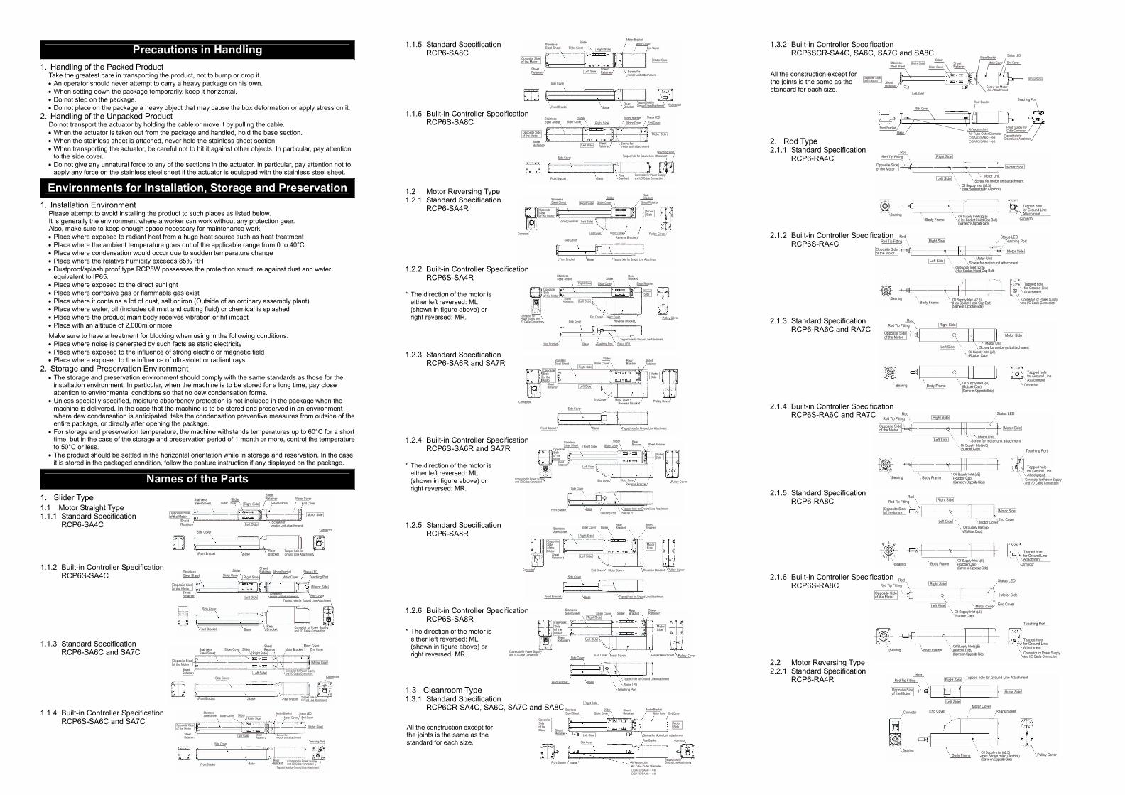
1.1.5 Standard Specification RCP6-SA8C
1.1.6 Built-in Controller Specification RCP6S-SA8C
1.2 Motor Reversing Type 1.2.1 Standard Specification
RCP6-SA4R
1.2.2 Built-in Controller Specification RCP6S-SA4R
1.2.3 Standard Specification RCP6-SA6R and SA7R
1.2.4 Built-in Controller Specification RCP6S-SA6R and SA7R
1.2.5 Standard Specification
RCP6-SA8R
1.2.6 Built-in Controller Specification RCP6S-SA8R
1.3 Cleanroom Type 1.3.1 Standard Specification
RCP6CR-SA4C, SA6C, SA7C and SA8C
1.3.2 Built-in Controller Specification RCP6SCR-SA4C, SA6C, SA7C and SA8C
2. Rod Type 2.1.1 Standard Specification
RCP6-RA4C
2.1.2 Built-in Controller Specification RCP6S-RA4C
2.1.3 Standard Specification RCP6-RA6C and RA7C
2.1.4 Built-in Controller Specification RCP6S-RA6C and RA7C
2.1.5 Standard Specification RCP6-RA8C
2.1.6 Built-in Controller Specification
RCP6S-RA8C
2.2 Motor Reversing Type 2.2.1 Standard Specification
RCP6-RA4R
* The direction of the motor is either left reversed: ML (shown in figure above) or right reversed: MR.
* The direction of the motor is either left reversed: ML (shown in figure above) or right reversed: MR.
* The direction of the motor is either left reversed: ML (shown in figure above) or right reversed: MR.
Stainless Steel Sheet
Slider Cover Slider
Sheet Retainer
Side Cover
Front Bracket Base Rear Bracket Tapped hole for Ground Line Attachment
Connector
End CoverMotor CoverSheet
Retainer Motor Bracket
Connector for Power Supplyand I/O Cable Connection
Opposite Sideof the Motor Motor Side
Right Side
Left Side
Stainless Steel Sheet Slider Cover
Slider
Sheet Retainer
Side Cover
Front Bracket BaseRear Bracket
Tapped hole for Ground Line Attachment Connector
End CoverMotor Cover
Sheet Retainer
Motor Bracket
Screw for motor unit attachment
Opposite Sideof the Motor Motor Side
Right Side
Left Side
Stainless Steel Sheet Slider Cover
Slider
Sheet Retainer
Side Cover
Front Bracket Base
Rear Bracket
Tapped hole for Ground Line Attachment
Pulley CoverEnd Cover Motor CoverReverse BracketConnector
Sheet Retainer
Opposite Sideof the Motor
Motor Side
Right Side
Left Side
Rod Tip FittingRod
Body FrameOil Supply Inlet (φ5)(Rubber Cap)(Same on Opposite Side)
Motor Cover
Tapped hole for Ground Line Attachment
End Cover
Connector
Oil Supply Inlet (φ5)(Rubber Cap)
Bearing
Opposite Sideof the Motor Motor Side
Right Side
Left Side
Rod Tip FittingRod
Body FrameOil Supply Inlet (φ2.5)(Hex Socket Head Cap Bolt)(Same on Opposite Side)
End Cover
Tapped hole for Ground Line Attachment
Motor CoverConnector
Bearing
Rear Bracket
Pulley Cover
Opposite Sideof the Motor Motor Side
Right Side
Left Side
All the construction except for the joints is the same as the standard for each size.
All the construction except for the joints is the same as the standard for each size.
Status LED
Teaching Port
Stainless Steel Sheet Slider Cover
Slider
Sheet Retainer
Sheet Retainer
Side Cover
Front BracketBase
Air Vacuum JointAir Tube Outer Diameter
Rear Bracket
Screw for MotorUnit Attachment
Tapped hole forGround Line Attachment
End CoverMotor CoverMotor Bracket
Right Side
Left Side
Opposite Sideof the Motor
Motor Side

Status LED
Teaching Port
Connector for Power Supply and I/O Cable Connection
Rod Tip Fitting
Frame Cover
Bearing
Front Bracket Base
Rear Bracket
Tapped hole for Ground Line Attachment
End Cover Motor Cover
Rod
Reverse Bracket
Hole Cap(Oil Supply Inlet)
Pulley Cover
Opposite Sideof the Motor
Motor Side
Right Side
Left Side
Rod Tip Fitting
Frame Cover
Bearing
Front Bracket Base
Rear Bracket
Tapped hole for Ground Line Attachment
Connector End Cover Motor Cover
Rod
Reverse Bracket Pulley Cover
Hole Cap(Oil Supply Inlet)
Opposite Sideof the Motor
Motor Side
Right Side
Left Side
Status LED
Teaching Port
Connector for Power Supply and I/O Cable Connection
Rod Tip Fitting
Frame Cover
Bearing
Front Bracket Base
Rear Bracket
Tapped hole for Ground Line Attachment
End Cover Motor Cover
Rod
Reverse Bracket
Hole Cap(Oil Supply Inlet)
Pulley Cover
Opposite Sideof the Motor
Motor Side
Right Side
Left Side
Front Plate
Front Cover Base Frame
Table Ball Screw Cover
Connector
Front Plate Hole Cap Motor Unit
Front Plate
Front Cover Base Frame
Table Ball Screw Cover
Connector
Front Plate Hole Cap Motor Unit (Controller Integrated Type)
Teaching Port
Front Plate
Front Cover Base Frame
Table
Ball Screw Cover
Connector
Front Plate
Reverse BracketMotor Cover
Connector Pulley CoverEnd Cover
Hole Cap
End Cover
Front Plate
Front Cover Base Frame
Table
Ball Screw Cover
Connector
Front Plate
Reverse Bracket
Motor Cover
Connector Pulley CoverReverse Bracket
Hole Cap
End CoverTeaching Port
Sheet Retainer
Oil SupplyInlet
Stainless Steel Sheet Slider Slider Cover
Front Bracket Base
Rear Bracket
Motor End Cover
Motor Bracket Motor Cover Connector
Status LED
Teaching Port
Opposite Sideof the Motor Motor Side
Right Side
Left Side
Pulley Cover
Reverse Bracket
Motor CoverMotor End Cover
Opposite Sideof the Motor Motor Side
Right Side
Left Side
Status LED
Connector for Power Supply and I/O Cable Connection
Teaching PortRod Tip Fitting
Rod
Body FrameOil Supply Inlet (φ2.5)(Hex Socket Head Cap Bolt)(Same on Opposite Side)
End Cover
Tapped hole for Ground Line Attachment
Motor Cover
Bearing
Rear Bracket
Pulley Cover
Opposite Sideof the Motor Motor Side
Right Side
Left Side
Status LED
Connector for Power Supply and I/O Cable Connection
Teaching Port
Rod Tip FittingRod
Body FrameOil Supply Inlet (φ5)(Hex Socket Head Cap Bolt)(Same on Opposite Side)
End Cover
Tapped hole for Ground Line Attachment
Motor Cover
Bearing
Rear Bracket
Pulley Cover
Opposite Sideof the Motor Motor Side
Right Side
Left Side
Rod Tip FittingRod
Body FrameOil Supply Inlet (φ5)(Hex Socket Head Cap Bolt)(Same on Opposite Side)
End Cover
Tapped hole for Ground Line Attachment
Motor CoverConnector
Bearing
Rear Bracket
Pulley Cover
Opposite Sideof the Motor Motor Side
Right Side
Left Side
Status LEDConnector for Power Supply and I/O Cable Connection
Teaching Port
Rod Tip FittingRod
Body FrameOil Supply Inlet (φ5)(Hex Socket Head Cap Bolt)(Same on Opposite Side)
End Cover
Tapped hole for Ground Line Attachment
Motor Cover
Bearing
Rear Bracket
Pulley Cover
Opposite Sideof the Motor Motor Side
Right Side
Left Side
Rod Tip Fitting
Frame Cover
Bearing Front Bracket Base Rear BracketTapped hole for Ground Line Attachment
Connector
End CoverMotor CoverRodMotor Bracket
Screw for motor unit attachment
Hole Cap(Oil Supply Inlet)
Opposite Sideof the Motor Motor Side
Right Side
Left Side
Rod Tip Fitting
Frame Cover
BearingFront Bracket Base
Rear Bracket
Tapped hole for Ground Line Attachment
Connector
End CoverMotor CoverRodHole Cap(Oil Supply Inlet)
Opposite Sideof the Motor Motor Side
Right Side
Left Side
Status LED
Teaching Port
Connector for Power Supplyand I/O Cable Connection
Rod Tip Fitting
Frame Cover
Bearing Front Bracket Base
Rear Bracket
Tapped hole for Ground Line AttachmentEnd CoverMotor Cover
RodHole Cap(Oil Supply Inlet)
Opposite Sideof the Motor Motor Side
Right Side
Left Side
Rod Tip Fitting
Frame Cover
Bearing
Front Bracket Base
Rear Bracket
Tapped hole for Ground Line Attachment
Connector
End Cover Motor Cover
Rod
Reverse Bracket Pulley Cover
Hole Cap(Oil Supply Inlet)
Opposite Side of the Motor
Motor Side
Right Side
Left Side
Rod Tip Fitting
Frame Cover
Bearing
Front Bracket Base
Rear Bracket
Tapped hole for Ground Line Attachment
Connector End Cover Motor Cover
Rod
Reverse Bracket Pulley Cover
Hole Cap(Oil Supply Inlet)
Opposite Sideof the Motor
Motor Side
Right Side
Left Side
Status LED
Teaching Port
Connector for Power Supplyand I/O Cable Connection
Rod Tip Fitting
Frame Cover
BearingFront Bracket Base
Rear Bracket
Tapped hole for Ground Line Attachment
End CoverMotor Cover
Rod
Motor Bracket
Hole Cap(Oil Supply Inlet)
Opposite Sideof the Motor Motor Side
Right Side
Left Side
2.2.2 Built-in Controller Specification RCP6S-RA4R
2.2.3 Standard Specification RCP6-RA6R and RA7R
2.2.4 Built-in Controller Specification RCP6S-RA6R and RA7R
2.2.5 Standard Specification RCP6-RA8R
2.2.6 Built-in Controller Specification RCP6S-RA8R
3. Radial Cylinder 3.1 Motor Straight Type 3.1.1 Standard Specification
RCP6-RRA4C
3.1.2 Built-in Controller Specification
RCP6S-RRA4C
3.1.3 Standard Specification RCP6-RRA6C and RRA7C
3.1.4 Built-in Controller Specification RCP6S-RRA6C and RRA7C
3.1.5 Standard Specification RCP6-RRA8C
3.1.6 Built-in Controller Specification RCP6S-RRA8C
3.2 Motor Reversing Type 3.2.1 Standard Specification
RCP6-RRA4R
3.2.2 Built-in Controller Specification RCP6S-RRA4R
3.2.3 Standard Specification
RCP6-RRA6R and RRA7R 3.2.4 Built-in Controller Specification RCP6S-RRA6R and RRA7R
3.2.5 Standard Specification RCP6-RRA8R
3.2.6 Built-in Controller Specification RCP6S-RRA8R
4. Table Type 4.1 Motor Straight Type 4.1.1 Standard Specification
RCP6-TA4C, TA6C and TA7C
4.1.2 Built-in Controller Specification RCP6S-TA4C, TA6C and TA7C
4.2 Motor Reversing Type 4.2.1 Standard Specification
RCP6-TA4R, TA6R and TA7R
4.2.2 Built-in Controller Specification RCP6S-TA4R, TA6R and TA7R
5. Wide Slider Type 5.1 Motor Straight Type 5.1.1 Standard Specification
RCP6-WSA10C, WSA12C, WSA14C and WSA16C
5.1.2 Built-in Controller Specification RCP6S-WSA10C, WSA12C, WSA14C and WSA16C
5.2 Motor Reversing Type 5.2.1 Standard Specification
RCP6-WSA10R, WSA12R, WSA14R and WSA16R
* The direction of the motor is either left reversed: ML (shown in figure above) or right reversed: MR.
* The direction of the motor is either left reversed: ML (shown in figure above) or right reversed: MR.
* The direction of the motor is either left reversed: ML (shown in figure above) or right reversed: MR.
* The direction of the motor is either left reversed: ML (shown in figure above) or right reversed: MR.
Stainless Steel Sheet
Sheet Retainer
Slider Slider Cover
Front Bracket Base
Oil SupplyInletRear Bracket End Cover
Motor Bracket
Motor Cover Connector
Opposite Sideof the Motor Motor Side
Right Side
Left Side
Rod Tip FittingRod
Body FrameOil Supply Inlet (φ5)(Hex Socket Head Cap Bolt)(Same on Opposite Side)
End Cover
Tapped hole for Ground Line Attachment
Motor CoverConnector
Bearing
Rear Bracket
Pulley Cover
Opposite Sideof the Motor Motor Side
Right Side
Left Side
* The direction of the motor is either left reversed: ML (shown in figure above) or right reversed: MR.
Rod Tip Fitting
Frame Cover
Bearing Front Bracket Base Rear Bracket
Tapped hole for Ground Line Attachment
Connector
Motor CoverMotor CoverRod
Motor Bracket
Screw for motor unit attachment
Hole Cap(Oil Supply Inlet)
Opposite Sideof the Motor Motor Side
Right Side
Left Side
Status LED
Teaching Port
Connector for Power Supply and I/O Cable Connection
Rod Tip Fitting
Frame Cover
Bearing
Front Bracket Base
Rear Bracket
Tapped hole for Ground Line Attachment
End Cover Motor Cover
Rod
Reverse Bracket
Hole Cap(Oil Supply Inlet)
Pulley Cover
Opposite Sideof the Motor
Motor Side
Right Side
Left Side
Rod Tip Fitting
Frame Cover
Bearing Front Bracket Base Rear Bracket
Tapped hole for Ground Line Attachment
Connector
Motor CoverMotor CoverRod
Motor Bracket
Screw for motor unit attachment
Hole Cap(Oil Supply Inlet)
Opposite Sideof the Motor Motor Side
Right Side
Left Side

Pulley Cover
Reverse Bracket
Motor CoverMotor End Cover
Opposite Sideof the Motor Motor Side
Right Side
Left Side
Connector
Stainless Steel Sheet Slider CoverSlider
SheetRetainer
Supply Inlet
Front Bracket Base
Air Vacuum JointAir Tube Outer Diameter
Rear Bracket Motor End Cover
Motor CoverMotor Bracket
Right Side
Left Side
Opposite Sideof the Motor
Motor Side
Connector
Stainless Steel Sheet Slider CoverSlider
SheetRetainer
Supply Inlet
Front Bracket Base
Air Vacuum JointAir Tube Outer Diameter
Rear BracketMotor End Cover
Motor Cover
Status LED
Teaching PortMotor Bracket
Right Side
Left Side
Opposite Sideof the Motor
Motor Side
5.2.2 Built-in Controller Specification RCP6S-WSA10R, WSA12R, WSA14R and WSA16R
5.3 Cleanroom Type 5.3.1 Standard Specification
RCP6CR-WSA10C, WSA12C, WSA14C and WSA16C 5.3.2 Built-in Controller Specification
RCP6SCR- WSA10C, WSA12C, WSA14C and WSA16C 6. Wide Radial Cylinder 6.1 Motor Straight Type 6.1.1 Standard Specification
RCP6-WRA10C, WRA12C, WRA14C and WRA16C
6.1.2 Built-in Controller Specification RCP6S-WRA10C, WRA12C, WRA14C and WRA16C
6.2 Motor Reversing Type 6.2.1 Standard Specification
RCP6-WRA10R, WRA12R, WRA14R and WRA16R
6.2.2 Built-in Controller Specification RCP6S-WRA10R, WRA12R, WRA14R and WRA16R
Attachment Refer to the Instruction Manual (DVD) for the attachments of the actuator and loads. [Precautions for Attachments]
No. Item Precautions 1 Installation • Installing the slider type and wide slider type in the horizontally oriented wall
mount or ceiling mount may cause the stainless steel sheet to be loosened or be off the right position. Continued use of the actuator with this condition may result in the breakage of the stainless steel sheet. Adjust the sheet tension accordingly in the regular inspection. (Refer to the maintenance section on the Instruction Manual for the procedure of stainless steel sheet tension adjustment.)
• Avoid using the actuator with no brake in the vertical orientation.
No. Item Precautions 2 Attachment Surface • The base has to have a structure with sufficient rigidity to prevent oscillation.
• The side and the bottom surfaces of the base of the actuator are the reference for the slider drive. If accuracy for its run is required, use these surfaces as a reference of the installation.
• The actuator mounting surface and other surfaces that are used as a reference
should be flat enough with an accuracy of machining or equivalent treatment, and the flatness of the mounting surface needs to be 0.05mm/m or less.
• Secure the space where maintenance work can be performed.
3 Bolt to be used • For the bolts to be used, a high-tensile bolt complying with ISO-10.9 or more is recommended.
• If using the tapped holes, use screws with the thread length dimension being less than the effective depth of the holes.
• In case the tapped hole is a through hole, be careful so the screw tip does not exceed the surface of the tapped hole.
• For the actuator mounting, use a bolt with the dimension of its effective mating length to the tapped hole is as stated below. If tapped hole on steel → thread length same as nominal diameter If tapped hole on aluminum → thread length 1.8 times longer than nominal diameter However, there are some models specifying the effective length of thread engagement. Refer to the instruction manual (DVD).
4 Tightening Torque • Please follow the specification values stated in the Instruction Manual (DVD) for the tightening torque. Failure to do so may cause an operation problem.
5 Load Moment and Overhung length
• Please follow the specification values stated in the Instruction Manual (DVD) for the load moment and the overhung length of the slider type, table type and wide slider type. Failure to do so may cause abnormal vibration or noise, and also may remarkably shorten the product life.
6 Rod Tip Allowable Static Load, Load Offset Distance
• Follow the specific values described in the instruction manual (DVD) for the rod tip dynamic allowable load and the load offset distance for the rod type, radial cylinder and wide radial cylinder. Failure to do so may cause abnormal vibration or noise, and also may remarkably shorten the product life.
7 Stainless steel sheet • Do not attempt to hold the stainless steel sheet directly with hand on slider type and wide slider type. Please, also, be careful not to make a dent on the stainless steel sheet. Stainless sheet is easy to get dented because it is thin. Using it with a dent on may cause a breakage.
• If there is dust or metal contamination attached on the stainless steel sheet, please wipe it off the sheet surface. Operation with the stainless sheet that has foreign matters on its surface may cause problems such as sheet damage, waviness, etc. inside the slider.
• Please do not operate the unit in the ambient with dust or metal contamination.
For the controller, only the dedicated controller manufactured by our company can be used. For the connection between the actuator of RCP6 standard specification and controller, use the attached dedicated connection cable.
r
RCP6-XX (connects controller and RCP6)
PCON-CBPCON-CFBMCONMSEL SA4, SA6, SA7, RA4, RA6, RA7, RRA4, RRA6, RRA7, TA4, TA6, TA7, WSA10, WSA12, WSA14, WRA10, WRA12 and WRA14
SA8, RA8,RRA8, WSA16 and WRA16
[Prohibited Items in the Cable Processing]
• Do not pull or bend forcibly the cable so as not to give any extra load or tension to the cable. • Do not process the cable for extension or shortening by means of cutting out, combination or
connecting with another cable. • Do not bend the cable in the area from the connector tip to 150mm on the both ends.
Standard cable : CB-CAN-MPA□□□, CB-CFA3-MPA□□□ Robot cable : CB-CAN-MPA□□□-RB, CB-CFA3-MPA□□□-RB
150mm 150mm
• Do not let the cable flex at a single point. • Do not let the cable bend, kink or twist.
• Do not pull the cable with a strong force. • Do not let the cable receive a turning force at a
single point. • Do not pinch, drop a heavy object onto or
cut the cable. • When fixing the cable, provide a moderate slack
and do not tension it too tight. • Separate the I/O line, communication line
and power line from each other. Do not store in the same duct.
Follow the instructions below when using a cable track.
• If there is an indication to the cable for the space factor in a cable track, refer to the wiring instruction given by the supplier when storing the cable in the cable track.
• Avoid the cables to get twined or twisted in the cable track, and also to have the cables move freely and do not tie them up. (Avoid tension being applied when the cables are bent.) Do not pile up cables. It may cause faster abrasion of the sheaths or cable breakage.
Note: • When the cable is connected or disconnected, make sure to turn off the power to the
controller. When the cable is connected or disconnected with the controller power turned ON, it might cause a malfunction of the actuator and result in a serious injury or damage to the machinery.
• When the connector connection is not correct, it would be dangerous because of a malfunction of the actuator. Make sure to confirm that the connector is connected correctly.
RCP6S Built-in Controller Type Actuator Installation and Wiring
Refer also to the first step guide for RCP6S Gateway Unit if connection is to be established with the gateway.
Installation and Noise Elimination 1. Noise Elimination Grounding (Frame Ground)
2. Precautions regarding wiring method 1) Wire is to be twisted for the 24V DC power supply. 2) Separate the signal and encoder lines from the power supply and
power lines.
3. Noise Sources and Elimination Carry out noise elimination measures for electrical devices on the same power path and in the same equipment. The following are examples of measures to eliminate noise sources. 1) AC solenoid valves, magnet switches and relays
[Measure] Install a Surge absorber parallel with the coil. 2) DC solenoid valves, magnet switches and relays
[Measure] Mount the windings and diodes in parallel. Select a diode built-in type for the DC relay.
Steel Strap(Piano Wire)
Tie them up softly.
Do not use spiral tube in any position where cables are bent frequently.
Power LineDuct
I/O Line(Flat Cable, etc.)
Wiring
Ground Terminal Grounding resistance at 100Ω or less.
Copper wire: Connect a ground wire with a diameter of 1.6 mm (2mm2: AWG 14) or larger.
Connect the ground line to the FG terminal on the PLC connection unit power supply connector connected to RCP6S.
PLC Connection Unit
* The direction of the motor is either left reversed: ML (shown in figure above) or right reversed: MR.
* The direction of the motor is either left reversed: ML (shown in figure above) or right reversed: MR.
Reference Surfaces
Reference Surfaces
Frame CoverOil Supply Inlet
Tip Fitting Base
Rear Bracket Motor End Cover
Motor BracketMotor Cover Connector
Rod
Opposite Sideof the Motor Motor Side
Right Side
Left Side
Status LED
Teaching Port
Frame CoverOil Supply Inlet
Tip Fitting Base
Rear Bracket
Motor End Cover
Motor BracketMotor Cover Connector
Rod
Opposite Sideof the Motor Motor Side
Right Side
Left Side
Pulley Cover
Reverse Bracket
Motor CoverMotor End Cover
Opposite Sideof the Motor Motor Side
Right Side
Left Side
Pulley Cover
Reverse Bracket
Motor CoverMotor End Cover
Opposite Sideof the Motor Motor Side
Right Side
Left Side
PLC Unit
PLC Unit
Other equipment Other equipment
Other equipmentOther equipment
Do not share the ground wire with or connect to other equipment. ground each unit.
* The direction of the motor is either left reversed: ML (shown in figure above) or right reversed: MR.
All the construction except for the joints is the same as the standard for each size.
All the construction except for the joints is the same as the standard for each size.
Surge absorber
Relay
Relay coil

PLC Unit
Axis Power Supply Connector
RCP6S Actuator
Power Supply Connector
Motor Power Supply
Brake Release Power(Note) When a brake-equipped actuator is connected
FG
DC24VPower Supply
24V0V
S1
S2
MP
24V0V
EMG-
BK
External Emergency Stop Switch
RCP6S Actuator(Max. 16 units)
Use a hub unit if necessaryOne hub unit is available for four units of RCP6S actuator to be connected at the maximum.
Connect RCP6S actuator to the axes control connector (C) when a hub unit is not to be used.
RCP6SGateway Unit Emergency Stop Switch
on the Teaching Pendant
SIO ConnectorSystem I/OConnector
Emergency Stop Switch
Emargency Stop Reset
Switch
Axis Power Supply Connector
Hub Unit 1
Hub Unit 2
Hub Unit 3
Hub Unit 4
Axis ControlConnector
Control Power Supply
Motor Power Supply Connector
Control Power Supply Connector
Emergency Stop Detection Circuit
Drive Cutoff/Emergency stop Input Connector(Note 2)
(Note 2)
(Note 2)
(Note 2)
(Note 2)
(Note 4)
(Note 1)
(Note 3)
Wiring Diagram 1. When Controlled with Fieldbus
2. When Controlled with Serial Communication
Note: Turn off the power to the gateway unit and RCP6S built-in controller before plugging in and out the connectors
on the PC software or a teaching pendant to the gateway unit or RCP6S built-in controller. Inserting or removing the connector while the power is turned ON causes a gateway unit failure.
Power Supply and Emergency Stop Circuit It is an example for a wire layout in order to shut the motor power supply externally at the emergency stop input. 1. Noise Elimination Grounding (Frame Ground)
Note 1 RCM-P6GW: When there is nothing plugged in the SIO connector, S1 and S2 are short-circuited inside the controller. RCM-P6GWG: When there is nothing plugged in the SIO connector, S1 and S2 are not short-circuited.
To make them short-circuited, have the enclosed dummy plug DP-5 plugged in the SIO connector. Note 2 When the motor power must be disconnected externally for safety category compliance, apply a safety rated relay
between MPI-AXIS□ and MPO-AXIS□. Note 3 The rating for the emergency stop signal (EMG-) to turn ON/OFF at contact CR1 is 24V DC and 10mA or less. Note 4 For CR1, select the one with coil current 0.1A or less.
2. When Controlled with Serial Communication
Note: When supplying power by turning on/off 24V DC, keep 0V connected and have +24V supplied and shut (shut on one side). The rating for the emergency stop signal (EMG-) is 24V DC and 10mA or less. Have an interval of 1sec or more after shutting the power off before turning it back on. Do not attempt to supply only motor power while the control power is not supplied.
Head Office: 577-1 Obane Shimizu-KU Shizuoka City Shizuoka 424-0103, JapanTEL +81-54-364-5105 FAX +81-54-364-2589
website: www.iai-robot.co.jp/
Ober der Röth 4, D-65824 Schwalbach am Taunus, GermanyTEL 06196-88950 FAX 06196-889524
SHANGHAI JIAHUA BUSINESS CENTER A8-303, 808, Hongqiao Rd. Shanghai 200030, ChinaTEL 021-6448-4753 FAX 021-6448-3992
website: www.iai-robot.com
Technical Support available in USA, Europe and China
Head Office: 2690 W. 237th Street, Torrance, CA 90505TEL (310) 891-6015 FAX (310) 891-0815
Chicago Office: 110 East State Parkway, Schaumburg, IL 60173TEL(847) 908-1400 FAX (847) 908-1399
TEL (678) 354-9470 FAX (678) 354-9471website: www.intelligentactuator.com
Atlanta Office: 1220 Kennestone Circle, Suite 108, Marietta, GA 30066
825 PhairojKijja Tower 12th Floor, Bangna-Trad RD., Bangna, Bangna, Bangkok 10260, ThailandTEL +66-2-361-4458 FAX +66-2-361-4456
Manual No.: ME3755-3A
Hub Unit (Max. 4 units)
Gateway Unit
Control/Drive Power Supply (DC24V•••Please prepare separately)
Drive Cutoff Circuit
Emergency Stop Circuit
Host System (master unit•••Please prepare separately)
PC Software (to be purchased separately)
Teaching Pendant (to be purchased separately)
Fieldbus Connecting
Dummy Plug DP-5 (Note 1)
It is also available to connecting with miniUSB.
Note 1: For RCM-P6GWG, insert the enclosed dummy plug (DP-5) to the SIO connector unless a teaching tool is connected to it.
RCP6S Actuator
Serial Communication
PLC Connection Unit
RCP6S Actuator
(Max. 16 units)
CB-RCP6S-PWBIO□□□ (Enclosed to actuator)
CB-RCP6S -RLY□□□
(Prepare separately)
Axis Connector
Power Supply Connector
PLC Connector
SIO Connector
Drive Cutoff Connector
Control Power Supply Connector Motor Power Supply Connector
RCP6S Connector
Hub Control Connector
Hub Power Supply Connector
Axis Power Supply Connector Axis Control Connector (Bottom)
System I/O Connector (Top)
CB-RCP6S -PWBIO□□□
(Enclosed to actuator)
Teaching Pendant (to be purchased separately)
PC Software (to be purchased separately)
Host System (master unit•••Please prepare separately)
Control/Drive Power Supply (DC24V•••Please prepare separately)