Embed Size (px)
Citation preview

belfuse.com/power-solutions
BCD.00791 Rev AF, 12-Jun-2018
RCM150/300 Series 150/300 W DC-DC Converters
The RCM Series converters are reliable power supplies for railway and transportation systems. There are 2 input voltage ranges covering all common railway batteries. The output delivers 150 or 300 W at 12, 15 or 24 V. The converters are designed for chassis mounting and exhibit a closed housing with cooling openings.
Many options are available, such as an output ORing FET for redundant operation, output voltage adjustment, interruption time of 10 ms (class ST2), shutdown input, and an output voltage monitor controlling a relay (change-over contact).
Features• RoHS lead-free-solder product• 2 input voltage ranges, covering all railway batteries• Single output 12, 15 or 24 V• Closed housing for chassis mounting• Extremely high efficiency and high power density• Low inrush current• 3 connectors: Input, output, auxiliary• Overtemperature, overvoltage, overcurrent, and overload
protection• Many options available• Compliant to EN 50155, EN 50121-3-2, AREMA• Fire and smoke: compliant to EN 45545 and NFPA 130• 5 year warranty
Safety-approved to the latest edition of IEC/EN 60950-1and UL/CSA 60950-1
Table of Contents Description........................................................................................1Model Selection ................................................................................2Functional Description ......................................................................3Electrical Input Data .........................................................................4Electrical Output Data.......................................................................7Description of Options ....................................................................10
Electromagnetic Compatibility (EMC) .............................................12Immunity to Environmental Conditions ...........................................14Mechanical Data .............................................................................15Safety and Installation Instructions .................................................16Accessories ....................................................................................18
1
1 pending
1

[email protected] belfuse.com/power-solutions
BCD.00791 Rev AF, 12-Jun-2018
Page 2 of 18
RCM Series 150 / 300 W DC-DC Converters
© 2018 Bel Power Solutions & Protection
Model SelectionTable 1: Standard models
Input voltage Output Power Efficiency 2 Model Options
Vi min1
[V]Vi cont
[V]Vi max
1
[V]Vo nom
[V]Io nom
[A]Po nom
[W]η min η typ
[%]
14.4 16.8 (24) 45 50.4
12 12.5 150 88 90 24RCM150-12
D, M, Q, F, K
15 10.0 150 24RCM150-15
24 6.25 150 90 91 24RCM150-24
43.2 50.4 (110) 137.5 154
12 12.5 150 91 92.5 110RCM150-12
15 10.0 150 110RCM150-15
24 6.25 150 92 93 110RCM150-24
14.4 16.8 (24) 45 50.412 25 300 89 90.5 24RCM300-12
24 12.5 300 90 91 24RCM300-24
43.2 50.4 (110) 137.5 15412 25 300 91 92.5 110RCM300-12
24 12.5 300 92 93.5 110RCM300-241 Short time; see table 2 for details.2 Efficiency at TA = 25 °C, Vi nom, Io nom, Vo nom, only option D fitted.
Part Number Description
Operating input voltage Vi cont (continuously): 16.8 – 45 VDC ...........................................................24 50.4 – 137.5 VDC ..................................................... 110
Series .............................................................................RCM
Output power: 150 W .....................................................................150 300 W .....................................................................300
Nominal output voltage: 12 V ...........................................................................-12 15 V ...........................................................................-15 24 V ...........................................................................-24Auxiliary functions and options: Out OK, output voltage adjust, shutdown 1 .................. D Interruption time ...........................................................M ORing FET....................................................................Q Fuse built-in ...................................................................F Pluggable Connectors ................................................. K
1 Opt. D requires the auxiliary connector.
Note: The sequence of options must follow the order above.
Note: All models are RoHS-compliant for all six substances.
110 RCM 150 -24 D M Q F K
Available combinations of options:24/110RCMxxx-xx (K)24/110RCMxxx-xxD (K)24/110RCMxxx-xxDF (K)24/110RCMxxx-xxDMQ (K)24/110RCMxxx-xxDMQF (K)
Example: 110RCM150-24DMQ: DC-DC converter, input voltage range 50.4 to 137.5 V continuously, output providing 24 V /6.25 A, monitoring relay, output voltage adjust, shutdown input, interruption time 10 ms, integrated ORing FET, operating ambient temperature TA = –40 to 70 °C, RoHS-compliant for all six sub stances.

[email protected] belfuse.com/power-solutions
BCD.00791 Rev AF, 12-Jun-2018
Page 3 of 18
RCM Series 150 / 300 W DC-DC Converters
© 2018 Bel Power Solutions & Protection
Product MarkingType designation, applicable safety approval and recognition marks, CE mark, pin allocation, and product logo.Input voltage range and input current, nominal output voltage and current, degree of protection, batch no., serial no., and data code including production site, version (modification status) and date of production.
Functional DescriptionThe converters are designed as active clamp forward con verters with a switching frequency of approximately 120 kHz. The built-in high-efficient input filter together with a small input capacitance generates very low inrush current of short duration. An antiparallel diode acts as reverse polarity pro tection together with the external circuit breaker or fuse.The circuitry providing the interruption time (opt. M) is located after the input filter.The rectification on the secondary side is provided by syn chronous rectifiers, in order to keep the losses as low as possible. The output voltage control logic is located on the secondary side and influences the primary logic through magnetic feedback.An auxiliary converter supplies all circuits with a stable bias voltage. An output ORing FET is available (option Q) and allows for a redundant power supply system. If there are no external circuit breakers, it is possible to order the converter with incor porated fuse (opt. F). Because this fuse is not accessible, a serial diode provides reverse polarity protection (only with option F or M).Opt. D encompasses an additional auxiliary connector and allows for output voltage adjust and a primary shutdown. An output voltage monitor controls a relay with a change-over contact.
Vi–
Vi+
Isol
atio
n
Vo–
JM194f
Auxiliary connector (only with option D)
Vo+
Auxiliaryconverter
Cy
SD0SD
CyCy PE
Opt. Q
Fuse(option F)
OK0
+Chu
Opt. M
Inputfilter
Primarycontrol logic
NTC
1 Series diode, only fitted with opt. F or M
1
Outputfilter
OK2Secondarycontrol logic
R– R R R+
Isolateddriver
NTC
OK1
2
2 Bipolar suppressor diode with opt. F or M
Fig. 1Block diagram

[email protected] belfuse.com/power-solutions
BCD.00791 Rev AF, 12-Jun-2018
Page 4 of 18
RCM Series 150 / 300 W DC-DC Converters
© 2018 Bel Power Solutions & Protection
Electrical Input DataGeneral conditions:
- TA = 25 °C, unless TC is specified.
Table 2a: Input data of RCM150 models
Model 24RCM150 110RCM150 Unit
Characteristics Conditions min typ max min typ max
Vi cont Operating input voltage continuous Io = 0 – Io maxTC min – TC max
16.8 (24) 45.0 50.4 (110) 137.5
VVi 2s for ≤ 2 s without shutdown 14.4 50.4 43.2 154
Vi nom Nominal input voltage 24, (36) (72), (96), 110
Vi abs Input voltage limits 3 s without damage 0 55 0 165
Ii Typical input current Vi nom, Io nom 6.8 1.5 A
P i 0 No-load input power Vi min – Vi max, Io = 0 2.5 4 4 2 6W
P i SD Idle input power Vi min – Vi max, VSD = 0 V 0.7 1.5 0.7 2 1.5
Ci Input capacitance 1 40 10 µF
Ri Input resistance 100 100 mΩ
Iinr p Peak inrush currentVi = Vi max, Po nom
75 100 A
tinr d Duration of inrush current 0.5 0.5
mston Start-up time after removal of shutdown
Vi min, Po nom 1000 1000
0 → Vi min, Po nom
VSD = 0 → 5 V300 300
Table 2b: Input data of RCM300 models
Model 24RCM300 110RCM300 Unit
Characteristics Conditions min typ max min typ max
Vi cont Operating input voltage continuous Io = 0 – Io maxTC min – TC max
16.8 (24) 45.0 50.4 (110) 137.5
VVi 2s for ≤ 2 s without shutdown 14.4 50.4 43.2 154
Vi nom Nominal input voltage 24, (36) (72), (96), 110
Vi abs Input voltage limits 3 s without damage 0 55 0 165
Ii Typical input current Vi nom, Io nom 13.9 3 A
P i 0 No-load input power Vi min – Vi max, Io = 0 4 6 4 6W
P i SD Idle input power Vi min – Vi max, VSD = 0 V 1.5 1.5
Ci Input capacitance 1 6 12 µF
Ri Input resistance 140 140 mΩ
Iinr p Peak inrush currentVi = Vi max, Po nom
120 150 A
tinr d Duration of inrush current 0.5 0.5
mston Start-up time after removal of shutdown
Vi min, Po nom 1000 1000
0 → Vi min, Po nom
VSD = 0 → 5 V300 300
1 Not smoothed by the inrush current limiter at start-up (for inrush current calculation)2 Typ. value at Vi max. At lower Vi, the idle and low-load input power are smaller.

[email protected] belfuse.com/power-solutions
BCD.00791 Rev AF, 12-Jun-2018
Page 5 of 18
RCM Series 150 / 300 W DC-DC Converters
© 2018 Bel Power Solutions & Protection
Input Transient and Reverse Polarity Protection A suppressor diode and a symmetrical input filter form an effective protection against input transients, which typically occur in many installations, but especially in battery-driven mobile applications. If the input voltage has the wrong polarity, the incorporated antiparallel diode causes the external input circuit breaker or fuse to trip. With option M or F (incorporated fuse), an active reverse-polarity protection circuit prevents from any damage.
Input Under- /Overvoltage LockoutIf the input voltage is out of range, an internally generated inhibit signal dis ables the converter to avoid any damage.
Inrush Current and Stability with Long Supply LinesThe converter operates with relatively small input capacitance C i resulting in low inrush current of short duration. If a converter is connected to the power source through supply lines with reasonable length, no additional measures are necessary to ensure stable operation.Only in the case of very long supply lines exhibiting a con siderable inductance Lext, an additional external capacitor Cext connected across the input pins improves the stability and prevents oscillations; see fig. 2.
Vi+
Vi–
Vo+
Vo–
+
Lext Rext
JM085d
Cext
LoadCi ri
ConverterRi
Table 3: Recommended values for the capacitor Cext
VB nom RCM150 RCM300 Rated voltage
24 V 1500 μF 3000 μF 40 V
36 V 1000 μF 2000 μF 63 V
72 V 220 μF 440 μF 125 V
110 V 100 μF 200 μF 200 V
Fig. 2Input configuration
Actually, the RCM Series converter with its load acts as negative resistor r i, because the input current I i rises, when the input voltage Vi is decreased. It tends to oscillate with a resonant fre quency determined by the line inductance Lex t and the input capacitance Ci + Cext, damped by the resistor Rext. The whole system is not linear at all and eludes a simple calculation. One basic condition is given by the formula: Lext • Po max dV i C i + Cext >
_________ (r i = ____ ) Rext • Vi min² dI i
Rext is the series resistor of the voltage source including supply lines. If this condition is not fulfilled, the converter may not reach stable operating conditions. Worst case conditions are at lowest Vi and highest output power Po.Recommended values for Cext for different batteries are listed in table 3, which should allow for stable operation up to an input inductance of 2 mH. Ci is specified in table 2.

[email protected] belfuse.com/power-solutions
BCD.00791 Rev AF, 12-Jun-2018
Page 6 of 18
RCM Series 150 / 300 W DC-DC Converters
© 2018 Bel Power Solutions & Protection
EfficiencyThe efficiency depends on the model and on the input voltage.
60
70
80
90
0.4 0.8 Po / Po nom0
JM217100
η [%]
0.60.2
Vi = 50 V Vi = 110 V
110RCM150-12DMQ
Vi = 137 V
60
70
80
90
0.4 0.8 Po / Po nom0
JM210b100
η [%]
0.60.2
Vi = 50 V Vi = 110 V
110RCM150-24DMQ
Vi = 137 V
Fig. 3aEfficiency versus Vi and Po (110RCM150-12DMQ)
Fig. 3bEfficiency versus Vi and Po (110RCM150-24DMQ)
60
70
80
90
0.4 0.8 Po / Po nom0
JM218100
η [%]
0.60.2
Vi = 50 V Vi = 110 V
110RCM300-24DMQ
Vi = 137 V
Fig. 3cFig. 3cEfficiency versus Vi and Po (110RCM300-24DMQ)

[email protected] belfuse.com/power-solutions
BCD.00791 Rev AF, 12-Jun-2018
Page 7 of 18
RCM Series 150 / 300 W DC-DC Converters
© 2018 Bel Power Solutions & Protection
Electrical Output DataGeneral conditions:
- TA = 25 °C, unless TC is specified- R input not connected
Table 4a: Output data of RCM150 models.
Output 12 V 15 V 24 V Unit
Characteristics Conditions min typ max min typ max min typ max
Vo Output voltage 1 Vi nom, 0.5 Io nom 11.88 12 12.12 23.76 24 24.24V
Vow Worst case output voltageVi min – Vi max TC min – TC max, 0 - Io nom
11.64 12.36 23.28 24.72
Vo droop Output voltage droop - 20 - 40 mV/A
Vo L Overvoltage shutdown 6 14 28V
Vo P Overvoltage protection 2 14.3 15 15.8 28.5 30 31.5
Io nom Nominal output current 12.5 6.25A
Io L Output current limit TC min – TC max 13.0 15 6.5 7.2
vo Output noise 3Switching frequency Vi nom, Io nom
BW = 20 MHz40 80
mVppTotal incl. spikes 60 120
vod Dynamic load regulation
Voltage deviation 5 Vi nom ,
0.1 ↔ 0.9 Io nom
700 1000
t d 4 Recovery time 5 5 ms
α vo Temperature coefficient of vo (NTC) 0 - Io nom, TC min – TC max - 0.02 0 - 0.02 0 %/K
Table 4b: Output data of RCM300 models.
Output 12 V 24 V Unit
Characteristics Conditions min typ max min typ max
Vo Output voltage 1 V i nom, 0.5 Io nom 11.88 12 12.12 23.76 24 24.24V
Vow Worst case output voltageVi min – Vi max TC min – TC max, 0 - Io nom
11.64 12.36 23.28 24.72
Vo droop Output voltage droop - 20 - 40 mV/A
Vo L Overvoltage shutdown 6 14 28V
Vo P Overvoltage protection 2 14.3 15 15.8 28.5 30 31.5
Io nom Nominal output current 25 12.5A
Io L Output current limit TC min – TC max 27 30 13.5 15
vo Output noise 3Switching frequency V i nom, Io nom
BW = 20MHz60 80
mVppTotal incl. spikes 80 120
vod Dynamic load regulation
Voltage deviation 5 Vi nom ,
0.1 ↔ 0.9 Io nom
1000 1200
t d 4 Recovery time 5 5 ms
α vo Temperature coefficient of vo (NTC) 0 - Io nom, TC min – TC max - 0.02 0 - 0.02 0 %/K
1 If the output voltage is increased above Vo nom through R-input control, the output power should be reduced accordingly, so that Po max and TC max are not exceeded.
2 Breakdown voltage of the incorporated suppressor diode at 1 mA . Exceeding this value might damage the suppressor diode.3 Measured according to IEC/EN 61204 with a probe described in annex A4 Recovery time until Vo returns to ±1% of Vo; see fig. 4. 5 No overshoot at switch on. 6 Output overvoltage protection by an electronic circuitry.
[email protected] belfuse.com/power-solutions
BCD.00791 Rev AF, 12-Jun-2018
Page 8 of 18
RCM Series 150 / 300 W DC-DC Converters
© 2018 Bel Power Solutions & Protection
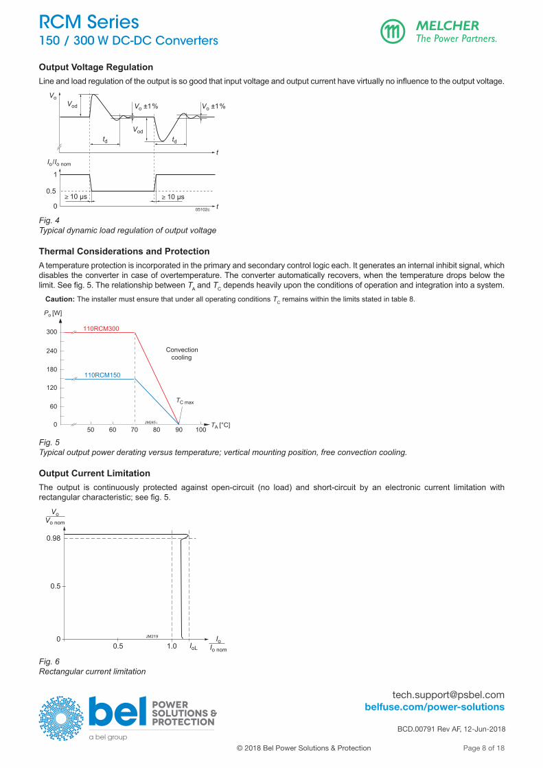
Output Voltage RegulationLine and load regulation of the output is so good that input voltage and output current have virtually no influence to the output voltage.
Vod
Vodtd td
Vo ±1% Vo ±1%
t
t ≥ 10 µs ≥ 10 µs
Vo
0
0.5
1
Io/Io nom
05102c
Fig. 4Typical dynamic load regulation of output voltage
Thermal Considerations and ProtectionA temperature protection is incorporated in the primary and secondary control logic each. It generates an internal inhibit signal, which disables the converter in case of over tem per a ture. The converter automatically recovers, when the temper a ture drops below the limit. See fig. 5. The relationship between TA and TC depends heavily upon the conditions of operation and integration into a system.
Caution: The installer must ensure that under all operating con ditions TC remains within the limits stated in table 8.
0
60
120
180
240
50 60 70 80 90 100
Po [W]
TA [°C]
300 110RCM300
JM245
TC max
Convection cooling
110RCM150
Fig. 5Typical output power derating versus temperature; vertical mounting position, free convection cooling.
Output Current LimitationThe output is continuously protected against open-circuit (no load) and short-circuit by an electronic current limitation with rectangular characteristic; see fig. 5.
VoVo nom
0.98
0.5
00.5 1.0 IoL
IoIo nom
JM219
Fig. 6Rectangular current limitation

[email protected] belfuse.com/power-solutions
BCD.00791 Rev AF, 12-Jun-2018
Page 9 of 18
RCM Series 150 / 300 W DC-DC Converters
© 2018 Bel Power Solutions & Protection
Series and Parallel ConnectionThe outputs of several RCM Series converters may be con nected in series.
Note: If the sum of the output voltages is greater than 60 V, it cannot be considered as SELV (Safety Extra Low Voltage) according to the safety standards.
Several RCM models of the same type can be operated in parallel connection. To ensures proper current sharing, the load lines should have equal length and section. The output voltage exhibits a slight droop characteristic, which facilitates current sharing. In addition, the output voltage tends to be lowered with increasing temperature.
Redundant SystemsFor redundant systems, we recommend the options Q and D, see Options.
LED IndicatorThe converters exhibit a green LED “Out OK”, signaling that the output voltage is within the specified range.

[email protected] belfuse.com/power-solutions
BCD.00791 Rev AF, 12-Jun-2018
Page 10 of 18
RCM Series 150 / 300 W DC-DC Converters
© 2018 Bel Power Solutions & Protection
Description of Options
Option D: Output Monitor, Output Adjust, ShutdownOption D consists of several auxiliary functions and en compasses an additional auxiliary connector.
Output Voltage Adjust (R)Note: With open R-input, Vo = Vo nom.
The converter allows for adjusting the output voltage in the range of 80 to 105% of Vo nom. The adjust is accomplished by an external resistor Rext1 or Rext2, connected to the R-input; see fig. 7.Depending on the value of the required output voltage, the resistor shall be connected: either: Between the R-pin and R– to adjust the output voltage to a value below Vo nom: Vo
Rext1 ≈ 4 kΩ • ––––––––– – 15.8 kΩ Vo nom – Vo
Note: Rext1 = 0 Ω reduces Vo to 80%.
or: Between the R-pin and R+ to adjust the output voltage to a value greater than Vo nom: (Vo – 2.5 V)Rext2 ≈ 4 kΩ • –––––––––– –––––––– – Ra
2.5 V • (Vo/Vo nom – 1)
Note: Rext2 = 0 Ω increases Vo to 105%.
Ra = 300 kΩ for Vo nom = 12 V Ra = xxx kΩ for Vo nom = 15 V Ra = 680 kΩ for Vo nom = 24 V
R–
R+
Vo–
4 kΩVref = 2.5 V
Rext1
Rext2
JM244
Vi–
Vi+
+Control
logic
BiasRa
15.8 kΩ
R
Fig. 7Output voltage control via R-input
Output Voltage Monitor (D)The output voltage Vo is monitored. When Vo is in range, a relay with a change-over contact is activated, connecting OK0 with OK1.
Note: The trigger levels are typ. ±5 % of Vonom (with open R-input).
Data of relay contacts: 0.4 A /150 VDC
Primary Shutdown (SD)The output of the converter may be enabled or disabled by a logic signal (e.g. CMOS) applied between the shutdown pin SD and SD0 (= Vi–). If the shutdown function is not re quired, pin SD can be left open-circuit. Voltage on pin SD:
Converter operating: 12 to 154 V or open-circuitConverter disabled: –2 to +2 V
The output response is shown in fig. 8.Note: In systems consisting of several converters, this feature may be used to control the activation sequence by logic signals or to enable the power source to start up, before full load is applied.

[email protected] belfuse.com/power-solutions
BCD.00791 Rev AF, 12-Jun-2018
Page 11 of 18
RCM Series 150 / 300 W DC-DC Converters
© 2018 Bel Power Solutions & Protection
Option M: Interruption TimeThe interruption time thu is specified in the railway standard EN 50155:2017 clause 5.1.1.4: It is tested at the nominal battery voltage for interruption and short-circuit of the input. After such an event, the system is ready for another such event after 10 s. Fig. 8 shows the output voltage Vo with option M. thu = 10 ms (Class S2) in all other cases. For less critical applications, option M is not required (class S1, no interruption time).
0
t0
SD1
0.1
1Vo/Vo nom
ton
tf
JM193a
t off
tr thu
td on
Fig. 8Typical output response to the SD-signal. If option M is not fitted, thu = 0 ms.
Option Q: ORing FET for Redundant Systems The outputs of 2 parallel connected converters are separated with ORing diodes (built by FETs). If one converter fails, the remaining one must be capable to still deliver the full power to the load. If more power is needed, the system may be extended to more parallel converters (n+1 re dundancy).Current sharing must be ensured by load lines of equal section and length. In addition, a slight droop characteristic of the output voltage and a negative temperature coefficient are helpful as well.To keep the losses as small as possible, the ORing diode is replaced by a FET. The voltage drop is approx. 22 mV (not dependent of Io).
Note: In the case of a failing converter, the output voltage is maintained by the redundant converters. However, the failing item should be identified and replaced. We recommend the Out OK function (option D).
Option F: Incorporated FuseThe railway standard EN 50155 disadvises fuses in the con verters. Consequently, the installer must preview an external fuse or circuit breaker. However, when this is not possible, an in corporated fuse is available (option F). This fuse is not accessible and will not trip, except if the converter is defect.
Note: Converters with option F or option M are protected against input reverse polarity by a series diode.
Table 5: Recommended external fuses (same as with option F)
Converter Specification Ordering number24RCM150 15 A fast acting BEL 0ADE (P) 15-R
24RCM300 25 A fast acting BEL 0ADE (P) 25-R
110RCM150 5 A fast acting Littelfuse 0507 005.MXEP
110RCM300 8 A fast acting Littelfuse 0507 008.MXEP
Option K: Pluggable ConnectorsThis option allows the use of pre-assembled pluggable connectors; for details see Accessories.
Note: Female connectors must be ordered separately.

[email protected] belfuse.com/power-solutions
BCD.00791 Rev AF, 12-Jun-2018
Page 12 of 18
RCM Series 150 / 300 W DC-DC Converters
© 2018 Bel Power Solutions & Protection
Electromagnetic Compatibility (EMC)
Electromagnetic Immunity
Table 6: Electromagnetic immunity (type tests). Corresponds or Exceeds EN50121-3-2:2016 and AREMA
Phenomenon Standard Level Coupling mode 1 Value applied
Waveform Source imped.
Test procedure In oper.
Perf. crit. 2
Electrostatic discharge (to case)
IEC/EN 61000-4-2 4
contact discharge 6000 Vp 1/50 ns 330 Ω 150 pF
10 pos. & 10 neg. discharges yes A
air discharge 8000 Vp
Electromagnetic field
IEC/EN 61000-4-3
x antenna 20 V/m AM 80% / 1 kHz N/A 80 – 800 MHz yes A
antenna
20 V/m
AM 80% / 1 kHz N/A
800 – 1000 MHz
yes A20 V/m 1400 – 2000 MHz
5 V/m 2000 – 2700 MHz
3 V/m 5100 – 6000 MHz
Electrical fast transients/burst
IEC/EN 61000-4-4 3 capacitive, o/c
±2000 Vp
bursts of 5/50 ns; 2.5/5 kHz over 15 ms; burst period: 300 ms
50 Ω
60 s positive 60 s negative transients per coupling mode
yes A3 i/c, +i/–i
direct coupling
Surges IEC/EN 61000-4-5
3
i/c ±2000 Vp
1.2 / 50 µs
42 Ω0.5 μF 5 pos. & 5 neg.
surges per coupling mode
yesA
+i/– i ±1000 Vp
i/c, +i/–i ±2000 Vp12 Ω9 μF B
Conducted disturbances
IEC/EN 61000-4-6 3 i, o, signal wires 10 VAC
(140 dBµV) AM 80% / 1 kHz 150 Ω 0.15 – 80 MHz yes A
1 i = input, o = output, c = case2 A = normal operation, no deviation from specs.; B = normal operation, temporary loss of function or deviation from specs possible

[email protected] belfuse.com/power-solutions
BCD.00791 Rev AF, 12-Jun-2018
Page 13 of 18
RCM Series 150 / 300 W DC-DC Converters
© 2018 Bel Power Solutions & Protection
Electromagnetic EmissionsAll conducted emissions (fig. 9) have been tested as per EN 55011, group 1, class A. These limits are much stronger than requested in EN 50121-3-2:2016, table 2.1, and coin cide with EN 50121-4:2016, table 1.1. The values in fig. 9 are quasipeak values, which are always lower then peak values. The average values must respect a margin of 10 dBµV below the limits for quasipeak.Radiated emissions have been tested according to EN 55011, group 1, class A . These limits are similar to the requi re ments of EN 50121-3-2:2016 and EN 50121-4:2016, both calling up EN 61000-6-4+A1:2011, table 1. The tests were executed with horizontal and vertical polarization. The worse result is shown in fig. 10.
0
dBµV
20
40
60
80
110RCM150-24DMQF; Vi = 110 V, Vo = 24 V; Io = 6.25 AClass A, 3-Oct-2016
JM211
EN 55011 A qp
EN 55011 A av
0.2 0.5 1 2 5 10 20 MHz 0
dBµV
20
40
60
80
110RCM300-24DMQF; Vi = 110 V, Vo = 24 V; Io = 12.5 AClass A, 20-Apr-2017
JM220
EN 55011 A av
EN 55011 A qp
0.2 0.5 1 2 5 10 20 MHz
Fig. 9a110RCM150-24: Typ. disturbance voltage at the input (Vi = 110 V, Ii nom, resistive load, quasi peak and average)
Fig. 9b110RCM300-24: Typ. disturbance voltage at the input (Vi = 110 V, Ii nom, resistive load, quasi peak and average)
30 50 100 200 500 1000 MHz
dBµV/m
10
20
30
40
0
60VUS EMC Labatory, 110RCM150-24DMQF; Vi = 110 VDC, Vo = 24 V / 6.25 ATestdistance 10 m, Class A, 3-Oct-2016; ESVS 30, Rhode & Schwarz JM212
50
dBµV/m VUS EMC Labatory, 300RCM150-24DMQF; Vi = 110 VDC, Vo = 24 V / 12.5 ATestdistance 10 m, Class A, 21-Apr-2017; ESVS 30, Rhode & Schwarz
30 50 100 200 500 1000 MHz
dBµV/m
10
20
30
40
0
60VUS EMC Labatory, 300RCM150-24DMQF; Vi = 110 VDC, Vo = 24 V / 12.5 ATestdistance 10 m, Class A, 21-Apr-2017; ESVS 30, Rhode & Schwarz
50
JM221
Fig. 10a110RCM150-24: Typ. radiated disturbances in 10 m distance (Vi = 110 V, I i nom, resistive load, quasi peak).
Fig. 10b110RCM300-24: Typ. radiated disturbances in 10 m distance (Vi = 110 V, I i nom, resistive load, quasi peak).

[email protected] belfuse.com/power-solutions
BCD.00791 Rev AF, 12-Jun-2018
Page 14 of 18
RCM Series 150 / 300 W DC-DC Converters
© 2018 Bel Power Solutions & Protection
Immunity to Environmental ConditionsTable 7: Mechanical and climatic stress. Air pressure 800 – 1200 hPa
Test method Standard Test Conditions StatusAd Low temperature
start-up testEN 50155:2017, clause 13.4.4IEC/EN 60068-2-1
Temperature, duration: - 40 °C, 2 hNot operating
Performance test: +25 °C
Be Dry heat test, cycle A
EN 50155:2017, clause 13.4.5 IEC/EN 60068-2-2
Temperature: 70 °C Operating perf. crit. ADuration: 6 h
Db 2 Cyclic damp heat test
EN 50155:2017, clause 13.4.7 IEC/EN 60068-2-30
Temperature: 55 °C and 25 °C
Not operating Cycles (respiration effect): 2
Duration: 2x 24 h
Ka Salt mist test sodium chloride (NaCl) solution
EN 50155:2017, clause 13.4.10IEC/EN 60068-2-11
Temperature: 35 ±2 °C Converter not operatingDuration: 48 h
- Functional random vibration test
EN 50155:2017 clause 13.4.11.4 EN 61373:2010 clause 8, class B, body mounted 1
Acceleration amplitude: 0.1 gn = 1.01 m/s2
Operating perf. crit. A Frequency band: 5 – 150 Hz
Test duration: 30 min (10 min in each axis)
- Simulated long life testing
EN 50155:2017 clause 13.4.11.2
EN 61373:2010 clause 9, class B, body mounted 1
Acceleration amplitude: 0.58 gn = 5.72 m/s2
Not operating Frequency band: 5 – 150 Hz
Test duration: 15 h (5 h in each axis)
- Shock test EN 50155:2017 clause 13.4.11.3 EN 61373:2010 clause 10, class B, body mounted 1
Acceleration amplitude: 5.1 gnOperating perf. crit. A Bump duration: 30 ms
Number of bumps: 18 (3 in each direction)
- Vibration sinusoidal
AREMA Part. 11.5.1 class C, D, E, I, J
Acceleration amplitude: 0.3” (5 – 20 Hz) 1.5 gn = 14.7 m/s2
Operating perf. crit. A Frequency: 10 – 200 Hz
Test duration: 12 h (4 h in each axis)
- Mechanical shock AREMA Part. 11.5.1 class C, D, E, I, J
Acceleration amplitude: 10 gn = 98 m/s2
Operating perf. crit. A Bump duration: 11 ms
Number of bumps: 18 (3 in each direction)
1 Body mounted = chassis of a railway coach
Temperatures
Table 8: Temperature specifications, valid for an air pressure of 800 – 1200 hPa (800 – 1200 mbar)
Temperature EN 50155:2017 Class OT4 UnitCharacteristics Conditions min max 10 minutesTA Ambient temperature Converter operating - 40 70 85
° CTC Case temperature 1 - 40 90
TS Storage temperature Not operational - 55 85
1 Measured at the measurement point TC ; see Mechanical Data.
ReliabilityTable 9: MTBF and device hours
Ratings at specified case temperature between failures
Model MTBF
Accord. to IEC 62380 110RCM150-24DMQF 1 137 600 h
110RCM300-24DMQF 1 126 000 h

[email protected] belfuse.com/power-solutions
BCD.00791 Rev AF, 12-Jun-2018
Page 15 of 18
RCM Series 150 / 300 W DC-DC Converters
© 2018 Bel Power Solutions & Protection
Mechanical Data
Measuringpoint of case
temperatureTC
164.
5
96
152.
5
78
94.9
484.5 (4x)
6
6
29.5
6.1
11.7
68.2
36.1
JM203b
29.5
6.3
11
67.5
36.1
RCM150withoption K
Standardmodels RCM150
98
116
188.
6
176.
6
121.
9
76.454 .5 (4x)
12
Measuringpoint of case
temperatureTC
JM205b
11.1540.9
75.45
7
38
12
13.1
40.9
74.5
7
38
Standardmodels RCM300
RCM300with option K
Fig. 11aCase of RCM150 (RCM01)weight approx. 520 g, Aluminum, EP-powder coated
Fig. 12aCase of RCM300 (RCM02)weight approx. 820 g, Aluminum, EP-powder coated
6.4
5.9
pluggableconnectorJM247
6
17.7
pluggableconnector
JM246
Fig. 11bPlugged connector for RCM150 with option K
Fig. 12bPlugged connector for RCM300 with option K

[email protected] belfuse.com/power-solutions
BCD.00791 Rev AF, 12-Jun-2018
Page 16 of 18
RCM Series 150 / 300 W DC-DC Converters
© 2018 Bel Power Solutions & Protection
Safety and Installation Instruction
Connectors and Pin Allocation of RCM150 - Input connector, 3 pins: Wago 236-403: Vi+, Vi–, PE;
wire section: 0.08 – 2.5 mm2, 28 – 12 AWG; with option K: Phoenix Contact 1923762
- Output connector, 2 pins: Wago 236-402: Vo+, Vo–; wire section: 0.08 – 2.5 mm2, 28 –12 AWG with option K: Phoenix Contact 1923759
- Auxiliary connector: Phoenix Contact 1713883; pin allocation see fig. 13.
Vo+
Vo–
R R
+.R
R–
n.c.
n.c.
OK
OK1
OK
OK2
n.c.
n.c.
SD
0SD
Vi–
Vi+
PE
Fig. 13Pin allocation of RCM150
Connectors and Pin Allocation of RCM300
- Input connector, 3 pins: Wago 745-353: Vi–, Vi+, PE wire section: 0.2 – 6 mm2, 24 – 10 AWG with option K: Weidmüller 1048500000
- Output connector, 2 pins: Wago 745-602/006, Vo–, Vo+ wire section: 0.2 – 16 mm2, 24 – 10 AWG with option K: Weidmüller 1048390000
- Auxiliary connector: Phoenix Contact 1713883; pin allocation see fig. 14.
R R
+
RR
–n.
c.n.
c.O
KO
K1O
KO
K2n.
c.n.
c.S
D0
SD
Vo+
Vo–
Vi–
Vi+
PE
Fig. 14Pin allocation of RCM300
Installation InstructionThese converters are components, intended exclusively for inclusion by an industrial assembly process or by a professionally competent person. Installation must strictly follow the national safety regulations in respect of the enclosure, mounting, creepage distances, clearances, markings and segregation requirements of the end-use application.Connection to the system shall only be effected with cables with suitable wire section. The auxiliary connector shall be connected via the suitable female connector; see Accessories. Other installation methods may not meet the safety requi rements. Check that PE is safely connected to protective earth.No fuse is incorporated in the converter (except for option F). An external circuit breaker or a fuse in the wiring to one or both input pins.Do not open the converters, or the warranty will be invalidated. Make sure that there is sufficient airflow available for convection cooling and that the temperature of the bottom plate is within the specified range. This should be verified by measuring the case temperature at the specified measuring point, when the converter is operated in the end-use application. TC max should not be exceeded. Ensure that a failure of the converter does not result in a hazardous condition.
Standards and ApprovalsThe RCM Series converters are approved according to the last edition of IEC/EN 60950-1 and UL/CSA 60950-1.They have been evaluated for: • Class I equipment • Building in • Double or reinforced insulation based on 250 VAC or 240 VDC between input and output, and between input and the relay
contacts (OK0, OK1, OK2) • Pollution degree 2 environment.The converters are subject to manufacturing surveillance in accordance with the above mentioned UL standards and with ISO 9001.

[email protected] belfuse.com/power-solutions
BCD.00791 Rev AF, 12-Jun-2018
Page 17 of 18
RCM Series 150 / 300 W DC-DC Converters
© 2018 Bel Power Solutions & Protection
Cleaning Liquids and Protection DegreeThe converters are not hermetically sealed. In order to avoid possible damage, any penetration of liquids shall be avoided. The converters correspond to protection degree IP 30.
Railway ApplicationsThe RCM Series converters have been designed observing the railway standards EN 50155:2017, EN 50121-3-2:2016, and AREMA. All boards are coated with a protective lacquer. The converters comply with the fire & smoke standard EN 45545:2016, HL1 to HL3.
Insulation TestThe electric strength test is performed in the factory as routine test in accordance with EN 50514, EN 50155:2017, and AREMA. It should not be repeated in the field, and the Company will not honor warranty claims resulting from incorrectly executed electric strength tests.
Table 10: Isolation
Characteristics Input to Output to Case OK contacts to UnitOutput 1 Case + Output Input Case Outputs
Electric strength test Factory test 10 s 4.2 2.86 2.86 2.86 2.86 2.86 kVDC
AC test voltage equivalent to factory test 3.0 2.0 2.0 2.0 2.0 2.0 kVAC
Insulation resistance >300 2 >300 2 >300 >300 >300 >300 MΩ
Creepage distances 5.0 3.5 3.5 3.5 3.5 3.5 mm
1 Pretest of subassemblies in accordance with IEC/EN 609502 Tested at 500 VDC
[email protected] belfuse.com/power-solutions
BCD.00791 Rev AF, 12-Jun-2018
Page 18 of 18
RCM Series 150 / 300 W DC-DC Converters
© 2018 Bel Power Solutions & Protection
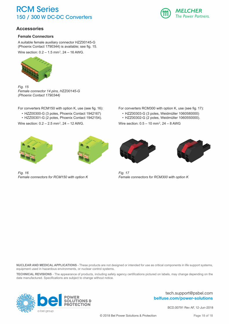
AccessoriesFemale ConnectorsA suitable female auxiliary connector HZZ00145-G (Phoenix Contact 1790344) is available; see fig. 15.Wire section: 0.2 – 1.5 mm2, 24 – 16 AWG.
Fig. 15Female connector 14 pins, HZZ00145-G(Phoenix Contact 1790344)
For converters RCM150 with option K, use (see fig. 16): • HZZ00300-G (3 poles, Phoenix Contact 1942167)
• HZZ00301-G (2 poles, Phoenix Contact 1942154).Wire section: 0.2 – 2.5 mm2, 24 – 12 AWG.
For converters RCM300 with option K, use (see fig. 17): • HZZ00303-G (3 poles, Weidmüller 1060580000)
• HZZ00302-G (2 poles, Weidmüller 1060550000).Wire section: 0.5 – 10 mm2, 24 – 8 AWG
Fig. 16Female connectors for RCM150 with option K
Fig. 17Female connectors for RCM300 with option K
NUCLEAR AND MEDICAL APPLICATIONS - These products are not designed or intended for use as critical components in life support systems, equipment used in hazardous environments, or nuclear control systems.
TECHNICAL REVISIONS - The appearance of products, including safety agency certifications pictured on labels, may change depending on the date manufactured. Specifications are subject to change without notice.