Embed Size (px)
Citation preview
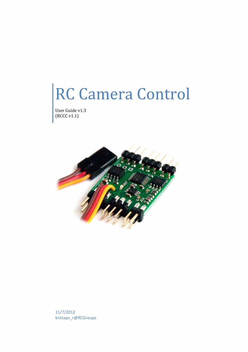
RC Camera Control User Guide v1.3 (RCCC v1.1)
11/7/2012 kristaps_r@RCGroups
1
INTRODUCTION
RC Camera Control board (RCCC) is multifunctional control board designed to for aerial photography or First Person Video flying.
RCCC has following features:
Camera shutter release control (Focus, Shutter and GoPro mode)
Video source selection (switch one of 3 video inputs to video output)
High current switch output (Turn On/Off LEDs …)
LiPo battery low voltage alarm
Sum PPM or 3 PWM input from RC receiver (Shutter, Video source, Switch)
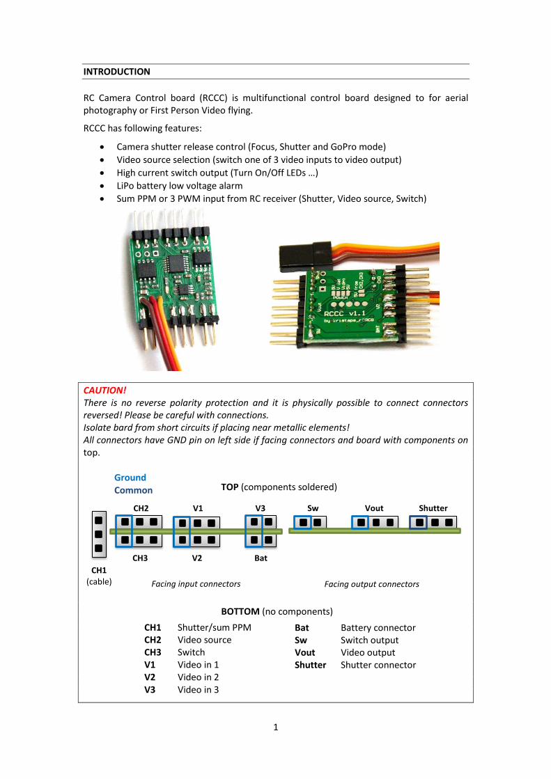
CAUTION! There is no reverse polarity protection and it is physically possible to connect connectors reversed! Please be careful with connections. Isolate bard from short circuits if placing near metallic elements! All connectors have GND pin on left side if facing connectors and board with components on top.
TOP (components soldered) BOTTOM (no components)
Ground Common
Facing input connectors Facing output connectors
CH2 V1 V3
CH3 V2 Bat
Sw Vout Shutter
CH1 (cable)
CH1 Shutter/sum PPM CH2 Video source CH3 Switch V1 Video in 1 V2 Video in 2 V3 Video in 3
Bat Battery connector Sw Switch output Vout Video output Shutter Shutter connector
2
CONNECTING
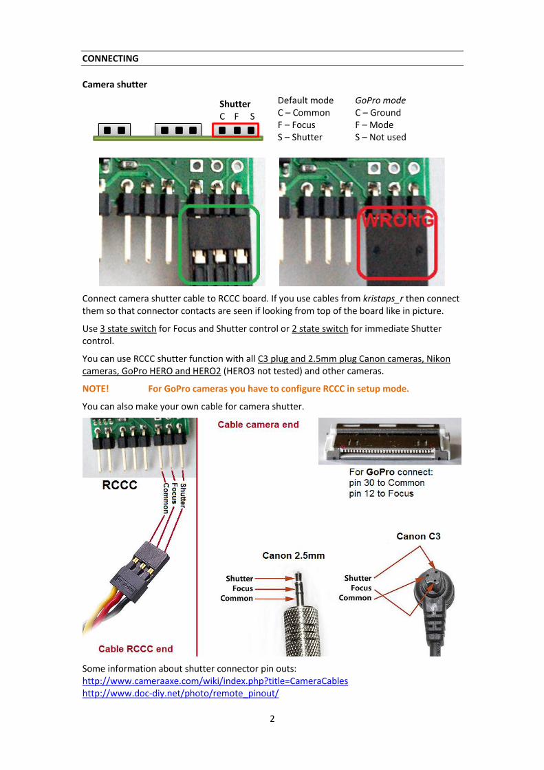
Camera shutter
Connect camera shutter cable to RCCC board. If you use cables from kristaps_r then connect them so that connector contacts are seen if looking from top of the board like in picture.
Use 3 state switch for Focus and Shutter control or 2 state switch for immediate Shutter control.
You can use RCCC shutter function with all C3 plug and 2.5mm plug Canon cameras, Nikon cameras, GoPro HERO and HERO2 (HERO3 not tested) and other cameras.
NOTE! For GoPro cameras you have to configure RCCC in setup mode.
You can also make your own cable for camera shutter.
Some information about shutter connector pin outs: http://www.cameraaxe.com/wiki/index.php?title=CameraCables http://www.doc-diy.net/photo/remote_pinout/
Default mode C – Common F – Focus S – Shutter
Shutter C F S
GoPro mode C – Ground F – Mode S – Not used
3
GoPro mode
To enable GoPro mode you have to configure it in setup step 4.
Shutter control in GoPro mode turns ON and OFF GoPro camera. To start recording after power ON you have to put GoPro in One Button Mode (see GoPro user manual).
It is possible to change way you turn GoPro ON and OFF by enabling GoPro toggle mode in setup.
If GoPro toggle mode is disabled GoPro follows state of RC transmitter switch dedicated to control GoPro camera. If switch is ON then GoPro will turn ON, if switch is OFF then GoPro will turn OFF.
If GoPro toggle mode is enabled then GoPro will change its power state each time when switch is changed from OFF to ON state. This is usable if you have momentary switch on your RC transmitter (like Trainer switch). Pushing switch will turn GoPro ON, pushing switch one more time will turn GoPro OFF.
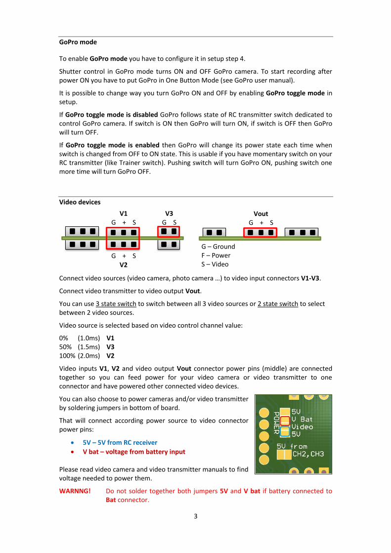
Video devices
Connect video sources (video camera, photo camera …) to video input connectors V1-V3.
Connect video transmitter to video output Vout.
You can use 3 state switch to switch between all 3 video sources or 2 state switch to select between 2 video sources.
Video source is selected based on video control channel value:
0% (1.0ms) V1 50% (1.5ms) V3 100% (2.0ms) V2
Video inputs V1, V2 and video output Vout connector power pins (middle) are connected together so you can feed power for your video camera or video transmitter to one connector and have powered other connected video devices.
You can also choose to power cameras and/or video transmitter by soldering jumpers in bottom of board.
That will connect according power source to video connector power pins:
5V – 5V from RC receiver
V bat – voltage from battery input Please read video camera and video transmitter manuals to find voltage needed to power them.
WARNNG! Do not solder together both jumpers 5V and V bat if battery connected to Bat connector.
V1 G + S
G + S V2
V3 G S
Vout G + S
G – Ground F – Power S – Video
4
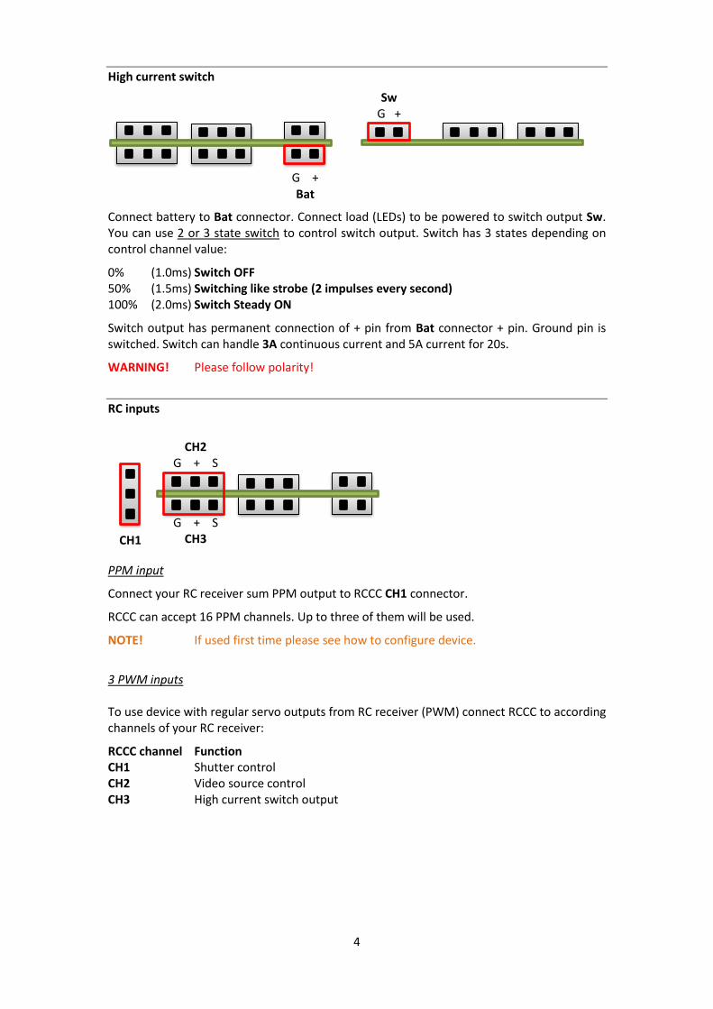
High current switch
Connect battery to Bat connector. Connect load (LEDs) to be powered to switch output Sw. You can use 2 or 3 state switch to control switch output. Switch has 3 states depending on control channel value:
0% (1.0ms) Switch OFF 50% (1.5ms) Switching like strobe (2 impulses every second) 100% (2.0ms) Switch Steady ON
Switch output has permanent connection of + pin from Bat connector + pin. Ground pin is switched. Switch can handle 3A continuous current and 5A current for 20s.
WARNING! Please follow polarity!
RC inputs
PPM input
Connect your RC receiver sum PPM output to RCCC CH1 connector.
RCCC can accept 16 PPM channels. Up to three of them will be used.
NOTE! If used first time please see how to configure device.
3 PWM inputs To use device with regular servo outputs from RC receiver (PWM) connect RCCC to according channels of your RC receiver:
RCCC channel Function CH1 Shutter control CH2 Video source control CH3 High current switch output
G + Bat
Sw G +
CH2 G + S
G + S CH3 CH1
5
START USING DEVICE
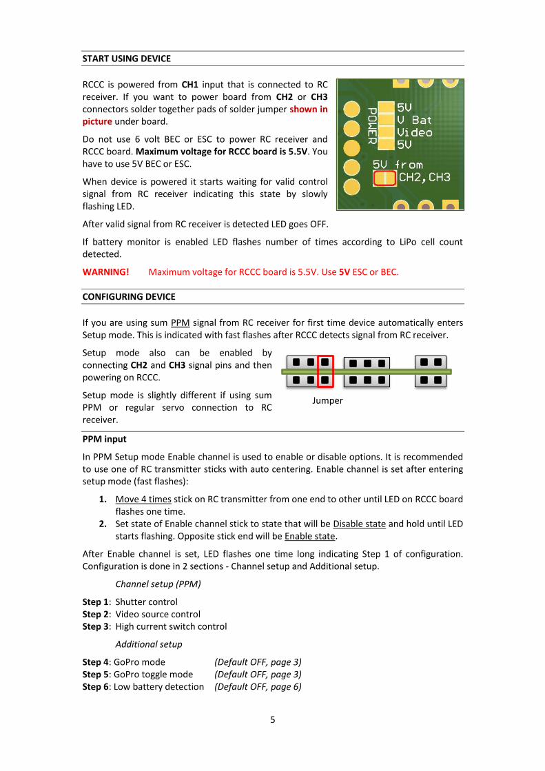
RCCC is powered from CH1 input that is connected to RC receiver. If you want to power board from CH2 or CH3 connectors solder together pads of solder jumper shown in picture under board.
Do not use 6 volt BEC or ESC to power RC receiver and RCCC board. Maximum voltage for RCCC board is 5.5V. You have to use 5V BEC or ESC.
When device is powered it starts waiting for valid control signal from RC receiver indicating this state by slowly flashing LED.
After valid signal from RC receiver is detected LED goes OFF.
If battery monitor is enabled LED flashes number of times according to LiPo cell count detected.
WARNING! Maximum voltage for RCCC board is 5.5V. Use 5V ESC or BEC.
CONFIGURING DEVICE
If you are using sum PPM signal from RC receiver for first time device automatically enters Setup mode. This is indicated with fast flashes after RCCC detects signal from RC receiver.
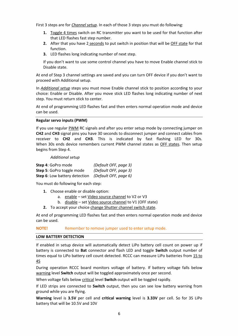
Setup mode also can be enabled by connecting CH2 and CH3 signal pins and then powering on RCCC.
Setup mode is slightly different if using sum PPM or regular servo connection to RC receiver.
PPM input
In PPM Setup mode Enable channel is used to enable or disable options. It is recommended to use one of RC transmitter sticks with auto centering. Enable channel is set after entering setup mode (fast flashes):
1. Move 4 times stick on RC transmitter from one end to other until LED on RCCC board flashes one time.
2. Set state of Enable channel stick to state that will be Disable state and hold until LED starts flashing. Opposite stick end will be Enable state.
After Enable channel is set, LED flashes one time long indicating Step 1 of configuration. Configuration is done in 2 sections - Channel setup and Additional setup.
Channel setup (PPM)
Step 1: Shutter control Step 2: Video source control Step 3: High current switch control
Additional setup
Step 4: GoPro mode (Default OFF, page 3) Step 5: GoPro toggle mode (Default OFF, page 3) Step 6: Low battery detection (Default OFF, page 6)
Jumper
6
First 3 steps are for Channel setup. In each of those 3 steps you must do following:
1. Toggle 4 times switch on RC transmitter you want to be used for that function after that LED flashes fast step number.
2. After that you have 2 seconds to put switch in position that will be OFF state for that function.
3. LED flashes long indicating number of next step.
If you don’t want to use some control channel you have to move Enable channel stick to Disable state.
At end of Step 3 channel settings are saved and you can turn OFF device if you don’t want to proceed with Additional setup.
In Additional setup steps you must move Enable channel stick to position according to your choice: Enable or Disable. After you move stick LED flashes long indicating number of next step. You must return stick to center.
At end of programming LED flashes fast and then enters normal operation mode and device can be used.
Regular servo inputs (PWM)
If you use regular PWM RC signals and after you enter setup mode by connecting jumper on CH2 and CH3 signal pins you have 30 seconds to disconnect jumper and connect cables from receiver to CH2 and CH3. This is indicated by fast flashing LED for 30s. When 30s ends device remembers current PWM channel states as OFF states. Then setup begins from Step 4.
Additional setup
Step 4: GoPro mode (Default OFF, page 3) Step 5: GoPro toggle mode (Default OFF, page 3) Step 6: Low battery detection (Default OFF, page 6)
You must do following for each step:
1. Choose enable or disable option: a. enable – set Video source channel to V2 or V3 b. disable – set Video source channel to V1 (OFF state)
2. To accept your choice change Shutter channel switch state.
At end of programming LED flashes fast and then enters normal operation mode and device can be used.
NOTE! Remember to remove jumper used to enter setup mode.
LOW BATTERY DETECTION
If enabled in setup device will automatically detect LiPo battery cell count on power up if battery is connected to Bat connector and flash LED and toggle Switch output number of times equal to LiPo battery cell count detected. RCCC can measure LiPo batteries from 1S to 4S
During operation RCCC board monitors voltage of battery. If battery voltage falls below warning level Switch output will be toggled approximately once per second.
When voltage falls below critical level Switch output will be toggled rapidly.
If LED strips are connected to Switch output, then you can see low battery warning from ground while you are flying.
Warning level is 3.5V per cell and critical warning level is 3.33V per cell. So for 3S LiPo battery that will be 10.5V and 10V
7
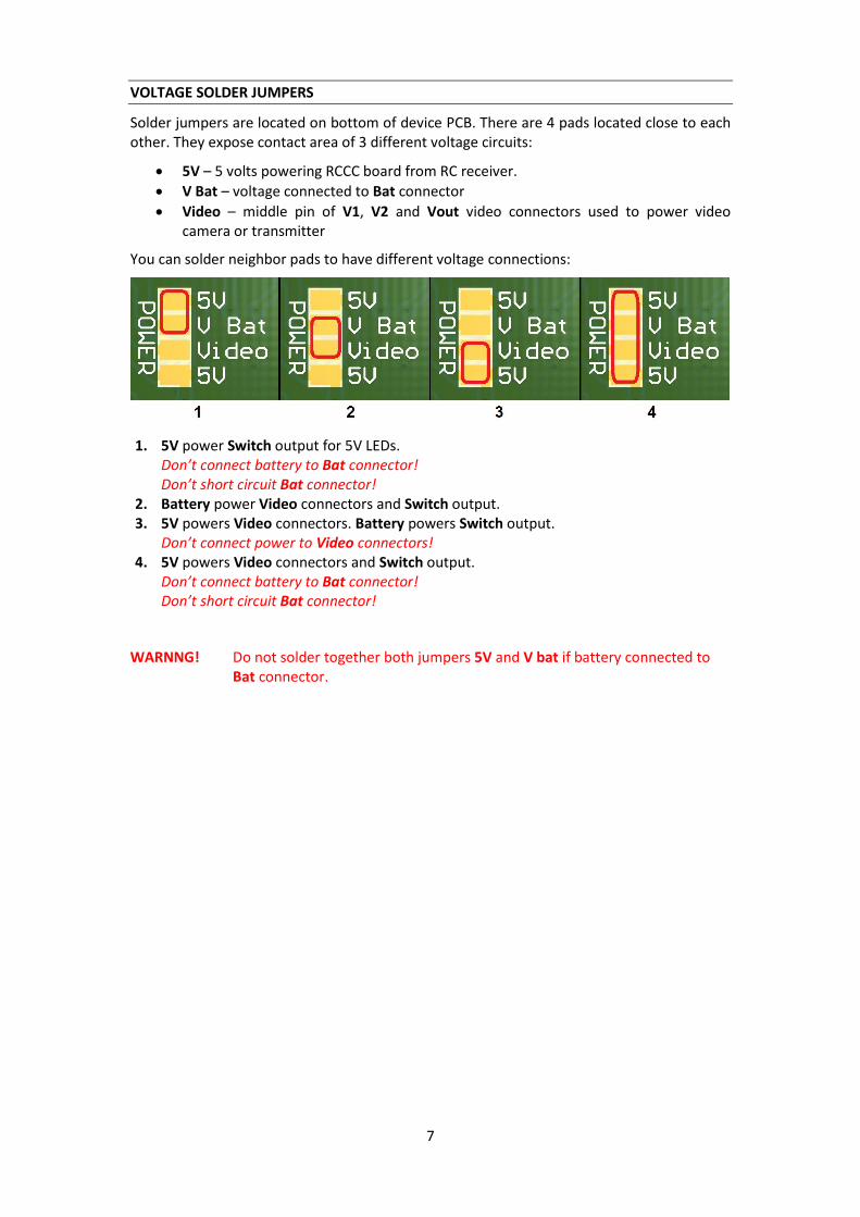
VOLTAGE SOLDER JUMPERS
Solder jumpers are located on bottom of device PCB. There are 4 pads located close to each other. They expose contact area of 3 different voltage circuits:
5V – 5 volts powering RCCC board from RC receiver.
V Bat – voltage connected to Bat connector
Video – middle pin of V1, V2 and Vout video connectors used to power video camera or transmitter
You can solder neighbor pads to have different voltage connections:
1. 5V power Switch output for 5V LEDs. Don’t connect battery to Bat connector! Don’t short circuit Bat connector!
2. Battery power Video connectors and Switch output. 3. 5V powers Video connectors. Battery powers Switch output.
Don’t connect power to Video connectors! 4. 5V powers Video connectors and Switch output.
Don’t connect battery to Bat connector! Don’t short circuit Bat connector!
WARNNG! Do not solder together both jumpers 5V and V bat if battery connected to Bat connector.
8
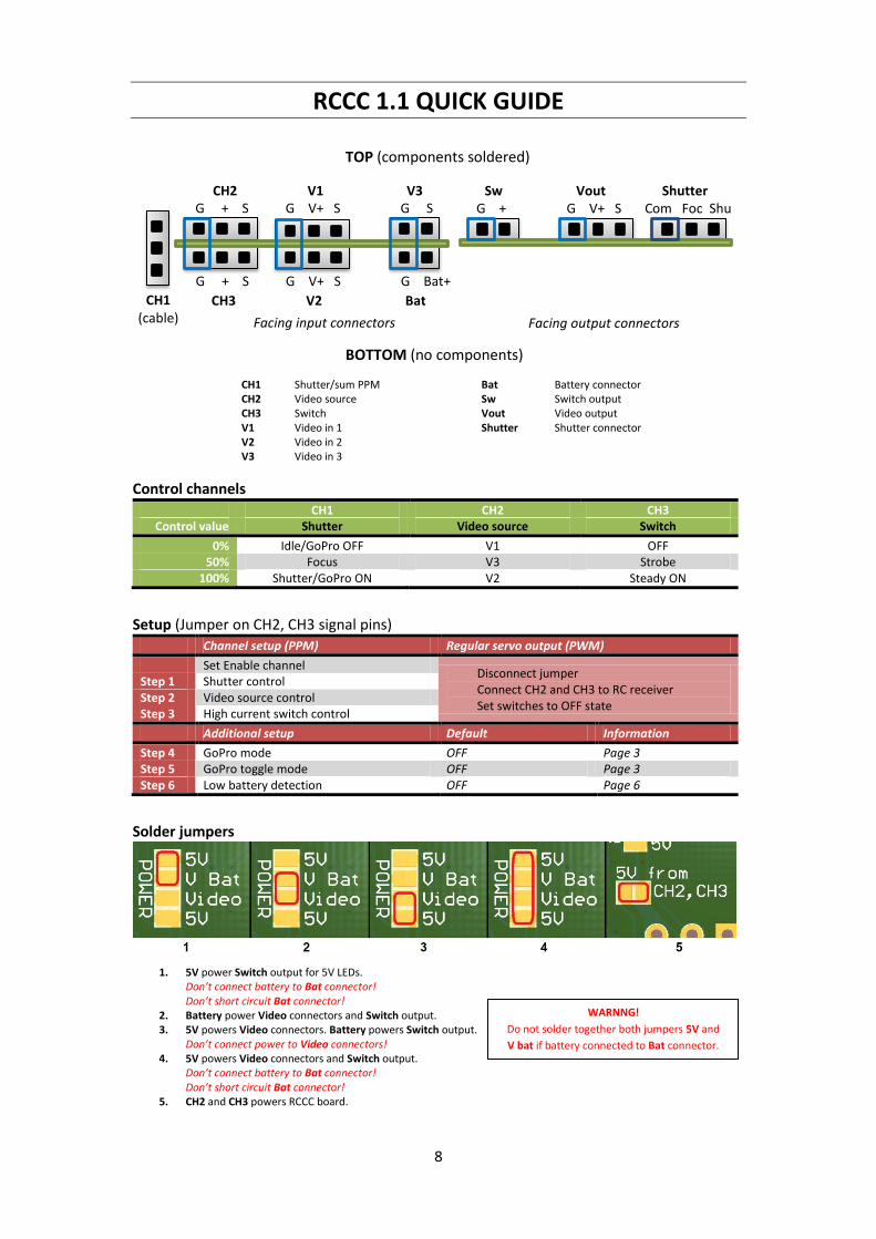
RCCC 1.1 QUICK GUIDE
Control channels
CH1 CH2 CH3 Control value Shutter Video source Switch
0% Idle/GoPro OFF V1 OFF 50% Focus V3 Strobe
100% Shutter/GoPro ON V2 Steady ON
Setup (Jumper on CH2, CH3 signal pins) Channel setup (PPM) Regular servo output (PWM)
Set Enable channel Disconnect jumper Connect CH2 and CH3 to RC receiver Set switches to OFF state
Step 1 Shutter control Step 2 Video source control Step 3 High current switch control
Additional setup Default Information
Step 4 GoPro mode OFF Page 3 Step 5 GoPro toggle mode OFF Page 3 Step 6 Low battery detection OFF Page 6
Solder jumpers
1. 5V power Switch output for 5V LEDs.
Don’t connect battery to Bat connector! Don’t short circuit Bat connector!
2. Battery power Video connectors and Switch output. 3. 5V powers Video connectors. Battery powers Switch output.
Don’t connect power to Video connectors! 4. 5V powers Video connectors and Switch output.
Don’t connect battery to Bat connector! Don’t short circuit Bat connector!
5. CH2 and CH3 powers RCCC board.
TOP (components soldered) BOTTOM (no components)
Facing input connectors Facing output connectors
CH2 V1 V3
CH3 V2 Bat
Sw Vout Shutter
CH1 (cable)
CH1 Shutter/sum PPM CH2 Video source CH3 Switch V1 Video in 1 V2 Video in 2 V3 Video in 3
Bat Battery connector Sw Switch output Vout Video output Shutter Shutter connector
G + S G V+ S G S G + G V+ S Com Foc Shu
G + S G V+ S G Bat+
WARNNG!
Do not solder together both jumpers 5V and
V bat if battery connected to Bat connector.


![DisCo: Display-Camera Communication Using Rolling Shutter ...wisionlab.cs.wisc.edu/wp-content/uploads/2016/07/a150-jo.pdfPresentation]: User Interfaces ... to rolling shutter, temporal](https://img.pdfslide.us/doc/110x75/5f872e6b5ce4d3048c44a748/disco-display-camera-communication-using-rolling-shutter-presentation-user.jpg)