Embed Size (px)
Citation preview

rBREAKOUT RESISTANCE OF OBJECTS
V) EMBEDDED IN OCEAN BOTTOM
by
Aleksandar S. Vesid
Report Number CR.69.031prepared for
U. S. Naval Civil Engineering LaboratoryPort Hueneme, California
under.Contract No. N62399-68-C-0043
Durham, North CarolinaMay, 1969
p
This document has been approved for public release and sale;its distribution is unlimited.
ABSTRACT
This study is devoted to factors affecting the magnitude of forceneeded to cause complete withdrawal of objects embedded in sediments ofthe ocean bottom. Following a literatare review, most discussions arecentered around the basic problem of a centrally loaded object pulled by
I a vertical force from a sediment with level surface. Considerations ofeffects of eccentric and inclined loading, as well as of slope of the
iocean bottom are added toward the end of the report.It is found that failure patterns in the overburden soil, which
greatly affect the magnitude of contribution of that soil to the break-4 out force, depend on the relative depth of the object, as well as on thetype of soil and extent of its possible remolding by the operation ofplacing the object. In undisturbed dense and stiff soils at relativelyshallow depths failure occurs in general shear, with a convex, torical
slip surface. In the case of compressible, sezri-liquid soils, as wellas in the case of significant remolding around the object during placing,this convex surface degenerates into a vertical cylinder. At greaterdepths only punching failure, similar to that occurring under deep foun-dations, is observed, regardless of soil type.
A theoretical analysis, based on the assumption that the soil be-haves at shallow depth as a rigid-plastic solid, shows better agreement
in the case of soft and loose soils than in the ca-e of stiff and dense
soils. This is, however, only apparently a paradox, as analogous com-parisons made with vertically loaded plates on soil surface show an in-triguingly similar trend.
Perhaps the least understood components of the breakout force arethose attributed to soil suction and to adhesion between the object andsurrounding soil. It appears that the problem of soil suction could betreated as a problem of pore-pressure difference on the two sides of theobject by pu21l-out loading.
It is suggested that uhe problem of breakout force may have a rela-
tively simple solution for soils having water contents above the liquidlimit, thus behaving as viscous liquids. There are reasons to believethat a similar approach, using a more complex rheological model, (suchas Bingham's), would be worth trying for at least semi-liquid soils with-in the plastic range.
it is, finally, recormended that the future research on breakoutforces be centered around the following four problem areas:
L~i

1) The effect of soil liquidity and/or compressibility on failurepattern in the overburden soil a!,d magnitude of breakout factors.
2) The effect of time on development of adhesion between objectsand the surrounding soil; the relationship between adhesion in te nsionand adhesion in shear.
3) The nature and magnitude of force of soil suction on objects;
the effects of load inclination ?nd eccent--icity on magnitude of thisforce.
4) The nature and magnit,ide of breakout force in liquid soils;connection between composition Fnd structure of such soils and theirrheological constants of lquid an, semi-liquid soils.
f1
II
ifi
I~

TABLE CF CONTENTS
Page
ABSTRACT
TABLE OF CONTENTS V
LIST OF FIGURES vi
Introduction I
Literature review 2
The basic problem 5
The effective weight of the object and the soil mass 5
The shearing resistance of overburden soil 7
Comparison of theory And experimental data 17
The effect of soil remolding 18
Effects of rate and character of loading 18
Contribution of soil adhesion 19
Contribution of soil suction force 20
Effects of ocean bottom slope 21
Effect of load inclination 22
Effect of eccentricity 24
Effect of soil liquidity 25
Summary and appraisal 25
Recommendations 26
REFERENCES 29
APPENDIX - SAMPLE PROBLEMS 33
V

LIST OF FIGURES
1. Basic problem of breakout forces 2
2. Variants of the problem of breakout forces 3
3. Shape of slip surface for circular buried objects 7
4. Observed shapes of slip surfaces caused by withdrawal of acircular plate from stiff silty clay (from Bhatnagar 16) 8
5. Breakou: factor F in sands 16q
6. Breakout factor F in clays 17c
7. Analysis of suction force as a pore-water stress difference
problem 21
8. Analysis of breakout of an object on sloped ocean bottom 22
9. Analysis of breakout by an inclined load 23
10. Analysis of breakout by an eccentric load 24
Vii
XI

Introduction
Increased interest in exploratic. and utilization of ocean re-
svjurces over the past decade has resulted in special attention for theproblem of breakout forces of objects embedded in sediments of the oceanb3ttom. This geotechnical problem is encountered in many marine opera-tions in both shallow and deep waters, which require the use of anchorsto transmit upward-directed forces to the ocean bottom. Typically, anymooring system for ocean surface or submerged platforms owes its stabil-ity to the ocean-bottom anchors (1). The problem appears equally oftenin design and construction of deep-sea habitats (2), as in design ofsalvage operations of sunken ships (3) or in repositioning of deep-seaplatforms (4). In all these situations the problem of breakout forcescan be defined as follows (Fig. 1):
Given an object of known shape, dimensions and weight, brought bysome operation to rest at a depth D below the ocean bottom. The objectis, thus, partially or fully embedded in the bottom sediments of knownphysical characteristics. Find the magnitude of force F needed tocause complete withdrawal of the object from the ocean bottom sediments.
The magnitude of force F depends, among other factors, upon its
direction, its position with respect to the centroid of the object aswell as upon the nature of connection between the force-transmitting
element and the object. The force can be generally applied in a verti-cal direction (Fig. 2a, b) or at an angle a to the vertical (Fig. 2c,d);in both cases it can act centrally as shown in Fig. 2a,c or eccentri-cally, as shown in Fig. 2b, d. The connection with the force-trans-mitting element (usually a cable) is normally moment-free, as shown inFigs. 2a-d; if it transmits a moment as well (Fig. 2e) the problem isessentially the same as that of an eccentrically loaded object (Fig.2b,d). The magnitude of force F may also be significantly affected bythe slcpe of t,- ocean bottom, which will generally be denoted by(positive as shown in Fig. 2f).
In this report we shall consider first the basic problem of acentrally loaded object pulled by a vertical force (a = 0) against ahorizontal bottom ( = 0), see Fig. 2a. Other cases will be considered,as appropriate, in subsequent sections. A brief literature reviewwill precede the discussions.
3

Literature Review
Published literature on the subject of breakout forces from oceanbottom is relatively scarce. It consists principally of three reportsdescribing the investigations performed during the last four years atthe U.S. Naval Civil Engineering Laboratory in Port Hueneme, California(3) (4) (5), see also (6). These investigations involved breakout testswith objects weighing up to 40,000 lb., which were forced into soils andrecovered at three different field locations, as well as in a large-scale laboratory facility. From results of tests in San Francisco BayMuga (4) (6) proposed an empirical formula for evaluation of breakoutforce. He also presented a numerical analysis of the plane-strainproblem of breakout of an object from an elastic-plastic solid. Assemb-ling all results available from NCEL investigations, Liu (5) presentedanother empirical correlation in dimensionless terms, which took intoaccount the time since embedment of the object, as well as the breakout
F
'7_
I •. . . . V . .I• .' .
Rv\
i: .
IR
Ca
Fig. 1. Basic problem of breakout force
2

I
if
F F
* . * * * * . . ** I * *
0 *:. ** 0:~'.i ** * *
.*I * *
I
4 .
.4. 4 * 4 U4..
H ~_____
b
I. . . 4.I., S
lj
4 . 4 . AttFig. 2. Varianti of the problem of breakout force
~ j 4
3
.1

time, already present in Muga's formula. He also showed that it was
very difficult to predict the breakout time to any reasonable accuracy.Anoth-er known investigation was conducted at the Southwest Research
institute Jn San Antonio, Tex~s (7), where plates weighing up to 200 lb.were lifted from the surface of a soil model (cind or clay) incide atank with simulated water pressures up to 5,000 psi. The principal find-ing of this preliminary investigation was that the breakout force depen-ded upon the size of the object, soil type as well as embedment time.It was also confirmed experimentally, that hydrostatic presure- up to3,000 psi did not have any effect on breakout force. The effects ofbreakout time or depth of embedment were not investigated.
In contrast "co limite& information available on breakout behaviorof objects in ocean bottom environment, quite extensive investigationsof pall-out capeAity of anchors in ordinary terrestrial soils have beenperformed in the past. The work prior to ..960 consisted largely oftesting of foundations for transmission towers and theorizing about themagnitude of soil resistance to pull-out (8, 9). Modern reseqrcn onthis subject started with a paper by Balla-(10), who determined theshape of slip surfaces for shallow anchor plates in dense sand and pro-posed a -ational method for analysis of pull-out forces based on ob-served shapes of these slip surfaces. Baker and Kondner (11) confirmedBalla's major findings regarding anchor plates in dense sa.d: howeverthey show.d thet aeep anchors behaved differently from shallow anchor:;.Mariupol'skii ('&), who also noted the difference in behavior of Inchorsat greater depth, proposed separate analytical procedures for aunalynisof shallow and deep anchors. Sutherland (13) presenfted well documentedresults of pull-out tests with model plates up to 6-in. in diameter inloose and dense sand, as well as with 94-in.-diameter shafts in mediumdense to dense sands. He found that the mode of failure varied alsowith sand density and showed that Balla's analytical approach may givereasonable results only in sands of some intermediate density. Kananyan(34) also presented well-documented results of pull-out tests with modelplates up to 48 in. in diameter buried in a deposit of loose to mediumdense fine sand. His experiments included one series of tests with in-clined plates pulled out by central, inclinel lcoAs in the direction ofthe plate axis. He observed similar failure patterns as the precedinginvestigators, with well-defined slip surfaces. In the case of inclinedplates, the pattern was unsyuumetrical and the movement of the soil par-ticles above the plate appeared to be predominantly vertical. Theultimate breakout forces generally increased with the inclination ofthe plates.
More recent research at Duke University involved testing of modelplates and piles in loose and dense sand (14), as well as in a verysoft clay (undrained strength of about 100 -b/ft 2 ), (15), and a stiffsilty clay (undrained strength about 1,000 lb/ft2), (1_). Mo-les offailure were investigted in greater detail: it was found thattransi-tion to deep anchor behavior occurred in very soft clay and loose sandat depths of only two to three plate diameters, as compared to fiveplate diameters in stiff clay and ten plate diameters in dense sand.These tests also revealed the .'elative importance of soil suction force
4

in very soft clay, which proved to offer the predominant resistance to
pull-out for all shallow anchors in soft clays. Some of these conclu-sions can be confirmed by analyzing the results of parallel investiga-tions made at Hydro-Electric Power Commission on Ontario and Nova ScotiaTechnical College (17). The latter inveztigations contain also some
data on pull-out capacity of model groups of piles, as well as on theeffect of sustained loading on ultimate pull-out force in cohesive soils.
The Basic Problem
Returning to the basic problem of a centrally loaded object pulledby a vertical force against a horizontal bottom (Fig. 1), it is not dif-ficult to find that the breakout force F consists of the following com-
ponents:(a) the effective weight of the object, W, including the weight
of the connecting cable;
/b) the effective weight of the mass of soil, W , involved inbreakout together with the object;
(c) the vertical component R of the forces of shearing resistance
ii R of the overburden soil along the slip surfaces separating that part ofthe soil involved in breakout from the rest of the soil mass;
(d) the vertical component CA of forces of adhesion c betweenthe skin of the object and adjacent soil;
(e) the soil suction force P , resulting from differences inpore-water stresses above and below the object, caused by attemptedcertical upward movement of the system.
The factors affecting the magnitude of individual components ofthe breakout force, listed above, are discussed and analyzed in the fol-
lowing paragraphs.
The Effective Weight of the Object and the Soil Mass
The determination of the effective weight U of the object posesno problems: it is always equal to the difference between the object's
total weight W ("weight in air") and the buoyancy in water, U
=W -u (1)
The effective weight of the involved soil mass can easily be de-termined if the effective unit weight 7' and the volume of that mass
are known. For the effective unit weight 7: we can use the formula:
(Gs_ w (2)
+e
5

where G is the specific gravity of solids, 7 unit weight of water and
e the void ratio of the soil. For saturated soil the latter quantity is
equal to
e= wG (3)
where w is the water content of the soil.
Should there be steady vertical seepage of gradient i in the soil
mass in question the apparent soil weight will be changed to
7" =7± 7 i (4)
where the plus sign applies to downward and the minus sign to upwardflow of water.
To determine the volume of soil involved in breakout, it is essen-
tial to know the exact shape of the slip surface in the soil.1The shape of this surface has been the object of extensive specu-lation in the past, mostly in connection with nnalysis of footings of
transmission towers subjected to vertical pull-out forces. On the basis Jof experiments cn model anchor plates in dense sand, as well as from
some theoretical considerations, Balla (10) suggested that the slip sur-
face for circular buried objects should be part of a torus, with a gen-eratrix consisting of a circle, such as that shcwn in Fig. 3. The circleshould meet the soil surface at statically correct angle e = 45 - 0/2
and the plate edge at kinematically correct angle 81 = 90 ° .
Observations in small-scale model tests with anchor plates andanchor piles at Duke University (14) (15) (16) proved that the shapeshown in Fig. 3 occurs only in the case of relatively shallow anchors indense sand or stiff silty clay. For shallow anchors in loose sand orsoft clay, the slip surface, though not clearly established, is closer
to being a vertical cylinder around the perimeter of the anchor.Thus, for objects embedded in loose and compressible sedments,
it is more reasonable to assume that the soil involved in breakout isessentially only soil immediately above the object. This may also proveto be a reasonable assumption in any case where the soil immediatelysurrounding the object is weakened by remolding. At the same time, theassumption of a torical slip surface (such as 01 in Fig. 3) will yieldthe maximum possible effective weight of the involved soil mass.
It may be added that the difference between the soil weight for anassumed torical slip surface, as ccpared with an assumed cylindricalslip surface, is small for relatively shallow and long objects (smallD/B and large L/B). However the difference can be very significant forcircular objects at greater depth.
It should be noted that very deep anchors do not fail in general
shear failure such as that shown in Fig. 3, regardless of the relativedensity of the soil. Experiments indicate that they can be moved ver-tically for considerable distances by producing a failure pattern simi-lar to punching shear failure in deep foundations (18). Only afterbeing pulled up to relatively shallow depths may they eventually produce
general shear failures such as that shown in Fig. 3. This is illustratedin Fig. 4, taken from Ref. 16.
:6

I1 0
I
l' O
SI \\\
Fig. 3. Shape of slip surface for circular buried objects
The c?'itical relative depth D/B above which embedded objectsshould behave as shallow anchors depends on the relative density of thesoil and possibly some other yet unclarified factors. Available exper-imental evidence from experiments with 3-in.-diameter plates suggeststhat this limiting depith 1)/B in sand may increase from perhaps 2 for avery loose deposit to over 10 in a very dense deposit (14). In verysoft bentonite clay the limit is at vbout D/B = 2, (15)- wile in astiff silty clay f.t appears to be around D/B = 5 (16
The Shearing Resistance of the Overburden Soil
In all cases where a definite slip surface such as that shown inFig. 3 appears, the vertical component of the shearing resistance ofthe overburden soil, R , can be determined by an appropriate analysis.A rigorous computation by the methods of theory of plasticity is verydifficult, unless some assumptions are made regarding the shape of theslip surface and the distribution of stresses along that surface.
Balla (10) has proposed a simplified analysis of this problemfor a circular anchor plate, under the assumptions about the shape ofthe slip surface mentioned in the preceding paragraph and shown inFig. 3. To find the distribution of' stresses in the slip surface heapplied Kbtter's equation and assumed that the distribution in theaxially symetrical case is the same as in the plane strain case. Theresult of his computations is presented by an expression of the form:
71

DISTANCE FROM (. (in.)015 10 5 1 5 10 15II
0
•\ ,, I .d /o*""'. ", ". ' 4-' / ...* " '" -"--
II .,
C"
- l% I,
2(I: I20iI
151
CII
20
5/16 Dia. ShaftIT
I I - 3"Dia -
Fig. 4. - Observed shapes of slip surfaces caused by withdrawalof a circular plate from stiff silty clay (from Bhatnagar, 16)
T

I
R F2(p, A)cD2 + F X)7D3 (5)
in this expression c and € are the strength characteristics of the soil(defining a Coulomb-Mohr failure criterion in a linear form), 7 is theeffective weight of the soil, and F2 and F are two complex functions ofthe angle of shearing resis3tance 0 of the oil and of the relative depthX = D/B of the embedded circular anchor. Balla's paper (10) containsnumerical values of factors F2 and F3, which, unfortunately, appear tobe incorrect.
A different analytical approach to this problem is available fromthe solutions proposed by Vesid' et al for the problem of expzrnsion ofcavities close to the surface of a semi-infinite rigid-plastic solid(19). These solutions give the ultimate radial pressure q0 needed to
break out a cylindrical or a spherical cavity of radius R placed at adepth D below the surface of the solid. They are presented in the form
qo = cF + 7DF (6)
where F and F are the cavity breakthrough factors, which depend on theshape and relative depth of the cavity, as well as on the angle of shear-ing resistance of the soil, As shown in Ref. 14, these solutions can beapplied to the problem of anchor plates. They contain essentially thevertical component R of the soil resistance, plus the weight of the soilabove the cavity, bo~h reduced to the area of the plate. As such theycould be used directly for embedded spheres or embedded horizontalcylinders. For embedded plates the equation (6) is corrected to
R +Wv S c + q (7)q - -2-cF +7Y(7
where F and F are plate bre out factors. It can be shown that, for
any pl e . However, for a circular plate:
F + 1 B ( 8 a)q q D
while for a long rectangular plate:
TFB = F' (8b)
For other shapes the difference in weight between the volume of theobject protruding above its maximum width and the corresponding volumeof overburden soil may be included, if significant. It should be em-phasized that the expressions (6) or (7) include both R and W reducedV sto the maximum area of the embedded object, measured perpendicularly totge applied breakout force F. The magnitude of factors F = F , F andF for circular anchors and 'actors F= - F4 and F' for long-regtang-uar anchors are given in the following Tables 1 and
9

Table 1
HORIZONTAL CYLINDER OR
LONG RECTANGULAR PLATE
BREAKOUT FACTORS
(after Vesi' & al. 1965)
0.5 1.0 1.5 2.5 5.0
0.81 1.61 2.42 4.o4 8.070.21 o.61 0.74 0.84 0.92
1.00 1.00 1.00 1.00 1.00
0.84 1.68 2.52 4.22 8.43100 0.30 0.77 0.99 1.26 1.75
1.09 1.16 1.25 1.42 1.83
o.84 1.67 2.52 4.19 8.5720° 0.38 0.94 1.23 1.67 2.57
1.17 1.33 1.49 1.83 2.65
0 0.79 1.58 2.37 3.99 7.89030 .45 1.03 1.45 2.03 3.301.24 1.47 1.71 2.19 3.38
0.70 1.40 2.11 3.51 7.020.51 1.19 1.61 2.30 3.831.30 1.58 1.87 2.46 3.91
0 0.58 1.17 1.75 2.92 5.84500 .53 1.25 1.70 2.44 4.12
1.32 2.04 1.96 2.60 4.20
First number F' = F' Second number F' (cylinder)c c q
Third number F'q (long rectangular plate)
10

Table 2
SPHERE OR CIRCULAR PLATE BREAKOUT FACTORS
(after Vesi6 & al, 1965)
SD/B
/ 0.5 1.0 1.5 2.5 5.0
0 1.76 3.80 6.12 11.6 30.300 0.33 0.67 0.78 0.87 0.93
1.00 1.00 1.00 1.00 1.00
0 1.87 5.10 6.69 13.0 36.0i0 0.51 1.04 1.37 1.95 3.60
1 1.18 1.37 1.59 2.08 3.67
1.90 4.23 7.01 13.9 38.920 0.69 1.42 1.98 3.12 6.64
1.36 1.75 2.20 3.25 6.71
0 1.84 4.19 7.06 14.3 41.63o 0.85 1.78 2.57 4.28 9.82
1.52 2.11 2.79 4.41 9.89
1.69 3.95 6.79 14.2 42.7400 0.98 2.08 3.08 5.32 12.9
2.65 2.41 3.30 5.45 13.0
1.47 3.53 6.19 13.3 41.6500 1.06 2.28 3.34 6.14 15.6
1.73 2.61 3.56 6.27 15.7
First number F (sphere or circular plate)c
Second number F (sphere)q
Third number P (circular plate)q
waw-a11

:!j
A somewhat different approach to the problem of soil resistance inbreakout has been attempted by Muga (4, 6). He has developed a numeri-cal procedurre, based on the discrete-element model introduced by Harperand Ang (31), for analytical determination of the breakout force. Thesoil in this analysis is assumed to behave as a homogeneous elastic-perfectly plastic solid, following the Huber-Mises yield criterion inthe plastic state. A good agreement between the results of this analy-sis and the experimental data from the San Francisco Bay was reported,at least for the soil in question - a highly plastic clay. In view ofthe yield criterion used it should not be expected that the analyticalmethod used could be applied to other types of soil. An adaptation of
the same procedure to other yield criteria, in particular to Coulomb-Mohr's is, in principle, possible, and should be attempted.
Another analytical approach to the same problem can be found in thementioned paper by Mariupol'skii (12). He determined the shape of theslip surface and the state of stress in the wedge of soil above theshallow anchor by using the following two assumptions: (1) that themximum shear stress is mobilized in every vertical cylindrical surface(such as 11' in Fig. 3) around the anchor axis; (2) that failure occursin tension at different points along a line such as 01 in Fig. 3 when-ever the vertical shear force exceeds the shearing strength along thevertical cylindrical surface over which it is to be transmitted.
Mariupol'skii's solution can be written in the following form:
2 B2 1 - (Bo/B)2 + 2 K tan 0 D/B + hc D/B( -B)- (Bo/B)2 - 2nD/B 7D (9)
B
where F is, as before, the breakout force, W effective weight of theanchor, D the depth and B the diameter of the circular anchor plate,B the diameter of the anchor shaft, 7 the effective weight of the soilafove the anchor, c and strength chdracteristics of the soil, K thecoefficient of lateral earth pressure in the soil wedge above the anchorand n -025 0 an eipirical function of the angle of shearing resis-tance *of the soil (4 - in degrees).
Since the values of the parameter n were determined from author'sexperiments, the reported agreement of theory and experiments is ofvery limited meaning. It should be noted that the assumptions made inanalyzing the state of stress in the soil wedge above the anchor areentirely arbitrary and in contradiction with the elementary theory ofearth pressure.
Mariupol'skii has also presented a solution for the soil resistanceto pullout of a deep anchor. This solution is based on the assumptionthat the work done by the anchor during vertical displacement shouldbe equal to the work needed to expand a vertical cylindrical cavity ofradius R = B /2 to the radius R = B/2. Using the same notations asabove, tfe ultimate breakout force F is given by:
12)

II
n/4(B2 -2B
F =W+ TBo[D- B + Bof 1-05 t P (10)
where f is the unit skin resistance along the stem of the anchor (ofradius ) and p is the ultimate pressure for expansion of a deep0cylindrical cavity. Mariupol'skii determines thie ultimate pressure bytrial and error from a lengthy equation. However, this could be donemore conveniently by using a rigorous solution of this problem given byVesi (32, 33) in the following form:
Pu = cF ' + 7DFq' (11)p c q
Here F ' and F represent cylindrical cavity expansion factors:c q
sineI 1+ sine
F' = (1 + sin 0) 2 cos (12)
Fc q(F I -I) cot c (13)c q
The quantity I represents the rigidity index of the soil, defined inr
terms of strength characteristics c, O and deformation characteristics, v of the soil as:
E (14)r (1 + v) (c + 7D tan 0)
It should be noted that for c = 0
F q=1 (15)q
I. IF l -n +1in()+1 (16)c
Numerical values of factors F ' and F ' for different values of 0 andI are given in Table 3. c qr The derived solution is based on assumption of no volume change in
the plastic zone surrounding the cavity. To introduce the effect of
I' volume change occurring in that zone as well, it is nec.'ssary to evalu-ate its average volumetric strain, A. A relatively simple procedure ofdoing this is outlined in Ref. 19. It is shown in the same reference
I '
13 .

that, once Ais known, the same equations (12) and (15) resp. (15) and
(16), c,n be used however with a reduced rigidity index !' defined as:rr
I= r _ (17)rr 1 IrA v' Ir
1 _ ..2 cos 4
where ' is the volume change factor for a cylindrical cavity. Numeri-
cal values of ' have been computed and assumbled in Table 4.V
Table 3CYLINDRICAL CAVITY EXPANSION FACTORS
(after Vesic, 1963)
10 20 50 100 200 500 1,000
00 2.6 3.3 4.2 4.9 5.6 6 5 7.21.0 1.0 1.0 1.0 1.0 1.0 1.0
50 2.7 3.5 4.7 5.6 6.5 7.9 9.01.2 1.3 1.4 1.5 1.6 1.7 1.8
10 2.8 3.7 5.1 6.2 7.6 9.5 11.11.5 1.7 1.9 2.1 2.3 2.7 2.9
15 2.9 3.8 5.4 6.8 8.5 11.0 13.31.8 2.0 2.5 2.8 3.3 4.0 4.6
20° 2.9 4.0 5.8 7.4 9.4 12.6 15.52.1 2.4 3.1 3.7 4.4 5.6 6.6
5° 2.9 4.1 6.o . 10.2 14.0o7.
; 4 2.9 3.8 4.7 5.7 7.5 9.3S0 2.9 4.1 6.2 8.3 10.9 15.4 19.9
2.7 3.4 4.6 5.8 7.3 9.9 12.5
35 2.9 4.2 6.4 8.6 11.5 16.8 22.03.0 3.9 5.5 7.1 9.1 12.7 16.5
400 2.9 4.2 6.5 8.8 12.0 17.7 23.73.4 4.5 6.4 8.4 11.1 15.8 20.9
45 2.9 4.1 6.5 9.0 12.3 18.3 24.9. , 3.8 5.1 7.5 10.0 13.3 19.3 25.9
500 2.8 4.0 6.4 9.0 12.4 18.9 25.8
4.3 5.8 8.6 11.7 15.8 23.5 31.8
Upper Number F'0 Lower Number F'q.
14

iI
I!
Table 4VOLUME CHANGE FACTORS C ' FOR A CYLINDRICAL CAVITY
(after VesYc et al 1965)
1 0.01 0.02 0.03 0.014 0.05 0.10 0.15
15o0.975 0.951 0.928 o.9o o.889 0.795 0.71O 0.975 0.953 0.950 0.909 0.889 0.800 I0.72815 0.97q 0.951 0.928 0.906 o.885 0.795 0.717
5 30 0.973 0.945 0.920 0.896 0.874 0.776 0.69845 0.965 0.935 0.905 0.075 0.850 0.738 0.653
i0 0.953 0.909 0.870 0.833 0.800 o.667 0.57215 0.951 0.906 0.866 0.829 0.795 0.659 0.563
10 30 0.945 0.896 0.852 0.812 0.776 0.655 0.53645 0.928 0.875 0.825 0.780 0.739 0.586 o.485
0 0.909 0.833 0.769 0.714 0.667 0.500 0,40015 0.906 0.829 0.762 O.706 o.659 o.2491 o.591
20 30 0.896 0.812 0.743 0.683 o.634 0.464 0.36645 0.875 0.779 0.702 0.639 o.586 0.414 0.320
0 0.800 0.667 0.57? 0.500 0.445 0.286 0.21115 0.795 0.659 0.563 o.492 o.2431 0.279 0.205
50 30 0.776 0.635 0.536 0.465 0.409 0.257 0.18745 0.739 0.586 o.484 o.2414 o.361 0.221 0.158
0 o.667 0.500 O.4oo 0.333 o.286 o.167 0.11815 0.659 0.3491 0.92 0.326 0.278 0.162 0.114
10 30 o0.634 o.465 0.366 0.302 0.258 o.148 0.10445 0.585 o.414 0.320 0.261 0.211 0.124 O.086
0 0.500 0.333 0.250 0.200 o.167 0.091 0.06315 o.493 0.326 0.242 o.194 o.162 O.088 O.060
200 30 o.465 0.302 0.224 0.178 0.148 0.080 0.05545 0.414 0.262 0.191 0.150 0.124 0.066 0.045
0 0.286 0.167 0.118 0.091 0.074 0.038 0.02615 0.278 o.162 o.114 0.088 0.072 0.036 0.025
500 30 0.257 0.147 0.103 0.080 0.065 0.033 0.02745 0.221 0.124 0.086 0.066 0.054 0.027 0.019
0 o.167 0.091 0.063 0.048 0.038 0.020 0.01315 o.162 o.088 0.061 0.046 0.037 0.019 0.012
10300 30 0.148 0.080 0.0q5 0.042 0.034 0.017 0.01145 0.124 oo66 o.045 0.034 0.028 0.014 0.009
15

OD4
LT
II
Q IL ZO-
0~ L.
to- .U
-
'~ '~\ "'
1 AG
E -0
0 0 0
- -.- %
1 C16

4
Comparison of Theory and Experimental Data
Comparisons of observed shearing resistances of the overburden soil
with the magnitudes computed by the Vesic solution, as given in the pre-ceding paragraph, are presented in Figs. 5 and 6. Both figures show theexpected trend of increase of observed breakout factors with depth onlyat shallow depths. For each soil type there is a characteristic rela-
tive depth D/B beyond which the anchor plate starts behaving as a deepanchor and beyond which breakout factors reach constant, final values.As mentioned earlier this characteristic relative depth for sands in-
creases with relative density from about 5 for loose sands to over 10for dense sands (Fig. 5). For clays it also appears to increase from
about 2 for very soft clays to about 5 for stiff clays (Fig. 6).Though the observations confirm the expected trend of increase of
breakout factors with depth, they also show that the absolute magnitude
of observed factors does not generally agree with theory. The difference
IZI ~Soft y- it Cly0 3 9 O
9 --
3 1 0
0 3 4 e6 t t
SF
5
DUKE TESTSOX P1 LI su
0 Soft Bentonite Clay 483 49 0.75
All tests with 3 i. dia. plate.2 Suction in soft cloy (2.3 lb/in2) deduCted. 4
RELATIVE DEPTH D/B
Fig. 6. Breakout factor F in clays
17
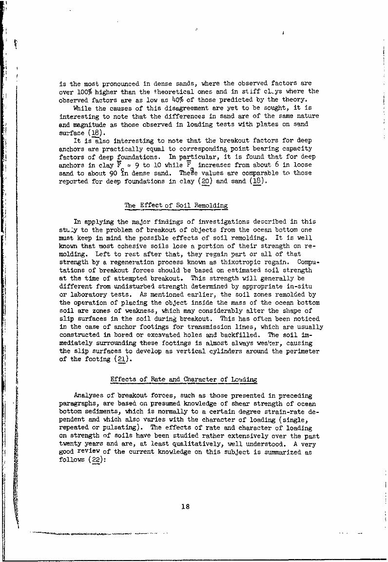
is the most pronounced in dense sands, where the observed factors are
over 100% higher than the theoretical ones and in stiff clys where the
observed factors are as low as 40% of those predicted by the theory.
While the causes of this disagreement are yet to be sought, it is
interesting to note that the differences in sand are of the same nature
and magnitude as those observed in loading tests with plates on sand
su':face (18).It is also interesting to note that the breakout factors for deep
anchors are practically equal to corresponding point bearing capacity
factors of deep foundations. In particular, it is found that for deep
anchors in clay F = 9 to 10 while F increases from about 6 in loosesand to about 90 in dense sand. Thege values are comparable to thosereported for deep foundations in clay (20) and sand (18).
The Effect of Soil Remolding
In applying the major findings of investigations described in thissttly to the problem of breakout of objects from the ocean bottom onemust keep in mind the possible effects of soil remolding. It is wellknown that most cohesive soils lose a portion of their strength on re-
molding. Left to rest after that, they regain part or all of thatstrength by a regeneration process known as thixotropic regain. Compu-tations of breakout forces should be based on estimated soil strengthat the time of attempted breakout. This strength will generally bedifferent from undisturbed strength determined by appropriate in-situor laboratory tests. As mentioned earlier, the soil zones remolded bythe operation of placing the object inside the mass of the ocean bottomsoil are zones of weakness, which may considerably alter the shape ofslip surfaces in the soil during breakout. This has often been noticed
in the case of anchor footings for transmission lines, which are usuallyconstructed in bored or excavated holes and backfilled. The soil im-mediately surrounding these footings is almost always weaker, causingthe slip surfaces to develop as vertical cylinders around the perimeterof the footing (21).
Effects of Rate and Character of Lcading
Analyses of breakout forces, such as those presented in precedingparagraphs, are based on presumed knowledge of shear strength of oceanbottom sediments, which is normally to a certain degree strain-rate de-pendent and which also varies with the character of loading (single,repeated or pulsating). The effects of rate and character of loadingon strength of soils have been studied rather extensively over the pasttwenty years and are, at least qualitatively, well understood. A verygood review of the current knowledge on this subject is summarized asfollows (22):
18

1) For a single load application there is little variation in
effective strength of saturated sands as the rate of loading varics from
very fast (say 10 milliseconds to failure) to very slow (say 10 hours to
failure). However under very fast loads there may be apparent strength
increase due to negative pore-water stresses, if the sand density is
kabove critical as well as apparent strength decrease due to positive
pore-water stresses, if the sand density is below critical, (23).
2) Under very fast, repeated loading, almost total loss of appa-
rent shear strength may occur in sands, even at densities far above
critical (24). This phenomenon, attributed to build-up of pore-water
pressures, had caused a number of catastrophic failures during earth-
quakes (25) and is, in all likelihood, responsible for flow slides in
submarinecanyons.3) For a single load application there is in cohesive soils a
strength increase under very fast loads and a strength decrease undervery slowly applied loads. This phenomenon has been attributed toviscous effects in adsorbed water surrounding active soil particles.
The strength typically inacreases twofold if the time to failure is re-
duced from one hour to 5 milliseconds, and may be reduced to as littleas 50% of the one-hour value, if the load is sustained over several
months. For obvious reasons, this effect should increase with increasedclay content and increased activity of soil minerals and must become
more and more pronounced as the liquidity index of soil increases toward1 (the latter effects will still be discussed in subsequent paragraphs).
4) Repeated loading causes some loss of strength of cohesive soils
as well, though the loss is rarely as spectacular as that in cohesion-less soils (26). This effect increases considerably with the amount ofstress increments applied, as well as with the soil sensitivity to re-molding.
5) Vibratory loads cuase generally loss of strength of both co-hesionless and cohesive soils, though the loss is much more pronouncedin the former. The amplitude and frequency of vibrations as well ascharacteristics of the footing in contact with 'he soil affect stronglythis phenomenon (27). Very little is known, however, in quantitative
sense about the response of Tootings to vibratory loads in pullout.
Contribution of Soil Adhesion
Cohesive soils, containing active minerals, will develop adhesionin contact with aLmost any material. The process is of physico-chemi-cal nature and requires some time.
Experiences with steel, concrete and wood piles seem to indicatethat, at least in soft soils, the adhesion equals or exceeds the un-drained shear strength after a period of a few days to, perhaps, sixmonths. Little is known about the development of adhesion within thefirst hours or days after the objects have been brought into contact
with soil.
19
I

/B
It should be noted that development of adhesion is parallel to theprocess of regeneration of shear strength of soils. Comparative studiesof development of both with time for at least some soil types and objectmaterials would be highly desirable.
Most of known adhesion studies were concerned with measurements ofresistance to shear. However in the breakout problem we have to dealalso with resistance to tension between the buried object and the under-lying soil. Very little, if anything, is known about such a force,except that is exists.
Contribution of Soil Suction Force
Penetration of an object through ocean bottom soil before coming torest, causes some excess total stresses underneath, which may be takenmostly by excess pore-water stresses. If the object has been resting atthe bottom for a sufficiently long time, at least a portion of pore-waterstresses may have been dissipated.
On application of breakout force the overburden soil immediatelyabove the object is heavily compressed, while the underlying soil is re-lieved from stress. Unless the soil is so highly pervious as to respondimmediately to stress changes, there will be increase of pore-waterstresses above the object and decrease of pore-water stresses below the
object. The difference results in a suction force.Very little is known about this force in any general sense. The
measurements in Duke tests (15) with 3-in.-ciameter plate anchors indi-cated an average suction pressure of 2.8 psi. This pressure is signi-ficantly higher than the measured adhesion of 0.5 psi between this soiland the anchor plate. (It should be noted that the indicated value wasmeasured with piate on soil surface and that the suction pressure at somedepth might be still higher.)
A possible way of analyzing the suction pressure is suggested in
Fig. 7. If the initial stress conditions u above and below the ob-ject, as well as total stress increments Aa imposed by object withdrawalare known, the pore pressure increments Au can be determined by appropri-ate tests on undisturbed soil samples. Recent research on yield behaviorof soils at Duke (28) offers also the possibility of pre-determining thesepore pressure increments analytically if the basic strength characteris-tics c', 0' of the soil are known. In either case the difference in pore-pressure increments on the two sides of the objects represents the maxi-
mum possible suction pressure, which would occur whenever the rate ofload application is must faster than the rate of dissipation of pore-water stresses. To find the breakout time in the situation where a known
sustained load is applied, one could develop, in principle, the neededsolutions by using the three-dimensional theory of consolidation.
It should be observed that the solutions of this kind could be usedonly as long as the liquidity index of the soil is low enough that nosignificant flow of soil itself occurs toward the potential cavity formedunder the -object. P approaches for lIqud o s, which, for obvi-ous reasons, must be basically different, will be discussed a little laterin the report.
20

Effect of Ocean Bottom Slope
The preceding considerations were limited to the basic case of break-out from horizontal ocean bottom. Shculd the ocean bottom be sloped atan angle P to the horizontal, the weiglt mrc1 resistance of the soil massopposing breakout will be different. As in the preceding case, an analo-gy can be found with the problem of expansion of a cavity close to thesurface of a sloped terrain (Fig. 8). This problem has been solved re-cently at Duke, in connection with studies of the cratering problem (29).The solution indicates that the ultimate breakout pressure of shallow
objects can be found by using the same equations and factors as in thecase of an horizontal bottom. It is necessary, however, to replace thedepth D in Eqs. 6 or 7 by the distance of least resistance D , and theeffective weight 7 oa7 the soil by its component 7 cos P in t~e directionishes when the slope angle P becomes equal to , a correction factor
such as sin ( - 6)/sin should be used for that resistance. Regarding
F-W+wvv +Rv +Ca+Pw
Pw= AudA* . . ,. ..
AA
*. \ . . •
WS
• * . J . .
,_.r •Pori&..• " -\" water P•
* . * t .
Fig..7. ---ys~ of sucton'or•
210
212

the breakout pressures of deep objects under a slope the available infor-mation suggests that they should be no different from those under a hori-
zontal ocean bottom.
Effect of Load Inclination 0IIn the case of central loads acting at an angle different from 90
to the ocean bottom, the failure pattern in the soil mass is changed,becoming unsymmetrical with respect to the line of least resistance (Fig.
9). For shallow objects the analysis can be performed by assuming arealistic shape of slip surfaces, such as that shown in Fig. 9, and usingthe conventional earth pressure theory, see Ref. 30. It is significantto note that the only known experimental investigation of the effect ofload inclination, made with plates in fine sand (34), showed an increaseof breakout force with inclination of the plate. As the incident angle
R .R
F f
rig. 8. Analysis of breakout of an object on sloped ocean bottom .
22

a (Fig. 2c) increased from 0 to 450 with all other variables remaining
the same, the breakout force was practically doubled. The object in
question - a circular stel plate - was placed perpendicularly to theapplied load.
It should be of great interest to investigate also the breakoutphenomena with inclined loads acting at angles different from 90 to the
major plane of the ob.'ect. In such cases one should expect the objectto rotate prior to pullout - as long as the load connection allows suchrotation. This may change the failure pattern in the soil and alsocause significant difference in the soil suction force. Analyses ofthis kind, nonexistent at present, should be of great practical interestto the ocean technologist.
IW
CA
Fig. 9. Analysis of breakout by an inclined load
23..................

F
'"
\ WW
\ I
R2"0
it. 10. Analysis of breakout by an eccentric load
Effect of Load Eccentricity
In the case of eccentrically applied loads, the rotation of theobject prior to pullout must be very significant, resulting in a fail-ure pattern quite different from those occurring under central loading.A possible failure pattern is shown in Fig. 10. n e center of rotationis located below, causing plastic failure on both sides of the object.Suction forces P. acting are forming a couple, thus balancing each oth-er, at least in part. This may explain why it is often so much easierto pull-out an object from ocean bottom by pivoting. Analyses such asthat shown in Fig. 10 can be very helpful in determining the most favor-able position for application of the breakout force in a salvage opera-tion. In view of complete absence of experimental information on thissubject, the analyses should be accompanied by small-scale tests.
24i

Effect of Soil Liquidity
As mentioned earlier, all the preceding analyses are, in principle,
applicable to the computation of breakout force in media which possess
some finite shearing strength. These include, theoretically, all cohe-
sionless soils, such as sand, as well as cohesive soils, such as clay,
at water contents below the liquid limit. However, soils at water con-
tents above the liquid limit have practically no residual shearing
strength, at least when remolded or sheared at large strains. For such
soils a fundamentally different apptoach to analysis of breakout force
should be attempted: they should be treated as viscous fluids of appro-
priate rheological c-haracteristics.
The implementation of this approach to solution of the breakout
force problem would require extensive basic studies of rheological be-
havior of soil pastes. Such an approach should in all probability besimpler than the approach for plastic soils outlined in the preceding
paragraphs. Its main advantage may lie in the direct way in which the
effects of time on breakout force can be introduced.Should this rheological approach i.ndeed prove as promising as it
appears, an attempt should be made to investigate also the possibility
of extending the range of its application to plastic soils of suffi-
ciently high liquidity index. The difficulties in using a more complexrheological1 model with this purpose in mind may well be compensated byadvantages of e unified approach for all cohesive sediments.
Summary and Appraisal
The discussions presented in this study reveal a very complex
nature of phenomena involved in breakout of objects embedded in ocean
bottom. It should be obvious that no formula, no matter how elaborate,could be fully satisfactory for all variety of soil conditions as well
as of methods of placement and types of objects to be pulled-out.
The empirical formulae, such as those proposed by Muga (4, 6) andLiu (5) have the advantage of simplicity, associated with inclusion of
only a few selected parameters that affect the magnitude of the break-
out force. It is significant that they include explicitly the break-out time or the time since the object has been placed as factors affect-ing the breakout force. However, the realm of their application remains
limited to a particular soil type and a particular set of placement andpull-out conditions.
The numerical approach used by Muga (4), applying discrete-element
techniques and high speed computer calculation could ,iave a potentially
broader application if it were designed with more realistic stress-strain-time characteristics of surrounding soil, and better definedboundary conditions at the soil-object interface. An extension to the
axially-symmetrical case would also greatly improve the range of its
possible application. In its present form the use of this numericalapproach -emains restrIcted to pull-out of shallow long objects from
deposits of soft Play.
25

The earth-pressure theory or soil mechanics approach, which usesthe solutions for expansion of spherical and cylindrical cavities, has,as outlined in this report, a potentially broad realm of application.This approach is, in principle, recommended as the best available atpresent for prediction of bieakout forces. Examples of use of thisapproach are enclosed in the Appendix. It should be emphasized thatthe selection and determination of soil strength and deformation pare-meters for analysis must be assciiated with high-level engineering judg-ment. A reasonable degree of expertise in soil mechanics and geotech-nical engineering should be a prerequisite for successful applicationof this approach. The chief Uisadvantage of this kind of analysis re-mains in the fact that the time effects on breakout are introduced onlyindiret -ly through strength and deformation parameters of the soil.
In view of the semi-liquid and liquid consistency of many oceanbottom sediments, a rheological approach to the breakout force problemappears to offer a very promising way for direct introduction of timeeffects into analysis. Considering the complex soil and boundary con-ditions of the problem, this approach may be implemented with use ofnumerical, finite element analysis and a visco-plastic idealization ofsoil behavior.
Recommendations
The analysis of individual components of the breakout force revealsa number of problem areas that should be given detailed attention infuture research. Foremost among these are probably the following fourproblem areas:
1) The effect of soil liquidity and/or compressibility on failurepattern in the overburden soil and magnitude of breakout factors.
2) The effect of time on developmer.t of adhesion between objectsand the surrounding soil; the relationship between adhesion in tensionand adhesion in shear.
3) The nature and magnitude of force of "soil suction" on objects;the effects of load inclination and eccentricity on magnitude of this
f ) The nature and magnitude of breakout force in liquid soils;connection between composition and structure of such soils and theirrheological properties; development of in-situ methods for measurementof rheological constants of liquid and semi-liquid soils.
To develop a general approach to analysis of breakout forces whichwould be equally valuable for a variety of anchor problems as well asfor ship-salvage problems, it would be desirable to attack simultan-eously all four problem areas listed above. Priorities could be es-tablished by limiting oneself to one of the two major classes of break-out problems, (anchoring, ship salvage) or to one of the two majorclasses of soils (cohesionless, cohesive). However, considering thepresent status of development of ocean engineering, it might be wiseto invest, under any circumstances, some funds into basic studieE suchas those listed under 4) and 1).
26
The following research studies, listed in order of priority, are
particularly recommended at this time:
F (a) A study of suction under objects subjected to pul.lout. This A;udyshould be both theoretlcal and experimental. It should explore thepossibilities of the "pore-pressure approach" as well as "viscous flowapproach" for prediction of suction forces. The experiments should bemade primarily on laboratory models in strictly controlled conditions.A final phase of the project would include a field verification of the
developed theories.
(b) A study of the nature and magnitude of aahesion between ocean sedi-
ments and embedded objects. This study should be conducted experimen-
tally, first in the laboratory and later in the actual ocean environment.It should center around effects on adhesion of vari'b2Is such as time,pressure, mineral composition of the sediment, material of the objectand physico-chemical characteristics of the environment. It should alsoshed some light on relative magnitude of adhesion in tension to adhesionin shear.
(c) A study of rheological properties of seafloor sediments. This studyshould include lkboratory investigations based on vane, cone and visco-
simeter tests. Development of suitable equipment for field measurementof rheological parameters should follow in a second phase of the project.A further development would be to work out solutions of the breakoutproblem for one or two rheological models that can best simulate theactual response of liquid and semi-liquid soils.
27'I !
27

REFERENCES
1. Tudor, W. J.: Mooring and Anchoring of Deep Ocean Pintforms; Pro-ceedings, Conference on Civil Engineering in the Oceans, SanFrancisco, California, September 1967, pp. 351-390.
2. Hromadik, J. J. and R. A. Breckenridge: Construction Concepts for
the Deep Ocean; Proceedings, Confezence on Civil Engineering in theOceans, San Francisco, California, September 1967, pp. 713-739.
3. Muga, B. J.: Breakout Force-; Technical Note N-863, U. S. NavalCivil Engineering Lt-boratory, Port Hueneme, California, September I1966, 24 pp.
4. Muga, B. J.: Ocean Bottom Breakout Forces; Technical Report R-591,U. S. Naval Civil Engineering Laboratory, Port Hueneme, California,June, 1968, 14o 1pp.
5. Liu, C. L.: Ocean Sediment Holding Strength Against Breakout ofnbedded Objects; Technical Report, U. S. Naval Civil Engineering
Laboratory, Port Hueneme, California, 1969 (in preparation)
6. Muga, B. J.: Bottom Breakout Forces; Proceedings, Conference onCivil Engineering in the Oceans, San Francisco, California, Septem-ber 1967, pp. 596-600.
7. De Hart, R. C. and C. T. Ursell: Force Required to Extract Objectsfrom Deep Ocean Bottom, Report, Southwest R:,search Institute, SqanAntonio, Texas, September 1967, 9 pp.
8. Mors, h.: Das Verhalten von Mastgrundungen bei Zugbeansp: chung;Bautechnik, Vol. 36 No. 10 (October 1959), pp. 367-378.
9. Turner, E. Z.: Uplift Resistance of Tranomirzion Tower Footings;Journal of the Power Division, Proceedings ASCE, Vol. 88, No. POE,',,July 1962, pp. 17-33.
10. Balla, A: The Resistance to Breaking-out of Mushroom Foundationsfor Pylons; Proceedings, Fifth Intern. Conf. Soil Mech. Found.Engrg., Paris 1961, Vol. 1, pp. 569-576.
11. Baker, W. H. and R. L. Kondner: Pullout Load Capacity of a Cir-cular Earth Anchor Buried in Sand; Nat. Acad. Sciences, HighwayResearch Record 108, 1966, pp. 1-10.
29
PRECEDING PAGE BLANI

12. Mariupol'skii, L. G.: The Bearing Capacity of Anchor Foundations,
Osnovaniya, Fundamenty i Mekhanika Gruntov, Vol. 3, No. 1, January-
February 1965, pp. 14-18 (available in English translation from
Consultants Bureau, pp. 26-32)
13. Sutherland, H. B.: Model Studies for Shaft Raising Through Co-
hesionless Soils; Proceedings, Sixth Intern. Conf. Soil Mech. Found.
Engrg., Montreal 1965, Vol. II, pp. 40-413.
14. Esquivel-Diaz, R. F.: Pullout Resistance of Deeply Buried Anchors
in Sand: M. S. Thesis, Duke University (available as Duke Soil
Mechanics Series No. 8), 1967, 57 PP.
15. Ali, M. S.: Pullout Resistance of Anchor Plates and Anchor Piles
in Soft Bentonite Clay: M. S. Thesis, Duke University (available
in Duke Soil Mechanics Series No. 17) 1968, 50 PP.
16. Bhatnagar, R. S.: Pullout Resistance of Anchors in Silty Clay;
M. S. Thesis, Duke University, 1969 (available in Duke Soil Mechan-
ics Series No. 18), 44 pp.
17. Meyerhof, G. G. and J. I. Adams: The Ultimate Uplift Capacity of
Foundations: Canadian Geotechnical Journal, Vol. 5, No. 4, Novem-ber 1968, p. 225-244.
18. Vesi', A. S.: Bearing Capacity of Deep Foundations in Sand, Nation-
al Academy of Sciences, National Research Council, Highway Research
Record, 39, 1963, pp. 112-153.
19. Vesic, A. S. and W. E. Wilson, G. W. Clough and T. L. Tai: Engi-neering Properties of Nuclear Craters, Technical Report No. 3-699,Report 2: U. S. Army Engineer Waterways Experiment Station, Vicks-burg, Mississippi, 1965, 123 pp.
20. Skempton, A. W.: The Bearing Capacity of Clays; Proceedings,
Building Research Congress, London, 1951, PP. 180-189.
21. Ireland, H. 0.: Discussion on Uplift Resistanece of TransmissionTower Footings; Journal of Power Division, Proceedings ASCE, Vol.89, No. P01, September 1963, pp. 115-118.
22. Lambe, T. W. and R. V. Whitman: Soil Mechanics, New York 1969(Wiley) 553 pp.
23. Vesic, A. S., D. C. Banks and J. M. Woodard: An ExperimentalStudy of Dynamic Bearing Capacity of Footings on Sand; Proceedings,
Sixth International Conference on Soil Mechanics and Foundation
Engineering, Montreal, 1965, Vol. II, pp. 209-213.
30
Ph. Seed, it. B. and K. L. Lee: Liquefaction of Saturated Sands DuringCyclic Loading; Journal of Soil Mechanics and Foundatlonr DivLion,Proceedings, A,.E, Vol. 9' No. SM6, pp. ]05-131.
25. Seed, H. B.: Landcl;idies During Earthquako.- ,1u to Liquefrction,Journal of the Soil. Mechanic.: and Foundationo; Division, ProceedingsASCE, Vol. 94, No. SM5, September 1968, pp. 1053-1122.
26. Seed, H. b. and S. D. Wilson: The Turnagain 1feiphts Landslide,Anchorage, Alaska, .Tournal of the Soil Mechanics and FoundationsDivision, Proceedings ASCE, Vol. 93 No. 5M4, pp. 5 " -
27. Richart, F. E., Jr.: Dynamically Loaded Foundations in BearingCapacity and Settlement; Proceedings of a Symposium held at DukeUniversity April 5/6, 1965; Durham, N. C., 1967, pp. 69-81.
28. Boutwell, G. P., Jr.: On Yield Behavior of Cohesionless Materials:Ph.D. dissertation, Duke University (available as Duke- SoilMechanics Series No. 7), Durham, N. C., 1968.
29. Vesi', A. S., G. P. Boutwell, Jr., and T. L. Tai: EngineeringProperties of Nuclear Craters, Technical Report No. 3-699,Report 6, U. S. Army Engineer Waterway: Experiment Station,Vicksburg, Mississippi, March 1967, 17-9 pp.
30. Brinch Hansen, J.: Earth Pressure Calculation, Copenhagen, 1953(Danish Technical Press), 271 pp.
31. Harper, G. N. and A. S. Ang: A Numerical Procedure for the Analysisof Contained Plastic Flow Problems, University of Illinois CivilEngineering Studies, Structural Research Series No. 266, Urbana,June 1965.
32. Vesid, A. S. and R. D. Barksdale: Theoretical Studies and Crate;'-ing Mechanisms Affecting the Stability of Cratered Slopes; FinalReport, Project No. A-65;, Engineering Experiment Station, Georgia
Institute of Technology, Ath.nta, 1965, xtii + 105 pp.
33. Vesic, A. S.: Cratering by Explosives as on Earth Press'ureProblem; Proceedings Sixth International Conference on SoilMechanics and Foundation Engineering, Montreal 1965, Vol. II,pp. 427-432.
34. Kananyan, A. S.: Experimental Investigation of the' Stability ofBases of Anchor Foundations (in Russian); Osnovaniya, Fundamentyi Mekhanika Gruntov, Voi. 4 No. 6, November-December 1966;(available in English translation from Consultants Bureau, NewYork, pp. 387-392.
31
_ __/_ _ _ _

. -PENDIY SAiMPLE PPOB3IMS
Problem 1
Find the breakout force for a steel sphere 2 ft. in diameter, embedded
at a depth of 5 ft. in a loose to medium dense sand deposit 7 d90 lb/cu.ft, G s- 2.65, =30 c 0)dryS
Submerged unit w~ight of sand (2.65 - 1) 90/2.65 =56 lb/cu.ft.From Table 2: (D/B = 2.5, 0 = 300) F = 4.28
q = (4.28)(5)(56) =l,200 lb/sq.,ft.Soil resistance: '1,200)(0.785)(22)- 3,770 lb.Effective weight cf the sphere: (4/3)(i3){3.i14)500 - 62.4) 1,830 lb.
Total breakout force 5,600 lb.
Problem 2
A cylindrical object, having a diameter of 12 ft, and a length of 60 ft.is embedded in a horizontal position in the ocean bottom so that ir pro-trudes 3 ft. above the bottom. The surrounding soil is a soft organicclay, with an undrained shearing strength varying with time tofailure t as
Su + (o- )exp (1 -rt/t0) (18)
Here s represents the undrained shearing strength for time to-failuret andosc long term undrained shearing strength of the soil. In theconsidered case s 0- 80 lb/sq.ft at t = 10 min and s = 100 lb/sq.ft.The submerged weight of the object is 27,200 lb. and the submerged unitweight of the soil is 40 lb/cu.ft. The adhesion c between the objectand the surrounding soil is assumed to be equal to 20% of the undrainedshear strength. It is further assumed that the suction varies as
u= u0 ecp(-I7) (19)
where u =2,100 lb/sq.ft = suction for zero pullout time t, andT = 1lhr .
Find the breakout forces corresponding to pullout time of 1 hr., 24 hr.
(a) Breakout force for 1 hr. pull-outUndrained strength
s lQo + (180 - 100) exp (1 - VT I-.l3 = 119 lb/sq.ftAdhesion
ca a0.20 sI = 24 lb/sq.ftSuctionu= 2,100 exp (-/ T/) - 775 lb/sq.ft
33
1-P C BLUNKg

From Table 1 (D/B 53/12 -0.25, = 0): F' - 0.41, F, = 0.10c qUltimate soil resistance.qo- (119)(0.41) + (3)(40)(9.10)= 60.8 lb.sq.ft
Computation of breakout force:
Effective weight of the object; 17,200 lb.
Resistance of overburden soil: (12)(60)(60.8) 4.3,800 lb.
Adhesion: (12)(60)(24) 17,300 lb.
Suction: (12)(60)(775) 5571500 lb.
Total breakout force: 635,800 lb.
(b) Breakout force for 24 hr. pull-out
Undrained strength
s24 '(100) + (180 - 100) exp (1 - 2i4/0.16)= 100 lb/sq.ft
Acdiesion c a = (0.20)(100)= 20 lb/sq.ft
Suction u24 = 2,100 exp (-// )= 15.9 lb./sq.ft
Ptlimate soil resistance:
't = (I00)(0.41)+ 3(40)(0.10)= 53 lb/sq.ft
Effective weight of the object 17,200 lb.
Resistance of the overburden soil: (12)(60)(53) 38,200 lb.
Adhesion (12)(60)(20) 14,400 lb.
Suction (12)(60)(15.9) 11,400 lb.
Total breakout force: 81,200 lb.
-Note: The relationship (18) between the time to failure and undrainedshearing strength can be determined experimentally. However, the
-,present state of our knowledge does not provide a rational method for
determination of relationship (19) between suction and breakout time.
The selected example points to the significance of suction for the
case of partially embedded objects in cohesive sediments.
34

Sv'vurttv Clausfitanic~n
DOCUMENT CONTROL DATA - R &D~'~cisto' c lajg. f 11a l W ctcn fTitle, tccIcl Jt *.0 It, I .ciI/l iixci, irit,n nmic be n itctcii nit o i s t. wa v ore cpntt is rue sot ticfl
I0ic I.NA T ING A C 1 IV I tY (C'itpcte acilhori) !a. REPORT SE:CURITY CLASSIFirA tION
ALEKSANDAR S. VESIC Unclassified1722 Duke University 21,. GF40UI
Durham, North Carolina 27701J Rt:PORT TITLE
BREAKOUT RESISTANCE OF OBJECTS EMBEDDED IN OCEAN BOTTOM
4 DES~CRIPTIVE NO TES (Type citepcirt and iclimlvc* date.,)
Final July 1968 - May 1969 ____
b AU TH-ORiSl (First namell, middle initial. 1821t name')
Vesic', Aleksandar Sc
6 RE~PORT DATE 70. TOTAL NO. OF PAGES _7NO. OFREFS
May 1969 44 O4ii8a. CONTRACT OR GRANT NO 9s. ORIGINATOR'S REPORT NUMBER(S)
j h. PROJECT NO
YF-015-21-02-005A ________________________i. .9h. OTHER REPORT NO(SI (Any other numbers that may be assu114ned
'-1 this report)
d. CR 69.031i0 DISTRIBUTION STATEMENT
This document has been approved for public release and sale; its distributionis unlimited.
11 SPPLEENTRY NTE$12. SPONSORING MILITARY ACTIVITY
$UPPLMENARVNTCSNaval Civil Engineering Laboratory
Port Hueneme, California 93041
13 ARSTRACT ,.
_A study,5of factors affect~rq the magnitude of breakout resistance of objectsembedded in,,dcean bottom. Following a literature review most discussions dealwith the basic problem of a centrally loaded object pulled by vertical force froma sediment with level surface.Considerations of effects of eccentric and inclinedloading and slope of the ocean bottom are added. It is found that failure patternsdepend on relative depth of the object, as well as on soil type. Theoreticalanalyses show better agreement in soft and loose soils th--. in stiff and dense
4 soils. Suggestions for analysis of suction force and effects of soil liquidityare given. Recommendations for future research include four problem areas:(1) Effects of soil liquidity and compressibility on failure patterns; (2)adhesion between soil and buried objects; (3) nature and magnitude of suctionforce; (4) rheological properties of soils in breakout. (
I Key Words
~J l.Breakout forces VAnchors
Ocean bottom
Pullout capacity
Soil behrav 4or
UnclassifiedS/N 101807-801St-curtIv C114%safication