Embed Size (px)
Citation preview
rBOX630-FL Series
Robust Din-rail Fanless Embedded
System
Hardware User’s Manual
ii
Disclaimers
This manual has been carefully checked and believed to contain accurate
information. Axiomtek Co., Ltd. assumes no responsibility for any infringements of
patents or any third party’s rights, and any liability arising from such use.
Axiomtek does not warrant or assume any legal liability or responsibility for the
accuracy, completeness or usefulness of any information in this document. Axiomtek
does not make any commitment to update the information in this manual.
Axiomtek reserves the right to change or revise this document and/or product at any
time without notice.
No part of this document may be reproduced, stored in a retrieval system, or
transmitted, in any form or by any means, electronic, mechanical, photocopying,
recording, or otherwise, without the prior written permission of Axiomtek Co., Ltd.
Copyright 2015 Axiomtek Co., Ltd.
All Rights Reserved
Octorber 2015, Version A1
Printed in Taiwan
iii
Safety Precautions
Before getting started, please read the following important safety precautions.
1. Be sure to ground yourself to prevent static charge when installing the internal
components. Use a grounding wrist strap and place all electronic components in
any static-shielded devices. Most electronic components are sensitive to static
electrical charge.
2. Disconnect the power cord from the rBOX630-FL before making any installation.
Be sure both the system and the external devices are turned OFF. Sudden
surge of power could ruin sensitive components. Make sure the rBOX630-FL is
properly grounded.
3. Make sure the voltage of the power source is correct before connecting the
equipment to the power outlet.
4. Turn OFF the system power before cleaning. Clean the system using a clo th
only. Do not spray any liquid cleaner directly onto the screen.
5. Do not leave this equipment in an uncontrolled environment where the storage temperature is below -45℃ or above 85℃. It may damage the equipment.
6. Do not open the system ’s back cover. If opening the cover for maintenance is a
must, only a trained technician is allowed to do so. Integrated circuits on
computer boards are sensitive to static electricity. To avoid damaging chips
from electrostatic discharge, observe the following precautions:
Before handling a board or integrated circuit, touch an unpainted portion of
the system unit chassis for a few seconds. This will help to discharge any
static electricity on your body.
When handling boards and components, wear a wrist -grounding strap,
available from most electronic component stores .
iv
Classification
1. Degree of production against electric shock: not classified
2. Equipment not suitable for use in the presence of a flammable anesthetic
mixture with air or with oxygen or nitros oxide.
3. Mode of operation: Continuous
4. Type of protection against electric shock: Class I equipment
General Cleaning Tips
You may need the following precautions before you begin to clean the computer .
When you clean any single part or component for the com puter, please read and
understand the details below fully.
When you need to clean the device, please rub it with a piece of dry cloth.
1. Be cautious of the tiny removable components when you use a vacuum cleaner
to absorb the dirt on the floor.
2. Turn the system off before you start to clean up the component or computer.
3. Never drop the components inside the computer or get circuit board damp or
wet.
4. Be cautious of all kinds of cleaning solvents or chemicals when you use it for
the sake of cleaning. Some individuals may be allergic to the ingredients.
5. Try not to put any food, drink or cigarette around the computer.
v
Cleaning Tools
Although many companies have created products to help improve the process of
cleaning your computer and peripherals users can also use household items to clean
their computers and peripherals. Below is a listing of items you may need or want to
use while cleaning your computer or computer peripherals.
Keep in mind that some components in your computer may only be able to be
cleaned using a product designed for cleaning that component, if this is the case it
will be mentioned in the cleaning.
Cloth: A piece of cloth is the best tool to use when rubbing up a component. Although
paper towels or tissues can be used on most hardware as well, we still recommend you
to rub it with a piece of cloth.
Water or rubbing alcohol: You may moisten a piece of cloth a bit with some
water or rubbing alcohol and rub it on the computer. Unknown solvents may be
harmful to the plastics parts.
Vacuum cleaner: Absorb the dust, dirt, hair, cigarette particles, and other
particles out of a computer can be one of the best methods of cleaning a
computer. Over time these items can restrict the airflow in a computer and
cause circuitry to corrode.
Cotton swabs: Cotton swaps moistened with rubbing alcohol or water are
excellent tools for wiping hard to reach areas in your keyboard, mouse, and
other locations.
Foam swabs: Whenever possible it is better to use lint free swabs such as foam
swabs.
Note
We strongly recommended that you should shut down the system before you
start to clean any single components.
Please follow the steps below:
1. Close all application programs
2. Close operating software
3. Turn off power
4. Remove all device
5. Pull out power cable
vi
Scrap Computer Recycling
If the computer equipments need the maintenance or are beyond repair, we strongly
recommended that you should inform your Axiomtek distributor as soon as possible
for the suitable solution. For the computers that are no longer useful or no longer
working well, please contact your Axiomtek distributor for recycling and we will make
the proper arrangement.
Trademarks Acknowledgments
Axiomtek is a trademark of Axiomtek Co., Ltd. IBM, PC/AT, PS/2, VGA are
trademarks of International Business Machines Corporation.
Intel®
and Pentium®
are registered trademarks of Intel Corporation.
MS-DOS, Microsoft C and QuickBASIC are trademarks of Microsoft Corporation.
VIA is a trademark of VIA Technologies, Inc.
SST is a trademark of Silicon Storage Technology, Inc.
UMC is a trademark of United Microelectronics Corporation.Other brand names and
trademarks are the properties and registered brands of their respective owners .
vii
Table of Contents
Safety Precautions ........................................................................................ iii
Classification ................................................................................................ iv
General Cleaning Tips .................................................................................. iv
Cleaning Tools ............................................................................................... v
Scrap Computer Recycling .......................................................................... vi
CHAPTER 1 INTRODUCTION ...................................................... 1
1.1 General Description .................................................................... 1
1.2 System Specifications ................................................................ 2 1.2.1 CPU .................................................................................................................... 2 1.2.2 System Memory .................................................................................................. 2 1.2.3 Console Port ....................................................................................................... 2 1.2.4 LAN ..................................................................................................................... 2 1.2.5 Storage ............................................................................................................... 2 1.2.6 USB ..................................................................................................................... 2 1.2.7 WatchDog Timer (WDT) ..................................................................................... 2 1.2.8 COM .................................................................................................................... 3 1.2.9 Power .................................................................................................................. 3 1.2.10 CAN bus .............................................................................................................. 4 1.2.11 Digital I/O Connector and Pin Definition ............................................................. 4 1.2.12 System LED ........................................................................................................ 8 1.2.13 Alarm Contact ..................................................................................................... 9 1.2.14 Wireless (3G/GPRS or Wifi) ............................................................................. 12 1.2.15 Reset Button ..................................................................................................... 12 1.2.16 Operation Temperature .................................................................................... 13 1.2.17 Storage Temperature ........................................................................................ 13 1.2.18 Humidity ............................................................................................................ 13 1.2.19 Weight ............................................................................................................... 13 1.2.20 Dimensions ....................................................................................................... 13 1.2.21 System I/O Outlet .............................................................................................. 13
1.3 Dimensions ................................................................................ 14
1.4 I/O Outlets .................................................................................. 15
1.5 Packing List ............................................................................... 16
CHAPTER 2 HARDWARE INSTALLATION ................................ 17
2.1 Installing Din-rail Mounting ...................................................... 17

viii
This page is intentionally left blank.
rBOX630-FL Series User’s Manual
Introduction 1
CHAPTER 1
INTRODUCTION
This chapter contains general information and detailed specifications of the rBOX630-FL. The
Chapter 1 includes the following sections:
General Description
System Specification
Dimensions
I/O Outlets
Packing List
1.1 General Description
rBOX630-FL cost-effective din-rail fanless embedded system utilizes the low power
RISC-based module (iMX-6) processor and is designed to withstand temperatures ranging from -40℃ to +70℃ for using in extreme operating environment and
industrial automation applications.
rBOX630-FL features 4 RS-232/422/485 serial ports, dual LANs, 1 DIO Port (8-In/8-
Out),1 HDMI, 2 CAN bus and 1 eMMC onboard 4GB & 1 x SD socket for storage
expansion (easy to access) in a compact, industrial -strength robust case. Two power
paths input minimize the risk of data loss in the event of a single power failure. Its
vertical din-rail form factor makes it easy to install the system in a small cabinet. Due
to the RISC-based architecture, rBOX630-FL will not generate a lot of heat while
being operated. The ready-to-run rBOX630-FL is specially designed for industrial
machine, automatic parking lot, traffic cabinet and more.
Features
Fanless
Wide temperature operation of -40℃ - +70℃
Low power RISC-based module (iMX-6), 800MHz Processor
1 10/100/1000Mbps Ethernets with magnetic isolation protection
1 10/100Mbps Ethernets with magnetic isolation protection
4 COM Ports
1 USB 2.0 OTG with power distribution control and over current protection
2 CAN bus 2.0 B Ports
1 DIO Port (8-In/8-Out) with Dry/Wet contacts and optical isolation protection 2KV
1 Console Port for user setting with debug
1 Watchdog Timer
LED Indicators (Power, Alarm, Active/Ready, COM, Wireless )
Support 2 Wireless (3G/GPRS or Wifi)
SNMP V1/V2c
rBOX630-FL Series User’s Manual
Introduction 2
Storage:
Support one eMMC 4GB onboard (for boot disk)
Support one SD Card (easy-to-access, for store only)
2 power paths with terminal block and 12–48VDC
Din-rail mounting
Wall mounting (optional)
1.2 System Specifications
1.2.1 CPU
Low power RISC-based module (iMX-6), ARM Cortex-A9 RISC-based 800MHz
Processor
1.2.2 System Memory
1 x DDR3 1GB SDRAM onboard
1.2.3 Console Port
DB9 connector
For user setting with debug
1.2.4 LAN LAN 1 / LAN 2
10/100Mbps LAN w/ magnetic isolation protection 1.5KV
10/100/1000Mbps LAN w/ magnetic isolation protection 1.5KV
1.2.5 Storage
1 x eMMC 4GB onboard (for boot disk)
1 x SD slot (easy-to- access, for store only)
1.2.6 USB
1 x USB2.0 OTG port
1.2.7 WatchDog Timer (WDT)
1 WatchDog Timer
One step is 250~280ms,255 levels
rBOX630-FL Series User’s Manual
Introduction 3
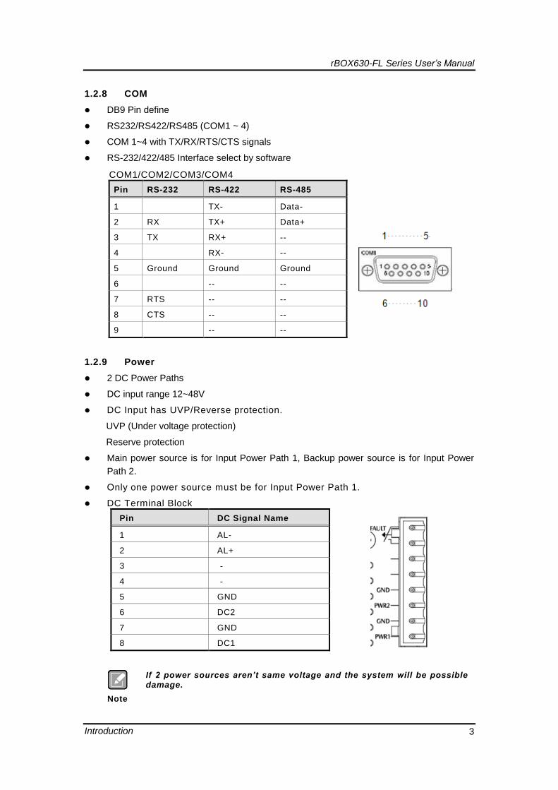
1.2.8 COM
DB9 Pin define
RS232/RS422/RS485 (COM1 ~ 4)
COM 1~4 with TX/RX/RTS/CTS signals
RS-232/422/485 Interface select by software
COM1/COM2/COM3/COM4
Pin RS-232 RS-422 RS-485
1 TX- Data-
2 RX TX+ Data+
3 TX RX+ --
4 RX- --
5 Ground Ground Ground
6 -- --
7 RTS -- --
8 CTS -- --
9 -- --
1.2.9 Power
2 DC Power Paths
DC input range 12~48V
DC Input has UVP/Reverse protection.
UVP (Under voltage protection)
Reserve protection
Main power source is for Input Power Path 1, Backup power source is for Input Power
Path 2.
Only one power source must be for Input Power Path 1.
DC Terminal Block
Pin DC Signal Name
1 AL-
2 AL+
3 -
4 -
5 GND
6 DC2
7 GND
8 DC1
Note
If 2 power sources aren’t same voltage and the system will be possible damage.
rBOX630-FL Series User’s Manual
Introduction 4
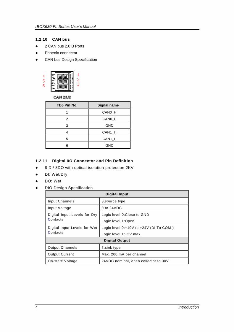
1.2.10 CAN bus
2 CAN bus 2.0 B Ports
Phoenix connector
CAN bus Design Specification
TB6 Pin No. Signal name
1 CAN0_H
2 CAN0_L
3 GND
4 CAN1_H
5 CAN1_L
6 GND
1.2.11 Digital I/O Connector and Pin Definition
8 DI/ 8DO with optical isolation protection 2KV
DI: Wet/Dry
DO: Wet
DIO Design Specification
Digital Input
Input Channels 8,source type
Input Voltage 0 to 24VDC
Digital Input Levels for Dry
Contacts
Logic level 0:Close to GND
Logic level 1:Open
Digital Input Levels for Wet
Contacts
Logic level 0:+10V to +24V (DI To COM-)
Logic level 1:+3V max.
Digital Output
Output Channels 8,sink type
Output Current Max. 200 mA per channel
On-state Voltage 24VDC nominal, open collector to 30V
rBOX630-FL Series User’s Manual
Introduction 5
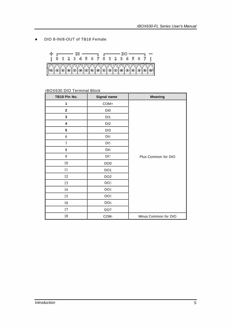
DIO 8-IN/8-OUT of TB18 Female
rBOX630 DIO Terminal Block
TB18 Pin No. Signal name Meaning
1 COM+
Plus Common for DIO
2 DI0
3 DI1
4 DI2
5 DI3
6 DI4
7 DI5
8 DI6
9 DI7
10 DO0
11 DO1
12 DO2
13 DO3
14 DO4
15 DO5
16 DO6
17 DO7
18 COM- Minus Common for DIO
rBOX630-FL Series User’s Manual
Introduction 6
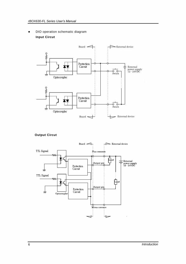
DIO operation schematic diagram
Input Circut
Output Circut
rBOX630-FL Series User’s Manual
Introduction 7
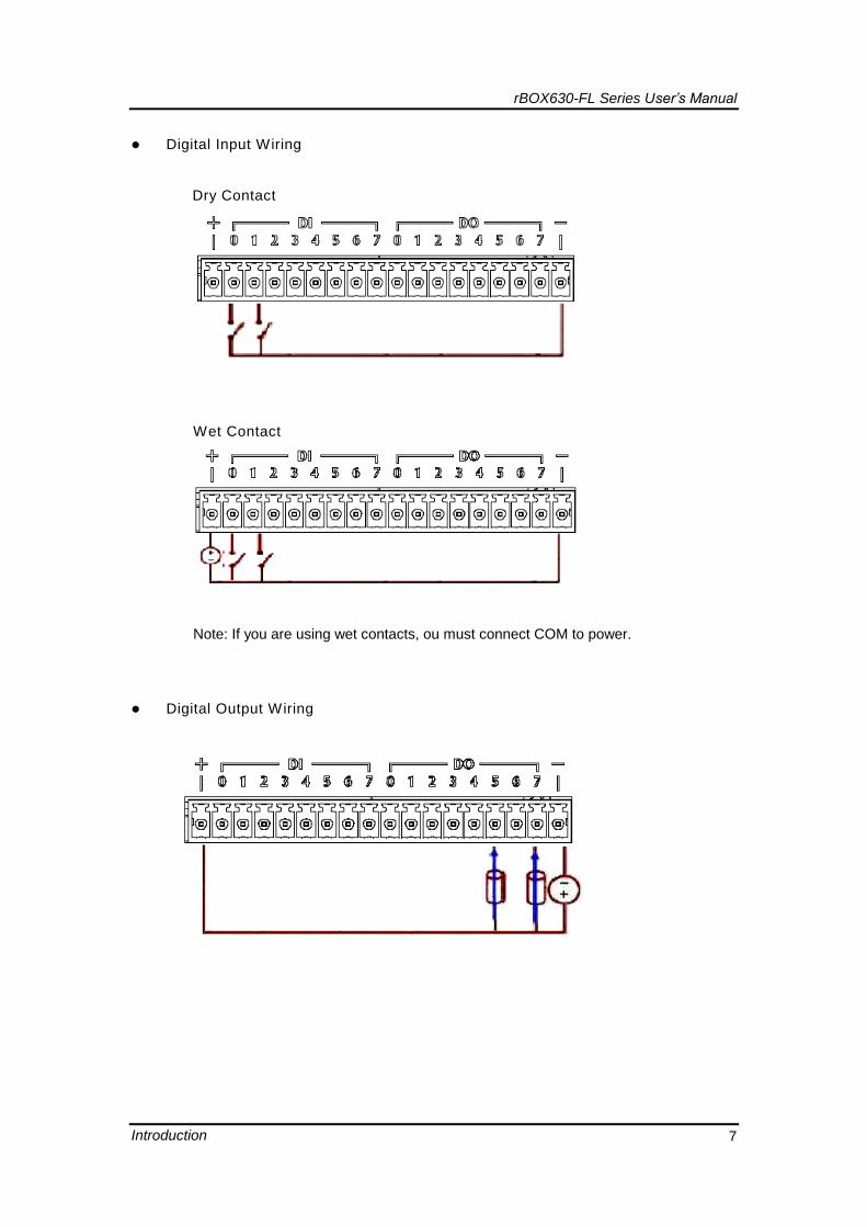
Digital Input Wiring
Dry Contact
Wet Contact
Note: If you are using wet contacts, ou must connect COM to power.
Digital Output Wiring
rBOX630-FL Series User’s Manual
Introduction 8
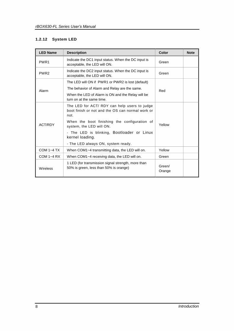
1.2.12 System LED
LED Name Description Color Note
PWR1 Indicate the DC1 input status. When the DC input is
acceptable, the LED will ON. Green
PWR2 Indicate the DC2 input status. When the DC input is
acceptable, the LED will ON. Green
Alarm
The LED will ON if PWR1 or PWR2 is lost (default)
The behavior of Alarm and Relay are the same.
When the LED of Alarm is ON and the Relay will be
turn on at the same time.
Red
ACT/RDY
The LED for ACT/ RDY can help users to judge
boot finish or not and the OS can normal work or
not.
When the boot finishing the configuration of
system, the LED will ON.
- The LED is blinking, Bootloader or Linux
kernel loading.
- The LED always ON, system ready.
Yellow
COM 1~4 TX When COM1~4 transmitting data, the LED will on. Yellow
COM 1~4 RX When COM1~4 receiving data, the LED will on. Green
Wireless
1 LED (for transmission signal strength, more than
50% is green, less than 50% is orange)
Green/
Orange
rBOX630-FL Series User’s Manual
Introduction 9
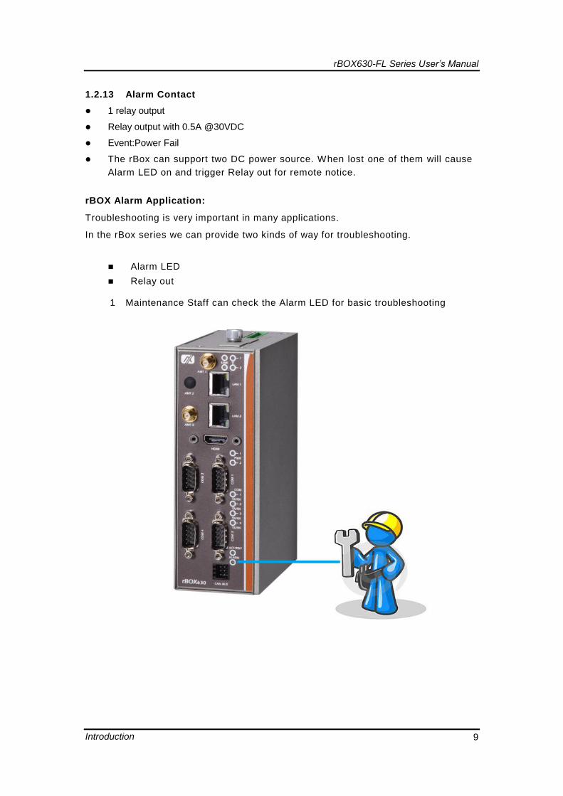
1.2.13 Alarm Contact
1 relay output
Relay output with 0.5A @30VDC
Event:Power Fail
The rBox can support two DC power source. When lost one of them will cause
Alarm LED on and trigger Relay out for remote notice.
rBOX Alarm Application:
Troubleshooting is very important in many applications.
In the rBox series we can provide two kinds of way for troubleshooting.
Alarm LED
Relay out
1 Maintenance Staff can check the Alarm LED for basic troubleshooting
rBOX630-FL Series User’s Manual
Introduction 10
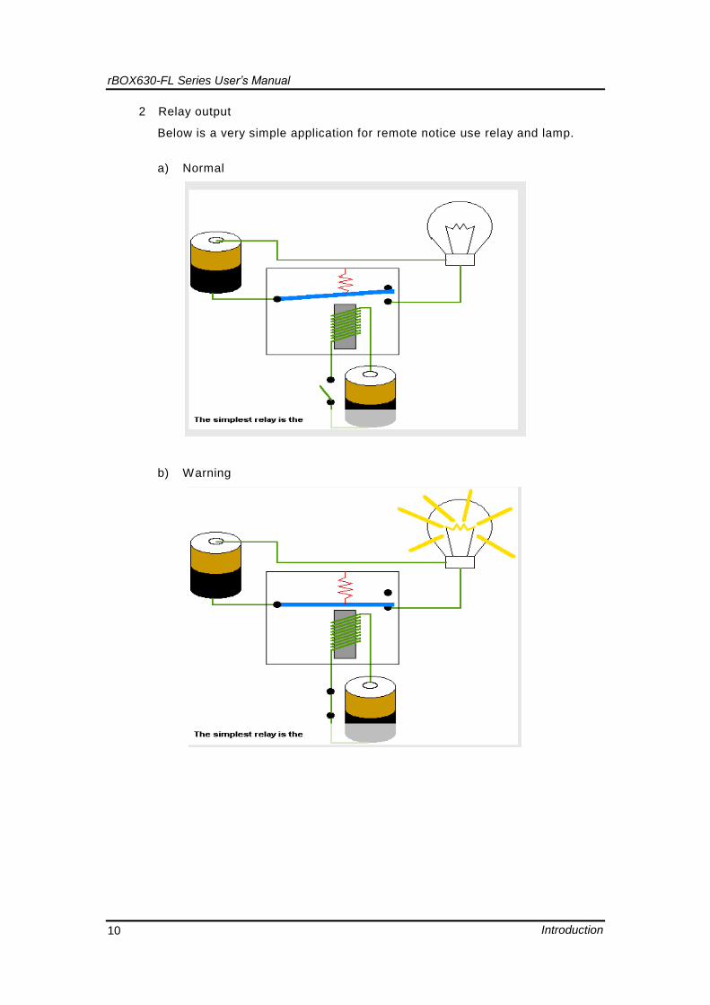
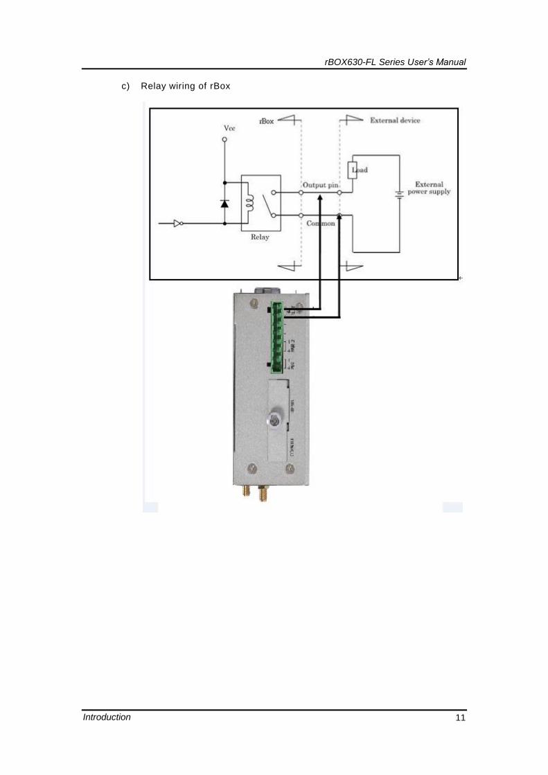
2 Relay output
Below is a very simple application for remote notice use relay and lamp.
a) Normal
b) Warning
rBOX630-FL Series User’s Manual
Introduction 11
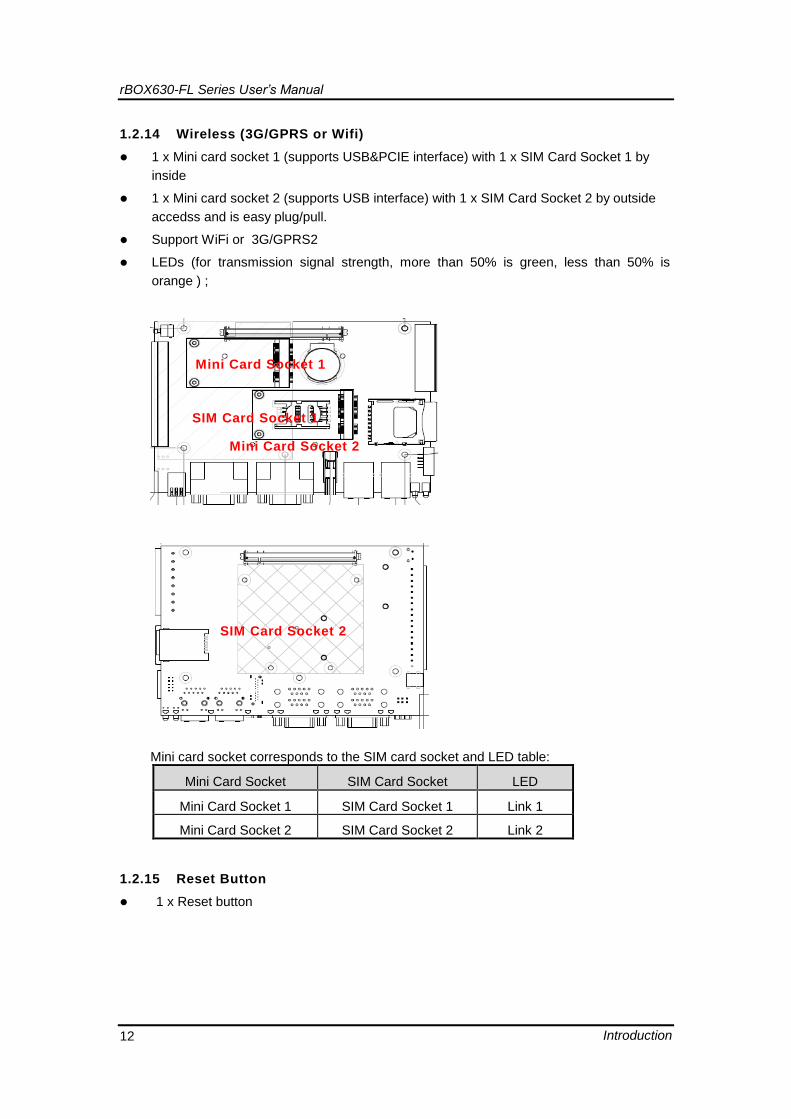
c) Relay wiring of rBox
rBOX630-FL Series User’s Manual
Introduction 12
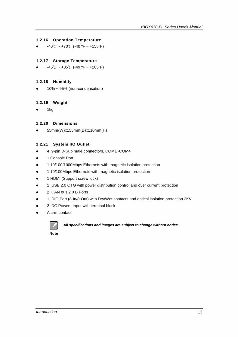
1.2.14 Wireless (3G/GPRS or Wifi)
1 x Mini card socket 1 (supports USB&PCIE interface) with 1 x SIM Card Socket 1 by
inside
1 x Mini card socket 2 (supports USB interface) with 1 x SIM Card Socket 2 by outside
accedss and is easy plug/pull.
Support WiFi or 3G/GPRS2
LEDs (for transmission signal strength, more than 50% is green, less than 50% is
orange ) ;
Sim card compatible with mini card table
Mini card socket corresponds to the SIM card socket and LED table:
Mini Card Socket SIM Card Socket LED
Mini Card Socket 1 SIM Card Socket 1 Link 1
Mini Card Socket 2 SIM Card Socket 2 Link 2
1.2.15 Reset Button
1 x Reset button
Mini Card Socket 1
Mini Card Socket 2
SIM Card Socket 1
SIM Card Socket 2
rBOX630-FL Series User’s Manual
Introduction 13
1.2.16 Operation Temperature
-40℃ ~ +70℃ (-40 ºF ~ +158ºF)
1.2.17 Storage Temperature
-45℃ ~ +85℃ (-49 ºF ~ +185ºF)
1.2.18 Humidity
10% ~ 95% (non-condensation)
1.2.19 Weight
1kg
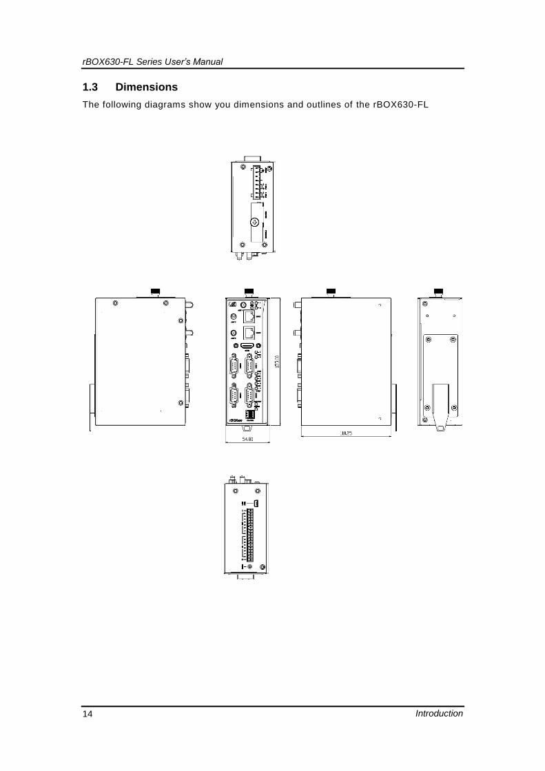
1.2.20 Dimensions
55mm(W)x155mm(D)x110mm(H)
1.2.21 System I/O Outlet
4 9-pin D-Sub male connectors, COM1~COM4
1 Console Port
1 10/100/1000Mbps Ethernets with magnetic isolation protection
1 10/100Mbps Ethernets with magnetic isolation protection
1 HDMI (Support screw lock)
1 USB 2.0 OTG with power distribution control and over current protection
2 CAN bus 2.0 B Ports
1 DIO Port (8-In/8-Out) with Dry/Wet contacts and optical isolation protection 2KV
2 DC Powers Input with terminal block
Alarm contact
Note
All specifications and images are subject to change without notice.
rBOX630-FL Series User’s Manual
Introduction 14
1.3 Dimensions
The following diagrams show you dimensions and outlines of the rBOX630-FL
rBOX630-FL Series User’s Manual
Introduction 15
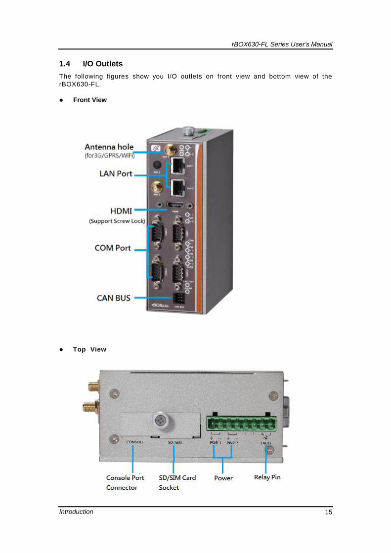
1.4 I/O Outlets
The following figures show you I/O outlets on front view and bottom view of the
rBOX630-FL.
Front View
Top View
rBOX630-FL Series User’s Manual
Introduction 16
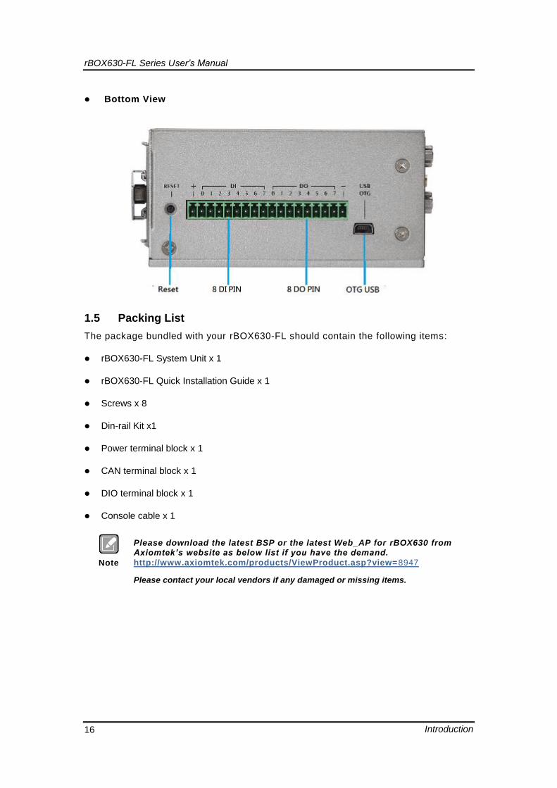
Bottom View
1.5 Packing List
The package bundled with your rBOX630-FL should contain the following items:
rBOX630-FL System Unit x 1
rBOX630-FL Quick Installation Guide x 1
Screws x 8
Din-rail Kit x1
Power terminal block x 1
CAN terminal block x 1
DIO terminal block x 1
Console cable x 1
Note
Please download the latest BSP or the latest Web_AP for rBOX630 from Axiomtek’s website as below list if you have the demand.
http://www.axiomtek.com/products/ViewProduct.asp?view=8947
Please contact your local vendors if any damaged or missing items.
rBOX630-FL Series User’s Manual
Hardware Installation 17
CHAPTER 2
HARDWARE INSTALLATION
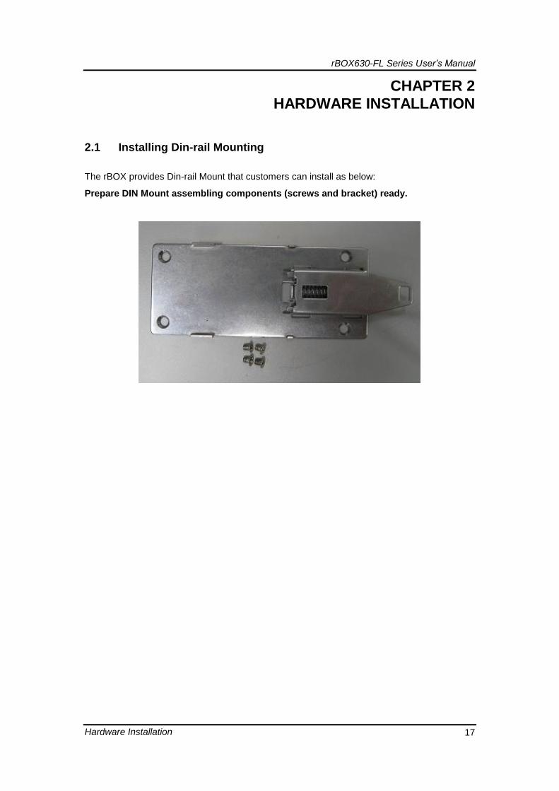
2.1 Installing Din-rail Mounting
The rBOX provides Din-rail Mount that customers can install as below:
Prepare DIN Mount assembling components (screws and bracket) ready.

rBOX630-FL Series User’s Manual
Hardware Installation 18
This page is intentionally left blank.