Embed Size (px)
Citation preview

1
Contents
1. Overview............................................................................................................................4
2. References.........................................................................................................................5
3. Package.............................................................................................................................6
3.1 Box......................................................................................................................................... 6
4. Complete package contents..............................................................................................7
5. General presentation.........................................................................................................8
5.1 Product pictures ....................................................................................................................8
5.2 External connections..............................................................................................................9
5.2.1 Antenna connector...........................................................................................................9
5.2.2 Memory slot.....................................................................................................................9
5.2.3 USB Interface................................................................................................................10
5.2.4 RS-232 Interface (EIA574)............................................................................................10
5.2.5 D-Sub HD 15-pin connector...........................................................................................11
5.2.6 Power supply connector................................................................................................12
5.2.7 SIM card holder.............................................................................................................13
5.3 Product sticker....................................................................................................................13
6. Basic features and services.............................................................................................14
7. Using the modem.............................................................................................................15
7.1 Setting up the modem...........................................................................................................15
7.2 Mounting the modem...........................................................................................................16
7.2.1 On DIN bus....................................................................................................................16
7.2.2 On the wall.....................................................................................................................17
7.3 Checking the communication with the modem.....................................................................17
7.4 Status of the modem (LEDs)................................................................................................18
7.5 Disabling and enabling echo function...................................................................................18
7.6 Verifying the strength of received signal...............................................................................19
7.7 PIN code status...................................................................................................................19
7.8 Network registration..............................................................................................................20
7.8.1 GSM network registration..............................................................................................20
7.9 GPRS network registration...................................................................................................21
7.10 AT commands summary.....................................................................................................22
8. Troubleshooting................................................................................................................23
8.1 No connection/communication with the modem....................................................................23
8.2 Receiving ERROR message................................................................................................23
2
8.3 Receiving NO CARRIER message.......................................................................................24
9. Technical characteristics..................................................................................................25
9.1 Mechanical characteristic.....................................................................................................25
9.2 Housing description (dimensioning diagram)........................................................................25
10. Electrical characteristic..................................................................................................26
10.1 Power supply......................................................................................................................26
10.2 RF characteristics...............................................................................................................26
10.3 External antenna................................................................................................................27
10.4 Environmental characteristic...............................................................................................27
11. Python Script Interpreter................................................................................................28
12. AT Reference manual.....................................................................................................30
13. Safety recommendations...............................................................................................43
13.1 General Safety....................................................................................................................43
13.2 Care and Maintenance.......................................................................................................43
13.3 Responsibility.....................................................................................................................43
14. Accessories....................................................................................................................44
14.1 Accessories critical for using modem..................................................................................44
14.2 Additional accessories........................................................................................................45
15. Conformity Assessment Issues......................................................................................46
16. Safety Recommendations..............................................................................................47
17. List of Acronyms.............................................................................................................48
18. On-line support...............................................................................................................50
3
1. Overview
The RB800 Terminal is the complete modem solution for wireless m2m applications. Based on the Telit GL865 or UL865 module, it is available as quad or dual-band version and offers high level GSM/GPRS/UMTS features in compact aluminium housing with all the standardized interfaces. Together with its small size and wide supply voltage range, makes it easy to integrate into all kinds of machines.
The RB800 terminal enabling voice, high speed data transmission, SMS and fax communication is a universal solution for all low-volume M2M and mobile data applications including metering, traffic systems, transportation and logistics, security, vending machines, and facility management.
Device can be controlled by standard AT commands or by customer's application inside (embedded Python Script Interpreter), thus making it the smallest, complete SMT platform for m2m solutions.
This document contains full RB800 modem description and gives information about installation and using it.
4
2. References
[1] Telit_AT_Commands_Reference_Guide.pdf
[2] Telit_HE910_UE910_UL865_AT_Commands_Reference_Guide.pdf
[3] Telit_GL865-DUAL_QUAD_Product_Description.pdf
[4] Telit_UL865_Product_Description.pdf
[5] Telit_Easy_Script_Python_1.5.2.pdf
[6] Telit_Easy_Script_Python_2.7.pdf
[7] http://www.telit.com/en/products/umts.php?p_id=14&p_ac=show&p=145
[8] http://www.python.org/
5
3. Package
3.1 Box
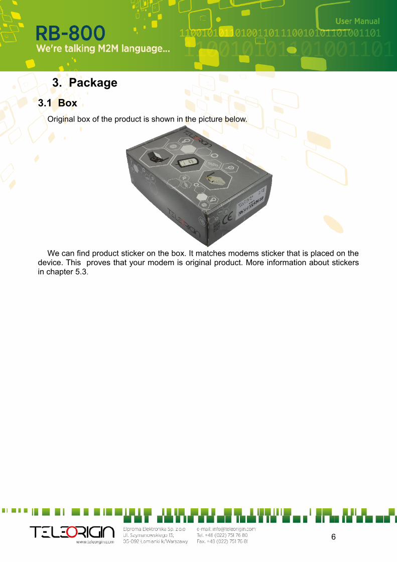
Original box of the product is shown in the picture below.
We can find product sticker on the box. It matches modems sticker that is placed on the device. This proves that your modem is original product. More information about stickers in chapter 5.3.
6
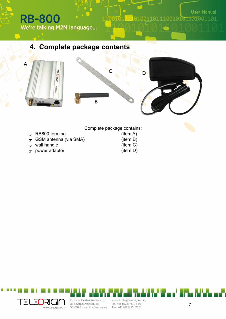
4. Complete package contents
Complete package contains: RB800 terminal (item A) GSM antenna (via SMA) (item B) wall handle (item C) power adaptor (item D)
7
5. General presentation
5.1 Product pictures
8
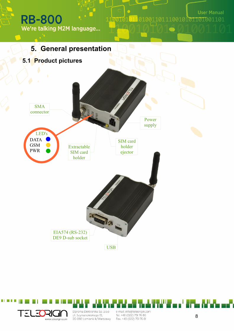
SMA connector
Extractable SIM card
holder
SIM card holder ejector
Power supply
EIA574 (RS-232) DE9 D-sub socket
USB
DATAGSMPWR
LED's
5.2 External connections
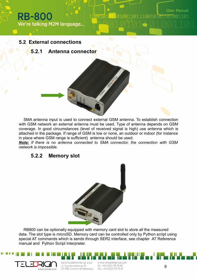
5.2.1 Antenna connector
SMA antenna input is used to connect external GSM antenna. To establish connection with GSM network an external antenna must be used. Type of antenna depends on GSM coverage. In good circumstances (level of received signal is high) use antenna which is attached in the package. If range of GSM is low or none, an outdoor or indoor (for instance in place where GSM range is sufficient) antenna should be used.Note: If there is no antenna connected to SMA connector, the connection with GSM network is impossible.
5.2.2 Memory slot
RB800 can be optionally equipped with memory card slot to store all the measured data. The slot type is microSD. Memory card can be controlled only by Python script using special AT commands which is sends through SER2 interface, see chapter AT Reference manual and Python Script Interpreter.
9
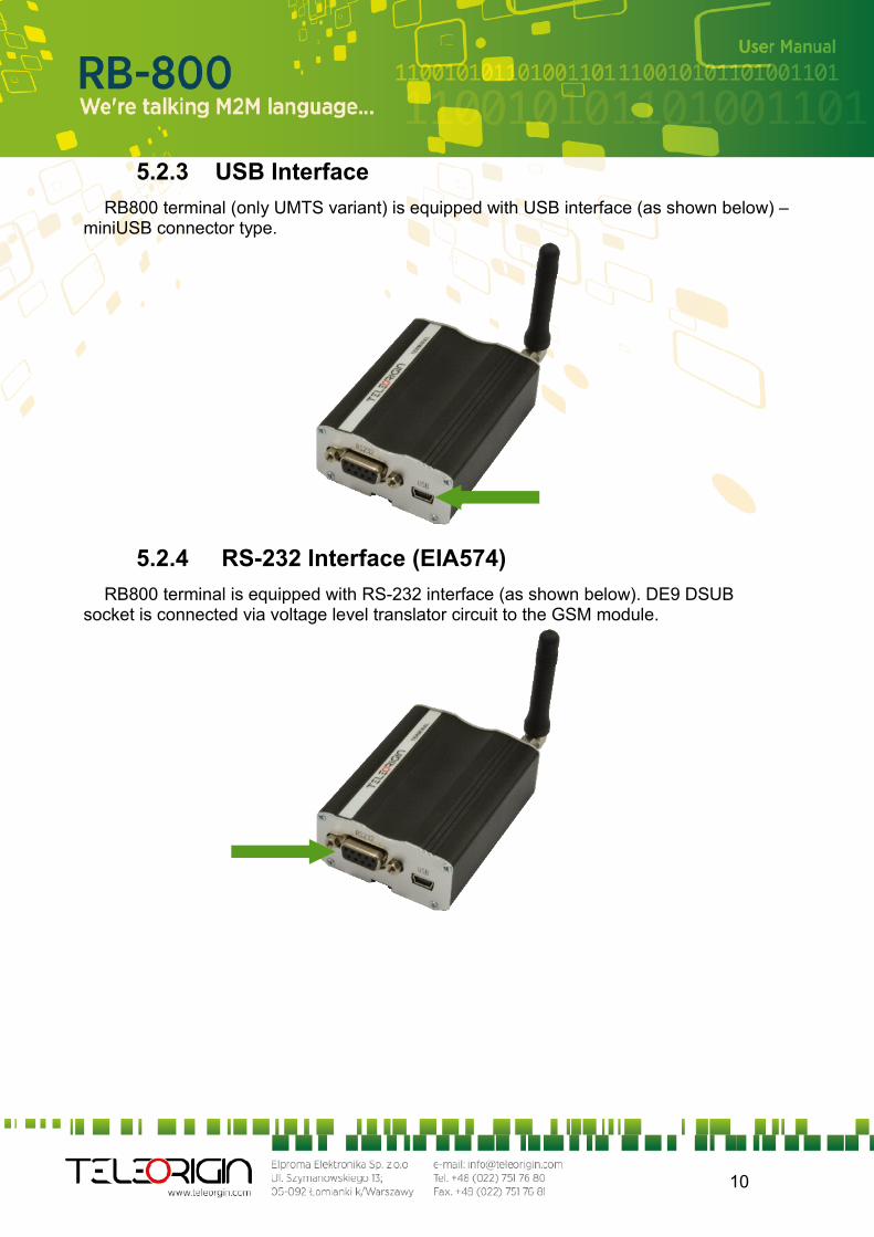
5.2.3 USB Interface
RB800 terminal (only UMTS variant) is equipped with USB interface (as shown below) – miniUSB connector type.
5.2.4 RS-232 Interface (EIA574)
RB800 terminal is equipped with RS-232 interface (as shown below). DE9 DSUBsocket is connected via voltage level translator circuit to the GSM module.
10
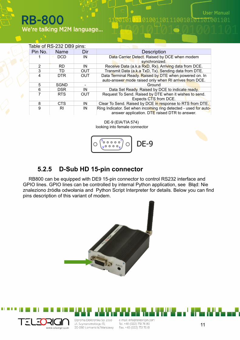
Table of RS-232 DB9 pins:Pin No. Name Dir Description
1 DCD IN Data Carrier Detect. Raised by DCE when modem synchronized.
2 RD IN Receive Data (a.k.a RxD, Rx). Arriving data from DCE.3 TD OUT Transmit Data (a.k.a TxD, Tx). Sending data from DTE.4 DTR OUT Data Terminal Ready. Raised by DTE when powered on. In
auto-answer mode raised only when RI arrives from DCE.5 SGND - Ground6 DSR IN Data Set Ready. Raised by DCE to indicate ready.7 RTS OUT Request To Send. Raised by DTE when it wishes to send.
Expects CTS from DCE.8 CTS IN Clear To Send. Raised by DCE in response to RTS from DTE.9 RI IN Ring Indicator. Set when incoming ring detected - used for auto-
answer application. DTE raised DTR to answer.
DE-9 (EIA/TIA 574) looking into female connector
5.2.5 D-Sub HD 15-pin connector
RB800 can be equipped with DE9 15-pin connector to control RS232 interface and GPIO lines. GPIO lines can be controlled by internal Python application, see Błąd: Nie znaleziono źródła odwołania and Python Script Interpreter for details. Below you can find pins description of this variant of modem.
11
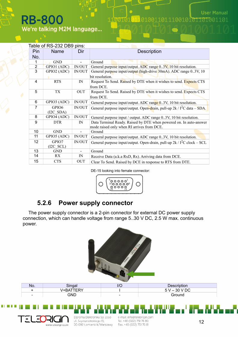
Table of RS-232 DB9 pins:Pin No.
Name Dir Description
1 GND - Ground 2 GPIO1 (ADC) IN/OUT General purpose input/output. ADC range 0..3V, 10 bit resolution. 3 GPIO2 (ADC) IN/OUT General purpose input/output (high-drive 30mA). ADC range 0..3V, 10
bit resolution. 4 RTS IN Request To Send. Raised by DTE when it wishes to send. Expects CTS
from DCE. 5 TX OUT Request To Send. Raised by DTE when it wishes to send. Expects CTS
from DCE. 6 GPIO3 (ADC) IN/OUT General purpose input/output. ADC range 0..3V, 10 bit resolution. 7 GPIO6
(I2C_SDA) IN/OUT General purpose input/output. Open-drain, pull-up 2k / I2C data – SDA.
8 GPIO4 (ADC) IN/OUT General purpose input / output. ADC range 0..3V, 10 bit resolution. 9 DTR IN Data Terminal Ready. Raised by DTE when powered on. In auto-answer
mode raised only when RI arrives from DCE.10 GND - Ground 11 GPIO5 (ADC) IN/OUT General purpose input/output. ADC range 0..3V, 10 bit resolution. 12 GPIO7
(I2C_SCL) IN/OUT General purpose input/output. Open-drain, pull-up 2k / I2C clock – SCL
13 GND - Ground 14 RX IN Receive Data (a.k.a RxD, Rx). Arriving data from DCE. 15 CTS OUT Clear To Send. Raised by DCE in response to RTS from DTE.
DE-15 looking into female connector:
5.2.6 Power supply connector
The power supply connector is a 2-pin connector for external DC power supply connection, which can handle voltage from range 5..30 V DC, 2.5 W max. continuous power.
No. Singal I/O Description+ V+BATTERY I 5 V – 30 V DC- GND - Ground
12
Attention!An attempt to power terminal from DC source outside of 5..30 V range may result in physical destruction of the device.
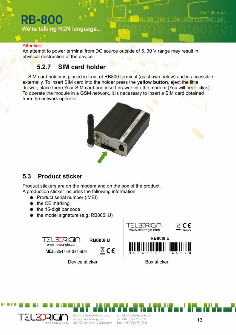
5.2.7 SIM card holder
SIM card holder is placed in front of RB800 terminal (as shown below) and is accessible externally. To insert SIM card into the holder press the yellow button, eject the little drawer, place there Your SIM card and insert drawer into the modem (You will hear click). To operate the module in a GSM network, it is necessary to insert a SIM card obtained from the network operator.
5.3 Product sticker
Product stickers are on the modem and on the box of the product.A production sticker includes the following information:
● Product serial number (IMEI)● the CE marking● the 15-digit bar code● the model signature (e.g. RB865i U)
Device sticker Box sticker
13

6. Basic features and services
Basic features and available services for RB800 are contained in table below.Feature/service Description
Standard Supported Bands:UMTS variant:
UMTS/HSPA 900/2100 Mhz (EUR/EUD version) UMTS/HSPA 850/1900 Mhz (NAR/NAD version) GSM/GPRS/EDGE 900/1800 MHz (EUR/EUD version) GSM/GPRS/EDGE 850/1900 MHz (NAR/NAD version)
GPRS variant: GSM/GPRS 850/900/1800/1900 Mhz
Physical: 83 x 53,5 x 25 mm Weight 151 g
Speed UMTS variant: HSDPA class 8 up to 7.2 Mbps HSUPA class 6 up to 5.76 Mbps WCDMA up to 384kbps downlink/uplink EDGE class 33 for EUx variants and class 10 for NAx variants GPRS class 33 for EUx variants and class 10 for NAx variants CSD up to 9.6 kbps DTM (Dual Transfer Mode)
Interfaces Connectors SMA antenna
SIM Card 3.0V / 1.8V STK 3.1
Connectivity USB 2.0 HS (UMTS variant) UART: BR from 300 bps to 115.2 Kbps Auto BR SPI
SMS MO / MT Text and PDU mode Cell broadcast SMS over GPRS
Audio DVI (UMTS variant) or standard (GPRS variant) eCall DTMF
GSM supplementary services
USSD phase II Call forwarding
Call barring Call hold & call waiting CLIP CLIR Advice of charge
Power supply 5V – 30V DC
14
7. Using the modem
7.1 Setting up the modem
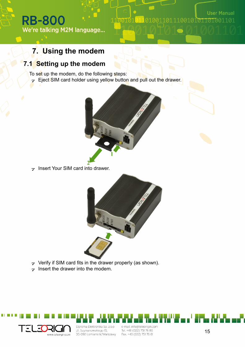
To set up the modem, do the following steps: Eject SIM card holder using yellow button and pull out the drawer.
Insert Your SIM card into drawer.
Verify if SIM card fits in the drawer properly (as shown). Insert the drawer into the modem.
15
1
2
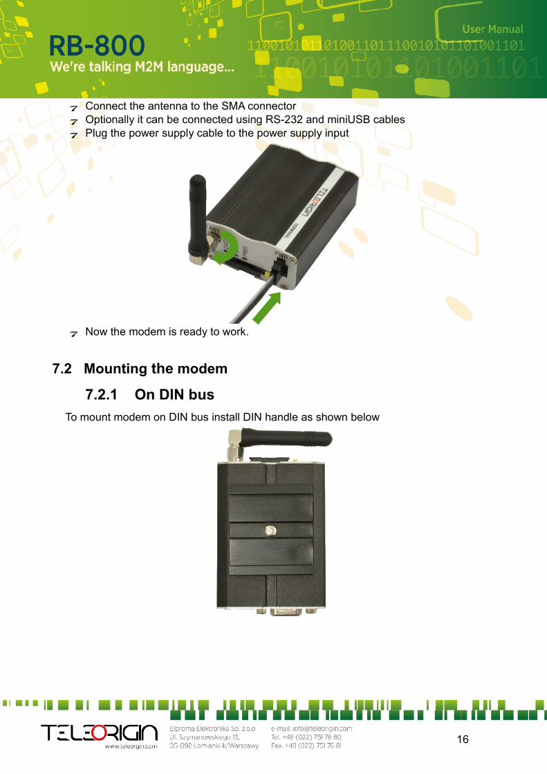
Connect the antenna to the SMA connector Optionally it can be connected using RS-232 and miniUSB cables Plug the power supply cable to the power supply input
Now the modem is ready to work.
7.2 Mounting the modem
7.2.1 On DIN bus
To mount modem on DIN bus install DIN handle as shown below
16
7.2.2 On the wall
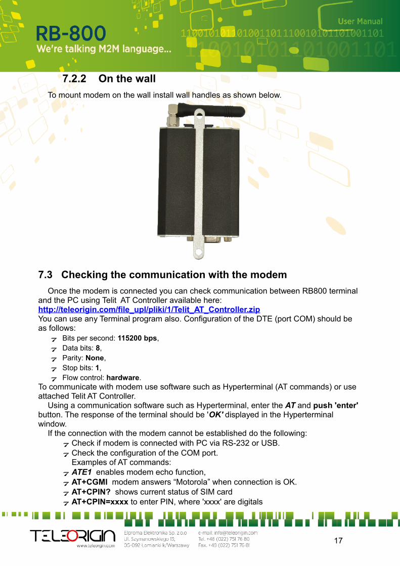
To mount modem on the wall install wall handles as shown below.
7.3 Checking the communication with the modem
Once the modem is connected you can check communication between RB800 terminal and the PC using Telit AT Controller available here: http://teleorigin.com/file_upl/pliki/1/Telit_AT_Controller.zipYou can use any Terminal program also. Configuration of the DTE (port COM) should be as follows: Bits per second: 115200 bps, Data bits: 8, Parity: None, Stop bits: 1, Flow control: hardware.
To communicate with modem use software such as Hyperterminal (AT commands) or use attached Telit AT Controller.
Using a communication software such as Hyperterminal, enter the AT and push 'enter' button. The response of the terminal should be 'OK' displayed in the Hyperterminal window.
If the connection with the modem cannot be established do the following: Check if modem is connected with PC via RS-232 or USB. Check the configuration of the COM port.
Examples of AT commands: ATE1 enables modem echo function, AT+CGMI modem answers “Motorola” when connection is OK. AT+CPIN? shows current status of SIM card AT+CPIN=xxxx to enter PIN, where 'xxxx' are digitals
17

AT+CSQ to verify received signal strength ATD<phone_number>; to initiate a voice call ATH to hang up a voice call
For further information about AT commands and their usage, refer to [1].
7.4 Status of the modem (LEDs)
The operational status of the RB800 Terminal is signalized by external LEDs placed on the front panel of the modem.
The table below shows what is the meaning of LEDs.LED
nameLED colour Description
DATA blue Software controlled:In GPRS modem variant: AT#GPIO=5,1,1 – diode ON, AT#GPIO=5,0,1 – diode OFFIn UMTS modem variant: AT#GPIO=5,0,1 – diode ON, AT#GPIO=5,1,1 – diode OFF
GSM orange Software controlled using AT#SLED (GPRS modem variant) or AT#GPIO=8 and AT#SLED (UMTS modem variant):Blinking every second – modem is not logged on to GSM networkBlinking every 3 seconds – modem is logged on to GSM network.
PWR green Lights when modem is power on
7.5 Disabling and enabling echo function
If echo is not displayed when entering AT command, that means: The local echo function in software (such as Hyperterminal) is disabled The echo function of the modem is disabled
To enable echo function of the modem enter ATE1 command.
In Machine to Machine communication it is recommended to disable echo function (type ATE0) in order to avoid useless CPU processing.
For further information about AT commands and their usage, refer to [1].
18
7.6 Verifying the strength of received signal
RB800 terminal can establish connection with network if the received signal strength is sufficiently strong.
To verify the signal strength and bit error rate, do the following:Using software such as Hyperterminal enter AT+CSQ. This command displays the
received signal strength indication <rssi> and channel bit error rate <ber>. The modem answers as follows:
+CSQ: <rssi>,<ber>OK
<parameter> Description<rssi> 0 through 31 - covers the range of -113 dbm (or less) to -51dbm (or greater)<ber> Channel bit error rate (in percent)
0–7 RXQUAL values in the GSM 05.08 table99 Unknown or not detectable
For further information about AT commands and their usage, refer to [1].
7.7 PIN code status
To check PIN code status enter AT+CPIN? Command.The table below shows the most interesting responses of the modem:
Answer Description+CPIN: SIM PIN PIN code has not been entered+CPIN: READY PIN code has been entered correctly
For further information about AT commands and their usage, refer to [1].
19
7.8 Network registration
7.8.1 GSM network registration
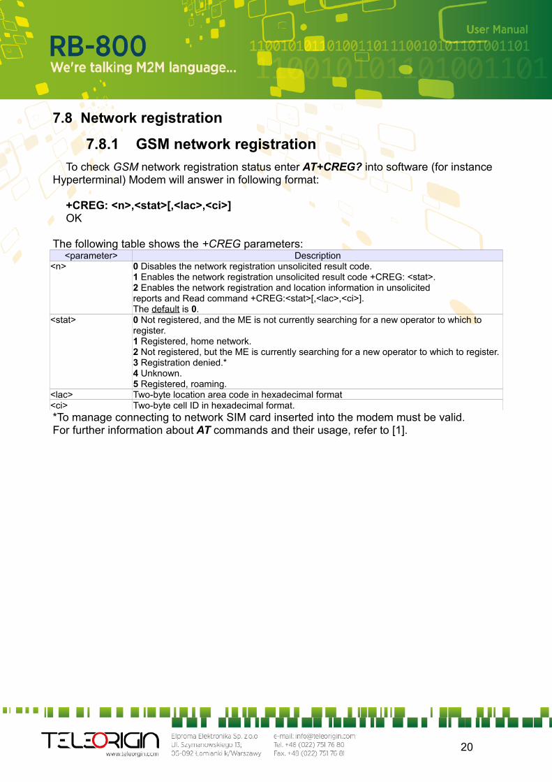
To check GSM network registration status enter AT+CREG? into software (for instance Hyperterminal) Modem will answer in following format:
+CREG: <n>,<stat>[,<lac>,<ci>]OK
The following table shows the +CREG parameters:<parameter> Description
<n> 0 Disables the network registration unsolicited result code.1 Enables the network registration unsolicited result code +CREG: <stat>.2 Enables the network registration and location information in unsolicitedreports and Read command +CREG:<stat>[,<lac>,<ci>].The default is 0.
<stat> 0 Not registered, and the ME is not currently searching for a new operator to which to register.1 Registered, home network.2 Not registered, but the ME is currently searching for a new operator to which to register.3 Registration denied.*4 Unknown.5 Registered, roaming.
<lac> Two-byte location area code in hexadecimal format<ci> Two-byte cell ID in hexadecimal format.*To manage connecting to network SIM card inserted into the modem must be valid.For further information about AT commands and their usage, refer to [1].
20
7.9 GPRS network registration
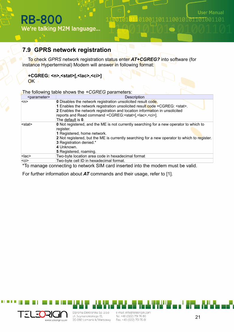
To check GPRS network registration status enter AT+CGREG? into software (for instance Hyperterminal) Modem will answer in following format:
+CGREG: <n>,<stat>[,<lac>,<ci>]OK
The following table shows the +CGREG parameters:<parameter> Description
<n> 0 Disables the network registration unsolicited result code.1 Enables the network registration unsolicited result code +CGREG: <stat>.2 Enables the network registration and location information in unsolicitedreports and Read command +CGREG:<stat>[,<lac>,<ci>].The default is 0.
<stat> 0 Not registered, and the ME is not currently searching for a new operator to which to register.1 Registered, home network.2 Not registered, but the ME is currently searching for a new operator to which to register.3 Registration denied.*4 Unknown.5 Registered, roaming.
<lac> Two-byte location area code in hexadecimal format<ci> Two-byte cell ID in hexadecimal format.*To manage connecting to network SIM card inserted into the modem must be valid.
For further information about AT commands and their usage, refer to [1].
21
7.10 AT commands summary
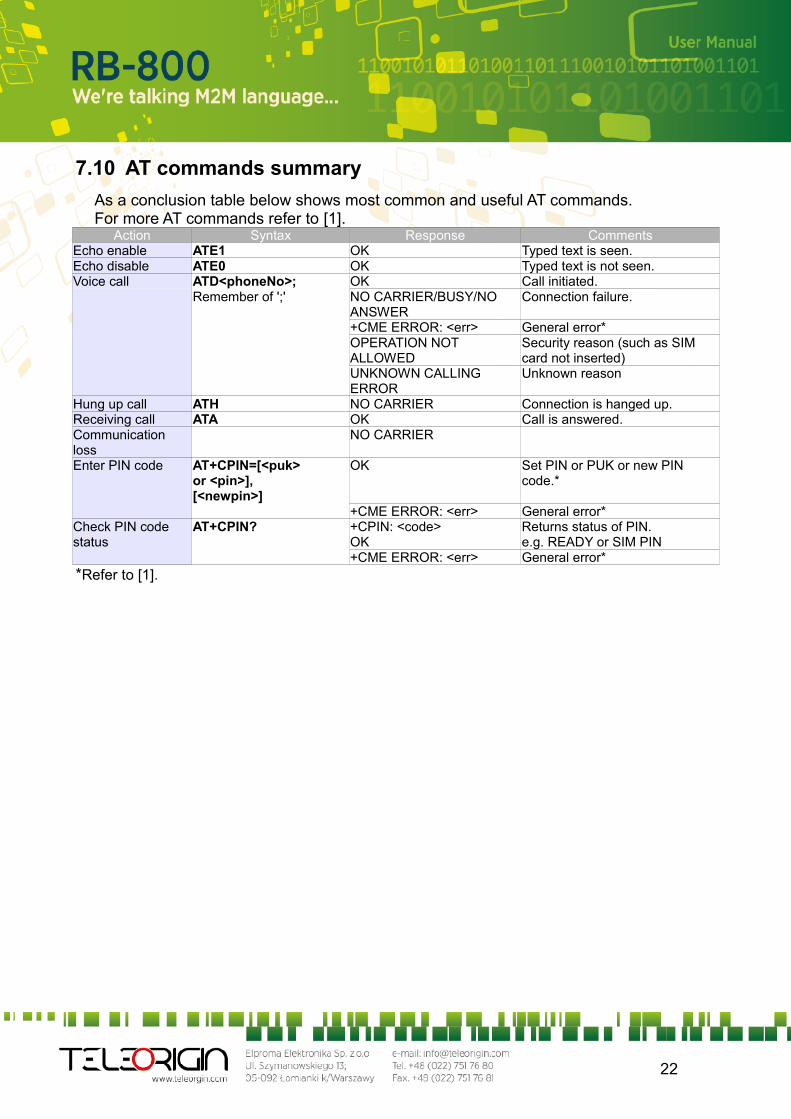
As a conclusion table below shows most common and useful AT commands.For more AT commands refer to [1].
Action Syntax Response CommentsEcho enable ATE1 OK Typed text is seen.Echo disable ATE0 OK Typed text is not seen.Voice call ATD<phoneNo>; OK Call initiated.
Remember of ';' NO CARRIER/BUSY/NO ANSWER
Connection failure.
+CME ERROR: <err> General error*OPERATION NOT ALLOWED
Security reason (such as SIM card not inserted)
UNKNOWN CALLING ERROR
Unknown reason
Hung up call ATH NO CARRIER Connection is hanged up.Receiving call ATA OK Call is answered.Communication loss
NO CARRIER
Enter PIN code AT+CPIN=[<puk>or <pin>],[<newpin>]
OK Set PIN or PUK or new PIN code.*
+CME ERROR: <err> General error*Check PIN code status
AT+CPIN? +CPIN: <code>OK
Returns status of PIN.e.g. READY or SIM PIN
+CME ERROR: <err> General error**Refer to [1].
22
8. Troubleshooting
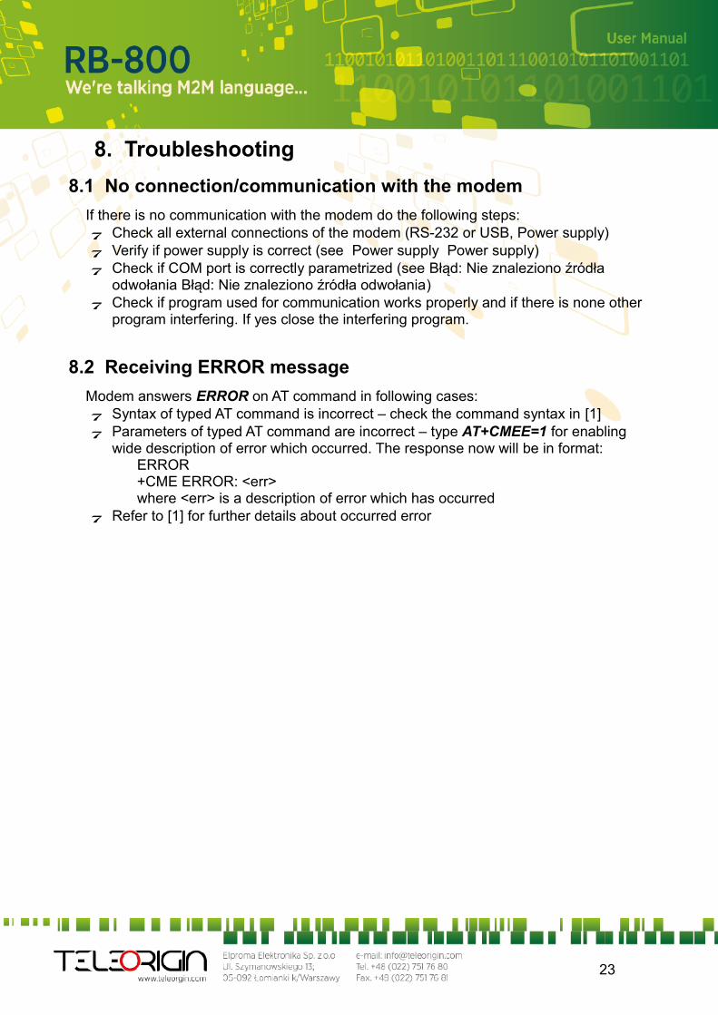
8.1 No connection/communication with the modem
If there is no communication with the modem do the following steps: Check all external connections of the modem (RS-232 or USB, Power supply) Verify if power supply is correct (see Power supply Power supply) Check if COM port is correctly parametrized (see Błąd: Nie znaleziono źródła
odwołania Błąd: Nie znaleziono źródła odwołania) Check if program used for communication works properly and if there is none other
program interfering. If yes close the interfering program.
8.2 Receiving ERROR message
Modem answers ERROR on AT command in following cases: Syntax of typed AT command is incorrect – check the command syntax in [1] Parameters of typed AT command are incorrect – type AT+CMEE=1 for enabling
wide description of error which occurred. The response now will be in format:ERROR+CME ERROR: <err>where <err> is a description of error which has occurred
Refer to [1] for further details about occurred error
23
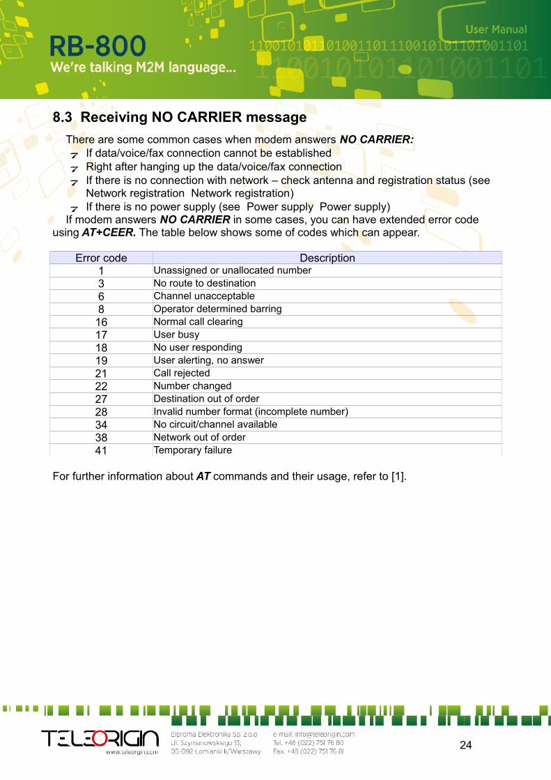
8.3 Receiving NO CARRIER message
There are some common cases when modem answers NO CARRIER: If data/voice/fax connection cannot be established Right after hanging up the data/voice/fax connection If there is no connection with network – check antenna and registration status (see
Network registration Network registration) If there is no power supply (see Power supply Power supply)
If modem answers NO CARRIER in some cases, you can have extended error code using AT+CEER. The table below shows some of codes which can appear.
Error code Description1 Unassigned or unallocated number3 No route to destination6 Channel unacceptable8 Operator determined barring16 Normal call clearing17 User busy18 No user responding19 User alerting, no answer21 Call rejected22 Number changed27 Destination out of order28 Invalid number format (incomplete number)34 No circuit/channel available38 Network out of order41 Temporary failure
For further information about AT commands and their usage, refer to [1].
24
9. Technical characteristics
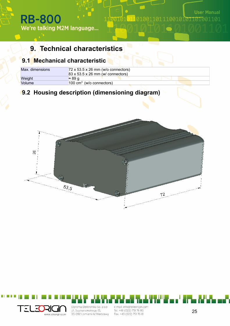
9.1 Mechanical characteristicMax. dimensions 72 x 53.5 x 26 mm (w/o connectors)
83 x 53.5 x 26 mm (w/ connectors)Weight ≈ 89 g Volume 100 cm3 (w/o connectors)
9.2 Housing description (dimensioning diagram)
25
10. Electrical characteristic
10.1 Power supply
Nominal voltage range: 5..30 V, 10% Maximum continuous (average) supply power: 2.5 W Maximum continuous (average) supply current: 200 mA at 12V, 100 mA at 24V
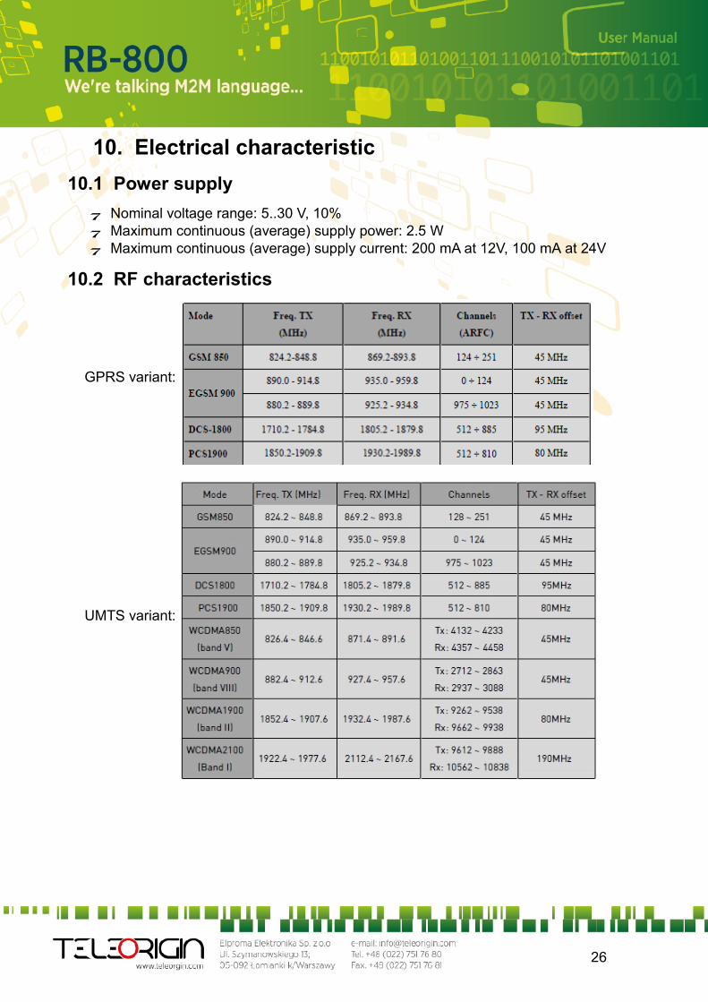
10.2 RF characteristics
GPRS variant:
UMTS variant:
26
10.3 External antenna
The external antenna is connected to the modem via SMA connector.Antenna must have parameters as shown below in table.
Antenna frequency range Quad-band GSM 850/900/1800/1900 MHz or UMTS 900/2100 Mhz
Impedance 50 ΩDC impedance 0 ΩGain 0 dBi w/o cable; 2dBi w/ cableVSWR (with cable) -10 dB
The antenna chosen for working with modem should best fit to circumstances of environment it is used in. When the modem is placed in a room or somewhere where the range of networks signal is too low, the outdoor or specific indoor antenna should be used to increase it.
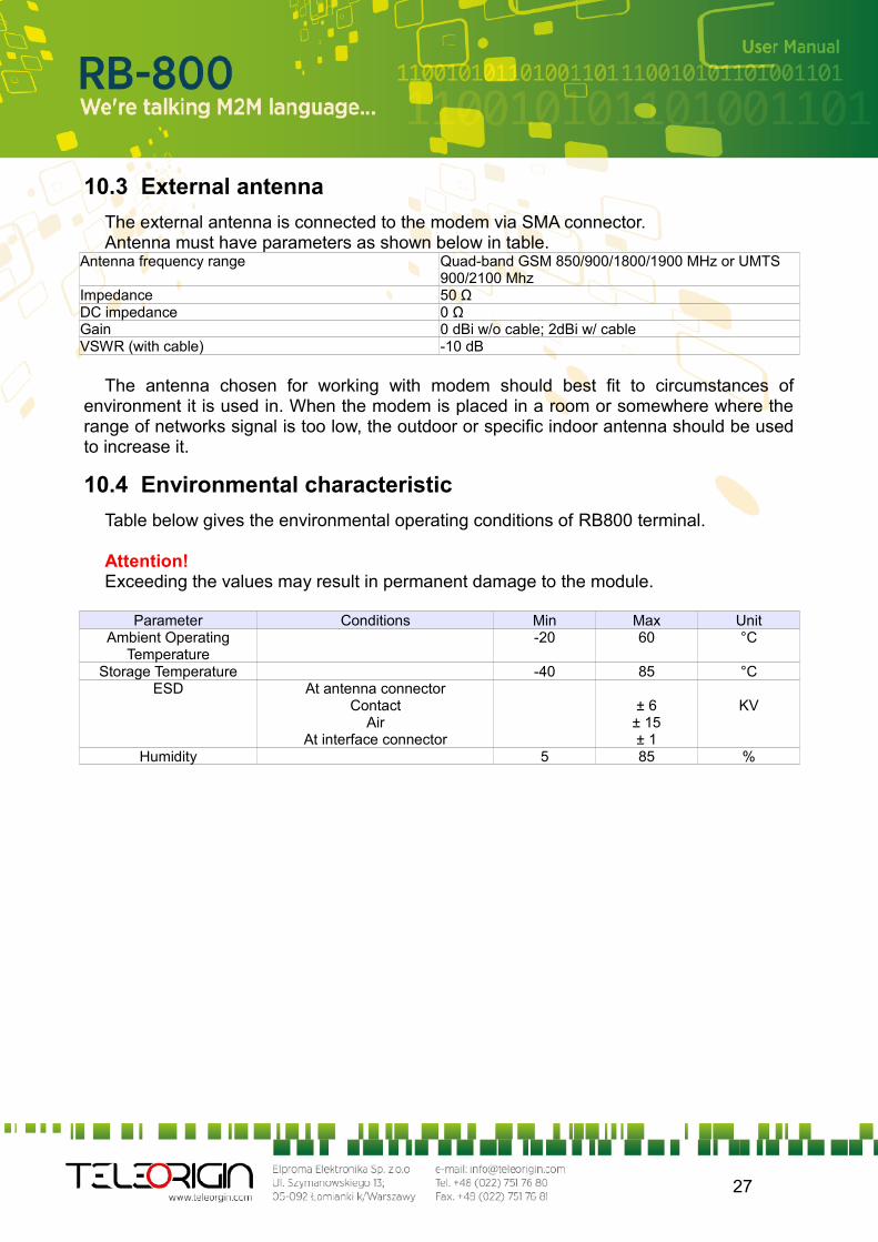
10.4 Environmental characteristic
Table below gives the environmental operating conditions of RB800 terminal.
Attention!Exceeding the values may result in permanent damage to the module.
Parameter Conditions Min Max UnitAmbient Operating
Temperature-20 60 °C
Storage Temperature -40 85 °CESD At antenna connector
ContactAir
At interface connector
± 6± 15± 1
KV
Humidity 5 85 %
27

11. Python Script Interpreter
The Easy Script Extension is a feature that allows driving the modem internally, writing the controlling application directly in the Python high level language. A typical application usually consists of a microcontroller managing several I/O pins on the module through the AT command interface.
The Easy Script Extension functionality lets the developer to get rid of the external controller and further simplify the programmed sequence of operations. The equipped Python version features the following: Python script interpreter engine v.2.7 for UMTS variant and v1.5.4 for GPRS variant 1 MB of Non Volatile Memory space for user scripts and data 1.2 MB RAM reserved for the Python engine
The following depicts a schematic of this approach:
To use Python language features on Telit module use PythonWin. It is an Python editor
for Windows. In order for the software to function correctly, it is required the use of either Windows 2000, XP, Vista or 7 as operating systems.PythonWin can be found here http://www.python.org/download/windows/
Python scripts are text files stored in Telit module NVM (Non Volatile Memory). There is a file system inside the module that allows to write and read files with different names on one single level (no subdirectories are supported)
28

The Python script is executed in a task with the lowest priority on the Telit module, so it’s execution won’t interfere with GSM/GPRS normal operations. Furthermore, this allows serial ports, protocol stack etc. to run independently from the Python script. The Python script interacts with the Telit module functionalities through several built-in interfaces, as depicted below: The MDM interface is the most important one. It allows the Python script to send
AT commands, receive responses and unsolicited indications, send data to the network and receive data from network during connections. It is quite similar to the regular serial port interface on the Telit module. The only difference being that this interface is an internal software bridge between Python and module internal AT command handling engine, and not a physical serial port. All AT commands working on the Telit module are working with this software interface as well.
The MDM2 interface is the second interface between Python and the module internal AT command handling. It’s purpose is to send AT commands from the Python script to the module and receive AT responses from the module to the Python script when the regular MDM built-in module is already in use.
The SER interface lets the Python script to read from and write to the physical serial port ASC0, usually the default port to send AT commands to the module (e.g. to read information from an external device). When Python is running, this serial port is free to be use by the Python script since it is not used as the AT command interface; the AT parser, in fact, is mapped into the internal virtual serial port. No flow control is available from Python on this port.
The SER2 interface lets Python script to read from and write to the physical serial port ASC1, usually the default port for tracing and debugging.
The GPIO interface lets the Python script to handle general purpose input output faster than through AT commands, skipping the command parser and controlling directly the pins.
The MOD interface is a collection of useful functions like timeouts, watchdogs etc. The II2 interface is an implementation on the Python core of the IIC bus Master. It
allows Python to create one or more IIC bus on the available GPIO pins. The SPI interface is an implementation on the Python core of the SPI bus Master.
It allows Python to create one or more SPI bus on the available GPIO pins. The GPS interface is the interface between Python and the module’s internal GPS
controller. Its purpose is to handle the GPS controller without the use of dedicated AT commands through the MDM built-in module.
Visit Python official web site for more information http://www.python.org/. More information can be found also in [5] and [6]
29

12. AT Reference manual
Important: the following table list of AT commands is available only for Python scripts to communicate with microcontroller through SER2 interface.
COMMAND Function
AT Starting a Command Line
E Command Echo
#VER Device Version
#GPIO General Purpose Input/Output Pin Control
#ADC Analog/Digital Converter Input
#I2C I2C Bus Control
#SLEEP Switch device into power-down mode
#SD SD card status
#SDRBLOCK Read data block from SD card
#SDWBLOCK Write data block to SD card
#FMKDIR Create a directory
#FCREATE Create a file
#FREMOVE Removing a file or directory
#FREMOVEALL Remove all directories and files
#FCD Change current location
#FDIR List of all files and directories
#FINIT Initialize FAT32 and set time and date
#FWRITE Write a file
#FREAD Read a file
30
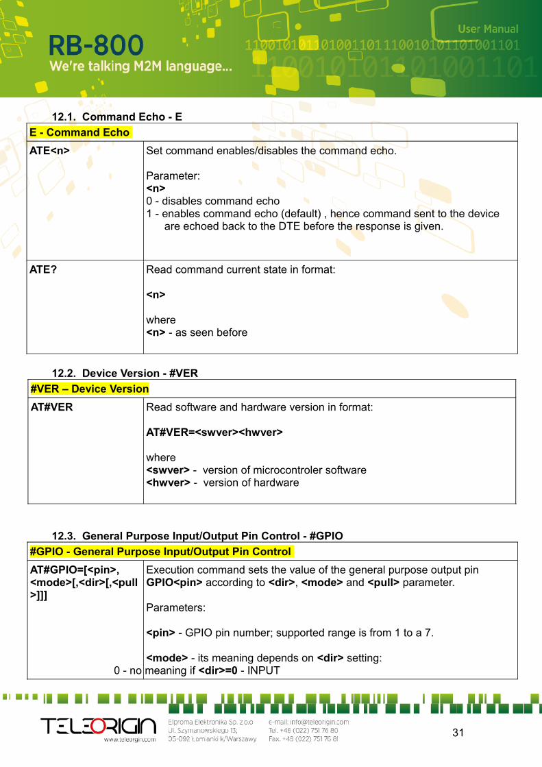
12.1. Command Echo - E
E - Command Echo
ATE<n> Set command enables/disables the command echo.
Parameter:<n>0 - disables command echo1 - enables command echo (default) , hence command sent to the device are echoed back to the DTE before the response is given.
ATE? Read command current state in format:
<n>
where <n> - as seen before
12.2. Device Version - #VER
#VER – Device Version
AT#VER Read software and hardware version in format:
AT#VER=<swver><hwver>
where<swver> - version of microcontroler software<hwver> - version of hardware
12.3. General Purpose Input/Output Pin Control - #GPIO
#GPIO - General Purpose Input/Output Pin Control
AT#GPIO=[<pin>,<mode>[,<dir>[,<pull>]]]
Execution command sets the value of the general purpose output pin GPIO<pin> according to <dir>, <mode> and <pull> parameter.
Parameters:
<pin> - GPIO pin number; supported range is from 1 to a 7.
<mode> - its meaning depends on <dir> setting:0 - no meaning if <dir>=0 - INPUT
31
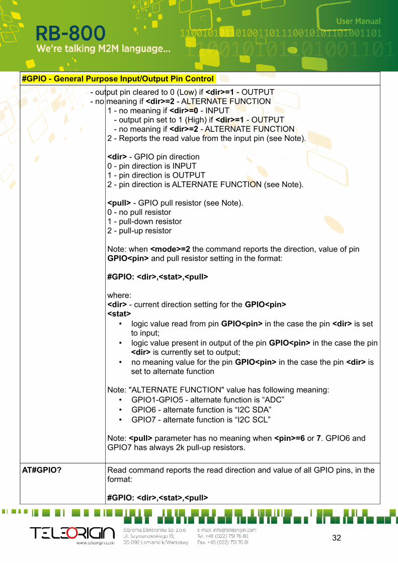
#GPIO - General Purpose Input/Output Pin Control
- output pin cleared to 0 (Low) if <dir>=1 - OUTPUT - no meaning if <dir>=2 - ALTERNATE FUNCTION
1 - no meaning if <dir>=0 - INPUT - output pin set to 1 (High) if <dir>=1 - OUTPUT - no meaning if <dir>=2 - ALTERNATE FUNCTION2 - Reports the read value from the input pin (see Note).
<dir> - GPIO pin direction0 - pin direction is INPUT 1 - pin direction is OUTPUT2 - pin direction is ALTERNATE FUNCTION (see Note).
<pull> - GPIO pull resistor (see Note).0 - no pull resistor1 - pull-down resistor2 - pull-up resistor
Note: when <mode>=2 the command reports the direction, value of pin GPIO<pin> and pull resistor setting in the format:
#GPIO: <dir>,<stat>,<pull>
where:<dir> - current direction setting for the GPIO<pin><stat>
• logic value read from pin GPIO<pin> in the case the pin <dir> is set to input;
• logic value present in output of the pin GPIO<pin> in the case the pin <dir> is currently set to output;
• no meaning value for the pin GPIO<pin> in the case the pin <dir> is set to alternate function
Note: "ALTERNATE FUNCTION" value has following meaning:• GPIO1-GPIO5 - alternate function is “ADC”• GPIO6 - alternate function is “I2C SDA” • GPIO7 - alternate function is “I2C SCL”
Note: <pull> parameter has no meaning when <pin>=6 or 7. GPIO6 and GPIO7 has always 2k pull-up resistors.
AT#GPIO? Read command reports the read direction and value of all GPIO pins, in the format:
#GPIO: <dir>,<stat>,<pull>
32
#GPIO - General Purpose Input/Output Pin Control
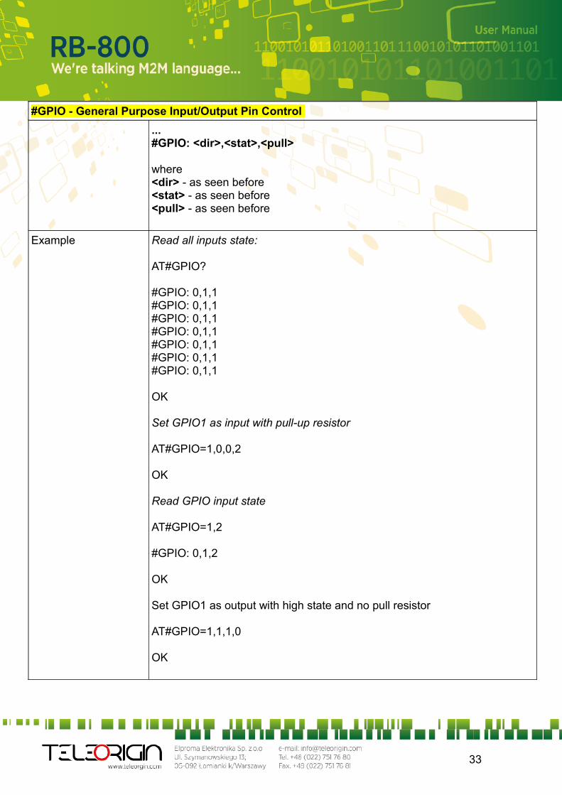
...#GPIO: <dir>,<stat>,<pull>
where <dir> - as seen before<stat> - as seen before<pull> - as seen before
Example Read all inputs state:
AT#GPIO?
#GPIO: 0,1,1#GPIO: 0,1,1#GPIO: 0,1,1#GPIO: 0,1,1#GPIO: 0,1,1#GPIO: 0,1,1#GPIO: 0,1,1
OK
Set GPIO1 as input with pull-up resistor
AT#GPIO=1,0,0,2
OK
Read GPIO input state
AT#GPIO=1,2
#GPIO: 0,1,2
OK
Set GPIO1 as output with high state and no pull resistor
AT#GPIO=1,1,1,0
OK
33
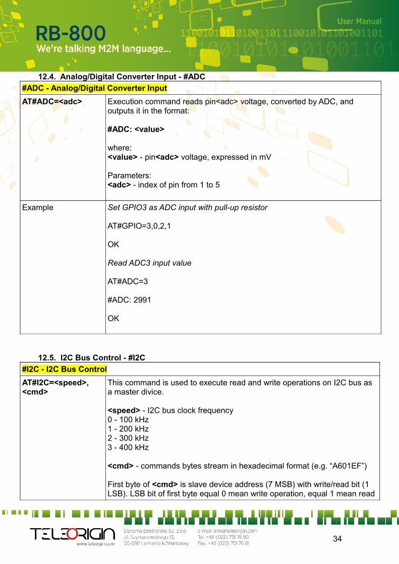
12.4. Analog/Digital Converter Input - #ADC
#ADC - Analog/Digital Converter Input
AT#ADC=<adc> Execution command reads pin<adc> voltage, converted by ADC, and outputs it in the format:
#ADC: <value>
where:<value> - pin<adc> voltage, expressed in mV
Parameters:<adc> - index of pin from 1 to 5
Example Set GPIO3 as ADC input with pull-up resistor
AT#GPIO=3,0,2,1
OK
Read ADC3 input value
AT#ADC=3
#ADC: 2991
OK
12.5. I2C Bus Control - #I2C
#I2C - I2C Bus Control
AT#I2C=<speed>,<cmd>
This command is used to execute read and write operations on I2C bus as a master divice.
<speed> - I2C bus clock frequency0 - 100 kHz1 - 200 kHz2 - 300 kHz3 - 400 kHz
<cmd> - commands bytes stream in hexadecimal format (e.g. “A601EF”)
First byte of <cmd> is slave device address (7 MSB) with write/read bit (1 LSB). LSB bit of first byte equal 0 mean write operation, equal 1 mean read
34
#I2C - I2C Bus Control
operation.
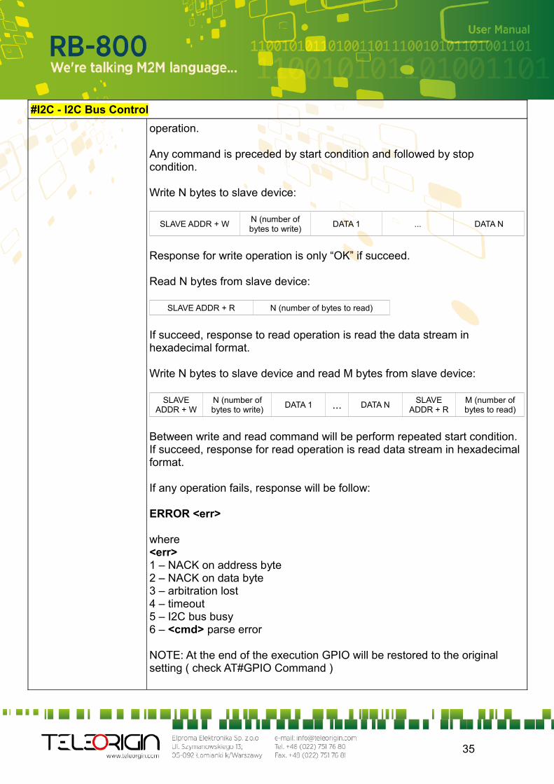
Any command is preceded by start condition and followed by stop condition.
Write N bytes to slave device:
SLAVE ADDR + WN (number of bytes to write)
DATA 1 ... DATA N
Response for write operation is only “OK” if succeed.
Read N bytes from slave device:
SLAVE ADDR + R N (number of bytes to read)
If succeed, response to read operation is read the data stream in hexadecimal format.
Write N bytes to slave device and read M bytes from slave device:
SLAVE ADDR + W
N (number of bytes to write)
DATA 1 ... DATA NSLAVE
ADDR + RM (number of bytes to read)
Between write and read command will be perform repeated start condition.If succeed, response for read operation is read data stream in hexadecimal format.
If any operation fails, response will be follow:
ERROR <err>
where<err>1 – NACK on address byte2 – NACK on data byte3 – arbitration lost4 – timeout5 – I2C bus busy6 – <cmd> parse error
NOTE: At the end of the execution GPIO will be restored to the original setting ( check AT#GPIO Command )
35
#I2C - I2C Bus Control
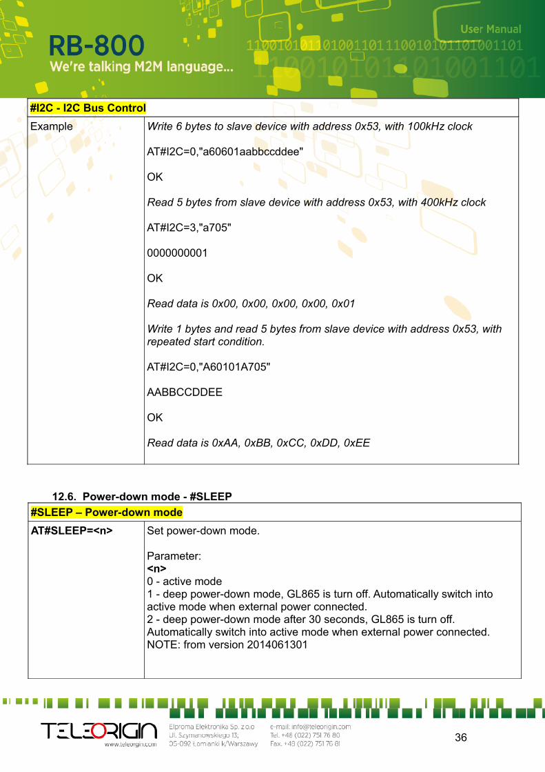
Example Write 6 bytes to slave device with address 0x53, with 100kHz clock
AT#I2C=0,"a60601aabbccddee"
OK
Read 5 bytes from slave device with address 0x53, with 400kHz clock
AT#I2C=3,"a705"
0000000001
OK
Read data is 0x00, 0x00, 0x00, 0x00, 0x01
Write 1 bytes and read 5 bytes from slave device with address 0x53, with repeated start condition.
AT#I2C=0,"A60101A705"
AABBCCDDEE
OK
Read data is 0xAA, 0xBB, 0xCC, 0xDD, 0xEE
12.6. Power-down mode - #SLEEP
#SLEEP – Power-down mode
AT#SLEEP=<n> Set power-down mode.
Parameter:<n>0 - active mode1 - deep power-down mode, GL865 is turn off. Automatically switch into active mode when external power connected.2 - deep power-down mode after 30 seconds, GL865 is turn off. Automatically switch into active mode when external power connected.NOTE: from version 2014061301
36
#SLEEP – Power-down mode
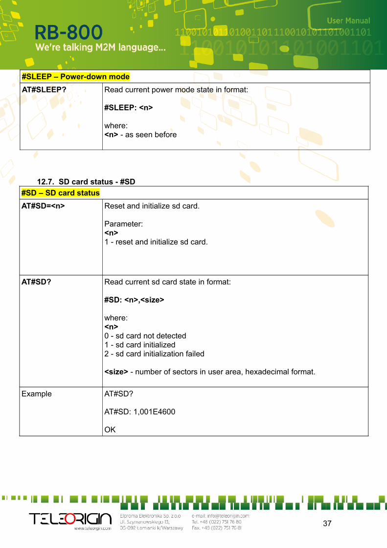
AT#SLEEP? Read current power mode state in format:
#SLEEP: <n>
where: <n> - as seen before
12.7. SD card status - #SD
#SD – SD card status
AT#SD=<n> Reset and initialize sd card.
Parameter:<n>1 - reset and initialize sd card.
AT#SD? Read current sd card state in format:
#SD: <n>,<size>
where: <n>0 - sd card not detected1 - sd card initialized2 - sd card initialization failed
<size> - number of sectors in user area, hexadecimal format.
Example AT#SD?
AT#SD: 1,001E4600
OK
37
12.8. SDRBLOCK read data block from memory card - #SDRBLOCK
#SDRBLOCK – Read data block from memory card
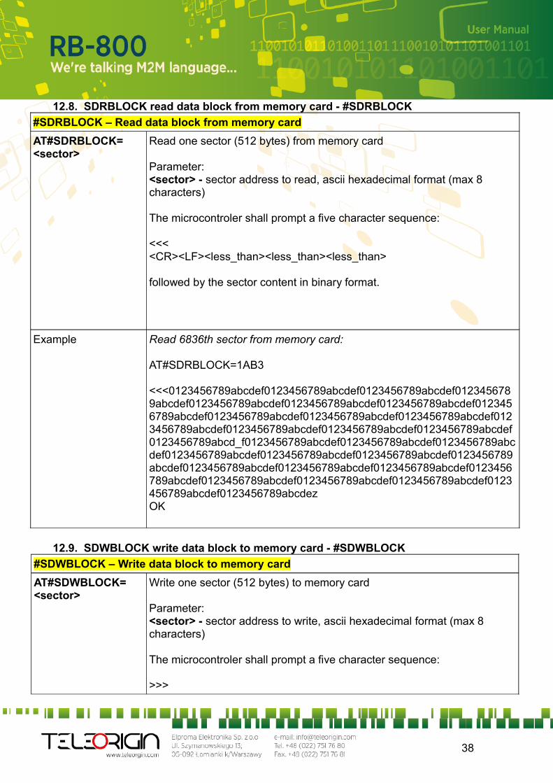
AT#SDRBLOCK=<sector>
Read one sector (512 bytes) from memory card
Parameter:<sector> - sector address to read, ascii hexadecimal format (max 8 characters)
The microcontroler shall prompt a five character sequence:
<<<<CR><LF><less_than><less_than><less_than>
followed by the sector content in binary format.
Example Read 6836th sector from memory card:
AT#SDRBLOCK=1AB3
<<<0123456789abcdef0123456789abcdef0123456789abcdef0123456789abcdef0123456789abcdef0123456789abcdef0123456789abcdef0123456789abcdef0123456789abcdef0123456789abcdef0123456789abcdef0123456789abcdef0123456789abcdef0123456789abcdef0123456789abcdef0123456789abcd_f0123456789abcdef0123456789abcdef0123456789abcdef0123456789abcdef0123456789abcdef0123456789abcdef0123456789abcdef0123456789abcdef0123456789abcdef0123456789abcdef0123456789abcdef0123456789abcdef0123456789abcdef0123456789abcdef0123456789abcdef0123456789abcdezOK
12.9. SDWBLOCK write data block to memory card - #SDWBLOCK
#SDWBLOCK – Write data block to memory card
AT#SDWBLOCK=<sector>
Write one sector (512 bytes) to memory card
Parameter:<sector> - sector address to write, ascii hexadecimal format (max 8 characters)
The microcontroler shall prompt a five character sequence:
>>>
38
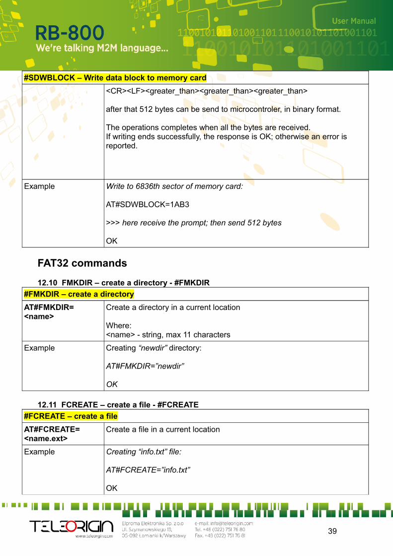
#SDWBLOCK – Write data block to memory card
<CR><LF><greater_than><greater_than><greater_than>
after that 512 bytes can be send to microcontroler, in binary format.
The operations completes when all the bytes are received.If writing ends successfully, the response is OK; otherwise an error is reported.
Example Write to 6836th sector of memory card:
AT#SDWBLOCK=1AB3
>>> here receive the prompt; then send 512 bytes
OK
FAT32 commands
12.10 FMKDIR – create a directory - #FMKDIR
#FMKDIR – create a directory
AT#FMKDIR= <name>
Create a directory in a current location
Where:<name> - string, max 11 characters
Example Creating “newdir” directory:
AT#FMKDIR=”newdir”
OK
12.11 FCREATE – create a file - #FCREATE
#FCREATE – create a file
AT#FCREATE= <name.ext>
Create a file in a current location
Example Creating “info.txt” file:
AT#FCREATE=”info.txt”
OK
39
12.12 FREMOVE – removing a file or directory - #FREMOVE
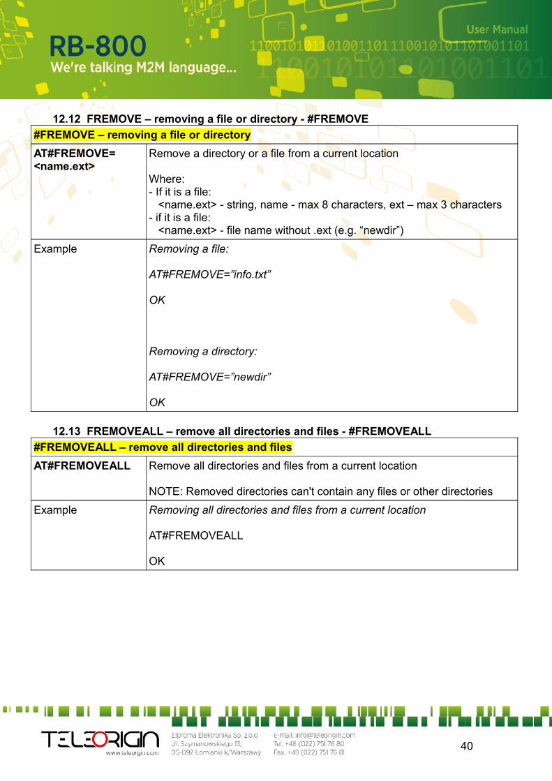
#FREMOVE – removing a file or directory
AT#FREMOVE=<name.ext>
Remove a directory or a file from a current location
Where:- If it is a file: <name.ext> - string, name - max 8 characters, ext – max 3 characters- if it is a file: <name.ext> - file name without .ext (e.g. “newdir”)
Example Removing a file:
AT#FREMOVE=”info.txt”
OK
Removing a directory:
AT#FREMOVE=”newdir”
OK
12.13 FREMOVEALL – remove all directories and files - #FREMOVEALL
#FREMOVEALL – remove all directories and files
AT#FREMOVEALL Remove all directories and files from a current location
NOTE: Removed directories can't contain any files or other directories
Example Removing all directories and files from a current location
AT#FREMOVEALL
OK
40
12.14 FCD – change current location - #FCD
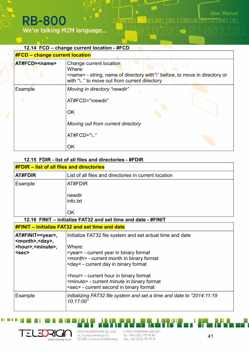
#FCD – change current location
AT#FCD=<name> Change current locationWhere:<name> - string, name of directory with”\” before, to move in directory or with “\..” to move out from current directory
Example Moving in directory “newdir”
AT#FCD=”\newdir”
OK
Moving out from current directory
AT#FCD=”\..”
OK
12.15 FDIR - list of all files and directories - #FDIR
#FDIR – list of all files and directories
AT#FDIR List of all files and directories in current location
Example AT#FDIR
newdirinfo.txt
OK
12.16 FINIT – initialize FAT32 and set time and date - #FINIT
#FINIT – initialize FAT32 and set time and date
AT#FINIT=<year>,<month>,<day>,<hour>,<minute>,<sec>
Initialize FAT32 file system and set actual time and date
Where:<year> - current year in binary format<month> - current month in binary format<day> - current day in binary format
<hour> - current hour in binary format<minute> - current minute in binary format<sec> - current second in binary format
Example Initializing FAT32 file system and set a time and date to “2014:11:19 10:17:00”
41
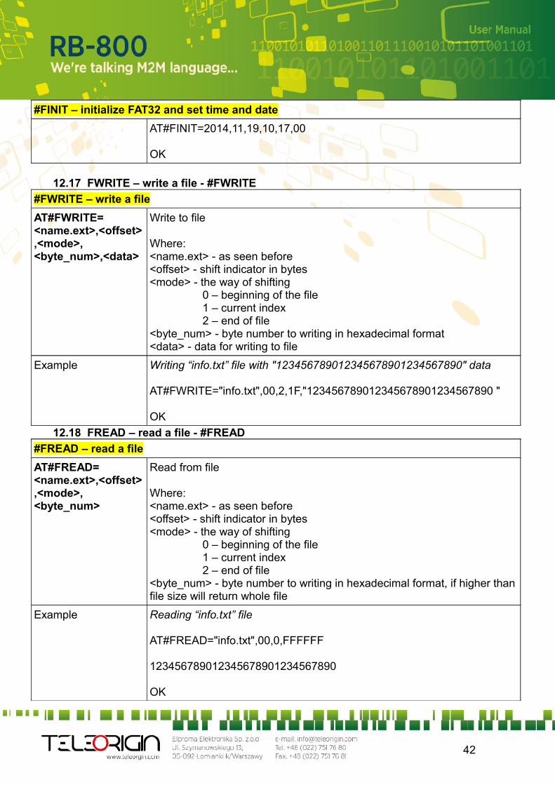
#FINIT – initialize FAT32 and set time and date
AT#FINIT=2014,11,19,10,17,00
OK
12.17 FWRITE – write a file - #FWRITE
#FWRITE – write a file
AT#FWRITE=<name.ext>,<offset>,<mode>,<byte_num>,<data>
Write to file
Where:<name.ext> - as seen before<offset> - shift indicator in bytes<mode> - the way of shifting 0 – beginning of the file 1 – current index 2 – end of file<byte_num> - byte number to writing in hexadecimal format<data> - data for writing to file
Example Writing “info.txt” file with "123456789012345678901234567890" data
AT#FWRITE="info.txt",00,2,1F,"123456789012345678901234567890 "
OK
12.18 FREAD – read a file - #FREAD
#FREAD – read a file
AT#FREAD=<name.ext>,<offset>,<mode>,<byte_num>
Read from file
Where:<name.ext> - as seen before<offset> - shift indicator in bytes<mode> - the way of shifting 0 – beginning of the file 1 – current index 2 – end of file<byte_num> - byte number to writing in hexadecimal format, if higher than file size will return whole file
Example Reading “info.txt” file
AT#FREAD="info.txt",00,0,FFFFFF
123456789012345678901234567890
OK
42
13. Safety recommendations
13.1 General Safety
Please follow safety regulations regarding the use of radio equipment due to the possibility of radio frequency interference. Read given advices carefully.
Switch off GSM terminal when: in an aircraft – using cellular telephones in aircraft may endanger the operation of
the aircraft; it is illegal at a refuelling point in any area with potentially explosive atmosphere which could cause an explosion
or fire in hospitals and any other places where medical equipment is in use
Respect restrictions on the use of radio equipment in any area or place where it is signalized that using cellular telephony is forbidden or dangerous.
Using GSM modem close to other electronic equipment may also cause interference if the equipment is inadequately protected. It may lead to damage or failure of GSM modem or the other equipment.
13.2 Care and Maintenance
The RB800 terminal is an electronic product that should be treated with care. Please follow suggestions shown below due to using modem for many years. Do not expose RB800 to any extreme circumstances like high temperature or high
humidity Do not keep modem in dirty and dust places Do not disassemble the RB800 modem Do not expose the modem to any water, rain or steam Do not drop, shake or knocking your modem Do not place your modem close to magnetic devices – credit cards, etc Use of third party equipment or accessories, not made or authorized by Elproma
Electronics may invalid the warranty of modem and/or cause failure or permanent damage of modem
Do not expose the modem to children under 3 years
13.3 Responsibility
The modem is under your responsibility. Please treat it with care, and respect local regulations. This is not a toy – keep it out of the reach of children.
Try to use security features (PIN etc.) to block unauthorized use or theft.
43

14. Accessories
The tables below shows recommended accessories for RB800 terminal.
14.1 Accessories critical for using modem
Table below shows accessories critical for using modem. Without them usage of modem is impossible.
Accessory Description Part no.Power adaptor 6 V
Example of power adaptor is shown in the picture below
Power adaptor 6V
44
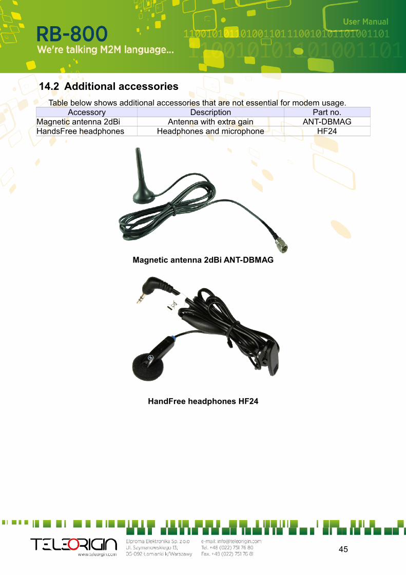
14.2 Additional accessories
Table below shows additional accessories that are not essential for modem usage.Accessory Description Part no.
Magnetic antenna 2dBi Antenna with extra gain ANT-DBMAGHandsFree headphones Headphones and microphone HF24
Magnetic antenna 2dBi ANT-DBMAG
HandFree headphones HF24
45
15. Conformity Assessment Issues
The RB800 has been assessed in order to satisfy the essential requirements of the R&TTE Directive 1999/05/EC (Radio Equipment & Telecommunications Terminal Equipments) to demonstrate the conformity against the harmonised standards with the final involvement of a Notified Body.
46

16. Safety Recommendations
READ CAREFULLY Be sure the use of this product is allowed in the country and in the environment
required. The use of this product may be dangerous and has to be avoided in the following areas:
• Where it can interfere with other electronic devices in environments such as hospitals, airports, aircrafts, etc
• Where there is risk of explosion such as gasoline stations, oil refineries, etc It is responsibility of the user to enforce the country regulation and the specific
environment regulation. Do not disassemble the product; any mark of tampering will compromise the warranty
validity. We recommend following the instructions of the hardware user guides for a correct
wiring of the product. The product has to be supplied with a stabilized voltage source and the wiring has to be conforming to the security and fire prevention regulations.
The product has to be handled with care, avoiding any contact with the pins because electrostatic discharges may damage the product itself. The same cautions have to be taken for the SIM, checking carefully the instruction for its use. Do not insert or remove the SIM when the product is in power saving mode.
The system integrator is responsible of the functioning of the final product; therefore, care has to be taken to the external components of the module, as well as of any project or installation issue, because the risk of disturbing the GSM network or external devices or having impact on the security. Should there be any doubt, please refer to the technical documentation and the regulations in force.
Every module has to be equipped with a proper antenna with specific characteristics. The antenna has to be installed with care in order to avoid any interference with other electronic devices and has to guarantee a minimum distance from the people (20 cm). In case of this requirement cannot be satisfied, the system integrator has to assess the final product against the SAR regulation.
47
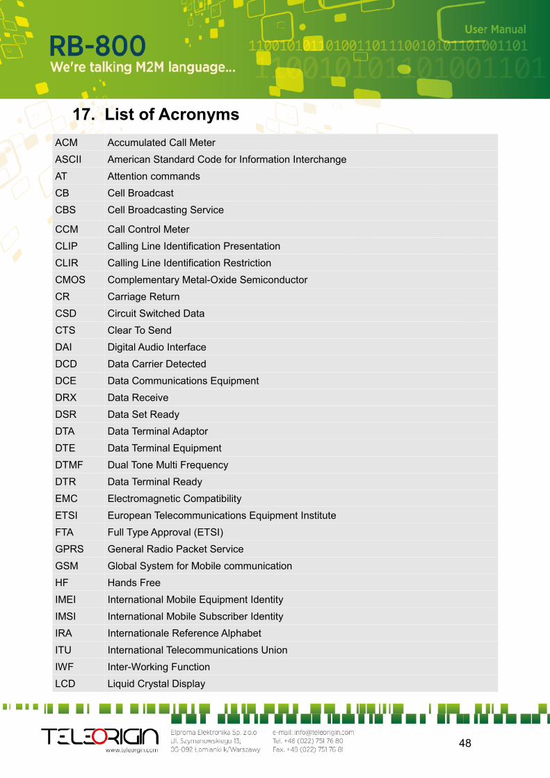
17. List of Acronyms
ACM Accumulated Call Meter
ASCII American Standard Code for Information Interchange
AT Attention commands
CB Cell Broadcast
CBS Cell Broadcasting Service
CCM Call Control Meter
CLIP Calling Line Identification Presentation
CLIR Calling Line Identification Restriction
CMOS Complementary Metal-Oxide Semiconductor
CR Carriage Return
CSD Circuit Switched Data
CTS Clear To Send
DAI Digital Audio Interface
DCD Data Carrier Detected
DCE Data Communications Equipment
DRX Data Receive
DSR Data Set Ready
DTA Data Terminal Adaptor
DTE Data Terminal Equipment
DTMF Dual Tone Multi Frequency
DTR Data Terminal Ready
EMC Electromagnetic Compatibility
ETSI European Telecommunications Equipment Institute
FTA Full Type Approval (ETSI)
GPRS General Radio Packet Service
GSM Global System for Mobile communication
HF Hands Free
IMEI International Mobile Equipment Identity
IMSI International Mobile Subscriber Identity
IRA Internationale Reference Alphabet
ITU International Telecommunications Union
IWF Inter-Working Function
LCD Liquid Crystal Display
48
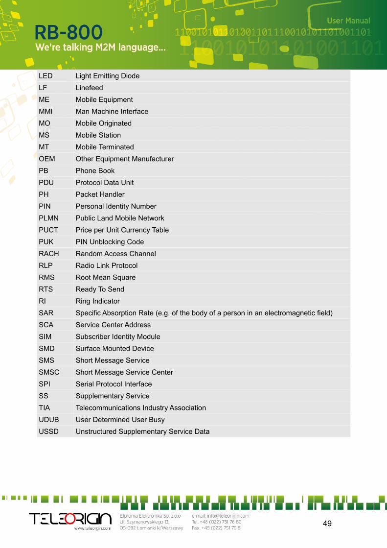
LED Light Emitting Diode
LF Linefeed
ME Mobile Equipment
MMI Man Machine Interface
MO Mobile Originated
MS Mobile Station
MT Mobile Terminated
OEM Other Equipment Manufacturer
PB Phone Book
PDU Protocol Data Unit
PH Packet Handler
PIN Personal Identity Number
PLMN Public Land Mobile Network
PUCT Price per Unit Currency Table
PUK PIN Unblocking Code
RACH Random Access Channel
RLP Radio Link Protocol
RMS Root Mean Square
RTS Ready To Send
RI Ring Indicator
SAR Specific Absorption Rate (e.g. of the body of a person in an electromagnetic field)
SCA Service Center Address
SIM Subscriber Identity Module
SMD Surface Mounted Device
SMS Short Message Service
SMSC Short Message Service Center
SPI Serial Protocol Interface
SS Supplementary Service
TIA Telecommunications Industry Association
UDUB User Determined User Busy
USSD Unstructured Supplementary Service Data
49
18. On-line support
Elproma provides a range on on-line support which includes: the latest version of this document the latest drivers for RB800
technical support
This information can be found on our web sites at www.teleorigin.com
For further information You can contact us at:email: [email protected]: www.elproma.fora.pl
tel.: +48 (22) 751 76 80fax.: +48 (22) 751 76 81
skype: elproma.elektronika
50