Embed Size (px)
Citation preview
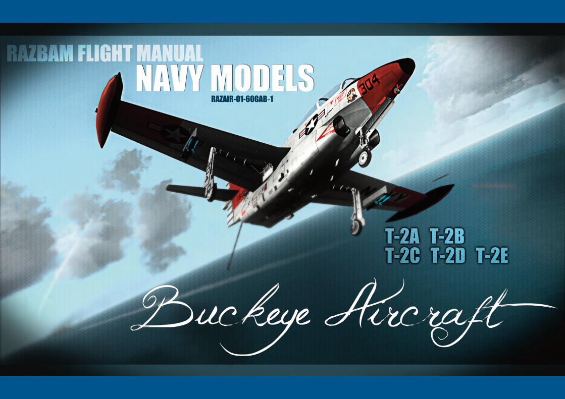
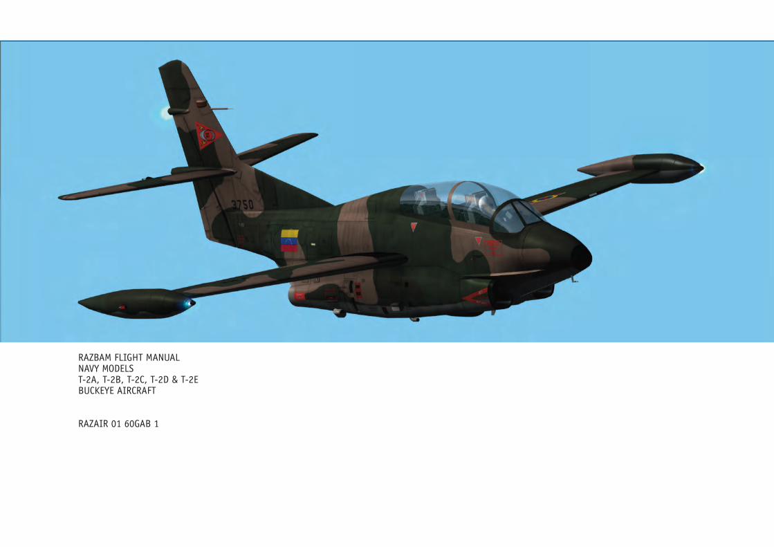
RAZBAM FLIGHT MANUALNAVY MODELST-2A, T-2B, T-2C, T-2D & T-2EBUCKEYE AIRCRAFT
RAZAIR�01�60GAB�1
Copyright © 2011-2012 by RAZBAM
. This package contains files and work by RAZBAM under permission.
3
RAZBAM Flight Manual - NAVY Models • T-2A, T-2B, T-2C, T-2D & T-2E BUCKEYE RAZAIR�01�60GAB�1
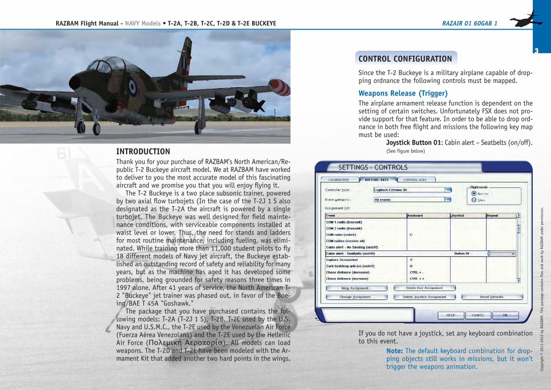
CONTROL CONFIGURATION
Since the T-2 Buckeye is a military airplane capable of drop-ping ordnance the following controls must be mapped.
Weapons Release (Trigger)The airplane armament release function is dependent on thesetting of certain switches. Unfortunately FSX does not pro-vide support for that feature. In order to be able to drop ord-nance in both free flight and missions the following key mapmust be used:
Joystick Button 01: Cabin alert – Seatbelts (on/off).(See figure below)
If you do not have a joystick, set any keyboard combinationto this event.
Note: The default keyboard combination for drop-ping objects still works in missions, but it won’ttrigger the weapons animation.
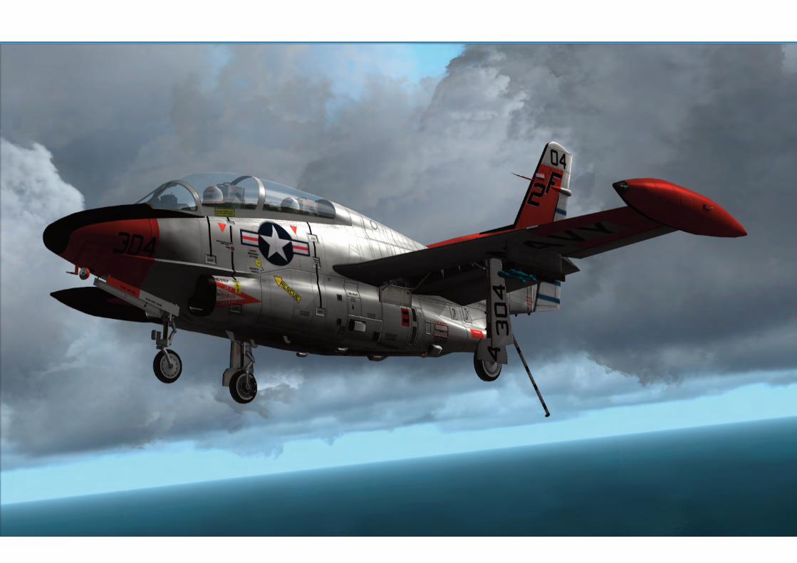
INTRODUCTIONThank you for your purchase of RAZBAM’s North American/Re-public T-2 Buckeye aircraft model. We at RAZBAM have workedto deliver to you the most accurate model of this fascinatingaircraft and we promise you that you will enjoy flying it.
The T-2 Buckeye is a two�place subsonic trainer, poweredby two axial flow turbojets (In the case of the T-2J�1�S alsodesignated as the T-2A the aircraft is powered by a singleturbojet. The Buckeye was well�designed for field mainte-nance conditions, with serviceable components installed atwaist level or lower. Thus, the need for stands and laddersfor most routine maintenance, including fueling, was elimi-nated. While training more than 11,000 student pilots to fly18 different models of Navy jet aircraft, the Buckeye estab-lished an outstanding record of safety and reliability for manyyears, but as the machine has aged it has developed someproblems, being grounded for safety reasons three times in1997 alone. After 41 years of service, the North American T-2 "Buckeye" jet trainer was phased out, in favor of the Boe-ing/BAE T�45A "Goshawk."
The package that you have purchased contains the fol-lowing models: T-2A (T-2J�1�S), T-2B. T-2C used by the U.S.Navy and U.S.M.C., the T-2E used by the Venezuelan Air Force(Fuerza Aérea Venezolana) and the T-2E used by the HellenicAir Force (Πολεμική Αεροπορία). All models can loadweapons. The T-2D and T-2E have been modeled with the Ar-mament Kit that added another two hard points in the wings.
4
RAZBAM Flight Manual - NAVY Models • T-2A, T-2B, T-2C, T-2D & T-2E BUCKEYE RAZAIR�01�60GAB�1
Copyright © 2011-2012 by RAZBAM
. This package contains files and work by RAZBAM under permission.
SWITCHES NAVIGATION
TheT-2’s cockpit instruments have several types of switches,pushbuttons, knobs and levers. Usually you only have to clickwith your left mouse�button on the switch to have it changeits position, but there are several that have multiple posi-tions that move back and forth. For these multiple positionswitches and knobs you have to left�click to go forward andright�click to go backwards.The following is a chart of the different switches and knobsfound on the cockpit and how to navigate them.Switch Type Navigation
Switch Type Navigation
2-Position Switch Left-Click changes the position.
3-Position Switch
Left-Click moves forward.Right-Click moves backwards.
Example:Left-Click: BOTH�OFF�UPPER.Right-Click: UPPER�OFF�BOTH.
Multi�position Knob Left-Click moves forward.Right-Click moves backwards.
Pushbutton Left-Click changes the position.
ThumbwheelLeft-Click moves forward.Right-Click moves backwards.Center wheel moves forward fast.
Rotating
Knob Left-Click moves forward.Right-Click moves backwards.Center when moves both forward andbackwards faster.
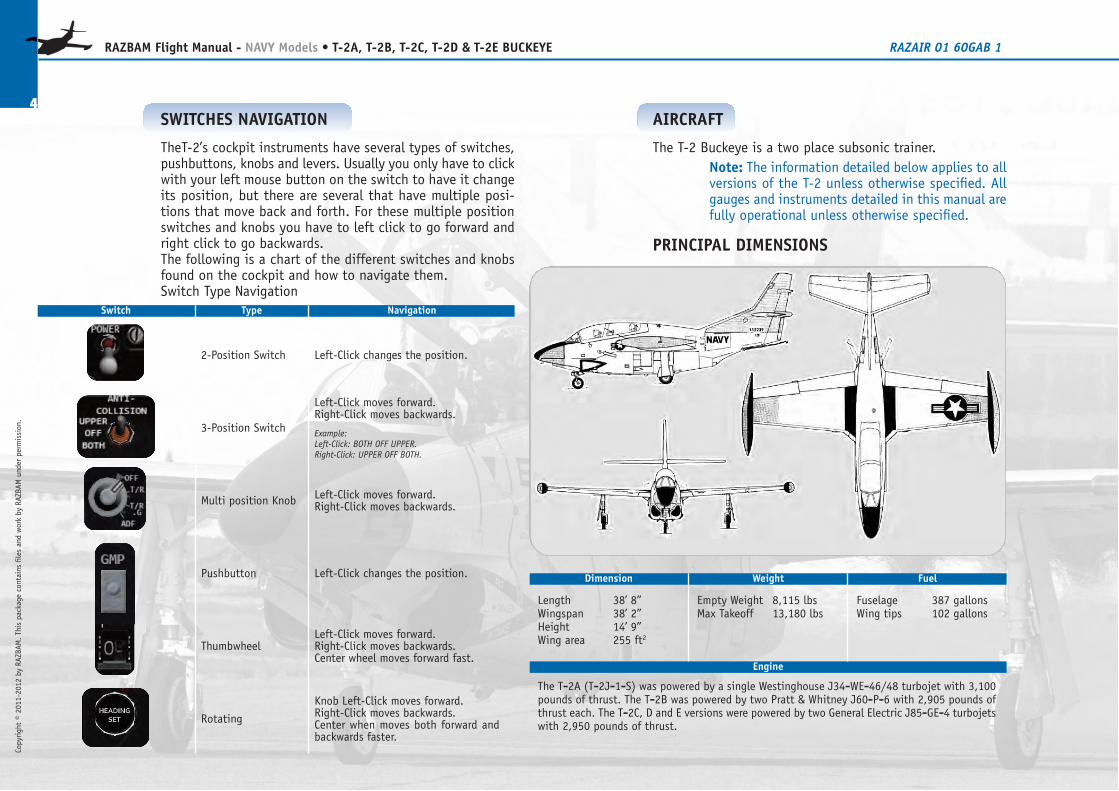
AIRCRAFT
The T-2 Buckeye is a two place subsonic trainer.Note: The information detailed below applies to allversions of the T-2 unless otherwise specified. Allgauges and instruments detailed in this manual arefully operational unless otherwise specified.
PRINCIPAL DIMENSIONS
Dimension Weight Fuel
Length 38’ 8”Wingspan 38’ 2”Height 14’ 9”Wing area 255 ft2
Empty Weight 8,115 lbsMax Takeoff 13,180 lbs
Fuselage 387 gallonsWing tips 102 gallons
Engine
The T‐2A (T‐2J‐1‐S) was powered by a single Westinghouse J34‐WE‐46/48 turbojet with 3,100pounds of thrust. The T‐2B was powered by two Pratt & Whitney J60‐P‐6 with 2,905 pounds ofthrust each. The T‐2C, D and E versions were powered by two General Electric J85‐GE‐4 turbojetswith 2,950 pounds of thrust.
Copyright © 2011-2012 by RAZBAM
. This package contains files and work by RAZBAM under permission.
5
RAZBAM Flight Manual - NAVY Models • T-2A, T-2B, T-2C, T-2D & T-2E BUCKEYE RAZAIR�01�60GAB�1
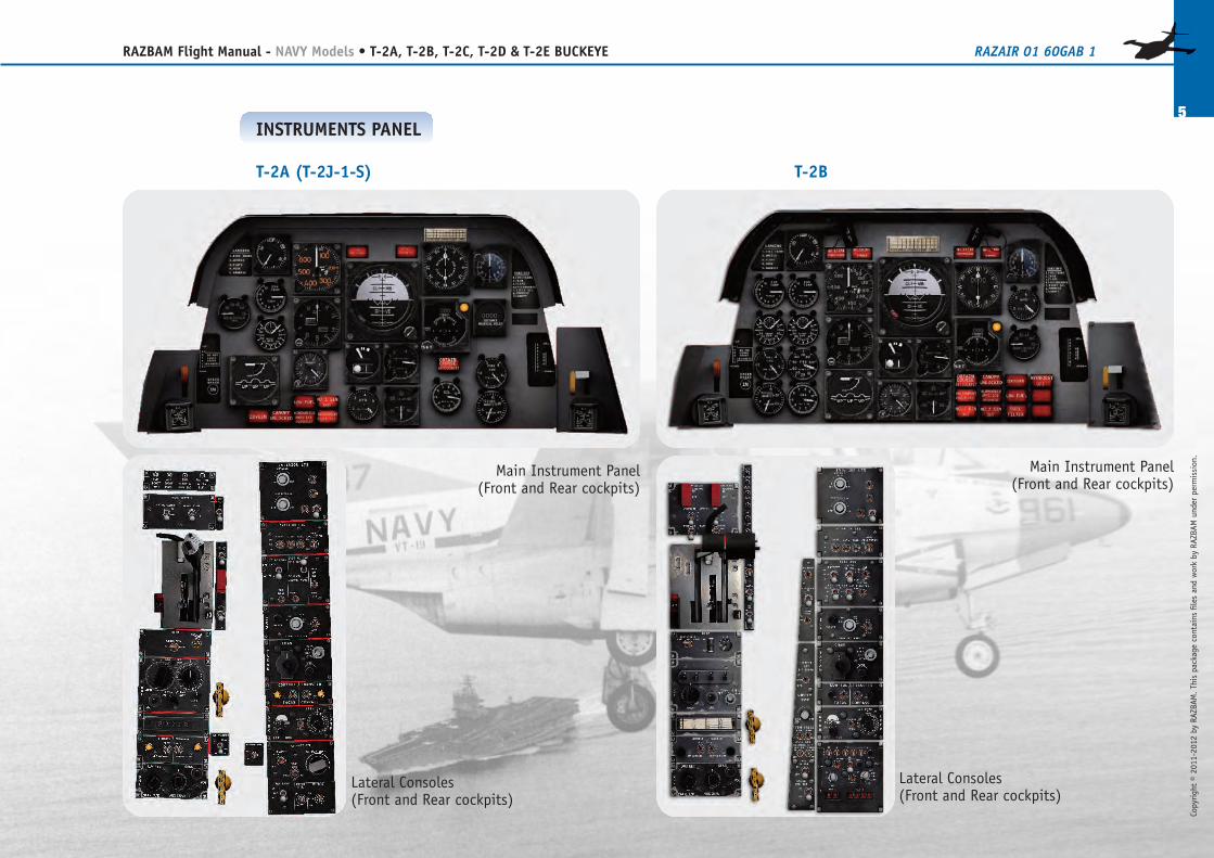
T-2B
Main Instrument Panel(Front and Rear cockpits)
Lateral Consoles(Front and Rear cockpits)
INSTRUMENTS PANEL
T-2A (T-2J-1-S)
Main Instrument Panel(Front and Rear cockpits)
Lateral Consoles(Front and Rear cockpits)
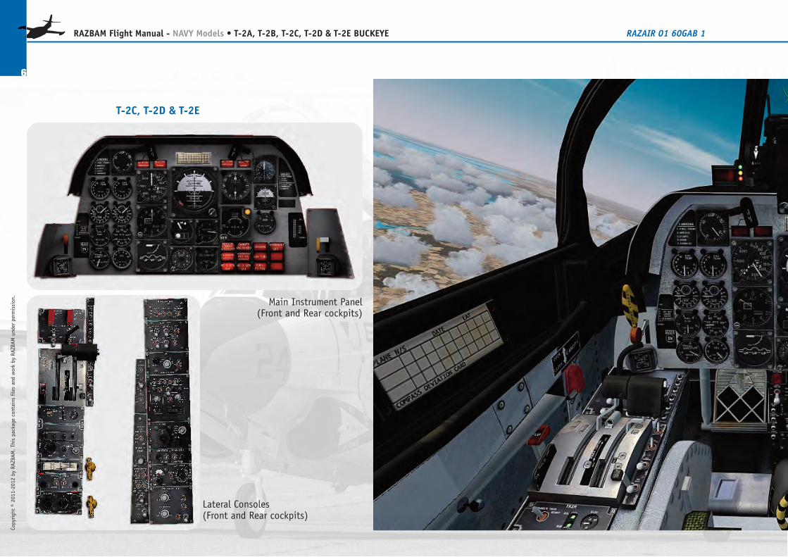
T-2C, T-2D & T-2E
Main Instrument Panel(Front and Rear cockpits)
Lateral Consoles(Front and Rear cockpits)
6
RAZBAM Flight Manual - NAVY Models • T-2A, T-2B, T-2C, T-2D & T-2E BUCKEYE RAZAIR�01�60GAB�1
Copyright © 2011-2012 by RAZBAM
. This package contains files and work by RAZBAM under permission.
Copyright © 2011-2012 by RAZBAM
. This package contains files and work by RAZBAM under permission.
7
RAZBAM Flight Manual - NAVY Models • T-2A, T-2B, T-2C, T-2D & T-2E BUCKEYE RAZAIR�01�60GAB�1
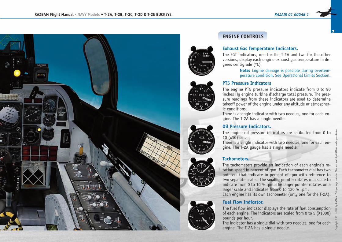
ENGINE CONTROLS
Exhaust Gas Temperature Indicators.The EGT indicators, one for the T-2A and two for the otherversions, display each engine exhaust gas temperature in de-grees centigrade (ºC)
Note: Engine damage is possible during overtem-perature condition. See Operational Limits Section.
PT5 Pressure IndicatorsThe engine PT5 pressure indicators indicate from 0 to 90inches Hg engine turbine discharge total pressure. The pres-sure readings from these indicators are used to determinetakeoff power of the engine under any altitude or atmospher-ic conditions.There is a single indicator with two needles, one for each en-gine. The T-2A has a single needle.
Oil Pressure Indicators.The engine oil pressure indicators are calibrated from 0 to10 (x10) psi.There is a single indicator with two needles, one for each en-gine. The T-2A gauge has a single needle.
Tachometers.The tachometers provide an indication of each engine’s ro-tation speed in percent of rpm. Each tachometer dial has twopointers that indicate in percent of rpm with reference totwo separate scales. The smaller pointer rotates in a scale toindicate from 0 to 10 % rpm. The larger pointer rotates on alarger scale and indicates from 0 to 120 % rpm.Each engine has its own tachometer (only one for the T-2A).
Fuel Flow Indicator.The fuel flow indicator displays the rate of fuel consumptionof each engine. The indicators are scaled from 0 to 5 (X1000)pounds per hour.The indicator has a single dial with two needles, one for eachengine. The T-2A has a single needle.
ENGINE MASTER SwitchThe engine master switches (there is only one in the T-2A)control the fuel shut�off valve for each engine. They must bein the ON position for the engine to be used.
ENGINE STARTER SwitchThe engine STARTER switch initiates the starting cycle. Leftclicking on it will place it on the START position and the en-gine start sequence will begin. All versions except T-2A:Right clicking will place the switch on the STOP position andwill cancel the engine start sequence. Releasing the mousebutton will return the switch to the OFF position.
Note: For all versions except the T-2A, the ENGINESTART sequence will begin only if the aircraft is onthe ground.
ENGINE AIRSTART Switch (Not available in the T-2A)The engine airstart switch will initiate the engine start-ing cycle.The start sequence will initiate with the aircraft either in theground or in the air. The switches are covered to preventdamage to the igniters and should remain OFF.
ENGINE START SEQUENCE PROCEDURETo start the engines proceed as follows:
1. Click the MASTER ENGINE switch to the ON posi-tion.
2. Click on the ENGINE START switch. The sequencewill begin.
Repeat the sequence for the No. 2 EngineNot applicable to the T-2ANOTE: Either engine can be started first.
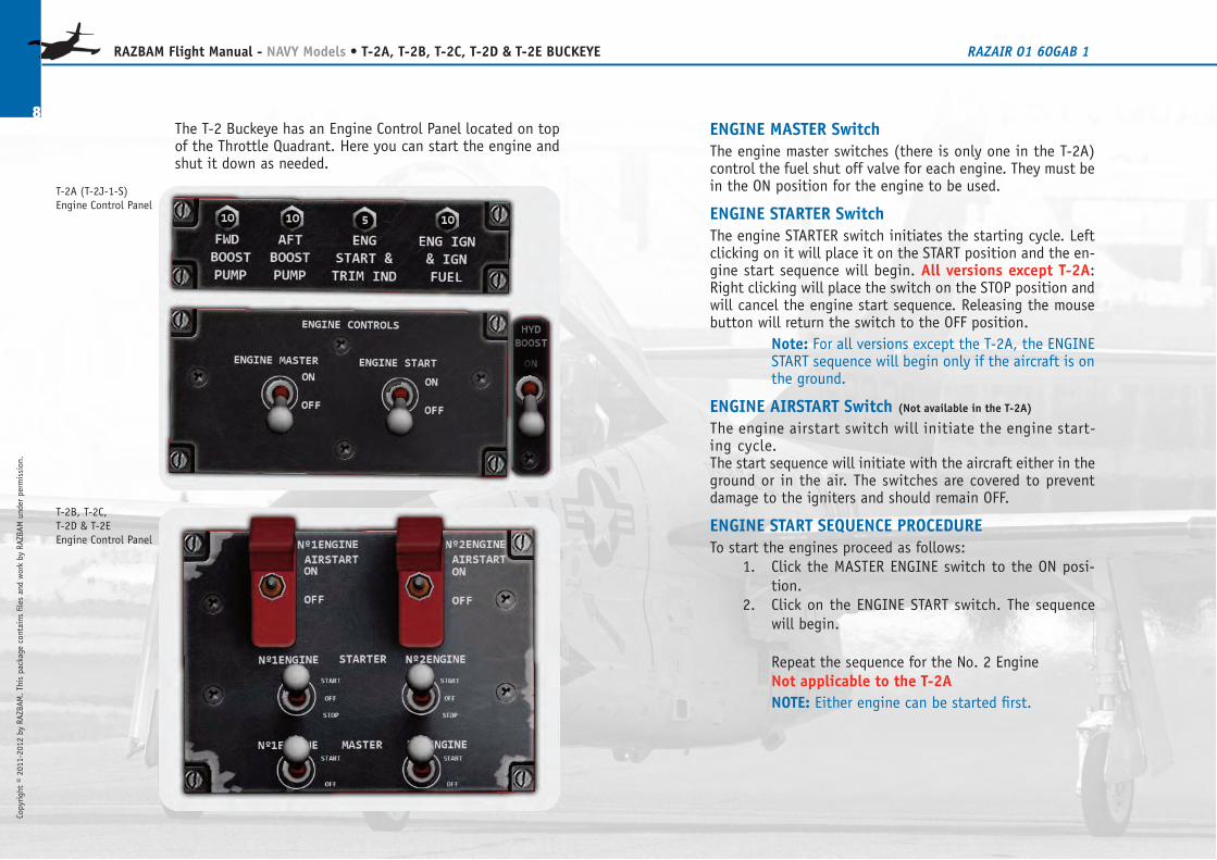
The T-2 Buckeye has an Engine Control Panel located on topof the Throttle Quadrant. Here you can start the engine andshut it down as needed.
8
RAZBAM Flight Manual - NAVY Models • T-2A, T-2B, T-2C, T-2D & T-2E BUCKEYE RAZAIR�01�60GAB�1
Copyright © 2011-2012 by RAZBAM
. This package contains files and work by RAZBAM under permission.
T-2A (T-2J-1-S)Engine Control Panel
T-2B, T-2C,T-2D & T-2EEngine Control Panel
Copyright © 2011-2012 by RAZBAM
. This package contains files and work by RAZBAM under permission.
9
RAZBAM Flight Manual - NAVY Models • T-2A, T-2B, T-2C, T-2D & T-2E BUCKEYE RAZAIR�01�60GAB�1
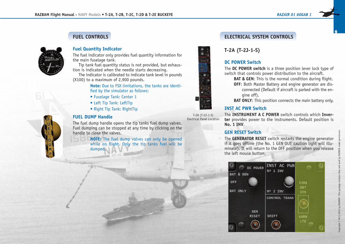
FUEL CONTROLS
Fuel Quantity IndicatorThe fuel indicator only provides fuel quantity information forthe main fuselage tank.
Tip�tank fuel quantity status is not provided, but exhaus-tion is indicated when the needle starts decreasing.
The indicator is calibrated to indicate tank level in pounds(X100) to a maximum of 2,900 pounds.
Note: Due to FSX limitations, the tanks are identi-fied by the simulator as follows:• Fuselage Tank: Center 1• Left Tip Tank: LeftTip• Right Tip Tank: RightTip
FUEL DUMP HandleThe fuel dump handle opens the tip tanks fuel dump valves.Fuel dumping can be stopped at any time by clicking on thehandle to close the valves.
NOTE: The fuel dump valves can only be openedwhile on flight. Only the tip tanks fuel will bedumped.
ELECTRICAL SYSTEM CONTROLS
T-2A (T-2J-1-S)
DC POWER SwitchThe DC POWER switch is a three�position lever�lock type ofswitch that controls power distribution to the aircraft.
BAT & GEN: This is the normal condition during flight.OFF: Both Master Battery and engine generator are dis-
connected (Default if aircraft is parked with the en-gine off).
BAT ONLY: This position connects the main battery only.
INST AC PWR SwitchThe INSTRUMENT A�C POWER switch controls which Inver-ter provides power to the instruments. Default position isNo. 1 INV.
GEN RESET SwitchThe GENERATOR RESET switch restarts the engine generatorif it goes offline (the No. 1 GEN OUT caution light will illu-minate). It will return to the OFF position when you releasethe left mouse button.
T-2A (T-2J-1-S)Electrical Panel Location
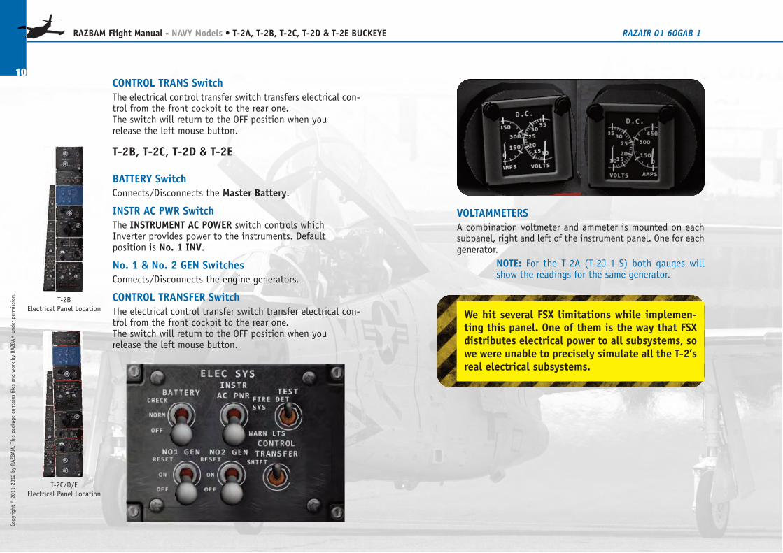
VOLTAMMETERSA combination voltmeter and ammeter is mounted on eachsubpanel, right and left of the instrument panel. One for eachgenerator.
NOTE: For the T-2A (T-2J-1-S) both gauges willshow the readings for the same generator.
CONTROL TRANS SwitchThe electrical control transfer switch transfers electrical con-trol from the front cockpit to the rear one.The switch will return to the OFF position when yourelease the left mouse button.
T-2B, T-2C, T-2D & T-2E
BATTERY SwitchConnects/Disconnects the Master Battery.
INSTR AC PWR SwitchThe INSTRUMENT AC POWER switch controls whichInverter provides power to the instruments. Defaultposition is No. 1 INV.
No. 1 & No. 2 GEN SwitchesConnects/Disconnects the engine generators.
CONTROL TRANSFER SwitchThe electrical control transfer switch transfer electrical con-trol from the front cockpit to the rear one.The switch will return to the OFF position when yourelease the left mouse button.
10
RAZBAM Flight Manual - NAVY Models • T-2A, T-2B, T-2C, T-2D & T-2E BUCKEYE RAZAIR�01�60GAB�1
Copyright © 2011-2012 by RAZBAM
. This package contains files and work by RAZBAM under permission.
T-2BElectrical Panel Location
T-2C/D/EElectrical Panel Location
We hit several FSX limitations while implemen-ting this panel. One of them is the way that FSXdistributes electrical power to all subsystems, sowe were unable to precisely simulate all the T-2’sreal electrical subsystems.
Copyright © 2011-2012 by RAZBAM
. This package contains files and work by RAZBAM under permission.
11
RAZBAM Flight Manual - NAVY Models • T-2A, T-2B, T-2C, T-2D & T-2E BUCKEYE RAZAIR�01�60GAB�1
T-2B, T-2C, T-2D & T-2E
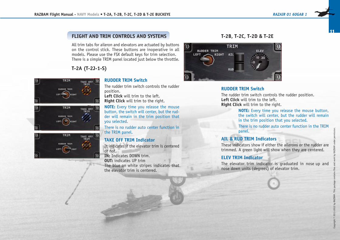
RUDDER TRIM SwitchThe rudder trim switch controls the rudder position.Left Click will trim to the left.Right Click will trim to the right.
NOTE: Every time you release the mouse button,the switch will center, but the rudder will remainin the trim position that you selected.There is no rudder auto�center function in the TRIMpanel.
AIL & RUD TRIM IndicatorsThese indicators show if either the ailerons or the rudder aretrimmed. A green light will show when they are centered.
ELEV TRIM IndicatorThe elevator trim indicator is graduated in nose�up andnose�down units (degrees) of elevator trim.
FLIGHT AND TRIM CONTROLS AND SYSTEMS
All trim tabs for aileron and elevators are actuated by buttonson the control stick. These buttons are inoperative in allmodels. Please use the FSX default keys for trim selection.There is a simple TRIM panel located just below the throttle.
T-2A (T-2J-1-S)
RUDDER TRIM SwitchThe rudder trim switch controls the rudderposition.Left Click will trim to the left.Right Click will trim to the right.NOTE: Every time you release the mousebutton, the switch will center, but the rud-der will remain in the trim position thatyou selected.There is no rudder auto�center function inthe TRIM panel.
TAKE OFF TRIM IndicatorIt indicates if the elevator trim is centeredor not.IN: Indicates DOWN trim.OUT: indicates UP trimThe blue�on�white stripes indicates thatthe elevator trim is centered.
12
RAZBAM Flight Manual - NAVY Models • T-2A, T-2B, T-2C, T-2D & T-2E BUCKEYE RAZAIR�01�60GAB�1
Copyright © 2011-2012 by RAZBAM
. This package contains files and work by RAZBAM under permission.
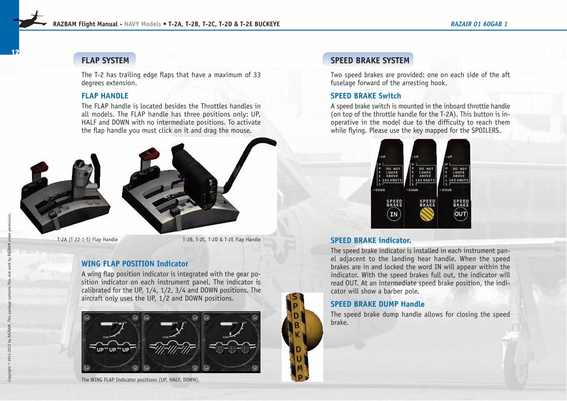
The WING FLAP Indicator positions (UP, HALF, DOWN).
FLAP SYSTEM
The T-2 has trailing edge flaps that have a maximum of 33degrees extension.
FLAP HANDLEThe FLAP handle is located besides the Throttles handles inall models. The FLAP handle has three positions only: UP,HALF and DOWN with no intermediate positions. To activatethe flap handle you must click on it and drag the mouse.
WING FLAP POSITION IndicatorA wing flap position indicator is integrated with the gear po-sition indicator on each instrument panel. The indicator iscalibrated for the UP, 1/4, 1/2, 3/4 and DOWN positions. Theaircraft only uses the UP, 1/2 and DOWN positions.
T-2B, T-2C, T-2D & T-2E Flap HandleT-2A (T-2J-1-S) Flap Handle
SPEED BRAKE SYSTEM
Two speed brakes are provided: one on each side of the aftfuselage forward of the arresting hook.
SPEED BRAKE SwitchA speed brake switch is mounted in the inboard throttle handle(on top of the throttle handle for the T-2A). This button is in-operative in the model due to the difficulty to reach themwhile flying. Please use the key mapped for the SPOILERS.
SPEED BRAKE indicator.The speed brake indicator is installed in each instrument pan-el adjacent to the landing hear handle. When the speedbrakes are in and locked the word IN will appear within theindicator. With the speed brakes full out, the indicator willread OUT. At an intermediate speed brake position, the indi-cator will show a barber pole.
SPEED BRAKE DUMP HandleThe speed brake dump handle allows for closing the speedbrake.
Copyright © 2011-2012 by RAZBAM
. This package contains files and work by RAZBAM under permission.
13
RAZBAM Flight Manual - NAVY Models • T-2A, T-2B, T-2C, T-2D & T-2E BUCKEYE RAZAIR�01�60GAB�1
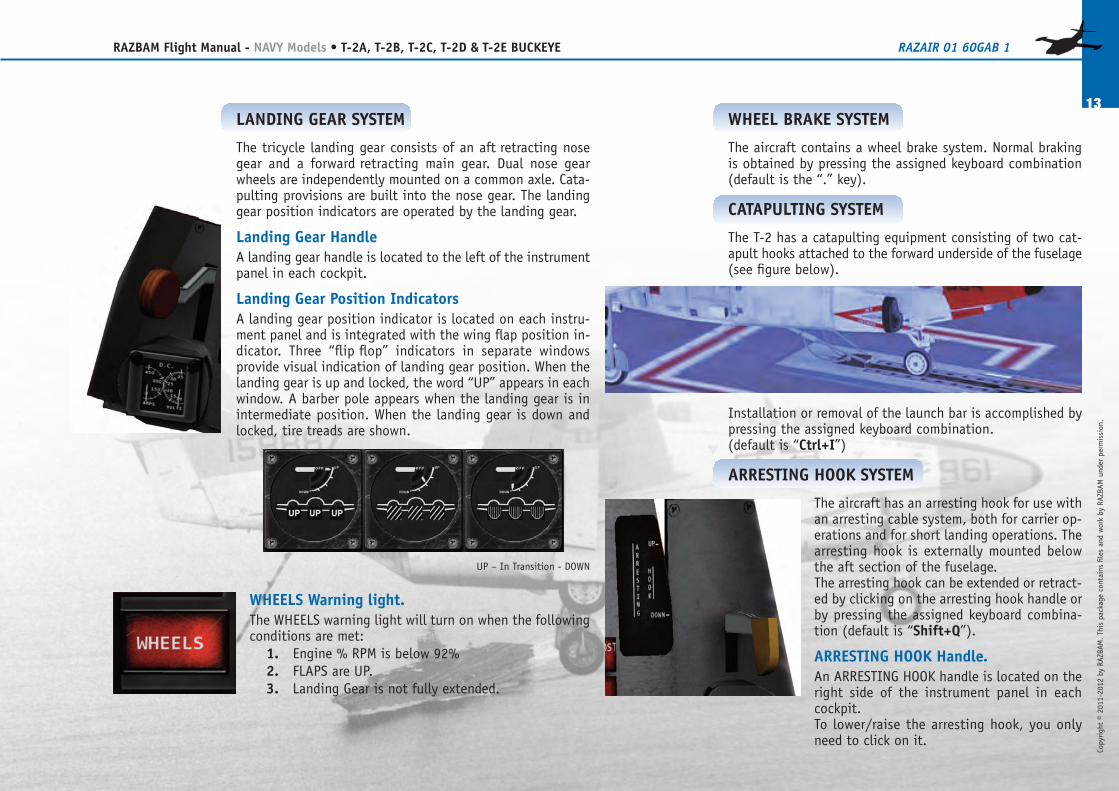
LANDING GEAR SYSTEM
The tricycle landing gear consists of an aft�retracting nosegear and a forward�retracting main gear. Dual nose gearwheels are independently mounted on a common axle. Cata-pulting provisions are built into the nose gear. The landinggear position indicators are operated by the landing gear.
Landing Gear HandleA landing gear handle is located to the left of the instrumentpanel in each cockpit.
Landing Gear Position IndicatorsA landing gear position indicator is located on each instru-ment panel and is integrated with the wing flap position in-dicator. Three “flip�flop” indicators in separate windowsprovide visual indication of landing gear position. When thelanding gear is up and locked, the word “UP” appears in eachwindow. A barber pole appears when the landing gear is inintermediate position. When the landing gear is down andlocked, tire treads are shown.
WHEELS Warning light.The WHEELS warning light will turn on when the followingconditions are met:
1. Engine % RPM is below 92%2. FLAPS are UP.3. Landing Gear is not fully extended.
UP – In Transition - DOWN
WHEEL BRAKE SYSTEM
The aircraft contains a wheel brake system. Normal brakingis obtained by pressing the assigned keyboard combination(default is the “.” key).
CATAPULTING SYSTEM
The T-2 has a catapulting equipment consisting of two cat-apult hooks attached to the forward underside of the fuselage(see figure below).
Installation or removal of the launch bar is accomplished bypressing the assigned keyboard combination.(default is “Ctrl+I”)
ARRESTING HOOK SYSTEM
The aircraft has an arresting hook for use withan arresting cable system, both for carrier op-erations and for short landing operations. Thearresting hook is externally mounted belowthe aft section of the fuselage.The arresting hook can be extended or retract-ed by clicking on the arresting hook handle orby pressing the assigned keyboard combina-tion (default is “Shift+Q”).
ARRESTING HOOK Handle.An ARRESTING HOOK handle is located on theright side of the instrument panel in eachcockpit.To lower/raise the arresting hook, you onlyneed to click on it.
T-2B, T-2C, T-2D & T-2E
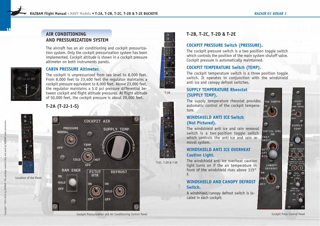
COCKPIT PRESSURE Switch (PRESSURE).The cockpit pressure switch is a two�position toggle switchwhich controls the position of the main system shutoff valve.Cockpit pressure is automatically maintained.
COCKPIT TEMPERATURE Switch (TEMP).The cockpit temperature switch is a three�position toggleswitch. It operates in conjunction with the windshieldanti�ice and canopy defrost switches.
SUPPLY TEMPERATURE Rheostat(SUPPLY TEMP).The supply temperature rheostat providesautomatic control of the cockpit tempera-ture.
WINDSHIELD ANTI�ICE Switch(Not Pictured).The windshield anti�ice and rain removalswitch is a two�position toggle switchwhich controls the anti�ice and rain re-moval system.
WINDSHIELD ANTI�ICE OVERHEATCaution Light.The windshield anti�ice overheat cautionlight turns on if the air temperature infront of the windshield rises above 315°F.
WINDSHIELD AND CANOPY DEFROSTSwitch.A windshield/canopy defrost switch is lo-cated in each cockpit.
14
RAZBAM Flight Manual - NAVY Models • T-2A, T-2B, T-2C, T-2D & T-2E BUCKEYE RAZAIR�01�60GAB�1
Copyright © 2011-2012 by RAZBAM
. This package contains files and work by RAZBAM under permission.
Cockpit Pressurization and Air Conditioning Control Panel
Location of the Panel
AIR�CONDITIONINGAND PRESSURIZATION SYSTEM
The aircraft has an air conditioning and cockpit pressuriza-tion system. Only the cockpit pressurization system has beenimplemented. Cockpit altitude is shown in a cockpit pressurealtimeter on both instruments panels.
CABIN PRESSURE Altimeter.The cockpit is unpressurized from sea level to 8,000 feet.From 8,000 feet to 23,400 feet the regulator maintains acockpit pressure equivalent to 8,000 feet. Above 23,000 feet,the regulator maintains a 5.0 psi pressure differential be-tween cockpit and flight altitude pressures. At flight altitudeof 50,000 feet, the cockpit pressure is about 20,000 feet.
T-2A (T-2J-1-S)
T-2C, T-2D & T-2E
Cockpit Press Control Panel
T-2B
Copyright © 2011-2012 by RAZBAM
. This package contains files and work by RAZBAM under permission.
15
RAZBAM Flight Manual - NAVY Models • T-2A, T-2B, T-2C, T-2D & T-2E BUCKEYE RAZAIR�01�60GAB�1
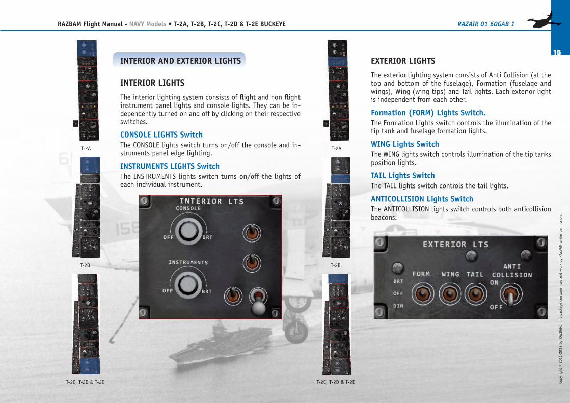
EXTERIOR LIGHTS
The exterior lighting system consists of Anti�Collision (at thetop and bottom of the fuselage), Formation (fuselage andwings), Wing (wing tips) and Tail lights. Each exterior lightis independent from each other.
Formation (FORM) Lights Switch.The Formation Lights switch controls the illumination of thetip tank and fuselage formation lights.
WING Lights SwitchThe WING lights switch controls illumination of the tip tanksposition lights.
TAIL Lights SwitchThe TAIL lights switch controls the tail lights.
ANTICOLLISION Lights SwitchThe ANTICOLLISION lights switch controls both anticollisionbeacons.
INTERIOR AND EXTERIOR LIGHTS
INTERIOR LIGHTS
The interior lighting system consists of flight and non�flightinstrument panel lights and console lights. They can be in-dependently turned on and off by clicking on their respectiveswitches.
CONSOLE LIGHTS SwitchThe CONSOLE lights switch turns on/off the console and in-struments panel edge lighting.
INSTRUMENTS LIGHTS SwitchThe INSTRUMENTS lights switch turns on/off the lights ofeach individual instrument.
T-2B
T-2A
T-2B
T-2A
T-2C, T-2D & T-2E T-2C, T-2D & T-2E
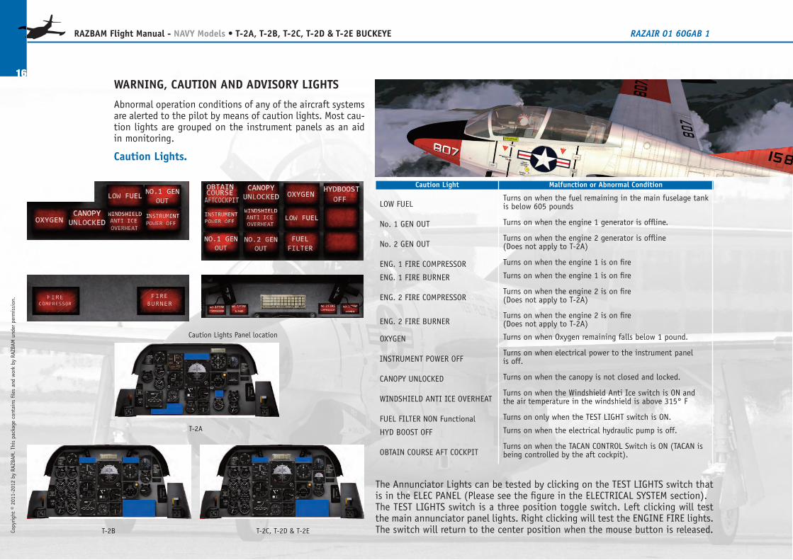
The Annunciator Lights can be tested by clicking on the TEST LIGHTS switch thatis in the ELEC PANEL (Please see the figure in the ELECTRICAL SYSTEM section).The TEST LIGHTS switch is a three position toggle switch. Left clicking will testthe main annunciator panel lights. Right clicking will test the ENGINE FIRE lights.The switch will return to the center position when the mouse button is released.
WARNING, CAUTION AND ADVISORY LIGHTS
Abnormal operation conditions of any of the aircraft systemsare alerted to the pilot by means of caution lights. Most cau-tion lights are grouped on the instrument panels as an aidin monitoring.
Caution Lights.
16
RAZBAM Flight Manual - NAVY Models • T-2A, T-2B, T-2C, T-2D & T-2E BUCKEYE RAZAIR�01�60GAB�1
Copyright © 2011-2012 by RAZBAM
. This package contains files and work by RAZBAM under permission.
Caution Light Malfunction or Abnormal Condition
LOW FUELTurns on when the fuel remaining in the main fuselage tankis below 605 pounds
No. 1 GEN OUT Turns on when the engine 1 generator is offline.
No. 2 GEN OUTTurns on when the engine 2 generator is offline(Does not apply to T-2A)
ENG. 1 FIRE COMPRESSOR Turns on when the engine 1 is on fire
ENG. 1 FIRE BURNER Turns on when the engine 1 is on fire
ENG. 2 FIRE COMPRESSORTurns on when the engine 2 is on fire(Does not apply to T-2A)
ENG. 2 FIRE BURNERTurns on when the engine 2 is on fire(Does not apply to T-2A)
OXYGEN Turns on when Oxygen remaining falls below 1 pound.
INSTRUMENT POWER OFFTurns on when electrical power to the instrument panelis off.
CANOPY UNLOCKED Turns on when the canopy is not closed and locked.
WINDSHIELD ANTI�ICE OVERHEATTurns on when the Windshield Anti�Ice switch is ON andthe air temperature in the windshield is above 315° F
FUEL FILTER NON Functional Turns on only when the TEST LIGHT switch is ON.
HYD BOOST OFF Turns on when the electrical hydraulic pump is off.
OBTAIN COURSE AFT COCKPITTurns on when the TACAN CONTROL Switch is ON (TACAN isbeing controlled by the aft cockpit).
T-2A
T-2B T-2C, T-2D & T-2E
Caution Lights Panel location
Copyright © 2011-2012 by RAZBAM
. This package contains files and work by RAZBAM under permission.
17
RAZBAM Flight Manual - NAVY Models • T-2A, T-2B, T-2C, T-2D & T-2E BUCKEYE RAZAIR�01�60GAB�1
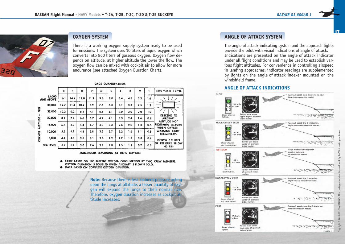
OXYGEN SYSTEM
There is a working oxygen supply system ready to be usedfor missions. The system uses 10 liters of liquid oxygen whichconverts into 860 liters of gaseous oxygen. Oxygen flow de-pends on altitude, at higher altitude the lower the flow. Theoxygen flow can be mixed with cockpit air to allow for moreendurance (see attached Oxygen Duration Chart).
Note: Because there is less ambient pressure actingupon the lungs at altitude, a lesser quantity of oxy-gen will expand the lungs to their normal size.Therefore, oxygen duration increases as cockpit al-titude increases.
ANGLE�OF�ATTACK SYSTEM
The angle�of�attack indicating system and the approach lightsprovide the pilot with visual indications of angle of attack.Indications are presented on the angle�of�attack indicatorunder all flight conditions and may be used to establish var-ious flight altitudes. For convenience in controlling airspeedin landing approaches, indicator readings are supplementedby lights on the angle�of�attack indexer mounted on thewindshield frame.
ANGLE�OF�ATTACK INDICATIONS
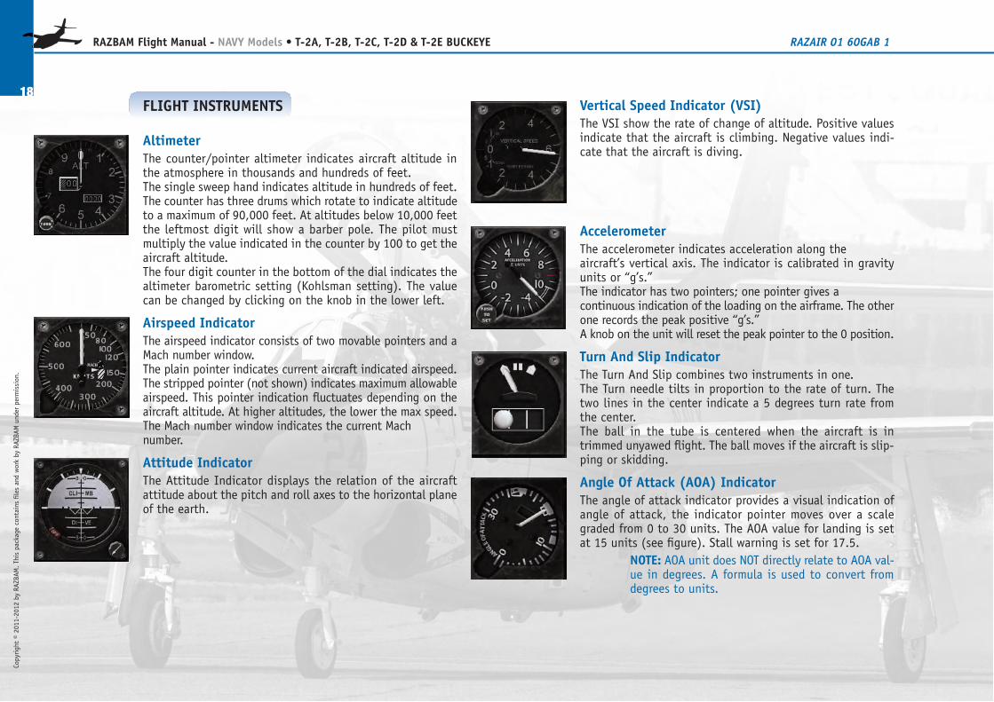
Vertical Speed Indicator (VSI)The VSI show the rate of change of altitude. Positive valuesindicate that the aircraft is climbing. Negative values indi-cate that the aircraft is diving.
AccelerometerThe accelerometer indicates acceleration along theaircraft’s vertical axis. The indicator is calibrated in gravityunits or “g’s.”The indicator has two pointers; one pointer gives acontinuous indication of the loading on the airframe. The otherone records the peak positive “g’s.”A knob on the unit will reset the peak pointer to the 0 position.
Turn�And�Slip IndicatorThe Turn�And�Slip combines two instruments in one.The Turn needle tilts in proportion to the rate of turn. Thetwo lines in the center indicate a 5 degrees turn rate fromthe center.The ball in the tube is centered when the aircraft is intrimmed unyawed flight. The ball moves if the aircraft is slip-ping or skidding.
Angle�Of�Attack (AOA) IndicatorThe angle�of�attack indicator provides a visual indication ofangle of attack, the indicator pointer moves over a scalegraded from 0 to 30 units. The AOA value for landing is setat 15 units (see figure). Stall warning is set for 17.5.
NOTE: AOA unit does NOT directly relate to AOA val-ue in degrees. A formula is used to convert fromdegrees to units.
18
RAZBAM Flight Manual - NAVY Models • T-2A, T-2B, T-2C, T-2D & T-2E BUCKEYE RAZAIR�01�60GAB�1
Copyright © 2011-2012 by RAZBAM
. This package contains files and work by RAZBAM under permission.
FLIGHT INSTRUMENTS
AltimeterThe counter/pointer altimeter indicates aircraft altitude inthe atmosphere in thousands and hundreds of feet.The single sweep hand indicates altitude in hundreds of feet.The counter has three drums which rotate to indicate altitudeto a maximum of 90,000 feet. At altitudes below 10,000 feetthe leftmost digit will show a barber pole. The pilot mustmultiply the value indicated in the counter by 100 to get theaircraft altitude.The four digit counter in the bottom of the dial indicates thealtimeter barometric setting (Kohlsman setting). The valuecan be changed by clicking on the knob in the lower left.
Airspeed IndicatorThe airspeed indicator consists of two movable pointers and aMach number window.The plain pointer indicates current aircraft indicated airspeed.The stripped pointer (not shown) indicates maximum allowableairspeed. This pointer indication fluctuates depending on theaircraft altitude. At higher altitudes, the lower the max speed.The Mach number window indicates the current Machnumber.
Attitude IndicatorThe Attitude Indicator displays the relation of the aircraftattitude about the pitch and roll axes to the horizontal planeof the earth.
Copyright © 2011-2012 by RAZBAM
. This package contains files and work by RAZBAM under permission.
19
RAZBAM Flight Manual - NAVY Models • T-2A, T-2B, T-2C, T-2D & T-2E BUCKEYE RAZAIR�01�60GAB�1
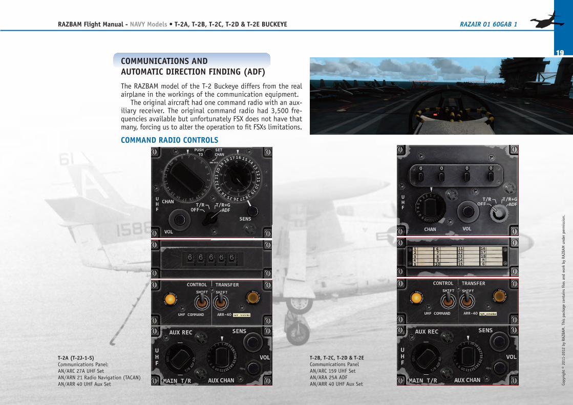
COMMUNICATIONS ANDAUTOMATIC DIRECTION FINDING (ADF)
The RAZBAM model of the T-2 Buckeye differs from the realairplane in the workings of the communication equipment.
The original aircraft had one command radio with an aux-iliary receiver. The original command radio had 3,500 fre-quencies available but unfortunately FSX does not have thatmany, forcing us to alter the operation to fit FSXs limitations.
COMMAND RADIO CONTROLS
T-2A (T-2J-1-S)Communications Panel:AN/ARC�27A UHF SetAN/ARN�21 Radio Navigation (TACAN)AN/ARR�40 UHF Aux Set
T-2B, T-2C, T-2D & T-2ECommunications PanelAN/ARC�159 UHF SetAN/ARA�25A ADFAN/ARR�40 UHF Aux Set
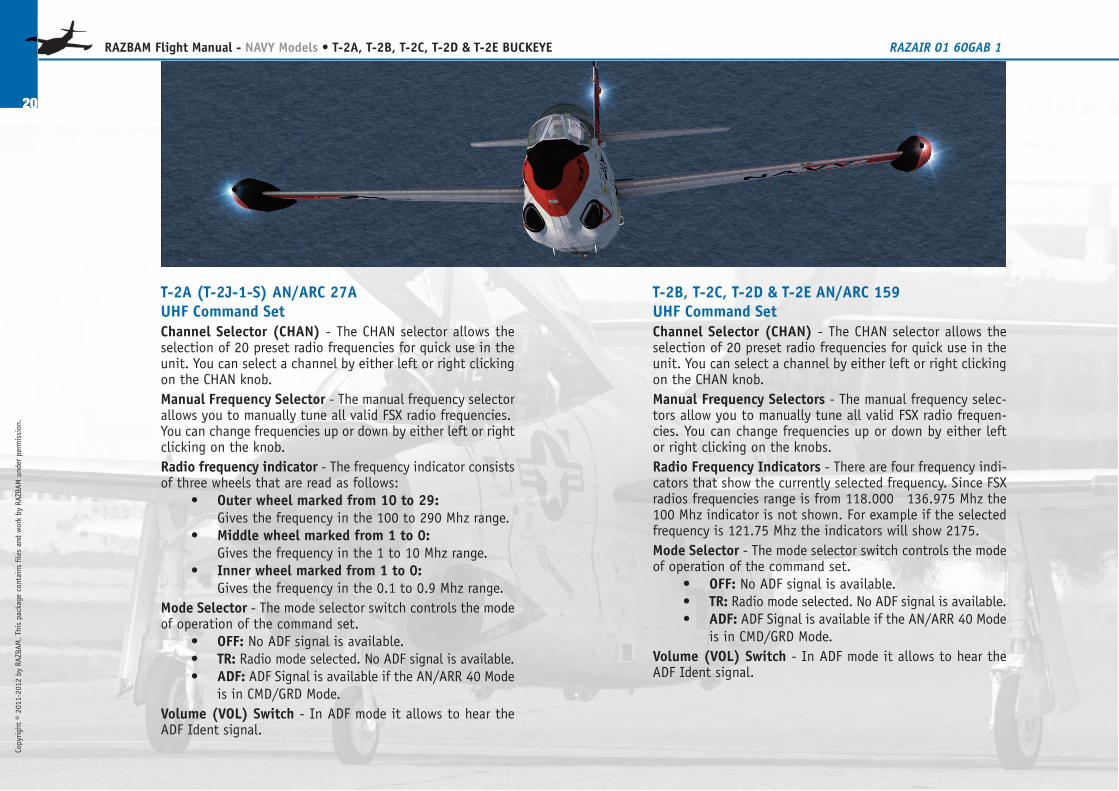
T-2B, T-2C, T-2D & T-2E AN/ARC�159UHF Command SetChannel Selector (CHAN) - The CHAN selector allows theselection of 20 preset radio frequencies for quick use in theunit. You can select a channel by either left or right clickingon the CHAN knob.Manual Frequency Selectors - The manual frequency selec-tors allow you to manually tune all valid FSX radio frequen-cies. You can change frequencies up or down by either leftor right clicking on the knobs.Radio Frequency Indicators - There are four frequency indi-cators that show the currently selected frequency. Since FSXradios frequencies range is from 118.000 � 136.975 Mhz the100 Mhz indicator is not shown. For example if the selectedfrequency is 121.75 Mhz the indicators will show 2175.Mode Selector - The mode selector switch controls the modeof operation of the command set.
• OFF: No ADF signal is available.• TR: Radio mode selected. No ADF signal is available.• ADF: ADF Signal is available if the AN/ARR�40 Mode
is in CMD/GRD Mode.Volume (VOL) Switch - In ADF mode it allows to hear theADF Ident signal.
T-2A (T-2J-1-S) AN/ARC�27AUHF Command SetChannel Selector (CHAN) - The CHAN selector allows theselection of 20 preset radio frequencies for quick use in theunit. You can select a channel by either left or right clickingon the CHAN knob.Manual Frequency Selector - The manual frequency selectorallows you to manually tune all valid FSX radio frequencies.You can change frequencies up or down by either left or rightclicking on the knob.Radio frequency indicator - The frequency indicator consistsof three wheels that are read as follows:
• Outer wheel marked from 10 to 29:Gives the frequency in the 100 to 290 Mhz range.
• Middle wheel marked from 1 to 0:Gives the frequency in the 1 to 10 Mhz range.
• Inner wheel marked from 1 to 0:Gives the frequency in the 0.1 to 0.9 Mhz range.
Mode Selector - The mode selector switch controls the modeof operation of the command set.
• OFF: No ADF signal is available.• TR: Radio mode selected. No ADF signal is available.• ADF: ADF Signal is available if the AN/ARR�40 Mode
is in CMD/GRD Mode.Volume (VOL) Switch - In ADF mode it allows to hear theADF Ident signal.
20
RAZBAM Flight Manual - NAVY Models • T-2A, T-2B, T-2C, T-2D & T-2E BUCKEYE RAZAIR�01�60GAB�1
Copyright © 2011-2012 by RAZBAM
. This package contains files and work by RAZBAM under permission.
Copyright © 2011-2012 by RAZBAM
. This package contains files and work by RAZBAM under permission.
21
RAZBAM Flight Manual - NAVY Models • T-2A, T-2B, T-2C, T-2D & T-2E BUCKEYE RAZAIR�01�60GAB�1
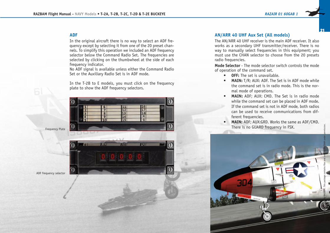
AN/ARR�40 UHF Aux Set (All models)The AN/ARR�40 UHF receiver is the main ADF receiver. It alsoworks as a secondary UHF transmitter/receiver. There is noway to manually select frequencies in this equipment; youmust use the CHAN selector to choose from the 20 presetsradio frequencies.Mode Selector - The mode selector switch controls the modeof operation of the command set.
• OFF: The set is unavailable.• MAIN: T/R; AUX: ADF. The Set is in ADF mode while
the command set is in radio mode. This is the nor-mal mode of operations.
• MAIN: ADF; AUX: CMD. The Set is in radio modewhile the command set can be placed in ADF mode.If the command set is not in ADF mode, both radioscan be used to receive communications from dif-ferent frequencies.
• MAIN: ADF; AUX:GRD. Works the same as ADF/CMD.There is no GUARD frequency in FSX.
ADFIn the original aircraft there is no way to select an ADF fre-quency except by selecting it from one of the 20 preset chan-nels. To simplify this operation we included an ADF frequencyselector below the Command Radio Set. The frequencies areselected by clicking on the thumbwheel at the side of eachfrequency indicator.No ADF signal is available unless either the Command RadioSet or the Auxiliary Radio Set is in ADF mode.
In the T-2B to E models, you must click on the frequencyplate to show the ADF frequency selectors.
Frequency Plate
ADF frequency selector
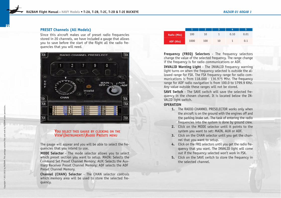
Frequency (FREQ) Selectors - The frequency selectorschange the value of the selected frequency. The range changeif the frequency is for radio communications or ADF.INVALID Warning Light - The INVALID frequency warninglight turns on when the frequency selected is outside the al-lowed range for FSX. The FSX frequency range for radio com-munications is from 118.000 - 136.975 Mhz. The frequencyrange for ADF radio navigation is from 100.0 to 1799.9 KHz.Any value outside these ranges will not be stored.SAVE Switch - The SAVE switch will save the selected fre-quency in the chosen channel. It is located below the IN-VALID light switch.OPERATION
1. The RADIO CHANNEL PRESELECTOR works only whenthe aircraft is on the ground with the engines off andthe parking brake set. The task of entering the radiofrequencies into the system is done by ground crew.
2. Click on the MODE selector until it points to thesystem you want to set: MAIN, AUX or ADF.
3. Click on the CHAN selector until you get the chan-nel that you want to setup.
4. Click on the FRQ selectors until you get the radio fre-quency that you want. The INVALID light will comeout if the frequency selected won’t work in FSX.
5. Click on the SAVE switch to store the frequency inthe selected channel.
PRESET Channels (All Models)Since this aircraft makes use of preset radio frequenciesstored in 20 channels, we have included a gauge that allowsyou to save before the start of the flight all the radio fre-quencies that you will need.
YOU SELECT THIS GAUGE BY CLICKING ON THEVIEW\INSTRUMENTS\RADIO PRESETS MENU
The gauge will appear and you will be able to select the fre-quencies that you intend to use.MODE Selector - The mode selector allows you to selectwhich preset section you want to setup. MAIN: Selects theCommand Set Preset Channel Memory; AUX: Selects the Aux-iliary Receiver Preset Channel Memory; ADF selects the ADFPreset Channel Memory.Channel (CHAN) Selector - The CHAN selector controlswhich memory area will be used to store the selected fre-quency.
22
RAZBAM Flight Manual - NAVY Models • T-2A, T-2B, T-2C, T-2D & T-2E BUCKEYE RAZAIR�01�60GAB�1
Copyright © 2011-2012 by RAZBAM
. This package contains files and work by RAZBAM under permission.
1 2 3 4 5
Radio (Mhz) 100 10 1 0.10 0.01
ADF (Khz) 1000 100 10 1 0.1
Copyright © 2011-2012 by RAZBAM
. This package contains files and work by RAZBAM under permission.
23
RAZBAM Flight Manual - NAVY Models • T-2A, T-2B, T-2C, T-2D & T-2E BUCKEYE RAZAIR�01�60GAB�1
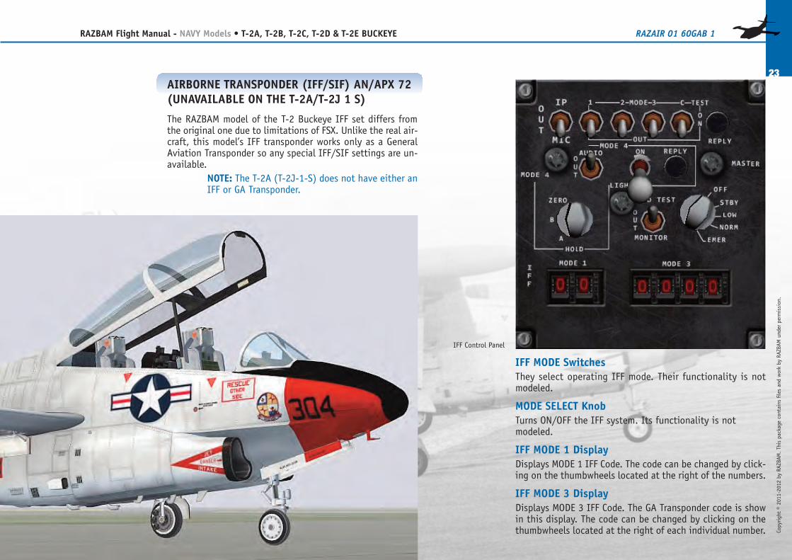
IFF MODE SwitchesThey select operating IFF mode. Their functionality is notmodeled.
MODE SELECT KnobTurns ON/OFF the IFF system. Its functionality is notmodeled.
IFF MODE 1 DisplayDisplays MODE 1 IFF Code. The code can be changed by click-ing on the thumbwheels located at the right of the numbers.
IFF MODE 3 DisplayDisplays MODE 3 IFF Code. The GA Transponder code is showin this display. The code can be changed by clicking on thethumbwheels located at the right of each individual number.
AIRBORNE TRANSPONDER (IFF/SIF) AN/APX�72(UNAVAILABLE ON THE T-2A/T-2J�1�S)
The RAZBAM model of the T-2 Buckeye IFF set differs fromthe original one due to limitations of FSX. Unlike the real air-craft, this model’s IFF transponder works only as a GeneralAviation Transponder so any special IFF/SIF settings are un-available.
NOTE: The T-2A (T-2J-1-S) does not have either anIFF or GA Transponder.
IFF Control Panel
T-2A (T-2-J-1-S)Westinghouse J34-WE-46/48 ENGINE OPERATIONAL LIMITS
Oil Pressure...................................40 - 50 PSIHydraulic Pressure .........................3100 PSIEngine speed
Normal (maximum continuous) ...96.8% RPMMilitary (30 minutes)................101% RPMOverspeed (20 seconds) ............104% RPM
Exhaust Gas TemperatureNormal (maximum continuous) ...905°CMilitary (30 minutes)................960°COvertemperature (20 seconds) > .960°C
MAXIMUM OPERATING WEIGHTSField Operations
Take off ..................................11,528 lbsLanding ..................................9,915 lbsArrested landing ......................9,915 lbs
(no tip�tank fuel)Carrier Operations
Catapult .................................11,369 lbsArrested Landing......................9,915 lbs
(no tip�tank fuel)
24
RAZBAM Flight Manual - NAVY Models • T-2A, T-2B, T-2C, T-2D & T-2E BUCKEYE RAZAIR�01�60GAB�1
Copyright © 2011-2012 by RAZBAM
. This package contains files and work by RAZBAM under permission.
AIRCRAFT OPERATING LIMITATIONS
We at RAZBAM have worked to provide you with the most accu-rate simulation of a real T-2 Buckeye. Because of that, and justlike the real aircraft, there are several operating limitations thatyou must keep in mind to avoid crashing and burning.
Note: The flight model is very close to the real one.Do not exceed these limitations or you will findyourself in real trouble real fast.
CAUTION: THE RISK OF OVERHEATING THEENGINE IS REAL. PAY CLOSE ATTENTION TO THEEGT GAUGE, ESPECIALLY WHEN USING 100%THROTTLE OR WHEN DIVING. REFRAIN FROMUSING POWER DIVES UNLESS ABSOLUTELYNECESSARY. ENGINE DAMAGE WILL OCCUR IFTHE OVERTEMPERATURE CONDITION REMAINSTOO LONG.
MAXIMUM PERMISSIBLE AIRSPEEDSAirspeed .......................................485 KIAS from sea
level to 9,000 feet....................................................0.85 MACH above
9,000 feet.Flaps
Normal actuation (in transit) .....165 KIASExtended ................................165 KIAS
Landing GearNormal actuation (in transit) .....165 KIASExtended ................................165 KIAS
Copyright © 2011-2012 by RAZBAM
. This package contains files and work by RAZBAM under permission.
25
RAZBAM Flight Manual - NAVY Models • T-2A, T-2B, T-2C, T-2D & T-2E BUCKEYE RAZAIR�01�60GAB�1
T-2C, T-2D & T-2EGeneral Electric J85-GE-4 ENGINE OPERATIONAL LIMITS
Oil Pressure...................................40 - 50 PSIHydraulic Pressure .........................3100 PSIEngine speed
Normal (maximum continuous) ...96.8% RPMMilitary (30 minutes)................101% RPMOverspeed (20 seconds) ............104% RPM
Exhaust Gas TemperatureNormal (maximum continuous) ...718°CMilitary (30 minutes)................732°COvertemperature (20 seconds) > .732°C
MAXIMUM OPERATING WEIGHTSField Operations
Take off ..................................14,000 lbsLanding ..................................14,000 lbsArrested landing ......................12,445 lbs
(no tip�tank fuel)Carrier Operations
Catapult .................................14,000 lbsArrested Landing......................12,000 lbs
(no tip�tank fuel)
CAUTION: FOLLOW THESE LIMITATIONS,ESPECIALLY WHEN LANDING. THE AIRCRAFTCAN AND WILL DEPART FROM CONTROLLEDFLIGHT IF YOU DON’T FOLLOW THEM.
T-2BPratt & Whitney J60-P-6 ENGINE OPERATIONAL LIMITS
Oil Pressure...................................40 – 50 PSIHydraulic Pressure .........................3100 PSIEngine speed
Normal (maximum continuous) ...96.8% RPMcontinuous.
Military (30 minutes)................104.2% RPMOverspeed (20 seconds) ............106%
Exhaust Gas TemperatureNormal (maximum continuous) ...577°CMilitary (30 minutes)................677°COvertemperature (20 seconds) > .677°C
MAXIMUM OPERATING WEIGHTSField Operations
Take off ..................................13,300 lbsLanding ..................................13,300 lbsArrested landing ......................10,400 lbs
(no tip�tank fuel)Carrier Operations
Catapult .................................13,300 lbsArrested Landing......................10,400 lbs
(no tip�tank fuel)
26
RAZBAM Flight Manual - NAVY Models • T-2A, T-2B, T-2C, T-2D & T-2E BUCKEYE RAZAIR�01�60GAB�1
Copyright © 2011-2012 by RAZBAM
. This package contains files and work by RAZBAM under permission.
Fig. 1Normal “Cluttered” view
Fig 2“Uncluttered” view
NAVIGATION/WEAPONS DELIVERY SYSTEM
The Navigation/Weapons Delivery system assists the pilot innavigation and weapons release. The instruments here de-tailed work as close as possible to the originals.
Note: Several instruments panels are “hidden” byother elements like the throttle, pilot’s joystick andlevers. To “clear the clutter” we have set up aswitch in the INTERNAL LIGHTS panel to makethese elements appear/disappear.
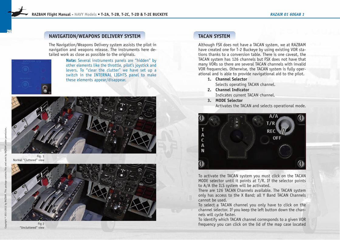
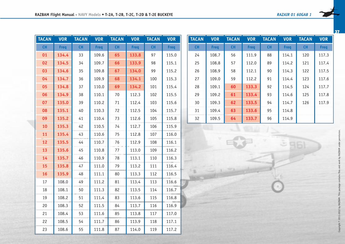
TACAN SYSTEM
Although FSX does not have a TACAN system, we at RAZBAMhave created one for T-2 Buckeye by using existing VOR sta-tions thanks to a conversion table. There is one caveat, theTACAN system has 126 channels but FSX does not have thatmany VORs so there are several TACAN channels with invalidVOR frequencies. Otherwise, the TACAN system is fully oper-ational and is able to provide navigational aid to the pilot.
1. Channel SelectorSelects operating TACAN channel.
2. Channel IndicatorIndicates current TACAN channel.
3. MODE SelectorActivates the TACAN and selects operational mode.
To activate the TACAN system you must click on the TACANMODE selector until it points at T/R. If the selector pointsto A/A the ILS system will be activated.There are 126 TACAN Channels available. The TACAN systemonly has access to the X Band; all Y Band TACAN Channelscannot be used.To select a TACAN channel you only have to click on thechannel selector. If you keep the left button down the chan-nels will cycle faster.To identify which TACAN channel corresponds to a given VORfrequency you can click on the lid of the map case located
Copyright © 2011-2012 by RAZBAM
. This package contains files and work by RAZBAM under permission.
27
RAZBAM Flight Manual - NAVY Models • T-2A, T-2B, T-2C, T-2D & T-2E BUCKEYE RAZAIR�01�60GAB�1
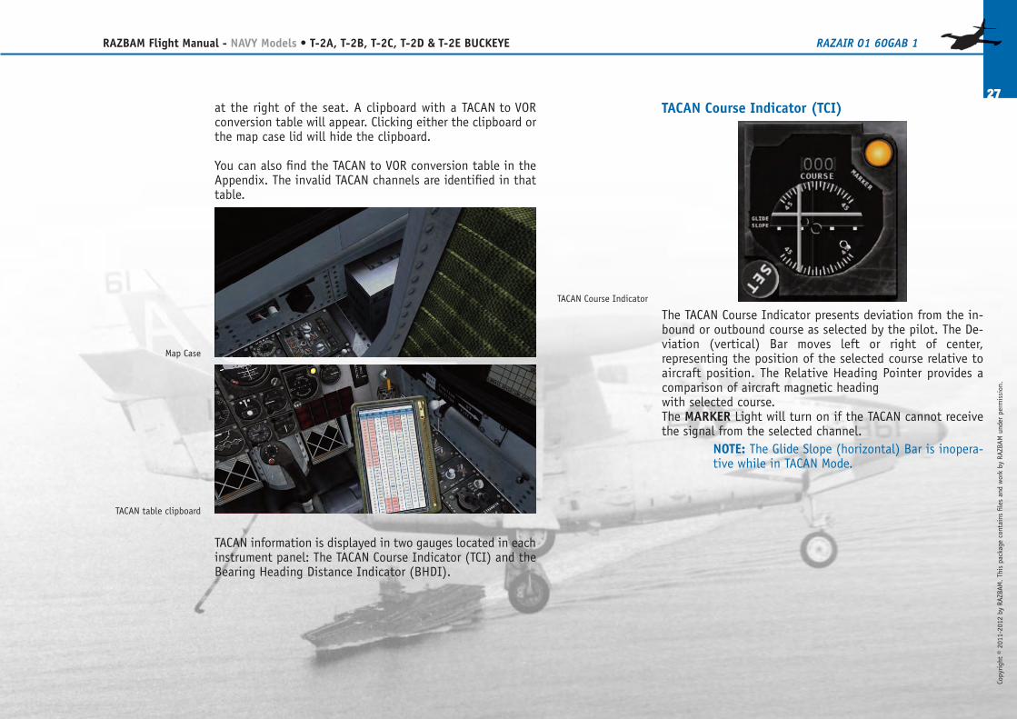
TACAN Course Indicator (TCI)
The TACAN Course Indicator presents deviation from the in-bound or outbound course as selected by the pilot. The De-viation (vertical) Bar moves left or right of center,representing the position of the selected course relative toaircraft position. The Relative Heading Pointer provides acomparison of aircraft magnetic headingwith selected course.The MARKER Light will turn on if the TACAN cannot receivethe signal from the selected channel.
NOTE: The Glide Slope (horizontal) Bar is inopera-tive while in TACAN Mode.
at the right of the seat. A clipboard with a TACAN�to�VORconversion table will appear. Clicking either the clipboard orthe map case lid will hide the clipboard.
You can also find the TACAN to VOR conversion table in theAppendix. The invalid TACAN channels are identified in thattable.
TACAN information is displayed in two gauges located in eachinstrument panel: The TACAN Course Indicator (TCI) and theBearing�Heading�Distance Indicator (BHDI).
Map Case
TACAN table clipboard
TACAN Course Indicator
OPERATIONTo operate the TACAN proceed as follows:
1. Click on the TACAN MODE Selector knob until itreads T/R.
2. Select desired TACAN station channel (1 to 126)by clicking on the CHAN selector switch.
3. Check MARKER light to see if a signal is being re-ceived. The light must remain off.
4. Check No. 2 bearing pointer needle and verifythat it is pointing.
5. Select desired course by clicking on the SET knob.6. Maneuver the aircraft until the Deviation Bar is
centered on the TCI.
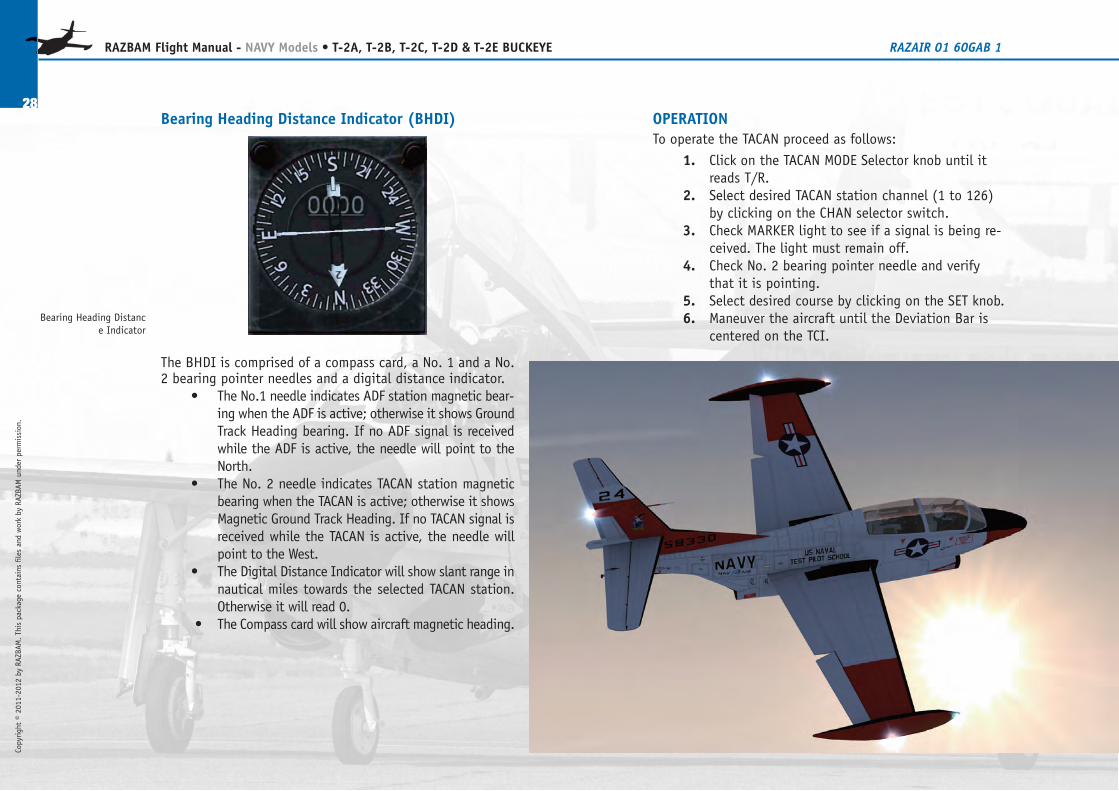
Bearing�Heading�Distance Indicator (BHDI)
The BHDI is comprised of a compass card, a No. 1 and a No.2 bearing pointer needles and a digital distance indicator.
• The No.1 needle indicates ADF station magnetic bear-ing when the ADF is active; otherwise it shows GroundTrack Heading bearing. If no ADF signal is receivedwhile the ADF is active, the needle will point to theNorth.
• The No. 2 needle indicates TACAN station magneticbearing when the TACAN is active; otherwise it showsMagnetic Ground Track Heading. If no TACAN signal isreceived while the TACAN is active, the needle willpoint to the West.
• The Digital Distance Indicator will show slant range innautical miles towards the selected TACAN station.Otherwise it will read 0.
�• The Compass card will show aircraft magnetic heading.
28
RAZBAM Flight Manual - NAVY Models • T-2A, T-2B, T-2C, T-2D & T-2E BUCKEYE RAZAIR�01�60GAB�1
Copyright © 2011-2012 by RAZBAM
. This package contains files and work by RAZBAM under permission.
Bearing�Heading�Distance Indicator
Copyright © 2011-2012 by RAZBAM
. This package contains files and work by RAZBAM under permission.
29
RAZBAM Flight Manual - NAVY Models • T-2A, T-2B, T-2C, T-2D & T-2E BUCKEYE RAZAIR�01�60GAB�1
OPERATIONTo operate the ILS you must proceed as follows:
1. Click on the TACAN MODE Selector knob until itreads A/A.
2. Select desired ILS frequency by clicking on the fre-quency selector knobs in the COMMAND SET.
3. Check the TCI, both the Deviation and Glide Slopebars should become active.
4. Maneuver the aircraft until the bars are centered inthe TCI.
NOTE: FSX ILS frequency ranges is from 108.000 to117.975 MHz. The 100 Mhz range value is not dis-played. An ILS frequency of 113.45 Mhz will be dis-played as 1345.
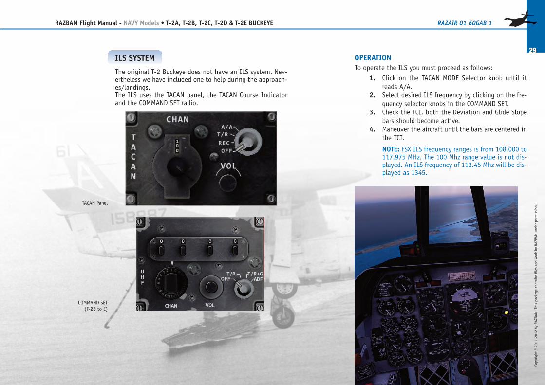
ILS SYSTEM
The original T-2 Buckeye does not have an ILS system. Nev-ertheless we have included one to help during the approach-es/landings.The ILS uses the TACAN panel, the TACAN Course Indicatorand the COMMAND SET radio.
TACAN Panel
COMMAND SET(T-2B to E)
30
RAZBAM Flight Manual - NAVY Models • T-2A, T-2B, T-2C, T-2D & T-2E BUCKEYE RAZAIR�01�60GAB�1
Copyright © 2011-2012 by RAZBAM
. This package contains files and work by RAZBAM under permission.
WEAPONS MANAGEMENT AND DELIVERY
The T-2 Buckeye was designed primarily to be a flight instruc-tion trainer. Nevertheless the aircraft could be configured tocarry a limited suite of weapons on two hard points. The T-2D and T-2E are an export version to which an armamentpackage that added four more hard points for a total of sixhave been installed.The aircraft could not carry mixed loads on the hard points;all hard point pairs load had to be the same.
▶ T-2A, T-2B and T-2C hard point pairs:1 – 2.
▶ T-2D and T-2E hard point pairs:1 – 6, 2 – 5 and 3 – 4.
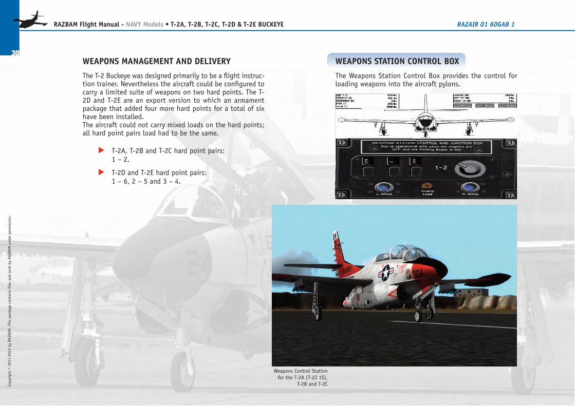
WEAPONS STATION CONTROL BOX
The Weapons Station Control Box provides the control forloading weapons into the aircraft pylons.
Weapons Control Stationfor the T-2A (T-2J�1S),
T-2B and T-2C
Copyright © 2011-2012 by RAZBAM
. This package contains files and work by RAZBAM under permission.
31
RAZBAM Flight Manual - NAVY Models • T-2A, T-2B, T-2C, T-2D & T-2E BUCKEYE RAZAIR�01�60GAB�1
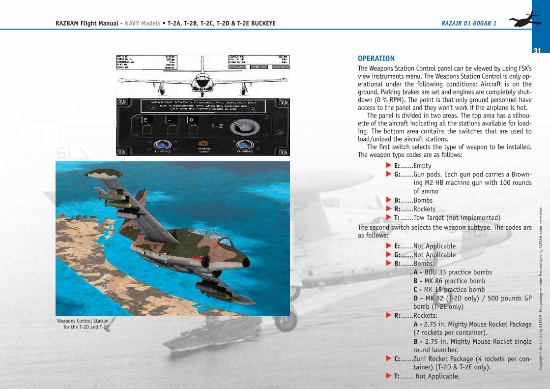
OPERATIONThe Weapons Station Control panel can be viewed by using FSX’sview instruments menu. The Weapons Station Control is only op-erational under the following conditions: Aircraft is on theground, Parking brakes are set and engines are completely shut-down (0 % RPM). The point is that only ground personnel haveaccess to the panel and they won’t work if the airplane is hot.
The panel is divided in two areas. The top area has a silhou-ette of the aircraft indicating all the stations available for load-ing. The bottom area contains the switches that are used toload/unload the aircraft stations.
The first switch selects the type of weapon to be installed.The weapon type codes are as follows:
▶ E: ......Empty▶ G:......Gun pods. Each gun pod carries a Brown-
ing M2 HB machine gun with 100 roundsof ammo
▶ B:......Bombs▶ R:......Rockets▶ T: ......Tow Target (not implemented)
The second switch selects the weapon subtype. The codes areas follows:
▶ E: ......Not Applicable▶ G:......Not Applicable▶ B:......Bombs:
A - BDU�33 practice bombsB - MK�86 practice bombC - MK�15 practice bombD - MK�82 (T-2D only) / 500 pounds GPbomb (T-2E only)
▶ R:......Rockets:A - 2.75 in. Mighty Mouse Rocket Package(7 rockets per container).B - 2.75 in. Mighty Mouse Rocket singleround launcher.
▶ C: ......Zuni Rocket Package (4 rockets per con-tainer) (T-2D & T-2E only).
▶ T: ...... Not Applicable.
Weapons Control Stationfor the T-2D and T-2E
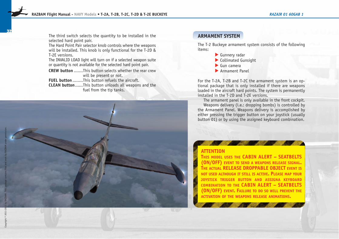
The third switch selects the quantity to be installed in theselected hard point pair.The Hard Point Pair selector knob controls where the weaponswill be installed. This knob is only functional for the T-2D &T-2E versions.The INVALID LOAD light will turn on if a selected weapon suiteor quantity is not available for the selected hard point pair.CREW button .......This button selects whether the rear crew
will be present or not.FUEL button ........This button refuels the aircraft.CLEAN button ......This button unloads all weapons and the
fuel from the tip tanks.
32
RAZBAM Flight Manual - NAVY Models • T-2A, T-2B, T-2C, T-2D & T-2E BUCKEYE RAZAIR�01�60GAB�1
Copyright © 2011-2012 by RAZBAM
. This package contains files and work by RAZBAM under permission.
ATTENTIONTHIS MODEL USES THE CABIN ALERT – SEATBELTS(ON/OFF) EVENT TO SEND A WEAPONS RELEASE SIGNAL.THE ACTUAL RELEASE DROPPABLE OBJECT EVENT ISNOT USED ALTHOUGH IT STILL IS ACTIVE. PLEASE MAP YOURJOYSTICK TRIGGER BUTTON AND ASSIGNA KEYBOARDCOMBINATION TO THE CABIN ALERT – SEATBELTS(ON/OFF) EVENT. FAILURE TO DO SO WILL PREVENT THEACTIVATION OF THE WEAPONS RELEASE ANIMATIONS.
ARMAMENT SYSTEM
The T-2 Buckeye armament system consists of the followingitems:
▶ Gunnery radar▶ Collimated Gunsight▶ Gun camera▶ Armament Panel
For the T-2A, T-2B and T-2C the armament system is an op-tional package that is only installed if there are weaponsloaded in the aircraft hard points. The system is permanentlyinstalled in the T-2D and T-2E versions.
The armament panel is only available in the front cockpit.Weapons delivery (i.e.: dropping bombs) is controlled by
the Armament Panel. Weapons delivery is accomplished byeither pressing the trigger button on your joystick (usuallybutton 01) or by using the assigned keyboard combination.
Copyright © 2011-2012 by RAZBAM
. This package contains files and work by RAZBAM under permission.
33
RAZBAM Flight Manual - NAVY Models • T-2A, T-2B, T-2C, T-2D & T-2E BUCKEYE RAZAIR�01�60GAB�1
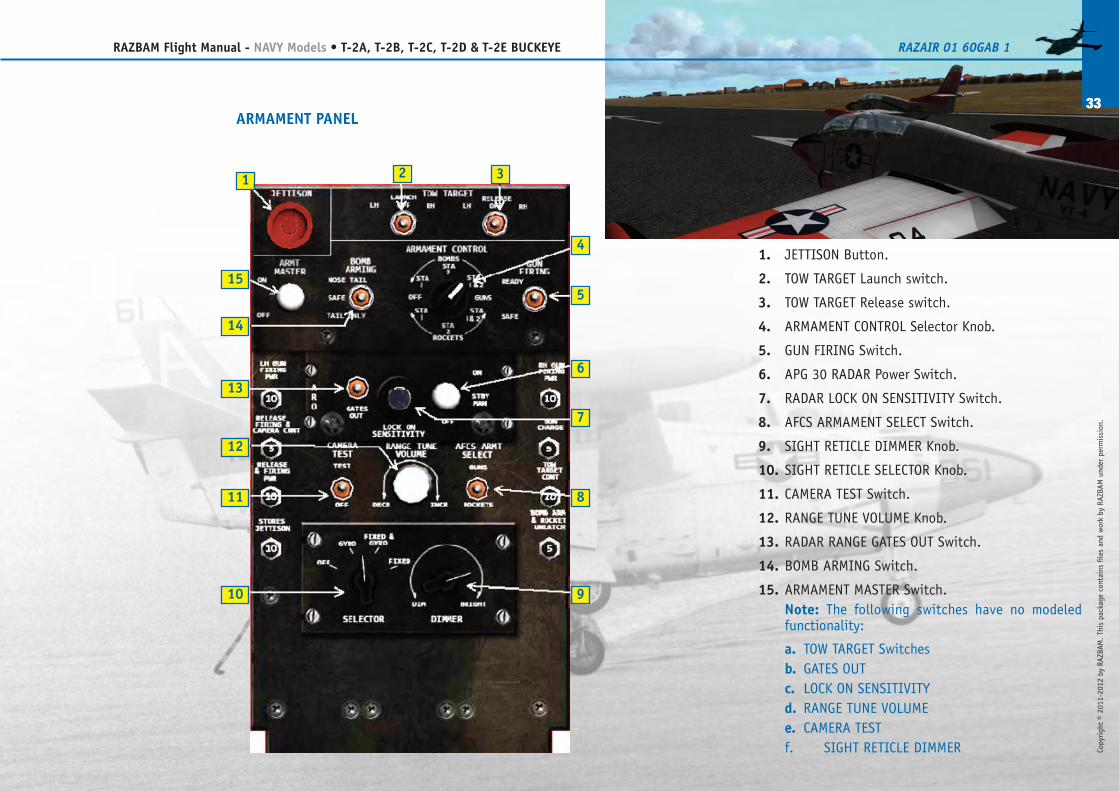
1. JETTISON Button.
2. TOW�TARGET Launch switch.
3. TOW�TARGET Release switch.
4. ARMAMENT CONTROL Selector Knob.
5. GUN FIRING Switch.
6. APG�30 RADAR Power Switch.
7. RADAR LOCK�ON SENSITIVITY Switch.
8. AFCS ARMAMENT SELECT Switch.
9. SIGHT RETICLE DIMMER Knob.
10. SIGHT RETICLE SELECTOR Knob.
11. CAMERA TEST Switch.
12. RANGE TUNE VOLUME Knob.
13. RADAR RANGE GATES�OUT Switch.
14. BOMB ARMING Switch.
15. ARMAMENT MASTER Switch.Note: The following switches have no modeledfunctionality:
a. TOW�TARGET Switchesb. GATES�OUTc. LOCK ON SENSITIVITYd. RANGE TUNE VOLUMEe. CAMERA TESTf. SIGHT RETICLE DIMMER
ARMAMENT PANEL
1 2
5
4
3
6
7
8
910
11
12
13
14
15
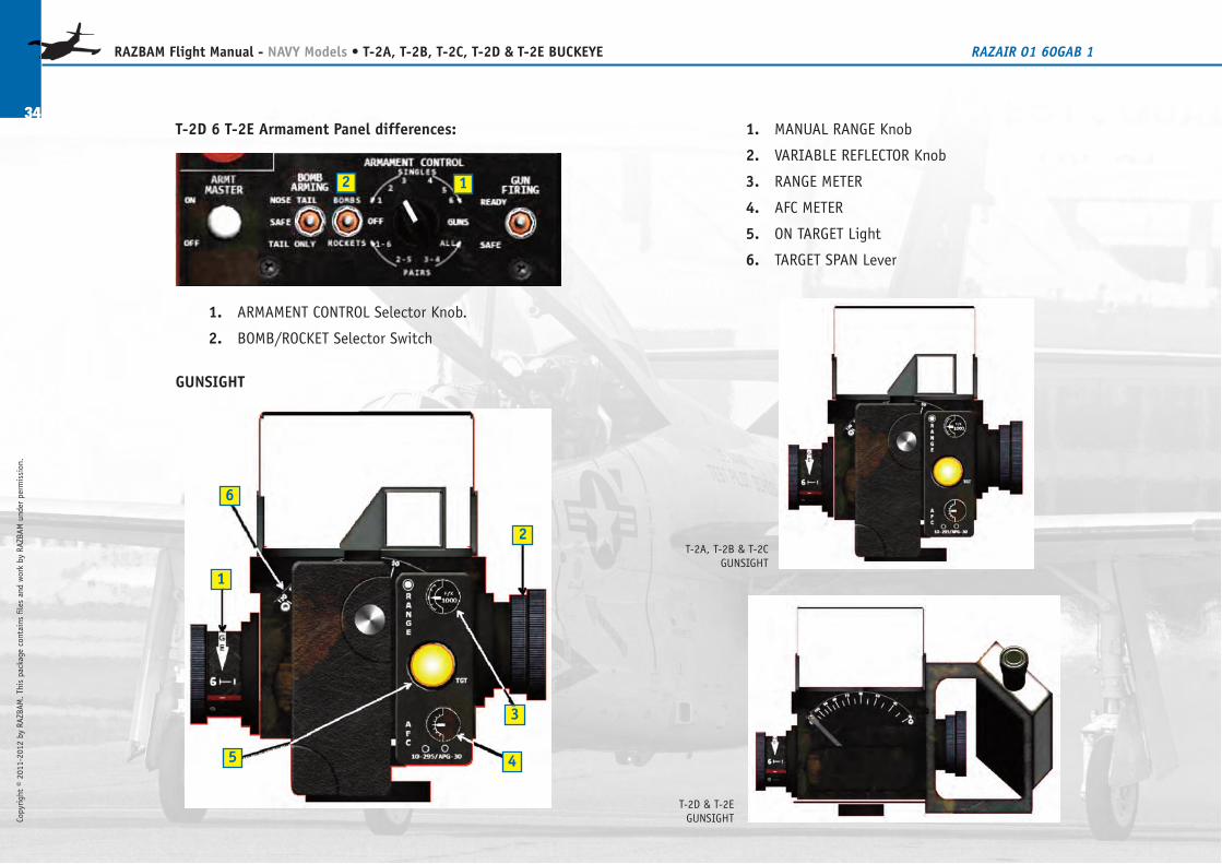
1. MANUAL RANGE Knob
2. VARIABLE REFLECTOR Knob
3. RANGE METER
4. AFC METER
5. ON�TARGET Light
6. TARGET SPAN Lever
T-2D 6 T-2E Armament Panel differences:
1. ARMAMENT CONTROL Selector Knob.
2. BOMB/ROCKET Selector Switch
GUNSIGHT
34
RAZBAM Flight Manual - NAVY Models • T-2A, T-2B, T-2C, T-2D & T-2E BUCKEYE RAZAIR�01�60GAB�1
Copyright © 2011-2012 by RAZBAM
. This package contains files and work by RAZBAM under permission.
T-2A, T-2B & T-2CGUNSIGHT
T-2D & T-2EGUNSIGHT
1
2
5 4
3
6
12
35
RAZBAM Flight Manual - NAVY Models • T-2A, T-2B, T-2C, T-2D & T-2E BUCKEYE RAZAIR�01�60GAB�1
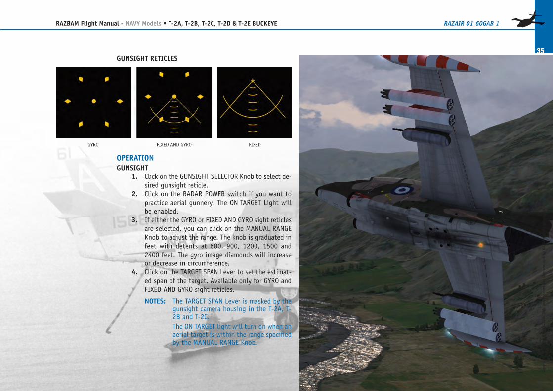
GUNSIGHT RETICLES
OPERATIONGUNSIGHT
1. Click on the GUNSIGHT SELECTOR Knob to select de-sired gunsight reticle.
2. Click on the RADAR POWER switch if you want topractice aerial gunnery. The ON�TARGET Light willbe enabled.
3. If either the GYRO or FIXED AND GYRO sight reticlesare selected, you can click on the MANUAL RANGEKnob to adjust the range. The knob is graduated infeet with detents at 600, 900, 1200, 1500 and2400 feet. The gyro image diamonds will increaseor decrease in circumference.
4. Click on the TARGET SPAN Lever to set the estimat-ed span of the target. Available only for GYRO andFIXED AND GYRO sight reticles.
NOTES: The TARGET SPAN Lever is masked by thegunsight camera housing in the T-2A, T-2B and T-2C.The ON TARGET light will turn on when anaerial target is within the range specifiedby the MANUAL RANGE Knob.
GYRO FIXED AND GYRO FIXED
Copyright © 2011-2012 by RAZBAM
. This package contains files and work by RAZBAM under permission.
36
RAZBAM Flight Manual - NAVY Models • T-2A, T-2B, T-2C, T-2D & T-2E BUCKEYE RAZAIR�01�60GAB�1
Copyright © 2011-2012 by RAZBAM
. This package contains files and work by RAZBAM under permission.
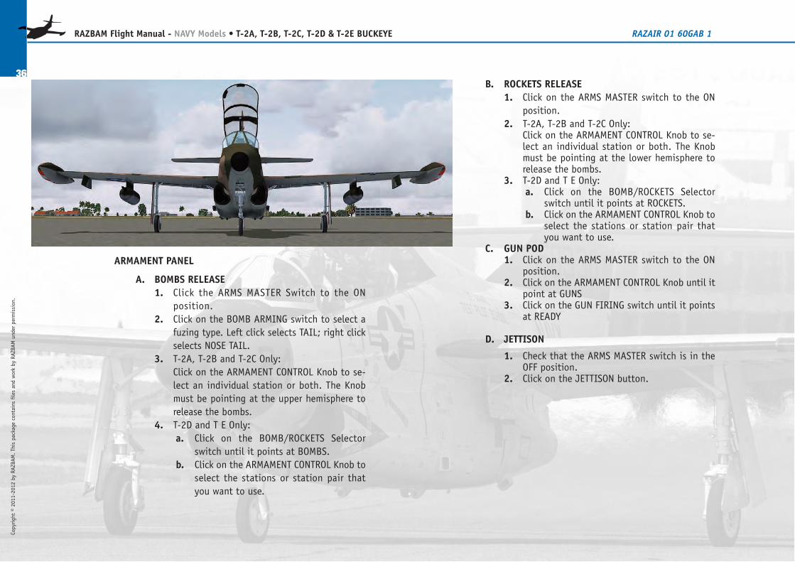
B. ROCKETS RELEASE1. Click on the ARMS MASTER switch to the ON
position.2. T-2A, T-2B and T-2C Only:
Click on the ARMAMENT CONTROL Knob to se-lect an individual station or both. The Knobmust be pointing at the lower hemisphere torelease the bombs.
3. T-2D and T�E Only:a. Click on the BOMB/ROCKETS Selector
switch until it points at ROCKETS.b. Click on the ARMAMENT CONTROL Knob to
select the stations or station pair thatyou want to use.
C. GUN POD1. Click on the ARMS MASTER switch to the ON
position.2. Click on the ARMAMENT CONTROL Knob until it
point at GUNS3. Click on the GUN FIRING switch until it points
at READY
D. JETTISON
1. Check that the ARMS MASTER switch is in theOFF position.
2. Click on the JETTISON button.
ARMAMENT PANEL
A. BOMBS RELEASE1. Click the ARMS MASTER Switch to the ON
position.2. Click on the BOMB ARMING switch to select a
fuzing type. Left click selects TAIL; right clickselects NOSE TAIL.
3. T-2A, T-2B and T-2C Only:Click on the ARMAMENT CONTROL Knob to se-lect an individual station or both. The Knobmust be pointing at the upper hemisphere torelease the bombs.
4. T-2D and T�E Only:a. Click on the BOMB/ROCKETS Selector
switch until it points at BOMBS.b. Click on the ARMAMENT CONTROL Knob to
select the stations or station pair thatyou want to use.
Copyright © 2011-2012 by RAZBAM
. This package contains files and work by RAZBAM under permission.
37
RAZBAM Flight Manual - NAVY Models • T-2A, T-2B, T-2C, T-2D & T-2E BUCKEYE RAZAIR�01�60GAB�1
TACAN VOR TACAN VOR TACAN VOR TACAN VOR
CH Freq CH Freq CH Freq CH Freq
01 134.4 33 109.6 65 133.8 97 115.0
02 134.5 34 109.7 66 133.9 98 115.1
03 134.6 35 109.8 67 134.0 99 115.2
04 134.7 36 109.9 68 134.1 100 115.3
05 134.8 37 110.0 69 134.2 101 115.4
06 134.9 38 110.1 70 112.3 102 115.5
07 135.0 39 110.2 71 112.4 103 115.6
08 135.1 40 110.3 72 112.5 104 115.7
09 135.2 41 110.4 73 112.6 105 115.8
10 135.3 42 110.5 74 112.7 106 115.9
11 135.4 43 110.6 75 112.8 107 116.0
12 135.5 44 110.7 76 112.9 108 116.1
13 135.6 45 110.8 77 113.0 109 116.2
14 135.7 46 110.9 78 113.1 110 116.3
15 135.8 47 111.0 79 113.2 111 116.4
16 135.9 48 111.1 80 113.3 112 116.5
17 108.0 49 111.2 81 113.4 113 116.6
18 108.1 50 111.3 82 113.5 114 116.7
19 108.2 51 111.4 83 113.6 115 116.8
20 108.3 52 111.5 84 113.7 116 116.9
21 108.4 53 111.6 85 113.8 117 117.0
22 108.5 54 111.7 86 113.9 118 117.1
23 108.6 55 111.8 87 114.0 119 117.2
TACAN VOR TACAN VOR TACAN VOR TACAN VOR
CH Freq CH Freq CH Freq CH Freq
24 108.7 56 111.9 88 114.1 120 117.3
25 108.8 57 112.0 89 114.2 121 117.4
26 108.9 58 112.1 90 114.3 122 117.5
27 109.0 59 112.2 91 114.4 123 117.6
28 109.1 60 133.3 92 114.5 124 117.7
29 109.2 61 133.4 93 114.6 125 117.8
30 109.3 62 133.5 94 114.7 126 117.9
31 109.4 63 133.6 95 114.8
32 109.5 64 133.7 96 114.9
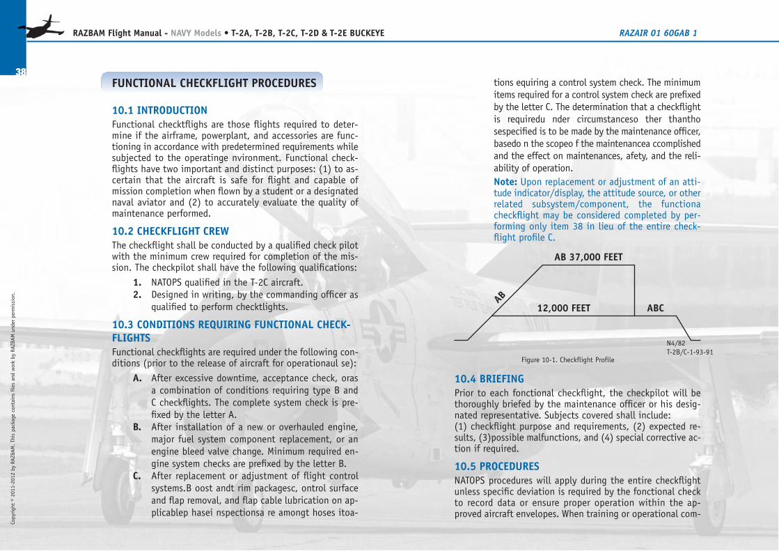
tions equiring a control system check. The minimumitems required for a control system check are prefixedby the letter C. The determination that a checkflightis requiredu nder circumstanceso ther thanthosespecified is to be made by the maintenance officer,basedo n the scopeo f the maintenancea ccomplishedand the effect on maintenances, afety, and the reli-ability of operation.Note: Upon replacement or adjustment of an atti-tude indicator/display, the attitude source, or otherrelated subsystem/component, the functionacheckflight may be considered completed by per-forming only item 38 in lieu of the entire check-flight profile C.
10.4 BRIEFINGPrior to each fonctional checkflight, the checkpilot will bethoroughly briefed by the maintenance officer or his desig-nated representative. Subjects covered shall include:(1) checkflight purpose and requirements, (2) expected re-sults, (3)possible malfunctions, and (4) special corrective ac-tion if required.
10.5 PROCEDURESNATOPS procedures will apply during the entire checkflightunless specific deviation is required by the fonctional checkto record data or ensure proper operation within the ap-proved aircraft envelopes. When training or operational com-
38
RAZBAM Flight Manual - NAVY Models • T-2A, T-2B, T-2C, T-2D & T-2E BUCKEYE RAZAIR�01�60GAB�1
Copyright © 2011-2012 by RAZBAM
. This package contains files and work by RAZBAM under permission.
AB 37,000 FEET
12,000 FEET ABC
AB
N4/82T-2B/C-1-93-91
Figure 10-1. Checkflight Profile
FUNCTIONAL CHECKFLIGHT PROCEDURES
10.1 INTRODUCTIONFunctional checktflighs are those flights required to deter-mine if the airframe, powerplant, and accessories are func-tioning in accordance with predetermined requirements whilesubjected to the operatinge nvironment. Functional check-flights have two important and distinct purposes: (1) to as-certain that the aircraft is safe for flight and capable ofmission completion when flown by a student or a designatednaval aviator and (2) to accurately evaluate the quality ofmaintenance performed.
10.2 CHECKFLIGHT CREWThe checkflight shall be conducted by a qualified check pilotwith the minimum crew required for completion of the mis-sion. The checkpilot shall have the following qualifications:
1. NATOPS qualified in the T-2C aircraft.2. Designed in writing, by the commanding officer as
qualified to perform checktlights.
10.3 CONDITIONS REQUIRING FUNCTIONAL CHECK-FLIGHTSFunctional checkflights are required under the following con-ditions (prior to the release of aircraft for operationaul se):
A. After excessive downtime, acceptance check, orasa combination of conditions requiring type B andC checkflights. The complete system check is pre-fixed by the letter A.
B. After installation of a new or overhauled engine,major fuel system component replacement, or anengine bleed valve change. Minimum required en-gine system checks are prefixed by the letter B.
C. After replacement or adjustment of flight controlsystems.B oost andt rim packagesc, ontrol surfaceand flap removal, and flap cable lubrication on ap-plicablep hasei nspectionsa re amongt hoses itoa-
Copyright © 2011-2012 by RAZBAM
. This package contains files and work by RAZBAM under permission.
39
RAZBAM Flight Manual - NAVY Models • T-2A, T-2B, T-2C, T-2D & T-2E BUCKEYE RAZAIR�01�60GAB�1
Preflight
1. .....Engines bays.
Check security of lines, quick-
disconnects, and doors.
2. .....Flap operation.
Check for loose panels and stop screw
adjustment.
3. .....Tailhook.
Drop tailhook; check proper operation
and pressure indication (raise after
ENGINE START).
4. .....Control surfaces.
Check full throw, cotter pins, and static
lines.
5. .....Trim operation.
Check trim operation, reset to neutral,
and observe alignment of tabs with
control surfaces.
6. .....Rear cockpit power control lever
release.
Check normal retraction and return to
IDLE stop.
PretAxi
7. .....Start aircrafi on battery
(22 volt minimum).
8. .....EGT inverter.
9. .....Engine performance.
Record engine instruments
at IDLE ‘pm:
a. EGT - 650°C Maximum.
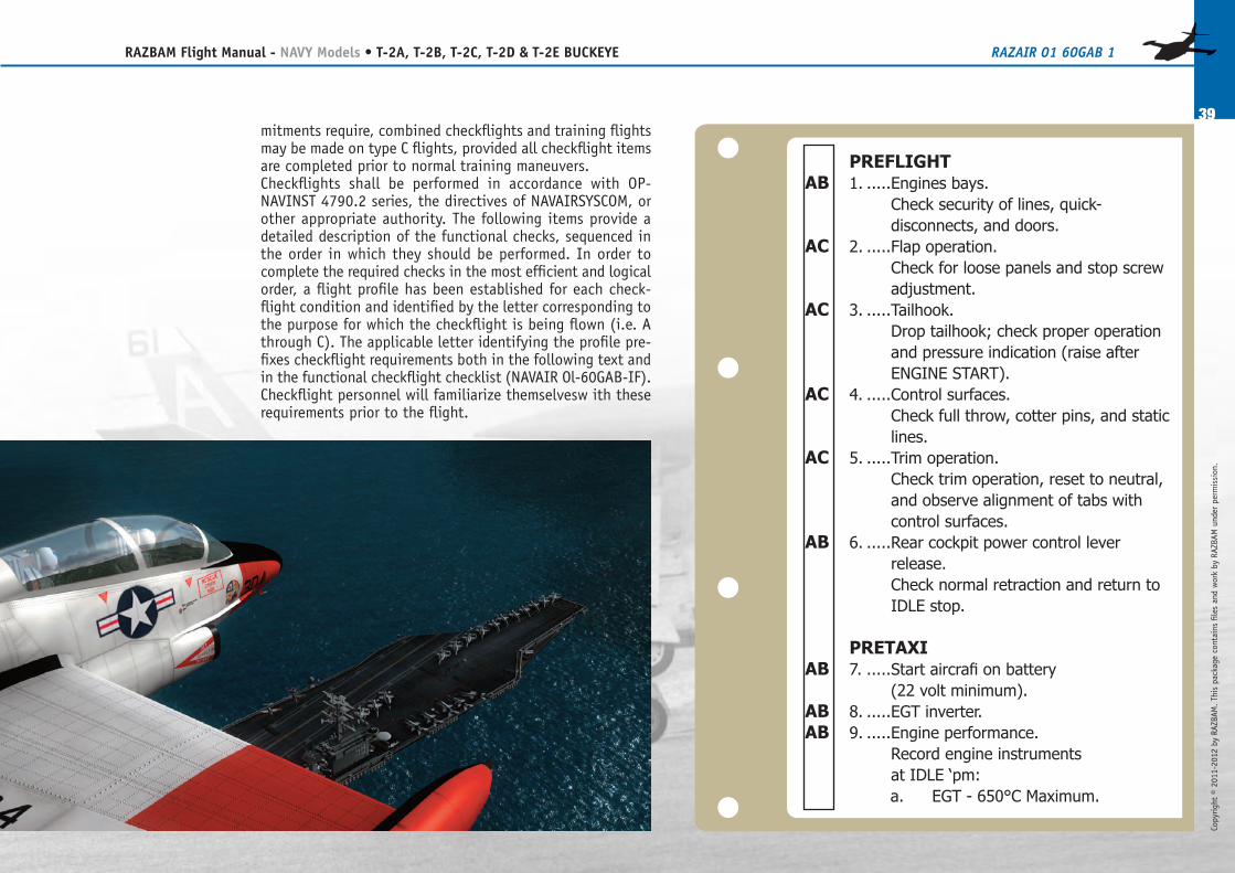
mitments require, combined checkflights and training flightsmay be made on type C flights, provided all checkflight itemsare completed prior to normal training maneuvers.Checkflights shall be performed in accordance with OP-NAVINST 4790.2 series, the directives of NAVAIRSYSCOM, orother appropriate authority. The following items provide adetailed description of the functional checks, sequenced inthe order in which they should be performed. In order tocomplete the required checks in the most efficient and logicalorder, a flight profile has been established for each check-flight condition and identified by the letter corresponding tothe purpose for which the checkflight is being flown (i.e. Athrough C). The applicable letter identifying the profile pre-fixes checkflight requirements both in the following text andin the functional checkflight checklist (NAVAIR Ol-60GAB-IF).Checkflight personnel will familiarize themselvesw ith theserequirements prior to the flight.
AB
AC
AC
AC
AC
AB
AB
AB
AB
40
RAZBAM Flight Manual - NAVY Models • T-2A, T-2B, T-2C, T-2D & T-2E BUCKEYE RAZAIR�01�60GAB�1
Copyright © 2011-2012 by RAZBAM
. This package contains files and work by RAZBAM under permission.
Prior to tuning on generators
after engine start, select No. 2
inverter and move power control
levers to check for EGT
indicating system operation.
Reselect No. 1 inverter and turn
on generators.
b. Rpm - 48.5 to 51.5 Percent.
Check both engines on battery
power only with the No. 2
inverter selected to ensure that
only rpm and EGT indicators are
functional.
c. Oil pressure- 5 Psi.
d. Fuel flow - 400 to 675 Pph.
e. Hydraulic pressure - 2,885 to
3,215 Psi.
10. ...External lights.
Check all external lights for operation.
tAxi
11. ...Brakes.
Check brakes for normal operation.
12. ...Basic Instrument Checklist.
Check for discrepancies.
13. ...Altimeter.
Record altimeter setting.
14. ...Runway temperature.
Record runway temperature.
tAkeoff
15. ...Acceleration check.
Record engine instruments at
maximum power prior to brake
release:
a. EGT - 732’C.
b. Rpm - 101.7 Percent.
c. PTs.
d. Fuel flow.
e. Oil pressure.
f. ENGINE ANTI-ICE switch.
At 95-percent rpm, check for PTs
drop with switch actuation,
return to OFF.
16. ...Landing gear.
Check gear retraction in 10 seconds
(maximum).
ClimB (AB - 37,000 feet, C - 12,000 feet)
17.....UHF.
Check UHF operation, squelch, preset,
and manual.
18. ...Engine performance.
Check engine instruments passing
10,000 feet, 270 KIAS:
a. Record EGT - 732 “C.
b. Record ‘pm - 101.7 Percent.
c. Oil pressure-Check 20 to 65 Psi.
d. Fuel flow-Check Split or
Fluctuation.
A
A
A
AB
AB
AB
A
A
AB
Copyright © 2011-2012 by RAZBAM
. This package contains files and work by RAZBAM under permission.
41
RAZBAM Flight Manual - NAVY Models • T-2A, T-2B, T-2C, T-2D & T-2E BUCKEYE RAZAIR�01�60GAB�1
e. Hydraulic pressure- Check 2,885
to 3,215 Psi.
f. Record cabin altitude (8,000
feet).
19. ...Inverters.
Select No. 2 and check for normal
indications; return to No. 1.
20. ...Tacan.
Check tacan and ID-249 for normal
operation on several channels.
21. ...Boost pump.
To checkb oost pump operation, pull
and reset boost pomp circuit breaker
individually noting change in
amperage loading.
22. ...Engine performance.
Check engine instruments, passing
20,000 feet, 240 KIAS:
a. Record EGT - 732 “C.
b. Record rpm - 101.7 Percent.
c. Oil pressure- Check 20 to 65 Psi.
d. Fuel flow - Check Split or
Fluctuation.
e. Hydraulic pressure-Check 2,885
to 3,215 Psi.
f. Record cabin altitude (8,000
feet).
g. ENGINE ANTI-ICE switch.
Select ON, check for PTs drop,
and leave ON.
23. ...Fuel dump.
Check fuel dump for equal operation
and secure.
24. ...IFF.
Check AN/APX-64 for normal operation
and IDENT.
25. ...AUXUHF.
Check AN/ARR-%O for normal
operation on available channels.
26. ...Engine performance.
Check engine instnunents, passing
30,000 feet, 215 KIAS:
a. Record EGT - 732 “C.
b. Record rpm - 101.7 Percent.
c. Oil pressure-C heck 20 to 65 Psi.
d. Fuel flow-check Split or
Fluctuation.
e. Hydraulic pressure- Check 2,885
to 3,215 Psi.
f. Record cabin altitude (11,500
feet).
27.....AIRSTART switches.
SelectO N, check for tone in headseta
t flight idle; rctmn to OFF.
28. ...CANOPY DEFROST switch.
SelectO N for 10 to 15 seconds;c heck
for sufficient warm airflow.
29. ...WINDSHIELD ANTI-ICE switch.
Check valve operationa nd slight
pressurizationc hange.
30. ...PITOT HEATER switch.
A
A
AB
AB
AB
A
A
AB
AB
A
A
A
42
RAZBAM Flight Manual - NAVY Models • T-2A, T-2B, T-2C, T-2D & T-2E BUCKEYE RAZAIR�01�60GAB�1
Copyright © 2011-2012 by RAZBAM
. This package contains files and work by RAZBAM under permission.
Cycle switch; check for variation in
amperagelo ading.
level (37,000 feet, 190 kiAS)
31. ...Engine Performance.
a. Record EGT - 732 “C.
b. Recordr pm - Maximum 9-
PercentD ecay, ‘I-PercentS plit.
c. Oil pressure- Check 20 to 65 Psi.
d. Fuel flow - Check Split or
Fluctuation.
e. Hydraulic pressure-Check 2,885
to 3,215 Psi.
f. Record cabin altitude (15,500
feet).
32. ...Compressor stall check.
Slow aircraft to 150 KIAS, wings level,
advance one power control lever to
maxinuun power.
Retard power control lever; jam
acceleratew hile engine is
decelerating.M onitor EGT and
airspeed,d o not slow below 150K IAS.
Repeatp rocedurew itb the otherp
ower control lever.
DeSCent to 12,000 feet
33. ...Generator.
Check generatore set and loading in
normal, operation for maximum 30-
ampere split.
34. ...Speedbrake.
a. Check speedbrake operation for
yaw (maximum one-ball-width
deflection) or hydraulic pressure
malfunction.
b. Pull speedbrake dump handle.
Checks peedbrakes IN. Resets
peedbrake dump handle and
cycle speedbrakes.
35. ...Engine checks.
a. Engine shutdown and airstart -
Check Individually.
b. Recordj am acceleration,fr om
IDLE to maximum power.
c. ENGINE ANTI-ICE switch-OFF.
level - 12,000 feet
36. ...Boost-off roll check.
a. Assure that the tip tanks have
equal amounts of fuel. Trim for
normal balanced flight at 200
ICIAS.
b. Activate trim disk or pull TRIM
CONTROL circuit breaker.
c. Secure HYD BOOST.
d. Cycle control stick briefly from
neutral position to relieve
residual hydraulicp ressure in the
flight control actuators.
AB
AB
A
AB
AB
AC
Copyright © 2011-2012 by RAZBAM
. This package contains files and work by RAZBAM under permission.
43
RAZBAM Flight Manual - NAVY Models • T-2A, T-2B, T-2C, T-2D & T-2E BUCKEYE RAZAIR�01�60GAB�1
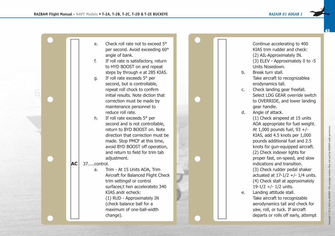
e. Check roll rate not to exceed 5°
per second. Avoid exceeding 60°
angle of bank.
f. If roll rate is satisfactory, return
to HYD BOOST on and repeat
steps by through e at 285 KIAS.
g. If roll rate exceeds 5° per
second, but is controllable,
repeat roll chock to confirm
initial results. Note diction that
correction must be made by
maintenance personnel to
reduce roll rate.
h. If roll rate exceeds 5° per
second and is not controllable,
return to BYD BOOST on. Note
direction that correction must be
made. Stop PMCF at this time,
avoid BYD BOOST off operation,
and return to field for trim tab
adjustment.
37.....control.
a. Trim - At 15 Units AOA, Trim
Aircraft for Balanced Flight Check
trim settingsf or control
surfaces;t hen accelerateto 340
KIAS andr echeck:
(1) RUD - Approximately IN
(check balance ball for a
maximum of one-ball-width
change).
Continue accelerating to 400
KIAS trim rudder and check:
(2) AIL-Approximately IN.
(3) ELEV - Approximately 0 to -5
Units Nosedown.
b. Break turn stall.
Take aircraft to recognizablea
erodynamics tall.
c. Check landing gear freefall.
Select LDG GEAR override switch
to OVERRIDE, and lower landing
gear handle.
d. Angle of attack.
(1) Check airspeed at 15 units
AOA appropriate for fuel weight.
At 1,000 pounds fuel, 93 +/-
KIAS, add 4.5 knots per 1,000
pounds additional fuel and 2.5
knots for gun-equipped aircraft.
(2) Check indexer lights for
proper fast, on-speed, and slow
indications and transition.
(3) Check rudder pedal shaker
actuated at 17-1/2 +/- 1/4 units.
(4) Check stall at approximately
19-1/2 +/- 1/2 units.
e. Landing attitude stall.
Take aircraft to recognizable
aerodynamics tall and check for
yaw, roll, or tuck. If aircraft
departs or rolls off early, attempt
AC
44
RAZBAM Flight Manual - NAVY Models • T-2A, T-2B, T-2C, T-2D & T-2E BUCKEYE RAZAIR�01�60GAB�1
Copyright © 2011-2012 by RAZBAM
. This package contains files and work by RAZBAM under permission.
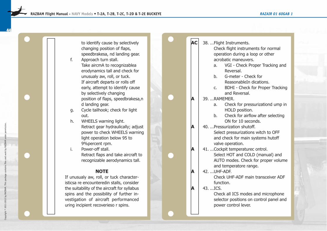
to identify cause by selectively
changing position of flaps,
speedbrakesa, nd landing gear.
f. Approach turn stall.
Take aircmA to recognizablea
erodynamics tall and check for
unusualy aw, roll, or tuck.
If aircraft departs or rolls off
early, attempt to identify cause
by selectively changing
position of flaps, speedbrakesa,n
d landing gear.
g. Cycle tailhook; check for light
out.
h. WHEELS warning light.
Retract gear hydraulically; adjust
power to check WHEELS warning
light operation below 95 to
9%percent rpm.
i. Power-off stall.
Retract flaps and take aircraft to
recognizable aerodynamics tall.
note
If unusualy aw, roll, or tuck character-
isticsa re encounteredin stalls, consider
the suitability of the aircraft for syllabus
spins and the possibility of further in-
vestigation of aircraft performanced
uring incipient recoverieso r spins.
38. ...Flight Instruments.
Check flight instruments for normal
operation during a loop or other
acrobatic maneuvers.
a. VGI - Check Proper Tracking and
Reversal.
b. G-meter - Check for
ReasonableIn dications.
c. BDHI - Check for Proper Tracking
and Reversal.
39. ...RAMEMER.
a. Check for pressurizationd ump in
HOLD position.
b. Check for airflow after selecting
ON for 10 seconds.
40. ...Pressurization shutoff.
Select pressurizations witch to OFF
and check for main systems hutoff
valve operation.
41. ...Cockpit temperaturec ontrol.
Select HOT and COLD (manual) and
AUTO modes. Check for proper volume
and temperatore range.
42. ...UHF-ADF.
Check UHF-ADF main transceiver ADF
function.
43. ...ICS.
Check all ICS modes and microphone
selector positions on control panel and
power control lever.
AC
A
A
A
A
A
Copyright © 2011-2012 by RAZBAM
. This package contains files and work by RAZBAM under permission.
45
RAZBAM Flight Manual - NAVY Models • T-2A, T-2B, T-2C, T-2D & T-2E BUCKEYE RAZAIR�01�60GAB�1
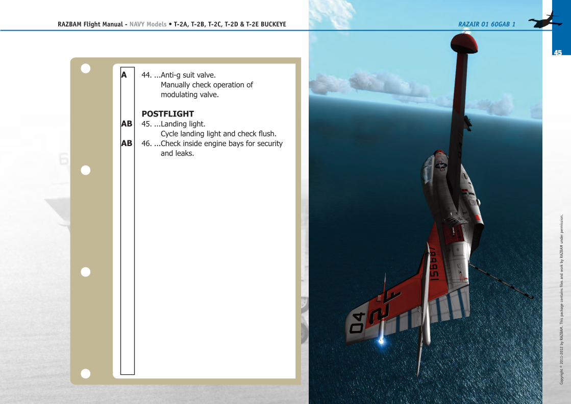
44. ...Anti-g suit valve.
Manually check operation of
modulating valve.
PoStflight
45. ...Landing light.
Cycle landing light and check flush.
46. ...Check inside engine bays for security
and leaks.
A
AB
AB
46
RAZBAM Flight Manual - NAVY Models • T-2A, T-2B, T-2C, T-2D & T-2E BUCKEYE RAZAIR�01�60GAB�1
Copyright © 2011-2012 by RAZBAM
. This package contains files and work by RAZBAM under permission.
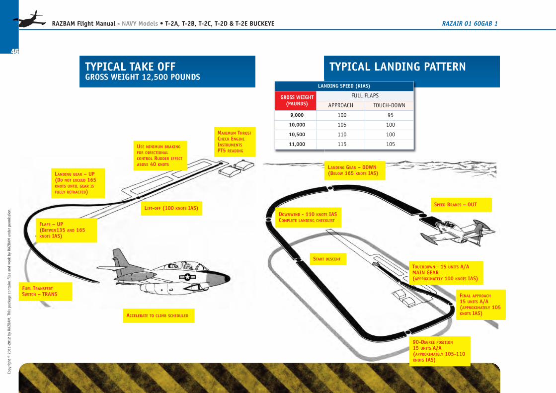
MAXIMUM THRUSTCHECK ENGINEINSTRUMENTSPT5 READING
TYPICAL TAKE OFFGROSS WEIGHT 12,500 POUNDS
TYPICAL LANDING PATTERN
USE MINIMUM BRAKINGFOR DIRECTIONALCONTROL RUDDER EFFECTABOVE 40 KNOTS
FLAPS – UP(BETWIN135 AND 165KNOTS IAS)
LANDING GEAR – UP(DO NOT EXCEED 165KNOTS UNTIL GEAR ISFULLY RETRACTED)
LIFT-OFF (100 KNOTS IAS)
ACCELERATE TO CLIMB SCHEDULED
FUEL TRANSFERTSWITCH – TRANS
SPEED BRAKES – OUT
LANDING GEAR – DOWN(BELOW 165 KNOTS IAS)
DOWNWIND - 110 KNOTS IASCOMPLETE LANDING CHECKLIST
START DESCENT
90-DEGREE POSITION15 UNITS A/A(APPROXIMATELY 105-110KNOTS IAS)
FINAL APPROACH15 UNITS A/A(APPROXIMATELY 105KNOTS IAS)
LANDING SPEED (KIAS)
GROSS WEIGHT(PAUNDS)
FULL FLAPS
APPROACH TOUCH-DOWN
9,000 100 95
10,000 105 100
10,500 110 100
11,000 115 105
TOUCHDOWN - 15 UNITS A/AMAIN GEAR(APPROXIMATELY 100 KNOTS IAS)
Copyright © 2011-2012 by RAZBAM
. This package contains files and work by RAZBAM under permission.
47
RAZBAM Flight Manual - NAVY Models • T-2A, T-2B, T-2C, T-2D & T-2E BUCKEYE RAZAIR�01�60GAB�1
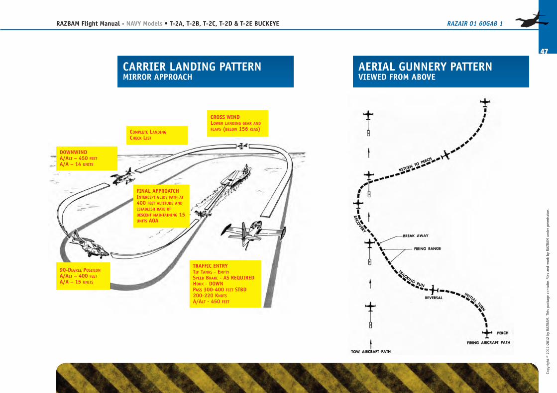
CARRIER LANDING PATTERNMIRROR APPROACH
AERIAL GUNNERY PATTERNVIEWED FROM ABOVE
CROSS WINDLOWER LANDING GEAR ANDFLAPS (BELOW 156 KIAS)COMPLETE LANDING
CHECK LIST
DOWNWINDA/ALT – 450 FEETA/A – 14 UNITS
90-DEGREE POSITIONA/ALT – 400 FEETA/A – 15 UNITS
FINAL APPROATCHINTERCEPT GLIDE PATH AT400 FEET ALTITUDE ANDESTABLISH RATE OFDESCENT MAINTAINING 15UNITS AOA
TRAFFIC ENTRYTIP TANKS - EMPTYSPEED BRAKE - AS REQUIREDHOOK - DOWNPASS 300-400 FEET STBD200-220 KNOTSA/ALT - 450 FEET
48
RAZBAM Flight Manual - NAVY Models • T-2A, T-2B, T-2C, T-2D & T-2E BUCKEYE RAZAIR�01�60GAB�1
Copyright © 2011-2012 by RAZBAM
. This package contains files and work by RAZBAM under permission.
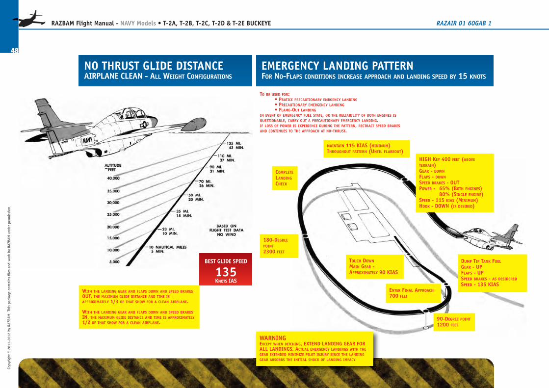
NO THRUST GLIDE DISTANCEAIRPLANE CLEAN - ALL WEIGHT CONFIGURATIONS
EMERGENCY LANDING PATTERNFOR NO-FLAPS CONDITIONS INCREASE APPROACH AND LANDING SPEED BY 15 KNOTS
BEST GLIDE SPEED
135KNOTS IAS
WITH THE LANDING GEAR AND FLAPS DOWN AND SPEED BRAKESOUT, THE MAXIMUM GLIDE DISTANCE AND TIME ISAPPROXIMATELY 1/3 OF THAT SHOW FOR A CLEAN AIRPLANE.
WITH THE LANDING GEAR AND FLAPS DOWN AND SPEED BRAKESIN, THE MAXIMUM GLIDE DISTANCE AND TIME IS APPROXIMATELY1/2 OF THAT SHOW FOR A CLEAN AIRPLANE.
TO BE USED FOR:• PRATICE PRECAUTIONARY EMRGENCY LANDING• PRECAUTIONARY EMERGENCY LANDING• FLAME-OUT LANDING
IN EVENT OF EMERGENCY FUEL STATE, OR THE RELIABILITY OF BOTH ENGINES ISQUESTIONABLE, CARRY OUT A PRECAUTIONARY EMERGENCY LANDING.IF LOSS OF POWER IS EXPERIENCE DURING THE PATTERN, RECTRACT SPEED BRAKESAND CONTINUES TO THE APPROACH AT NO-THRUST.
MAINTAIN 115 KIAS (MINIMUM)THROUGHOUT PATTERN (UNTIL FLAREOUT)
COMPLETELANDINGCHECK
180-DEGREEPOINT2300 FEET
90-DEGREE POINT1200 FEET
ENTER FINAL APPROACH700 FEET
TOUCH DOWNMAIN GEAR -APPROXIMATELY 90 KIAS
DUMP TIP TANK FUELGEAR - UPFLAPS - UPSPEED BRAKES - AS DESIDEREDSPEED - 135 KIAS
HIGH KEY 400 FEET (ABOVETERRAIN)GEAR - DOWNFLAPS - DOWNSPEED BRAKES - OUTPOWER - 65% (BOTH ENGINES)
80% (SINGLE ENGINE)SPEED - 115 KIAS (MINIMUM)HOOK - DOWN (IF DESIRED)
WARNINGEXCEPT WHEN DITCHING, EXTEND LANDING GEAR FORALL LANDINGS. ACTUAL EMERGENCY LANDINGS WITH THEGEAR EXTENDED MINIMIZE PILOT INJURY SINCE THE LANDINGGEAR ABSORBS THE INITIAL SHOCK OF LANDING IMPACY