Embed Size (px)
Citation preview

RAYTHEON PIT STOP PLANNINGLABEL APPLICATION MACHINE
Item Type text; Electronic Thesis
Authors INTARAKAMHANG, PATT; LINNAUS, MATTHEW; BAKER, ERIK;HOANG, DAVID; LAMADRID, ALAN; TRUONG, LILLY
Publisher The University of Arizona.
Rights Copyright © is held by the author. Digital access to this materialis made possible by the University Libraries, University of Arizona.Further transmission, reproduction or presentation (such aspublic display or performance) of protected items is prohibitedexcept with permission of the author.
Download date 14/07/2018 22:00:20
Link to Item http://hdl.handle.net/10150/613087

RAYTHEON PIT STOP PLANNING LABEL APPLICATION MACHINE
By
PATT INTARAKAMHANG
____________________
A Thesis Submitted to The Honors College
In Partial Fulfillment of the Bachelors degree With Honors in
Mechanical Engineering
THE UNIVERSITY OF ARIZONA
MAY 2016
Approved by: ___________________________________
Dr. Gerald Pine Department of Aerospace & Mechanical Engineering

Team 15009 1
Statement of Roles and Responsibilities
This project was a team project under the UA Engineering Design program. Team 15009 was
sponsored by Raytheon Missile Systems to complete an automated sticker machine for Pit Stop
Planning. This team consisted of four mechanical and two systems engineers. I, Patt
Intarakamhang (ME), collaborated with Erik Baker (SE), David Hoang (ME), Alan Lamadrid
(ME), Matthew Linnaus (SE), and Lilly Truong (ME). Without them, this project would not have
been possible. The following is a statement of roles and responsibilities within the group.
Team 15009 Roles and Responsibilities
Matthew Linnaus (Team Lead): Matthew acted as the communicator between our team and our
sponsor. He was in charge of project planning and assigning responsibilities to group members. In
addition to management responsibilities, Matthew was also in charge of the electronical
components within the system, working with the wiring and coding of the Arduino
microcontroller.
Erik Baker: Erik was responsible for the logistics of the team. He collaborated with Matthew in
creating the project plan. Erik was in charge of creating and updating the Earned Value
Management System (EVMS) for the team. He was also responsible calculating the risks
associated with our project.
David Hoang: David was responsible for designing and creating the cam, Post-it™ note housing,
and the Post-it™ peeling device.
Patt Intarakamhang: I was responsible for designing and building the four-bar linkage and slider
crank mechanism. Since my part interacted with every other module within the system, I was also
in charge of implementing the assembly of the system, designing connections between various
modules and placing them in the correct locations.
Alan Lamadrid: Alan was responsible for designing and creating the clamping mechanism to peel
the label from its backing. He supported me in implementing our designs with the rest of the
machine.
Lilly Truong: Lilly was responsible for designing and creating the input feeding module of the
system. She was also responsible for the Bill of Materials (BOM), determining what materials to
use, and leader of purchasing materials.
Common roles and responsibilities: Many requirements of our project required us all to work on
the same task. These include, but are not limited to, creating drawings for our designs, writing the
project report, working on status updates, creating the Acceptance Test Plan (ATP), and more.

Team 15009 2
Automatic Sticker Machine for
Pit Stop Planning
Team 15009
Team 15009 3
Table of Contents
1.0 Introduction ................................................................................................ 4
2.0 System Requirements ................................................................................. 5
3.0 Summary of PDR Results ........................................................................... 9
4.0 Top-level Design of Final Design Concept ................................................10
5.0 Subsystem/Sub-assemble and Interface Design (Hardware) ...................11
6.0 Interface Document (Software) .................................................................19
7.0 Analysis .......................................................................................................20
8.0 Development Plan and Implementation ...................................................22
9.0 Requirements Review / Acceptance Test Plan / Performance .................26
10.0 Closure ......................................................................................................32
11.0 Appendices ...............................................................................................34

Team 15009 4
Abstract
The Automatic Sticker Machine for Pit Stop Planning is discussed in terms of the
environment within which it will operate and the services it provides. This foundation
allows for the definition of requirements and system architecture that support the vision set
forth in this document. It provides the system boundaries and documents the needs of the
stakeholders who will participate in and benefit from its operation.
1.0 Introduction
1.1 Scope of the document
This final project report is a complete description of the design, construction, and
performance of the project. The report builds on our Critical Design Review (CDR) report
by adding information about what was built and how the completed design performed in
our acceptance tests.
The document will help to serve as an outline that can be used to manufacture, assemble,
implement, and test the finished product. Additionally, the report will document the
product performance as it relates to meeting the requirements defined by the sponsor.
1.2 Background
Raytheon employs a planning process called Pit Stop Planning. It is called "Pit Stop"
because the activity requires all other work to pause. Planning is done as quickly as possible
so that program/project work can resume as soon as possible, much like a pit stop in a race.
The PSP process employs a system that allows program teams to visualize the network of
all the necessary tasks to execute a program. Tasks and descriptions are currently printed
on the adhesive labels that are manually placed on several sizes of 3M Post-it® notes. The
tasks can then be arranged on a large flat layout to allow the team to connect tasks in a
logical sequence that ensures work product hand offs, program milestones, and project
deliverables are all appropriately linked for efficient program execution.
1.3 Project Scope
A typical PSP event requires several hundred stickers to cover the wide array of tasks
associated with a program. Currently, the application of the adhesive labels to the Post-it®
notes is a manual process requiring extra time for team members to participate in what is
meant to be a quick turn PSP session. The goal of this project is to produce a machine that
will automatically place the printed label on the Post-it® notes. At the conclusion of the

Team 15009 5
project, the machine will be replicated and included in all PSP kits (approximately 10) and
used widely throughout the Raytheon Company.
2.0 System Requirements
2.1 Physical Requirements
2.1.1 Machine Size
The machine may remain in fully assembled configuration or allow for a partial
tear down to a “travel size” configuration for transport. The full or travel-size
configuration shall closely match the size of a Brother QL-1050 printer in order
to fit securely in pre-existing pelican carrying case.
2.1.2 Materials
2.1.2.1 Sharp Edges
The machine shall not have any exposed sharp edges that could pose a
hazard to users.
2.1.2.2 Cutting Edges
The machine may contain internal sharp cutting edges/surfaces. All cutting
features subject to wear shall be user replaceable.
2.1.2.3 Dangerous or Harmful Materials
The machine shall not contain any materials which are considered
dangerous or harmful. The machine shall be considered safe to operate in
a normal office environment.
2.1.2.4 Electrical Hazards
The machine shall not have any exposed wires or electrical components
that could cause a safety hazard. All electrical components shall be
appropriately insulated.
2.1.2.5 Travel Requirements
The machine shall be safe to carry on board a US passenger aircraft and
not violate any TSA regulations including but not limited to use of liquid
materials.
2.2 Functional Requirements
2.2.1 Post-it® Compatibility
2.2.1.1 Post-it® Sizes

Team 15009 6
The system shall accommodate Post-it® notes in the following size configurations:
1.5” x 2.0”
3.0” x 3.0”
3.0”x 5.0”
2.2.1.2 Post-it® Pad Sizes
The machine shall be capable of accepting up to a minimum of a 100 count Post-
it® pad. The machine shall be capable of accepting pads of any partial unused
quantity of a 100 count pad.
2.2.1.3 Multiple Color Post-it® Pads
The machine shall allow for multiple colors of Post-it® pads to be loaded at once
with quick color selection or the machine shall provide a method of quickly (less
than 15 seconds) changing the color being used.
2.2.2 Machine Input Requirements
2.2.2.1 Printer Compatibility
The machine shall be compatible with the Brother QL-1050 printer. The machine
may interface directly with the printer or require transfer of printed labels from
printer output to machine input. If the labels are to be manually transferred from
the printer to the label application machine, the design team must also design and
provide a system to receive and stack the labels in the order that they exit the printer.
2.2.2.2 Label Media Compatibility
The QL-1050 printer uses thermal paper. The machine must not generate sufficient
heat to discolor/fade or otherwise damage the thermal paper. Refer to
documentation from the label manufacturer for any other compatibility concerns.
2.2.2.3 Label Media Sizes
The machine shall accept printed media that is 1.2” wide (on a roll) for use with
1.5” x 2.0” inch Post-it® notes. The machine shall accept media that is 2.5” wide
(on a roll) for use with either 3.0” x 3.0” or 3.0” x 5.0” sticky notes.
2.2.2.4 Label Media Form
The machine may accept the label media from the printer either as a strip of multiple
labels or as a stack of pre-cut labels.
2.2.3 Label Application Requirements
2.2.3.1 Label Orientation
The label shall be placed on Post-it® such that Post-it® adhesive is located on the
top of the back side when viewing text.
Team 15009 7
2.2.3.2 Label Position
The machine shall horizontally center the label on the Post-it® within ±.125”. The
machine shall locate the label vertically within .150”-.250” from the top of the Post-
it®.
2.2.3.3 Adhesive Placement
The machine shall place the label onto the Post-it® with sufficient pressure to fully
activate label adhesive.
2.2.4 Machine Output Requirements
2.2.4.1 Post-it® Stacking
The machine shall stack the completed Post-it® notes, with stickers placed on top, as they
exit the machine. The sticky notes would be stacked on top of each other with
approximately the top 2/3 of each sticker visible.
2.2.4.2 Label Backing Discard
The Machine shall collect or stack peeled backings to be disposed of.
2.2.5 Error Notification
The machine shall visually and/or audibly notify the user of any malfunctions.
2.2.6 Auto Shut Off
The machine shall automatically turn off if any of the following events occur:
Input media of Post-it® notes or printed labels runs out
Input or output malfunction is detected
Machine is left on for greater than 1 Hour
2.2.7 Printer Shut Off
If the machine interfaces via a direct feed from the printer, the machine shall issue a stop
command to the printer in the event Post-it® note media runs out or there is an input or output
malfunction detected.
2.2.8 Operating Speed
2.2.8.1 Direct Feed Operating Speed
If the machine interfaces via a direct feed from the printer, the machine shall be capable
of matching the printing speed of the printer in order to avoid binding or jamming.
2.2.8.2 Standalone Operating Speed
If the machine operates standalone via feed of printed labels, the machine shall be capable
of applying labels to Post-it® notes at a minimum rate of 45 notes per minute.

Team 15009 8
2.2.9 Operating Noise
The machine shall operate at a noise level equal to or below that of the Brother QL-1050
printer.
2.2.10 Electrical Requirements
2.2.10.1 Physical On/Off Switch
Machine shall include a physical power On/Off switch
2.2.10.2 Power Requirements
The machine shall be compatible to international power standards; able to run on both
110-120V power and 220v power.
2.3 Functional Requirements
2.3.1 Setup/Teardown Time
The machine shall be capable of being both set-up and torn down in less than 2 minutes each.
2.3.2 Additional Tooling
Any tooling required for set-up, teardown or general use shall be kept to a minimum and be
supplied with final delivered machine.
Deliverable: D003 Required Tooling
2.3.3 Ease of Use
The machine should be easy to use and require minimal training.
2.4 Reliability and Supportability Requirements
2.4.1 Maintenance Frequency
The system shall be able to assemble a minimum of 5000 labeled Post-it® notes with no
maintenance other than general cleaning.
2.4.2 System Lifetime
The machine shall remain functional for a minimum of three years.
2.4.3 Replaceable Parts
Any replaceable parts must be easy to replace and commercially available. A comprehensive
list of replacement parts and approximate frequency of replacement shall be provided.
2.5 Documentation Requirements
2.5.1 Technical Data Package
A comprehensive Technical Data Package (TDP) shall be delivered which will allow Raytheon
to replicate the machine design. The TDP shall include the following:

Team 15009 9
Deliverable: D005 Component Level Detail Drawings
Deliverable: D006 Assembly Drawings
Deliverable: D007 Comprehensive Bill of Materials (BOM)
2.5.2 Assembly Instructions
Detailed assembly instructions shall be provided including any necessary materials and/or
tooling required.
Deliverable: D008 Assembly Instructions
2.5. User’s Manual
A detailed User’s Manual shall be provided describing steps for set-up, operation, teardown
and general maintenance associated with the machine.
Deliverable: D009 User’s Manual
Deliverable: D010 Two fully functional Label Application Machines
3.0 Summary of PDR Results
During the preliminary design review (PDR), several subsystems and components were
designed that were compatible with each of the proposed design concepts. Three design
concepts containing similar and different subsystems and components are weighted against
each other to determine advantages and disadvantages. Each of the three proposed design
concepts include an input, orientation, application, output, and error module. The three
proposed design concepts are modeled as either a standalone or direct feed system. The
final design concept selected is Design 2 which is composed of the subsystems and
components with the highest overall score.
3.1 Design 1
The first design is a direct feed system. This design concept requires the modification of
the Brother QL-1050 printer. The printers cutting mechanism is disabled and the labels are
directly fed into the input of the machine as a continuous strip of labels. The machine will
measure and cut the labels appropriately using optical sensors and a cutting mechanism.
3.2 Design 2
The second design is a standalone system. No modification of the printer is required. The
printer outputs a stack of labels. The labels are then transferred to the input of the system
via the user.
3.3 Design 3
The third design is another direct feed system. No modification of the printer is required.

Team 15009 10
The printer is mounted on an elevated platform. The printer outputs the labels. The labels
are transferred to the input of the system with the use of a tray.
The figure below summarizes the trade-off score of each proposed design concept.
Category Criteria Weight Baseline Concept 1 Concept 2 Concept 3
Quality Safety 10 0 1 2 2
Weight 5 0 -1 0 0
Size/Portability 15 0 2 2 1
Accuracy 5 0 2 2 1
Reliability 10 0 1 2 2
Maintenance 5 0 1 2 2
Ease of Use 10 0 0 2 1
Performance Operating Speed 10 0 1 2 2
Noise 5 0 2 2 2
Cost
Manufacturing
Cost 15 0 -2 -1 -1
Service Cost 10 0 -2 -1 -1
Max Score = 200 Total 100 30 115 85
Table 1: Tradeoff scores for the PDR
4.0 Top-level Design of Final Design Concept
The figure below depicts the top level design of the system.

Team 15009 11
Figure 1
5.0 Subsystem/Sub-assemble and Interface Design (Hardware)
5.1 Overview
Figure 2
Figure 2 represents a diagram of the subsystems and how they interact together to become a
complete system. This figure represents a side view of the system. The operational flow indicated
in the figure above is from right to left. Starting at the left there is the label feeding module. That
is where it will take the label and transfer it to the peeling and application module. The peeling

Team 15009 12
and application module receives the label where the label will be separated from its backing; the
backing will then be discarded out of the system. The label will be applied to the Post-it® pad and
go to the Post-it® note peeling module, where the Post-it® note with the applied label will be
separated from the pad and outputted in a stack. Figure 3, shown below, is a SolidWorks side view
of our system; Figure 2 is a diagram representation of Figure 3.
Figure 3
5.2 Input Feeding Module
In this module, there is a spring loaded label housing where the user will insert the labels. It will
be printed from ABS plastic and have an optosensor to detect if there are any labels. Above the
housing is one roller that will push feed the label into the peeling module. The drawings and
dimensions of the input feeding module housing can be seen in Appendix 13.2.1
The input label housing consists of six 3D printed parts and one S-365 springs. The printed parts
are designed from Solidworks to accommodate the slot sensor that detects the label. The screws
used to assemble the housing are #10-24 Flat Head Machine Nylon Screws. Eight of these are
required for the assembly.
There is one set of rubber roller. These consist of 1- brass gear with 16 tooth and 32 pitch, 1-
7“ hardened precision steel shaft, 2 - ½” shaft collars and 1-3 inch EPDM rubber foam. All of these
components are bought from McMaster Carr and Ace Hardware. The dimensions of the
components are shown in the drawing in the Appendix 13.2.1.

Team 15009 13
Figure 4
5.3 Label Peeling and Application Module
This module consists of two mechanisms that can be seen in Figure 5 and Figure 6: a slider crank
and a four-bar. They will contain several links that will be machined out of Aluminum 6061. The
slider crank is responsible for the peeling of the label and the four-bar is partially responsible for
the application of the label to the Post-it® note and peeling of the Post-it® note with the label
applied. It does this by interacting with the Post-it® note Peeling/Output Module further explained
in section 5.4.2. A single stepper 5V motor will drive both mechanisms. This will be placed where
the two mechanisms are connected by a rod that drives the crank arm of both mechanisms.
Once the label has entered the input feeding module, the label will stop after being pushed part
way through, revealing only a portion of the label and its backing. The stepper motor of this
mechanism will then engage, causing the slider crank to go down and clamp just the backing of
the label. Then, the pair of rollers from the input module will start again, feeding the label through
while the slider crank moves down holding on to the backing, effectively peeling the label.

Team 15009 14
Figure 5 Figure 6
5.3.1 Label Peeling
In order to peel the backing, the slider crank will push into a guided spring loaded platform.
The platform will be 3D printed. The slider crank will have an edge that pinches the
backing in between the edge and the spring loaded platform. This action will require very
precise movement from the input feeding module and precise design of the edge attached
to the slider crank.
As the slider crank is driven down, it will keep the label backing clamped. When it reaches
the bottom of its motion an edge attached to the slider on the slider crank mechanism will
disturb the movement of the spring platform. This will release the label backing and exit
the system for the user to dispose of.
Team 15009 15
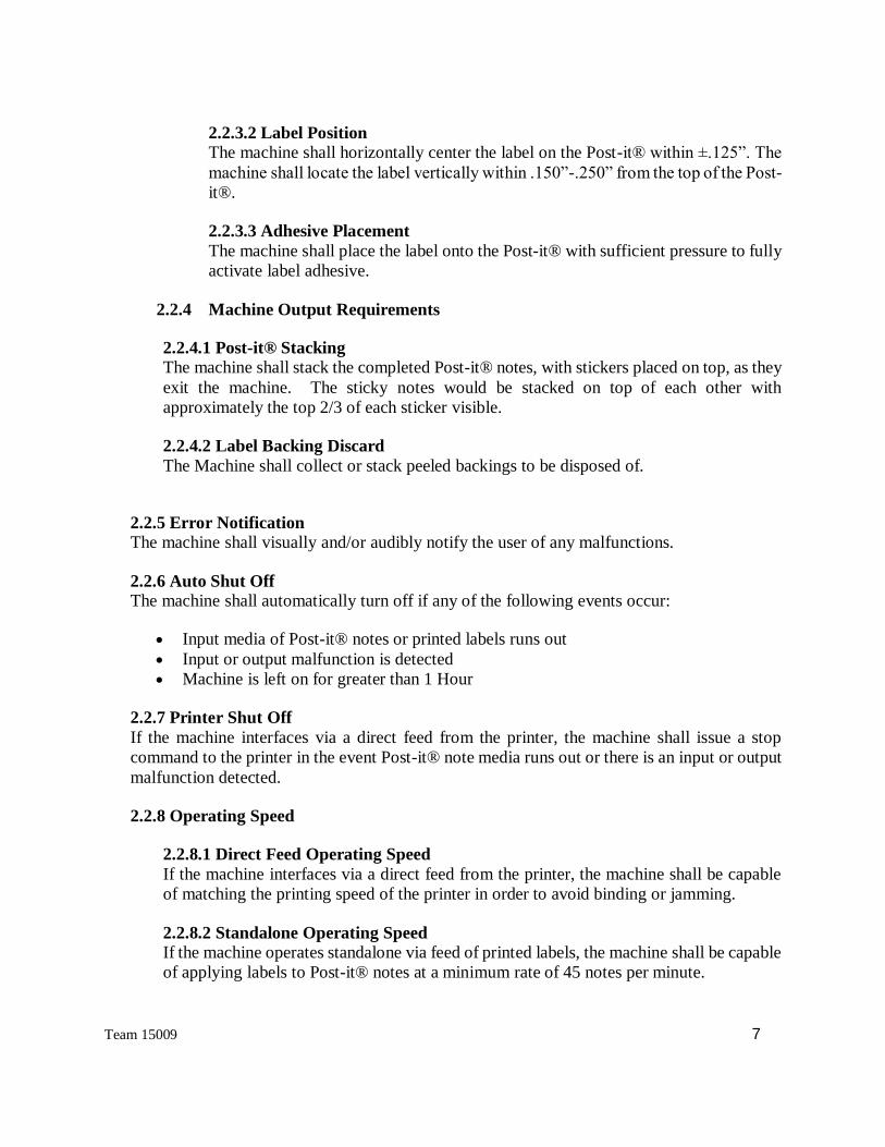
Figure 7 Figure 8
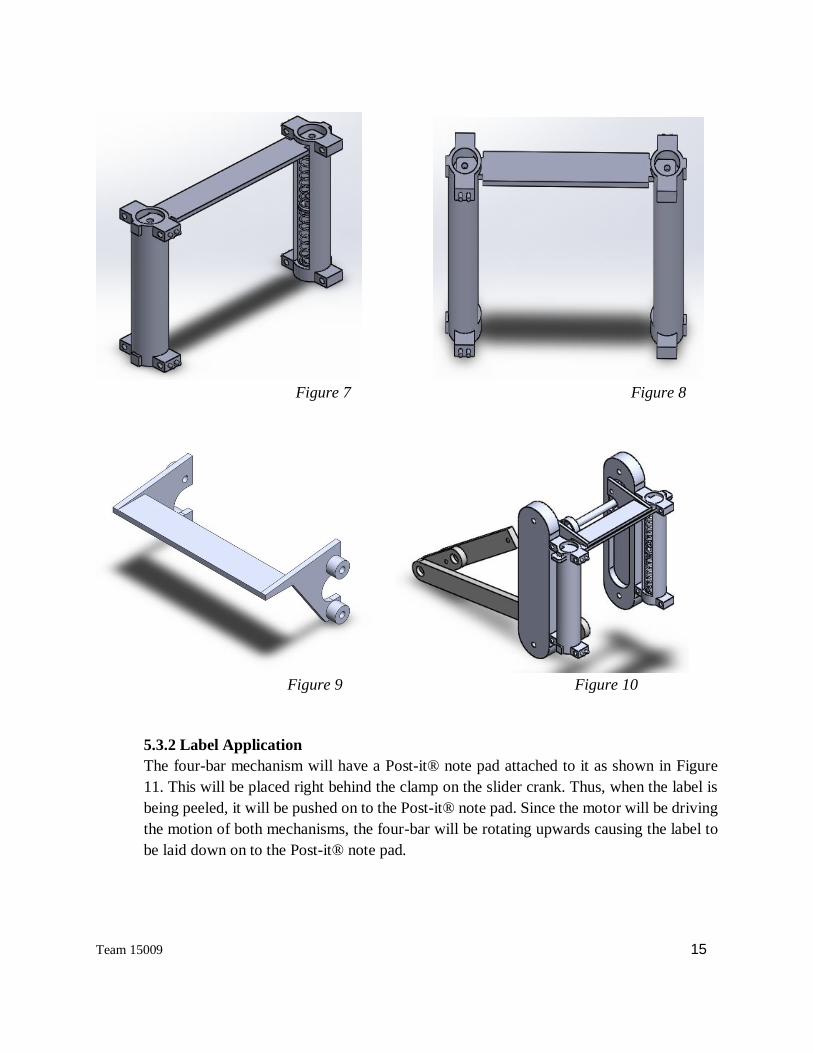
Figure 9 Figure 10
5.3.2 Label Application
The four-bar mechanism will have a Post-it® note pad attached to it as shown in Figure
11. This will be placed right behind the clamp on the slider crank. Thus, when the label is
being peeled, it will be pushed on to the Post-it® note pad. Since the motor will be driving
the motion of both mechanisms, the four-bar will be rotating upwards causing the label to
be laid down on to the Post-it® note pad.

Team 15009 16
Figure 11
5.4 PN (Post-it®-Note) Peeling and Stacking/Output Module
5.4.1 PN Housing Module
The Post-it® note housing module consists of three main components; the main housing,
back cover, and leveler. These components will be 3D printed and secured with screws, as
they do not undergo large amount of stress during operation. The main housing keeps the
Post-it® note in a fixed enclosed area while the leveler keeps the Post-it® notes at a certain
height in the housing. The backing is just a simple cover that has an elevated circular wall
that keeps the spring from moving from the center. The spring is a simple compression
spring that will be in contact with the back cover and leveler. It will continuously be in
compression while a stack of Post-it® is in the housing.
To keep the stack of Post-it® notes and leveler in place and not escape the housing while
in motion, the main housing component has clips at a specific place (⅓ from the bottom if
viewed from the top view) that will contain it. These clips are a main factor when the Post-
it® notes are to be peeled, location and functionality wise. This will be explained in the
Post-it® note peeling module section 5.4.2.
5.4.2 Post-it® Note Peeling/Output Module
The Post-it® note peeling module consists of two simple components. The first component
is a tray with an elevated wall that will prevent the peeled Post-it® notes from falling out
of place. The tray is wall-less at the top portion and has a thin plastic card that is elevated
by an angle. The second component is a rubber coated cam. The cam is coated in rubber
because it will cause more friction when in contact with Post-it® note.

Team 15009 17
How the Post-it® note will be peeled is that the rubber coated cam will be continuously
rotating and when the Post-it® note housing is in position with the cam, where the cam is
able to make contact with the Post-it® note, the cam will push one Post-it® note back. To
visualize this, imagine flipping a page of a book with one single finger. So the cam will do
this to the Post-it® note, trying to get it to flip over the clips mentioned in the Post-it® note
housing module.
Once a page of the Post-it® note is flipped over the clip, the mechanics of the system will
move the Post-it® note housing towards the thing plastic blade that will push through the
adhesive of the Post-it® note. This will be precisely between the two clips and be in
between the clip height. This will ensure that only a single Post-it® note is peeled.
5.5 Electrical Components
5.5.1 Microcontroller
The Arduino Zero will serve as our microcontroller. The Arduino will be responsible for
controlling the sensors, motors, motor shields, processing all the data gathered from the
sensors, LED output and checking for errors. The microcontroller will be able to determine
if the machine is out of Post-it® Notes, out of labels, and if a paper jam has occurred.
5.5.2 Motor Shield and Motor
To control the speed and motor position we considered two options. Option 1 was to build
a custom circuit and Option 2 was to purchase a commercial off the shelf (COTS)
component to control the motors. The Adafruit Motor Shield V2 was more compact and
offered more control over the motors and is fully compatible with the Arduino
microcontroller. Instead of using a latch and the Arduino's pulse width modulation (PWM)
pins, there is a fully-dedicated PWM driver chip onboard of the motor shield. This chip
handles all the motor and speed controls over I2C. Only two pins (SDA & SCL) are
required to drive the multiple motors. Figure 12 below is a schematic of how the Arduino
will interface with the motor shield. Figure 13 depicts how the motor shield will interface
with the motor.

Team 15009 18
Figure 12

Team 15009 19
Figure 13
Every movement in our system must be accurate and precise. The system requires the use
of stepper motors. A NEMA 17 200 steps/rev, 12v 350mA stepper motor will be
implemented in this design.
5.5.3 Label Detection
The IR Slot Sensor module for Arduino will be responsible for detecting labels at various
stages in the machine's cycle. The first slot sensor will be mounted at the input of the input
feeding module. Upon successful detection of a label, the Arduino will drive the motors
connected to the rollers within the input feeding module. The label will then be transferred
to the label peeling module. Another slot sensor will be mounted at the input of the label
peeling module. Once the label is detected at the input of the label peeling module the
Arduino will initiate a stop command.
6.0 Interface Document (Software)
The modules of the project communicate with the protocols and directions as described in Figure
14 below.

Team 15009 20
Figure 14
The Arduino with the help of the motor shield will control the speed and position of the motors.
These motors will only be driven when the optical sensors have successfully detected a label at the
input feeding module and at the label peeling module. The error module will consist of constantly
monitoring the feedback given by the optical sensors and the pulse width modulation (PWM)
output by the motors as shown in the figure above. A timer will be created such that if the optical
sensor at the input feeding module does not detect any labels within 10 seconds then it will notify
the user that the machine is out of labels. We will also command the Arduino to track the DC
motors reference angle so that if any deviations occur the Arduino would immediately stop the
movement of the motors and notify the user that there is a paper jam.
To begin implementing the code to control the motor with the motor shield we will start by
downloading the latest motor shield V2 Library and Accel Stepper Library. The code that is
required to control the motor with the motor shield is shown in Appendix 11.5.
7.0 Analysis
7.1 Analysis of Label Peeling and Application Module
In order to make the mechanism used in 5.3.1, the size of the links in the slider crank and
four-bar mechanism must be Grashof. What this means is that one of the links in the
mechanism will be able to rotate a full 360°.

Team 15009 21
In order for this to be true there is a general equation for each case. For the slider crank the
short crank arm must be shorter than the long arm attached to the slider, so S < L. This was
accomplished because the crank arm is S = 1.5in and the slider arm is L=3.0 in giving 1.5
in < 3 in. As for the four bar mechanism, the equation for this is S + L ≤ P + Q, where S
stands for short, L stands for long, and P and Q are the remaining two lengths. For this
mechanism, the short arm was S = 1.5 in, the long arm was L = 6.1 in, and the remaining
links were P = 1.8 in and Q = 6 in. This gives a relation of 1.5+6.1 in ≤ 1.8+6 in, simplifying
to 7.5 in ≤ 7.8 in. This shows that our mechanism is indeed Grashof and will work as
intended.
7.2 Analysis of Microcontroller
We needed a microcontroller in order to power the system, control and process data from
the motors and sensors, and to check for errors. We evaluated two of the more popular
microcontrollers the Arduino Zero and the Raspberry Pi B+. The data specifications are
listed in Table 2. The Raspberry Pi is more powerful than the Arduino Zero, but both have
their tradeoffs. The Raspberry Pi runs Linux operating software which requires software to
effectively interface with sensors and devices. This requires extensive programing to
effectively control any devices. Arduino directly executes simple code making it easier to
use. The Arduino can easily interpret and respond to a wide range of sensor data using the
code you put on it. The Arduino is also a sophisticated system that allows you to better
manage your devices. It is great for interfacing with other devices and actuators, where a
full operating system would be overkill for handling simple read and response actions. We
also tend to be more biased towards the Arduino Zero as there is more code available, more
access to libraries and we have experience working with the Arduino in many small
projects here at the University of Arizona.

Team 15009 22
Arduino
Zero
Raspberry
Pi B+
Price 54.95 39.95
Size 70.3 x 53.5 x
12.7mm
85 x 56 x
17mm
Clock Speed 48 MHz 900 MHz
Digital I/O
Pins
20 40
PWM Pins All but pins
2 and 7
27
Memory 256 KB 1 GB
Table 2
7.3 Analysis of Motors
For our design we needed motors to control the rollers and moving parts in our system. For
this type of application our system required the use of a stepper or servo motor. We
conducted trade studies and we found that stepper motors are simpler to
commission/maintain than servos, less expensive, don't lose steps or require encoders,
more stable at rest, and can hold their position. Also servo motors only have between four
to twelve poles in comparison to stepper motors which have roughly 50 to 100 poles. In
conclusion, stepper motors are much more accurate and precise and will be implemented
in our design.
8.0 Development Plan and Implementation
At the very start, a project plan was created with all milestones we hoped to complete. As far as
assembling the system, we did not meet the deadline set which was after Spring Break, instead it
was completed at the end of April. Our plan of three iterations could not take place due to the build
time. This was caused by a back up in the AME Machine Shop due to time and machines in use
by other teams. In addition to the backup of the AME Machine Shop, there were issues that were

Team 15009 23
found in our CDR design. Some of these issues included redesigning of the clamp because it was
too large in the initial design, rebuilding the label housing because it was also too large, and having
to redesign the slider crank guide rails to increase stability. As for the four bar mechanism, there
were minor errors made such as being too thick and not having a set screw to connect to the shafts.
The four bar mechanism was the main component in setting up the system causing the assembly
to be pushed back, which altered our project plan.
The assembly of the system took longer than we had expected. Even though the project plan
accounted for 2-3 extra weeks of buffer, the assembly time went into the buffer. Only one system
was built during this time. The model on Solidworks should have been made as complete as
possible, including mockups of components we didn’t have access to like the motors and Arduino.
We also did not take into account small items like screws, nuts, and washers. This would have
made the placement of components much easier during the assembly process.
Fortunately, a system was built during this time and has potential to be applied in the PSP process.
The original dimensions of the four bar mechanism and slider crank were successful once
implemented. The idea of the spring loaded housing for the labels works. The cam that is supposed
to lift one Post-it® has the potential operate successfully if it is remade with the right dimensions.
The Post-it® peeler also successfully shears off the single completed Post-it® note from the pad.
However, it still gets stuck to the edge of the peeler so it most likely needs a non-stick like material
placed on it. Our system shows that the design we created in the CDR has the potential to
successfully be implemented in PSP, but some modules must be refined first.

Team 15009 24
The following are images of the completed system.
Figure 15 Front view of the system
Figure 16 Back view of the system

Team 15009 25
Figure 17 Top view of the system
8.1 Milestones
● Systems Requirement Review (SRR)
● Preliminary Design Review (PDR)
● Critical Design Review (CDR)
● Mid-Semester Review (second semester)
● All Modules completed
● Testing Complete
● Completed Machine
● Final Design Review
● Design Day
Construction of the modules began in late January. The links to the four-bar and slider crank were
machined. The housings for the labels and Post-it® notes were also 3D printed at this time. While
they were created early, problems with their sizing were found. This caused delay since they had
to be redesigned and remade in the machine shop. The slider guide rails had to be redesigned in
Solidworks because it was discovered that they were under constrained. Testing on the motors had
already begun and those motors were operational.
By mid-semester review it was discovered that the original motors used were overheating. They
were underpowered for our application and had to be replaced with a different model. Re-
machining the links had been partially completed as well as reprinting the housings. The next thing
that had to be done was to machine the slider guide rails. That took about three weeks starting on
spring break due to back up in the AME machine shop. Once those went through, all modules had
been completed and assembly of the whole machine began in early April.

Team 15009 26
The casing materials were determined in early April and purchased. By Final Design Review we
had a plan laid out for the assembly of the machine. However, once all the modules were starting
to be assembled together, spacing issues were discovered in the mechanical portions of the
machine. Thus, they had to be adjusted in the machine shop causing more delays in assembly.
After completing all modifications, the machine was finally assembled near the end of April.
Unfortunately, the clamping mechanism was broken in this period, and due to the shortage of time
we had to proceed without it. The electronics module was then implemented into the machine in
the days leading up to Design Day.
9.0 Requirements Review / Acceptance Test Plan / Performance
Requirements Test Plan High-3 Medium-2 Low-1
Requirement
Met (Yes/No) Comments
2.1.1 Machine Size
Measure all the
components and dynamics
of the components and
make sure that they will fit
in our required dimensions
Fits in 1510 Pelican
case along with
Brother QL printer
with 2'' of padding
on edges.
Fits in 1620
Pelican case
along with
Brother QL
printer with 2''
of padding on
edge.
Does not fit
in either
Pelican
cases.
2
The 1620
Pelican case fits
the PSP
machine,
printer, any
cables needed,
Post-It Notes,
and extra labels.
2.1.2.1 Sharp Edges
During CAD, will fillet all
the sharp edges on the
exterior housing, with
drawings to show proof
No sharp edges
exposed in system
Minor amounts
of sharp edges N/A 2
There are minor
edges due to the
bolts sticking
out.
2.1.2.2 Cutting Edges N/A N/A N/A N/A N/A
2.1.2.3
Dangerous or
Harmful
Materials
Verify that the components of
the machine will pass TSA
regulations
TSA Approved. N/A
Does not
meet
regulations
3
The Pelican
case will be too
large to be used
as carry on so it
will be checked
in, meeting all
of TSA
requirements.
2.1.2.4 Electrical
Hazards
Inspection of all wires and
electrical components to
ensure all wires are properly
connected, insulated, and
grounded.
Wired are connected,
insulated, and
grounded.
N/A Wires
exposed. 3

Team 15009 27
2.1.2.5 Travel
Requirements
Verify that the components of
the machine will pass TSA
regulations. Ensure that all
components are not on the
prohibited items list on the
TSA regulations
TSA Approved. N/A
Does not
meet
regulations
3
The Pelican
case will be too
large to be used
as carry on so it
will be checked
in, meeting all
of TSA
requirements.
2.2.1.1 Post-it® Sizes
Measure the Post-it® note
housing to determine whether
the Post-it® note sizes will fit
and run with the machine
Post-it® Note
housing is within 3
+/- .125''.
N/A
The Post-it®
note housing
does not
match the
required
specifications
.
3
The Post-It
Note housing
was made with
extra room for
clearance.
2.2.1.2 Post-it® Pad
Sizes
Determine if the machine will
function correctly with the
three different Post-it® sizes
The machine
functions with all 3
sizes.
The machine
functions will
only 3x3 size.
N/A 2
The housing
only fits 3x3
size.
2.2.1.3 Multiple Color
Post-it® Pads
Test the amount of time it
takes to quickly change and
replace Post-it® notes pads
The time to change
the pad is less than
15 seconds.
The time to
change the pad
is in between 15
and 30 seconds.
The time to
change the
pad is more
than 30
seconds.
3
The Post-It
slides into the
housing making
it quick to
change.
2.2.2.1 Printer
Compatibility N/A N/A N/A N/A N/A
The system is
not a direct
feed.
2.2.2.2 Label Media
Compatibility
Have the machine operate
under normal conditions and
measure the temperature of
the components that might
alter the appearance of the
thermal sensitive label
No alteration done
due to heat from the
machine to the label
media
N/A N/A 3
There is no
change to the
label media.
2.2.2.3 Label Media
Sizes
Run 2 separate tests to verify
that the machine input shall
be capable of accepting 1.2"
and 2.5" printed media.
The machine input
accepts both 1.2'' and
2.5'' printed media.
The machine
input accepts
2.5'' printed
media.
N/A 2
The system
does not
accommodate
for the smaller
size labels.
2.2.2.4 Label Media
Form
Insert stack of printed labels
into input tray to ensure
machine is capable of
accepting label media in
either strip of multiple labels
or as a stack of pre-cut labels.
The system input is
capable of accepting
strip of labels and/or
stacks of pre-cut
labels.
The system
input is capable
of accepting
stacks of pre-cut
labels.
N/A 2
There is not a
cutting
mechanism in
the system.

Team 15009 28
2.2.3.1 Label
Orientation
Visually inspect assembled
labels to ensure the adhesive
is located on the top of the
back side when viewing text
The orientation of
the label and Post-
it® is right side up
N/A N/A N/A
The system is
currently unable
to peel the
label.
2.2.3.2 Label Position
Insert the label into the
machine where the label
orientation will be right side
up and the adhesive of the
Post-it® note will be on the
top of the back side
The label is centered
horizontally within
+/- 0.125'' and
vertically within +/-
0.25''.
The label is
hanging off of
the Post-it®
Note.
The label is
not on the
Post-it®
Note.
1
The system is
currently unable
to peel the
label.
2.2.3.3 Adhesive
Placement
Run the system and inspect
how secure the labels are on
the Post-it® Notes. The label is secure
on the Post-it® Note,
all corners are flat.
The label is
secure on the
Post-it® Note,
at least 2
corners are flat.
The label is
not
completely
attached to
the Post-it®
Note.
1
The system is
currently unable
to peel the
label.
2.2.4.1 Post-it®
Stacking
Operate the machine
normally and inspect if the
completed Post-it® notes are
outputted in an orderly
fashion
The Post-it® Notes
are stacked in a 2/3
sequence.
The Post-it®
Notes are
stacked on top
of each other.
The Post-it®
Notes are
separated
from one
another.
N/A
The system is
currently unable
to peel the
label.
2.2.4.2 Label Backing
Discard
Visually inspect that the label
backing is discarded and not
obstructing the flow of the
machine.
The discarded label
backing does not
obstruct the flow of
the machine.
N/A
The
discarded
label backing
does obstruct
the flow of
the machine.
N/A
The system is
currently unable
to peel the
label.
2.2.5 Error
Notification
Simulate and/or produce error
conditions in order to test
system to ensure all error are
recognized by the system and
the system outputs the correct
notification.
The machine
visually and audibly
notify the user.
The machine
visually and/or
audibly notify
the user.
The machine
does not
notify user.
1
The error
notification
module was not
implemented
into the
machine.
2.2.6 Auto Shut Off
Operate the machine in three
different set of conditions
that is supposed to trigger and
auto shut off:
1) Input media of Post-it®
notes or printed labels runs
out
2) Input or output
malfunction is detected
3) Machine is left on for
greater than 1 Hour
The machine auto
shut off when any of
the 3 conditions
occur.
The machine
auto shut off
when at least
one of the
conditions
occur.
The machine
does not auto
shut off.
1
The auto shut
off was not
implemented
into the
machine.

Team 15009 29
2.2.7 Printer Shut Off N/A N/A N/A N/A N/A
2.2.8.1 *Direct Feed
Operating Speed N/A N/A N/A N/A N/A
2.2.8.2 *Standalone
Operating Speed
Have the machine operate
under normal conditions and
time the output amount of
Post-it® notes with label
applied in intervals of 1
minute.
Machine outputs
completed Post-it®
notes at a rate of 45
notes per min or
higher.
Machine outputs
completed Post-
it® notes at a
rate of in
between 20 and
45 notes per
min.
Machine
outputs
completed
Post-it®
notes at a rate
of 20 notes
per min or
lower.
N/A
The system is
currently unable
to peel the
label.
2.2.9 Operating Noise
Measure printer and machine
dB levels using decibel
meter.
The decibel of the
system is < +/- ##
from the printer's dB
N/A
The decibel
of the system
is > +/- ##
from the
printer's dB
1
The noise
comes from the
multiple motors
used in the
system. The
system is
roughly 70 dB
with an average
of 30 dB. A
“Sound Meter”
app was used.
2.2.10.
1
Physical On/Off
Switch
Visually inspect that the
machine design will have a
physical on/off switch There is a physical
on/off switch N/A N/A 3
There is a
physical on and
off switch
connecting to
the Arduino
microcontroller
2.2.10.
2
Power
Requirements
Test the system using a
voltage converter to ensure
the system functions properly
when supplied by 110-120V
or 220V power.
The system functions
on 110-120 and
220V power.
The system
functions on
110-120V
power.
N/A 3
The system runs
on 110-120V
power.
2.3.1 Setup/Teardown
Time
Test the amount of time it
takes to set up machine when
fully assembled and
disassembled to ensure it
takes no longer than 2
minutes to complete this task
The average time to
assemble and
disassembled is less
than 2 minutes
The average
time to assemble
and disassemble
is between 2 to
5 minutes.
The average
time to
assemble and
disassemble
is over 5
minutes.
3
The only
assembling
needed is to
screw on the
lid.
2.3.2 Additional
Tooling
While assembling the
machine normally, document
what tools were used. If
many tools were used,
redesign the machine to use
Amount of
additional tools is 1
or lower
Amount of
additional tools
is in between 1
and 5
Amount of
tools
required is 5
or more
1
Everyday use,
required tooling
comes out to 3.
To build the
system. The

Team 15009 30
the same tool to keep tooling
to a minimum
first time,
tooling comes
out to 8.
2.3.3 Ease of Use
Provide instructions to
multiple users on how to set-
up, teardown, operate the
system. Have users provide
feedback on the ease of use.
User does not need
guidance in set-up,
teardown and
operate system.
User needs
minor guidance
in set-up,
teardown, and
operate system.
User has no
idea how to
set-up,
teardown and
operate
system.
N/A
The system is
currently unable
to peel the
label.
2.4.1 Maintenance
Frequency
Input labels in batches of 100
into system until 5,000 label
have been assembled and
ensure that no maintenance is
required other than general
cleaning.
5000 labels
assembled w/ no
maintenance
2500 labels
assembled w/ no
maintenance
1250 labels
assembled w/
no
maintenance
N/A
The system is
currently unable
to peel the
label.
2.4.2 System Lifetime
Determine the amount of
stress the system will
regularly undergo and
compare these results with
the components of the
machine and determine if the
components meet the system
lifetime requirement of three
years
System will last a
minimum of 3 years
System will last
1 to 3 years
System last
less than 1
year
N/A
The system is
currently unable
to peel the
label.
2.4.3 Replaceable
Parts
Determine which components
will need to be replaced and
from the Bill of Materials,
determine if those
components are
commercially available
All replaceable parts
are commercially
available
Some
replaceable
parts are custom
made.
All
replaceable
parts are
custom
made.
2
Some of the
components are
3D printed
while the links
are custom
made.
For 2.1.1, it can be seen in Figure # that all of the required components fit inside of the Pelican
1620 case. From the sponsor, “to be functional, a kit must be able to carry the fo llowing: the PSP
Sticker machine, a printer, two stacks of Post it notes each 3x3x8 inches, two rolls of paper for the
printer (about 3x3x6 inches) and Power and data cords for the printer and sticker machine.”

Team 15009 31
Figure 18
For 2.2.9, the noise level was testing using an app called “Sound Meter”. The results are shown in
Figure # and Figure #. The first figure is from the Brother QL-1050 Printer and the other is from
the PSP Machine.
Figure 19
Most of the required testing could only be done if the system was successful in peeling and
applying the label. Unfortunately, the system was not able to complete the task. This was due to
not taking in consideration of the torque needed to move the four bar mechanism. When the system

Team 15009 32
was being tested using the motors, there was simply not enough to pull the mechanism back to its
starting position. If we had enough time, a bigger gear could have been purchased to increase the
1:1 ratio to 1:3. The lesson learned from this is to treat the design phase as the final design and
learn about how mechanisms work before designing to have a better understanding of what needs
to be included.
Another factor of the system not peeling is not taking in consideration where the motors were
going to go inside of the system. We assumed that it would fit in the extra spaces until the system
was built. Thus the spacing between the two slider crank mechanism had to be enlarged and instead
of one motor being used for the peeling mechanism, two had to be used. This is an error that could
have been caught in Solidworks if we had a placeholder for the motors and realized that one of the
rods had to go around 360 degrees. It was originally planned to have only one motor driving both
the four bar mechanism and the slider crank. However, once the system was being assembled it
was discovered that the rotating connecting rods to both mechanisms would crash into the shaft.
This made it necessary to add another motor to the system.
Based on feedback from the customer on Design Day, they were disappointed that the machine
was not able to meet all of the requirements. However, they expressed interest in what was built
of the machine and the concepts that it was able to display, since the machine displayed most of
what was outlined in the CDR. They wanted all of the schematics, models, and drawings of our
system to attempt to improve on it next year with another senior design team.
10.0 Closure
While many minor details changed throughout the semester for our project, most of the core
theoretical aspects of our design were completed successfully. The concept for both the label and
Post-it® spring loaded housings kept each media in place as intended after some size
modifications. The analysis done on the slider crank and four-bar mechanism panned out as
intended. While they were not able to be powered by the motor, the motion that they displayed
when manipulated by hand followed exactly what was laid out in the analysis. The concept for the
Post-it® peeler worked when tested manually. The edge was able to successfully peel the Post-it®
from the pad. However, the edge would need to be coated with some form of non-stick material
because the Post-it® notes stick to it. Another success was the wiring of the Arduino
microcontroller and coding that was involved in it. The Arduino showed how simple it can be to
automate the process and that this machine can be almost plug and play with minimal setup. While
there were many successes with this project, there is still much room for improvement.
After completing our design, we found that with additional resources and time, the machine can
be improved. There are components that need to be redesigned and parts that need to be changed,

Team 15009 33
like the size of the gears. Accurate calculations should have been done before purchasing the gears.
A new peeling mechanism could have been redesigned and 3D printed to accommodate the
enlargement of the slider crank spacing. The exterior of the system could have been built and
supported better with time. It could have been modeled in Solidworks to see where all the
components should have been placed and more aesthetically pleasing if we remade our prototype.
Money was not an issue for the system since there is still a little under $2000 leftover in the budget.
That leftover amount was supposed to go into building a second system, but the original did not
work. Because the original machine did not work, we had to scale back on some tests that were
originally planned. This includes tests that compare the system to manually peeling the labels and
tests for the performance aspects of the machine. For example, test 2.2.8.2 Standalone Operating
Speed could not be completed because the machine cannot peel labels. This causes problems in
other tests like 2.4.2 System Lifetime since it would not make sense to test the system lifetime of
a machine that is not performing its main task.
Most of the problems within our system stemmed from the fact that we did not fully model the
system before assembly. All of the theoretical models were accounted for, such as with the linkages
and the housings, but all of the connections, placements, and enclosing were ignored. The modules
were created separately and not fully assembled in Solidworks before building it in real life. If we
had taken these things into account, we would have found all of the problems that we encountered
before building anything, which would have saved time and money on the project. The main lesson
to learn from our project is the importance of modeling the final design first opposed to parts of it
so that potential problems can be identified early and the design can be changed accordingly before
parts are ordered and the machine is assembled.
10.1 Next Steps
If Raytheon chooses to continue this project for next year’s senior design group and uses this
concept, we would recommend the following adjustments.
First, the clamping mechanism should be redesigned. While we were not able to test it due to sizing
errors in our system, we suspect that this clamping concept will not be precise enough to clamp on
to the few millimeters of backing that is available on the label. In addition to that, the spacing on
the slider crank must be placed very precisely, or else the slider will not move smoothly as shown
in our project.
Second, both housings would need some minor changes with the spring loading. The spring
currently presses up with too much force on the label housing, causing multiple labels to be pressed

Team 15009 34
through in the input feeding module. Perhaps a wall in front of the tray will block the rest of the
labels from passing through. As for the Post-it® housing, the force that it presses up with makes
it difficult for the cam to lift up a single Post-it®.
Third, the size of the cam is currently too short. So sizing of it would have to be enlarged because
the shaft currently contacts with the Post-it® housing since it is so short.
Fourth, the Post-it® peeling mechanism would require some form of non-stick coating on it to
prevent the Post-it® from sticking to the edge. It could also have something that dislodges the
Post-it® rather than using a non-stick coating.
Fifth, the sizing of the gears on the motor must be corrected. A bigger gear on the motor will allow
for more power to be transmitted to the slider crank and four-bar mechanism, making the
movement of those mechanisms much smoother. Something that can be considered with those two
mechanisms is that the measurements made from the analysis can be scaled down. This would
allow for a smaller system that could potentially fit into the smaller 1510 case.
Most of these adjustments should be made in the provided Solidworks model. As stated in the
closure, it is important to model all of the sizing of the machine before building. Almost all of
these problems can be solved by creating a fully comprehensive model in Solidworks first.
11.0 Appendices
11.1 System Requirements
Number Type Description Priority
1
1.1 Physical The system shall closely match the size of a
Brother QL-1050 printer
Must
1.2 Physical The system shall not have any exposed sharp
edges, harmful or dangerous materials or
Must

Team 15009 35
electrical components that could pose as a safety
hazard to users
1.3 Physical The system shall not be in violation with any
TSA regulations
Must
1.4 Physical The system shall be safe to carry on board a US
passenger aircraft
Must
2
2.1 Functional The system shall accommodate various Post-it®
size configurations
Must
2.2 Functional The system shall be capable of accepting up to a
minimum of 100 count Post-it® pad, and
multiple color Post-it® pads
Must
2.3 Functional The system shall not generate sufficient heat to
discolor/fade or otherwise damage the thermal
paper
Must
2.4 Functional The system shall accept printed media 1.2” or
2.5” (on a roll)
Must
2.5 Functional The label should be placed a Post-it® note such
that adhesive is located on the top of the
backside when viewing text
Desired
2.6 Functional The system shall horizontally and vertically
center the label on the Post-it®
Must
2.7 Functional The system shall stack the completed Post-it®
notes
Must
2.8 Functional The system shall collect and discard the label
backing
Must
2.9 Functional The system shall visually and/or audibly notify
the user of any malfunctions
Must

Team 15009 36
2.10 Functional The system should be set-up/torn down in less
than two minutes (each)
Desired
2.11 Functional The system shall be supplied with any
additional tooling
Must
2.12 Functional The system should be easy to use Must
3
3.1 Electrical The system shall include a physical on/off
switch
Must
3.2 Electrical The system shall be compatible to international
power standards
Must
4
4.1 Reliability and
Supportability
The system shall assemble a minimum of 5000
labeled Post-it® notes with no maintenance
Must
4.2 Reliability and
Supportability
The system shall remain functional for a
minimum of three years
Must
4.3 Reliability and
Supportability
The system shall have replaceable parts Must
5
5.1 Constraints The system shall be compatible with the Brother
QL-1050 printer
Must
5.2 Constraints The system should not exceed the amount of
$3,500
Desired
5.3 Constraints The system shall be completed by May 3rd, 2016 Must
6
6.1 Trade-off The machine shall be capable of applying labels
to Post-it® notes at a minimum rate of 45 notes
per minute when it has a stand-alone feed
Must

Team 15009 37
11.2 SolidWorks Drawings
11.2.1 Input Feeding Module
11.2.1.1 shows the dimensions of the Resize Input Frame of the Input Feeding Module.

Team 15009 38
11.2.1.2 shows the the dimensions of ResizeInput Frame 2-3 of the Input Feeding Module.

Team 15009 39
11.2.1.3 shows the dimensions of slot sensor rail (Resize Input Frame 4-5) of the Input Feeding
Module.

Team 15009 40
11.2.1.4 shows the dimension of the other side rail (Resize Input short length) for the Input
Feeding Module.

Team 15009 41
11.2.1.5 shows the dimension of the Input Plate for the Input Feeding Module.

Team 15009 42
13.2.1.6 shows the Input Feeding Module without the rollers.
Team 15009 43
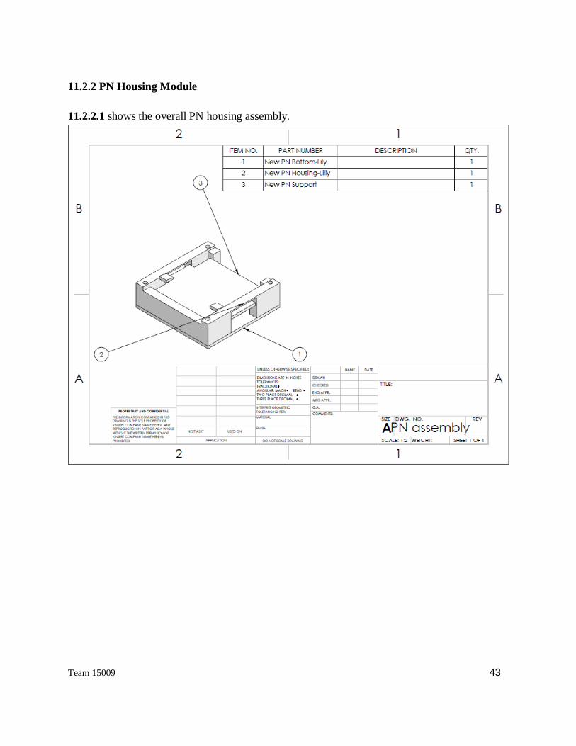
11.2.2 PN Housing Module
11.2.2.1 shows the overall PN housing assembly.

Team 15009 44
11.2.2.2 shows the dimensions of the main frame of the housing. 3D-Printed.
Team 15009 45
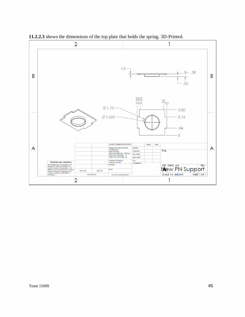
11.2.2.3 shows the dimensions of the top plate that holds the spring. 3D-Printed.

Team 15009 46
11.2.2.4 shows the dimensions of the bottom plate that holds the spring. 3D-Printed.

Team 15009 47
11.2.3 PN Peeler Module
11.2.3.1 shows the assembly of the PN Peeler. 3D-Printed. The knife edge is a plastic card.

Team 15009 48
11.2.3.2 shows the dimensions of the PN Peeler Base. (Scooper)

Team 15009 49
11.2.3.3 shows the dimensions of the cam used to lift one PN from the PN pad.

Team 15009 50
11.2.4 Label Peeling and Application Module Mechanism
11.2.4.1 shows the dimensions of “clampbearing” component of the spring clamp assembly

Team 15009 51
11.2.4.2 shows the dimensions of the “midholder” component of the spring clamp assembly

Team 15009 52
11.2.4.3 shows the dimensions of the “clampslot” component of the spring clamp assembly.

Team 15009 53
11.2.4.4 shows the dimensions of the “clamp” component of the spring clamp assembly

Team 15009 54
11.2.4.5 shows the spring assembly along with all the component annotations

Team 15009 55
11.2.4.6 shows the dimensions of the crank used on the four bar mechanism and slider crank.
11.2.4.7 shows the dimensions of the link used on the four bar mechanism.
Team 15009 56
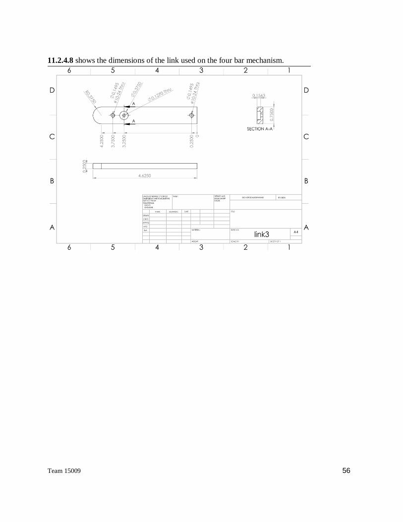
11.2.4.8 shows the dimensions of the link used on the four bar mechanism.

Team 15009 57
11.2.4.9 shows the dimensions of the link used on the four bar mechanism.
11.2.4.10 shows the dimensions of the connecting rod used on the slider crank.

Team 15009 58
11.2.4.11 shows the dimensions of the slots used on the slider crank.

Team 15009 59
11.2.4.12 shows the dimensions of the sliderss used on the slider crank.
11.2.4.13 shows the assembly drawing of the four bar mechanism.

Team 15009 60
11.2.4.14 shows the assembly drawing of the slider crank

Team 15009 61
11.2.4.15 shows the drawing of connection between the link in 13.2.4.5 and the PN Peeling
Housing.
11.3 Project Management
11.3.1 Gantt Chart

Team 15009 62

Team 15009 63
11.3.2 Risk Analysis
11.3.2.1 Risk Register
# Type Description P I RF
1 T1 Labels do not peel completely when the machine is run .20 .80 .16
2 T2 The Post-it® notes are not peeled from the pad correctly .15 .7 .105
3 T3 A paper jam is not detected by the machine .15 .15 .023
4 T4 There is an interfacing problem with the machine working
with the Brother Printer label type
.01 1 .01
5 T5 Electrical components powering the machine short out .1 .8 .08
6 T6 The Post-it® notes are not stacked when output from the
machine
.25 .5 .125
7 PM1 Task times and dependencies are incorrectly identified
causing schedule slips to occur
.15 .6 .09
8 PM2 Inaccurate cost estimation for parts and resource utilization
cause the project to go over budget
.05 .5 .025
9 O1 Test equipment or test environment is not available when
needed
.15 .6 .09

Team 15009 64
10 O2 Project members do not finish their assigned tasks on
schedule
.10 .4 .04
11 E1 Parts do not arrive on time .10 .4 .04
11.3.2.2 Risk Severity Matrix
11.3.2.3 Mitigation Plan
Risk Event Response Contingency Plan Trigger Responsible
Peeling Labels &
Post-it® note
problems
Mitigate: Test
Prototype
Look into alternative
parts to perform
function
Not solved within
3 days
Mechanical Team
Interface Problems Mitigate: Test
Prototype
Modify design with
different components
for compatibility
Not solved within
2 days
Software/Electrical
Team
Error Detection Mitigate:
Prototype
demonstration
Look into alternative
suppliers that produce
similar parts
Do not receive
parts on schedule
Software Team
Vendor Problems Mitigate: Contact vendor to Do not receive Purchasing Lead

Team 15009 65
select a
reliable vendor
resolve issue and also
look into alternative
suppliers that produce
similar parts
parts on schedule
Project
Management
Issues
Mitigate: Get
help from
peers and
sponsor
Work around until
help comes
Project does not
look like it will be
finished on time or
meet budget
Project Management
Team
Project Team
Issues
Mitigate:
Improve
communicatio
n and work
balance
Create a more detailed
schedule and WBS
and make sure team
members understands
their tasks
Not meeting
deadlines or
contact from
sponsors
Team Leader
Testing Equipment
Availability
Mitigate:
Coordinate
availability
with facility
manager
Work around until get
in contact with facility
manager
Receive
notification that
testing equipment
will not be
available at the
time the team
needs it
Team Leader

Team 15009 66
11.4 Budget and Suppliers

Team 15009 67
*Yellow highlighted box means that the taxes and shipping have not been accounted for. The
“Bolts/Nuts” term was for miscellaneous screws, nuts, washers, and bolts we were missing or
needing during the assembly process of the system.

Team 15009 68
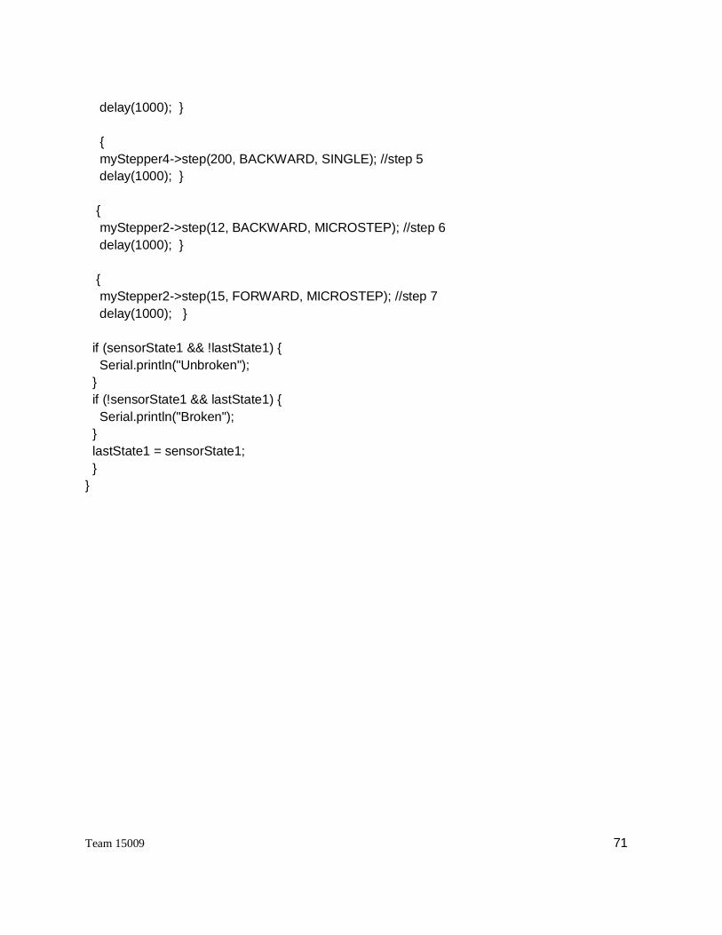
11.5 Code for Motor Control
Include the required libraries
Make sure you #include the required libraries
#include <Wire.h>
#include <Adafruit_MotorShield.h>
#include "utility/Adafruit_PWMServoDriver.h"
Create the Adafruit_MotorShield object
Adafruit_MotorShield AFMS = Adafruit_MotorShield();
Create the stepper motor object
Request the Stepper motor from the Adafruit_MotorShield:
Adafruit_StepperMotor *myMotor = AFMS.getStepper(200, 2);
with getStepper(steps, stepper#). Steps indicates how many steps per revolution the motor has. A
7.5degree/step motor has 360/7.5 = 48 steps. Stepper# is which port it is connected to. If you're
using M1 and M2, its port 1. If you're using M3 and M4 indicate port 2
Set default speed
Set the speed of the motor using setSpeed(rpm) where rpm is how many revolutions per minute
you want the stepper to turn.
Run the motor
Then every time you want the motor to move, call the step(#steps, direction, steptype)procedure.
#steps is how many steps you'd like it to take. direction is either FORWARD or BACKWARD
and the step type is SINGLE, DOUBLE, INTERLEAVE or MICROSTEP.
● "Single" means single-coil activation
● "Double" means 2 coils are activated at once (for higher torque)
● "Interleave" means that it alternates between single and double to get twice the resolution
(but of course its half the speed).
● "Microstepping" is a method where the coils are PWM'd to create smooth motion between
steps.
Code for microcontroller
/*
This is a test sketch for the Adafruit assembled Motor Shield for Arduino v2
It won't work with v1.x motor shields! Only for the v2's with built in PWM
control

Team 15009 69
For use with the Adafruit Motor Shield v2
----> http://www.adafruit.com/products/1438
*/
#include <Wire.h>
#include <Adafruit_MotorShield.h>
#include "utility/Adafruit_MS_PWMServoDriver.h"
Adafruit_MotorShield AFMStop(0x61); // top motorshield addressed 61
Adafruit_MotorShield AFMSbot(0x60); // bottom motorshield, default address 60
// On the bottom shield, connect two steppers to port M1/M2, each with 200 steps
Adafruit_StepperMotor *myStepper4 = AFMSbot.getStepper(200, 1);
Adafruit_StepperMotor *myStepper2 = AFMSbot.getStepper(200, 2);
// On the top shield, connect two steppers to port M3/M4, each with 200 steps
Adafruit_StepperMotor *myStepper1 = AFMStop.getStepper(200, 1);
Adafruit_StepperMotor *myStepper3 = AFMStop.getStepper(200, 2);
//initialize led at pin 13
int led1 = 13;
//initialize slot sensor at pin 2
int irsensor1 = 2;
//initialize states of ir sensor
int sensorState1 = 0, lastState1=0;
void setup() {
// initialize the LED pin as an output:
pinMode(led1, OUTPUT);
// initialize the sensor pin as an input:
pinMode(irsensor1, INPUT);
digitalWrite(irsensor1, HIGH); // turn on the pullup
AFMSbot.begin(); // Start the bottom shield
AFMStop.begin(); // Start the top shield

Team 15009 70
myStepper2->setSpeed(2); // set speed of stepper motors
}
int i;
void loop() {
// read the state of the pushbutton value:
sensorState1 = digitalRead(irsensor1);
// check if the sensor beam is broken
// if it is, the sensorState is LOW:
if (sensorState1 == LOW) { //& sensorState2 == LOW
// turn LED on:
digitalWrite(led1, HIGH);
}
else { ////(sensorState1 == HIGH & sensorState2 == LOW)
// turn LED off:
digitalWrite(led1, LOW);
{
myStepper1->step(200, FORWARD, SINGLE); //step 1, (# of steps, direction, type of steps)
delay(1000); }
{
myStepper2->step(11, FORWARD, MICROSTEP); //step 2
delay(1000); }
{
myStepper3->step(50, BACKWARD, MICROSTEP); //step 3
delay(1000); }
//{
// myStepper3->step(200, FORWARD, DOUBLE); //step 3.5
//delay(1000); }
{
myStepper2->step(12, BACKWARD, MICROSTEP); //step 4
Team 15009 71
delay(1000); }
{
myStepper4->step(200, BACKWARD, SINGLE); //step 5
delay(1000); }
{
myStepper2->step(12, BACKWARD, MICROSTEP); //step 6
delay(1000); }
{
myStepper2->step(15, FORWARD, MICROSTEP); //step 7
delay(1000); }
if (sensorState1 && !lastState1) {
Serial.println("Unbroken");
}
if (!sensorState1 && lastState1) {
Serial.println("Broken");
}
lastState1 = sensorState1;
}
}