Embed Size (px)
Citation preview

HWAT-ECO
INSTALLATION AND OPERATION MANUAL FOR HOT WATER TEMPERATURE MAINTENANCE SYSTEM ELECTRONIC CONTROLLER
THERMAL MANAGEMENT SOLUTIONS WWW.THERMAL.PENTAIR.COM
ii EN-RaychemHWATECOcontroller-IM-H57340 03/13
Important Safeguards and Warnings
WARNING: FIRE AND SHOCK HAZARD
Raychem HWAT Systems must be installed correctly to ensure proper operation and to prevent shock and fire. Read these important warn-ings and carefully follow all the installation instructions.
• To minimize the danger of fire from sustained electrical arcing if the heating cable is damaged or improperly installed, and to comply with Pentair Thermal Management requirements, agency certifica-tions, and national electrical codes, ground-fault equipment protec-tion must be used on each heating cable branch circuit. Arcing may not be stopped by conventional circuit breakers.
• Approvals and performance are based on the use of Pentair Thermal Management parts only. Do not substitute parts or use vinyl electrical tape.
• Bus wires will short if they contact each other. Keep bus wires separated.
• Connection kits and heating cable ends must be kept dry before and during installation.
• The black heating cable core is conductive and can short. They must be properly insulated and kept dry.
• Damaged bus wires can overheat or short. Do not break bus wire strands when preparing the cable for connection.
• Damaged heating cable can cause electrical arcing or fire. Do not use metal attachments such as pipe straps or tie wire. Use only Pentair Thermal Management approved tapes and cable ties to secure the cable to the pipe.
• Do not attempt to repair or energize damaged cable. Remove damaged cable at once and replace with a new length using the Raychem RayClic-S splice kit. Replace damaged connection kits.
• Use only fire-resistant insulation which is compatible with the application and the maximum exposure temperature of the system to be traced.
iiiEN-RaychemHWATECOcontroller-IM-H57340 03/13
Table of Contents
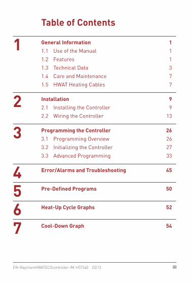
1 General Information 11.1 Use of the Manual 11.2 Features 11.3 Technical Data 31.4 Care and Maintenance 71.5 HWAT Heating Cables 7
2 Installation 92.1 Installing the Controller 92.2 Wiring the Controller 13
3 Programming the Controller 263.1 Programming Overview 263.2 Initializing the Controller 273.3 Advanced Programming 33
4 Error/Alarms and Troubleshooting 45
5 Pre-Defined Programs 50
6 Heat-Up Cycle Graphs 52
7 Cool-Down Graph 54
iv EN-RaychemHWATECOcontroller-IM-H57340 03/13
A
F
B
C
D
E
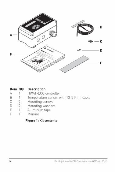
Item Qty DescriptionA 1 HWAT-ECO controllerB 1 Temperature sensor with 13 ft (4 m) cableC 2 Mounting screwsD 2 Mounting washersE 1 Aluminum tapeF 1 Manual
HWAT-ECO
INSTALLATION AND OPERATION MANUAL FOR
HOT WATER TEMPERATURE MAINTENANCE SYSTEM
ELECTRONIC CONTROLLER
THERMAL MANAGEMENT SOLUTIONS
WWW.THERMAL.PENTAIR.COM
Figure 1: Kit contents
vEN-RaychemHWATECOcontroller-IM-H57340 03/13
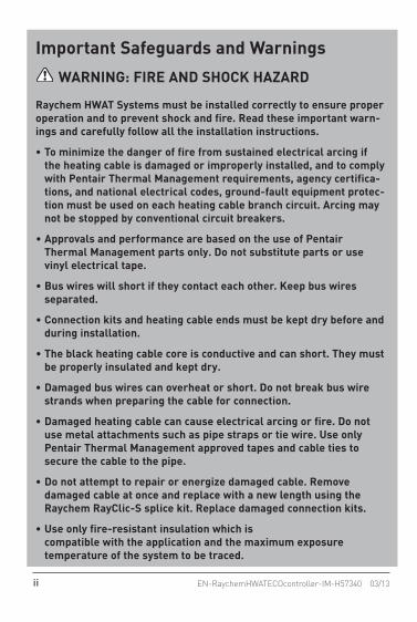
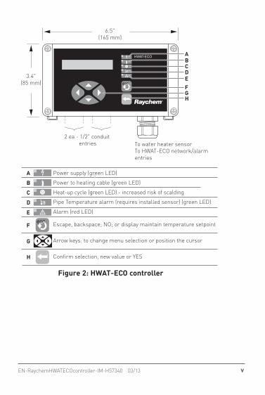
Power supply (green LED)
Power to heating cable (green LED)
Heat-up cycle (green LED) - increased risk of scalding
Pipe Temperature alarm (requires installed sensor) (green LED)
Alarm (red LED)
Escape, backspace; NO; or display maintain temperature setpoint
Arrow keys: to change menu selection or position the cursor
Confirm selection, new value or YES
6.5"(165 mm)
2 ea - 1/2" conduit entries To water heater sensor
To HWAT-ECO network/alarm entries
3.4"(85 mm)
ABCDEFGH
A
B
C
D
E
F
G
H
Figure 2: HWAT-ECO controller

vi EN-RaychemHWATECOcontroller-IM-H57340 03/13

1 General Information
1EN-RaychemHWATECOcontroller-IM-H57340 03/13
1.1 Use of the ManualThis manual covers the installation and operation of the HWAT-ECO controller and must be used with the following additional documents:• HWAT System Product and Selection Design Guide
(H57538)• HWAT System Installation and Operation Manual
(H57548)
Important: For the Pentair Thermal Management warranty and agency approvals to apply, the instruc-tions included in this manual and product packages must be followed.
1.2 FeaturesThe Raychem HWAT-ECO controller is designed for operation with HWAT-Y2 and HWAT-R2 self-regulating heating cables. The HWAT-ECO controller provides the following features:• Flexible temperature control of hot water tem-
perature maintenance systems.• Integrated function that lowers the maintain tem-
perature during low use hours to save energy.• Heat-Up cycle function that increases the water
temperature in a stagnant pipe.

1 General Information
2 EN-RaychemHWATECOcontroller-IM-H57340 03/13
• Building Management System (BMS) interface that receives a DC voltage to set the maintain temperature.
• Alarm relay to signal power, temperature, or communication problems.
• Pipe temperature monitoring, low temperature alarm and high temperature cut-out.
• Master/slave function that allows one HWAT-ECO to control up to eight additional HWAT-ECO controllers.
• 9 pre-defined programs that can be customized by the user.

1 General Information
3EN-RaychemHWATECOcontroller-IM-H57340 03/13
1.3 Technical Data
Use Only for HWAT-Y2 and HWAT-R2 heating cables
Maintain temperature setpoint
105˚F (40˚C) to 140˚F (60˚C)
Hot water piping ambient temperature
60˚F (15˚C) to 80˚F (25˚C)
Controller ambient temperature
40˚F (5˚C) to 105˚F (40˚C)ambient
Switching capacity 24 A 208/240 Vac max.
Operating voltage 208/240 (±10%), 60 Hz
Internal power consumption
2.5 W
Circuit protection (not provided with HWAT-ECO controller)
Max. 30 A with 30 mA ground-fault protection
Power terminal block 16–10 AWG (1.5–4 mm2) Use copper conductors only
Internal temperature alarm
150˚F (65˚C)
BMS control voltage 0–10 Vdc
BMS cable maximum length
328 ft (100 m)

1 General Information
4 EN-RaychemHWATECOcontroller-IM-H57340 03/13
Alarm contacts Max. 24 Vdc or 24 Vac, 1A, SPST, voltage free, NO/NC
Alarm events • Loss of power• Controller reinitialized• Internal controller
temperature too high• Lost date and time
settings• Internal failure• Pipe temperature too
high (optional)• Pipe heater tempera-
ture too low (optional)• Network error
Power correction factor To increase or decrease your actual pipe maintain temperature or adjust for plastic pipe.
Pipe temperature sensor Thermistor with 13 ft (4 m) lead provided. A PT100 RTD may be option-ally used. Max length is 328 ft (100 m)
1 General Information
5EN-RaychemHWATECOcontroller-IM-H57340 03/13
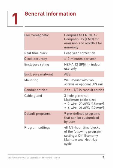
Electromagnetic Complies to EN 5014-1 Compatibility (EMC) for emission and 60730-1 for immunity
Real time clock Leap year correction
Clock accuracy ±10 minutes per year
Enclosure rating NEMA 12 (IP54) – indoor use only
Enclosure material ABS
Mounting Wall mount with two screws or optional DIN rail
Conduit entries 2 ea – 1/2 in conduit entries
Cable gland 3-hole grommet Maximum cable size:• 2-wire: 20 AWG (0.5 mm2)• 4-wire: 24 AWG (0.2 mm2)
Default programs 9 pre-defined programs that can be customized by user
Program settings 48 1/2-hour time blocks of the following program settings: Off, Economy, Maintain and Heat-Up cycle

1 General Information
6 EN-RaychemHWATECOcontroller-IM-H57340 03/13
Password 4-digit password protection
Master/slave Master is selectable in the controller, up to 8 slaves can be connected
Master/slave cable 2-wire, min. 24 AWG (0.2 mm2) twisted pair and insulation of 300 V, Max length cable is 100 m
Parameters in memory All parameters are stored in nonvolatile memory, except time and date
Clock backup time Rechargable Lithium bat-tery. Battery will retain time and date for up to 30 days when power is lost
Approvals80BJ
Type 12Energy Management Equipment(for use with HWAT-R2 and HWAT-Y2 heating cables only.)
Weight 2 lbs (1 kg)
Size 6.5 in x 3.4 in x 2.8 in (165 mm x 85 mm x 71 mm)
1 General Information
7EN-RaychemHWATECOcontroller-IM-H57340 03/13
1.4 Care and MaintenanceTo clean the HWAT-ECO use a damp cloth. Do not use solvents. Do not pour water directly on the device. Do not use a water hose or high pressure cleaner.
Important: In case of questions or product failure, please contact your Pentair Thermal Management rep-resentative, or call Pentair Thermal Management at 800-545-6258.
1.5 HWAT Heating Cables
Maintain temperatureDepending on the ambient temperature and voltage, HWAT-Y2 is designed to maintain temperatures up to 125˚F (52˚C), and HWAT-R2 is designed to maintain temperatures up to 140˚F (60˚C).
Installing the heating cables Install the HWAT heating cable system as instructed in the HWAT System Installation and Operation Manual (H57548). The controller must be installed by a professional electrical installer familiar with elec-trical safety codes and practices.
1 General Information
8 EN-RaychemHWATECOcontroller-IM-H57340 03/13
Ground-fault protection
WARNING: To minimize the danger of fire from sustained electrical arcing if the heating cable is damaged or improperly installed, and to comply with the requirements of approvals agencies, Pentair Thermal Management and national electrical codes, ground-fault equipment protection must be used on each heating cable branch circuit. Arcing may not be stopped by conventional circuit protection. The HWAT-ECO does not include ground-fault protection.
Pre-Installation testingPrior to installing the HWAT-ECO controller, perform the insulation resistance (Megger) test and circuit length verification (Capacitance) test on the heating cable as detailed in the HWAT System Installation and Operation Manual (H57548).
2 Installation
9EN-RaychemHWATECOcontroller-IM-H57340 03/13
2.1 Installing the ControllerInstall the controller in an indoor, dry, clean, acces-sible location. If using the optional pipe temperature sensor, make sure you install the controller within 328 ft (100 m) of where you want to monitor the pipe temperature.
Opening the controller
WARNING: To prevent shock, always switch off the power supply (circuit breaker) before opening the controller.
The HWAT-ECO has a removable front cover. Both the cover and the box have electronic parts and are connected to each other by a 14-pin connector. First unscrew the four screws in the cover. Carefully pull the cover straight out, not sideways!
2 Installation
10 EN-RaychemHWATECOcontroller-IM-H57340 03/13
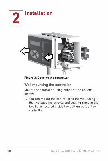
Figure 3: Opening the controller
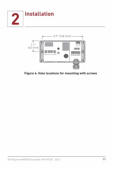
Wall mounting the controllerMount the controller using either of the options below: 1. You can mount the controller to the wall using
the two supplied screws and sealing rings in the two holes located inside the bottom part of the controller.
2 Installation
11EN-RaychemHWATECOcontroller-IM-H57340 03/13
5.9" (148 mm)
1.7"(43 mm)
TEMP BMSB A
Figure 4: Hole locations for mounting with screws

2 Installation
12 EN-RaychemHWATECOcontroller-IM-H57340 03/13
2. Optionally you can mount the controller using DIN 35 Rail mounting.
Optional Din Rail Mount(Rail not provided)
Mounting
Removing
Press tab to remove box
Figure 5: Mounting with DIN 35 Rail
2 Installation
13EN-RaychemHWATECOcontroller-IM-H57340 03/13
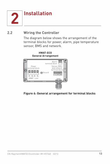
2.2 Wiring the ControllerThe diagram below shows the arrangement of the terminal blocks for power, alarm, pipe temperature sensor, BMS and network.
Ground
HWAT-ECOGeneral Arrangement
Powerterminal block
Sensor, BMS,and network
terminal block
Alarmterminal block
Ø1 Ø2HWAT Line
Ø1 Ø2TEMP BMSB A
Figure 6: General arrangement for terminal blocks
2 Installation
14 EN-RaychemHWATECOcontroller-IM-H57340 03/13
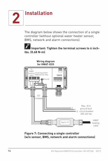
The diagram below shows the connection of a single controller (without optional water heater sensor, BMS, network and alarm connections).
Important: Tighten the terminal screws to 6 inch-lbs. (0.68 N-m)
ØØ
G
1/2"Conduits
HWATheatingcable
RayClic-PC
Max. 30 A ground fault
circuit breaker208-240 Vac
Ground
Incoming power208/240 Vac Max
Wiring diagramfor HWAT-ECO
ToHWAT
heatingcable
TEMP BMSB A
Figure 7: Connecting a single controller (w/o sensor, BMS, network and alarm connections)
2 Installation
15EN-RaychemHWATECOcontroller-IM-H57340 03/13
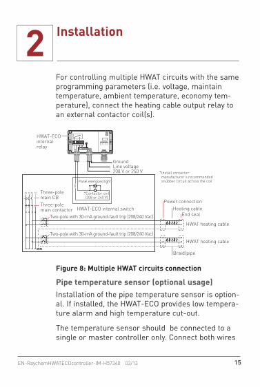
For controlling multiple HWAT circuits with the same programming parameters (i.e. voltage, maintain temperature, ambient temperature, economy tem-perature), connect the heating cable output relay to an external contactor coil(s).
Nø1
HWAT-ECO internal switch
ø3ø2
HWAT heating cable
HWAT heating cable
Braid/pipe
Two-pole with 30-mA ground-fault trip (208/240 Vac)
Two-pole with 30-mA ground-fault trip (208/240 Vac)
Three-polemain CB
HWAT-ECOinternalrelay
Power connection
Panel energized light
*Contactor coil(208 or 240 V)
Heating cableEnd seal
Three-polemain contactor
GroundLine voltage208 V or 240 V Install contactor
manufacturer’s recommended snubber circuit across the coil
*
Figure 8: Multiple HWAT circuits connection
Pipe temperature sensor (optional usage)Installation of the pipe temperature sensor is option-al. If installed, the HWAT-ECO provides low tempera-ture alarm and high temperature cut-out.
The temperature sensor should be connected to a single or master controller only. Connect both wires

2 Installation
16 EN-RaychemHWATECOcontroller-IM-H57340 03/13
of the temperature sensor to the TEMP terminal in the controller (PL4). The sensor wires do not have a special polarity. To connect a wire, use a screw-driver to push down the orange tab on the side of the terminal. Put the wire into the hole and release the orange tab.
PL4PL3 PL5Standard temperature sensor
PT100 sensor (2 wire)
shortfor
PT100
TEMP BMSB A
PL4PL3 PL5
TEMP BMSB A
Alarm,Sensor,
and BMS terminals PL6 Al
arm
con
tact
TEMP BMSB A
Figure 9: TEMP terminal location and sensor wiring
Optionally, PT100 RTDs from the water heater can be used. To install a PT100 sensor first connect a jumper between the terminals indicated in Figure 9, then connect the two wires from the RTD. If you are using a three wire sensor, remove the compensation lead and only connect the two measurement wires.

2 Installation
17EN-RaychemHWATECOcontroller-IM-H57340 03/13
The pipe temperature sensor must be placed on 1-inch diameter pipes or larger, installed opposite from the HWAT heating cable to accurately measure the pipe temperature.
The temperature sensor cable is 13 ft 3 in (4 m) in length, however the user can extend the cable up to 328 ft (100 m) by splicing a length of 300 volt, 18 AWG (0.75 mm2) cable.
Cold water in
mixingvalve
Tempered water out
Hot water out
Hot water in
HWAT-Y2HWAT-R2
Waterheater
A B
Temperaturesensor
Insulation
180°Heatingcable
Figure 10: Positioning temperature sensor (optional)
2 Installation
18 EN-RaychemHWATECOcontroller-IM-H57340 03/13
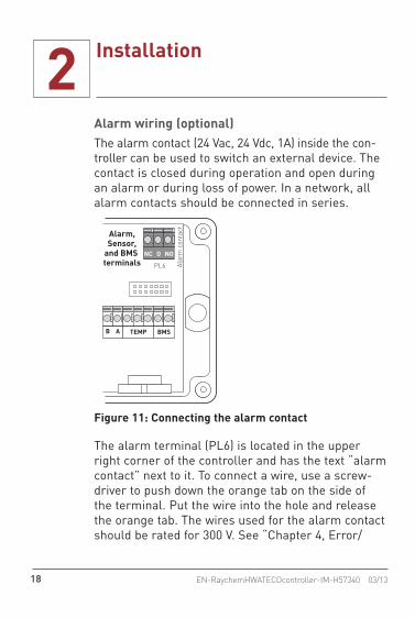
Alarm wiring (optional) The alarm contact (24 Vac, 24 Vdc, 1A) inside the con-troller can be used to switch an external device. The contact is closed during operation and open during an alarm or during loss of power. In a network, all alarm contacts should be connected in series.
Alarm,Sensor,
and BMS terminals PL6 Al
arm
con
tact
TEMP BMSB A
NC O NO
Figure 11: Connecting the alarm contact
The alarm terminal (PL6) is located in the upper right corner of the controller and has the text “alarm contact” next to it. To connect a wire, use a screw-driver to push down the orange tab on the side of the terminal. Put the wire into the hole and release the orange tab. The wires used for the alarm contact should be rated for 300 V. See “Chapter 4, Error/

2 Installation
19EN-RaychemHWATECOcontroller-IM-H57340 03/13
Alarms and Troubleshooting” for more information about alarm conditions.
The alarm contact is designed as a fail safe mode and can be wired for normally open (NO) or normally closed (NC) operation. The following table summa-rizes the relay positions in the different controller states:
Position NC NO
Power Off Open Closed
Power On Closed Open
Alarm Mode Open Closed
NetworkThe Master/slave function allows one HWAT-ECO to control up to eight additional HWAT-ECO controllers. Connect all HWAT-ECO controllers to each other in parallel using the A and B inputs on terminal (PL3). This means that several controllers will have two wires in one hole. The wire should be a twisted pair and be rated for 300 V. The total maximum length of this cable between all controllers is 328 ft (100 m). Be careful not to mix A and B connections. To connect a wire, use a screwdriver to push down the orange tab on the side of the terminal. Put the wire into the hole and release the orange tab.
2 Installation
20 EN-RaychemHWATECOcontroller-IM-H57340 03/13
MASTERTEMP BMSB ATEMP BMSB A
SLAVE 1
OPTI
ONAL
BM
S
WAT
ER H
EATE
R SE
NSOR
NETW
ORK
WIR
E
TO
SLA
VE 2
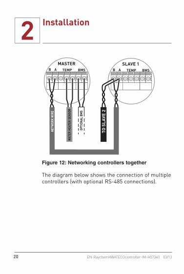
Figure 12: Networking controllers together
The diagram below shows the connection of multiple controllers (with optional RS-485 connections).

2 Installation
21EN-RaychemHWATECOcontroller-IM-H57340 03/13
HWATheatingcable
LL 208/240V
HWATheatingcable
Master Slave 1 Slave 2
RS-485 RS-485
Sensor
BMS
Alarm
L L208/240V
LL 208/240V
HWATheatingcable
Figure 13: Connecting multiple controllers (with RS-485)
When multiple controllers are networked and you are using BMS and Alarm functions, you must use a 4-wire conductor.
max. 20 AWG (0.5 mm2)
max. 24 AWG (0.2 mm2)
Figure 14: Combine alarm and BMS wire in 4-wire cable
Important: For master/slave combination with alarm function, the alarms are connected in series by a RS485 wire. Since the cable gland grommet has only 3 holes, you must combine the alarm wire and the BMS wire in a 4-wire cable.
2 Installation
22 EN-RaychemHWATECOcontroller-IM-H57340 03/13
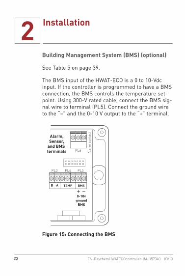
Building Management System (BMS) (optional)
See Table 5 on page 39.
The BMS input of the HWAT-ECO is a 0 to 10-Vdc input. If the controller is programmed to have a BMS connection, the BMS controls the temperature set-point. Using 300-V rated cable, connect the BMS sig-nal wire to terminal (PL5). Connect the ground wire to the “–” and the 0-10 V output to the “+” terminal.
Alarm,Sensor,
and BMS terminals
0-10vground
BMS
PL3 PL5PL4
PL6 Alar
m c
onta
ct
TEMP BMSB A
Figure 15: Connecting the BMS
2 Installation
23EN-RaychemHWATECOcontroller-IM-H57340 03/13
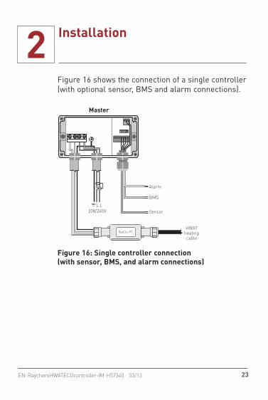
Figure 16 shows the connection of a single controller (with optional sensor, BMS and alarm connections).
Master
HWATheatingcable
Sensor
BMS
Alarm
L L208/240V
RayClic-PC
Figure 16: Single controller connection (with sensor, BMS, and alarm connections)

2 Installation
24 EN-RaychemHWATECOcontroller-IM-H57340 03/13
Closing the controllerPosition the cover in front of the wall-mounted box. The separation sheet inside the controller will help guide the cover and the connector. Push the cover onto the box. Note that the connector pins will offer some resistance. Put the screws in place and tighten to 10 inch-lbs (1.13 N-m).
Figure 17: Closing the controller
2 Installation
25EN-RaychemHWATECOcontroller-IM-H57340 03/13
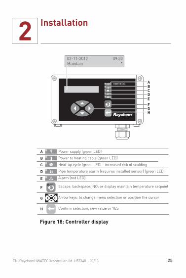
Power supply (green LED)
Power to heating cable (green LED)
Heat-up cycle (green LED) - increased risk of scalding
Pipe temperature alarm (requires installed sensor) (green LED)
Alarm (red LED)
Escape, backspace; NO; or display maintain temperature setpoint
Arrow keys: to change menu selection or position the cursor
Confirm selection, new value or YES
02-11-2012 09:30Maintain *
ABCDEFGH
A
B
C
D
E
F
G
H
Figure 18: Controller display
3 Programming the Controller
26 EN-RaychemHWATECOcontroller-IM-H57340 03/13
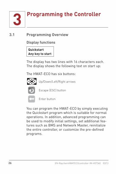
3.1 Programming Overview
Display functions
QuickstartAny key to start
The display has two lines with 16 characters each. The display shows the following text on start up:
The HWAT-ECO has six buttons:
Up/Down/Left/Right arrows
Escape (ESC) button
Enter button
You can program the HWAT-ECO by simply executing the Quickstart program which is suitable for normal operations. In addition, advanced programming can be used to modify initial settings, set additional fea-tures such as BMS and Network Master, reinitialize the entire controller, or customize the pre-defined programs.

3 Programming the Controller
27EN-RaychemHWATECOcontroller-IM-H57340 03/13
3.2 Initializing the ControllerThe first time you power up the controller, you must execute the Quickstart program to set the initial set-tings. Once initialized continue to power the control-ler for at least 6 hours to charge the internal battery.
TABLE 1: QUICKSTART MENU
Time and date YearMonthDayHourMinutes
Select YearSelect MonthSelect DaySelect HourSelect Minutes
Cable type HWAT-R2 “Press Enter for this cable type.”
HWAT-Y2 “Press Enter for this cable type.”
Voltage select 208 Vac “Press Enter for this voltage type.”
240 Vac “Press Enter for this voltage type.”
Units English “Press Enter for this unit type.”
Metric “Press Enter for this unit type.”
Ambient temp.Maintain temp.Economy temp.
“Enter ambient temp.”“Enter maintain temp. setpoint”“Enter economy temp. setpoint”

3 Programming the Controller
28 EN-RaychemHWATECOcontroller-IM-H57340 03/13
TABLE 1: QUICKSTART MENU
Default program ConstantApartmentsFamily homePrisonHospitalNursing homeHotelSports centerConvales. home
“Scroll to program and press Enter.”
During the Quickstart you can press the ESC button to go back to a previous menu. On startup the dis-play will show the following text:
QuickstartAny key to start
Press a key to start, and the following menus appear:
Time and DateUse the up/down arrows to select the year and press Enter. Then, select and enter the month, day, hour, and minutes. The time and date is contained in vola-tile memory, and is maintained during power out-ages by an internal rechargeable battery. Power the HWAT-ECO for at least 6 hours to charge the battery.
3 Programming the Controller
29EN-RaychemHWATECOcontroller-IM-H57340 03/13
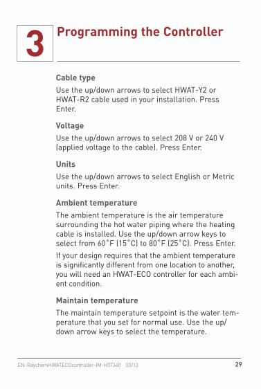
Cable typeUse the up/down arrows to select HWAT-Y2 or HWAT-R2 cable used in your installation. Press Enter.
VoltageUse the up/down arrows to select 208 V or 240 V (applied voltage to the cable). Press Enter.
UnitsUse the up/down arrows to select English or Metric units. Press Enter.
Ambient temperatureThe ambient temperature is the air temperature surrounding the hot water piping where the heating cable is installed. Use the up/down arrow keys to select from 60˚F (15˚C) to 80˚F (25˚C). Press Enter. If your design requires that the ambient temperature is significantly different from one location to another, you will need an HWAT-ECO controller for each ambi-ent condition.
Maintain temperatureThe maintain temperature setpoint is the water tem-perature that you set for normal use. Use the up/down arrow keys to select the temperature.
3 Programming the Controller
30 EN-RaychemHWATECOcontroller-IM-H57340 03/13
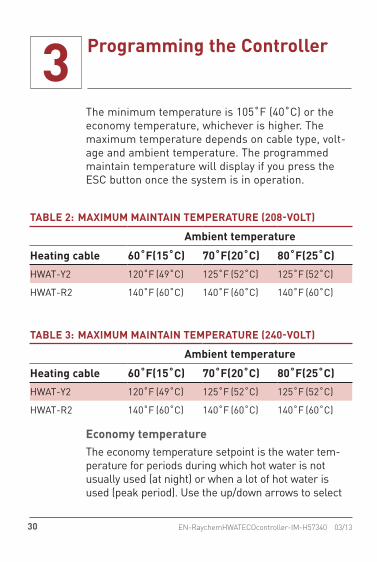
The minimum temperature is 105˚F (40˚C) or the economy temperature, whichever is higher. The maximum temperature depends on cable type, volt-age and ambient temperature. The programmed maintain temperature will display if you press the ESC button once the system is in operation.
TABLE 2: MAXIMUM MAINTAIN TEMPERATURE (208-VOLT)
Ambient temperature
Heating cable 60˚F (15˚C) 70˚F (20˚C) 80˚F (25˚C)
HWAT-Y2 120˚F (49˚C) 125˚F (52˚C) 125˚F (52˚C)
HWAT-R2 140˚F (60˚C) 140˚F (60˚C) 140˚F (60˚C)
TABLE 3: MAXIMUM MAINTAIN TEMPERATURE (240-VOLT)
Ambient temperature
Heating cable 60˚F (15˚C) 70˚F (20˚C) 80˚F (25˚C)
HWAT-Y2 120˚F (49˚C) 125˚F (52˚C) 125˚F (52˚C)
HWAT-R2 140˚F (60˚C) 140˚F (60˚C) 140˚F (60˚C)
Economy temperatureThe economy temperature setpoint is the water tem-perature for periods during which hot water is not usually used (at night) or when a lot of hot water is used (peak period). Use the up/down arrows to select

3 Programming the Controller
31EN-RaychemHWATECOcontroller-IM-H57340 03/13
the temperature. The minimum temperature is 105˚F (40˚C) and the maximum temperature is the selected maintain temperature.
Default programsThe HWAT-ECO has 9 pre-defined programs. (See “Chapter 5, Pre-Defined Programs” for more infor-mation.) Use the up/down arrows to select a pre-defined program. Press Enter. HWAT-ECO takes a few seconds to copy the pre-defined program to the internal memory. During this time a row of dots will show in the display.
Pipe temperatureThis function also ensures that the delivered water temperature is not lower than the desired maintain temperature.
Completing initializationThe controller will start automatically when you finish selecting your Quickstart options. Additional settings are available in the Setup menu for advanced installations. See section 3.3 on page 33 for more information.
Press Enter to start the controller. If you press the ESC button, you can retrace all menu items to check the settings. After starting the controller the display shows date, time, temperature setting and a “*” to

3 Programming the Controller
32 EN-RaychemHWATECOcontroller-IM-H57340 03/13
indicate that the controller is unlocked. If you wish to lock (password protect) the controller, see section 3.3.2.6 for instructions.
Displaying Maintain Temperature SetpointAfter finishing the Quickstart, the display will show the date, time, temperature mode and a star to indi-cate that the controller is unlocked.
02-11-2013Maintain
09:13
While in operating mode, press ESC to view a bar graph that shows the maintain temperature setpoint. To enter the programming menu, press any other key. The controller will exit the menu automatically after five seconds of key inactivity.
Figure 19: Bar graph
Displaying Pipe TemperatureWhen the optional pipe temperature sensor is con-nected, the controller will display date and time as above and alternate between temperature mode and pipe temperature.

3 Programming the Controller
33EN-RaychemHWATECOcontroller-IM-H57340 03/13
02-11-2013Pipe T: 110°F
09:13*
3.3 Advanced ProgrammingAdvanced programming options are also available. Table 4 and the remainder of this section outline the advanced programming options that include modify-ing initial settings, setting additional features such as BMS and Network Master, reinitializing the entire controller, or customizing the pre-defined programs.

3 Programming the Controller
34 EN-RaychemHWATECOcontroller-IM-H57340 03/13
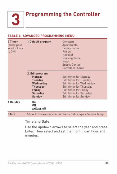
TABLE 4: ADVANCED PROGRAMMING MENU
1 Time and Date
1 Year2 Month3 Day4 Hour5 Minutes
Select YearSelect MonthSelect DaySelect HourSelect Minutes
2 Setup(enter pass-word if Lock is ON)
1 Main Temp “Enter maintain temp. setpoint”
2 Economy Temp “Enter economy temp. setpoint”
3 Ambient Temp “Enter ambient temp.”
4 Power Correction Selectable
5 Lock Lock/unlock Setup and Timer menus
6 BMS Select Yes/No
7 Network Master Select Yes/No
8 Reinitialize Select Yes/No
9 Short heater Select Yes/No
10 LTA(Low Temp Alarm)1. Set Status2. Set Temperature3. Set Alarm Filter Time4. Set Deadband
Select Yes/NoEnabled or Disabled95°F (35°C) min5-30 Minutes4-18°F (2-10°C)
11 HTC(High Tem. Cut Out)1. Set Status2. Set Temperature3. Set Alarm Filter Time4. Set Deadband
Enabled or DisabledMaximum 205°F10-30 Minutes4-18°F (2-10°C)
3 Programming the Controller
35EN-RaychemHWATECOcontroller-IM-H57340 03/13
TABLE 4: ADVANCED PROGRAMMING MENU
3 Timer(enter pass-word if Lock is ON)
1 Default program ConstantApartmentsFamily homePrisonHospitalNursing homeHotelSports CenterConvalesc. home
2. Edit programMondayTuesdayWednesdayThursdayFridaySaturdaySunday
Edit timer for MondayEdit timer for TuesdayEdit timer for WednesdayEdit timer for ThursdayEdit timer for FridayEdit timer for SaturdayEdit timer for Sunday
4 Holiday OnOffxxDays off
5 Info Show firmware version number + Cable type + Sensor temp.
Time and DateUse the up/down arrows to select the year and press Enter. Then select and set the month, day, hour and minutes.
3 Programming the Controller
36 EN-RaychemHWATECOcontroller-IM-H57340 03/13
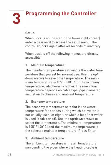
SetupWhen Lock is on (no star in the lower right corner) enter a password to access the setup menu. The controller locks again after 60 seconds of inactivity.
When Lock is off the following menus are directly accessible.
1. Maintain temperature The maintain temperature setpoint is the water tem-perature that you set for normal use. Use the up/down arrows to select the temperature. The mini-mum temperature is 105˚F (40˚C) or the economy temperature, whichever is higher. The maximum temperature depends on cable type, pipe diameter, insulation thickness and ambient temperature.
2. Economy temperatureThe economy temperature setpoint is the water temperature for periods during which hot water is not usually used (at night) or when a lot of hot water is used (peak period). Use the up/down arrows to select the temperature. The minimum temperature is 105˚F (40˚C) and the maximum temperature is the selected maintain temperature. Press Enter.
3. Ambient temperatureThe ambient temperature is the air temperature surrounding the pipes where the heating cable is

3 Programming the Controller
37EN-RaychemHWATECOcontroller-IM-H57340 03/13
installed. Use the up/down arrows to select from 60˚F (15˚C) to 80˚F (25˚C). Press Enter to confirm. If your design requires that the ambient temperature is significantly different from one location to another, you will need an HWAT-ECO controller for each ambient condition.
4. Power correction The power correction factor can be selected to increase or decrease your actual pipe maintain tem-perature or to adjust for using HWAT heating cables on rigid plastic pipes.The power correction factor can be adjusted from 0.6 to 1.40, increasing or decreasing the percent time the heating cable is powered during the duty cycle.For installation on rigid plastic pipe set the power factor at:
HWAT-Y2: 1.20HWAT-R2: 1.25
5. Lock (password)Use the up/down arrows to select Lock On/Off and press Enter. If you select ‘On’, you must enter a password using the left/right and up/down arrow buttons to select a 4-digit password. Press Enter.You will need to remember your 4-digit password whenever you wish to unlock the controller for

3 Programming the Controller
38 EN-RaychemHWATECOcontroller-IM-H57340 03/13
reprogramming. Once you unlock and reprogram, you will need to relock by entering your password.If Lock is On, the Setup and Timer menus are pro-tected by the password. After you enter the pass-word, the controller remains unlocked until five minutes of key inactivity or until you select Lock ‘On’ again.
6. Building Management System (BMS)You can activate the Building Management System option using this menu. When set to “Yes” the control-ler responds only to the voltage applied to the BMS terminal. For voltages ≤ 4 Vdc: heating cable is OFF. For voltages between 4.1 Vdc and 6.4 Vdc: maintain temperatures are set as indicated in Table 5. For voltages > 6.4 Vdc: 100% power is applied to the heating cable. See "Building Management System (BMS) (optional)" on page 22 for installation infor-mation. If Water heater is ON, it overrules the BMS temperature setting if necessary.
3 Programming the Controller
39EN-RaychemHWATECOcontroller-IM-H57340 03/13
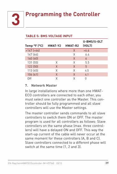
TABLE 5: BMS VOLTAGE INPUT
Temp °F (°C) HWAT-Y2 HWAT-R2U-BMS/U-GLT (VOLT)
>147 (>64) X >6.4 147 (64) X 6.4 140 (60) X 6 131 (55) X X 5.5 122 (50) X X 5 113 (45) X X 4.5 106 (41) X X 4.1 Off X X 0
7. Network MasterIn large installations where more than one HWAT-ECO controllers are connected to each other, you must select one controller as the Master. This con-troller should be fully programmed and all slave controllers will use the Master settings.The master controller sends commands to all slave controllers to switch them ON or OFF. The master program is used for all controllers as follows: Slave controllers on the same phase (max. three control-lers) will have a delayed ON and OFF. This way the start-up current of the cable will never occur at the same moment for these controllers (A, B and C). Slave controllers connected to a different phase will switch at the same time (1, 2 and 3).

3 Programming the Controller
40 EN-RaychemHWATECOcontroller-IM-H57340 03/13
After selecting “Master: Yes”, the slave controllers will initialize and show: :Slave: “x y” x= phase number (1 to 3) y= slave identification (A, B and C)The master controller is always 1 A, the slave con-trollers will get their number and identification auto-matically. Always check afterwards if all controllers have unique id-numbers, if not, check the RS485 cables and repeat this procedure.
8. ReinitializeTo Reinitialize all settings back to the factory set-tings (except time and date), set the “Reinitialize” menu to “Yes.”
9. Short HeaterThis feature allows you to activate a low current alarm:Yes: Allows low current such as when used as a demonstration, or to control a contactor. In this mode there is no low current alarm.No: Generates low current alarm when measured current is less that 300 mA.
10. LTA (Low Pipe Temperature Alarm)When the optional pipe temperature sensor option is installed, the HWAT-ECO controller monitors the temperature of the hot water distribution pipes

3 Programming the Controller
41EN-RaychemHWATECOcontroller-IM-H57340 03/13
where the sensor is installed and can generate a low pipe temperature alarm.1. Set Status: Enabled or Disabled2. Set temperature:
– Minimum: 95°F (35°C) – Maximum: < Maintain (or Economy)
3. Set Alarm filter time: 5–30 minutes4. Set deadband: 4–18°F (2–10°C), 9°F
(5°C default)
11. HTC (High Temperature Cut-Out)When the optional pipe temperature sensor option is installed, the HWAT-ECO controller monitors the temperature of the hot water distribution pipes where the sensor is installed and a high temperature cut-out can be set.High Temperature Cut-out:
Minimum: > set pointMaximum: 205°F (96°C)Alarm filter: 5–30 minutes (default 10)Dead band: > 5°F (3°C) default 0°F(6°C)
Timer The Timer feature lets you re-program any of the pre-defined programs to suit your personnel requirements. Reprogramming is done graphically in 1/2 hour time blocks. A block can be set to Heat-Up

3 Programming the Controller
42 EN-RaychemHWATECOcontroller-IM-H57340 03/13
cycle, Maintain temperature, Economy temperature, or Off. See “Chapter 6, Heat-Up Cycle Graphs” for more information.
Edit pre-defined programsTo edit a program, switch Lock to Off. If password protected, you will need to enter the password to unlock the controller. After you enter the password, the controller remains unlocked until five minutes of key inactivity or the Lock ‘On’ is selected again
Select temperatureUse the up/down arrows to select the temperature:
= Maintain temperature= Heat-up cycle
= Economy temperature = Off
Figure 20: Timer block options
Select time blockUse the left/right arrows to select the time block. Timer programming example from 00:00 to 08:00:
3 Programming the Controller
43EN-RaychemHWATECOcontroller-IM-H57340 03/13
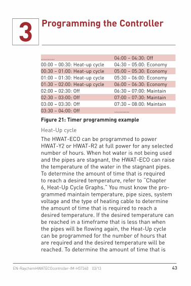
.......... 04:00 – 04:30: Off00:00 – 00:30: Heat-up cycle 04:30 – 05:00: Economy00:30 – 01:00: Heat-up cycle 05:00 – 05:30: Economy01:00 – 01:30: Heat-up cycle 05:30 – 06:00: Economy01:30 – 02:00: Heat-up cycle 06:00 – 06:30: Economy02:00 – 02:30: Off 06:30 – 07:00: Maintain02:30 – 03:00: Off 07:00 – 07:30: Maintain03:00 – 03:30: Off 07:30 – 08:00: Maintain03:30 – 04:00: Off ...........
Figure 21: Timer programming example
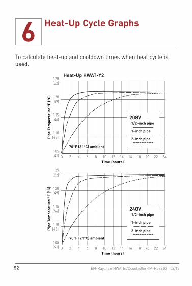
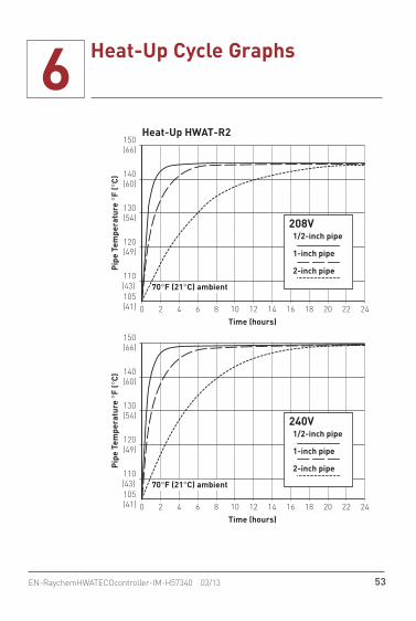
Heat-Up cycleThe HWAT-ECO can be programmed to power HWAT-Y2 or HWAT-R2 at full power for any selected number of hours. When hot water is not being used and the pipes are stagnant, the HWAT-ECO can raise the temperature of the water in the stagnant pipes. To determine the amount of time that is required to reach a desired temperature, refer to “Chapter 6, Heat-Up Cycle Graphs.” You must know the pro-grammed maintain temperature, pipe sizes, system voltage and the type of heating cable to determine the amount of time that is required to reach a desired temperature. If the desired temperature can be reached in a timeframe that is less than when the pipes will be flowing again, the Heat-Up cycle can be programmed for the number of hours that are required and the desired temperature will be reached. To determine the amount of time that is

3 Programming the Controller
44 EN-RaychemHWATECOcontroller-IM-H57340 03/13
required to return back to the maintain temperature after the Heat-Up cycle is complete and the heating cable is off, refer to “Chapter 7, Cool-Down Graph.”
HolidayThis menu is used to set the controller to Off, timed-off, or to resume your timer program.
On: The controller uses the normal operation the timer program.Off: The controller will not power the system until you select “Use timer”.
xx Days off: You can select a number of days. The controller automatically returns to timer mode when the selected number of days have passed.
InfoThe display shows the firmware version number, selected cable type and the current sensor tempera-ture. Press Enter twice to update the sensor tem-perature on the display.

4 Error/Alarms and Troubleshooting
45EN-RaychemHWATECOcontroller-IM-H57340 03/13
Please ensure that the unit is correctly connected to the power supply and the heating cable is connected to the HWAT-ECO unit.
Error code Definitions Cause/reasons Remedy
Error 1: Internal temperature alarm;Temperature is too high. (> 65°C)
Turn off power and allow the controller to cool and then re-energize. The controller will lock out after three occur-rences. If this does not restore the controller, replace the HWAT-ECO.
Error 2: Pipe Sensor failure(Only when tempera-ture alarm “enabled” selected)• Sensor or sensor
cable defect• Low temp alarm or
High temperature cut-out selected and sensor is not installed.
Connect sensor to HWAT-ECO or turn off temperature alarm.Check sensor connections; replace sensor, check tempera-ture sensor mounting
Error 3: Network failureTwo or more HWAT-ECO’s are set as Master
Reinitialize MASTER (see "Setup" on page 36)

4 Error/Alarms and Troubleshooting
46 EN-RaychemHWATECOcontroller-IM-H57340 03/13
Error code Definitions Cause/reasons Remedy
Error 4: Internal Error Controller needs to be replaced. Contact Pentair Thermal Management representative
Error 5: No/Low current alarm Ensure that the heating circuit is connected to power output of the HWAT-ECO. If controlling a contactor, ensure that the Short Heater Alarm is enabled.
Error 6: Configuration Error Refer to "Short Heater" menu.• If heating cable is longer
that 15 ft. (4.5 m) then, Short heater = No
• If heating cable is shorter than 15 ft. (4.5 m) then, Short heater = Yes
Error 7: Pipe temperature too high (Only when HTC is enabled)• Boiler temperature is
too high.• Pipe temperature
too hot
• Verify High Temperature Cut-out (HTC) is set correctly.
• Correct boiler or mixing valve setting.
• Verify HWAT-ECO programming.
• Verify that pipe insulation schedule is correct.
4 Error/Alarms and Troubleshooting
47EN-RaychemHWATECOcontroller-IM-H57340 03/13
Error code Definitions Cause/reasons Remedy
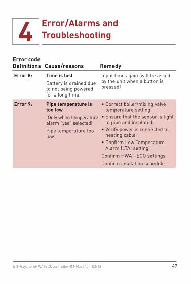
Error 8: Time is lostBattery is drained due to not being powered for a long time.
Input time again (will be asked by the unit when a button is pressed)
Error 9: Pipe temperature is too low(Only when temperature alarm “yes” selected)Pipe temperature too low
• Correct boiler/mixing valve temperature setting
• Ensure that the sensor is tight to pipe and insulated.
• Verify power is connected to heating cable.
• Confirm Low Temperature Alarm (LTA) setting
Confirm HWAT-ECO settingsConfirm insulation schedule

4 Error/Alarms and Troubleshooting
48 EN-RaychemHWATECOcontroller-IM-H57340 03/13
Indications/Trouble shooting Cause/reasons Remedy
Water temperature too low
Too low water temperature• Boiler temperature is
too low• Cold water entering
system• Heater used is differ-
ent type than entered in program.
• Entered value of ambient temperature is too high.
• Insulation thickness is different than stan-dard thickness.
• Check boiler tem-perature and timer program
• Mixing valves and janitor sinks may be allowing cold water to cross over to the hot water side.
• Change heater type in HWAT-ECO (can only be done in quick install "Setup" on page 36 - Reinitialize)
• Change value of ambient temperature
• Adjust power correc-tion factor if possible (see "Timer" on page 41)
• Change insulation to match required schedule in HWAT installation manual.
4 Error/Alarms and Troubleshooting
49EN-RaychemHWATECOcontroller-IM-H57340 03/13
Indications/Trouble shooting Cause/reasons Remedy
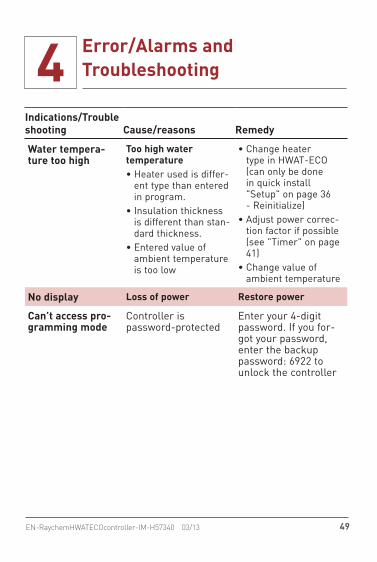
Water tempera-ture too high
Too high water temperature• Heater used is differ-
ent type than entered in program.
• Insulation thickness is different than stan-dard thickness.
• Entered value of ambient temperature is too low
• Change heater type in HWAT-ECO (can only be done in quick install "Setup" on page 36 - Reinitialize)
• Adjust power correc-tion factor if possible (see "Timer" on page 41)
• Change value of ambient temperature
No display Loss of power Restore power
Can’t access pro-gramming mode
Controller is password-protected
Enter your 4-digit password. If you for-got your password, enter the backup password: 6922 to unlock the controller
5 Pre-Defined Programs
50 EN-RaychemHWATECOcontroller-IM-H57340 03/13
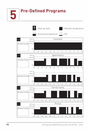
ConstantI-0
Monday-Sunday
ApartmentsI-1
Monday-Friday
Saturday-Sunday
Family homeI-2
Monday-Sunday
PrisonI-3
Monday-Sunday
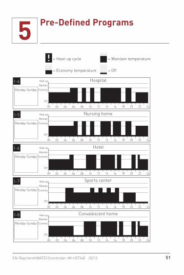
HospitalI-4
Monday-Sunday
Nursing homeI-5
Monday-Sunday
HotelI-6
Monday-Sunday
Sports centerI-7
Monday-Sunday
Convalescent homeI-8
Monday-Sunday
00 06 12 18 2402 04 16141008 20 22
00 06 12 18 2402 04 16141008 20 22
00 06 12 18 2402 04 16141008 20 22
00 06 12 18 2402 04 16141008 20 22
00 06 12 18 2402 04 16141008 20 22
00 06 12 18 2402 04 16141008 20 22
Heat-up
EconomyMaintain
Heat-up
Economy
Maintain
Heat-up
Economy
Maintain
00 06 12 18 2402 04 16141008 20 22
Heat-up
Economy
Maintain
00 06 12 18 2402 04 16141008 20 22
Heat-up
Off
Economy
Maintain
= Maintain temperature= Heat-up cycle
= Economy temperature = Off
= Maintain temperature= Heat-up cycle
= Economy temperature = Off
Heat-up
EconomyMaintain
Heat-up
Economy
Maintain
Heat-up
Economy
Maintain
00 06 12 18 2402 04 16141008 20 22
Heat-up
Economy
Maintain
00 06 12 18 2402 04 16141008 20 22
Heat-up
Economy
Maintain
Off
Off
Off
Off Off
Off
Off
Off
Off
5 Pre-Defined Programs
51EN-RaychemHWATECOcontroller-IM-H57340 03/13
ConstantI-0
Monday-Sunday
ApartmentsI-1
Monday-Friday
Saturday-Sunday
Family homeI-2
Monday-Sunday
PrisonI-3
Monday-Sunday
HospitalI-4
Monday-Sunday
Nursing homeI-5
Monday-Sunday
HotelI-6
Monday-Sunday
Sports centerI-7
Monday-Sunday
Convalescent homeI-8
Monday-Sunday
00 06 12 18 2402 04 16141008 20 22
00 06 12 18 2402 04 16141008 20 22
00 06 12 18 2402 04 16141008 20 22
00 06 12 18 2402 04 16141008 20 22
00 06 12 18 2402 04 16141008 20 22
00 06 12 18 2402 04 16141008 20 22
Heat-up
EconomyMaintain
Heat-up
Economy
Maintain
Heat-up
Economy
Maintain
00 06 12 18 2402 04 16141008 20 22
Heat-up
Economy
Maintain
00 06 12 18 2402 04 16141008 20 22
Heat-up
Off
Economy
Maintain
= Maintain temperature= Heat-up cycle
= Economy temperature = Off
= Maintain temperature= Heat-up cycle
= Economy temperature = Off
Heat-up
EconomyMaintain
Heat-up
Economy
Maintain
Heat-up
Economy
Maintain
00 06 12 18 2402 04 16141008 20 22
Heat-up
Economy
Maintain
00 06 12 18 2402 04 16141008 20 22
Heat-up
Economy
Maintain
Off
Off
Off
Off Off
Off
Off
Off
Off
6 Heat-Up Cycle Graphs
52 EN-RaychemHWATECOcontroller-IM-H57340 03/13
To calculate heat-up and cooldown times when heat cycle is used.
Heat-Up HWAT-Y2125(52)
120(49)
115(46)
110(43)
Time (hours)
Pipe
Tem
pera
ture
°F
(°C)
105(41) 0 2 4 6 8 10 12 14 16 18 22 2420
70°F (21°C) ambient
1/2-inch pipe
1-inch pipe
2-inch pipe
208V
0 2 4 6 8 10 12 14 16 18 22 2420Time (hours)
125(52)
120(49)
115(46)
110(43) Pi
pe T
empe
ratu
re °
F (°
C)
105(41)
240V1/2-inch pipe
1-inch pipe
2-inch pipe
70°F (21°C) ambient
6 Heat-Up Cycle Graphs
53EN-RaychemHWATECOcontroller-IM-H57340 03/13
Heat-Up HWAT-R2
0 2 4 6 8 10 12 14 16 18 22 2420Time (hours)
150(66)
140(60)
130(54)
120(49)
110(43)
Pipe
Tem
pera
ture
°F
(°C)
105(41)
240V1/2-inch pipe
1-inch pipe
2-inch pipe
70°F (21°C) ambient
150(66)
140(60)
130(54)
120(49)
110(43) 105(41)
Time (hours)
Pipe
Tem
pera
ture
°F
(°C)
0 2 4 6 8 10 12 14 16 18 22 2420
70°F (21°C) ambient
1/2-inch pipe
1-inch pipe
2-inch pipe
208V

7 Cool-Down Graph
54 EN-RaychemHWATECOcontroller-IM-H57340 03/13
These cool down curves represent when the heating cable is turned off.
0 1 2 3 4 5 6 7 8 9 11 1210Time (hours)
Cool-Down150(66)
140(60)
130(54)
120(49)
110(43)
145(63)
135(57)
125(52)
115(46)
105(40)
Pipe
Tem
pera
ture
°F
(°C)
1/2-inch pipe
1-inch pipe
2-inch pipe
70°F (21°C) ambient


WWW.THERMAL.PENTAIR.COM
NORTH AMERICA Tel: +1.800.545.6258Fax: +1.800.527.5703Tel: +1.650.216.1526Fax: [email protected]
EUROPE, MIDDLE EAST, AFRICATel: +32.16.213.511Fax: [email protected]
ASIA PACIFICTel: +86.21.2412.1688Fax: [email protected]
LATIN AMERICATel: +1.713.868.4800Fax: [email protected]
Pentair and HWAT are owned by Pentair or its global affiliates. All other trademarks are the property of their respective owners. Pentair reserves the right to change specifications without prior notice
© 2004–2013 Pentair.
THERMAL MANAGEMENT SOLUTIONS EN-RaychemHWATECOcontroller-IM-H57340 03/13