Embed Size (px)
Citation preview
ConstructionAutomotive
Industry
www.rehau.com
RAUBOARD™ RADIANT HEATING SYSTEMSHEAT TRANSFER PANELPRODUCT INSTRUCTION
2
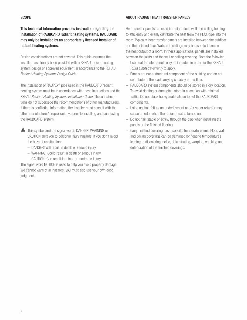
SCOPE
This technical information provides instruction regarding the installation of RAUBOARD radiant heating systems. RAUBOARD may only be installed by an appropriately licensed installer of radiant heating systems.
Design considerations are not covered. This guide assumes the installer has already been provided with a REHAU radiant heating system design or approved equivalent in accordance to the REHAU Radiant Heating Systems Design Guide.
The installation of RAUPEX® pipe used in the RAUBOARD radiant heating system must be in accordance with these instructions and the REHAU Radiant Heating Systems Installation Guide. These instruc-tions do not supersede the recommendations of other manufacturers. If there is conflicting information, the installer must consult with the other manufacturer’s representative prior to installing and connecting the RAUBOARD system.
This symbol and the signal words DANGER, WARNING or CAUTION alert you to personal injury hazards. If you don’t avoid the hazardous situation:– DANGER! Will result in death or serious injury– WARNING! Could result in death or serious injury– CAUTION! Can result in minor or moderate injury
The signal word NOTICE is used to help you avoid property damage. We cannot warn of all hazards; you must also use your own good judgment.
ABOUT RADIANT HEAT TRANSFER PANELS
Heat transfer panels are used in radiant floor, wall and ceiling heating to efficiently and evenly distribute the heat from the PEXa pipe into the room. Typically, heat transfer panels are installed between the subfloor and the finished floor. Walls and ceilings may be used to increase the heat output of a room. In these applications, panels are installed between the joists and the wall or ceiling covering. Note the following:− Use heat transfer panels only as intended in order for the REHAU
PEXa Limited Warranty to apply.− Panels are not a structural component of the building and do not
contribute to the load carrying capacity of the floor.− RAUBOARD system components should be stored in a dry location.
To avoid denting or damaging, store in a location with minimal traffic. Do not stack heavy materials on top of the RAUBOARD components.
− Using asphalt felt as an underlayment and/or vapor retarder may cause an odor when the radiant heat is turned on.
− Do not nail, staple or screw through the pipe when installing the panels or the finished flooring.
– Every finished covering has a specific temperature limit. Floor, wall and ceiling coverings can be damaged by heating temperatures leading to discoloring, noise, delaminating, warping, cracking and deterioration of the finished coverings.
3
System ComponentsThe RAUBOARD system comprises:− double groove panel− single groove panel− return groove panel− 10.1 mm RAUPEX O
2 barrier SDR11 PEXa pipe
− brass manifold connectors− polymer support bends (optional)− protection sleeves (optional)− SDR11 compression-sleeve fittings/sleeves and tool
(if required to repair pipe)
Installer Will Also Need:− silicon (not provided by REHAU)− fasteners (not provided by REHAU)– radiant heating system design including manifold circuit chart– sliding miter saw 10 in (255 mm) or equivalent
(must be capable of cross-cutting 2 x 12 lumber)– cordless drill with screwdriver bit and 1 in (25 mm) drill bit– chalk line, pencil, framing square, tape measure– caulking gun– vacuum– extension cord– PEX pipe cutter– chisel, hammer and rubber mallet– safety glasses (recommended)– work gloves (recommended)– hearing protection (recommended)– uncoiler (optional)– router with 7/16 in (12 mm) bit (optional)
Technical DetailsPanel Specifications Materials double/single groove panels plywood with aluminumreturn bend panels plywood Additional Specifications – panel height nominal 1/2 in (12.5 mm) thickness– plywood panels have low formaldehyde emission levels; they meet
or are exempt from most formaldehyde emission standards and regulations
Installation OverviewThe following sequence is the most efficient way to install the RAUBOARD radiant heating system.1. Gather documents2. Prepare jobsite3. Install manifold4. Insulate walls/ceilings, if required5. Position, align and secure RAUBOARD6. Install pipe with silicon7. Install underlayment, if required for finished floor covering8. Pressure test9. Insulate below subfloor10. Install finished covering
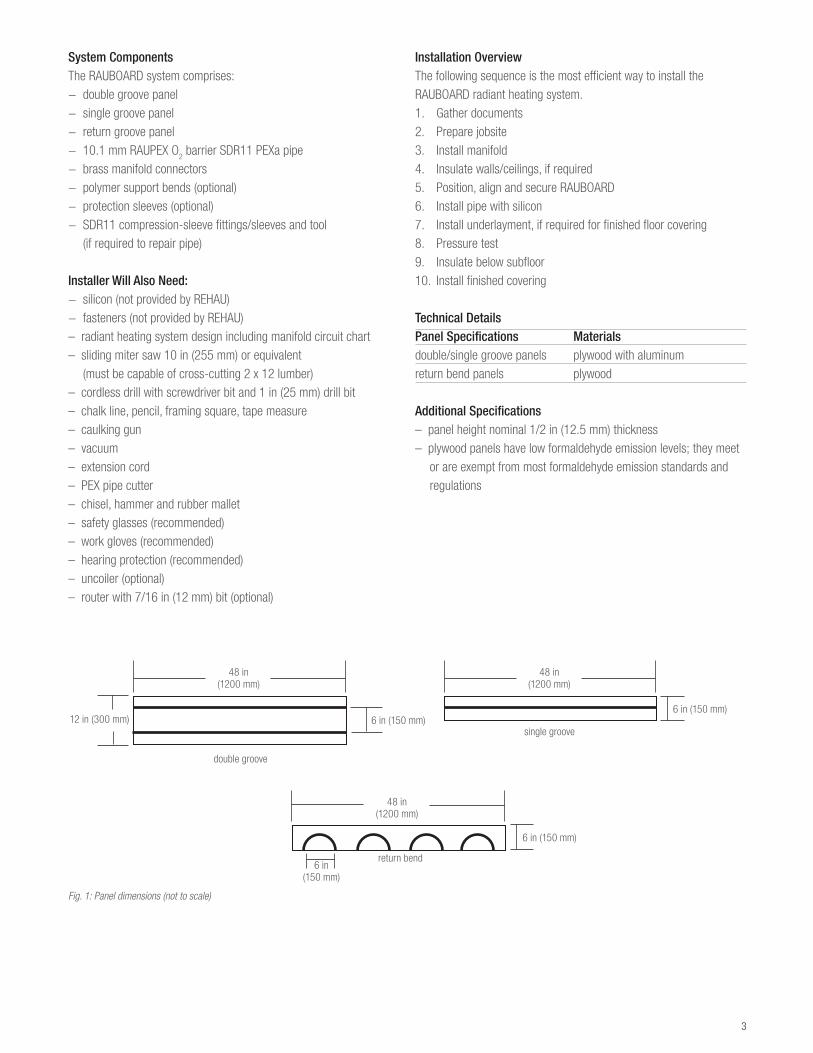
Fig. 1: Panel dimensions (not to scale)
12 in (300 mm) 6 in (150 mm)
48 in(1200 mm)
6 in (150 mm)
48 in(1200 mm)
double groove
single groove
6 in(150 mm)
return bend
6 in (150 mm)
48 in(1200 mm)
4
APPLYING RAUBOARD TO WOOD SUBFLOOR
This section applies to installing panels to both a plywood subfloor over suspended wood frame construction or a plywood subfloor over slab. See section APPLYING RAUBOARD TO SLAB for supplementary information, if applicable. An installation in a simple square room is described below. Skilled installers will adapt these instructions for complex room layouts.
1. Gather the necessary documents and specifications before beginning a radiant installation:− radiant heating system design including manifold circuit chart− building drawings− pertinent REHAU technical guidelines
2. Ensure site conditions are suitable for the installation of heat trans-fer panels (i.e., clear space to work and plywood or OSB subfloor that is flat, even, level, structurally sound, silent and free of debris). Correct any discrepancies before starting the installation. Follow all manufac-turer’s instructions for installing over plywood or OSB subflooring.
Confirm that the additional floor height due to the RAUBOARD has been taken into account. Door moldings, base plates, electrical outlets, etc. may need to be raised. Doors and thresholds may need to be modified.
Verify that the pipe layout and the panel orientation are properly designed based on the as-built site conditions. If necessary, revise the design before starting the installation.
Check that the planned circuit lengths are not too long. RAUPEX 10.1 mm pipe circuits should not exceed 250 ft (75 m) in length depending on flow and output requirements. Generally, REHAU recommends that these circuit lengths (including supply and return tails) be kept below 200 ft (60 m) to help minimize pump size and attain high system efficiencies.
Check that the orientation of the panels is the preferred orientation. The following factors may be important:− panel grooves should be installed perpendicular to hardwood
finished flooring to improve the ease of installation of the hardwood flooring and minimize chances of damaging the pipe.
− panel grooves should be installed in the direction of the longest room dimension to minimize the number of bends required, thus maximizing the pipe runs, and improving the ease of installation.
− panel grooves should be installed perpendicular to suspended floor joists when possible to add stiffness to the floor.
Check that the proposed finished floor coverings are per the design.
Note: System performance may not be attained if the insulation values of the floor coverings have not been taken into account.
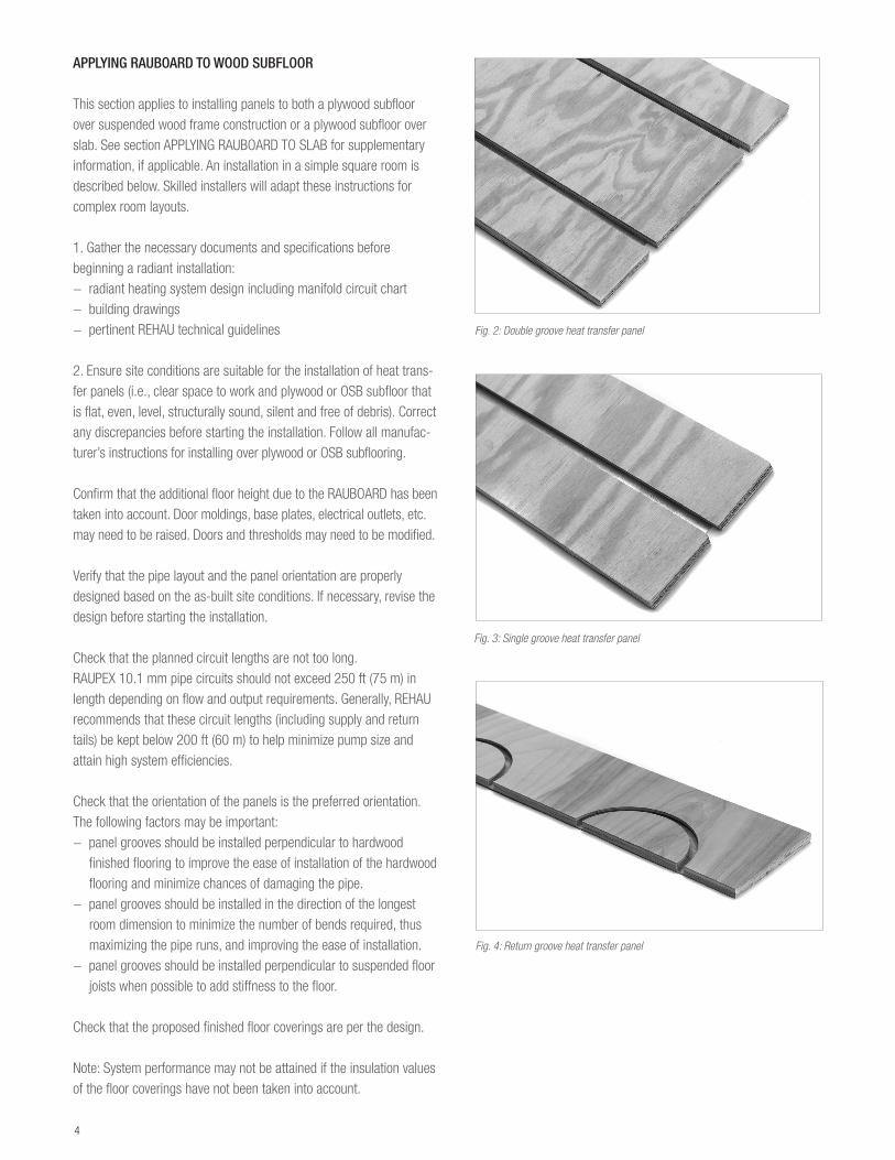
Fig. 2: Double groove heat transfer panel
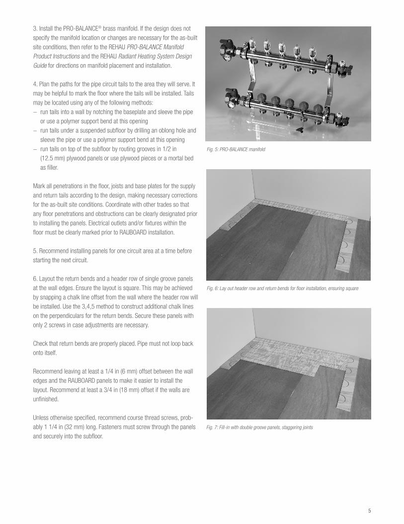
Fig. 3: Single groove heat transfer panel
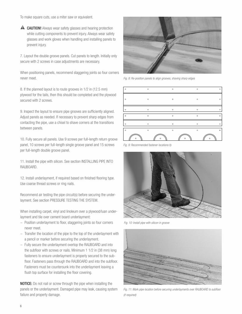
Fig. 4: Return groove heat transfer panel
5
3. Install the PRO-BALANCE® brass manifold. If the design does not specify the manifold location or changes are necessary for the as-built site conditions, then refer to the REHAU PRO-BALANCE Manifold Product Instructions and the REHAU Radiant Heating System Design Guide for directions on manifold placement and installation.
4. Plan the paths for the pipe circuit tails to the area they will serve. It may be helpful to mark the floor where the tails will be installed. Tails may be located using any of the following methods:− run tails into a wall by notching the baseplate and sleeve the pipe
or use a polymer support bend at this opening− run tails under a suspended subfloor by drilling an oblong hole and
sleeve the pipe or use a polymer support bend at this opening− run tails on top of the subfloor by routing grooves in 1/2 in
(12.5 mm) plywood panels or use plywood pieces or a mortal bed as filler.
Mark all penetrations in the floor, joists and base plates for the supply and return tails according to the design, making necessary corrections for the as-built site conditions. Coordinate with other trades so that any floor penetrations and obstructions can be clearly designated prior to installing the panels. Electrical outlets and/or fixtures within the floor must be clearly marked prior to RAUBOARD installation.
5. Recommend installing panels for one circuit area at a time before starting the next circuit.
6. Layout the return bends and a header row of single groove panels at the wall edges. Ensure the layout is square. This may be achieved by snapping a chalk line offset from the wall where the header row will be installed. Use the 3,4,5 method to construct additional chalk lines on the perpendiculars for the return bends. Secure these panels with only 2 screws in case adjustments are necessary.
Check that return bends are properly placed. Pipe must not loop back onto itself.
Recommend leaving at least a 1/4 in (6 mm) offset between the wall edges and the RAUBOARD panels to make it easier to install the layout. Recommend at least a 3/4 in (18 mm) offset if the walls are unfinished.
Unless otherwise specified, recommend course thread screws, prob-ably 1 1/4 in (32 mm) long. Fasteners must screw through the panels and securely into the subfloor.
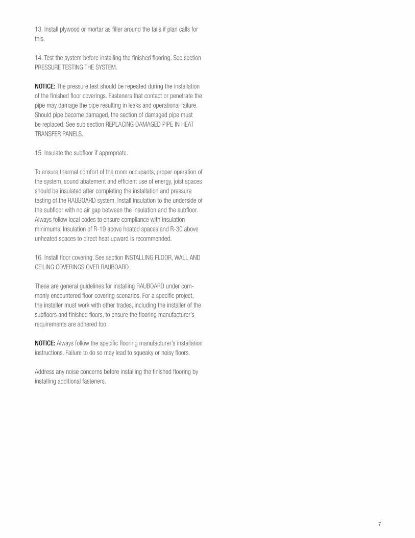
Fig. 5: PRO-BALANCE manifold
Fig. 6: Lay out header row and return bends for floor installation, ensuring square
Fig. 7: Fill-in with double groove panels, staggering joints
6
To make square cuts, use a miter saw or equivalent.
CAUTION! Always wear safety glasses and hearing protection while cutting components to prevent injury. Always wear safety glasses and work gloves when handling and installing panels to prevent injury.
7. Layout the double groove panels. Cut panels to length. Initially only secure with 2 screws in case adjustments are necessary.
When positioning panels, recommend staggering joints so four corners never meet.
8. If the planned layout is to route grooves in 1/2 in (12.5 mm) plywood for the tails, then this should be completed and the plywood secured with 2 screws.
9. Inspect the layout to ensure pipe grooves are sufficiently aligned. Adjust panels as needed. If necessary to prevent sharp edges from contacting the pipe, use a chisel to shave corners at the transitions between panels.
10. Fully secure all panels. Use 9 screws per full-length return groove panel, 10 screws per full-length single groove panel and 15 screws per full-length double groove panel.
11. Install the pipe with silicon. See section INSTALLING PIPE INTO RAUBOARD.
12. Install underlayment, if required based on finished flooring type. Use coarse thread screws or ring nails.
Recommend air testing the pipe circuit(s) before securing the under-layment. See section PRESSURE TESTING THE SYSTEM.
When installing carpet, vinyl and linoleum over a plywood/luan under-layment and tile over cement board underlayment:− Position underlayment to floor, staggering joints so four corners
never meet.− Transfer the location of the pipe to the top of the underlayment with
a pencil or marker before securing the underlayment.− Fully secure the underlayment overtop the RAUBOARD and into
the subfloor with screws or nails. Minimum 1 1/2 in (38 mm) long fasteners to ensure underlayment is properly secured to the sub-floor. Fasteners pass through the RAUBOARD and into the subfloor. Fasteners must be countersunk into the underlayment leaving a flush top surface for installing the floor covering.
NOTICE: Do not nail or screw through the pipe when installing the panels or the underlayment. Damaged pipe may leak, causing system failure and property damage.
Fig. 8: Re-position panels to align grooves, shaving sharp edges
Fig. 9: Recommended fastener locations ⊕
Fig. 10: Install pipe with silicon in groove
Fig. 11: Mark pipe location before securing underlayments over RAUBOARD to subfloor
(if required)
7
13. Install plywood or mortar as filler around the tails if plan calls for this.
14. Test the system before installing the finished flooring. See section PRESSURE TESTING THE SYSTEM.
NOTICE: The pressure test should be repeated during the installation of the finished floor coverings. Fasteners that contact or penetrate the pipe may damage the pipe resulting in leaks and operational failure. Should pipe become damaged, the section of damaged pipe must be replaced. See sub section REPLACING DAMAGED PIPE IN HEAT TRANSFER PANELS.
15. Insulate the subfloor if appropriate.
To ensure thermal comfort of the room occupants, proper operation of the system, sound abatement and efficient use of energy, joist spaces should be insulated after completing the installation and pressure testing of the RAUBOARD system. Install insulation to the underside of the subfloor with no air gap between the insulation and the subfloor. Always follow local codes to ensure compliance with insulation minimums. Insulation of R-19 above heated spaces and R-30 above unheated spaces to direct heat upward is recommended.
16. Install floor covering. See section INSTALLING FLOOR, WALL AND CEILING COVERINGS OVER RAUBOARD.
These are general guidelines for installing RAUBOARD under com-monly encountered floor covering scenarios. For a specific project, the installer must work with other trades, including the installer of the subfloors and finished floors, to ensure the flooring manufacturer’s requirements are adhered too.
NOTICE: Always follow the specific flooring manufacturer’s installation instructions. Failure to do so may lead to squeaky or noisy floors.
Address any noise concerns before installing the finished flooring by installing additional fasteners.
8
APPLYING RAUBOARD TO SLAB
This section applies to suspended, at- and below-grade concrete slabs. The addition of a plywood subfloor over the concrete is recom-mended, then install the RAUBOARD system in accordance to the section APPLYING RAUBOARD TO WOOD SUBFLOOR.
If the job site conditions allow the additional height, fastening RAUBOARD to a wood subfloor over top a slab is preferred to anchoring RAUBOARD directly into concrete. The insulating value of the wood subfloor between RAUBOARD and the slab increases the system efficiency by reducing the backlosses. And when securing the RAUBOARD or assembling a floating wood subfloor, screws/nails are less expensive and require less skill to install than anchors. Further, if a vapor barrier is required, the customer may desire a floating wood subfloor as there are no penetrations to the vapor barrier.
REHAU is providing general industry guidelines for installing a wood subfloor over concrete as an aid in communicating technical information to the engineer of record. The engineer of record shall be responsible for converting all necessary and available technical infor-mation into a construction specification that meets the functional and structural needs of the client, as well as complying with all applicable codes and local job site conditions.
Assembling Floating Wood Subfloor Over Slab1. Use a vapor barrier underneath the plywood subfloor for below-grade and on-grade applications. Follow flooring manufacturer’s recommendations regarding the requirements of a vapor barrier for above-grade applications. Recommend vapor barrier of 3 mil (mini-mum) PE film unless otherwise specified.
2. Recommend floating floor material of two layers 3/8 in (9.5 mm) minimum CD exposure 1 (CDX) plywood 4 x 8 sheets.
3. Place the first plywood layer without fastening, staggering joints between rows so four corners never meet. Leave 3/4 in (18 mm) gap between plywood at wall lines and vertical obstructions. Leave 1/8 in (3 mm) gap between sheets.
4. Place second plywood layer perpendicular or at 45° to the first layer, also staggering joints between rows so four corners never meet. Leave 3/4 in (18 mm) gap between plywood at wall lines and vertical obstructions. Leave 1/8 in (3 mm) gap between sheets.
5. Staple or staple and glue with construction adhesive the second layer to the first layer. Fasten 2 in (50 mm) from the edge and at 6 in (150 mm) spacing around the perimeter. Fasten at 12 in (300 mm) interior spacing. Be careful not to penetrate the vapor barrier below.
Nailing-Down Wood Subfloor Over Slab1. Use a vapor barrier underneath the plywood subfloor for below-grade and on-grade applications. Follow flooring manufacturer’s recommendations regarding the requirements of a vapor barrier for above-grade applications. Recommend vapor barrier of 3 mil (mini-mum) PE film unless otherwise specified.
2. Recommend subfloor material of one layer 5/8 in (15.5 mm) minimum CD exposure 1 (CDX) plywood 4 x 8 sheets.
3. Install the plywood layer, staggering joints between rows so four corners never meet. Leave 3/4 in (18 mm) gap between plywood at wall lines and vertical obstructions. Leave 1/8 in (3 mm) gap between sheets.
4. Fasten 2 in (50 mm) from the edge and at 6 in (150 mm) spacing around the perimeter. Fasten at 12 in (300 mm) interior spacing. Use anchors suitable for concrete application. Anchors to be installed ac-cording to manufacturer’s instructions and recommendations such as specifying length, drill size and/or shot load.
9
APPLYING RAUBOARD TO WALL OR CEILING WOOD JOISTS
This section applies to wood wall studs and wood ceiling joists. A simple rectangular wall installation is described below. Skilled install-ers will adapt these instructions for complex wall and ceiling layouts.
1. Gather the necessary documents and specifications before begin-ning a radiant installation:− radiant heating system design including manifold circuit chart− building drawings− pertinent REHAU technical guidelines
2. Ensure site conditions are suitable for the installation of RAUBOARD panels (i.e., clear space to work and studs and/or joists that are straight, evenly spaced, structurally sound, silent and free of debris). Correct any discrepancies before starting the installation. Install additional studs and blocking if necessary to ensure adequate nailing surfaces for the heat transfer panels.
Verify that the pipe layout and the panel orientation are properly designed based on the as-built site conditions. The pipe should be installed perpendicular to the studs and joists. If necessary, revise the design before starting the installation.
Check that the planned circuit lengths are not too long. RAUPEX 10.1 mm O
2 Barrier pipe circuits should not exceed 250 ft (75 m) in
length depending on flow and output requirements. Generally, REHAU recommends that these circuit lengths (including supply and return tails) be kept below 200 ft (60 m) to help minimize pump size and attain high system efficiencies.
3. Insulate the wall/ceiling if appropriate before installing RAUBOARD. Install with no air gap between the insulation and the backside of the RAUBOARD. Always follow local codes to ensure compliance with insulation minimums.
4. Install the PRO-BALANCE brass manifold. If the design does not specify the manifold location or changes are necessary for the as-built site conditions, then refer to the REHAU PRO-BALANCE Manifold Product Instructions and the REHAU Radiant Heating Systems Design Guide for directions on manifold placement and installation.
5. Plan the paths for the circuit tails to the area they will serve. It may be helpful to mark the path where the tails will be installed. Tails may be located using any of the following methods:− run tails through walls sleeving pipe at joist penetrations− run tails through base plate and under suspended subfloor, sleeving
pipe at floor penetrations− integrate tails into a floor circuit by transitioning through the base
plate and sleeve the pipe or use a polymer support bend at the transition
Mark all penetrations in the wall, ceiling and floor for the supply and return tails according to the design, making necessary corrections for the as-built site conditions. Coordinate with other trades so that any floor penetrations and obstructions can be clearly designated prior to installing the panels. Electrical outlets and/or fixtures within the wall must be clearly marked prior to RAUBOARD installation.
6. Recommend installing panels for one circuit area at a time before starting the next circuit.
10
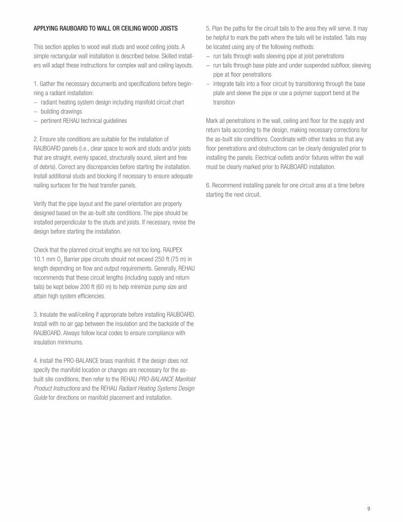
7. Install a first header row of single or double groove panels with 2 screws starting near the floor and ensuring the layout is level. This may be achieved by snapping a level chalk line. Continue to install grooved panels to the design height. Cut components to length as required.
Unless otherwise specified, recommend course thread screws, prob-ably 2 in. (50 mm) long. Fasteners must screw through the panels and securely into the stud and/or joist.
CAUTION! Always wear safety glasses and hearing protection while cutting components to prevent injury. Always wear safety glasses and work gloves when handling and installing panels to prevent injury.
8. Install the return bends at the ends of the layout.
Check return bends are properly placed. Pipe must not loop back onto itself.
9. Inspect the layout to ensure pipe grooves are sufficiently aligned. Adjust panels as needed. If necessary to prevent sharp edges from contacting the pipe, use a chisel to shave plywood corners at the transitions between return bend and aluminum panels.
10. Fully secure all components at each stud or joist.
11. Install the pipe with silicon. See section INSTALLING PIPE INTO RAUBOARD.
12. Install stud guard steel protectors over pipes where they cross studs and joists.
13. Install nailing strips of 1/2 in (12.5 mm) plywood to studs and joists as required to create a level surface to install the wall or ceiling covering.
14. Test the system before installing the finished coverings. See section PRESSURE TESTING THE SYSTEM.
NOTICE: The pressure test should be repeated during the installation of the finish floor coverings. Fasteners that contact or penetrate the pipe may damage the pipe resulting in leaks and operational failure. Should pipe become damaged, the section of damaged pipe must be replaced. See sub section REPLACING DAMAGED PIPE IN HEAT TRANSFER PANELS.
15. Install wall and ceiling coverings. See section INSTALLING FLOOR, WALL AND CEILING COVERINGS OVER RAUBOARD.
Fig. 12: Install header row for wall installation
Fig. 13: Typical wall installation with tails routing to manifold below floor
11
INSTALLING PIPE INTO RAUBOARD
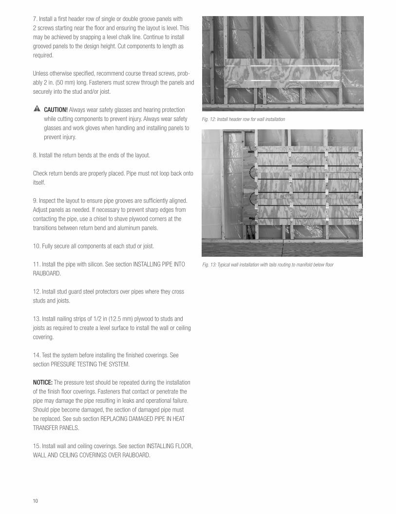
1. If required by the circuit layout, drill penetrations for supply and return tails. Subfloor penetrations should be wide enough, a mini-mum of 1 in (25 mm), to accommodate the pipe and support bend or protection sleeving and long enough, a minimum of 3 in (75 mm), to allow a smooth bend in the pipe. Joist penetrations should be large enough to accommodate the pipe and isolating clamp, protection sleeve or bushing.
2. Before installing the pipe, make sure the panel surface and the grooves are free of debris and obstructions by vacuuming.
3. Recommend starting with the pipe on the uncoiler in the room where the circuit is being installed. From this circuit area, route the supply tail of pipe through the floor, joist and wall penetrations to the manifold. Protect pipe at floor and joist penetrations with isolating clamps, protection sleeving, bushings or support bends. Secure pipe under the subfloor with clamps or clips if applicable. Connect supply tail to the correct manifold supply outlet according to the radiant heating design. Refer to the REHAU PRO-BALANCE Manifold Product Instructions for properly connecting pipe to the manifold.
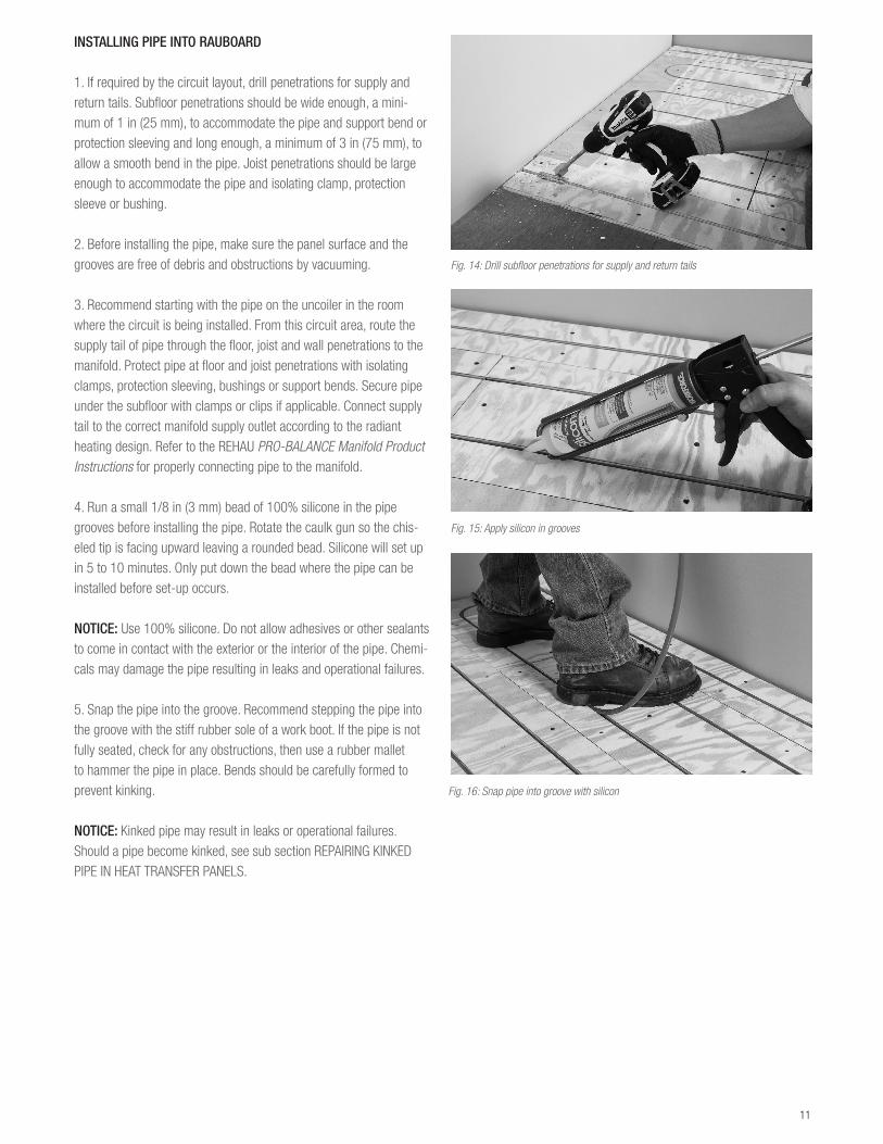
4. Run a small 1/8 in (3 mm) bead of 100% silicone in the pipe grooves before installing the pipe. Rotate the caulk gun so the chis-eled tip is facing upward leaving a rounded bead. Silicone will set up in 5 to 10 minutes. Only put down the bead where the pipe can be installed before set-up occurs.
NOTICE: Use 100% silicone. Do not allow adhesives or other sealants to come in contact with the exterior or the interior of the pipe. Chemi-cals may damage the pipe resulting in leaks and operational failures.
5. Snap the pipe into the groove. Recommend stepping the pipe into the groove with the stiff rubber sole of a work boot. If the pipe is not fully seated, check for any obstructions, then use a rubber mallet to hammer the pipe in place. Bends should be carefully formed to prevent kinking.
NOTICE: Kinked pipe may result in leaks or operational failures. Should a pipe become kinked, see sub section REPAIRING KINKED PIPE IN HEAT TRANSFER PANELS.
Fig. 14: Drill subfloor penetrations for supply and return tails
Fig. 15: Apply silicon in grooves
Fig. 16: Snap pipe into groove with silicon
12
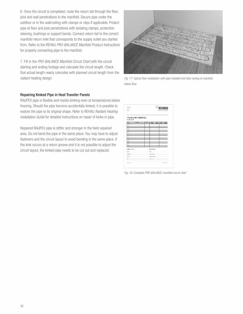
6. Once the circuit is completed, route the return tail through the floor, joist and wall penetrations to the manifold. Secure pipe under the subfloor or in the wall/ceiling with clamps or clips if applicable. Protect pipe at floor and joist penetrations with isolating clamps, protection sleeving, bushings or support bends. Connect return tail to the correct manifold return inlet that corresponds to the supply outlet you started from. Refer to the REHAU PRO-BALANCE Manifold Product Instructions for properly connecting pipe to the manifold.
7. Fill in the PRO-BALANCE Manifold Circuit Chart with the circuit starting and ending footage and calculate the circuit length. Check that actual length nearly coincides with planned circuit length from the radiant heating design.
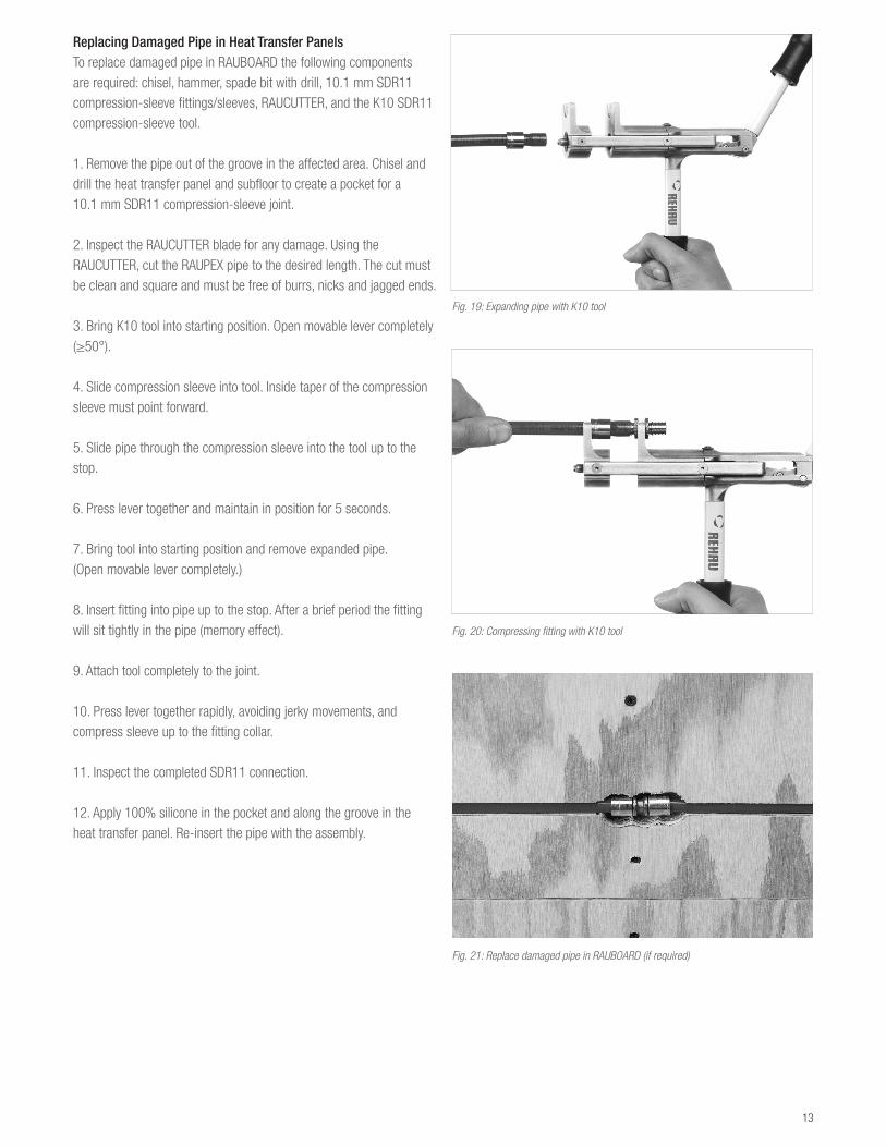
Repairing Kinked Pipe in Heat Transfer PanelsRAUPEX pipe is flexible and resists kinking even at temperatures below freezing. Should the pipe become accidentally kinked, it is possible to restore the pipe to its original shape. Refer to REHAU Radiant Heating Installation Guide for detailed instructions on repair of kinks in pipe.
Repaired RAUPEX pipe is stiffer and stronger in the field-repaired area. Do not bend the pipe in the same place. You may have to adjust fasteners and the circuit layout to avoid bending in the same place. If the kink occurs at a return groove and it is not possible to adjust the circuit layout, the kinked pipe needs to be cut out and replaced.
Fig. 18: Complete PRO-BALANCE manifold circuit chart
Fig. 17: Typical floor installation with pipe installed and tails routing to manifold
below floor
13
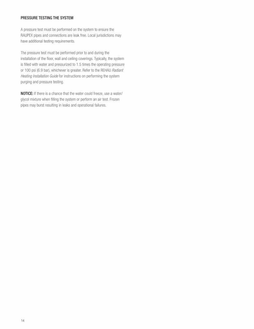
Replacing Damaged Pipe in Heat Transfer PanelsTo replace damaged pipe in RAUBOARD the following components are required: chisel, hammer, spade bit with drill, 10.1 mm SDR11 compression-sleeve fittings/sleeves, RAUCUTTER, and the K10 SDR11 compression-sleeve tool.
1. Remove the pipe out of the groove in the affected area. Chisel and drill the heat transfer panel and subfloor to create a pocket for a 10.1 mm SDR11 compression-sleeve joint.
2. Inspect the RAUCUTTER blade for any damage. Using the RAUCUTTER, cut the RAUPEX pipe to the desired length. The cut must be clean and square and must be free of burrs, nicks and jagged ends.
3. Bring K10 tool into starting position. Open movable lever completely (≥50°).
4. Slide compression sleeve into tool. Inside taper of the compression sleeve must point forward.
5. Slide pipe through the compression sleeve into the tool up to the stop.
6. Press lever together and maintain in position for 5 seconds.
7. Bring tool into starting position and remove expanded pipe. (Open movable lever completely.)
8. Insert fitting into pipe up to the stop. After a brief period the fitting will sit tightly in the pipe (memory effect).
9. Attach tool completely to the joint.
10. Press lever together rapidly, avoiding jerky movements, and compress sleeve up to the fitting collar.
11. Inspect the completed SDR11 connection.
12. Apply 100% silicone in the pocket and along the groove in the heat transfer panel. Re-insert the pipe with the assembly.
Fig. 19: Expanding pipe with K10 tool
Fig. 20: Compressing fitting with K10 tool
Fig. 21: Replace damaged pipe in RAUBOARD (if required)
14
PRESSURE TESTING THE SYSTEM
A pressure test must be performed on the system to ensure the RAUPEX pipes and connections are leak free. Local jurisdictions may have additional testing requirements.
The pressure test must be performed prior to and during the installation of the floor, wall and ceiling coverings. Typically, the system is filled with water and pressurized to 1.5 times the operating pressure or 100 psi (6.9 bar), whichever is greater. Refer to the REHAU Radiant Heating Installation Guide for instructions on performing the system purging and pressure testing.
NOTICE: If there is a chance that the water could freeze, use a water/glycol mixture when filling the system or perform an air test. Frozen pipes may burst resulting in leaks and operational failures.
15
INSTALLING FLOOR, WALL AND CEILING COVERINGS
REHAU is providing general industry practices for installing finished coverings over RAUBOARD. Finished floor, wall and ceiling coverings must be installed according to the manufacturer’s instruc-tions, recommendations and best practice.
NOTICE: Do not nail, staple or screw into the pipe. Fasteners that contact or penetrate the pipe may damage the pipe resulting in leaks and operational failure.
Every finished covering has a specific temperature limit. Verify products are approved for use with radi-ant heating systems. Confirm the finished coverings has been taken into account. If necessary, check temperatures are within limitations set by the man-ufacturer of the finished covering and associated underlayment, adhesives, compounds and grouts. Refer to the REHAU Radiant Heating Systems Design Guide for additional design assistance.
NOTICE: Floor, wall and ceiling coverings can be damaged by heating temperatures leading to dis-coloring, noise, delaminating, warping, cracking and deterioration of the finished coverings.
If using adhesives, apply adhesives directly to the RAUBOARD avoiding the pipe.
NOTICE: Do not allow adhesives to come in contact with the exterior or the interior of the RAUPEX pipe. Chemicals may damage the pipe resulting in leaks and operational failures.
Generic, common, typical thinset mix with water are acceptable in contact with the pipe as these are comparable to the materials used in concrete and overpour construction methods. If using a modified thinset, additives need to be checked with REHAU’s engineering department to maintain the application-specific warranty.
NOTICE: Check compatibility before allowing chemi-cals to come in contact with the exterior or interior of the pipe. Chemicals may damage the pipe result-ing in leaks and operational failures.
Gypsum Wall and Ceiling BoardTypical installation is to screw or nail gypsum board over the RAUBOARD. Secure gypsum board through the RAUBOARD and into the studs, joists or blocking behind the panels. Recommend minimum 2 in (50 mm) long fasteners to ensure gypsum board is properly secured. Then join gypsum boards with joint tape and joint compound.
Tile Over Cement Board UnderlaymentTypical installation is to apply cement boards over the RAUBOARD, then apply tile. Secure underlayment through the RAUBOARD into the subfloor or slab, fill the seams in the ce-ment board, apply a layer of thinset, install tile and grout.
If using a leveling bed, recommend applying to the subfloor/slab and then install the RAUBOARD overtop followed by the cement board, thinset then tile.
Tile Over Isolation Mat UnderlaymentTypical installation is to apply mat over the RAUBOARD, then apply tile. Apply thinset to RAUBOARD, apply and properly seat isolation mat, apply another layer of thinset, install tile and grout.
Tile Over Mud BedTypical installation is to apply mud bed over the RAUBOARD, then apply tile. Install suit-able moisture barrier to RAUBOARD. Fasten wire lathe over barrier. Pour mortar onto wire lathe. Pack and level to appropriate height and minimum thickness. Apply a layer of thinset, install tile and grout.
Broadloom Carpet and Padding, Carpet Tiles, Vinyl or Linoleum Over a Plywood UnderlaymentTypical installation is to apply underlayment over the RAUBOARD, then carpet with or without pad.
For broadloom carpet, install tackless strip around the wall edges, staple pad to underlay-ment and join seams, place carpet, seal carpet seams, stretch and secure carpet to tack-less strip. Ensure staples holding the pad are short enough they do not contact the pipe.
For carpet tiles, vinyl and linoleum adhesively apply tiles to underlayment.
Solid Strip or Plank Hardwood FlooringTypical installation is to apply hardwood flooring over the RAUBOARD. Ensure acceptable jobsite conditions, follow acclimation guidelines for installing hardwood flooring, follow hardwood installation instructions for the appropriate grade level (below, at or above grade) and ensure vapor barrier is correctly installed (if applicable). Nail, staple or cleat hardwood through RAUBOARD and into the subfloor. Fasten every 8 in (200 mm) along the edge of the strip/plank. Minimum 2 in (50 mm) long fasteners to ensure hardwood is properly secured to the subfloor.
Engineered or Laminate Wood FlooringThe rapid development of engineered or laminate wood floor precludes the description of a typical installation. Follow all manufacturer’s guidelines. If adhesively securing this wood flooring, first apply adhesive directly to the RAUBOARD avoiding the pipe, then place the desired underlayment and flooring.

www.rehau.com [email protected]
For updates to this publication, visit na.rehau.com/resourcecenter The information contained herein is believed to be reliable, but no representations, guarantees or warranties of any kind are made as to its accuracy, suitability for particular applications or the results to be obtained therefrom. Before using, the user will determine suitability of the information for user’s intended use and shall assume all risk and liability in connection therewith. © 2017 REHAU
855.670 en 01.2017