Embed Size (px)
Citation preview

RARE EARTH ELEMENT INDETIFICATION FROM ELECTRONIC WASTE: SOLID PHASE
SEPARATION (ACID LEACHING)
NUR ASHIKIN BINTI JAMIN
Thesis submitted in partial fulfilment of the requirements for the award of the degree of
Bachelor of Chemical Engineering
Faculty of Chemical & Natural Resources Engineering UNIVERSITI MALAYSIA PAHANG
JANUARY 2015
©NUR ASHIKIN BINTI JAMIN (2015)
III

ABSTRACT
Rare earth element (REE) commonly used as a significant component in electronic
appliance such as Liquid-crystal display (LCD). Nowadays, rare earth element is being
disposed rather than being recycled or reused. Due to the increased in demand, rare
earth element become more economically profitable. Recycling or recovery of rare earth
element from electronic waste will help to secure the effect on price, supply and
quantity of the element. The aim of this research is to identify the rare earth element
contain in the LCD. The separation process of solid phase extraction (SPE) or so called
as leaching method were introduced to identify the rare earth in the LCD. The
concentration of acid solution parameter was varied to examine the optimum condition
for leaching process of LCD by chromatography analysis using X-ray Diffraction
(XRD).
VIII

ABSTRAK
Unsur nadir bumi (REE) biasanya digunakan sebagai salah satu komponen penting
dalam perkakas elektronik seperti paparan cecair kristal (LCD). Pada masa kini, unsur
nadir bumi kebanyakkaimya dilupuskan dan tidak dikitar semula atau digunakan
semula. Disebabkan oleh peningkatan dalam permintaan, unsur nadir bumi menjadi
lebih menguntungkan dan segi ekonomi. Kitar semula atau pemulihan unsur nadir bumi
dari sisa elektronik akan membantu untuk mengurangkan kesan ke atas harga, bekalan
dan kuantiti unsur. Tujuan kajian mi adalah untuk mengenal pasti elemen nadir bumi
terkandung di dalam LCD. Proses pemisahan pengekstrakan fasa pepejal (SPE) atau
dipanggil sebagai kaedah larut lesap telah diperkenalkan untuk mengenalpasti nadir
bumi di dalam LCD. Kepekatan asid sebagai parameter telah diubah untuk memeriksa
keadaan optimum untuk proses larut lesap LCD dengan analisis kromatografi
menggunakan X-ray Zarina (XRD).
IX
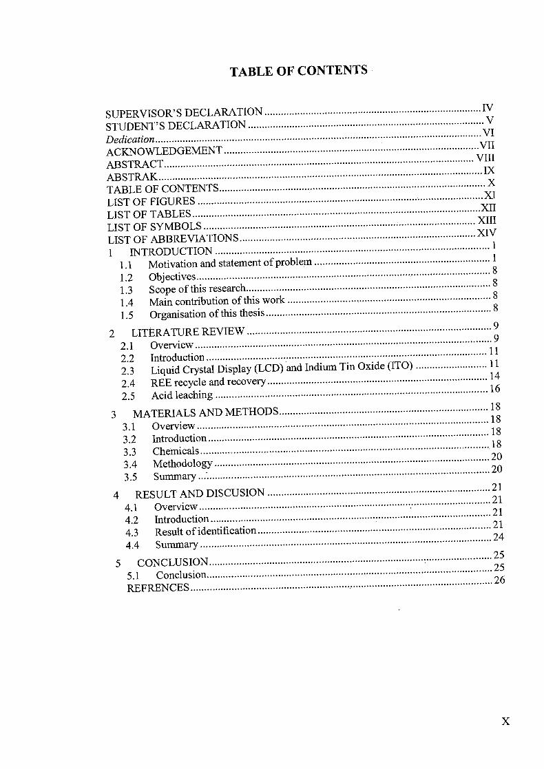
TABLE OF CONTENTS
DECLARATION SUPERVISOR'S ............................................................................... IV
DECLARATION V STUDENT'S .......................................................................................Dedication......................................................................................................................VI
VII ACKNOWLEDGEMENT............................................................................................. ABSTRACT................................................................................................................. VIII
ABSTRAK...................................................................................................................... IX X TABLEOF CONTENTS .................................................................................................
LISTOF FIGURES .........................................................................................................
.XI
LISTOF TABLES .........................................................................................................XII
LISTOF SYMBOLS ...................................................................................................XIII LIST OF ABBREVIATIONS ...................................................................................... XIV
1 INTRODUCTION .................................................................................................... 1
1.1 Motivation and statement of problem................................................................ 1
1.2 Objectives ........................................................................................................... 8 8
1.3 Scope of this research.........................................................................................
1.4 Main contribution of this work .......................................................................... 8
1.5 Organisation of this thesis.................................................................................. 8
2 LITERATURE REVIEW .......... . .............................................................................. 9
2.1 Overview............................................................................................................ 11
2.2 Introduction ......................................................................................................
2.3 Liquid Crystal Display (LCD) and Indium Tin Oxide (ITO) ..........................11
2.4 REE recycle and recovery................................................................................ 14
2.5 Acid leaching ................................................................................................... 16
3 MATERIALS AND METHODS............................................................................ 18
3.1 Overview.......................................................................................................... 18 18
3.2 Introduction......................................................................................................18
3.3 Chemicals...........................................................................................................20
3.4 Methodology ....................................................................................................20
3.5 Summary ...........................................................................................................
4 RESULT AND DISCUSION ................................................................................. 21
4.1 Overview........................................................................................................... 21 21
4.2 Introduction......................................................................................................21
4.3 Result of identification.....................................................................................24
4.4 Summary..........................................................................................................
5 CONCLUSION ........................................................................................................ 25 25
5.1 Conclusion ............................................... ......................................................... 26 REFRENCES...............................................................................................................
X
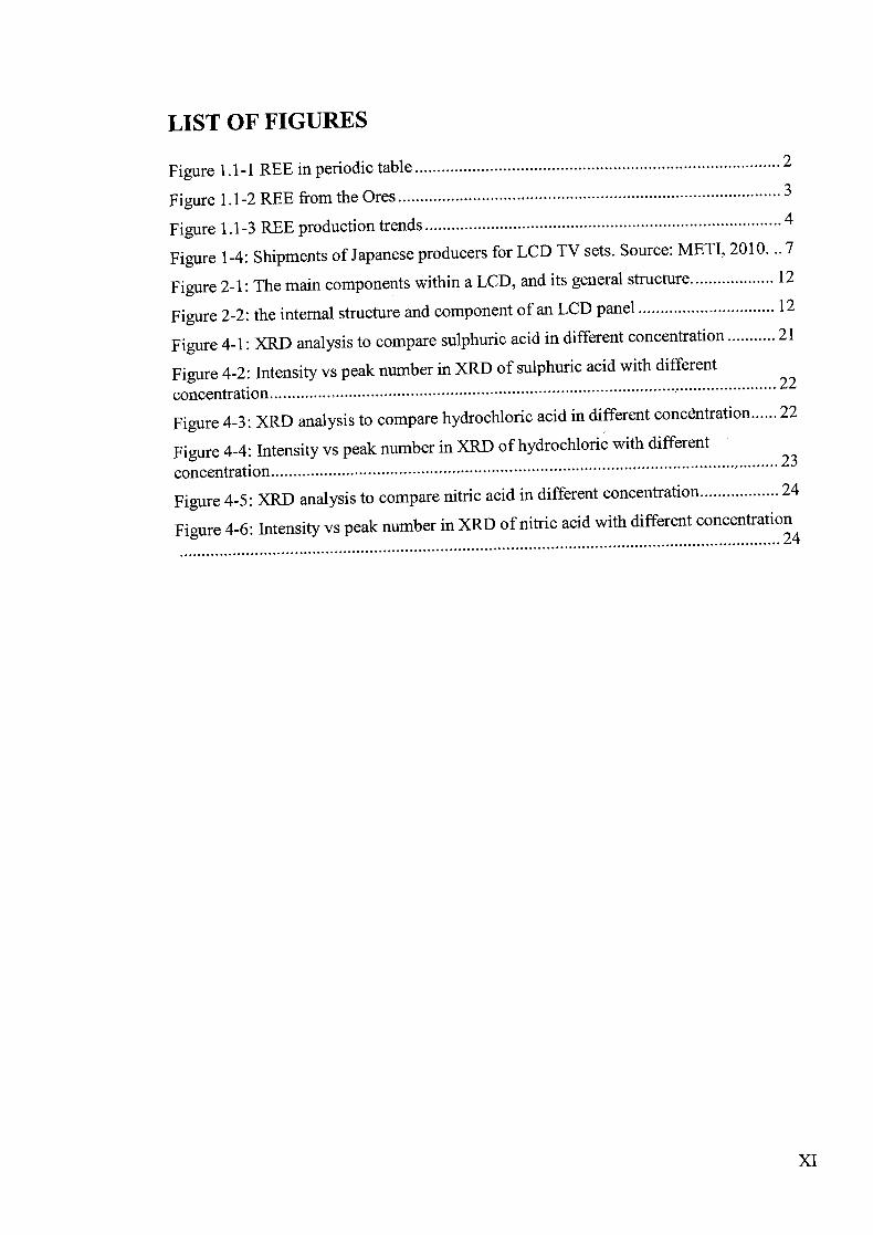
LIST OF FIGURES
Figure 1.1-1 REE in periodic table................................................................................... 2
Figure1.1-2 REE from the Ores....................................................................................... 3
Figure 1.1-3 REE production trends................................................................................. 4
Figure 1-4: Shipments of Japanese producers for LCD TV sets. Source: METI, 2010-7 7
Figure 2-1: The main components within a LCD, and its general structure................... 12
Figure 2-2: the internal structure and component of an LCD panel............................... 12
Figure 4-1: XRD analysis to compare sulphuric acid in different concentration........... 21
Figure 4-2: Intensity vs peak number in XRD of sulphuric acid with different
concentration .................................................................................................................... 22
Figure 4-3: XRD analysis to compare hydrochloric acid in different concentration ...... 22
Figure 4-4: Intensity vs peak number in XRD of hydrochloric with different
concentration ......................................................................................................... .......... 23
Figure 4-5: XRD analysis to compare nitric acid in different concentration.................. 24
Figure 4-6: Intensity t vs peak number in XRD of nitric acid with different concentration ......................................................24
XI
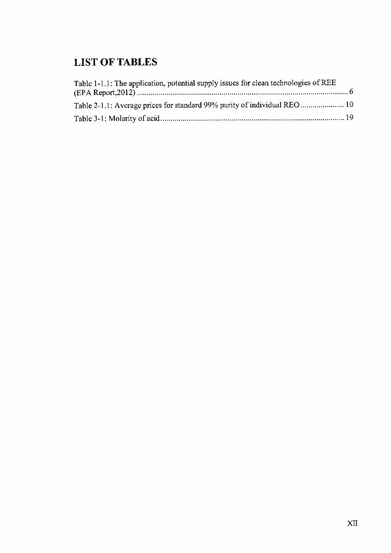
LIST OF TABLES
Table 1-1.1: The application, potential supply issues for clean technologies of REE (EPA Report,2012) ...........................................................................................................6
Table 2-1. 1: Average prices for standard 99% purity of individual REO......................10
Table3-1: Molarity of acid.............................................................................................19
XII
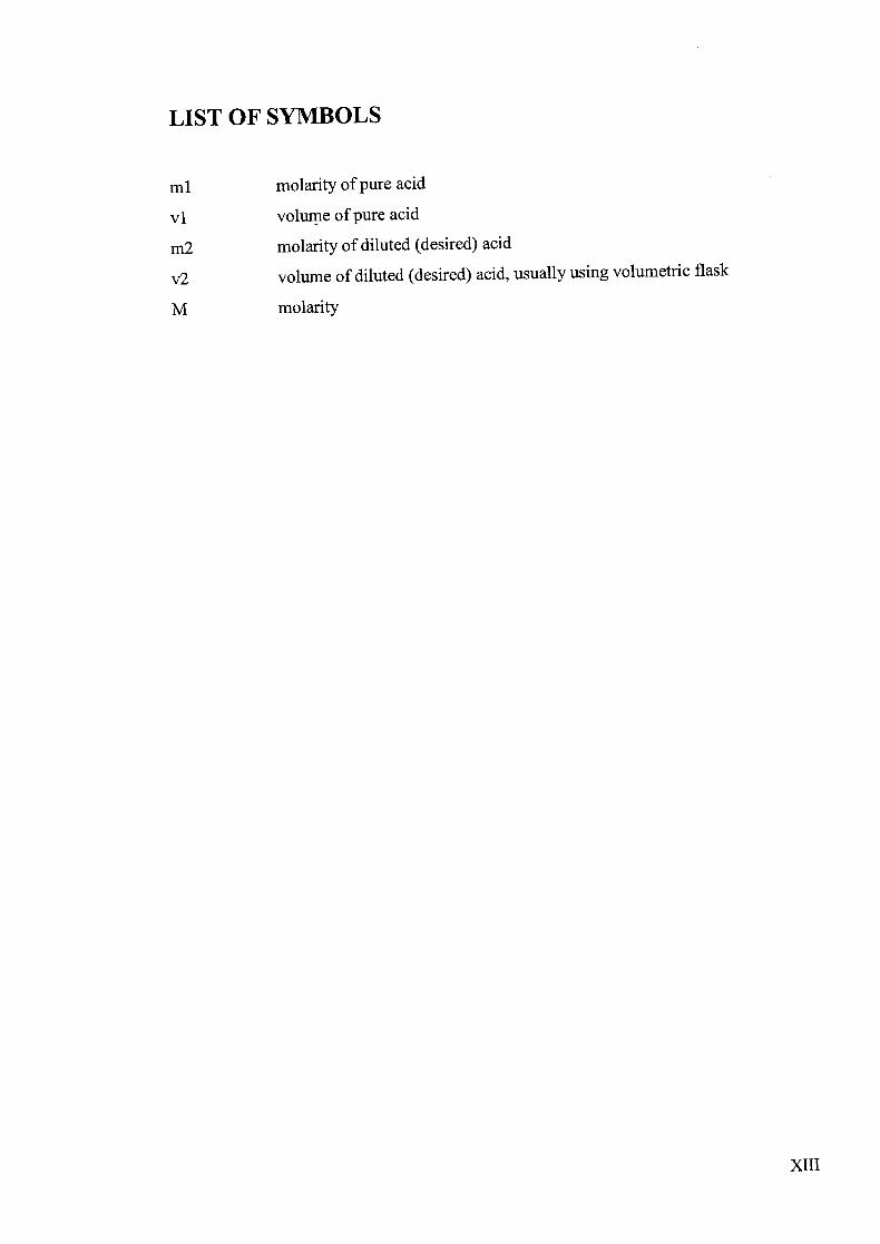
LIST OF SYMBOLS
ml molarity of pure acid
vi volume of pure acid
m2 molarity of diluted (desired) acid
Q volume of diluted (desired) acid, usually using volumetric flask
M molarity
XIII
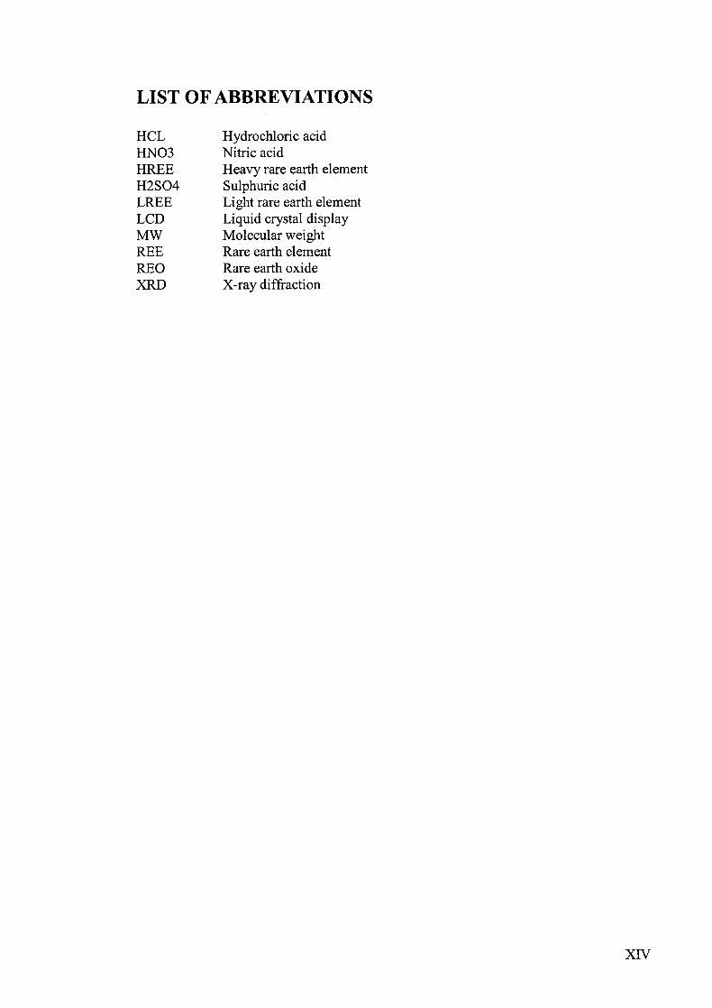
LIST OF ABBREVIATIONS
HCL Hydrochloric acid HINO3 Nitric acid HREE Heavy rare earth element H2SO4 Sulphuric acid LREE Light rare earth element LCD Liquid crystal display MW Molecular weight REE Rare earth element REO Rare earth oxide XRD X-ray diffraction
XIV
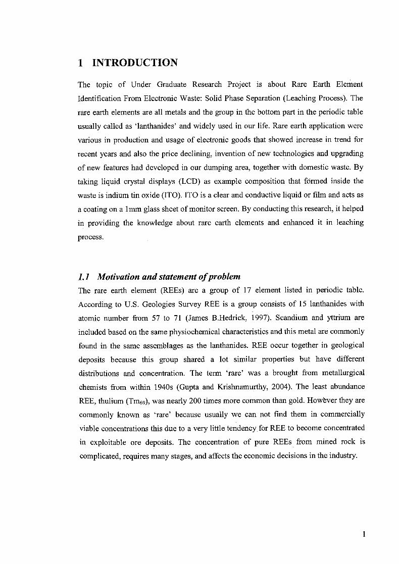
1 INTRODUCTION
The topic of Under Graduate Research Project is about Rare Earth Element
Identification From Electronic Waste: Solid Phase Separation (Leaching Process). The
rare earth elements are all metals and the group in the bottom part in the periodic table
usually called as 'lanthanides' and widely used in our life. Rare earth application were
various in production and usage of electronic goods that showed increase in trend for
recent years and also the price declining, invention of new technologies and upgrading
of new features had developed in our dumping area, together with domestic waste. By
taking liquid crystal displays (LCD) as example composition that formed inside the
waste is indium tin oxide (ITO). ITO is a clear and conductive liquid or film and acts as
a coating on a inmi glass sheet of monitor screen. By conducting this research, it helped
in providing the knowledge about rare earth elements and enhanced it in leaching
process.
1.1 Motivation and statement ofproblem The rare earth element (REEs) are a group of 17 element listed in periodic table.
According to U.S. Geologies Survey REE is a group consists of 15 lanthanides with
atomic number from 57 to 71 (James B.Hedrick, 1997). Scandium and yttrium are
included based on the same physiochemical characteristics and this metal are commonly
found in the same assemblages as the lanthanides. REE occur together in geological
deposits because this group shared a lot similar properties but have different
distributions and concentration. The term 'rare' was a brought from metallurgical
chemists from within 1940s (Gupta and Krishnamurthy, 2004). The least abundance
REE, thulium (Tm69), was nearly 200 times more common than gold. However they are
commonly known as 'rare' because usually we can not find them in commercially
viable concentrations this due to a very little tendency for REE to become concentrated
in exploitable ore deposits. The concentration of pure REEs from mined rock is
complicated, requires many stages, and affects the economic decisions in the industry.
1

He
Be BCNOFNe Li 10811 12811 74097 50399 18458 90109
111213 14 Is
AIpsaAr . Is
- 25 28 09571 31895 35133 99915
- 515 095353 09' 89 991 p5353 47931
21 248799
25 2f 27 28 29 30 31 32 33 34
19 20 21 22 Co Ni OjZnGaGeAsSe Br Kr sm oxa - -- 19:. -
3'0 43 42 45 490 41 48 49 50 21 22 03 5'
37
RbSr 32 '9
Y40 41 I
8953
Xe 7390
99453 315 999% 912 90Th 9335 (4 07127 93 0912 13737 1% 07 275 52350
8.999% 213557 3790
755819 5349 9fl371.
so 82 83 83 10 Be
_15
s Ea Hf Ta W Re Os r R Au. Hg 11 Pb BiPb At Rn 13281 13073 71821 10981 18383 70911 09212 10081 79730 13973 _!_ -2_ _EL . J!. .JEI_
09ti 0308107 500 91539 811I' 31133133
07 98 104 300 700 107 100 . 109 112 . 111
Fr Re RI D Sg Rh Hs Mt . Ds Rg 0731] __ __ __ 50] 0705 ]09] r-11 0705
-
La Ge . ?dF1P c LuIM, Val
Er39ar' p70938-9371 1357967 t40J9 p8237381 17574.8. 2*75 189Jfl 91332738 a-ant 741799 093191' 1189 093099%
AI1 °h Pa i - Cic Cf -- EsFrn32131 4300 MdNo l 21
Figure 1.1-1 REE in periodic table
REEs were divided into two classes which is light rare earth element (LREEs) and
heavy rare earth element (HREEs), categorized based on their electron configuration
Lanthanum through gadolinium with an atomic number from 57 to 64 categorized as
LREE while terbium through lutetium with an atomic number 65 to 71, and also yttrium
(atomic number 39) were included in HREE. Usually the HREEs are relatively less
common in nature but more valuable. Xenotime for example is one of the sources of
REE minerals but only a minor contributor to the production of REEs. Xenotime were
produced as the by-product from tin-mining in Malaysia. However, an important scale of the Chinese rare-earth production is sourced from ion absorption clays, which
themselves appear to have been derived from the deep weathering of source rocks
containing xenotime (Simon, W. 2010).
The overall process to obtain REE from ore was very complicated and costly. (Refer
Figure 1.2). At first, the ore (bastnaesite) containing minerals were taken out from the ground using usual mining procedures. The bastnaesite were then been removed by
crushing the ore into smaller size then it was placed into a grinding mill. The fine sand
or silt the different mineral grains from ore milling process then continue the bastnaesite
separation process from other nonessential minerals.
2
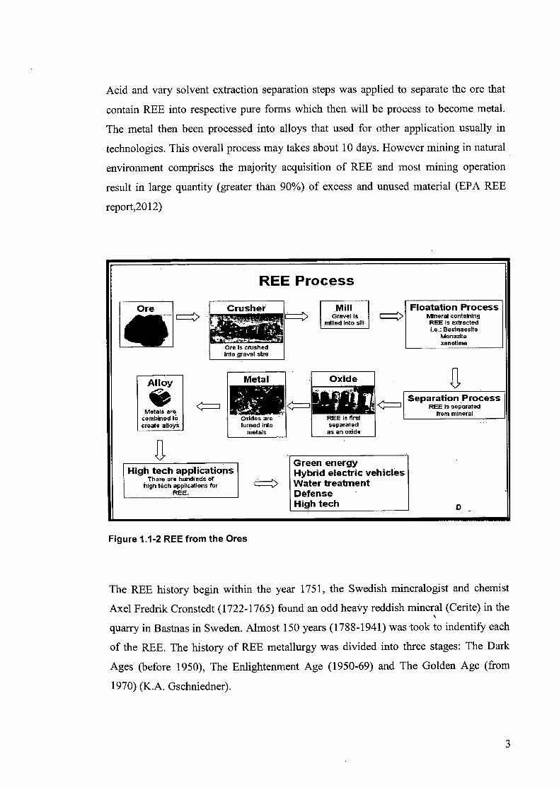
Acid and vary solvent extraction separation steps was applied to separate the ore that
contain REE into respective pure forms which then will be process to become metal.
The metal then been processed into alloys that used for other application usually in
technologies. This overall process may takes about 10 days. However mining in natural
environment comprises the majority acquisition of REE and most mining operation
result in large quantity (greater than 90%) of excess and unused material (EPA REE
report,20 12)
REE Process
Ore Crusher Mill - Floatation Process
miHed Into sill PEE is extracted I.e.; Bastnaeslte
Monazite
Ore Is crushedxenotime
into gravel se
Alloy T Metal I Oxide
REE Is separated Metals are
-: __________Separation Process
from mineral combined to Oxides are REF is flrst create alloys turned into separated
metals as an oxide
. ... Green energy High tech applications Hybrid electric vehicles
There are
hundreds of I high tech applications for Water treatment
REE. Defense High tech D -
Figure 1.1-2 REE from the Ores
The REE history begin within the year 1751, the Swedish mineralogist and chemist
Axel Fredrik Cronstedt (1722-1765) found an odd heavy reddish mineral (Cerite) in the
quarry in Bastnas in Sweden. Almost 150 years (1788-1941) was -took to indentify each
of the REE. The history of REE metallurgy was divided into three stages: The Dark
Ages (before 1950), The Enlightenment Age (1950-69) and The Golden Age (from
1970) (K.A. Gschniedner).
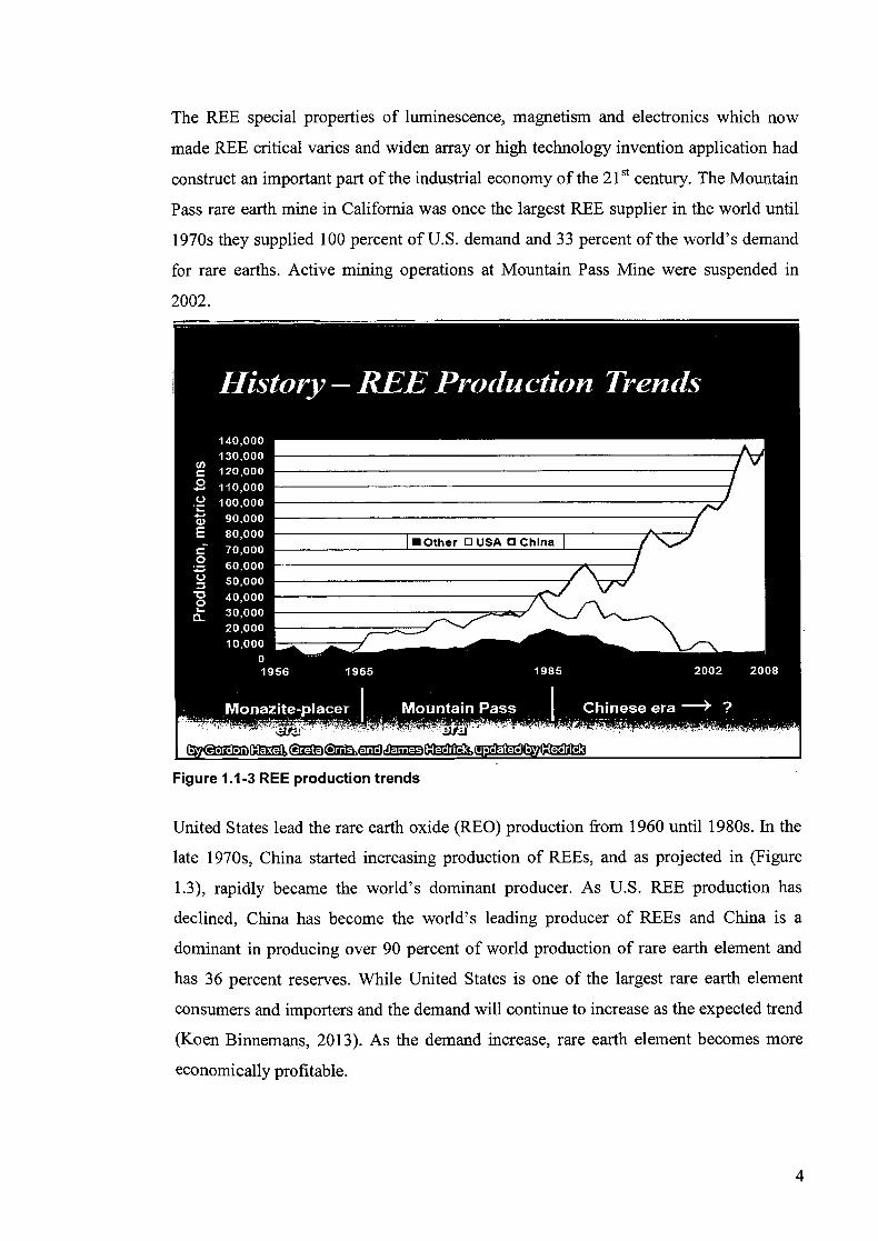
The REE special properties of luminescence, magnetism and electronics which now
made REE critical varies and widen array or high technology invention application had
construct an important part of the industrial economy of the 21St century. The Mountain
Pass rare earth mine in California was once the largest REE supplier in the world until
1970s they supplied 100 percent of U.S. demand and 33 percent of the world's demand
for rare earths. Active mining operations at Mountain Pass Mine were suspended in
2002.
Figure 1.1-3 REE production trends
United States lead the rare earth oxide (REO) production from 1960 until 1980s. In the
late 1970s, China started increasing production of REEs, and as projected in (Figure
1.3), rapidly became the world's dominant producer. As U.S. REE production has
declined, China has become the world's leading producer of REEs and China is a
dominant in producing over 90 percent of world production of rare earth element and
has 36 percent reserves. While United States is one of the largest rare earth element
consumers and importers and the demand will continue to increase as the expected trend
(Koen Binnemans, 2013). As the demand increase, rare earth element becomes more
economically profitable.
4
Nowadays, rare earth element is being disposed in a huge quantity rather than being
recycled or reused. Rare earth element is being imported to European Union (EU) from
a limited procedure. REE had already became an integrated in new technologies,
especially within the clean energy, military, magnets, hybrid car batteries, catalyst,
lighting luminescence and others electronics technologies. It is difficult to get an exact
projection of demand in future, analysts have placed the lower and upper bounds for
annual growth for total REE demand at 5% and 9% over the next 25 years (Alonso,
Sherman, Wallington, Everson, Field, Roth & Kirchain, 2012). Additionally, rare earth
metals are significant in alloying addition to steels. REEs is also very useful in the green
energy sector. For example electric and hybrid cars may contain 20-25. pounds of REE,
which is double that found in a standard gasoline vehicle (I Am Gold Corperation,
2012). REEs widely used in development of the braking systems and electric traction
motors that consist of powerful magnets made from neodymium and dysprosium. REEs
are also used to make high capacity wind turbines, advanced solar panels, high
efficiency lighting, petroleum and pollution control catalysts for automobiles and high
speed rails (Kennedy,J, 2009).
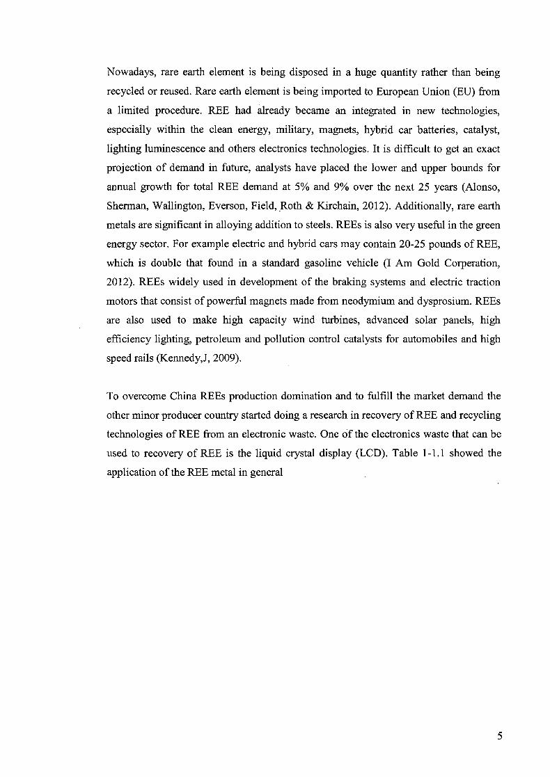
To overcome China REEs production domination and to fulfill the market demand the
other minor producer country started doing a research in recovery of REE and recycling
technologies of REE from an electronic waste. One of the electronics waste that can be
used to recovery of REE is the liquid crystal display (LCD). Table 1-1.1 showed the
application of the REE metal in general
5
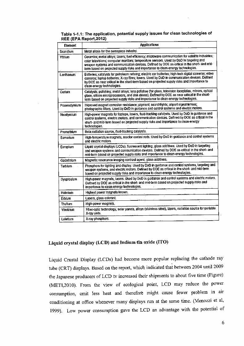
Table 1-1.1: The application, potential supply issues for clean technologies of REE (EPA Reoort.2012)
Element Applications
Scandium Metal alloys for the aerospace industry. Yttrium Ceramics; metal alloys; lasers; fuel efficiency microwave communication for satellite industries;
color televisions; computer monitors; temperature sensors. Used by DOD in targeting and: Weapon systems and communication devices. Defined by DOE as critical in the short- and mid-term based on projected supply risks and importance to clean-energy technologies.
Lanthanum Batteries; catalysts for petroleum refining; electric car batteries; high-tech digital cameras; video cameras; laptop batteries; X-ray films; lasers. Used by DoD in communication devices. Defined by DOE as near critical in the short-term based on projected supply risks and importance to clean-energy technologies
Cerium Catalysts; polishing; metal alloys; lens polishes (for glass, television faceplates, mirrors, optical glass, silicon microprocessors, and disk drives). Defined by DOE as near critical in the short-term based on projected supply risks and importance to clean-energy technologies.
Praseodymium Improved magnet corrosion resistance; pigment, searchlights; airport signal lenses; photographic fitters Used by DoD in guidance and control systems and electric motors
Neodymium High-power magnets for laptops, lasers, fluid-Tracking catalysts. Used by DoD in guidance and control Systems, electric motors, and communication devices. Defined by DOE as critical in the short- and mid-term ibased.on projected supply risks and importance to dean-energy technologies.
Promethium Beta.radiation source,, fluid-Tracking catalysts.
Samarium High-temperature magnets, reactor control rods. Used by DoD in guidance and control systems and electric motors.
Luroptum Liquid crystal displays (LCDS), fluorescent lighting, glass additives. Used by DoD in targeting and weapon systems and communication devices. Defined by DOE as critical in the short- and mid-term based on projected supply risks and importance to clean-energy technologies.
Gadolinium Magnetic resonance imaging contrast agent, glass additives.
Terbium Phosphors for lighting and display. Used by DOD in guidance and control systems, targeting and weapon systems, and electric motors Defined by DOE as critical in The short- and mid-term based on projected supply risks and importance to clean-energy technologies
Dysprosium High-power magnets, lasers. Used by DoD in guidance and control systems and electric motors. Defined by DOE as critical in the short- and mid-term based on projected supply risks and importance to clean-energy technologies.
Holmium Highest power magnets known.
rblum Lasers, glass colorant
Thulium High-power magnets.
Ytterbium Fiber-optic technology, solar panels, alloys (stainless steel) lasers, radiation source for portable X-ray units.
Lutetium X-ray phosphors.
Liquid crystal display (LCD) and Indium tin oxide (ITO)
Liquid Crustal Display (LCDs) had become more popular replacing the cathode ray
tube (CRT) displays. Based on the report, which indicated that between 2004 until 2009
the Japanese producers of LCD tv increased their shipments to about five time (Figure)
(METI,2010). From the view of ecological point, LCD may reduce the power
consumption, emit less heat and therefore might cause fewer problem in air
conditioning at office whenever many displays run at the same time. (Menozzi et a!,
1999). Low power consumption gave the LCD an advantage with the potential of

electromagnetic radiation for causing possible effects on biological matter (Nelson and
Wullert, 1997). As well as the market of the LCD keep increasing (U.S. EPA, 1998), the
life-cycle environmental impacts of LCD treatment methods are thus of interest to both
manufacturers and consumers (Socolof and Kincaid, 2001).
18000
16000
12000 co CL CU J -10000
8000
6000
CD 4000
2000
02004 2005 2006 2007 2008 2009
Year
Figure 1-4: Shipments of Japanese producers for LCD TV sets. Source: METI, 2010.
The indium element (Z=49) is a soft and silvery white metal that was found to be
discovered in 1863 by Ferdinand Reich and Theodor Ritcher and named due to the
indigo color of its spectrum (M.J. Chagnon, 2010). While it is said to be nonhazardous
in commercial use, the metal and the metalloid is known to be severely toxic and
carcinogenic to humans and animals (B.Fowler et.al , 1993). The major sources of
primary indium distribution are found in South America, Canada, China, South Korea
and Japan. Canada has the potential to be the largerst sources of indium while China is
currently the biggest indium producer where about 50 to 60% of the world's indium
production (M.J. Chagnon, 2010). On the other hand, on the consumption side, Japan is
the largest indium consumer, taking 60% of the world supply.
7
1.2 Objectives The following are the objective of this research:
. The aim of this work is to identify REE from the electronic waste by double step
leaching process.
1.3 Scope of this research
The following are the scope of this research:
. The recovery of REE from an electronic waste which is Liquid Crystal Display
(LCD).
• To apply double step leaching in the process in REE recovery.
• Identify the REE from the electronic waste by using XRD
1.4 Main contribution of this work The main contribution of this work is related to recovering or recycling process of REE
from an electronic waste which is LCD.
1.5 Organisation of this thesis The structure of the reminder of the thesis is outlined as follow:
Chapter 2 provides a description of the REE from previous finding based on LCD, the
method of recovery and the acid leaching process.
Chapter 3 gives a review of the double stage leaching approach applied and the
identification of REE by using XRD. The summary methodology of the experiment and
the parameters to be study was reviewed in this aspect.
Chapter 4 is devoted to the finding.
8
2 LITERATURE REVIEW
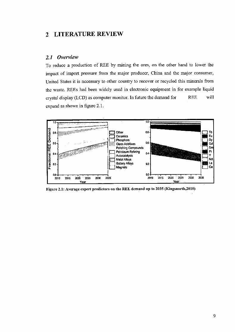
2.1 Overview
To reduce a production of REE by mining the ores, on the other hand to lower the
impact of import pressure from the major producer, China and the major consumer,
United States it is necessary to other country to recover or recycled this minerals from
the waste. REEs had been widely used in electronic equipment in for example liquid
crystal display (LCD) as computer monitor. In future the demand for REE will
expand as shown in figure 2.1.
10 1.0
0.8 1Other 0.8 DTb IWEu •Dceramics
o 0.6Phosphors
0.6 I Li Dy .- w GlassAdditives •Gd
Polishing Compounds [ Sm
04 - Fl Petroleum Refining -J-Pr ALdocatalysts
O [:J Metal Alloys Nd
2 02 fl Battery Alloys 02 La []Magnets Lice
0.0 . . 0.0 . . ........... 2010 2015 2020 2025 2030 2035 2010 2015 2020 2025 2030 2035
Year Year
Figure 2.1: Average expert predictors on the REE demand up to 2035 (Kingsnorth,2010)

Table 2-1.1: Average prices for standard 99% purity of individual REO
Rare Earths Piices (USS/kg)
Rare Earths Oxide Freight On Board (FOB) China Average Price*
2009 2010 2011 2012 Q1/2013 Q2/2013
Lanthanum Oxide 4.88 22.40 104.10 25.20 11.00 8.42
Cerium Oxide 3.88 21.60 102.00 24.70 11.85 8.49
NeodyiniumOxide 19.12 49.50 234.40 123.20 79.15 65.71
Praseodymium Oxide 18.03 48.00 197.30 121.00 85.00 77.64
Sainatium Oxide 3.40 14.40 103.40 64.30 25.00 19.36
Dysprosium Oxide 115.67 231.60 1449.80 1035.60 630.00 561.43
Europium Oxide 492.92 559.80 2842.90 2484.80 1600.00 1110.11
Terbii.un Oxide 361.67 557.80 2334.20 2030.80 1300.00 954.29
In order to oxidize the REE into leachable, a high temperature was
indeed so that the REE can be extract by hydrometallurgical process (D.
Vof3enkaul, 2013).
Rare earth metallurgy divided into several method and technique:
a) Mining
i) Open pit
ii) Underground
iii) In-situ
b) Milling
i) Crushing and grinding
ii) Mixing
c) Physical separation
i) DMS (loparite, monazite)
ii) Magnetic/ electrostatic separation (F/Ti impurities)
iii) Flotation (bastnaesite, monazite)
10
d) Cracking and Precipitation
i) Acid digestion
ii) Alkaline cracking (monazite)
iii) Heating
iv) Precipitation (Na2SO4, CaCO3, Oxalic acid)
e) Rare earth separation
i) Solvent extraction
ii) Ion absorption
iii) Acid leaching
2.2 Introduction This section present the literature review based on the liquid crystal screen (LCD),
previous finding on recycle and recovery of rare earth element (REE) and the acid
leaching process finding.
2.3 Liquid Crystal Display (LCD) and Indium Tin Oxide (ITO)
LCD is divided into to categories, depend on the whether cold cathode fluorescent
lamps or light-emitting diodes been used as the backlight unit. The categories are
conventionally named as LCD and LED respectively. The general structure of the LCD
is presented in (Figure 2-1). ITO is located in the LCD panel. The illustration of the
layered structure of the key components in a panel is presented in (Figure). The majority
of the weight were made up from the glass substrate layer, usually in the range of 1mm
thickness, while the thickness of the liquid crystal, electrode (ITO) and color filter
layers are 5 tm 150 mn and 2 pm respectively (B.Kopacek, 2009).
11

Oute
Printed Ckcuit Board
I \ [] .. .1
LCD MOdUIt
*4k Stand
LCD (dcSldop
Module Fr me LCD Panel-
Light Guide &
OkaiThns
Figure 2-1: The main components within a LCD, and its general structure.
spacer
I 1)0 ii 0 II 0
0 00
V 0
:
liTlid -18W
2::
filter
glass substrate
0
0 ITO
color filter
glass substrate
Figure 2-2: the internal structure and component of an LCD panel
ITO is a thin film acts as semiconductor optoelectronic material, processing special
physical properties of visible light transmission, electric conduction, high hardness and
chemically stable. Therefore ITO is widely used in a lot of optoelectronic equipments
for transparent and conductive display LCD and plasma display panel (PDP), organic
12
light emitting diode (OLED) and touch panel. Almost 60% indium production was used
for the preparation of ITO films (Alfantazi A M, Moskalyk R R, 2003). Usually ITO
film was prepared by DC magnetron sputtering technology using ITO targets.
Nevertheless, 85% of the ITO target which need to be recovered could not be utilized
for magnetron sputtering (Chen J et.al , 2003).
Wastern governments are awakening slowly to the threat of losing access to the key
elements and expert panels in the EU and US have published the report (Critical raw
material for the EU, 2010) that identified 14 raw materials and metal groups including
all the rare earth and platinum group metal as well as antimony, beryllium, cobalt,
gallium, germanium, graphite, indium, tungsten, niobium is abundant and rare earth
crust. The expert team that compiled the report would see the recycling is more efficient
rather than mining ores and keen to promote the research into recycling technically
challenging products.
Globally, most primary indium is recovered as a by-product of processing zinc ores. As
such it is considered as 'at risk' because its supply is dependent on prices of other
commodities. Global secondary indium production increased significantly during the
past several years and now accounts for a greater share of indium production than
primary. This trend is expected to continue in the future. In 2007 (Department of
Natural Resources and Mines, 2014) several major secondary indium producers in
Japan and the Republic of Korea announced plans to further increase their recycling
capacity. The indium market, however, remained in deficit as demand for the metal,
supported largely by indium tin oxide (ITO) demand, continued to outpace supply. In
2007, year-on-year shipments of LCD television panels, which are a major use of
indium, were forecast to increase by 47%, and LCD monitor panels to increase by 24%.
Mainstream LCD devices were also trending toward larger panel sizes, which require
more indium per unit (Department of Natural Resources and Mines, 2014).
Increased manufacturing efficiency and recycling (especially in Japan) maintain a
balance between demand and supply. According to the United Nations Environment
Programme, indium's end-of-life recycling rate is less than 1%. Demand increased as
the use of the metal in LCDs and televisions increased, and supply decreased when
Chinese mining concerns stopped extracting indium from their zinc tailings. In 2002,
the price was US$94 per kilogram. Recent changes in demand and supply have resulted
13
in high and fluctuating prices of indium, which from 2006 to 2009 ranged from
US$382/kg to US$918/kg (Department of Natural Resources and Mines, 2014).
It has been estimated that there are fewer than 14 years left of indium supplies, based on
current rates of extraction, demonstrating the need for additional recycling.
2.4 REE recycle and recovery The electronic waste that contain REEs are typically being disposed rather than being
recycled. All the scrap materials were labeled as hazardous waste and being disposed in
a suitable area with safety handling guideline. Recovery and recycling of magnets will
be more attractive in a future year as the demand of this high quality magnet does keep
increasing as the expected trend a shown in figure 4. It is admitted that 300,000 tons of
REEs was trapped in waste electric and electronics equipment (WEEE) waste streams in
Japan today (EPOW, 2011 a), and Japan is, as mentioned earlier, the only country in the
world where there are some activity on recycling of rare earth magnets to date (Oakdene
Hollins, 2010). Japan nowadays with the collaboration between Honda and Japan
Metals & Chemicals Co., Ltd had already established the recovery of REE from
recycled nickel-metal hydride batteries.
A novel technique was presented before for indium oxide recover without the
difficulties described in method applied before. Efforts to recycle the valuable materials
especially rare metal like indiums (G.Phipps et.al, 2008) from Liquid Crystal Display
(LCD) wastes and indium tin oxide (ITO) targets have been investigated by many
researchers. Most methods on indium recovery have concentrated via acid dissolution or
acid leaching (J.Li et.al , 2009 and Y.Liet.al, 2011), and indium recovery has been
reported.
LCD glass substrate cannot be reused because unresolved thin films cannot be peeled
from the glass surface. The glass used for LCD panel is made of high quality glass and
is expensive due to the difficulty to produce high silica content, low density, large flat
panels, good surface quality, high heat resistance, and dimensional stability glass
panels. Sub- critical water (sub-CW) has been utilized for recovery and/or production of
valuable resources from solid waste and is gaining interest due to its potential as solvent
With hydrolysis power and catalyst for organic reaction. This technique is based on the
14
use of water as medium, at temperatures between its boiling point (100 °C) and its
critical point (374 °C) and at pressures high enough to maintain the liquid state
(Hiroyuki Yoshida et. al, 2014). Sub-critical water treatment in are action time of 5mm
and temperature of 360 1C showed a remarkable 83% (337mg/kg- GL) indium recovery
from CF glass, but7% (22mg/kg-GL)in TFT glass. Optic microscopic images and TOC
analysis implied that sub- CW treatment caused exfoliation of ITO covered with organic
multilayers, which did not dissolve in the sub-CW. This phenomenon is very
advantageous because indium can simply be separated from CF glass and easily
recovered by filtration. High purity indium product can then be produced just by
burning the filtered material, which is small amount, economically. Transparent and
quality glass was simultaneously recovered from CF glass (Hiroyuki Yoshida et.al ,
2014).
15

Table 2.2: Recycling operations, technologies utilized current status and benefits (EPA ReDort. 2012)
Target Feedstock/ Technology Anticipated Time to Benefits (Cost and Company Element to Be Used Commercialization Environmental)
Hitachi Rare earth Automated Anticipates recycling Dry extraction magnets from separation will meet 10% of its method that allows air conditioner process and need by 2013 when processing without compressors dry extraction facility goes online acids; resulting waste and hard disk process water problem. drives Automated
separation process is faster than manual. Cost savings anticipated.
Toyota Hybrid car Unknown Ongoing Main driver is supply batteries concerns Japan's Air conditioners Plans to 2011 No information Shin-Etsu recycle readily available. Chemical recovered
REEs into magnets
Showa Dysprosium and No Estimated output of No inf-ormation Denko KK didymium (a information 800 tons from readily available.
mixture of readily recycling facility praseodymium available. and neodymium)
2.5 Acid leaching
Leaching process will involve the interaction between the sorbent, analyte and the
solvent. Leaching rate of rare earth element basically influence by the solvent
concentration, temperature, time, liquid to solid ratio and also by the stirring agitation
speed during mixing between rare earth element and the solvent. Leaching rate is
directly proportional to those factors. In leaching, there are transport process between
solvent and the surface of element. Leaching mechanism of rare earth is ion exchange
between positive-ion in solution and the surface of rare earth material (A. Zwir-Ferenc,2006) Due to the factor that will affect the leaching rate, the solvent must have high concentration and have high saturation limit and selectivity in order to produce an
optimum quality of extracted product. The most suitable solvent usually used in
leaching of rare earth element was an acidic solution such as HC1, H2SO4, and HNO3.
IV