Embed Size (px)
Citation preview
Freescale SemiconductorApplication Note
© Freescale Semiconductor, Inc., 2009. All rights reserved.
As wireless base station technology continues to evolve, so does the demand for high-performance baseband processing and high-bandwidth interconnect solutions. Emerging standards, such as 3.5G, LTE, and WiMax, are creating a need for clusters of multicore DSPs to deliver the required baseband processing capacity and high-speed serial communication fabrics to address the need for increased speed chip-to-chip and backplane interconnects.
Freescale has solutions for both these interconnect types. Multicore Digital Signal Processor (DSP) solutions based on StarCore® technology combined with PowerQUICC™ and multicore QorIQ™ products have integrated support for Serial RapidIO® fabrics that can meet the processing and high-speed interconnect requirements for next-generation wireless base stations.
The following application note details a procedure for programming and resetting MSC8156 or MSC8144 StarCore DSPs over a serial RapidIO interface from an external host. The application note is supplied with sample application codes in the attached zip file.
Contents1. Introduction . . . . . . . . . . . . . . . . . . . . . . . . . . . . . . . . . 22. System Requirements and Setup . . . . . . . . . . . . . . . . . 33. DSP Programming . . . . . . . . . . . . . . . . . . . . . . . . . . . 64. Resetting the DSP over a RapidIO Interface . . . . . . 145. Additional Functions . . . . . . . . . . . . . . . . . . . . . . . . . 206. Revision History . . . . . . . . . . . . . . . . . . . . . . . . . . . . 21
RapidIO® Technology in Wireless Base Stations: Programming DSPs over a RapidIO Interconnect by: Networking and Multimedia Group
Freescale Semiconductor, Inc.East Kilbride, Scotland
Document Number: AN3661Rev. 0, 1/2009
RapidIO® Technology in Wireless Base Stations: Programming DSPs over a RapidIO Interconnect, Rev. 0
2 Freescale Semiconductor
Introduction
1 IntroductionThe RapidIO architecture is a packet-switched interconnect developed by the embedded processor industry to deliver increased bandwidth and improved reliability for both chip-to-chip and backplane communications links. The RapidIO interconnect specification is administered by the RapidIO Trade Association. There are currently a number of revisions of the RapidIO standard.
This application note focuses on the serial version of the RapidIO standard, known as the serial RapidIO interface. The serial RapidIO interface is a high-speed serial interconnect based on similar specifications for high-speed serial communications standards such as PCI Express and Infiniband. The serial RapidIO interface supports multiple lane implementations, such as ×1 and ×4, where each lane consists of a differential transmit pair and a differential receive pair of data lines. The specification also supports different data rates from 1.0 Gbps and higher. Further details on the serial RapidIO interconnect can be found from the RapidIO Trade Association at http://www.rapidio.org.
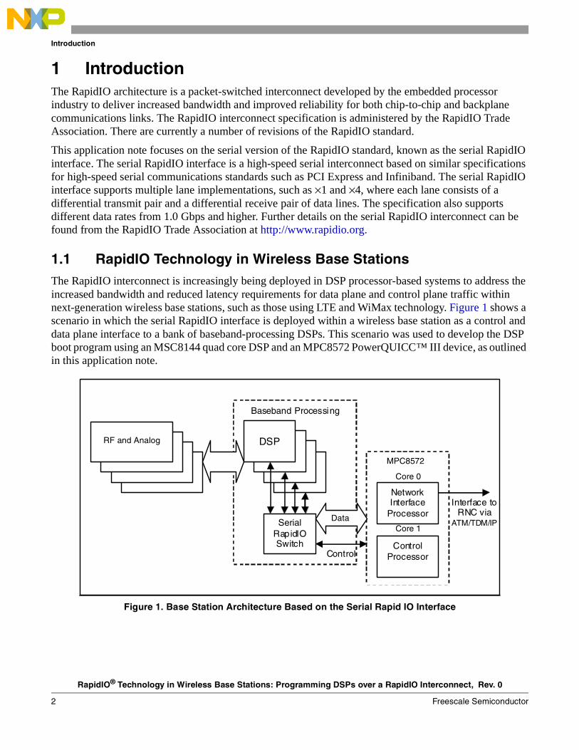
1.1 RapidIO Technology in Wireless Base StationsThe RapidIO interconnect is increasingly being deployed in DSP processor-based systems to address the increased bandwidth and reduced latency requirements for data plane and control plane traffic within next-generation wireless base stations, such as those using LTE and WiMax technology. Figure 1 shows a scenario in which the serial RapidIO interface is deployed within a wireless base station as a control and data plane interface to a bank of baseband-processing DSPs. This scenario was used to develop the DSP boot program using an MSC8144 quad core DSP and an MPC8572 PowerQUICC™ III device, as outlined in this application note.
Figure 1. Base Station Architecture Based on the Serial Rapid IO Interface
DSP
Serial RapidIO Switch
Control Processor
Network Interface
Processor
Baseband Processing
MPC8572
Control
Interface to RNC via
ATM/TDM/IP
RF and Analog
Data
Core 0
Core 1
MPC8572
RapidIO® Technology in Wireless Base Stations: Programming DSPs over a RapidIO Interconnect, Rev. 0
Freescale Semiconductor 3
System Requirements and Setup
1.2 ReferencesFreescale documentation is available from the sources listed on the back page, and the Tundra Tsi578 User Manual is available from the Tundra Semiconductor website at www.tundra.com. The documentation numbers for Freescale documents are included in parentheses for ease of ordering. Some documents may require a non-disclosure agreement. For those documents, contact your local field applications engineer or sales representative to obtain a copy.
• MPC8572E PowerQUICC III™ Host Processor Family Reference Manual (MPC8572ERM)
• MSC8144 Reference Manual (MSC8144RM)
• Serial RapidIO Bring-Up Procedure on PowerQUICC™ III (AN2932)
• MPC8572E Advanced Mezzanine Card User Guide (MPC8572EAMCUG)
• MSC8144AMC-S Advanced Mezzanine Card User Manual (MSC8144AMCSUM)
• MSC8156 Reference Manual (MSC8156RM)
• Tundra Tsi578 User Manual
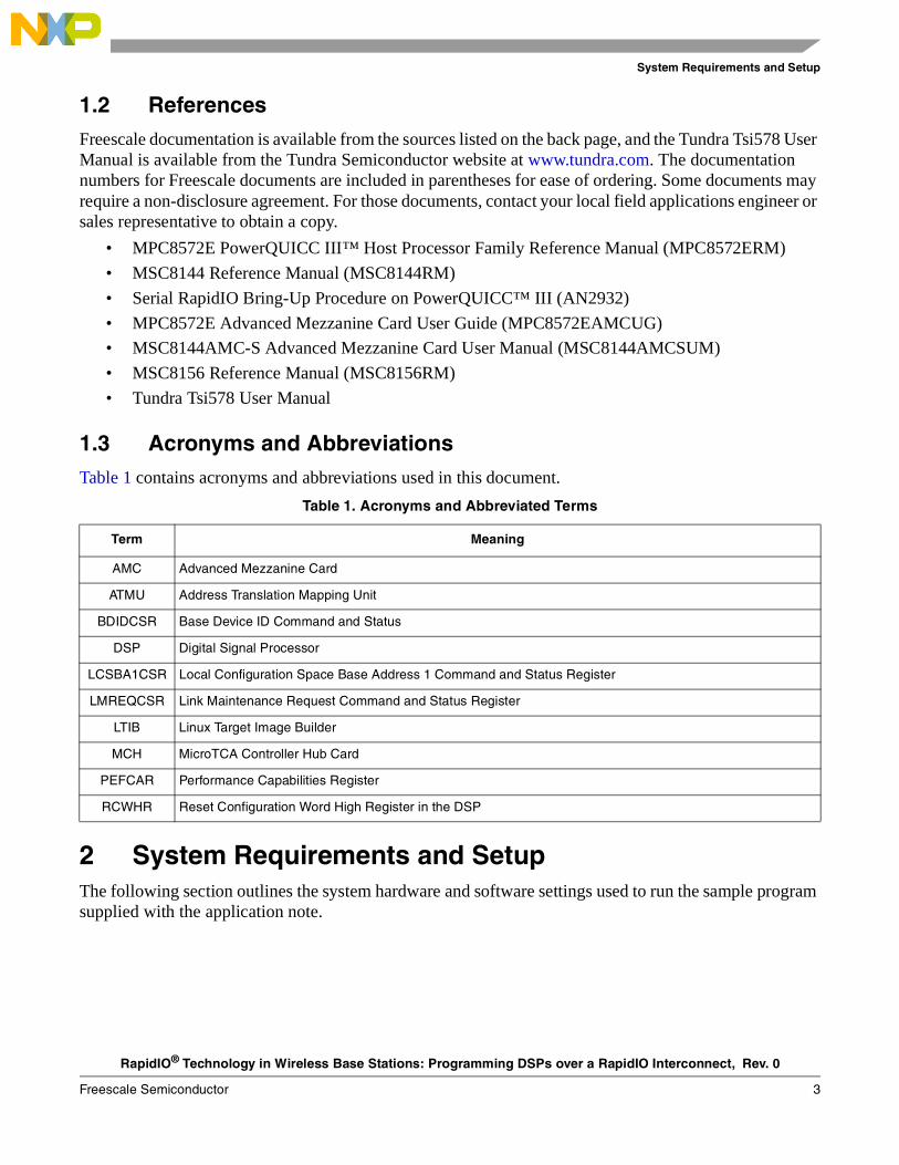
1.3 Acronyms and AbbreviationsTable 1 contains acronyms and abbreviations used in this document.
2 System Requirements and SetupThe following section outlines the system hardware and software settings used to run the sample program supplied with the application note.
Table 1. Acronyms and Abbreviated Terms
Term Meaning
AMC Advanced Mezzanine Card
ATMU Address Translation Mapping Unit
BDIDCSR Base Device ID Command and Status
DSP Digital Signal Processor
LCSBA1CSR Local Configuration Space Base Address 1 Command and Status Register
LMREQCSR Link Maintenance Request Command and Status Register
LTIB Linux Target Image Builder
MCH MicroTCA Controller Hub Card
PEFCAR Performance Capabilities Register
RCWHR Reset Configuration Word High Register in the DSP
RapidIO® Technology in Wireless Base Stations: Programming DSPs over a RapidIO Interconnect, Rev. 0
4 Freescale Semiconductor
System Requirements and Setup
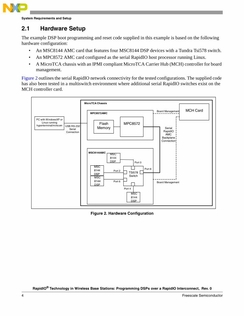
2.1 Hardware SetupThe example DSP boot programming and reset code supplied in this example is based on the following hardware configuration:
• An MSC8144 AMC card that features four MSC8144 DSP devices with a Tundra Tsi578 switch.
• An MPC8572 AMC card configured as the serial RapidIO host processor running Linux.
• A MicroTCA chassis with an IPMI compliant MicroTCA Carrier Hub (MCH) controller for board management.
Figure 2 outlines the serial RapidIO network connectivity for the tested configurations. The supplied code has also been tested in a multiswitch environment where additional serial RapidIO switches exist on the MCH controller card.
Figure 2. Hardware Configuration
Flash Memory
TSi578 Switch
Port 0
Port 2
Port 4
Port 6
MPC8572
Port 8
MCH Card Board Management
Board Management
MPC8572AMC
MSC8144AMC
MicroTCA Chassis
PC with WindowsXP or Linux running
hyperterminal/minicom USB RS-232 Serial
Connection
MSC
8144DSP
MSC8144DSPMSC8144DSP
MSC8144DSP
Serial RapidIO
AMC Backplane Connection
RapidIO® Technology in Wireless Base Stations: Programming DSPs over a RapidIO Interconnect, Rev. 0
Freescale Semiconductor 5
System Requirements and Setup
2.1.1 Switch Settings
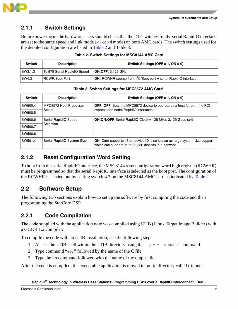
Before powering up the hardware, users should check that the DIP switches for the serial RapidIO interface are set to the same speed and link mode (×1 or ×4 mode) on both AMC cards. The switch settings used for the detailed configuration are listed in Table 2 and Table 3.
2.1.2 Reset Configuration Word SettingTo boot from the serial RapidIO interface, the MSC8144 reset configuration word high register (RCWHR) must be programmed so that the serial RapidIO interface is selected as the boot port. The configuration of the RCWHR is carried out by setting switch 4.3 on the MSC8144 AMC card as indicated by Table 2.
2.2 Software SetupThe following two sections explain how to set up the software by first compiling the code and then programming the StarCore DSP.
2.2.1 Code CompilationThe code supplied with the application note was compiled using LTIB (Linux Target Image Builder) with a GCC 4.1.2 compiler.
To compile the code with an LTIB installation, use the following steps:
1. Access the LTIB shell within the LTIB directory using the “./ltib –m shell” command.
2. Type command “gcc” followed by the name of the C file.
3. Type the –o command followed with the name of the output file.
After the code is compiled, the executable application is moved to an ftp directory called tftpboot.
Table 2. Switch Settings for MSC8144 AMC Card
Switch Description Switch Settings (OFF = 1, ON = 0)
SW3.1:2 Tsi578 Serial RapidIO Speed ON:OFF: 3.125 GHz
SW4.3 RCWR/Boot Port ON: RCWHR source from I2C/Boot port = serial RapidIO interface
Table 3. Switch Settings for MPC8572 AMC Card
Switch Description Switch Settings (OFF = 1, ON = 0)
SW500.4 MPC8572 Host Processor Select
OFF: OFF: Sets the MPC8572 device to operate as a host for both the PCI express and serial RapidIO interfaces
SW500.5
SW500.6 Serial RapidIO Speed Selection
ON:ON:OFF. Serial RapidIO Clock = 125 MHz, 3.125 Gbps (x4)
SW500.7
SW500.6
SW501.4 Serial RapidIO System Size ON: Card supports 16-bit device ID, also known as large system size support, which can support up to 65,536 devices in a network
RapidIO® Technology in Wireless Base Stations: Programming DSPs over a RapidIO Interconnect, Rev. 0
6 Freescale Semiconductor
DSP Programming
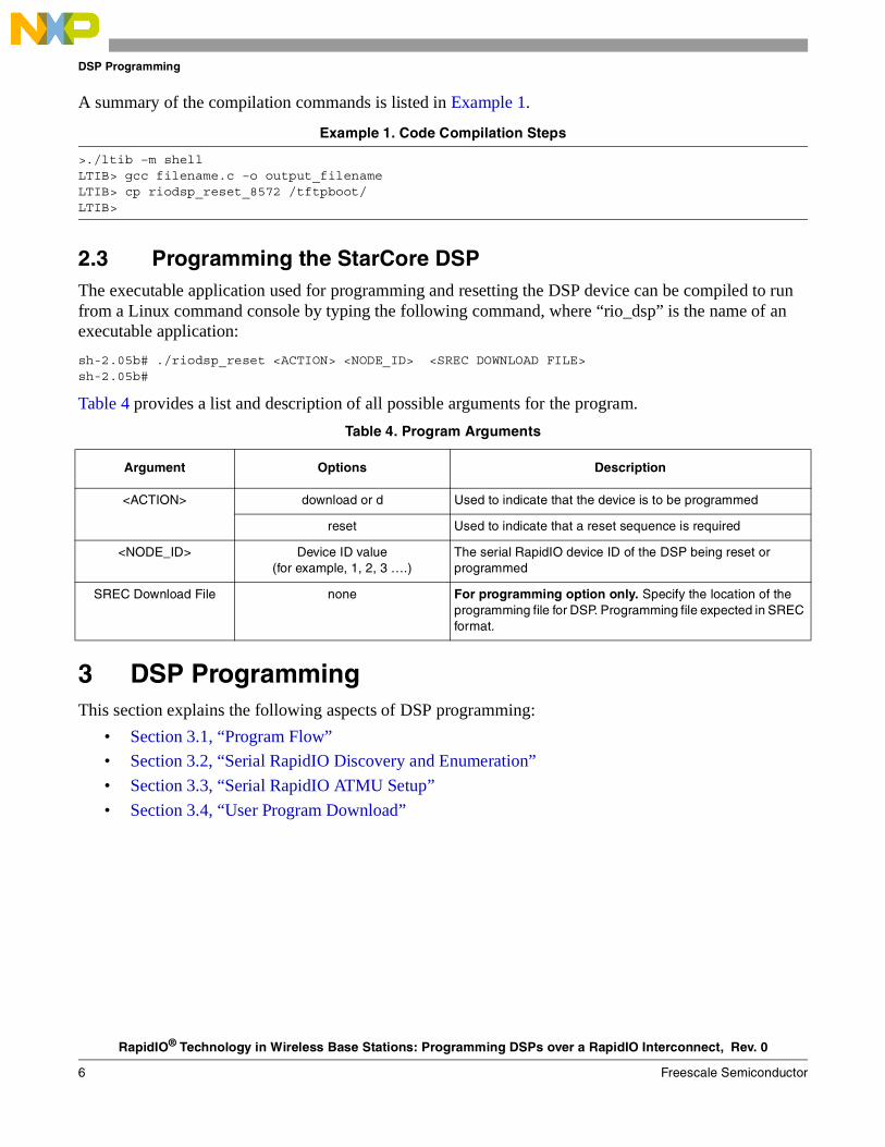
A summary of the compilation commands is listed in Example 1.
Example 1. Code Compilation Steps
>./ltib –m shellLTIB> gcc filename.c –o output_filenameLTIB> cp riodsp_reset_8572 /tftpboot/LTIB>
2.3 Programming the StarCore DSPThe executable application used for programming and resetting the DSP device can be compiled to run from a Linux command console by typing the following command, where “rio_dsp” is the name of an executable application:
sh-2.05b# ./riodsp_reset <ACTION> <NODE_ID> <SREC DOWNLOAD FILE>sh-2.05b#
Table 4 provides a list and description of all possible arguments for the program.
3 DSP ProgrammingThis section explains the following aspects of DSP programming:
• Section 3.1, “Program Flow”
• Section 3.2, “Serial RapidIO Discovery and Enumeration”
• Section 3.3, “Serial RapidIO ATMU Setup”
• Section 3.4, “User Program Download”
Table 4. Program Arguments
Argument Options Description
<ACTION> download or d Used to indicate that the device is to be programmed
reset Used to indicate that a reset sequence is required
<NODE_ID> Device ID value(for example, 1, 2, 3 ….)
The serial RapidIO device ID of the DSP being reset or programmed
SREC Download File none For programming option only. Specify the location of the programming file for DSP. Programming file expected in SREC format.
RapidIO® Technology in Wireless Base Stations: Programming DSPs over a RapidIO Interconnect, Rev. 0
Freescale Semiconductor 7
DSP Programming
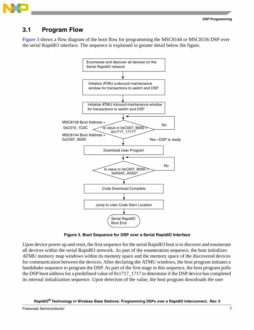
3.1 Program FlowFigure 3 shows a flow diagram of the boot flow for programming the MSC8144 or MSC8156 DSP over the serial RapidIO interface. The sequence is explained in greater detail below the figure.
Figure 3. Boot Sequence for DSP over a Serial RapidIO Interface
Upon device power up and reset, the first sequence for the serial RapidIO host is to discover and enumerate all devices within the serial RapidIO network. As part of the enumeration sequence, the host initializes ATMU memory map windows within its memory space and the memory space of the discovered devices for communication between the devices. After declaring the ATMU windows, the host program initiates a handshake sequence to program the DSP. As part of the first stage in this sequence, the host program polls the DSP boot address for a predefined value of 0x1717_1717 to determine if the DSP device has completed its internal initialization sequence. Upon detection of the value, the host program downloads the user
Enumerate and discover all devices on the Serial RapidIO network
Initialize ATMU outbound maintenance window for transactions to switch and DSP
Initialize ATMU inbound maintenance window for transactions to switch and DSP
Is value in 0xC007_B000 = 0x1717_1717?
Download User Program
Is value in 0xC007_B000 = 0xA5A5_A5A5?
Code Download Complete
Jump to User Code Start Location
Serial RapidIOBoot End
No
Yes—DSP is ready
No
MSC8156 Boot Address =
0xC010_1C0C
MSC8144 Boot Address = 0xC007_B000
RapidIO® Technology in Wireless Base Stations: Programming DSPs over a RapidIO Interconnect, Rev. 0
8 Freescale Semiconductor
DSP Programming
program to the DSP. Once completed, the host program writes 0xA5A5_A5A5 to the boot address location to indicate that it has finished downloading the program code.
On the MSC8156, the boot data location is located in M3 memory with the boot address at location 0xC010_1C00. On the MSC8144, the boot data is located in M2 memory with the boot address at location 0xC007_B000.
3.2 Serial RapidIO Discovery and EnumerationBefore any programming of the DSP can take place, all devices in the serial RapidIO network must be discovered and enumerated with a valid device ID. The details of the serial RapidIO discovery and enumeration sequence are available in AN2932, “Serial RapidIO Bring-up Procedure on PowerQUICC™ III.”
Within the specified hardware configuration, the discovery and enumeration of the serial RapidIO networkis carried out by a Linux RapidIO kernel driver running on the PowerQUICC host. The serial RapidIOkernel driver is an open source kernel driver available from http://www.kernel.org.
Note that within the supplied code example, access to the physical device configuration registers, such as the ATMU window registers on the PowerQUICC™ III device, is carried out by means of the Linux mmap() function. The function provides a user space mapping to the physical registers on the PowerQUICC device using a file descriptor to the Linux driver, located in /dev/mem directory.
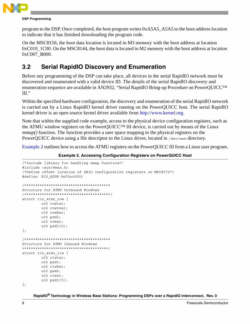
Example 2 outlines how to access the ATMU registers on the PowerQUICC III from a Linux user program.
Example 2. Accessing Configuration Registers on PowerQUICC Host
/*Include library for handling mmap function*/#include <sys/mman.h>/*Define offset location of SRIO configuration registers on MPC8572*/#define RIO_ADDR 0xffec0000
/***************************************Structure for ATMU Outbound Windows/***************************************/struct rio_atmu_row {
u32 rowtar;u32 rowtear;u32 rowbar;u32 pad2;u32 rowar;u32 pad3[3];
};
/***************************************Structure for ATMU Inbound Windows***************************************/struct rio_atmu_riw {
u32 riwtar;u32 pad1;u32 riwbar;u32 pad2;u32 riwar;u32 pad3[3];
};
RapidIO® Technology in Wireless Base Stations: Programming DSPs over a RapidIO Interconnect, Rev. 0
Freescale Semiconductor 9
DSP Programming
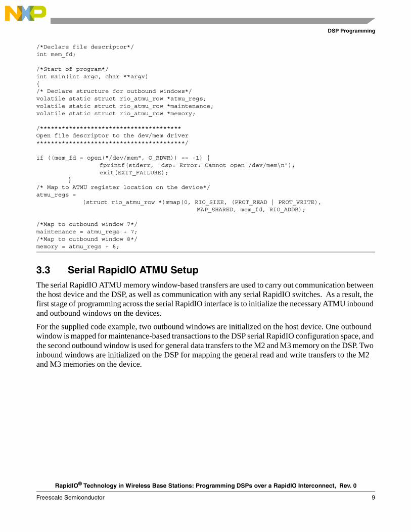
/*Declare file descriptor*/int mem_fd;
/*Start of program*/int main(int argc, char **argv){/* Declare structure for outbound windows*/volatile static struct rio_atmu_row *atmu_regs;volatile static struct rio_atmu_row *maintenance;volatile static struct rio_atmu_row *memory;
/***************************************Open file descriptor to the dev/mem driver*****************************************/
if ((mem_fd = open("/dev/mem", O_RDWR)) == -1) {fprintf(stderr, "dsp: Error: Cannot open /dev/mem\n");exit(EXIT_FAILURE);
}/* Map to ATMU register location on the device*/atmu_regs =
(struct rio_atmu_row *)mmap(0, RIO_SIZE, (PROT_READ | PROT_WRITE),MAP_SHARED, mem_fd, RIO_ADDR);
/*Map to outbound window 7*/maintenance = atmu_regs + 7;/*Map to outbound window 8*/memory = atmu_regs + 8;
3.3 Serial RapidIO ATMU SetupThe serial RapidIO ATMU memory window-based transfers are used to carry out communication between the host device and the DSP, as well as communication with any serial RapidIO switches. As a result, the first stage of programming across the serial RapidIO interface is to initialize the necessary ATMU inbound and outbound windows on the devices.
For the supplied code example, two outbound windows are initialized on the host device. One outbound window is mapped for maintenance-based transactions to the DSP serial RapidIO configuration space, and the second outbound window is used for general data transfers to the M2 and M3 memory on the DSP. Two inbound windows are initialized on the DSP for mapping the general read and write transfers to the M2 and M3 memories on the device.
RapidIO® Technology in Wireless Base Stations: Programming DSPs over a RapidIO Interconnect, Rev. 0
10 Freescale Semiconductor
DSP Programming
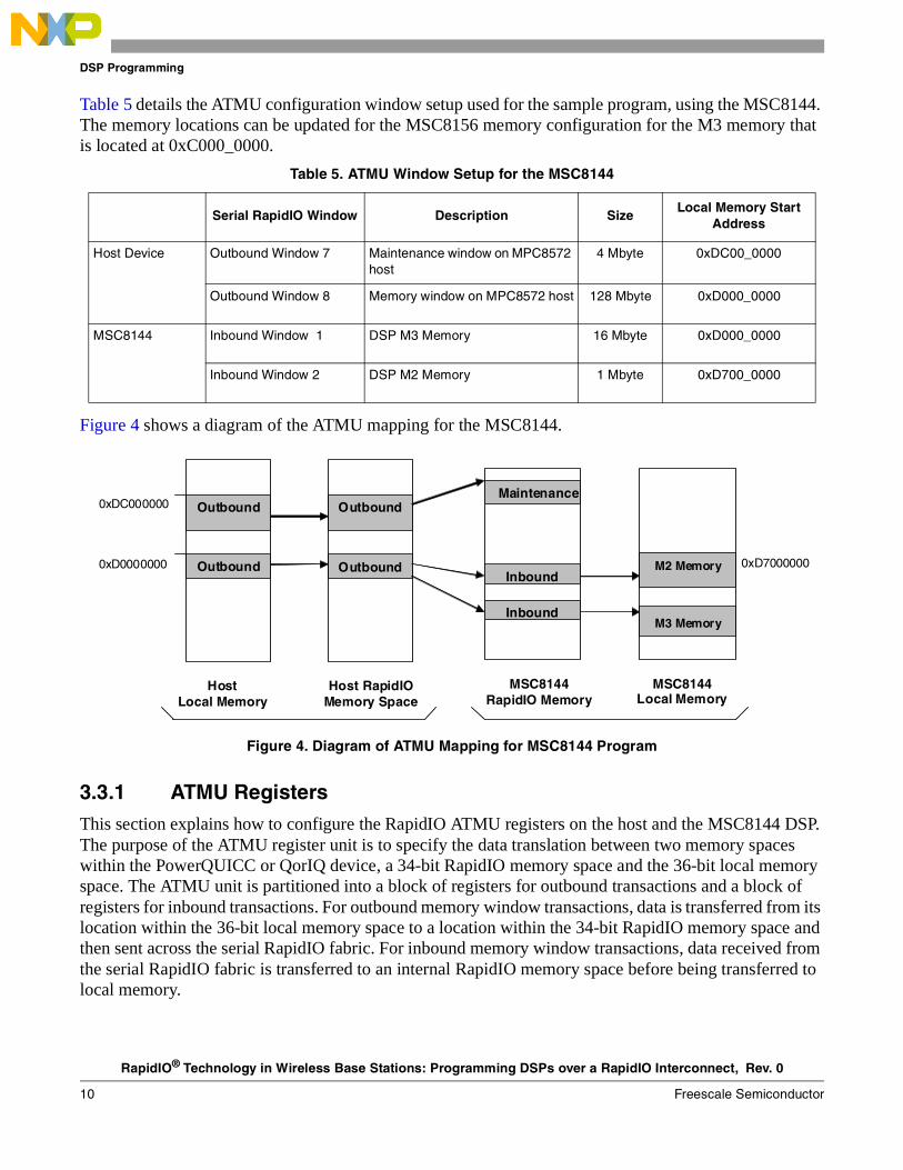
Table 5 details the ATMU configuration window setup used for the sample program, using the MSC8144. The memory locations can be updated for the MSC8156 memory configuration for the M3 memory that is located at 0xC000_0000.
Figure 4 shows a diagram of the ATMU mapping for the MSC8144.
Figure 4. Diagram of ATMU Mapping for MSC8144 Program
3.3.1 ATMU RegistersThis section explains how to configure the RapidIO ATMU registers on the host and the MSC8144 DSP. The purpose of the ATMU register unit is to specify the data translation between two memory spaces within the PowerQUICC or QorIQ device, a 34-bit RapidIO memory space and the 36-bit local memory space. The ATMU unit is partitioned into a block of registers for outbound transactions and a block of registers for inbound transactions. For outbound memory window transactions, data is transferred from its location within the 36-bit local memory space to a location within the 34-bit RapidIO memory space and then sent across the serial RapidIO fabric. For inbound memory window transactions, data received from the serial RapidIO fabric is transferred to an internal RapidIO memory space before being transferred to local memory.
Table 5. ATMU Window Setup for the MSC8144
Serial RapidIO Window Description SizeLocal Memory Start
Address
Host Device Outbound Window 7 Maintenance window on MPC8572 host
4 Mbyte 0xDC00_0000
Outbound Window 8 Memory window on MPC8572 host 128 Mbyte 0xD000_0000
MSC8144 Inbound Window 1 DSP M3 Memory 16 Mbyte 0xD000_0000
Inbound Window 2 DSP M2 Memory 1 Mbyte 0xD700_0000
0xD0000000
0xDC000000
Host Local Memory
Host RapidIO Memory Space
Outbound
Outbound
Outbound
Outbound Inbound
InboundM3 Memory
M2 Memory
Maintenance
MSC8144RapidIO Memory
MSC8144 Local Memory
0xD7000000
RapidIO® Technology in Wireless Base Stations: Programming DSPs over a RapidIO Interconnect, Rev. 0
Freescale Semiconductor 11
DSP Programming
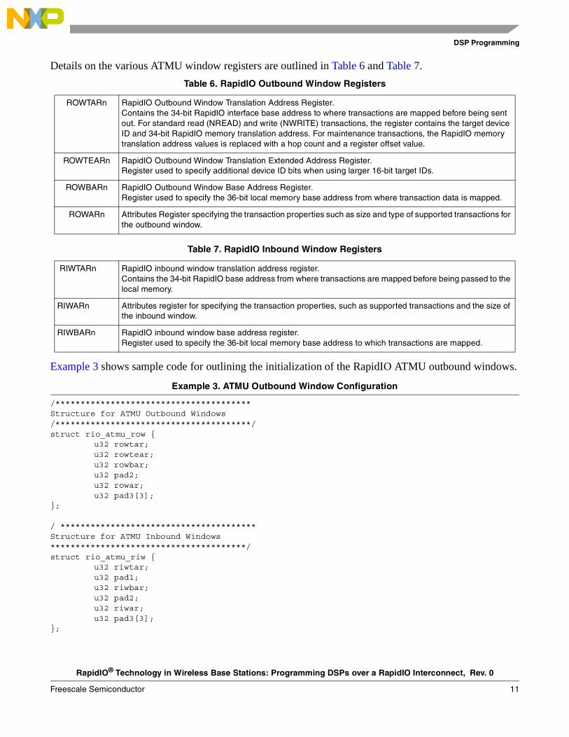
Details on the various ATMU window registers are outlined in Table 6 and Table 7.
Example 3 shows sample code for outlining the initialization of the RapidIO ATMU outbound windows.
Example 3. ATMU Outbound Window Configuration
/***************************************Structure for ATMU Outbound Windows/***************************************/struct rio_atmu_row {
u32 rowtar;u32 rowtear;u32 rowbar;u32 pad2;u32 rowar;u32 pad3[3];
};
/ ***************************************Structure for ATMU Inbound Windows***************************************/struct rio_atmu_riw {
u32 riwtar;u32 pad1;u32 riwbar;u32 pad2;u32 riwar;u32 pad3[3];
};
Table 6. RapidIO Outbound Window Registers
ROWTARn RapidIO Outbound Window Translation Address Register. Contains the 34-bit RapidIO interface base address to where transactions are mapped before being sent out. For standard read (NREAD) and write (NWRITE) transactions, the register contains the target device ID and 34-bit RapidIO memory translation address. For maintenance transactions, the RapidIO memory translation address values is replaced with a hop count and a register offset value.
ROWTEARn RapidIO Outbound Window Translation Extended Address Register.Register used to specify additional device ID bits when using larger 16-bit target IDs.
ROWBARn RapidIO Outbound Window Base Address Register.Register used to specify the 36-bit local memory base address from where transaction data is mapped.
ROWARn Attributes Register specifying the transaction properties such as size and type of supported transactions for the outbound window.
Table 7. RapidIO Inbound Window Registers
RIWTARn RapidIO inbound window translation address register. Contains the 34-bit RapidIO base address from where transactions are mapped before being passed to the local memory.
RIWARn Attributes register for specifying the transaction properties, such as supported transactions and the size of the inbound window.
RIWBARn RapidIO inbound window base address register. Register used to specify the 36-bit local memory base address to which transactions are mapped.
RapidIO® Technology in Wireless Base Stations: Programming DSPs over a RapidIO Interconnect, Rev. 0
12 Freescale Semiconductor
DSP Programming
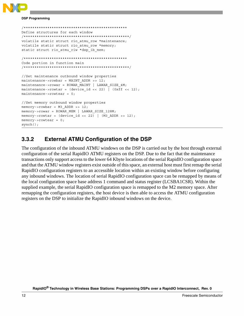
/************************************************Define structures for each window/*************************************************/volatile static struct rio_atmu_row *maintenance;volatile static struct rio_atmu_row *memory;static struct rio_atmu_riw *dsp_ib_mem;
/************************************************Code portion in function main/*************************************************/
//Set maintenance outbound window propertiesmaintenance->rowbar = MAINT_ADDR >> 12;maintenance->rowar = ROWAR_MAINT | LAWAR_SIZE_4M;maintenance->rowtar = (device_id << 22) | (0xff << 12);maintenance->rowtear = 0;
//Set memory outbound window propertiesmemory->rowbar = M3_ADDR >> 12;memory->rowar = ROWAR_MEM | LAWAR_SIZE_128M;memory->rowtar = (device_id << 22) | (M3_ADDR >> 12);memory->rowtear = 0;synch();
3.3.2 External ATMU Configuration of the DSP
The configuration of the inbound ATMU windows on the DSP is carried out by the host through external configuration of the serial RapidIO ATMU registers on the DSP. Due to the fact that the maintenance transactions only support access to the lower 64 Kbyte locations of the serial RapidIO configuration space and that the ATMU window registers exist outside of this space, an external host must first remap the serial RapidIO configuration registers to an accessible location within an existing window before configuring any inbound windows. The location of serial RapidIO configuration space can be remapped by means of the local configuration space base address 1 command and status register (LCSBA1CSR). Within the supplied example, the serial RapidIO configuration space is remapped to the M2 memory space. After remapping the configuration registers, the host device is then able to access the ATMU configuration registers on the DSP to initialize the RapidIO inbound windows on the device.
RapidIO® Technology in Wireless Base Stations: Programming DSPs over a RapidIO Interconnect, Rev. 0
Freescale Semiconductor 13
DSP Programming
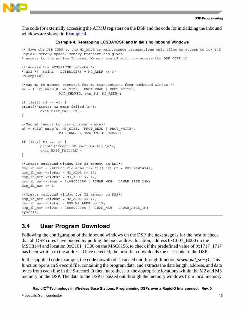
The code for externally accessing the ATMU registers on the DSP and the code for initializing the inbound windows are shown in Example 4.
Example 4. Remapping LCSBA1CSR and Initializing Inbound Windows
/* Move the DSP IMMR to the M2_ADDR as maintenance transactions only allow us access to low 64K RapidIO memory space. Memory transactions gives* access to the entire Internal Memory map m2 will now access the DSP CCSR.*/
/* Access the LCSBA1CSR register*/*(u32 *) (maint + LCSBA1CSR) = M2_ADDR >> 3;usleep(10);
/*Map m2 to memory reserved for m2 transactions from outbound window.*/m2 = (u32) mmap(0, M2_SIZE, (PROT_READ | PROT_WRITE),
MAP_SHARED, mem_fd, M2_ADDR);
if ((s32) m2 == -1) {printf("Error: M2 mmap failed.\n");
exit(EXIT_FAILURE);}
/*Map m3 memory to user program space*/m3 = (u32) mmap(0, M3_SIZE, (PROT_READ | PROT_WRITE),
MAP_SHARED, mem_fd, M3_ADDR);
if ((s32) m3 == -1) {printf("Error: M3 mmap failed.\n");exit(EXIT_FAILURE);
}
/*Create outbound window for M3 memory on DSP*/dsp_ib_mem = (struct rio_atmu_riw *)((u32) m2 + DSP_RIWTAR4);dsp_ib_mem->riwbar = M3_ADDR >> 12;dsp_ib_mem->riwtar = M3_ADDR >> 12;dsp_ib_mem->riwar = 0x08000000 | RIWAR_MEM | LAWAR_SIZE_16M;dsp_ib_mem += 1;
/*Create outbound window for M2 memory on DSP*/dsp_ib_mem->riwbar = M2_ADDR >> 12;dsp_ib_mem->riwtar = DSP_M2_ADDR >> 12;dsp_ib_mem->riwar = 0x08000000 | RIWAR_MEM | LAWAR_SIZE_1M;synch();
3.4 User Program DownloadFollowing the configuration of the inbound windows on the DSP, the next stage is for the host to check that all DSP cores have booted by polling the boot address location, address 0xC007_B000 on the MSC8144 and location 0xC101_1C00 on the MSC8156, to check if the predefined value of 0x1717_1717 has been written to the address. Once detected, the host then downloads the user code to the DSP.
In the supplied code example, the code download is carried out through function download_srec(). This function opens an S-record file, containing the program data, and extracts the data length, address, and data bytes from each line in the S-record. It then maps these to the appropriate locations within the M2 and M3 memory on the DSP. The data to the DSP is passed out through the memory windows from local memory
RapidIO® Technology in Wireless Base Stations: Programming DSPs over a RapidIO Interconnect, Rev. 0
14 Freescale Semiconductor
Resetting the DSP over a RapidIO Interface
location 0xD000_0000 on the host. After all the data is downloaded to the DSP, the host writes the value 0xA5A5_A5A5 to the boot address location on the DSP, to indicate the end of the download. The DSP accepts the program data through serial RapidIO write (NWRITE) operations by means of the ATMU inbound windows. During the download, the DSP polls address 0xC007_B000 to check for the completion of the download. Once the value is detected, the DSP performs some clean-up tasks, such as disabling interrupts, before reading the location of the user program, which is written by the host to location 0xC007_B010 on the MSC8144 or location 0xC010_1C10 on the MSC8156.
4 Resetting the DSP over a RapidIO InterfaceThis section explains the following components of resetting the DSP over a RapidIO interface:
• Section 4.1, “Reset Sequence Flow”
• Section 4.2, “ATMU Window Setup”
• Section 4.3, “Device Identification”
• Section 4.4, “Reset Sequence”
4.1 Reset Sequence FlowWhen developing with the MSC8144 or MSC8156 DSP, you must reset the device to update or change the user code running on the device. A hard reset to the DSP can be generated by sending a RapidIO link reset request from a neighboring device, which is connected to the DSP over the serial RapidIO interface. A hard reset sequence not only resets all cores on the DSP but also resets the RapidIO device ID and configuration settings on the device. As a result, after applying the reset the RapidIO host processor must re-enumerate the DSP before continuing with reprogramming the device.
RapidIO® Technology in Wireless Base Stations: Programming DSPs over a RapidIO Interconnect, Rev. 0
Freescale Semiconductor 15
Resetting the DSP over a RapidIO Interface
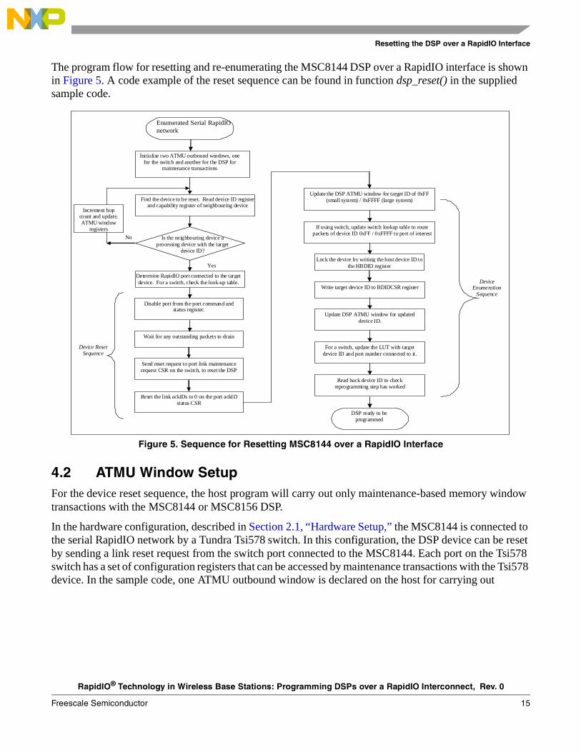
The program flow for resetting and re-enumerating the MSC8144 DSP over a RapidIO interface is shown in Figure 5. A code example of the reset sequence can be found in function dsp_reset() in the supplied sample code.
Figure 5. Sequence for Resetting MSC8144 over a RapidIO Interface
4.2 ATMU Window SetupFor the device reset sequence, the host program will carry out only maintenance-based memory window transactions with the MSC8144 or MSC8156 DSP.
In the hardware configuration, described in Section 2.1, “Hardware Setup,” the MSC8144 is connected to the serial RapidIO network by a Tundra Tsi578 switch. In this configuration, the DSP device can be reset by sending a link reset request from the switch port connected to the MSC8144. Each port on the Tsi578 switch has a set of configuration registers that can be accessed by maintenance transactions with the Tsi578 device. In the sample code, one ATMU outbound window is declared on the host for carrying out
Device Reset Sequence
Initialise two ATMU outbound windows, one for the switch and another for the DSP for
maintenance transactions
Find the device to be reset. Read device ID register and capability register of neighbouring device
Is the neighbouring device a processing device with the target
device ID?
No
Yes
DSP ready to be programmed
Enumerated SRIO network
Increment hop count and update. ATMU window
registers
Determine RapidIO port connected to the target device. For a switch, check the look-up table.
Send reset request to port link maintenance request CSR on the switch, to reset the DSP
Reset the link ackIDs to 0 on the port ackID status CSR
Update the DSP ATMU window for target ID of 0xFF (small system) / 0xFFFF (large system)
If using switch, update switch lookup table to route packets of device ID 0xFF / 0xFFFF to port of interest
Write target device ID to BDIDCSR register
Update DSP ATMU window for updated device ID.
For a switch, update the LUT with target device ID and port number connected to it.
Read back device ID to check reprogramming step has worked
Disable port from the port command and status register.
Wait for any outstanding packets to drain
Lock the device by writing the host device ID to the HBDID register
Device Enumeration
Sequence
Enumerated Serial RapidIOnetwork
RapidIO® Technology in Wireless Base Stations: Programming DSPs over a RapidIO Interconnect, Rev. 0
16 Freescale Semiconductor
Resetting the DSP over a RapidIO Interface
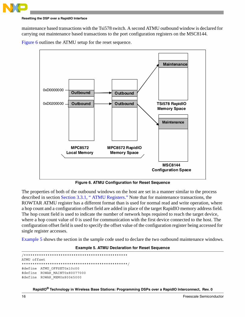
maintenance based transactions with the Tsi578 switch. A second ATMU outbound window is declared for carrying out maintenance based transactions to the port configuration registers on the MSC8144.
Figure 6 outlines the ATMU setup for the reset sequence.
Figure 6. ATMU Configuration for Reset Sequence
The properties of both of the outbound windows on the host are set in a manner similar to the process described in section Section 3.3.1, “ ATMU Registers.” Note that for maintenance transactions, the ROWTAR ATMU register has a different format than is used for normal read and write operation, where a hop count and a configuration offset field are added in place of the target RapidIO memory address field. The hop count field is used to indicate the number of network hops required to reach the target device, where a hop count value of 0 is used for communication with the first device connected to the host. The configuration offset field is used to specify the offset value of the configuration register being accessed for single register accesses.
Example 5 shows the section in the sample code used to declare the two outbound maintenance windows.
Example 5. ATMU Declaration for Reset Sequence
/************************************************ATMU offset*************************************************/#define ATMU_OFFSET0x10c00#define ROWAR_MAINT0x80077000#define ROWAR_MEM0x80045000
0xD0000000
0xD0200000
MPC8572 Local Memory
MPC8572 RapidIO Memory Space
Outbound
Outbound
Maintenance
MSC8144 Configuration Space
TSi578 RapidIO Memory Space
Outbound
Outbound
Maintenance
RapidIO® Technology in Wireless Base Stations: Programming DSPs over a RapidIO Interconnect, Rev. 0
Freescale Semiconductor 17
Resetting the DSP over a RapidIO Interface
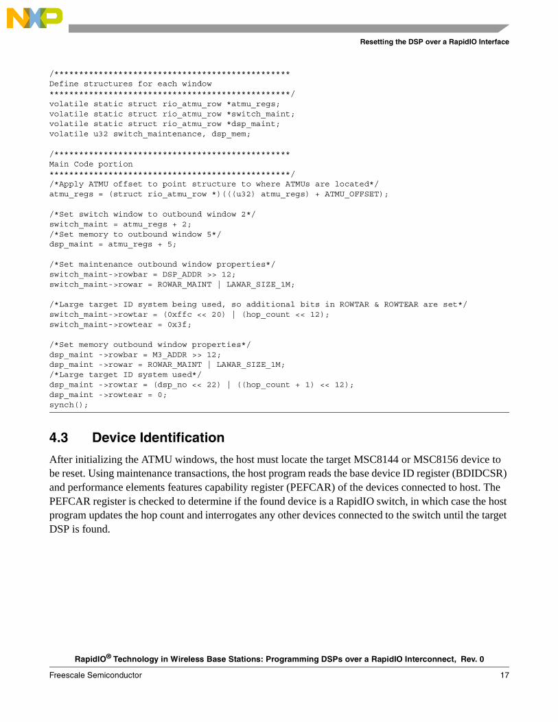
/************************************************Define structures for each window*************************************************/volatile static struct rio_atmu_row *atmu_regs;volatile static struct rio_atmu_row *switch_maint;volatile static struct rio_atmu_row *dsp_maint;volatile u32 switch_maintenance, dsp_mem;
/************************************************Main Code portion*************************************************//*Apply ATMU offset to point structure to where ATMUs are located*/atmu_regs = (struct rio_atmu_row *)(((u32) atmu_regs) + ATMU_OFFSET);
/*Set switch window to outbound window 2*/switch_maint = atmu_regs + 2;/*Set memory to outbound window 5*/dsp_maint = atmu_regs + 5;
/*Set maintenance outbound window properties*/switch_maint->rowbar = DSP_ADDR >> 12;switch_maint->rowar = ROWAR_MAINT | LAWAR_SIZE_1M;
/*Large target ID system being used, so additional bits in ROWTAR & ROWTEAR are set*/switch_maint->rowtar = (0xffc << 20) | (hop_count << 12);switch_maint->rowtear = 0x3f;
/*Set memory outbound window properties*/dsp_maint ->rowbar = M3_ADDR >> 12;dsp_maint ->rowar = ROWAR_MAINT | LAWAR_SIZE_1M;/*Large target ID system used*/dsp_maint ->rowtar = (dsp_no << 22) | ((hop_count + 1) << 12);dsp_maint ->rowtear = 0;synch();
4.3 Device Identification
After initializing the ATMU windows, the host must locate the target MSC8144 or MSC8156 device to be reset. Using maintenance transactions, the host program reads the base device ID register (BDIDCSR) and performance elements features capability register (PEFCAR) of the devices connected to host. The PEFCAR register is checked to determine if the found device is a RapidIO switch, in which case the host program updates the hop count and interrogates any other devices connected to the switch until the target DSP is found.
RapidIO® Technology in Wireless Base Stations: Programming DSPs over a RapidIO Interconnect, Rev. 0
18 Freescale Semiconductor
Resetting the DSP over a RapidIO Interface
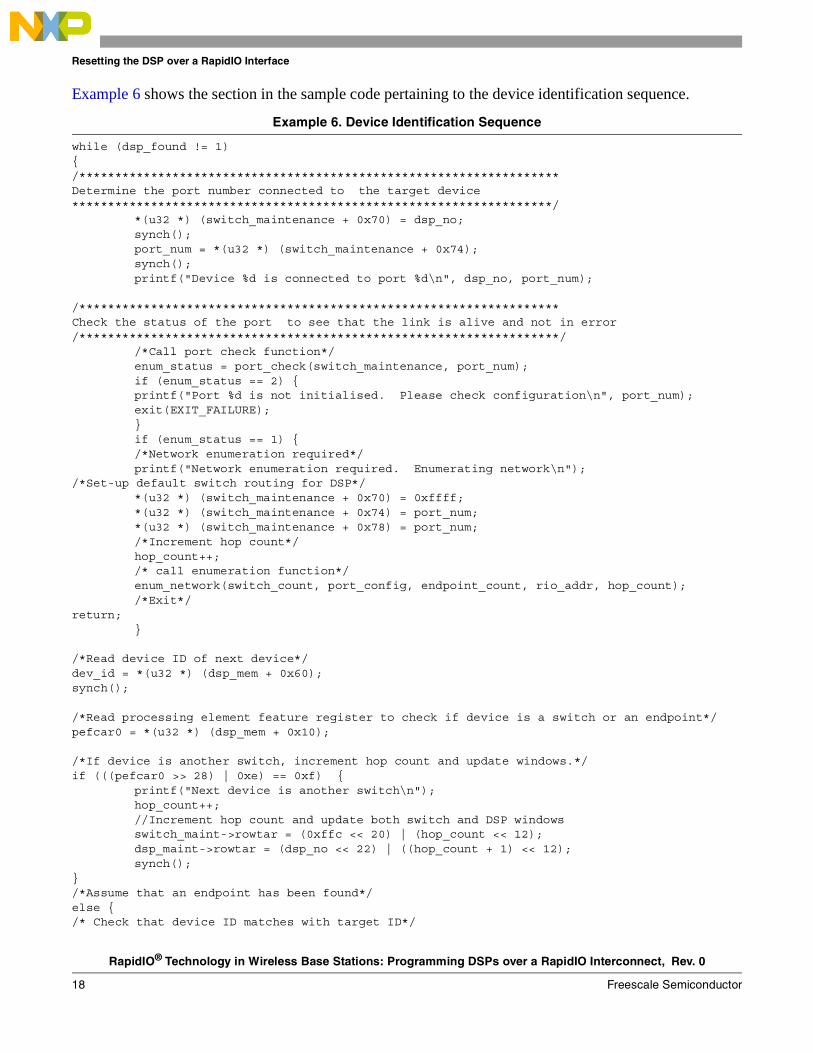
Example 6 shows the section in the sample code pertaining to the device identification sequence.
Example 6. Device Identification Sequence
while (dsp_found != 1) {/*******************************************************************Determine the port number connected to the target device*******************************************************************/
*(u32 *) (switch_maintenance + 0x70) = dsp_no;synch();port_num = *(u32 *) (switch_maintenance + 0x74);synch();printf("Device %d is connected to port %d\n", dsp_no, port_num);
/*******************************************************************Check the status of the port to see that the link is alive and not in error/*******************************************************************/
/*Call port check function*/enum_status = port_check(switch_maintenance, port_num);if (enum_status == 2) {printf("Port %d is not initialised. Please check configuration\n", port_num);exit(EXIT_FAILURE);}if (enum_status == 1) {/*Network enumeration required*/printf("Network enumeration required. Enumerating network\n");
/*Set-up default switch routing for DSP*/*(u32 *) (switch_maintenance + 0x70) = 0xffff;*(u32 *) (switch_maintenance + 0x74) = port_num;*(u32 *) (switch_maintenance + 0x78) = port_num;/*Increment hop count*/hop_count++;/* call enumeration function*/enum_network(switch_count, port_config, endpoint_count, rio_addr, hop_count);/*Exit*/
return;}
/*Read device ID of next device*/dev_id = *(u32 *) (dsp_mem + 0x60);synch();
/*Read processing element feature register to check if device is a switch or an endpoint*/pefcar0 = *(u32 *) (dsp_mem + 0x10);
/*If device is another switch, increment hop count and update windows.*/if (((pefcar0 >> 28) | 0xe) == 0xf) {
printf("Next device is another switch\n");hop_count++;//Increment hop count and update both switch and DSP windowsswitch_maint->rowtar = (0xffc << 20) | (hop_count << 12);dsp_maint->rowtar = (dsp_no << 22) | ((hop_count + 1) << 12);synch();
}/*Assume that an endpoint has been found*/else {/* Check that device ID matches with target ID*/
RapidIO® Technology in Wireless Base Stations: Programming DSPs over a RapidIO Interconnect, Rev. 0
Freescale Semiconductor 19
Resetting the DSP over a RapidIO Interface
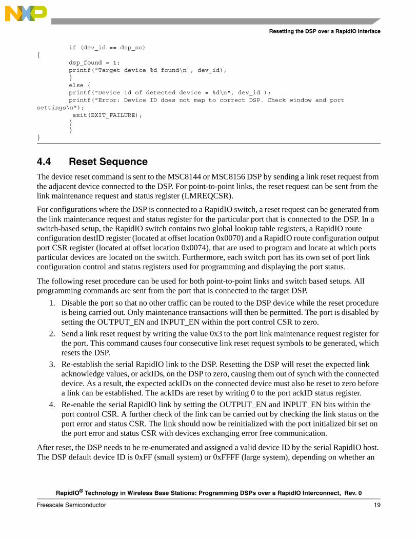
if (dev_id == dsp_no) {
dsp_found = 1;printf("Target device %d found\n", dev_id);}else {printf("Device id of detected device = %d\n", dev_id );printf("Error: Device ID does not map to correct DSP. Check window and port
settings\n"); exit(EXIT_FAILURE);}}
}
4.4 Reset SequenceThe device reset command is sent to the MSC8144 or MSC8156 DSP by sending a link reset request from the adjacent device connected to the DSP. For point-to-point links, the reset request can be sent from the link maintenance request and status register (LMREQCSR).
For configurations where the DSP is connected to a RapidIO switch, a reset request can be generated from the link maintenance request and status register for the particular port that is connected to the DSP. In a switch-based setup, the RapidIO switch contains two global lookup table registers, a RapidIO route configuration destID register (located at offset location 0x0070) and a RapidIO route configuration output port CSR register (located at offset location 0x0074), that are used to program and locate at which ports particular devices are located on the switch. Furthermore, each switch port has its own set of port link configuration control and status registers used for programming and displaying the port status.
The following reset procedure can be used for both point-to-point links and switch based setups. All programming commands are sent from the port that is connected to the target DSP.
1. Disable the port so that no other traffic can be routed to the DSP device while the reset procedure is being carried out. Only maintenance transactions will then be permitted. The port is disabled by setting the OUTPUT_EN and INPUT_EN within the port control CSR to zero.
2. Send a link reset request by writing the value 0x3 to the port link maintenance request register for the port. This command causes four consecutive link reset request symbols to be generated, which resets the DSP.
3. Re-establish the serial RapidIO link to the DSP. Resetting the DSP will reset the expected link acknowledge values, or ackIDs, on the DSP to zero, causing them out of synch with the connected device. As a result, the expected ackIDs on the connected device must also be reset to zero before a link can be established. The ackIDs are reset by writing 0 to the port ackID status register.
4. Re-enable the serial RapidIO link by setting the OUTPUT_EN and INPUT_EN bits within the port control CSR. A further check of the link can be carried out by checking the link status on the port error and status CSR. The link should now be reinitialized with the port initialized bit set on the port error and status CSR with devices exchanging error free communication.
After reset, the DSP needs to be re-enumerated and assigned a valid device ID by the serial RapidIO host. The DSP default device ID is 0xFF (small system) or 0xFFFF (large system), depending on whether an
RapidIO® Technology in Wireless Base Stations: Programming DSPs over a RapidIO Interconnect, Rev. 0
20 Freescale Semiconductor
Additional Functions
8-bit or 16-bit transport format is used within the serial RapidIO network. The re-enumeration sequence is accomplished through the following steps.
1. If using a RapidIO switch-based connection to the DSP, reprogram the switch lookup table to allow the switch to direct packets with the device ID 0xFF/0xFFFF to the relevant port connected to the recently reset DSP. The global switch lookup table can be updated by writing the device ID of 0xFF or 0xFFFF to the RapidIO route configuration DestID register (located at offset 0x0070) and by writing the target port number to the RapidIO route configuration output port CSR (located at 0x0074) on the switch. This procedure is not necessary where a point-to-point connection exists between the host and the DSP.
2. Update the ATMU ROWTAR and ROWTEAR of the outbound maintenance window to the DSP for a device ID of 0xFF or 0xFFFF. After updating the ATMU registers, the software should again be able to carry out maintenance transactions to the DSP.
3. Access the host base device ID lock CSR register on the DSP.
4. Lock the device to the host by writing the host device ID to the register.
5. Update the base device ID register on the DSP to reflect the original device ID of the DSP before it was reset.
6. If using a switch connection to the DSP, update the switch look-up table registers to route packets for the DSP device ID to the relevant port by updating the RIO route configuration destID and RapidIO route configuration output port CSR.
7. Update the device ID parameter on ATMU ROWTAR and ROWTEAR for the DSP outbound window.
8. Carry out a maintenance read of the base device ID register on the DSP to check that the device ID has been successfully applied to the DSP.
Following a successful check, the DSP is ready to be reprogrammed. The programming steps for the recently reset DSP are the same as those outlined in Section 2.3, “ Programming the StarCore DSP.”
5 Additional FunctionsIn addition to the DSP programming and reset steps outlined in the previous steps, the sample code features additional functions used for checking the status of a Serial RapidIO link and enumerating a particular link after a hot insertion.
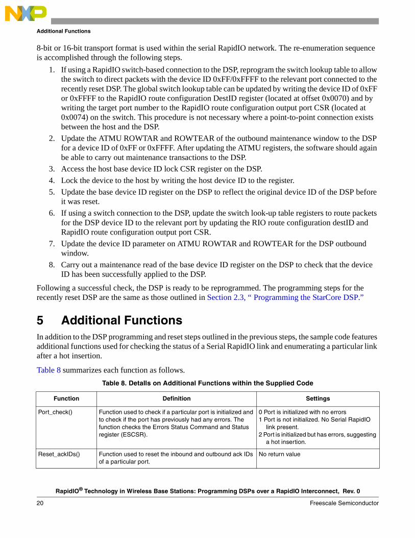
Table 8 summarizes each function as follows.
Table 8. DetaIls on Additional Functions within the Supplied Code
Function Definition Settings
Port_check() Function used to check if a particular port is initialized and to check if the port has previously had any errors. The function checks the Errors Status Command and Status register (ESCSR).
0 Port is initialized with no errors1 Port is not initialized. No Serial RapidIO
link present. 2 Port is initialized but has errors, suggesting
a hot insertion.
Reset_ackIDs() Function used to reset the inbound and outbound ack IDs of a particular port.
No return value
RapidIO® Technology in Wireless Base Stations: Programming DSPs over a RapidIO Interconnect, Rev. 0
Freescale Semiconductor 21
Revision History
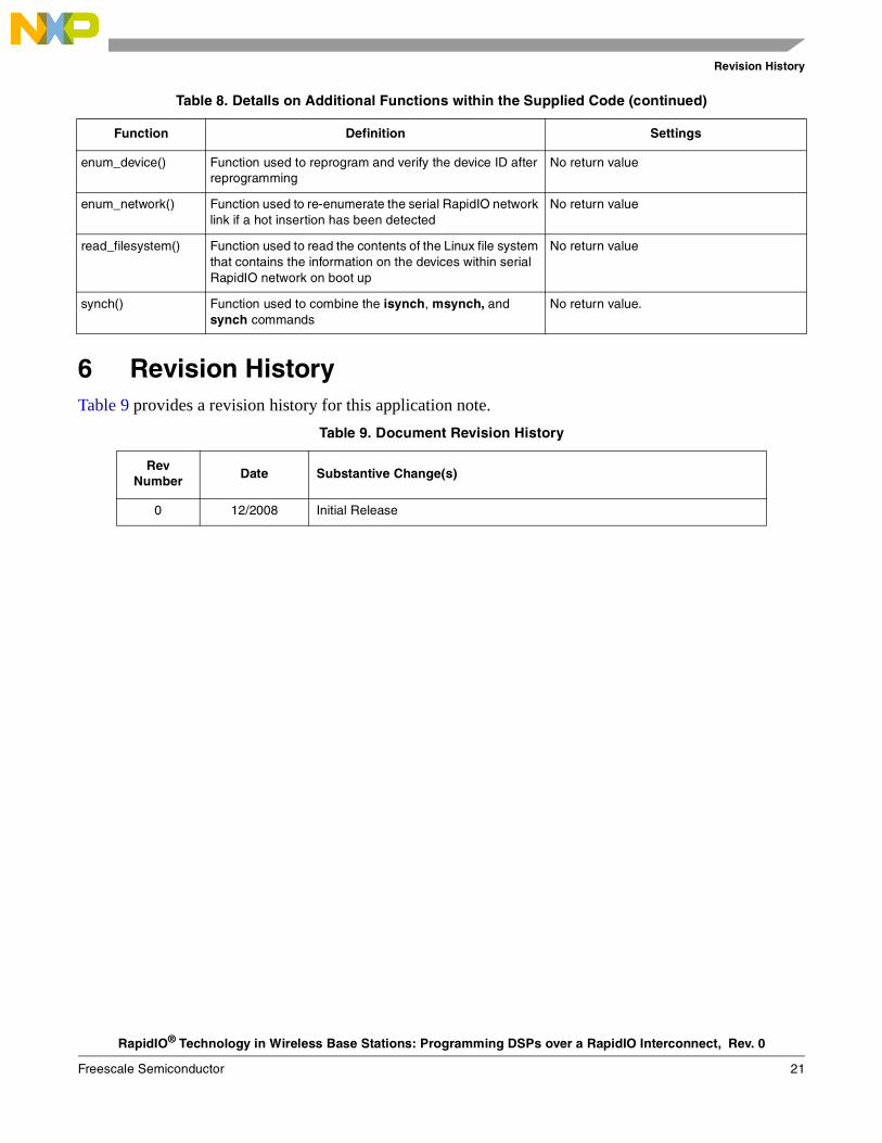
6 Revision HistoryTable 9 provides a revision history for this application note.
enum_device() Function used to reprogram and verify the device ID after reprogramming
No return value
enum_network() Function used to re-enumerate the serial RapidIO network link if a hot insertion has been detected
No return value
read_filesystem() Function used to read the contents of the Linux file system that contains the information on the devices within serial RapidIO network on boot up
No return value
synch() Function used to combine the isynch, msynch, and synch commands
No return value.
Table 9. Document Revision History
Rev Number Date Substantive Change(s)
0 12/2008 Initial Release
Table 8. DetaIls on Additional Functions within the Supplied Code (continued)
Function Definition Settings

RapidIO® Technology in Wireless Base Stations: Programming DSPs over a RapidIO Interconnect, Rev. 0
22 Freescale Semiconductor
Revision History
THIS PAGE INTENTIONALLY LEFT BLANK

RapidIO® Technology in Wireless Base Stations: Programming DSPs over a RapidIO Interconnect, Rev. 0
Freescale Semiconductor 23
Revision History
THIS PAGE INTENTIONALLY LEFT BLANK
Document Number: AN3661Rev. 01/2009
Information in this document is provided solely to enable system and software
implementers to use Freescale Semiconductor products. There are no express or
implied copyright licenses granted hereunder to design or fabricate any integrated
circuits or integrated circuits based on the information in this document.
Freescale Semiconductor reserves the right to make changes without further notice to
any products herein. Freescale Semiconductor makes no warranty, representation or
guarantee regarding the suitability of its products for any particular purpose, nor does
Freescale Semiconductor assume any liability arising out of the application or use of
any product or circuit, and specifically disclaims any and all liability, including without
limitation consequential or incidental damages. “Typical” parameters which may be
provided in Freescale Semiconductor data sheets and/or specifications can and do
vary in different applications and actual performance may vary over time. All operating
parameters, including “Typicals” must be validated for each customer application by
customer’s technical experts. Freescale Semiconductor does not convey any license
under its patent rights nor the rights of others. Freescale Semiconductor products are
not designed, intended, or authorized for use as components in systems intended for
surgical implant into the body, or other applications intended to support or sustain life,
or for any other application in which the failure of the Freescale Semiconductor product
could create a situation where personal injury or death may occur. Should Buyer
purchase or use Freescale Semiconductor products for any such unintended or
unauthorized application, Buyer shall indemnify and hold Freescale Semiconductor
and its officers, employees, subsidiaries, affiliates, and distributors harmless against all
claims, costs, damages, and expenses, and reasonable attorney fees arising out of,
directly or indirectly, any claim of personal injury or death associated with such
unintended or unauthorized use, even if such claim alleges that Freescale
Semiconductor was negligent regarding the design or manufacture of the part.
How to Reach Us:
Home Page: www.freescale.com
Web Support: http://www.freescale.com/support
USA/Europe or Locations Not Listed: Freescale Semiconductor, Inc.Technical Information Center, EL5162100 East Elliot Road Tempe, Arizona 85284 1-800-521-6274 or+1-480-768-2130www.freescale.com/support
Europe, Middle East, and Africa:Freescale Halbleiter Deutschland GmbHTechnical Information CenterSchatzbogen 781829 Muenchen, Germany+44 1296 380 456 (English) +46 8 52200080 (English)+49 89 92103 559 (German)+33 1 69 35 48 48 (French) www.freescale.com/support
Japan: Freescale Semiconductor Japan Ltd. HeadquartersARCO Tower 15F1-8-1, Shimo-Meguro, Meguro-ku Tokyo 153-0064Japan 0120 191014 or+81 3 5437 [email protected]
Asia/Pacific: Freescale Semiconductor China Ltd. Exchange Building 23FNo. 118 Jianguo RoadChaoyang DistrictBeijing 100022China+86 10 5879 [email protected]
For Literature Requests Only:Freescale Semiconductor
Literature Distribution Center P.O. Box 5405Denver, Colorado 80217 1-800 441-2447 or+1-303-675-2140Fax: +1-303-675-2150LDCForFreescaleSemiconductor
@hibbertgroup.com
Freescale, the Freescale logo, and StarCore and the Freescale logo are trademarks or registered trademarks of Freescale Semiconductor, Inc. in the U.S. and other countries. All other product or service names are the property of their respective owners. The Power Architecture and Power.org word marks and the Power and Power.org logos and related marks are trademarks and service marks licensed by Power.org. RapidIO is a registered trademark of the RapidIO Trade Association.
© Freescale Semiconductor, Inc., 2009. All rights reserved.