Embed Size (px)
Citation preview

RAPID III RFP NNG10207304R
ATTACHMENT E
RAPID III
MISSION ASSURANCE REQUIREMENTS
(MAR)
MISSION CLASS: D
November 2, 2009
Page 1 of 126
RAPID III RFP NNG10207304R
Rapid III MARNovember 2, 2009
Signature Page
Prepared by:
Original Signed by: __________________________ David BogartChief Safety and Mission Assurance Officer, RSDONASA/GSFC Code 323.0
11-02-09 ____________Date
Reviewed by:
Original Signed by: __________________________ Michael HagopianSenior AETD Engineer NASA/GSFC Code 500.0
11-02-09 ____________Date
Approved by:
Page 2 of 126
RAPID III RFP NNG10207304R
Original Signed by: __________________________ Gregory SmithChief, RSDONASA/GSFC Code 401.1
11-02-09 ____________Date
Page 3 of 126
RAPID III RFP NNG10207304R
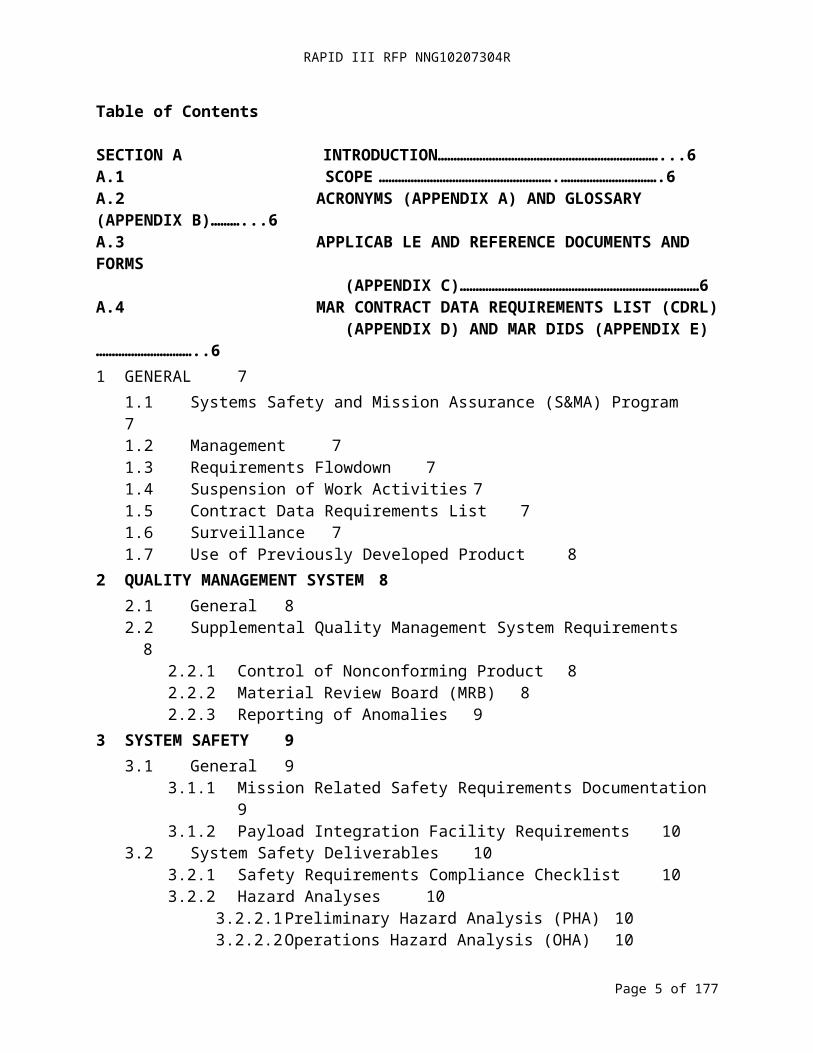
Table of Contents
SECTION A INTRODUCTION……………………………………………………………...6A.1 SCOPE ……………………………………………….………………………….6A.2 ACRONYMS (APPENDIX A) AND GLOSSARY (APPENDIX B)………...6 A.3 APPLICAB LE AND REFERENCE DOCUMENTS AND FORMS (APPENDIX C)…………………………………………………………………6A.4 MAR CONTRACT DATA REQUIREMENTS LIST (CDRL) (APPENDIX D) AND MAR DIDS (APPENDIX E)…………………………..61 GENERAL 7
1.1 Systems Safety and Mission Assurance (S&MA) Program 71.2 Management 71.3 Requirements Flowdown 71.4 Suspension of Work Activities 71.5 Contract Data Requirements List 71.6 Surveillance 71.7 Use of Previously Developed Product 8
2 QUALITY MANAGEMENT SYSTEM 82.1 General 82.2 Supplemental Quality Management System Requirements 8
2.2.1 Control of Nonconforming Product 82.2.2 Material Review Board (MRB) 82.2.3 Reporting of Anomalies 9
3 SYSTEM SAFETY 93.1 General 9
3.1.1 Mission Related Safety Requirements Documentation 93.1.2 Payload Integration Facility Requirements 10
3.2 System Safety Deliverables 103.2.1 Safety Requirements Compliance Checklist 103.2.2 Hazard Analyses 10
3.2.2.1 Preliminary Hazard Analysis (PHA) 103.2.2.2 Operations Hazard Analysis (OHA) 103.2.2.3 Operating and Support Hazard Analysis (O&SHA) 113.2.2.4 Software Safety Analysis 11
3.2.3 Missile System Pre-Launch Safety Package (MSPSP) 113.2.4 Verification Tracking Log 113.2.5 Safety Waivers 113.2.6 Orbital Debris Assessment 113.2.7 Mishap Reporting and Investigation 113.2.8 Range Safety Forms 11
4 PROBABILITY RISK ANALYSIS AND RELIABILITY 124.1 Probabilistic Risk Assessment (PRA) and Reliability Program Plan 124.2 PRA 12
Page 4 of 126
RAPID III RFP NNG10207304R
4.3 Failure Modes and Effects Analysis (FMEA) and Critical Items List (CIL)12
4.4 Fault Tree Analysis 134.5 Reserved 134.6 Reserved 134.7 Reserved 134.8 Reserved 134.9 Trend Analysis 134.10 Analysis of Test Results 144.11 Limited Life Items 14
5 SOFTWARE ASSURANCE (FLIGHT AND GROUND SEGMENTS) 145.1 Applicable Requirements 145.2 Software Quality Assurance 145.3 Verification and Validation 145.4 Reviews 145.5 Software Configuration Management 155.6 Government Furnished Equipment (GFE), Existing, and Purchased Software
155.7 Version Description Documents (VDD) 155.8 Surveillance of Software Development 15
6 GROUND SYSTEMS AND EQUIPMENT 156.1 General 156.2 Reserved 15
7 RISK MANAGEMENT 167.1 General 167.2 Risk List 16
8 RESERVED 169 SYSTEM PERFORMANCE VERIFICATION 16
9.1 System Performance Verification Program Plan 169.2 Environmental Verification Plan 16
9.2.1 Electrical Function and Performance - Performance Operating Time and Failure-Free Performance Testing 16
9.2.2 Structural and Mechanical Testing 179.2.2.1 Unit Level Vibration and Loads Testing 179.2.2.2 Observatory Testing 17
9.2.3 EMC/EMI Testing 189.2.4 Thermal Vacuum Testing 189.2.5 Thermal Balance Testing18
9.3 System Performance Verification Matrix 189.4 Environmental Test Matrix 189.5 Verification Reports 199.6 System Performance Verification Report 19
10 WORKMANSHIP 1910.1 General 19
Page 5 of 126
RAPID III RFP NNG10207304R
10.2 Design and Process Qualification 1910.3 Electrostatic Discharge Control (ESD) 20
11 ELECTRICAL, ELECTRONIC, AND ELECTROMECHANICAL (EEE) PARTS20
11.1 General 2011.2 Parts Control Board 2011.3 EEE Parts Lists 20
11.3.1 Project Approved Parts List (PAPL) 2011.3.2 As-designed Parts List (ADPL) 2011.3.3 As-built Parts List (ABPL) 20
12 MATERIALS AND PROCESSES 2112.1 General 2112.2 Life Test Plan for Lubricated Mechanisms 2112.3 Materials Usage Agreement (MUA) 2112.4 Materials Identification and Usage List (MIUL) 2112.5 Nondestructive Evaluation (NDE) Plan 2112.6 Printed Wiring Board (PWB) Test Coupons 2112.7 Lead-free and Tin Whisker Control Plan 21
13 CONTAMINATION CONTROL 2213.1 Contamination Control Plan 22
14 METROLOGY AND CALIBRATION 2214.1 Metrology and Calibration Program 2214.2 Use of Non-calibrated Instruments 22
15 GOVERNMENT-INDUSTRY DATA EXCHANGE PROGRAM (GIDEP) ALERTS AND PROBLEM ADVISORIES 2215.1 GIDEP2215.2 Reviews 2215.3 Actions 2215.4 Reporting 22
16 END ITEM ACCEPTANCE DATA PACKAGE 2316.1 General 23
17 RULES FOR THE DESIGN, DEVELOPMENT, VERIFICATION, AND OPERATION OF FLIGHT SYSTEMS 2317.1 General 23
APPENDIX A. ACRONYMS 33APPENDIX B. GLOSSARY OF TERMS 36APPENDIX C. APPLICABLE AND REFERENCE DOCUMENTS AND FORMS LISTS
43APPENDIX D. MAR CONTRACT DATA REQUIREMENTS LIST (CDRL) 52Appendix E. MAR Data Item Descriptions (DIDs) 58
Page 6 of 126

RAPID III RFP NNG10207304R
Page 7 of 126

RAPID III RFP NNG10207304R
SECTION A INTRODUCTION
A.1 SCOPE
This document describes the contract baseline safety and mission assurance requirements for the spacecraft development and related services under the National Aeronautics and Space Administration (NASA), Goddard Space Flight Center (GSFC), Rapid III Spacecraft Acquisition (RSA) Contract. These requirements are defined as “Class D” (Reference NASA Procedural Requirement NPR 8705.4). These requirements and the mission class may be modified to meet the mission specific needs of Government projects utilizing this contract. The specific requirements on each mission shall be as defined in the mission specific delivery order (DO).
A.2 ACRONYMS (APPENDIX A) AND GLOSSARY (APPENDIX B)
A listing defining the acronyms used throughout this Mission Assurance Requirements (MAR) document and its Appendices are located in Appendix A. Additionally, a glossary defining specific terms used throughout the MAR and its appendices is located in Appendix B.
A.3 APPLICABLE AND REFERENCE DOCUMENTS AND FORMS (APPENDIX C)
A table of the applicable and reference documents and forms referenced throughout this MAR and its Appendices is located in Appendix C. The table includes each document’s or forms name; document number, revision level, and date; MAR sections or data item descriptions (DIDs) that call-out the document or form; and the document’s or form’s sources (hyperlinks or website locations); plus any applicable notes to the user. Applicable documents contain requirements associated with the MAR and apply directly to the performance required. Reference documents and forms contain information related to the work required by the MAR.
A.4 MAR CONTRACT DATA REQUIREMENTS LIST (CDRL) (APPENDIX D) AND MAR DIDS (APPENDIX E)
The MAR Contract Data Requirements List (CDRL) is included in Appendix D. Appendix E includes the Data Item Descriptions (DIDs) identified in the MAR.
Page 8 of 126
RAPID III RFP NNG10207304R
1 GENERAL
1.1 SYSTEMS SAFETY AND MISSION ASSURANCE (S&MA) PROGRAM
The Contractor shall prepare, document, and implement a Mission Assurance Implementation Plan (MAIP) (DID MA 1-1). The MAIP shall cover:
a. All flight hardware and software that is designed, built, or provided by the Contractor and its subcontractors or furnished by the Government, from project initiation through launch and mission operations.
b. The ground support equipment that interfaces with flight equipment to the extent necessary to assure the integrity and safety of flight items (includes electrical, mechanical, software, and test facilities).
1.2 MANAGEMENT
The Contractor shall designate a manager for assurance activities. The manager shall have direct access to management that is independent of project management and functional freedom and authority to interact with all elements of the project.
1.3 REQUIREMENTS FLOWDOWN
The Contractor shall apply the applicable portions of their MAIP to its subcontractors.
1.4 SUSPENSION OF WORK ACTIVITIES
The Contractor shall direct the suspension of any work activity that presents a present hazard, imminent danger, or future hazard to personnel, property, or mission operations resulting from unsafe acts or conditions that are identified by inspection, test, or analysis.
1.5 CONTRACT DATA REQUIREMENTS LIST
The Contract Data Requirements List (CDRL) (MAR Appendix D) identifies data items for delivery to the Government required by the MAR. The Contractor shall deliver each data item in accordance with the requirements of the Rapid III CDRL Instructions, the MAR CDRL table and each associated Data Item Description (DID). MAR CDRL items are numbered with the prefix MA for “mission assurance”. Unless otherwise specified in the DO and with the exception of the Printed Wiring Board Coupons (required by DID MA 12-6), all deliverables shall be provided to the Government per Section 1.4 and 1.5 of the Rapid III CDRL.
1.6 SURVEILLANCE
The Contractor shall grant access for Government assurance representatives to conduct an audit, assessment, or survey upon notice. The Contractor shall supply documents, records, equipment, and a work area within the Contractor’s facilities.
Page 9 of 126
RAPID III RFP NNG10207304R
1.7 USE OF PREVIOUSLY DEVELOPED PRODUCT
The Contractor shall document the compliance of previously developed product with the requirements of the MAIP (DID MA 1-2).
2 QUALITY MANAGEMENT SYSTEM
2.1 GENERAL
The Contractor shall have a Quality Management System that is compliant with the requirements of Society of Automotive Engineers SAE AS9100, Quality Systems - Aerospace - Model for Quality Assurance in Design, Development, Production, Installation and Servicing, or American National Standards Institute (ANSI)/International Organization for Standardization (ISO)/American Society for Quality (ASQ) Q9001, Quality Management Systems – Requirements, or equivalent. The Contractor shall provide a copy of the Quality Manual to the Government (DID MA 2-1).
2.2 SUPPLEMENTAL QUALITY MANAGEMENT SYSTEM REQUIREMENTS
2.2.1 Control of Nonconforming Product
Control of Nonconforming Product – The Contractor shall have a documented closed loop system for identifying, reporting, and correcting nonconformances. The system shall ensure that positive corrective action is implemented to preclude recurrence, that objective evidence is collected, and that the adequacy of corrective action is determined by audit or test.
2.2.2 Material Review Board (MRB)
The Contractor shall have a documented process for the establishment and operation of an MRB to process nonconformances, including the definitions of major and minor nonconformances. The Contractor shall appoint an MRB chairperson who is responsible for implementing the MRB process and for appointing functional and project representatives as MRB members. The MRB membership shall include a voting member representing the Government Project Office’s S&MA Officer. Government participation and voting in MRBs will be for major non-conformances. The contractor shall make available for Government review all MRB actions (i.e., minor non-conformances) at the time of disposition. Government will ensure participation in MRB activities within a five (5) working day timeframe to avoid possible schedule impacts. The Contractor shall inform the Government of MRB actions (DID MA 2-2).
The MRB shall use the following disposition actions:
a. Scrap — the product is not usable.b. Re-work — the product shall be re-worked to conform to requirements.c. Return to supplier — the product shall be returned to the supplier.d. Repair — the product shall be repaired using a repair process approved by the MRB. e. Use-as-is — the product shall be used as is, processed as Major MRB.
Page 10 of 126
RAPID III RFP NNG10207304R
The Contractor shall submit a waiver to requirements for government approval for a use-as-is disposition involving a major nonconformance (DID MA 2-3).
2.2.3 Reporting of Anomalies
The Contractor shall have a documented process for reporting anomalies. The Contractor shall report hardware anomalies beginning with the first application of power at the component level, software anomalies beginning with first use of the flight build software, and mechanical system anomalies beginning with the first operation (DID MA 2-4). The Anomaly Review Board (ARB) membership shall include a voting member representing the Government Project Office’s S&MA Officer. The Government S&MA representative (or a designated alternate) will be present at all ARB meetings, with approval/disapproval authority of proposed actions.
3 SYSTEM SAFETY
3.1 GENERAL
The Contractor shall document and implement a system safety program in accordance with NPR 8715.3, NASA General Safety Program Requirements; NPR 8715.7, Expendable Launch Vehicle Payload Safety Program; launch service provider requirements; and launch range safety requirements (DID MA 3-1).
Specific safety requirements include the following:
a. The Contractor shall incorporate three independent inhibits in the design (dual fault tolerant) if a system failure may lead to a catastrophic hazard. A catastrophic hazard is defined as a condition that may cause death or a permanent disabling injury or the destruction of a major system or facility on the ground or of the vehicle during the mission.
b. The Contractor shall incorporate two independent inhibits in the design (single fault tolerant) if a system failure may lead to a critical hazard. A critical hazard is defined as a condition that may cause a severe injury or occupational illness to personnel or major property damage to facilities, systems, or flight hardware.
c. The Contractor shall adhere to specific detailed safety requirements, including compliance verification that shall be met for design elements with hazards that cannot be controlled by failure tolerance. These design elements, e.g., structures and pressure vessels, are called "Design for Minimum Risk" areas.
3.1.1 Mission Related Safety Requirements Documentation
The Contractor shall implement launch range requirements. The Contractor shall adhere to the most stringent applicable safety requirement in the event of conflicting requirements.
Page 11 of 126
RAPID III RFP NNG10207304R
a. Air Force Space Command Manual (AFSPCMAN) 91-710, Range Safety User Requirements Manual
b. Kennedy NASA Procedural Requirements (KNPR) 8715.3, KSC Safety Practices Procedural Requirements
c. NPR 8715.7, Expendable Launch Vehicle Payload Safety Programd. Facility-specific Safety Requirements, as applicablee. NASA Safety Standard (NSS) 1740.12, Safety Standard for Explosives, Propellants, and
Pyrotechnicsf. NSS 1740.14, Guidelines and Assessment Procedures for Limiting Orbital Debris
3.1.2 Payload Integration Facility Requirements
The Contractor shall document and implement procedures that comply with applicable installation safety requirements when performing payload integration and test activities and pre-launch activities at the launch site (DID MA 3-2). The Contractor shall provide safety support for hazardous operations at the launch site.
For work to be performed at GSFC, the Contractor shall meet the requirements of 500-PG-8715.1.2, the Applied Engineering and Technology Directorate (AETD) Safety Manual.
3.2 SYSTEM SAFETY DELIVERABLES
3.2.1 Safety Requirements Compliance Checklist
The Contractor shall prepare a Safety Requirements Compliance Checklist to demonstrate that the spacecraft is in compliance with range safety requirements (DID MA 3-3). The Contractor shall document noncompliances to safety requirements in waivers and submit them for approval (Reference MAR Section 3.2.5).
3.2.2 Hazard Analyses
3.2.2.1 Preliminary Hazard Analysis (PHA)
The Contractor shall document PHA (DID MA 3-4).
3.2.2.2 Operations Hazard Analysis (OHA)
The Contractor shall document OHA and a Hazard Tracking Log to demonstrate that hardware operations, test equipment operations, and integration and test (I&T) activities comply with facility safety requirements and that hazards associated with those activities are mitigated to an acceptable level of risk (DID MA 3-5). The Contractor shall maintain and update the Hazard Tracking Log during I&T activities to track open issues.
The Contractor shall meet the safety requirements of NASA-Standard NASA-STD-8719.9, Standard for Lifting Devices and Equipment, when NASA-owned or NASA contractor-supplied equipment is used in support of NASA operations at NASA installations.
Page 12 of 126

RAPID III RFP NNG10207304R
The Contractor shall meet the safety requirements of NASA-STD-8719.9 or contractor equivalent when performing NASA work at contractor facilities.
3.2.2.3 Operating and Support Hazard Analysis (O&SHA)
The Contractor shall document O&SHA to evaluate activities for hazards introduced during pre-launch processing and to evaluate the adequacy of operational and support procedures used to eliminate, control, or mitigate hazards (DID MA 3-6).
3.2.2.4 Software Safety Analysis
The Contractor shall perform Software Safety Analyses to demonstrate that adequate inhibits and controls are incorporated to eliminate or mitigate hazards associated with software.
3.2.3 Missile System Pre-Launch Safety Package (MSPSP)
The Contractor shall prepare an integrated MSPSP (DID MA 3-7).
3.2.4 Verification Tracking Log
The Contractor shall prepare, implement, and maintain a Verification Tracking Log (VTL) (DID MA 3-8).
3.2.5 Safety Waivers
The Contractor shall submit Safety Waivers or Deviations for variations to the applicable safety requirements (DID MA 3-9).
3.2.6 Orbital Debris Assessment
The Contractor shall prepare an Orbital Debris Assessment (ODA) (DID MA 3-10).
3.2.7 Mishap Reporting and Investigation
The Contractor shall prepare a contingency plan (DID MA 3-11). The Contractor shall report mishaps, incidents, and close calls per NPR 8621.1, NASA Procedures and Guidelines for Mishap Reporting, Investigating, and Recordkeeping.
3.2.8 Range Safety Forms
The Contractor shall prepare the following, as required, by their spacecraft design and/or the Project Office:
a. Kennedy Space Center (KSC) Form Kennedy Technical Instruction (KTI) 5212, Material Selection List for Plastic Films, Foams, and Adhesive Tapes (DID MA 3-12);
b. KSC Form 16-450 NS, Radiation Training & Experience Summary (Non-Ionizing Radiation) (DID MA 3-13);
Page 13 of 126

RAPID III RFP NNG10207304R
c. KSC Form 16-294 NS, Radiation Training & Experience Summary (Ionizing Radiation) (DID MA 3-13);
d. KSC Form 16-447, Laser Device Use Request/Authorization (DID MA 3-13);e. KSC Form 16-451 NS, Radiofrequency/Microwave System Use
Request/Authorization (DID MA 3-13);f. KSC Form 16-295 NS, Radiation Use Request/Authorization (Radioactive Materials)
(DID MA 3-13);g. KSC Form 26-551 V2, Process Waste Questionnaire (DID MA 3-14); andh. Air Force (AF) Form 813, Request for Environmental Impact Analysis (DID MA 3-
15).
4 PROBABILITY RISK ANALYSIS AND RELIABILITY
4.1 PROBABILISTIC RISK ASSESSMENT (PRA) AND RELIABILITY PROGRAM PLAN
The Contractor shall prepare and implement a PRA and Reliability Program Plan using both qualitative and quantitative techniques to support decisions regarding safety throughout system development. The Contractor shall present the implementation of these plans and related activities at milestone reviews beginning with the System Requirements Review (DID MA 4-1).
4.2 PRA
The Contractor shall perform a simplified scope PRA on safety critical items per NPR 8705.5, Probabilistic Risk Assessment (PRA) Procedures for NASA Programs and Projects, and NPR 8715.3, NASA General Safety Program Requirements, (DID MA 4-2).
4.3 FAILURE MODES AND EFFECTS ANALYSIS (FMEA) AND CRITICAL ITEMS LIST (CIL)
The Contractor shall perform a FMEA and prepare and maintain a CIL for severity categories 1, 1R, and 1S per Table 4.1 (DID MA 4-3). The Contractor shall analyze single point failure modes resulting in severity categories 1, 1R, and 1S to determine the root cause, corresponding mitigation actions, and retention rationale. The Contractor shall address flight hardware and software that is designed, built, or provided by its organization or subcontractors, from project initiation through launch and mission operations. The Contractor shall address the ground system that interfaces with flight equipment to the extent necessary to assure the integrity and safety of flight items. The Contractor shall identify and address safety critical software, as defined in NASA-STD-8719.13, Software Safety Standard.
Page 14 of 126
RAPID III RFP NNG10207304R
Table 4-1 Severity Categories
Category Severity Description1 Catastrophic/
CriticalCatastrophic failure modes are those that may cause death or a permanent disabling injury or the destruction of a major system or facility on the ground or of the vehicle during the mission. Critical failure modes those that may cause a severe injury or occupational illness to personnel or major property damage to facilities, systems, or flight hardware.
1R Catastrophic/ Critical
Failure modes of identical or equivalent redundant hardware or software elements that could result in Category 1 effects if all failed.
1S Catastrophic/ Critical
Failure in a safety or hazard monitoring system that could cause the system to fail to detect a hazardous condition or fail to operate during such condition and lead to Category 1 consequences.
4.4 FAULT TREE ANALYSIS
The Contractor shall perform quantitative fault tree analyses on safety critical items as part of the PRA for the core spacecraft and performance options (DID MA 4-4). The Contractor shall identify and address safety critical software as defined in NASA-STD-8719.13. The Contractor shall expand the fault tree analyses as part of the PRA to include instruments and spacecraft to instrument integration to the extent defined in the mission specific Delivery Order (DO).
4.5 RESERVED
4.6 RESERVED
4.7 RESERVED
4.8 RESERVED
4.9 TREND ANALYSIS
The Contractor shall prepare and maintain a list of subsystem and components to be assessed and parameters to be monitored as defined in the approved PRA and Reliability Program Plan for safety critical functions only.
The Contractor shall begin trend monitoring, collection, and analysis at component acceptance testing and continue through the system integration and test phases. Trend data shall be provided as part of the End Item Acceptance Data Package (DID MA 16-1).
Page 15 of 126
RAPID III RFP NNG10207304R
4.10 ANALYSIS OF TEST RESULTS
The Contractor shall document the analysis of test information, trend data, and failure investigations with respect to reliability and report the results as defined in the approved PRA and Reliability Program Plan for safety critical functions only.
4.11 LIMITED LIFE ITEMS
The Contractor shall prepare and implement a plan to identify and manage limited life items for safety critical functions only (DID MA 4-5).
5 SOFTWARE ASSURANCE (FLIGHT AND GROUND SEGMENTS)
5.1 APPLICABLE REQUIREMENTS
The Contractor shall comply with the following for software and firmware, hereafter collectively referred to as software:
a. NPR 7150.2, NASA Software Engineering Requirements;b. NASA-STD-8719.13, Software Safety Standard; andc. NASA-STD-8739.8, NASA Standard for Software Assurance.
5.2 SOFTWARE QUALITY ASSURANCE
The Contractor shall prepare and implement a Software Quality Assurance Plan (SQAP) for software, including Government off-the-shelf (GOTS) software, modified off-the-shelf (MOTS) software, and commercial off-the-shelf (COTS) software (DID MA 5-1). The Contractor shall identify the person responsible for directing and managing the software quality assurance program.
5.3 VERIFICATION AND VALIDATION
The Contractor shall prepare and implement a Verification and Validation (V&V) program plan to ensure that the software satisfies functional and performance requirements (DID MA 5-2).
5.4 REVIEWS
The Contractor shall conduct and document periodic reviews, audits, and assessments of the software development process and products. In addition to the reviews specified in Section 8, the Contractor shall provide advance notification to the project office of the following software reviews:
a. Test Readiness Review;b. Acceptance Review; and
Page 16 of 126

RAPID III RFP NNG10207304R
c. Software Safety Program Reviews or system level safety reviews.
5.5 SOFTWARE CONFIGURATION MANAGEMENT
The Contractor shall prepare and implement a Software Configuration Management (SCM) plan (DID MA 5-3).
5.6 GOVERNMENT FURNISHED EQUIPMENT (GFE), EXISTING, AND PURCHASED SOFTWARE
No GFE Software will be provided as part of the Core spacecraft contract. Any GFE software requirements will be addressed as part of the delivery order (DO)
5.7 VERSION DESCRIPTION DOCUMENTS (VDD)
The Contractor shall prepare VDDs that identify and document the version of the computer software configuration items (CSCIs) and other deliverable items that comprise the software build or release, including changes since the last VDD was issued (DID MA 5-4).
5.8 SURVEILLANCE OF SOFTWARE DEVELOPMENT
The Contractor shall provide the following:
a. Access to the software problem reporting system, either through remote means or paper copies;
b. Access to the software documentation (management plans, assurance plans, configuration management plans, design plans);
c. Access to the software review results;d. Access to the corrective actions from process and product audits;e. Notification of engineering peer reviews (e.g., code reviews);f. Access to review action item status and resolution; andg. Software status report (DID MA 5-5).
6 GROUND SYSTEMS AND EQUIPMENT
6.1 GENERAL
The Contractor shall document and implement a ground support equipment program for flight and ground operations products to assure the function and integrity of flight items (DID MA 6-1).
6.2 RESERVED
Page 17 of 126
RAPID III RFP NNG10207304R
7 RISK MANAGEMENT
7.1 GENERAL
The Contractor shall document and implement a risk management plan (DID MA 7-1).
7.2 RISK LIST
The Contractor shall prepare and maintain a risk list (DID MA 7-2).
8 RESERVED
9 SYSTEM PERFORMANCE VERIFICATION
9.1 SYSTEM PERFORMANCE VERIFICATION PROGRAM PLAN
The Contractor shall plan and implement a system performance verification program per the requirements of GSFC-STD-7000, General Environmental Verification Standard (GEVS) for GSFC Flight Programs and Projects, (DID MA 9-1).
9.2 ENVIRONMENTAL VERIFICATION PLAN
The Contractor shall prepare and implement an environmental verification plan (DID MA 9-2). Several requirements within GEVS have been specifically tailored, herein, for the RSDO Rapid III MAR. The environmental verification plan and implementation shall include, but not be limited to, the tailored requirements as identified below.
Section 9.2.1 through Section 9.2.5 provides specific tailoring of selected GEVS requirements for implementation on RSDO spacecraft and observatories.
9.2.1 Electrical Function and Performance - Performance Operating Time and Failure- Free Performance Testing
Electrical function and performance testing shall be performed in accordance with GEVS Section 2.3 with the following clarifications.
One-thousand (1000) hours of operating/power-on time shall be accumulated on all spacecraft flight electronic hardware (and spares, if to be flown), prior to launch.
Page 18 of 126

RAPID III RFP NNG10207304R
At the conclusion of the performance verification program, the observatory shall have demonstrated failure-free performance testing for at least the last 350 hours of operation.
At the conclusion of the observatory thermal-vacuum test, 200 hours of failure-free operation (100 at hot dwell and 100 at cold dwell) shall also have been demonstrated.
9.2.2 Structural and Mechanical Testing
Structural and Mechanical testing shall be performed in accordance with GEVS Section 2.4 with the following clarifications.
A test verified model of the core spacecraft shall be developed.
The observatory (core spacecraft plus instrument(s)) shall be modeled and the results provided to the project office to perform the coupled loads (launch vehicle plus observatory) analyses for mission critical events required by the launch vehicle. Three (3) versions (for PDR, CDR, and final loads verification) of the model shall be provided. Refer to GEVS Section 2.4.1.1.1.
For all elements that are to be qualified by analysis, positive strength margins on yield shall be shown to exist at stresses equal to 2.0 times those induced by the limit loads, and positive margins on ultimate shall be shown to exist at stresses equal to 2.6 times those induced by the limit loads. Structural elements fabricated from composite materials or beryllium, and bonded joints shall not be qualified by analysis alone. Refer to GEVS Table 2.2-3 for Flight Hardware Design/Analysis Factors of Safety Applied to Limit Loads.
Analysis shall also verify adequate dynamic clearances between the observatory and launch vehicle and between members within the observatory for all significant ground test and flight conditions. Refer to GEVS section 2.4.1.1.2
9.2.2.1 Unit Level Vibration and Loads Testing
All flight units shall be subjected to random vibration, swept sine vibration, and sine burst testing in 3 axes. GEVS Protoflight or acceptance levels, as defined in GEVS, shall be used as appropriate.
9.2.2.2 Observatory Testing
Observatory shall be subjected to 3 axis random and swept sine vibration tests. A first of a kind observatory (bus plus instrument(s)) shall be subjected to protoflight levels. The upper frequency of the sine test shall be, as a minimum, 50 Hz but shall be increased if required to envelop launch vehicle events or requirements.
The observatory shall be subjected to an acoustics test.
Note: For all unit and observatory tests, the hardware shall be performed in the launch configuration (i.e. if a component is powered on during launch, it shall be powered on during these tests).
Page 19 of 126
RAPID III RFP NNG10207304R
Testing for all self-induced shocks shall be performed at the subsystem (or unit level) by actuation of the shock-producing devices. Protoflight qualification requires two actuations and acceptance one.
9.2.3 EMC/EMI Testing
EMI/EMC testing shall be performed in accordance with GEVS Section 2.5 with the following clarification.
All flight units, including spares, shall be EMI/EMC tested at the component/unit level of assembly. Refer to Table 2.5.1 of GEVS. In addition, every observatory shall be tested for radiated susceptibility (paragraph 2.5.3.2.a of GEVS).
9.2.4 Thermal Vacuum Testing
Thermal-vacuum testing shall be performed in accordance with GEVS Section 2.6 with the following clarifications.
All units, including spares, shall be subjected to 12 thermal-vacuum cycles. Testing at the observatory level may be included as part of the 12 cycles. Temperatures and dwell durations shall be per GEVS Section 2.6. Power shall be applied and performance monitored during the tests.
Four (4) thermal-vacuum cycles are required at the observatory level. The dwell times shall be 24 hours or the time required to complete CPT’s whichever is longer. Temperatures are to protoflight or acceptance levels as appropriate. During this test, redundant hardware shall be tested. The 4 cycles are also intended to test repeatability of performance. Hot- and cold-turn-on, and recovery from safe-hold shall also be demonstrated.
9.2.5 Thermal Balance Testing
The adequacy of the thermal design and the capability of the thermal control system shall be verified under simulated on-orbit worst case hot and worst case cold environments, and at least one other mission specific condition. Refer to GEVS section 2.6.3 for further discussion of methods and samples of margins that shall be verified during the thermal balance tests.
9.3 SYSTEM PERFORMANCE VERIFICATION MATRIX
The Contractor shall prepare and maintain a system performance verification matrix (DID MA 9-3).
9.4 ENVIRONMENTAL TEST MATRIX
The Contractor shall prepare and maintain an environmental test matrix (DID MA 9-4).
Page 20 of 126

RAPID III RFP NNG10207304R
9.5 VERIFICATION REPORTS
The Contractor shall prepare and submit verification reports (DID MA 9-5).
9.6 SYSTEM PERFORMANCE VERIFICATION REPORT
The Contractor shall prepare and submit system performance reports (DID MA 9-6).
10 WORKMANSHIP
10.1 GENERAL
The Contractor shall implement a workmanship program to assure that electronic packaging technologies, processes, and workmanship meet mission objectives for quality and reliability per the requirements of the following standards:
a. NASA-STD-8739.1, Workmanship Standard for Staking and Conformal Coating of Printed Wiring Boards and Electronic Assemblies
b. NASA-STD-8739.2, Workmanship Standard for Surface Mount Technologyc. NASA-STD-8739.3, Soldered Electrical Connectionsd. NASA-STD-8739.4, Crimping, Interconnecting Cables, Harnesses, and Wiringe. NASA-STD-8739.5, Fiber Optic Terminations, Cable Assemblies, and Installationf. IPC-2221, Generic Standard on Printed Board Designg. IPC-2222, Sectional Design Standard for Rigid Organic Printed Boardsh. IPC-2223, Sectional Design Standard for Flexible Printed Boardsi. IPC-2225, Sectional Design Standard for Organic Multichip Modules (MCM-L) and
MCM-L Assembliesj. IPC A-600, Acceptability of Printed Boards (Class 3 Requirements)k. IPC-6011, Generic Performance Specification for Printed Boards (Class 3 Requirements)l. IPC-6012, Qualification and Performance Specification for Rigid Printed Boards (Class
3/A Requirements)m. IPC-6013, Qualification and Performance Specification for Flexible Printed Boards
(Class 3 Requirements)n. IPC-6015, Qualification and Performance Specification for Organic Multichip Module
(MCM-L) Mounting and Interconnecting Structureso. IPC-6018, Microwave End Product Board Inspection and Testp. ANSI/Electrostatic Discharge Association (ESD) S20.20, For the Development of an
Electrostatic Discharge Control Program for Protection of Electrical and Electronic Parts, Assemblies and Equipment (Excluding Electrically Initiated Explosive Devices)
10.2 DESIGN AND PROCESS QUALIFICATION
The Contractor shall qualify designs and processes that are not covered by the above standards.
Page 21 of 126
RAPID III RFP NNG10207304R
10.3 ELECTROSTATIC DISCHARGE CONTROL (ESD)
The Contractor shall prepare and implement an ESD control program that conforms to the requirements of ANSI/ESD S20.20 (DID MA 10-1).
11 ELECTRICAL, ELECTRONIC, AND ELECTROMECHANICAL (EEE) PARTS
11.1 GENERAL
The Contractor shall plan and implement a parts control program (PCP) plan per the Level 3 requirements of GSFC EEE-INST-002, Instructions for EEE Parts Selection, Screening, Qualification, and Derating (DID MA 11-1).
11.2 PARTS CONTROL BOARD
The Contractor shall establish a parts control board (PCB) that is responsible for the planning, management, and coordination of the selection, application, and procurement requirements of EEE parts (DID 11-2). The PCB membership shall include the Government Project Parts Engineer (PPE) as a voting member. The Government PPE (or a designated alternate) will be present at all PCB meetings.
11.3 EEE PARTS LISTS
The Contractor shall develop and maintain EEE parts lists.
11.3.1 Project Approved Parts List (PAPL)
The Contractor shall prepare a list of EEE parts that are approved for use in flight hardware by the PCB (DID MA 11-3).
11.3.2 As-designed Parts List (ADPL)
The Contractor shall prepare a list of EEE parts that are used in the design of flight hardware (DID MA 11-4).
11.3.3 As-built Parts List (ABPL)
The Contractor shall prepare a list of EEE parts that are used in the flight hardware (DID MA 11-5).
Page 22 of 126

RAPID III RFP NNG10207304R
12 MATERIALS AND PROCESSES
12.1 GENERAL
The Contractor shall prepare and implement a materials and processes selection, implementation, and control plan per the requirements of NASA-STD-6016, Standard Materials and Processes Requirement for Spacecraft (DID MA 12-1).
12.2 LIFE TEST PLAN FOR LUBRICATED MECHANISMS
The Contractor shall prepare and implement a life test plan for lubricated mechanisms (DID MA 12-2).
12.3 MATERIALS USAGE AGREEMENT (MUA)
The Contractor shall prepare materials usage agreements (DID MA 12-3).
12.4 MATERIALS IDENTIFICATION AND USAGE LIST (MIUL)
The Contractor shall prepare a materials identification and usage list (DID MA 12-4). The Materials and Processes Control Board (MPCB) membership shall include the Government Project’s Materials and Processes Engineer (MPE) as a voting member. The Government MPE (or a designated alternate) will be present at all MPCB meetings.
12.5 NONDESTRUCTIVE EVALUATION (NDE) PLAN
The Contractor shall prepare and implement a nondestructive evaluation plan for the procedures and specifications used in the inspection of materials (DID MA 12-5).
12.6 PRINTED WIRING BOARD (PWB) TEST COUPONS
The Contractor shall provide PWB test coupons to the GSFC or to a GSFC approved facility for analysis (DID MA 12-6). The Contractor shall not use printed wiring boards until the analyses results are received.
12.7 LEAD-FREE AND TIN WHISKER CONTROL PLAN
The Contractor shall meet the requirements of Government Electronics Information Technology Association (GEIA)-STD-0005-1, Performance Standard for Aerospace and High Performance Electronics Systems Containing Lead-free Solder, and GEIA-STD-0005-2, Standard for Mitigating the Effects of Tin Whiskers in Aerospace and High Performance Electronic Systems, for solders and surface finishes that are less than three percent (3%) lead by weight.
Page 23 of 126
RAPID III RFP NNG10207304R
13 CONTAMINATION CONTROL
13.1 CONTAMINATION CONTROL PLAN
The Contractor shall prepare and implement a contamination control program (DID MA 13-1).
14 METROLOGY AND CALIBRATION
14.1 METROLOGY AND CALIBRATION PROGRAM
The Contractor shall plan and implement a documented metrology and calibration program. The Contractor shall comply with ANSI/NCSL Z540.3:2006, Requirements for the Calibration of Measuring and Test Equipment.
14.2 USE OF NON-CALIBRATED INSTRUMENTS
The Contractor shall limit the use of non-calibrated instruments to applications where substantiated accuracy is not required and for indication-only purposes in non-hazardous, non-critical applications.
15 GOVERNMENT-INDUSTRY DATA EXCHANGE PROGRAM (GIDEP) ALERTS AND PROBLEM ADVISORIES
15.1 GIDEP
The Contractor shall participate in GIDEP per the GIDEP Operations Manual, S0300-BT-PRO-010, and, GIDEP Requirements Guide, S0300-BU-GYD-010.
15.2 REVIEWS
The Contractor shall review the following, hereafter referred to collectively as Alerts, for affects on NASA products: GIDEP Alerts; GIDEP SAFE-ALERTS; GIDEP Problem Advisories; GIDEP Agency Action Notices; NASA Advisories and component issues as distributed by the project office.
15.3 ACTIONS
The Contractor shall take action to eliminate or mitigate the effects of Alerts on NASA products.
15.4 REPORTING
The Contractor shall report the results of Alert reviews and actions taken (DID MA 15-1).
Page 24 of 126
RAPID III RFP NNG10207304R
The Contractor shall prepare and submit failure experience data reports per the requirements of S0300-BT-PRO-010 and S0300-BU-GYD-010 whenever failed or nonconforming items that are available to other buyers are discovered.
The Contractor shall report significant EEE parts, materials, and safety problems (DID MA 15-2).
The Contractor shall report the status of NASA products that are affected by Alerts or by significant EEE parts, materials, and safety problems at program milestone reviews and readiness reviews. The Contractor shall include a summary of the review status for EEE parts and materials lists and of actions taken to eliminate or mitigate negative effects.
16 END ITEM ACCEPTANCE DATA PACKAGE
16.1 GENERAL
The Contractor shall prepare, maintain, and submit an end item acceptance data package (DID MA 16-1).
17 RULES FOR THE DESIGN, DEVELOPMENT, VERIFICATION, AND OPERATION OF FLIGHT SYSTEMS
17.1 GENERAL
The following requirements are Gold Rules that have been tailored for the RSDO application. Reference the GSFC-STD-1000, “Rules for the Design, Development, Verification and Operation of Flight Systems”, Rev E for further information pertaining to the calculations of margins, project phase application, etc.
RSDO-GR-1.05, Single Point Failures - Spacecraft single point failures that prevent the ability to fully meet Mission success requirements shall be identified, and the risk associated with each shall be characterized, managed, and tracked.
RSDO-GR-1.06, Resource Margins - Spacecraft related system resource margins shall be evaluated in accordance with GSFC-STD-1000 (Rev E) Table 1.06-1, with margin and contingency/reserve defined in the table, and illustrated in Figures 1.06-1 and 1.06-2. Table 1.06-2 is a schedule of recommended mass contingency or reserve by subsystem.
Page 25 of 126

RAPID III RFP NNG10207304R
RSDO-GR-1.07, End-to-End GN&C Phasing - All GN&C sensors and actuators shall undergo end-to-end phasing/polarity testing after spacecraft integration and shall have flight software mitigations to correct errors efficiently.
RSDO-GR-1.08, End-to-End Testing - System end-to-end testing shall be performed using actual flight hardware and software, wherever practicable, and shall apply from input to instrument(s), through the spacecraft, transmitted to receiving antennas, and through the ground system - reconciled against what is physically achievable before launch, and consistent with associated mission risk.
RSDO-GR-1.09, Test as You Fly - Spacecraft/Observatory level testing shall follow a, "Test as You Fly (TYF) - Fly as You Test" approach, throughout all applicable lifecycles.
RSDO-GR-1.10 RESERVED
RSDO-GR-1.11, Qualification of Heritage Flight Hardware - All spacecraft heritage flight hardware shall be fully qualified and verified for use in its new application. This qualification shall take into consideration necessary design modifications, changes to expected environments, and differences in operational use.
RSDO-GR-1.12, RESERVED
RSDO-GR-1.13, RESERVED
RSDO-GR-1.14, Mission Critical Telemetry and Command Capability - All spacecraft shall be capable of providing continuous telemetry coverage during all mission-critical events. Mission-critical events shall be defined to include separation from the launch vehicle; power-up of major components or subsystems; deployment of mechanisms and/or mission-critical appendages; and all planned propulsive maneuvers required to establish mission orbit and/or achieve safe attitude. After separation from the launch vehicle, all spacecraft shall be capable of providing continuous command coverage during all following mission-critical events.
RSDO-GR-1.15, RESERVED
RSDO-GR-1.16, RESERVED
RSDO-GR-1.17, Safe Hold Mode - All spacecraft shall have a power-positive control mode (Safe Hold) to be entered in spacecraft emergencies. Safe Hold Mode shall have the following characteristics: (1) its safety shall not be compromised by the same credible fault that led to Safe Hold activation; (2) it shall be as simple as practical, employing the minimum hardware set required maintaining a safe attitude; and (3) it shall require minimal ground intervention for safe operation.
RSDO-GR-1.18, RESERVED
Page 26 of 126

RAPID III RFP NNG10207304R
RSDO-GR-1.19, Initial Thruster Firing Limitations - All spacecraft shall provide real-time telemetry and command capability for each initial thruster firings.. If alternate actuators (e.g. reaction wheels) are present, the momentum induced by initial firings shall be within the alternate actuators' capability to execute safe recovery of the spacecraft.
RSDO-GR-1.20, Manifold Joints of Hazardous Propellants - All joints in the propellant manifold between the propellant supply tank and the first isolation valve shall be NDE-verified welds.
RSDO-GR-1.21, Over pressurization Protection in Liquid Propulsion Systems - The propulsion system design and operations shall preclude damage due to pressure surges ("water hammer"). (Note: See also rule 1.28 "Unintended Propellant Vapor Ignition.")
RSDO-GR-1.22, Purging of Residual Test Fluids - Propulsion system design and the assembly & test plans shall preclude entrapment of test fluids that are reactive with wetted material or propellant.
RSDO-GR-1.23, Spacecraft 'OFF' Command - In a redundant Spacecraft with no hardware failures, no single command shall result in Spacecraft "OFF." In a single string Spacecraft, or a redundant Spacecraft with a failure, no single command shall result in Spacecraft "OFF."
RSDO-GR-1.24, Propulsion System Safety Electrical Disconnect - An electrical disconnect "plug" and/or set of restrictive commands shall be provided to preclude inadvertent operation of propulsion system components.
RSDO-GR-1.25, Redundant Systems - When spacecraft redundant systems or functions are implemented for risk mitigation, the redundant components, or functional command paths, shall be independent, such that the failure of one component or command path does not affect the other component or command path. Spacecraft critical single point failures due to electrical, thermal, mechanical and functional dependencies should be documented.
RSDO-GR-1.26, Safety Inhibits & Fault Tolerance - If a spacecraft failure may lead to a Catastrophic Hazard, the spacecraft shall have three independent, verifiable inhibits (dual fault tolerant). If a spacecraft failure may lead to a Critical Hazard, the spacecraft shall have two independent, verifiable, inhibits (single fault tolerant). Hazards, which cannot be controlled by failure tolerance (e.g., structures, pressure vessels, lines, etc.), shall be "Designed for Minimum Risk" (DFMR), and have separate, detailed safety requirements. Hazard controls related to these areas are extremely critical and warrant careful attention to the details of verification of compliance on the part of the developer.The external leakage of hazardous propellant is a Catastrophic Hazard. Dynamic seals (e.g. solenoid valves) shall be independently verified as close to propellant loading as possible. Static seals (i.e. crush gaskets, o-rings, etc) are recognized as non-verifiable at the system level. The integrity of these seals shall be controlled by process or procedures consistent with industry standards. Components where fault tolerance is not credible or practical (e.g., tanks, lines, etc.) shall use design for minimum risk instead.
Page 27 of 126

RAPID III RFP NNG10207304R
RSDO-GR-1.27, Propulsion System Overstep Fuse - Flight fuses for wetted propulsion system components shall be selected such that overheating of propellant will not occur at the maximum current limit rating of the flight fuse. (Note: See also rule 2.06 "System Fusing Architecture.")
RSDO-GR-1.28, Unintended Propellant Vapor Ignition - Propulsion system design and operations shall preclude ignition of propellants in the feed system.
RSDO-GR-1.29, RESERVED
RSDO-GR-1.30, Controller Stability Margins - The Attitude Control System (ACS) shall have stability margins of at least 6db for rigid body stability with 30 degrees phase margin, and 12db of gain margin for flexible modes.
RSDO-GR-1.31, Actuator Sizing Margins - The Attitude Control System (ACS) actuator sizing shall reflect specified allowances for mass properties growth.
RSDO-GR-1.32, Thruster and Venting Impingement - Thruster or external venting plume impingement shall be analyzed and demonstrated to meet mission requirements.
RSDO-GR-1.33, Polarity Checks of Critical Components - All spacecraft hardware shall be verified by test or inspection for the proper polarity, orientation, and position of all components (sensors, switches, and mechanisms) for which these parameters affects performance.
RSDO-GR-1.34, Closeout Photo Documentation of Key Assemblies - Spacecraft manufacturers shall produce closeout photographic documentation of all spacecraft assemblies during the manufacturing process and of the final integrated observatory configuration "as flown."
RSDO-GR-1.35, Maturity of New Technologies - All spacecraft technologies shall achieve a TRL 6 by PDR. Not applicable to technology demonstration opportunities.
RSDO-GR-1.36, RESERVED
RSDO-GR-1.37, Stowage Configuration - When a spacecraft is in its stowed (launch) configuration, it shall not obscure visibility of any attitude sensors required for acquisition, and it shall not block any antennas required for command and telemetry.
RSDO-GR-1.38, RESERVED
RSDO-GR-2.01, Flight Electronic Hardware Operating Time - One thousand (1000) hours of operating/power-on time shall be accumulated on all spacecraft flight electronic hardware (including all redundant hardware) prior to launch, of which at least 200 hours shall be in vacuum. The last 350 hours of operating/power-on time shall be failure-free.
RSDO-GR-2.02, EEE Parts Program for Flight Missions - An EEE parts program shall be planned for and implemented for all spacecraft manufacturers for the purpose of part selection, de-rating, screening, and overall qualifications.
Page 28 of 126

RAPID III RFP NNG10207304R
RSDO-GR-2.03, Radiation Hardness Assurance Program - A Radiation Hardness Assurance (RHA) Program shall be planned for and implemented for all spacecraft manufacturers to verify component- and system-level radiation hardness by CDR.
RSDO-GR-2.04, RESERVED
RSDO-GR-2.05, System Grounding Architecture - A system grounding design shall be developed and documented for all spacecraft, including the payload effects.
RSDO-GR-2.06, System Fusing Architecture - A system fusing architecture shall be developed and documented for all spacecraft, including the payload effects.
RSDO-GR-2.07, End-to-End Test of Release Mechanism for Flight Deployables - A release mechanism test for the flight deployable components shall be performed as an end-to-end system-level test under worst-case conditions and a realistic timeline.
RSDO-GR-2.08, RESERVED
RSDO-GR-2.09, RESERVED
RSDO-GR- 2.10, RESERVED
RSDO-GR-2.11, RESERVED
RSDO-GR-2.12, Printed Circuit Board Coupon Analysis - All spacecraft flight printed circuit boards (PCBs) shall be verified by coupon testing prior to assembly of components onto the boards.
RSDO-GR-2.13, Electrical Connector Mating - Mating of all spacecraft and observatory level flight connectors which cannot be verified via ground tests, shall be clearly labeled and keyed uniquely, and mating of them shall be verified visually to prevent incorrect mating.
RSDO-GR-2.14, Protection of Avionics Enclosures External Connectors Against ESD - All spacecraft avionics enclosures shall be protected from ESD. All external connectors shall be fitted with shorting plus or appropriate caps during transportation between locations. Additionally, all test points and plugs shall be capped or protected from discharge for flight.
RSDO-GR-2.15, Flight and Ground Electrical Hardware - The use of pure tin, cadmium, and zinc plating in spacecraft and ground support electrical hardware shall be prohibited.
RSDO-GR-2.16, RESERVED
RSDO-GR-2.17, RESERVED
Page 29 of 126
RAPID III RFP NNG10207304R
RSDO-GR-2.18, Implementation of Redundancy - The implementation of spacecraft redundant functions shall be accomplished in such a way that any credible single point failure anywhere in the system shall not result in unacceptable degradation of the redundant side. When cross-strapping, the design shall avoid routing of redundant signals through a single connector, relay or integrated circuit.
RSDO-GR-2.19, RESERVED
RSDO-GR-2.20, RESERVED
RSDO-GR-2.21, RESERVED
RSDO-GR-2.22, Corona Region Testing of High Voltage Equipment - Spacecraft assemblies containing a High Voltage supply that is not tested through the Corona region shall undergo venting / outgassing analysis to determine when it is safe to turn on and operate after launch.
RSDO-GR-3.01, Verification and Validation Program for Mission Software Systems - A thorough verification and validation process shall be applied to all spacecraft software systems. This process shall trace customer/mission operations concepts and science requirements to implementation requirements and system design, and shall include requirements based testing of all spacecraft elements, and end-to-end system operations scenario testing.
RSDO-GR-3.02, Elimination of Unnecessary and Unreachable Software - An analysis of unnecessary and/or unreachable spacecraft code, as defined per GSFC-STD-1001 (Rev E) Table 3.02-1, shall be performed on the intended flight load for launch. The analysis shall identify all instances (areas) of unnecessary/unreachable spacecraft code, the general functionality associated with the code, the reason each is intended to be left within the flight load, and the justification (e.g. mitigating action) that explains why the included code does not provide a risk to the mission. The focus is on technical risk to the long-term mission, not cost.
RSDO-GR-3.03, High Fidelity Interface Simulation Capabilities - A high fidelity software simulation capability for each external interface to FSW shall be provided in the spacecraft FSW development/maintenance environments. Both nominal and anomalous data inputs to FSW shall be configurable in real-time using the procedure language of the spacecraft FSW test workstation.
RSDO-GR-3.04, Independent Software Testing - Spacecraft software functional/requirements and comprehensive performance verification/validation testing shall be performed by qualified testers that are independent of the software designers and developers. NOTE: For small projects, members of the same development team can perform independent testing as long as the assigned testers have not been involved in any part of the design and development of the software components being tested.
RSDO-GR-3.05, Flight / Ground System Test Capabilities - Access to flight system interface and functional capabilities, provided either by the spacecraft or by spacecraft simulators, shall be
Page 30 of 126
RAPID III RFP NNG10207304R
negotiated with all stakeholders, including the ground system and operations teams. Schedules and agreements should address the spacecraft and spacecraft simulators at all levels of fidelity.
RSDO-GR-3.06, Dedicated Engineering Test Unit (ETU) for Flight Software (FSW) Testing - A spacecraft Engineering Test Unit flight data system test bed shall be dedicated to FSW teams specifically for FSW development and test. Such ETUs are supplemented by external interface simulators as specified in Rule 3.03 (High Fidelity Interface Simulation Capabilities). Hardware and I&T teams shall not plan to use the FSW ETUs for their critical path schedule. The number of flight data system test bed units shall be sufficient to support the FSW development schedule and the overall mission schedule.
RSDO-GR-3.07, Flight Software Margins - Spacecraft flight software resource margins shall be maintained in accordance with Table 3.07-1 and presented at Key Decision Point (KDP) milestone reviews.
RSDO-GR-3.08, RESERVED
RSDO-GR-3.09, RESERVED
RSDO-GR-3.10, <Deleted>
RSDO-GR-3.11, Long Duration and Failure Free System Level Test of Flight and Ground System Software - Ground test of the fully integrated FSW and ground system shall include demonstration of error free operations-like scenarios over an extended time period. The minimum duration of uninterrupted FSW system-level test (on the highest fidelity FSW test bed) and ground system operations is 72 hours for Class A and B missions; 48 hours for Class C missions; and, 36 hours for Class D missions, respectively.
RSDO-GR-3.12, RESERVED
RSDO-GR-3.13, <Deleted>
RSDO-GR-3.14, Command Procedure Changes - Spacecraft/Observatory command procedures and/or scripts, and mission databases (onboard and ground) shall be controlled (treated with the same rigor as changes to flight critical software). This includes formal configuration management, peer review by knowledgeable technical personnel, and full verification with up-to-date simulations wherever possible.
RSDO-GR-3.15, RESERVED
RSDO-GR-4.01, RESERVED
RSDO-GR-4.02, RESERVED
RSDO-GR-4.03, Factors of Safety for Structural Analysis and Design, and Mechanical Test Factors & Durations - Structural analysis and design factors of safety shall apply to all spacecraft
Page 31 of 126

RAPID III RFP NNG10207304R
systems in accordance with GEVS Section 2.2.5. The project shall employ the mechanical test factors and durations in accordance with GEVS Section 2.2.4.
RSDO-GR-4.04, RESERVED
RSDO-GR-4.05, RESERVED
RSDO-GR-4.06, Validation of Thermal Coatings Properties - All spacecraft/observatory thermal analysis shall employ thermal coatings properties validated to be accurate for materials and mission flight parameters over the lifecycle of the mission.
RSDO-GR-4.07, Solder Joint Inter-metallic Mitigation - All materials at a spacecraft solder joint shall be selected to avoid the formation of potentially destructive inter-metallic compounds.
RSDO-GR-4.08, Space Environment Effects on Material Selection - Thorough evaluation of the environmental effects of the trajectory paths/orbits shall be assessed for the impact on spacecraft materials selection and design.
RSDO-GR-4.09, RESERVED
RSDO-GR-4.10, Minimum Workmanship - All spacecraft electrical, electronic, and electro-mechanical components shall be subjected to minimum workmanship test levels as specified in GEVS Section 2.4.2.5.
RSDO-GR-4.11, Test In Flight Configuration - Mechanical environmental testing (sine, random, & acoustic, shock, etc.) of flight hardware shall be performed with the test article in the flight like configuration. Mechanisms are configured for flight, and the flight or flight like blankets and harness shall be present for test.
RSDO-GR-4.12, Structural Proof Testing - Spacecraft primary and secondary structures fabricated from nonmetallic composites, beryllium, or containing bonded joints or bonded inserts shall be proof tested in accordance with GEVS-SE Section 2.4.1.4.1.
RSDO-GR-4.13, RESERVED
RSDO-GR-4.14, Structural and Mechanical Test Verification - Structural and Mechanical Test Verification program shall comply with GEVS-Table 2.4-1, Structural and Mechanical Verification Test Requirements.
RSDO-GR-4.15, Torque Margin - The Torque Margin (TM) requirement defined in GEVS section 2.4.5.3 shall apply to all spacecraft mechanical functions, those driven by motors as well as springs, etc. at beginning of life (BOL). End of Life (EOL) mechanism performance shall be determined by life testing, and/or by analysis; however, all torque increases due to life test results and/or analysis shall be included in the final TM calculation and verification. Margins shall include all flight drive electronics effects and limitations.
Page 32 of 126

RAPID III RFP NNG10207304R
RSDO-GR-4.16, RESERVED
RSDO-GR-4.17, RESERVED
RSDO-GR-4.18, Deployment and Articulation Verification - All flight deployables, movable appendages, and mechanisms shall demonstrate full range of motion and articulation under worst-case conditions prior to flight.
RSDO-GR-4.19, RESERVED
RSDO-GR-4.20, Fastener Locking - All threaded fasteners shall employ a locking feature.
RSDO-GR-4.21, Brush-type Motor Use Avoidance - Spacecraft designs shall avoid brush-type motors for critical applications with very low relative humidity, or vacuum operations. Intentionally excluded from this rule are contacting sensory and signal power transfer devices such as potentiometers and electrical contact ring assemblies (slip rings, roll rings), etc.
RSDO-GR-4.22, Precision Component Assembly - When precise location of a spacecraft/observatory component is required, the design shall use a stable, positive location system (not relying on friction) as the primary means of attachment.
RSDO-GR-4.23, Life Test - A life test shall be conducted, within representative operational environments, to at least 2x expected life for all spacecraft repetitive motion devices with a goal of completing 1x expected life by CDR.
RSDO-GR-4.24, Mechanical Clearance Verification - Verification of mechanical clearances and margins (e.g. potential reduced clearances after blanket expansion) shall be performed on the final as-built hardware.
RSDO-GR-4.25, Thermal Design Margins - Spacecraft thermal design shall provide adequate margin between stacked worst-case flight predictions and component allowable flight temperature limits per GEVS 2.6 and 545-PG-8700.2.1A. Note: This applies to normal operations and planned contingency modes. This does not apply to cryogenic systems.
RSDO-GR-4.26, RESERVED
RSDO-GR-4.27, Test Temperature Margins - Spacecraft components and observatories shall be tested beyond allowable flight temperature limits, to proto-flight or acceptance test levels as appropriate as specified in GEVS section 2.6, which specifies margins for passively and actively controlled hardware. Note that at levels of assembly above component, full specified margins may not always be achievable for all components due to test setup limitations; in these cases, the expected test levels shall be approved by the GSFC Project, and shall be presented at the earliest possible formal review, no later than PER.
Page 33 of 126
RAPID III RFP NNG10207304R
RSDO-GR-4.28, Thermal Design Verification - All spacecraft subsystems and observatories having a thermal design with identifiable thermal design margins shall be subject to a Thermal Balance Test at the appropriate assembly level per GEVS Section 2.6.
RSDO-GR-4.29, Thermal-Vacuum Cycling - All spacecraft systems flying in unpressurized areas shall have been subjected to a minimum of eight (8) thermal-vacuum test cycles prior to installation on a spacecraft.
RSDO-GR-5.01, RESERVED
RSDO-GR-5.02, RESERVED
RSDO-GR-5.03, RESERVED
RSDO-GR-5.04, Instrument Testing for Multipaction - Spacecraft active RF components, such as radars, shall be designed and tested for immunity to multipaction.
RSDO-GR-5.05, Fluid Systems GSE - Fluid systems GSE used to pressurize spacecraft systems shall be compliant with the fault tolerance requirements of Rule 1.26.
RSDO-GR-5.06, <Deleted>
RSDO-GR-5.07, RESERVED
RSDO-GR-5.08, <Deleted>
RSDO-GR-5.09, <Deleted>
Page 34 of 126
RAPID III RFP NNG10207304R
Appendix A.
Acronyms
Page 35 of 126

RAPID III RFP NNG10207304R
ABPL – As-built Parts ListADPL – As-designed Parts ListAETD - Applied Engineering and Technology DirectorateAF – Air ForceAFSPCMAN – Air Force Space Command ManualANSI – American National Standards InstituteARB - Anomaly Review BoardASQ – American Society for QualityCAGE - Commercial and Government EntityCDR – Critical Design ReviewCDRL – Contract Data Requirements ListCIL – Critical Items ListCOTS – Commercial Off-the-Shelf CR – Change RequestCR – Contractor ReportCSCI – Computer Software Configuration ItemDID – Data Item DescriptionDO - Delivery OrderDR – Discrepancy ReportEEE – Electrical, Electronic, and ElectromechanicalESD – Electrostatic Discharge ControlFAP – Flight Assurance ProcedureFAR – Federal Acquisition RegulationsFMEA – Failure Modes and Effects AnalysisFOR – Flight Operations ReviewFSC - Federal Supplier CodeFTA – Fault Tree AnalysisGEIA - Government Electronics Information Technology AssociationGFE – Government Furnished EquipmentGIDEP – Government-Industry Data Exchange ProgramGOTS – Government Off-the-Shelf GSE – Ground Support Equipment GSFC – Goddard Space Flight CenterI&T – Integration and TestIC – Integrated CircuitIEEE – Institute of Electrical and Electronics EngineersIPC - Originally “Institute for Interconnecting and Packaging Electronic Circuits,” now “IPC”
Stands for the Association Connecting Electronics IndustriesISO – International Organization for StandardizationKNPR – Kennedy NASA Procedural RequirementsKSC – Kennedy Space CenterKTI – Kennedy Technical InstructionM&P – Materials and ProcessesMA – Mission AssuranceMAIP – Mission Assurance Implementation PlanMAPTIS – Materials and Processes Technical Information System
Page 36 of 126
RAPID III RFP NNG10207304R
MAR – Mission Assurance RequirementsMCM-L – Multichip Modules MIUL – Materials Identification and Usage ListMOR – Mission Operations ReviewMOTS – Modified Off-the-ShelfMPCB – Materials and Processes Control BoardMPE – Materials and Processes EngineerMRB – Material Review BoardMSPSP – Missile System Pre-Launch Safety PackageMUA – Materials Usage AgreementNASA – National Aeronautics and Space AdministrationNCSL – Originally “National Conference of Standards Laboratories,” now “NCSL”NDE – Nondestructive EvaluationNPD – NASA Policy DirectiveNPR – NASA Procedural RequirementNSS – NASA Safety StandardO&SHA – Operating and Support Hazard AnalysesODA – Orbital Debris AssessmentOHA – Operations Hazard AnalysisOSHA – Occupational Safety and Health AdministrationPAPL – Project Approved Parts ListPCB – Parts Control BoardPCP – Parts Control Program PDR – Preliminary Design ReviewPER – Pre-Environmental ReviewPHA – Preliminary Hazard AnalysesPPE – Project Parts EngineerPRA – Probabilistic Risk AssessmentPSR – Pre-Ship ReviewPWB – Printed Wiring BoardRSA - Rapid III Spacecraft AcquisitionS&MA – Safety and Mission AssuranceSAE – Society of Automotive EngineersSCM – Software Configuration ManagementSQAP – Software Quality Assurance PlanSRR – Systems Requirements ReviewSSPP – System Safety Program PlanSTD - StandardSTS – Space Transportation SystemTIM – Technical Interchange MeetingTM – Technical MemorandumV&V – Verification and ValidationVDD – Version Description DocumentsVTL – Verification Tracking Log
Page 37 of 126
RAPID III RFP NNG10207304R
Appendix B.
Glossary of Terms
Page 38 of 126
RAPID III RFP NNG10207304R
The following definitions apply within the context of this document:
Acceptance Tests: The validation process that demonstrates that hardware is acceptable for flight. It also serves as a quality control screen to detect deficiencies and, normally, to provide the basis for delivery of an item under terms of a contract.
Anomaly: An anomaly is an unexpected event, hardware or software damage, a departure from established procedures or performance or a deviation of hardware or software performance outside certified design/performance specification limits. Anomalies include sense of problem and failure. This includes unexpected power glitches, single event upsets, unexpected degradation and autonomous resets.
Assembly: A functional subdivision of a component consisting of parts or subassemblies that perform functions necessary for the operation of the component as a whole. Examples are a power amplifier and gyroscope. (See Level of Assembly)
Audit: A review of the Contractor’s (or sub-contractor’s) documentation or hardware to verify that it complies with project requirements.
Collected Volatile Condensable Material (CVCM): The quantity of outgassed matter from a test specimen that condenses on a collector maintained at a specific constant temperature for a specified time.
Component: See Level of Assembly.
Configuration: The functional and physical characteristics of the payload and all its integral parts, assemblies, and systems capable of fulfilling the fit, form and functional requirements defined by performance specifications and engineering drawings.
Configuration Control: The systematic evaluation, coordination, and formal approval/disapproval of proposed changes, including the implementation of all approved changes to the design and production of an item with a configuration formally approved by the Contractor/purchaser/both.
Configuration Management (CM): The systematic control and evaluation of all changes to baseline documentation and subsequent changes to that documentation which define the original scope of effort to be accomplished (contract and reference documentation) and the systematic control, identification, status accounting and verification of all configuration items.
Contamination: The presence of materials of molecular or particulate nature, which degrade the performance of hardware.
Derating: The reduction of the applied load (or rating) of a device to improve reliability or to permit operation at high ambient temperatures.
Design Specification: Generic designation for a specification that describes functional and physical requirements for an article, usually at the component level or higher levels of assembly. In its initial form, the design specification is a statement of functional requirements with only general coverage of physical and test requirements.
The design specification evolves through the project life cycle to reflect progressive refinements in performance, design, configuration, and test requirements. In many projects, the end-item specifications serve all the purposes of design specifications for the contract end-items. Design specifications provide the basis for technical and engineering management control.
Designated Representative: An individual (such as a NASA plant representative), firm (such as assessment contractor), Department of Defense (DoD) plant representative, or other Government representative designated and authorized by NASA to perform a specific function for NASA. As
Page 39 of 126

RAPID III RFP NNG10207304R
related to the contractor’s effort, this may include evaluation, assessment, design review, participation, and review/approval of certain documents or actions.
Destructive Physical Analysis (DPA): An internal destructive examination of a finished part or device to assess design, workmanship, assembly, and any other processing associated with fabrication of the part.
Design Qualification Tests: Tests intended to demonstrate that an item will function within performance specifications under simulated conditions more severe than those expected from ground handling, launch, and orbital operations. Their purpose is to uncover deficiencies in design and method of manufacture. They are not intended to exceed design safety margins or to introduce unrealistic modes of failure. The design qualification tests may be to either “prototype” or “protoflight” test levels.
Discrepancy: See Nonconformance.
Electromagnetic Compatibility (EMC): The condition that prevails when various electronic devices are performing their functions according to design in a common electromagnetic environment.
Electromagnetic Interference (EMI): Electromagnetic energy, which interrupts, obstructs, or otherwise degrades or limits the effective performance of electrical equipment.
Electromagnetic Susceptibility: Undesired response by a component, subsystem, or system to conducted or radiated electromagnetic emissions.
End-to-End Tests: Tests performed on the integrated ground and flight system, including all elements of the payload, its control, stimulation, communications, and data processing to demonstrate that the entire system is operating in a manner to fulfill all mission requirements and objectives.
Fail-safe: (See Fracture Control Program)
Failure: A departure from specification that is discovered in the functioning or operation of the hardware or software. See nonconformance.
Failure Modes and Effects Analysis (FMEA): A procedure by which each credible failure mode of each item from a low indenture level to the highest is analyzed to determine the effects on the system and to classify each potential failure mode in accordance with the severity of its effect.
Flight Acceptance: See Acceptance Tests.
Fracture Control Program: A systematic project activity to ensure that a payload intended for flight has sufficient structural integrity as to present no critical or catastrophic hazard. Also, to ensure quality of performance in the structural area for any payload/spacecraft project. Central to the program is fracture control analysis, which includes the concepts of fail-safe and safe-life, defined as follows:
Fail-safe: Ensures that a structural element, because of structural redundancy, will not cause collapse of the remaining structure or have any detrimental effects on mission performance. (See Fracture Control Program)
Safe-life: Ensures that the largest flaw that could remain undetected after non-destructive examination would not grow to failure during the mission. (See Fracture Control Program)
Functional Tests: The operation of a unit in accordance with a defined operational procedure to determine whether performance is within the specified requirements.
Hardware: As used in this document, there are two major categories of hardware as follows:
Prototype Hardware: Hardware of a new design; it is subject to a design qualification test program and is not intended for flight.
Page 40 of 126
RAPID III RFP NNG10207304R
Flight Hardware: Hardware to be used operationally in space. It includes the following subsets:
Protoflight Hardware: Flight hardware of a new design, subject to a qualification test program that combines elements of prototype and flight acceptance verification; that is, the application of design qualification test levels and duration of flight acceptance tests.
Follow-On Hardware: Flight hardware built in accordance with a design that has been qualified either as prototype or as protoflight hardware; follow-on hardware is subject to a flight acceptance test program.
Spare Hardware: Hardware whose design has been proven in a design qualification test program, subject to a flight acceptance test program and used to replace flight hardware that is no longer acceptable for flight.
Re-flight Hardware: Flight hardware that has been used operationally in space and is to be reused in the same way; the validation program to which it is subject depends on its past performance, current status, and the upcoming mission.
Inspection: The process of measuring, examining, gauging, or otherwise comparing an article or service with specified requirements.
Instrument: See Level of Assembly.
Level of Assembly: The environmental test requirements of GEVS generally start at the component or unit-level assembly and continue hardware/software build through the system level (referred to in GEVS as the payload or SC level). The assurance program includes the part level. Verification testing may also include testing at the assembly and subassembly levels of assembly; for test recordkeeping these levels are combined into a “subassembly” level. The verification program continues through launch, and on-orbit performance. The following levels of assembly are used for describing test and analysis configurations:
Part: A hardware element that is not normally subject to further subdivision or disassembly without destruction of design use. Examples include resistor, integrated circuit, relay, connector, bolt, and gaskets.
Subassembly: A subdivision of an assembly. Examples are wire harness and loaded printed circuit boards. (Also see Assembly)
Component or unit: A functional subdivision of a subsystem and generally a self-contained combination of items performing a function necessary for the subsystem’s operation. Examples are electronic box, transmitter, gyro package, actuator, motor, battery. For the purposes of this document, “component” and “unit” are used interchangeably.
Section: A structurally integrated set of components and integrating hardware that form a subdivision of a subsystem, module, etc. A section forms a testable level of assembly, such as components/units mounted into a structural mounting tray or panel-like assembly, or components that are stacked.
Subsystem: A functional subdivision of a payload consisting of two or more components. Examples are structural, attitude control, electrical power, and communication subsystems. Also included as subsystems of the payload, are the science instruments or experiments.
Instrument: A SC subsystem consisting of sensors and associated hardware for making measurements or observations in space. For the purposes of this document, an instrument is considered a subsystem (of the SC).
Page 41 of 126
RAPID III RFP NNG10207304R
Module: A major subdivision of the payload that is viewed as a physical and functional entity for the purposes of analysis, manufacturing, testing, and record keeping. Examples include SC bus, science payload and upper stage vehicle.
Payload: An integrated assemblage of modules, subsystems, etc., designed to perform a specified mission in space. For the purposes of this document, “payload” and “spacecraft” are used interchangeably. Other terms used to designate this level of assembly are Laboratory, Observatory, and satellite.
Spacecraft: See Payload. Other terms used to designate this level of assembly are Laboratory, Observatory, and Satellite.
Limit Level: The maximum expected flight value.
Limited Life Items: Spaceflight hardware that (1) has an expected failure-free life that is less than the projected mission life, when considering cumulative ground operation, storage and on-orbit operation, and (2) has limited shelf life material used to fabricate flight hardware.
Maintainability: A measure of the ease and rapidity with which a system or equipment can be restored to operational status following a failure. It is characteristic of equipment design and installation, personnel availability in the required skill levels, adequacy of maintenance procedures and test equipment, and the physical environment under which maintenance is performed.
Margin: The amount by which hardware capability exceeds mission requirements.
Mission Assurance: The integrated use of the tasks of system safety, reliability assurance engineering, maintainability engineering, mission environmental engineering, materials and processes engineering, electronic parts engineering, quality assurance, software assurance, configuration management, and risk management to support NASA projects.
Module: See Level of Assembly.
Monitor: To keep track of the progress of a performance assurance activity; the monitor need not be present at the scene during the entire course of the activity, but will review resulting data or other associated documentation (see Witness).
Nonconformance: A condition of any hardware, software, material, or service in which one or more characteristics do not conform to requirements. As applied in quality assurance, nonconformances fall into two type categories – discrepancies and failures. A discrepancy is a departure from specification that is detected during inspection or process control testing, etc., while the hardware or software is not functioning or operating. A failure is a departure from specification that is discovered in the functioning or operation of the hardware or software.
Offgassing: The emanation of volatile matter of any kind from materials into a manned pressurized volume.
Outgassing: The emanation of volatile materials under vacuum conditions resulting in a mass loss and/or material condensation on nearby surfaces.
Part: See Level of Assembly.
Payload: See Level of Assembly.
Payload-Instrument: An instrument sensor mounted on and part of a spacecraft. It is the payload of the spacecraft as opposed to the payload of the launch vehicle.
Performance Verification: Determination by test, analysis, or a combination of the two that the payload element can operate as intended in a particular mission; this includes being satisfied that the
Page 42 of 126
RAPID III RFP NNG10207304R
design of the payload or element has been qualified and that the particular item has been accepted as true to the design and ready for flight operations.
Protoflight Testing, Hardware: See Hardware.
Prototype Testing, Hardware: See Hardware.
Qualification: See Design Qualification Tests.
Red Tag/Green Tag: Physical tags affixed to flight hardware that mean: red (remove before flight) and green (enable before flight).
Redundancy (of design): The use of more than one independent means of accomplishing a given function.
Reliability: The probability that an item will perform its intended function for a specified interval under stated conditions.
Repair: A corrective maintenance action performed as a result of a failure so as to restore an item to operate within specified limits.
Rework: Return for completion of operations (complete to drawing). The article is to be reprocessed to conform to the original specifications or drawings.
Section: See Level of Assembly.
Safe-life: See Fracture Control Program.
Similarity: Verification by: a procedure of comparing an item to a similar one that has been verified. Configuration, test data, application and environment will be evaluated. It will be determined that design differences are insignificant, environmental stress will not be greater in the new application, and that manufacturer and manufacturing methods are the same.
Single Point Failure: The failure of a single hardware element which would result in loss of mission objectives, hardware, or crew, as defined for the specific application or project for which a single point failure analysis is performed.
Spacecraft: See Level of Assembly.
Subassembly: See Level of Assembly.
Subsystem: See Level of Assembly.
Temperature Cycle: A transition from some initial temperature condition to temperature stabilization at one extreme and then to temperature stabilization at the opposite extreme, then returning to the initial temperature condition.
Temperature Stabilization: The condition that exists when the rate of change of temperatures has decreased to the point where the test item may be expected to remain within the specified test tolerance for the necessary duration or where further change is considered acceptable.
Thermal Balance Test: A test conducted to verify the adequacy of the thermal model, the adequacy of the thermal design, and the capability of the thermal control system to maintain thermal conditions within established mission limits.
Thermal-Vacuum Test: A test conducted to demonstrate the capability of the test item to operate satisfactorily in vacuum at temperatures based on those expected for the mission. The test, including the gradient shifts induced by cycling between temperature extremes, can also uncover latent defects in design, parts, and workmanship.
Torque Margin: Torque margin is equal to the torque ratio minus one.
Page 43 of 126
RAPID III RFP NNG10207304R
Torque Ratio: Torque ratio is a measure of the degree to which the torque available to accomplish a mechanical function exceeds the torque required.
Total Mass Loss (TML): Total mass of material outgassed from a specimen that is maintained at a specified constant temperature and operating pressure for a specified time.
Unit: See Level of Assembly.
Validation: The process of evaluating software during, or at the end of, the software development process to determine whether it satisfies specified requirements.
Variance: General term for Waiver or Deviation
Verification: The process of evaluating software to determine whether the products of a given development phase (or activity) satisfies the conditions imposed at the start of that phase (or activity).
Vibroacoustics: An environment induced by high-intensity acoustic noise associated with various segments of the flight profile; it manifests itself throughout the payload in the form of directly transmitted acoustic excitation and as structure-borne random vibration.
Witness: A personal, on-the-scene observation of a performance assurance activity with the purpose of verifying compliance with project requirements (see Monitor).
Workmanship Tests: Tests performed during the environmental verification program to verify adequate workmanship in the construction of a test item. It is often necessary to impose stresses beyond those predicted for the mission in order to uncover defects. Thus random vibration tests are conducted specifically to detect bad solder joints, loose or missing fasteners, improperly mounted parts, etc. Cycling between temperature extremes during thermal-vacuum testing and the presence of electromagnetic interference during EMC testing can also reveal the lack of proper construction and adequate workmanship.
Page 44 of 126

RAPID III RFP NNG10207304R
Appendix C.
Applicable and ReferenceDocuments and Forms Lists
Page 45 of 126

RAPID III RFP NNG10207304R
Applicable Documents
Applicable Document Name Document Number, Revision, & Date
MAR Section(s)
and//or DID(s) Document Sources and/or Notes to User
Facility-specific Safety Requirements
No Information 3.1.1 These documents are mission-specific. Obtain them from the Project Office.
Launch Range Safety Requirements
No Information 3.1 These documents are mission-specific. Obtain them from the Project Office.
Range Safety User Requirements Manual
AFSPCMAN 91-710 3.1.1; DIDs MA 3-1 through 3-5, DIDs MA 3-6 through 3-9
http://kscsma.ksc.nasa.gov/ELVPayloadSafety/Requirements.html
For the Development of an Electrostatic Discharge Control Program for Protection of Electrical and Electronic Parts, Assemblies and Equipment (Excluding Electrically Initiated Explosive Devices)
ANSI/ESD S20.20-2007, March 2007
10.1, 10.3, DID MA 10-1
http://workmanship.nasa.gov/ws_esds2020.jsphttp://www.esda.org/keydownloads.html
Quality Management Systems - Requirements
ANSI/ISO/ASQ Q9001, 2008
2.1; DID MA 2-1
Purchase at http://webstore.ansi.org/ or http://www.asq.org/quality-press/index.html .
Note: Contractor may use Q9001:2000 or Q9001:2008 version of this document.
Requirements for the Calibration of Measuring and Test Equipment
ANSI/NCSL Z540.3:2006
14.1 Purchase at http://webstore.ansi.org/ or http://store.ncsli.org/Documentary_Standards_C35.cfm .
Performance Standard for Aerospace and High Performance Electronics Systems Containing Lead-free Solder
GEIA –STD-0005-1, Revision/Edition 06, June 2006
12.7 Purchase at http://webstore.ansi.org/RecordDetail.aspx?sku=GEIA-STD-0005-1 .
Standard for Mitigating the Effects of Tin Whiskers in Aerospace and High Performance Electronic Systems
GEIA-STD-0005-2, Revision/Edition 06, September 4, 2006
12.7 Purchase at http://webstore.ansi.org/RecordDetail.aspx?sku=GEIA-STD-0005-2 .
Applied Engineering and Technology Directorate Safety Manual Safety Manual
GSFC 500-PG-8715.1.2, Initial, February 23, 2006
3.1.2; DIDs MA 3-2, 3-5
http://gdms.gsfc.nasa.gov/gdmsnew/home.jsp or
Available at RSDO Website, http://rsdo.gsfc.nasa.gov/ .
Page 46 of 126
RAPID III RFP NNG10207304R
Applicable Document Name Document Number, Revision, & Date
MAR Section(s)
and//or DID(s) Document Sources and/or Notes to User
Instructions for EEE Parts Selection, Screening, Qualification, and Derating
GSFC EEE-INST-002 with Addendum 1, April 2008
11.1; DID MA 11-1
http://nepp.nasa.gov/index_nasa.cfm/477/FFB52B88-36AE-4378-A05B2C084B5EE2CC/
Available at RSDO Website, http://rsdo.gsfc.nasa.gov/ .Specification for Destructive Physical Analysis
GSFC S-311-M-70 11.1; DID MA 11-1
http://nepp.nasa.gov/index_nasa.cfm/472/9252CCDC-CECD-4DD5-A55D4A7080B4F0F1/
Available at RSDO Website, http://rsdo.gsfc.nasa.gov/ .Criteria for Flight Project Critical Milestone Reviews
GSFC-STD-1001, Initial, February 19, 2005
8.1; DIDs MA 8-1 & 8-2
http://standards.gsfc.nasa.gov/gsfc-stds.htmlhttp://msc-docsrv.gsfc.nasa.gov/cmdata/170/std/GSFC-STD-1001.pdf
General Environmental Verification Standard (GEVS) for GSFC Flight Programs and Projects
GSFC-STD-7000, Revision D, June 2, 2008
9.1; DIDs MA 9-1 through 9-6 & 13-1
http://standards.gsfc.nasa.gov/gsfc-stds.htmlhttp://gdms.gsfc.nasa.gov/gdmsnew/home.jsp (under “Technical Rules”)
Guidelines for Acceptability of Printed Boards (Class 3 Requirements)
IPC A-600G, Revision G, September 2004
10.1; DID MA 12-6
Purchase at http://portal.ipc.org/Association/Index.htm .
Generic Standard on Printed Board Design
IPC-2221A, Revision A, June 2003
10.1 Purchase at http://portal.ipc.org/Association/Index.htm .
Sectional Design Standard for Rigid Organic Printed Boards
IPC-2222, Initial, February 1999
10.1 Purchase at http://portal.ipc.org/Association/Index.htm .
Page 47 of 126

RAPID III RFP NNG10207304R
Applicable Document Name Document Number, Revision, & Date
MAR Section(s)
and//or DID(s) Document Sources and/or Notes to User
Sectional Design Standard for Flexible Printed Boards
IPC-2223A, Revision A, September 2007
10.1 Purchase at http://portal.ipc.org/Association/Index.htm .
Sectional Design Standard for Organic Multichip Modules (MCM-L) and MCM-L Assemblies
IPC-2225, Initial, March 2000
10.1 Purchase at http://portal.ipc.org/Association/Index.htm .
Generic Performance Specification for Printed Boards (Class 3 Requirements)
IPC-6011, Initial, July 1996
10.1; DID MA 12-6
Purchase at http://portal.ipc.org/Association/Index.htm .
Qualification and Performance Specification for Rigid Printed Boards (Class 3/A Requirements)
IPC-6012B, Revision B with Amendment 1, January 2007
10.1; DID MA 12-6
Purchase at http://portal.ipc.org/Association/Index.htm .
Qualification and Performance Specification for Flexible Printed Boards (Class 3 requirements)
IPC-6013B, Revision B, February 2009
10.1; DID MA 12-6
Purchase at http://portal.ipc.org/Association/Index.htm .
Qualification and Performance Specification for Organic Multichip Module (MCM-L) Mounting and Interconnecting Structures
IPC-6015, Initial, February 1998
10.1 Purchase at http://portal.ipc.org/Association/Index.htm .
Microwave End Product Board Inspection and Test
IPC-6018A, Revision A, January 2002
10.1, DID MA 12-6
Purchase at http://portal.ipc.org/Association/Index.htm .
Guidelines for Quality Management System Documentation
ISO/TR 10013:20012001
2.1; DID MA 2-1
Purchase at http://webstore.ansi.org/RecordDetail.aspx?sku=ISO%2fTR+10013%3a2001&source=google&adgroup=iso10&keyword=iso%2Ftr%2010013&gclid=COH58eKq7ZoCFQOcFQodsErqAw .
KSC Ionizing Radiation Protection Program
KNPR 1860.1, Revision Basic-1, October 15, 2004
DID MA 3-13 Available at RSDO Website, http://rsdo.gsfc.nasa.gov/ .
Non-Ionizing Radiation Protection Program
KNPR 1860.2, Revision Basic-1, October 15, 2004
DID MA 3-13 Available at RSDO Website, http://rsdo.gsfc.nasa.gov/ .
KSC Safety Practices Procedural Requirements
KNPR 8715.3, Revision G, November 12, 2008
3.1.1; DID MA 3-2, & 3-9
http://kscsma.ksc.nasa.gov/ELVPayloadSafety/Requirements.html
Page 48 of 126
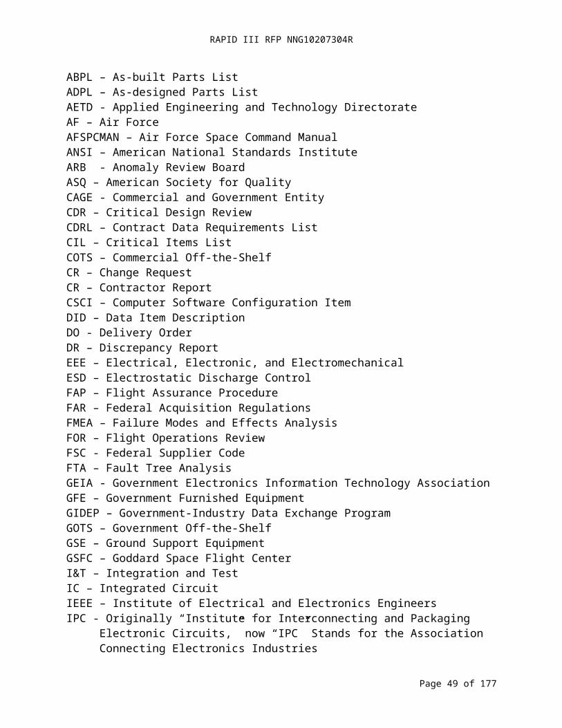
RAPID III RFP NNG10207304R
Applicable Document Name Document Number, Revision, & Date
MAR Section(s)
and//or DID(s) Document Sources and/or Notes to User
Department of Defense Inspection Program Requirements, Nondestructive for Aircraft and Missile Materials and Parts
MIL-HDBK-6870, Revision A, August 28, 2001
DID MA 12-5 http://www.everyspec.com/MIL-HDBK/MIL-HDBK+(3000+-+8999)/MIL-HDBK-6870A_10214/Note: This is not a Government/Issuing Organization website so documents are not under configuration management.
Guidelines for the Selection of Metallic Materials for Stress Corrosion Cracking Resistance in Sodium Chloride Environment
MSFC-STD-3029, Revision A, February 24, 2005
DID MA 12- http://standards.nasa.gov/documents/msfc
Nondestructive Evaluation Requirements for Fracture-Critical Metallic Components
NASA-STD-5009, Initial, April 7 2008
DID MA 12-5 http://standards.nasa.gov/documents/detail/3315641
Standard Materials and Processes Requirement for Spacecraft
NASA-STD-6016, Initial, July 2008
12.1; DID MA 12-1 through 12-5
http://standards.nasa.gov/released/NASA/NASA_STD_6016_APPROVED_2008_07_11.pdf
Standard for Lifting Devices and Equipment
NASA-STD-8719.9, Initial, October 1, 2007
3.2.2.2, DIDs MA 3-5, 6-1
http://www.hq.nasa.gov/office/codeq/doctree/87199.htm
Software Safety Standard NASA-STD-8719.13, Revision B with Change 1, July 8, 2004
4.3, 4.4, 5.1http://www.hq.nasa.gov/office/codeq/doctree/safeheal.htm
Process for Limiting Orbital Debris
NASA-STD-8719.14, Initial with Change 1, August 28, 2007
DID MA 3-10 http://www.hq.nasa.gov/office/codeq/doctree/safeheal.htm
Workmanship Standard for Staking and Conformal Coating of Printed Wiring Boards and Electronic Assemblies
NASA-STD-8739.1, Revision AMarch 2008
10.1 http://workmanship.nasa.gov/ws_8739_1.jsp
Workmanship Standard for Surface Mount Technology
NASA-STD-8739.2, Initial with Change 1, June 2008
10.1 http://workmanship.nasa.gov/ws_8739_2.jsp
Soldered Electrical Connections NASA-STD-8739.3, Initial with Change 3, June 2008
10.1 http://workmanship.nasa.gov/ws_8739_3.jsphttp://www.hq.nasa.gov/office/codeq/doctree/87393.htm
Page 49 of 126
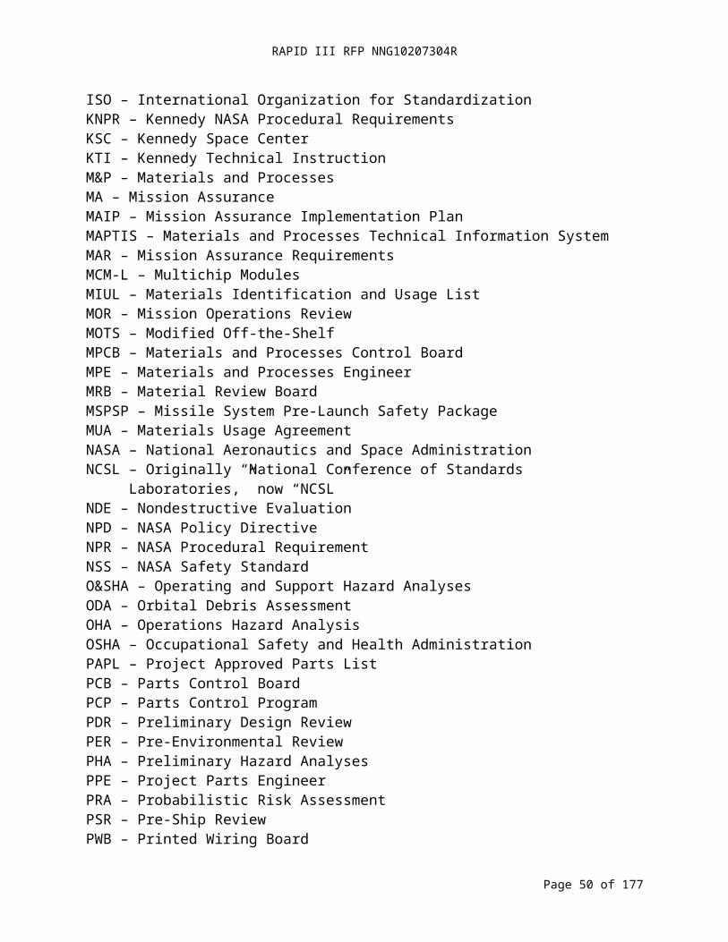
RAPID III RFP NNG10207304R
Applicable Document Name Document Number, Revision, & Date
MAR Section(s)
and//or DID(s) Document Sources and/or Notes to User
Crimping, Interconnecting Cables, Harnesses, and Wiring
NASA-STD-8739.4, Initial with Change 4, July 2008
10.1 http://workmanship.nasa.gov/ws_8739_4.jsp
Fiber Optic Terminations, Cable Assemblies, and Installation
NASA-STD-8739.5, Initial with Change 1, July 2008
10.1 http://workmanship.nasa.gov/ws_8739_5.jsphttp://www.hq.nasa.gov/office/codeq/87395.htm
NASA Standard for Software Assurance
NASA-STD-8739.8, Initial w/Change 1, July 28, 2004
5.1, DID MA 5-1, 5-2
http://www.hq.nasa.gov/office/codeq/doctree/87398.htmhttp://www.hq.nasa.gov/office/codeq/doctree/87398.pdf
NASA Software Engineering Requirements
NPR 7150.2, Initial, September 27, 2004
5.1; DIDs MA 5-2, 5-3, 5-4, & 5-5
http://nodis3.gsfc.nasa.gov/displayDir.cfm?t=NPR&c=7150&s=2
NASA Procedures and Guidelines for Mishap Reporting, Investigating, and Recordkeeping
NPR 8621.1, Revision B, May 23, 2006
3.2.7; DID MA 3-11
http://nodis3.gsfc.nasa.gov/displayDir.cfm?Internal_ID=N_PR_8621_001B_&page_name=mainhttp://www.hq.nasa.gov/office/codeq/doctree/safeheal.htm
Risk Classification for NASA Payloads
NPR 8705.4, Initial, June 14, 2004
A.1; DIDs MA 4-1 through 4-4
http://nodis3.gsfc.nasa.gov/displayDir.cfm?t=NPR&c=8705&s=4
Probabilistic Risk Assessment (PRA) Procedures for NASA Programs and Projects
NPR 8705.5 4.2; DIDs MA 4-1 & 4-2
http://nodis3.gsfc.nasa.gov/displayDir.cfm?t=NPR&c=8705&s=5
NASA General Safety Program Requirements
NPR 8715.3 Revision C with Change 3, March 12, 2008
3.1, 3.1.1, 4.2; DIDs MA 3-1, 3-4, 3-6, 3-9, 4-1, 4-2& 4-4
http://nodis3.gsfc.nasa.gov/displayDir.cfm?t=NPR&c=8715&s=3Chttp://www.hq.nasa.gov/office/codeq/doctree/safeheal.htm
NASA Procedural Requirements for Limiting Orbital Debris
NPR 8715.6A, Revision A, February 19, 2008
DID MA 3-10 http://www.hq.nasa.gov/office/codeq/doctree/safeheal.htm
Expendable Launch Vehicle Payload Safety Program
NPR 8715.7 3.1, 3.1.1; DID MA 3-1
http://nodis3.gsfc.nasa.gov/displayDir.cfm?t=NPR&c=8715&s=7http://www.hq.nasa.gov/office/codeq/doctree/safeheal.htm
Safety Standard for Explosives, Propellants, and Pyrotechnics
NSS 1740.12, Initial, August 1993
3.1.1 http://www.hq.nasa.gov/office/codeq/doctree/safeheal.htm
Guidelines and Assessment Procedures for Limiting Orbital Debris
NSS 1740.14, Initial, August 1995
3.1.1 http://www.orbitaldebris.jsc.nasa.gov/mitigate/safetystandard.htmlhttp://www.hq.nasa.gov/office/codeq/doctree/safeheal.htm
Page 50 of 126
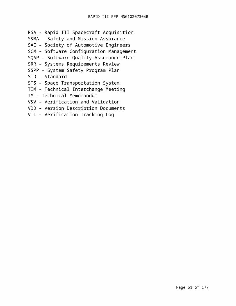
RAPID III RFP NNG10207304R
Applicable Document Name Document Number, Revision, & Date
MAR Section(s)
and//or DID(s) Document Sources and/or Notes to User
GIDEP Operations Manual S0300-BT-PRO-010, November 1994
15.1, 15.4; DIDs MA 15-1 & 15-2
Available at http://www.gidep.org .Note: Various sections/appendices of document were updated between April 1991 and March 2008.
GIDEP Requirements Guide S0300-BU-GYD-010, April 2008
15.1, 15.4; DIDs MA 15-1 & 15-2
Available at http://www.gidep.org .
Quality Systems - Aerospace- Model for Quality Assurance in Design, Development, Production, Installation and Servicing
SAE AS9100 Revision C, January 2009
2.1; DIDs MA 2-1 through 2-4
Purchase at: http://store.sae.org/
Material Selection List for Plastic Films, Foams, and Adhesive Tapes
KSC Form KTI-5211, Revision C
3.2.8; DID MA 3-12
http://kscsma.ksc.nasa.gov/ELVPayloadSafety/Requirements.html
Radiation Training & Experience Summary (Non-Ionizing)
KSC Form 16-450 NS, April 1999
3.2.8; DID MA 3-13
http://kscsma.ksc.nasa.gov/ELVPayloadSafety/Forms.html
Radiation Training & Experience Summary (Ionizing)
KSC Form 16-294 NS, July 2000
3.2.8; DID MA 3-13
http://kscsma.ksc.nasa.gov/ELVPayloadSafety/Forms.html
Laser Device Use Request/ Authorization
KSC Form 16-447, August 1991
3.2.8; DID MA 3-13
http://kscsma.ksc.nasa.gov/ELVPayloadSafety/Forms.html
Radiofrequency Microwave System Use Request/ Authorization
KSC Form 16-451 NS, August 1998
3.2.8; DID MA 3-13
http://kscsma.ksc.nasa.gov/ELVPayloadSafety/Forms.html
Radiation Use Request/ Authorization (Radioactive Materials)
KSC Form 16-295 NS, August 1998
3.2.8; DID MA 3-13
http://kscsma.ksc.nasa.gov/ELVPayloadSafety/Forms.html
Process Waste Questionnaire KSC Form 26-551 V2, August 2006
3.2.8; DID MA 3-14
http://kscsma.ksc.nasa.gov/ELVPayloadSafety/Forms.html
Request for Environmental Impact Analysis
AF Form 814 (EF-V1), August 1993
3.2.8, DID MA 3-15
Available at RSDO Website, http://rsdo.gsfc.nasa.gov/ .
Problem Impact Statement Parts, Materials and Safety
GSFC Form 4-37, August 2008
DID MA 5-1 Available at RSDO Website, http://rsdo.gsfc.nasa.gov/ .
Material Safety Data Sheet OSHA Form 20 or DD Form 1813,1986
DID MA 3-7 http://osha.gov/dsg/hazcom/msds-osha174/msdsform.html
Page 51 of 126

RAPID III RFP NNG10207304R
Reference Documents List
Reference Document Name Document Number, Revision, & Date
MAR Section(s)
and//or DID(s) Document Sources and/or Notes to User
NASA Fault Tree Handbook for Aerospace Applications
Version 1.1, August 2002
DID MA 4-4 http://www.hq.nasa.gov/office/codeq/doctree/fthb.pdf
Outgassing Data for Selecting Spacecraft Materials
On-Line, March 25, 2009
DID MA 13-1 http://outgassing.nasa.gov/
PRA Procedures Guide for NASA Managers and Practitioners
Version 1.1, August 2002
DID MA 4-2 http://www.hq.nasa.gov/office/codeq/doctree/praguide.pdf
Project Systems Review Plan No Information DIDs MA 8-1 & 8-2
This document is mission-specific. Obtain it from the Project Office.
IEEE Standard for Software Configuration Management Plans
ANSI-IEEE Standard 828-2005, January 2005
DIDs MA 5-3 & 5-5
Purchase at: https://sbwsweb.ieee.org/ecustomercme_enu/start.swe?SWECmd=GotoView&src=0&Join=n&SWEView=Catalog+View+(eSales)_Main_JournalMags_IEEE&mem_type=Customer&HideNew=N&SWEHo=sbwsweb.ieee.org&SWETS=1244080874
IEEE Guide to Software Configuration Management
ANSI-IEEE Standard 1042-1987
DIDs MA 5-3 &5-5
Purchase at: https://sbwsweb.ieee.org/ecustomercme_enu/start.swe?SWECmd=GotoView&src=0&Join=n&SWEView=Catalog+View+(eSales)_Main_JournalMags_IEEE&mem_type=Customer&HideNew=N&SWEHo=sbwsweb.ieee.org&SWETS=1244080874
Standard Test Methods for Total Mass Loss and Collected Volatile Condensable Materials from Outgassing in a Vacuum Environment
ASTM E595, December 1, 2007
DID MA 13-1 Purchase at http://www.astm.org/Standards/E595.htm .
Performing a Failure Mode and Effects Analysis
GSFC FAP P-322-208, DRAFT
DID MA 4-3 Available at RSDO Website, http://rsdo.gsfc.nasa.gov/ .
Engineering Peer Reviews GPR 8700.6, Revision A, January 26, 2005
DID MA 8-3 Available at RSDO Website, http://rsdo.gsfc.nasa.gov/
Rules for the Design, Development, Verification, and Operation of Flight Systems
GSFC-STD-1000, Revision E, July 13, 2009
DID MA 1-1, 6-1, 13-1
http://standards.gsfc.nasa.gov/gsfc-stds.html
Page 52 of 126

RAPID III RFP NNG10207304R
Reference Document Name Document Number, Revision, & Date
MAR Section(s)
and//or DID(s) Document Sources and/or Notes to User
Risk Management Reporting GSFC-STD-0002, Initial, May 8, 2009 DID MA 7-2 http://standards.gsfc.nasa.gov/gsfc-stds.html
Software Quality Assurance PlansIEEE Standard 730-
2002, September 2002
DID MA 5-1
Purchase at https://sbwsweb.ieee.org/ecustomercme_enu/start.swe?SWECmd=GotoView&src=0&Join=n&SWEView=Catalog+View+(eSales)_Main_JournalMags_IEEE&mem_type=Customer&HideNew=N&SWEHo=sbwsweb.ieee.org&SWETS=1244080874
Software Verification & Validation
IEEE Standard 1012-2004, January 2005 DID MA 5-2
Purchase at: https://sbwsweb.ieee.org/ecustomercme_enu/start.swe?SWECmd=GotoView&src=0&Join=n&SWEView=Catalog+View+(eSales)_Main_JournalMags_IEEE&mem_type=Customer&HideNew=N&SWEHo=sbwsweb.ieee.org&SWETS=1244080874
IEEE Guide for Software Verification and Validation Plans
IEEE Standard 1059-1993, January 1993 DID MA 5-2
Purchase at: https://sbwsweb.ieee.org/ecustomercme_enu/start.swe?SWECmd=GotoView&src=0&Join=n&SWEView=Catalog+View+(eSales)_Main_JournalMags_IEEE&mem_type=Customer&HideNew=N&SWEHo=sbwsweb.ieee.org&SWETS=1244080874
Standard Practice for System Safety
MIL-STD-882, Revision D, February
10, 2000DID MA 3-4
http://www.assistdocs.com/search/document_details.cfm?ident_number=36027&StartRow=1&PaginatorPageNumber=1&doc_id=MIL-STD-882&search_method=BASIC
Lubrication for Space Applications
NASA CR-2005-213424, Initial, January 2005
DID MA 12-2 http://gltrs.grc.nasa.gov/cgi-bin/GLTRS/browse.pl?2005/CR-2005-213424.html
Planning, Developing and Managing an Effective Reliability
and Maintainability (R&M) Program
NASA-STD-8729.1, Initial, December
1998DID MA 4-1 http://www.hq.nasa.gov/office/codeq/doctree/87291.htm
Lubrication Handbook for the Space Industry
(Part A: Solid Lubricants, Part B: Liquid Lubricants)
NASA-TM-86556, Initial, December
1985DID MA 12-2
http://www.everyspec.com/NASA/NASA+(General)/NASA_TM-86556_6268/Note: This is not a Government/Issuing Organization website so documents are not under configuration management.
Reliability and Maintainability (R&M) Program Policy
NPD 8720.1, Revision C, April 18,
2008DID MA 4-1 http://nodis3.gsfc.nasa.gov/displayDir.cfm?t=NPD&c=8720&s=1C
Agency Risk Management Procedural Requirements
NPR 8000.4, Revision A,
December 16, 2008
DIDs MA 7-1 & 7-2 http://nodis3.gsfc.nasa.gov/displayDir.cfm?t=NPR&c=8000&s=4A
Page 53 of 126
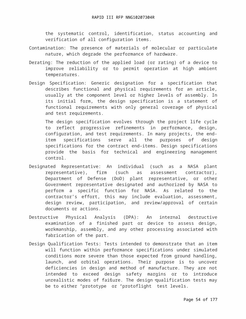
RAPID III RFP NNG10207304R
Appendix D.
MAR Contract Data Requirements List (CDRL)
Page 54 of 126

RAPID III RFP NNG10207304R
DID No. Section Title Due PurposeMA 1-1 1.1 Mission Assurance Implementation Plan 1. Mission Specific MAIP with DO Proposal. ApprovalMA 1-2 1.7 Previously Developed Product – Compliance with
RequirementsThirty (30) days after identification of previously developed product
Approval
MA 2-1 2.1 Quality Manual 30 days after DO award ReviewMA 2-2 2.2.2 Reporting of MRB Actions 1. Major MRB actions: within five (5) working days of MRB
action2. Minor MRB actions: within five (5) working days of MRB
action
1. Review2. Review
MA 2-3 2.2.2 Request for a Deviation or Waiver Within five (5) working days of identifying the need for a deviation or waiver
Approval
MA 2-4 2.2.3 Anomaly Report 1. Initial submission to the project office within 24 hours of occurrence
2. Notice of a change in status within 24 hours of occurrence3. Proposed closure to the project office prior to closure
1. Information2. Information3. Review
MA 3-1 3.1 System Safety Program Plan 1. To Project Office 15 days prior to Systems Requirements Review (SRR)
2. To Launch Range within 30 days of delivery to Project Office (following approval by the Project Office)
1. Approval2. Review
MA 3-2 3.1.2 Safety Procedures for Payload I&T 1. Payload I&T Procedures: twenty-one (21) days before first use
2. Launch Range Hazardous Procedures: Sixty (60) days prior to first use
3. Launch Range Hazardous Procedures: To Range Safety Twenty one (21) days prior to first use (following approval by the Project Office)
Approval
MA 3-3 3.2.1 Safety Requirements Compliance Checklist Thirty (30) days prior to Preliminary Design Review (PDR) ApprovalMA 3-4 3.2.2.1 Preliminary Hazard Analysis With MSPSP (DID MA 3-7) no later than thirty (30) days after
Mission PDRApproval
MA 3-5 3.2.2.2 Operations Hazard Analysis Forty-five (45) days prior to Pre-Environmental Review (PER) ApprovalMA 3-6 3.2.2.3 Operating and Support Hazard Analysis As a part of the MSPSP (DID MA 3-7) Approval
Page 55 of 126

RAPID III RFP NNG10207304R
DID No. Section Title Due PurposeMA 3-7 3.2.3 Missile System Prelaunch Safety Package
(MSPSP)1. Preliminary MSPSP: Thirty (30) days after Mission PDR2. Intermediate MSPSP: Thirty (30) days prior to Mission
Critical Design Review (CDR)3. Final MSPSP: Sixty (60) days prior to
Spacecraft/Observatory shipment to Launch Range4. Final MSPSP: To Range Safety within ten (10) days after
approval by the Project Office
Approval
MA 3-8 3.2.4 Verification Tracking Log 1. With the final MSPSP DID (MA 3-7), identifying hazard controls that are not verified as closed
2. Updates: After Pre-Ship Review (PSR), provide weekly until all hazard controls are verified as closed
Review
MA 3-9 3.2.5 Safety Variance Within thirty (30) days of identifying the need for a variance ApprovalMA 3-10 3.2.6 Orbital Debris Assessment 1. Preliminary Package: Fifteen (15) days prior to mission
PDR2. Final Package: Sixty (60) days prior to mission CDR3. Updates to the final package within thirty (30) days of
identification of design changes that affect the assessment
1. Review2. Approval3. Approval
MA 3-11 3.2.7 Mishap Preparedness and Contingency Plan 30 days prior to mission PDR ReviewMA 3-12 3.2.8 Material Selection List for Plastic Films, Foams,
and Adhesive TapesWith the Final MSPSP (DID MA 3-7) Review
MA 3-13 3.2.8 Radiation Forms and Analyses With the Final MSPSP (DID MA 3-7) ReviewMA 3-14 3.2.8 Process Waste Questionnaire With the Final MSPSP (DID MA 3-7) ReviewMA 3-15 3.2.8 Environmental Impact Statement With the Final MSPSP (DID MA 3-7) ReviewMA 4-1 4.1 Probabilistic Risk assessment (PRA) and
Reliability Program Plan and Reports1. Final plans fifteen (15) days prior to the Systems
Requirements Review (SRR)2. Activity reports at milestone reviews beginning with the
Systems Requirements Review
1. Review2. Review
MA 4-2 4.2 Probabilistic Risk Assessment 1. Interim report thirty (30) days prior to SRR2. Updated interim report thirty (30) days prior to CDR3. Updated interim report thirty(30) days prior to Mission
Operations Review (MOR)4. Final report thirty (30) days prior to Flight Operations
Review (FOR)
1. Information2. Review3. Review4. Review
Page 56 of 126

RAPID III RFP NNG10207304R
DID No. Section Title Due PurposeMA 4-3 4.3 Failure Mode and Effects Analysis (FMEA) and
Critical Items List (CIL)1. Preliminary FMEA thirty (30) days before PDR2. Final FMEA thirty (30) days prior to CDR3. Updated FMEA and CIL thirty (30) days prior to each
subsequent milestone review leading up to Launch
1. Review2. Review3. Review
MA 4-4 4.4 Fault Tree Analysis Quantitative FTA report in support of safety pivotal event analysis as part of each PRA report
Review
MA 4-5 4.11 Limited-Life Items List 1. Thirty (30) days prior to PDR2. Updates to the Project Office no later than thirty (30) days
after changes
Review
MA 5-1 5.2 Software Quality Assurance Plan 1. Preliminary plan: Fifteen (15) days prior to the SRR2. Baseline plan: Fifteen (15) days prior to PDR3. Updates: Fifteen (15) days prior to implementation
1. Review2. Review3. Review
MA 5-2 5.3 Software Verification and Validation Plan 1. Preliminary plan: Thirty (30) days after DO award2. Final Baseline plan: fifteen (15) days prior to SRR3. Updates: Fifteen (15) days prior to implementation
1. Review2. Review3. Review
MA 5-3 5.5 Software Configuration Management Plan 1. Preliminary plan: Thirty (30) days after DO award2. Final Baseline plan: Fifteen (15) days prior to SRR3. Updates: Fifteen (15) days prior to implementation
1. Review2. Review3. Review
MA 5-4 5.7 Software Version Description Document With each build or release InformationMA 5-5 5.8 Software Status Report Monthly beginning sixty (60) days after DO award InformationMA 6-1 6.2 Ground Systems and Equipment Plan Thirty (30) days prior to SRR ReviewMA 7-1 7.1 Risk Management Plan Fifteen (15) days prior to the SRR ApprovalMA 7-2 7.2 Risk List Fifteen (15) days prior to each milestone review beginning with
PDRReview
MA 9-1 9.1 System Performance Verification Plan 1. Final plan due thirty (30) days prior to CDR. (Note: The Contract baseline plan is provided with the Core Spacecraft Proposal. The initial plan for each mission specific DO is provided with the DO Proposal.)
1. Approval
MA 9-2 9.2 Environmental Verification Plan 1. Final plan due thirty (30) days prior to CDR. (Note: The Contract baseline plan is provided with the Core Spacecraft Proposal. The initial plan for each mission specific DO is provided with the DO Proposal.)
1. ApprovalApproval
MA 9-3 9.3 System Performance Verification Matrix Updated matrix included in the data packages for the reviews beginning with PDR. (Note: The Contract baseline plan is
Review
Page 57 of 126

RAPID III RFP NNG10207304R
DID No. Section Title Due Purposeprovided with the Core Spacecraft Proposal. The initial plan for each mission specific DO is provided with the DO Proposal.)
MA 9-4 9.4 Environmental Test Matrix Updated matrix included in the data packages for reviews beginning with PDR. (Note: The Contract baseline plan is provided with the Core Spacecraft Proposal. The initial plan for each mission specific DO is provided with the DO Proposal.)
Review
MA 9-5 9.5 Verification Reports 1. Preliminary verification report: Within seventy-two (72) hours of test completion
2. Final verification report: Within thirty (30) days of test completion
Information
MA 9-6 9.6 System Performance Verification Report 1. Updated reports: With the review data package at milestone reviews, beginning with PDR
2. Final report: Within thirty (30) days after completion of on-orbit checkout
Information
MA 10-1 10.3 ESD Control Plan Fifteen (15) days prior to the SRR ReviewMA 11-1 11.1 Parts Control Program Plan Fifteen (15) days prior to the SRR ApprovalMA 11-2 11.2 Parts Control Board Operating Procedures Sixty (60) days after DO award ReviewMA 11-3 11.3.1 Project Approved Parts List (PAPL) Ten (10) business days prior to the PCB meeting at which they
will be presentedReview
MA 11-4 11.3.2 As Designed Parts List (ADPL) Ten (10) business days prior to the PCB meeting at which they will be presented
Review
MA 11-5 11.3.3 As Built Parts List (ABPL) 1. EEE Parts Information – Ten (10) business days prior to the PCB meeting at which they will be reviewed
2. ABPL: Fifteen (15) work business prior to PSR
1. Review2. Review
MA 12-1 12.1 Materials & Processes Selection, Implementation, & Control Plan
Fifteen (15) days prior to the SRR Approval
MA 12-2 12.2 Life Test Plan and Reports for Lubricated Mechanisms
1. Plan: Thirty (30) days prior to PDR2. Test report: Thirty (30) days after mechanism’s acceptance
test completion
1. Review2. Review
MA 12-3 12.3 Materials Usage Agreement 1. Initial Submission: All MUAs thirty (30) days prior to CDR2. After Initial Submission: New or revised MUAs within
thirty (30) days of identification
1. Approval2. Approval
MA 12-4 12.4 Materials Identification and Usage List 1. Thirty (30) days prior to PDR2. Updates: Within thirty (30) days of identification
Review
MA 12-5 12.5 Nondestructive Evaluation Plan 1. Thirty (30) days prior to PDR 1. Review
Page 58 of 126
RAPID III RFP NNG10207304R
DID No. Section Title Due Purpose2. Updates: Within thirty (30) days after identification 2. Review
Page 59 of 126
RAPID III RFP NNG10207304R
DID No. Section Title Due PurposeMA 12-6 12.6 Printed Wiring Boards Test Coupons and/or
Coupon Analysis Reports1. Coupons & Supporting Manufacturing Information: As
soon as practicable (unless sent to a Project Office/Customer-approved laboratory)
2. Coupon Analysis Reports From a Project Office/Customer-Approved Laboratory: Within ten (10) days of receipt from laboratory
Approval
MA 13-1 13.1 Contamination Control Plan and Data 1. Initial Plan: Thirty (30) days before PDR2. Final Plan: Thirty (30) days before the CDR3. Final Thermal Vacuum Bakeout Results: Within thirty (30)
of completion4. Contamination Certificate of Compliance: With End Item
Acceptance Data Package (DID MA 16-1)
1. Review2. Approval3. Review4. Review
MA 15-1 15.4 GIDEP Alert and NASA Advisory Dispositions 1. Existing Alert Submittal(s): Alert disposition within thirty (30) days of identification of potential use, or use, of a EEE part or material
2. New/Subsequent Alert Submittals: Alert disposition within thirty (30) days of Alert receipt
Review
MA 15-2 15.4 Documentation on Significant Parts, Materials, and Safety Problems
Within thirty (30) days of identification Review
MA 16-1 16.1 End Item Acceptance Data Package Thirty (30) days prior to end item delivery Approval
Page 60 of 126
RAPID III RFP NNG10207304R
Appendix E. MAR Data Item Descriptions (DIDs)
Page 61 of 126
RAPID III RFP NNG10207304R
DID MA 1-1: MISSION ASSURANCE IMPLEMENTATION PLAN (10-21-2008)
Title:Mission Assurance Implementation Plan
DID No.:MA 1-1
Reference:MAR Paragraph 1.1
Use:Documents the Contractor’s plan for implementing a system safety and mission assurance program.- GSFC-STD-1000, Rules for the Design, Development, Verification, and Operation of
Flight SystemsPlace/Time/Purpose of Delivery:- Mission Specific MAIP – Delivered to the Government with the Delivery Order
Proposal for approval.Preparation Information:
The MAIP shall cover:- All flight hardware and software that is designed, built, or provided by the
Contractor and its subcontractors, or furnished by the Government, from project initiation through launch and mission operations.
- The ground system equipment that interfaces with flight equipment to the extent necessary to assure the integrity and safety of flight items (includes electrical, mechanical, software, and test facilities).
- Documentation of compliance with GSFC-STD-1000, Rules for the Design, Development, Verification, and Operation of Flight Systems
The MAIP shall include a traceability matrix for the mission assurance requirements
Page 62 of 126

RAPID III RFP NNG10207304R
DID MA 1-2: PREVIOUSLY DEVELOPED PRODUCT – COMPLIANCE WITH REQUIREMENTS (04-18-2008)
Title:Previously Developed Product – Compliance with Requirements
DID No.:MA 1-2
Reference:MAR Paragraph 1.7
Use:Documents the compliance of previously developed product with the requirements of the SOW and the MAIP.
Related Documents:- Contractor’s Mission Assurance Implementation Plan
Place/Time/Purpose of Delivery:- Delivered to the Project Office thirty (30) days after identification of the previously
developed product for approval.
Preparation Information:The document shall identify the requirements that apply to the previously developed product through a requirements compliance matrix for the product’s specific characteristics and its development. The document shall address all areas of noncompliance through a waiver or deviation.
Page 63 of 126
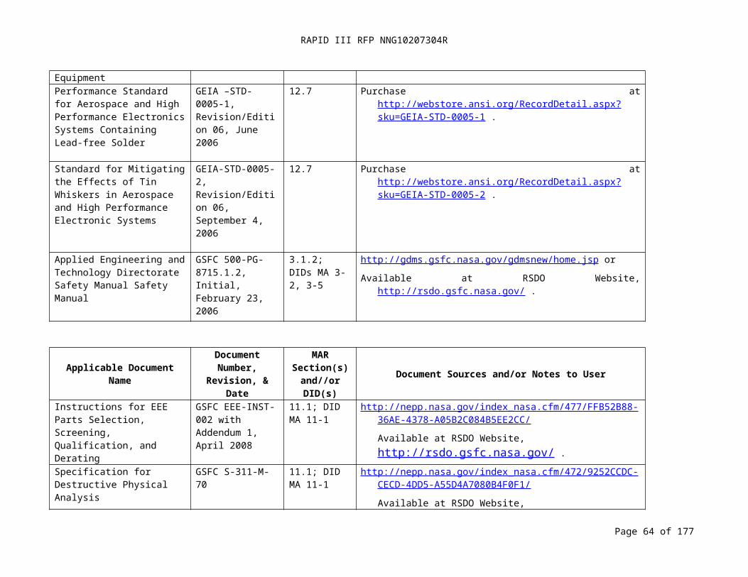
RAPID III RFP NNG10207304R
DID MA 2-1: QUALITY MANUAL (10-21-2008)
Title:Quality Manual
DID No.:MA 2-1
Reference:MAR Paragraph 2.1
Use:Documents the Contractor's quality management system.
Related Documents:- SAE AS9100, Quality Systems - Aerospace - Model for Quality Assurance in Design,
Development, Production, Installation and Servicing- ANSI/ISO/ASQC Q9001:2000, Quality Management Systems - Requirements- ISO/TR 10013, Guidelines for Quality Management System Documentation
Place/Time/Purpose of Delivery:- Deliver to the Project Office thirty (30) days after Delivery Order award for review.
Preparation Information:Prepare a Quality Manual addressing applicable requirements of AS9100 or ANSI/ISO/ASQC 9001; refer to ISO/TR 10013 for guidelines on preparation of a quality manual.
Page 64 of 126
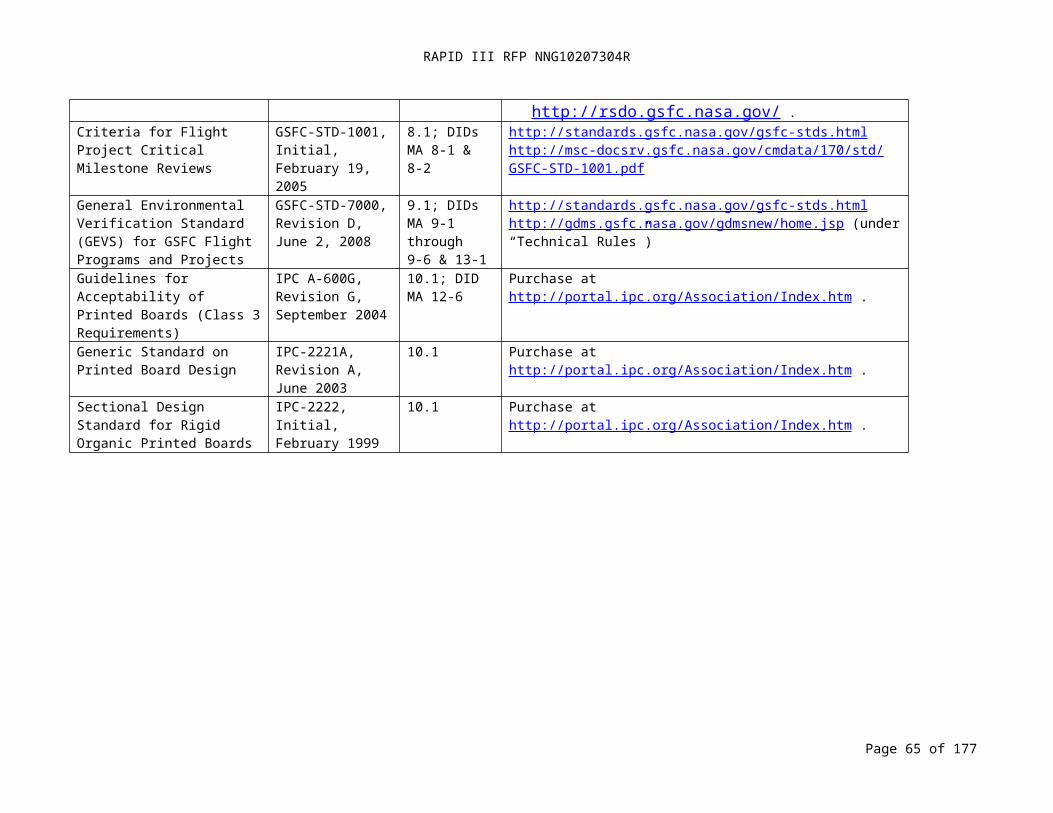
RAPID III RFP NNG10207304R
DID MA 2-2: REPORTING OF MRB ACTIONS (07-11-2008)
Title:Reporting of MRB Actions
DID No.:MA 2-2
Reference:MAR Paragraph 2.2.2
Use:Report MRB actions to the project office.
Related Documents:- SAE AS9100, Quality Systems - Aerospace - Model for Quality Assurance in Design,
Development, Production, Installation and ServicingPlace/Time/Purpose of Delivery:- Major MRB actions: Deliver to the Project Office within five (5) working days of MRB
action for review.- Minor MRB actions: Deliver to the Project Office within five (5) working days of MRB
action for review.Preparation Information:
The Contractor shall document relevant information on a Contractor MRB form that includes at least the following:- Identification of project, system, or sub-system;- Identification of item (e.g., assembly, sub-assembly, or part, to include serial number or
part number as applicable);- Description of affected item;- Definition of major and minor nonconformances;- Identification of next higher assembly;- Description of anomaly, including activities leading up to the anomaly;- Names and contact information of involved individuals;- Status of item;- Contact information for personnel who originated the report;- Date of original submission to the MRB; and- Actions taken after approval.
Page 65 of 126
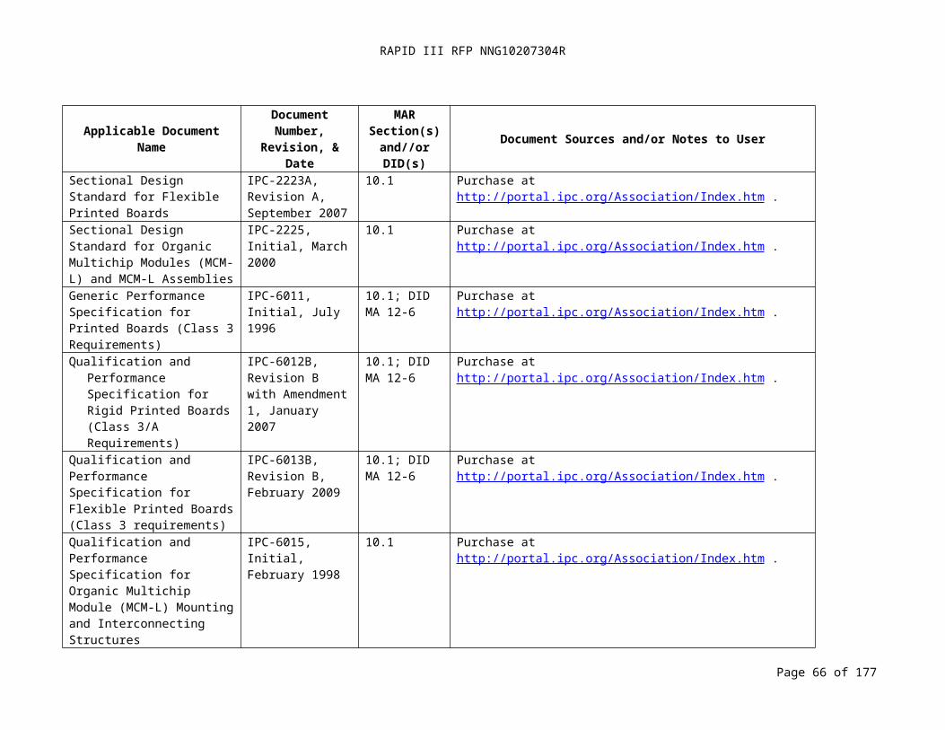
RAPID III RFP NNG10207304R
17.2
DID MA 2-3: REQUEST FOR A DEVIATION OR WAIVER (04-18-2008)
Title:Request for a deviation or waiver
DID No.:MA 2-3
Reference:MAR Paragraph 2.2.2
Use:Request Project Office approval of a deviation or waiver.
Related Documents:- SAE AS9100, Quality Systems - Aerospace - Model for Quality Assurance in Design,
Development, Production, Installation and Servicing
Place/Time/Purpose of Delivery:Deliver to the Project Office within five (5) working days of identifying the need for a deviation or waiver for approval.
Preparation Information:The Contractor shall identify the requirements that apply to the product and provide specific information regarding the noncompliance of the product with the requirements. The Contractor shall identify the effect of the proposed noncompliance on product performance at higher levels of assembly.
Page 66 of 126
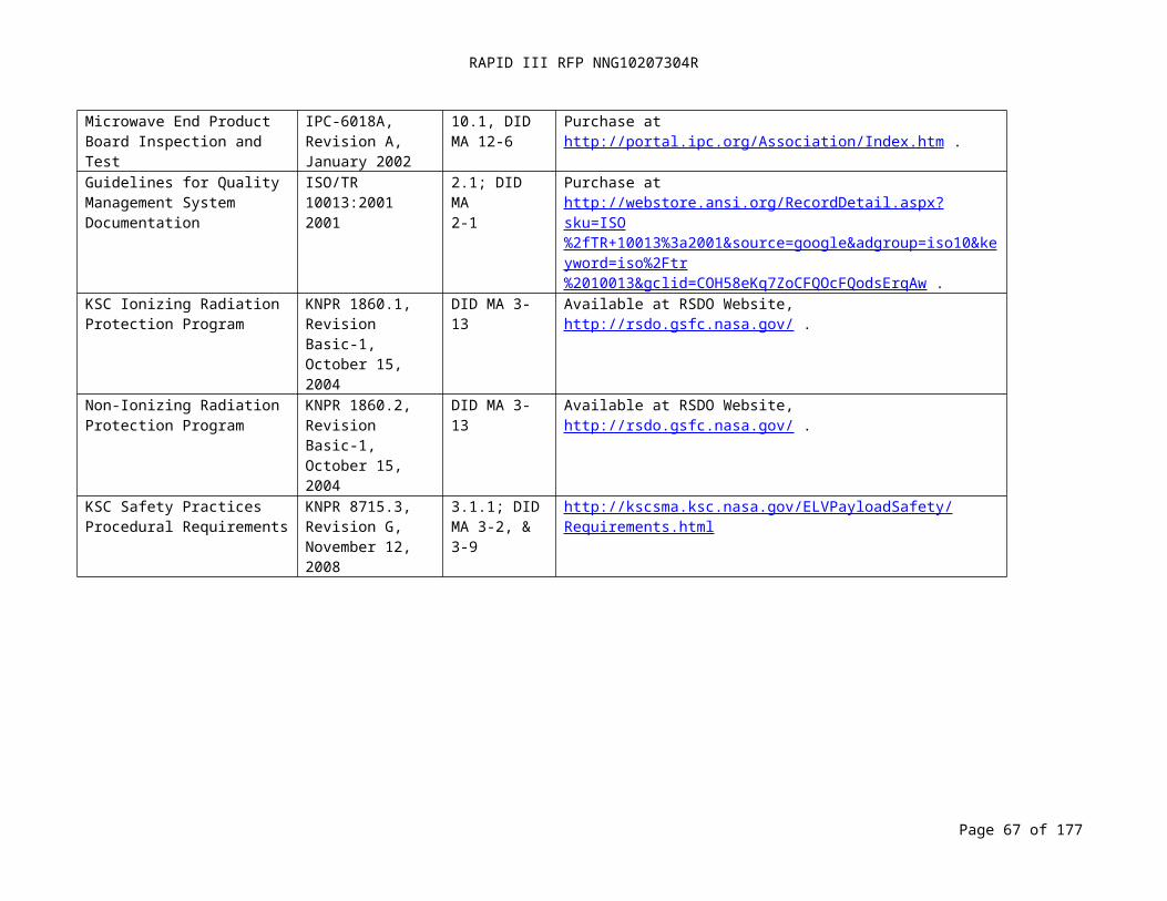
RAPID III RFP NNG10207304R
DID MA 2-4: ANOMALY REPORT (02-19-2009)
Title:Anomaly Report
DID No.:MA 2-4
Reference:MAR Paragraph 2.2.3
Use:Document anomalies, investigative activities, rationale for closure, and corrective and preventive actions.
Related Documents:- SAE AS9100, Quality Systems - Aerospace - Model for Quality Assurance in Design,
Development, Production, Installation and ServicingPlace/Time/Purpose of Delivery:- Deliver initial submission to the Project Office within 24 hours of occurrence for
information.- Deliver notice of a change in status within 24 hours of occurrence to the Project Office
for information.- Deliver the proposed closure to the Project Office prior to closure for review to ensure
reports are accurate and complete.Preparation Information:
Document anomalies, changes in status, or proposed closure to identify the following information:- Identification of project, system, or sub-system;- Identification of failed item (e.g., assembly, sub-assembly, or part);- Description of item;- Identification of next higher assembly;- Description of anomaly, including activities leading up to anomaly, if known;- Names and contact information of individuals involved in anomaly;- Date and time of anomaly;- Status of item;- Contact information for personnel who originated the report;- Date of original submission;- Anomaly cause;- Corrective actions implemented;- Retesting performed and results;- Other items affected; and- Risk ratings—mission impact and certainty in corrective actions.
Page 67 of 126

RAPID III RFP NNG10207304R
DID MA 3-1: SYSTEM SAFETY PROGRAM PLAN (04-24-2008)
Title: System Safety Program Plan
DID No.: MA 3-1
Reference: MAR Paragraph 3.1
Use: The System Safety Program Plan (SSPP) describes the tasks and activities of system safety management and engineering required to identify, evaluate, and eliminate or control hazards to the hardware, software, and system design by reducing the associated risk to an acceptable level throughout the system life cycle, including launch range safety requirements.
Related Documents: - NPR 8715.3, NASA General Safety Program Requirements, Paragraph 2 - NPR 8715.7, Expendable Launch Vehicle Payload Safety Program- AFSPCMAN 91-710, Range Safety User Requirements Manual, Volume 1, Attachment
2Place/Time/Purpose of Delivery: - Deliver to the Project Office fifteen (15) days prior to Systems Requirements Review
(SRR) for approval.- After receiving Project Office approval, deliver to the Launch Range for review within
thirty (30) days of delivery to Project Office.
Page 68 of 126

RAPID III RFP NNG10207304R
DID MA 3-1: SYSTEM SAFETY PROGRAM PLAN (04-24-2008) (CONTINUED)
Preparation Information: The Contractor shall prepare a SSPP that describes the development and implementation of a system safety program that complies with the requirements of NPR 8715.3, NPR 8715.7, the launch service provider, and launch range safety. Refer to AFSPCMAN 91-710, Volume 1, Attachment 2. The Contractor shall:- Define the roles and responsibilities of personnel.- Define the required documentation, applicable documents, and completion schedules
for analyses, reviews, and safety packages.- Address support for Reviews, Safety Working Group Meetings, and Technical
Interchange Meetings (TIMs).- Provide for early identification and control of hazards to personnel, facilities, support
equipment, and the flight system during product development, including design, fabrication, test, transportation, and ground activities.
- Address compliance with the launch range safety requirements.- Include a safety review process that meets the requirements of NPR 8715.7.- Address compliance with industrial safety requirements imposed by NASA and
Occupational Safety and Health Administration (OSHA) design and operational needs (e.g., NASA-STD-8719.9, Standard for Lifting Devices and Equipment) and contractually imposed mission unique obligations.
- Address software safety to identify and mitigate safety-critical software products by the following:- Identification of software related hazards;- Identification of hazard controls that are implemented with software;- Identification and tracking of software safety requirements;- Verification results and approved waivers and exceptions for software safety
requirements; and- Verification of safety discrepancy disposition approvals.
Page 69 of 126

RAPID III RFP NNG10207304R
DID MA 3-2: SAFETY PROCEDURES FOR PAYLOAD I&T (01-09-2009)
Title:Hazardous Procedures for Payload I&T and Pre-launch Processing
DID No.:MA 3-2
Reference:MAR Paragraph 3.1.2
Use:Documents hazardous procedures and associated safeguards that the Contractor shall use for launch vehicle payload integration and test activities and pre-launch activities that comply with the applicable safety requirements of the installation where the activities are performed.
Related Documents:- GSFC 500-PG-8715.1.2, AETD Safety Manual (for GSFC I&T operations)- AFSPCMAN 91-710, Range Safety User Requirements Manual- KNPR 8715.3, KSC Safety Practices Procedural Requirements
Place/Time/Purpose of Delivery:- Submit Payload I&T Hazardous Procedures to the Project Office seven (7) days before first
use for approval.- Submit Launch Range Hazardous Procedures to the Project Office sixty (60) days prior to
first use for approval.- After receiving Project Office approval, submit Launch Range Hazardous Procedures to
Range Safety twenty one (21) days prior to first use for approval.Preparation Information:
Examples of hazardous procedures include, but are not limited to, the following topics: Pressurized propellant systems - pressurization (pneumastat and hydrostat), loading and
unloading, sampling, leak testing, venting. Launch vehicle and payload systems - pressurization, loading and unloading, leak test,
erection and lifting with ordnance and/or propellant, application of power with ordnance and/or propellant, safe and arm pin removal, mate and demate operation.
Hazardous facilities - high pressure systems, propellant flows in ground systems, propellant cart loading, ordnance checkout and installation, X-ray operations, cryogenic operations, fixture proof tests, emergency blackout procedures.
Ordnance - bore scope, X-ray, continuity test, propellant trimming, installation, electrical connection and disconnection.
Work involving lasers, high energy RF emissions, radioactive materials, and hazardous materials.
Page 70 of 126
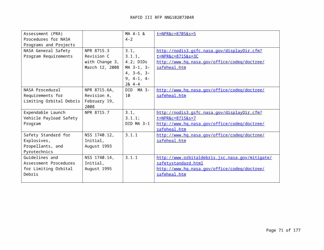
RAPID III RFP NNG10207304R
DID MA 3-3: SAFETY REQUIREMENTS COMPLIANCE CHECKLIST (04-18-2008)
Title:Safety Requirements Compliance Checklist
DID No.:MA 3-3
Reference:MAR Paragraph 3.2.1
Use:The checklist indicates for each requirement whether the proposed design is compliant, non-compliant but meets intent, non-compliant, or if the requirement is not applicable. An indication other than compliant shall include rationale.
Note: the Contractor shall submit safety waivers for non-compliant design elements per paragraph 3.2.5 and DID MA 3-9.
Related Documents:- AFSPCMAN 91-710, Range Safety User Requirements Manual- Reference MAR Section 3.1.1, Mission Related Safety Requirements Documentation
Place/Time/Purpose of Delivery:- Deliver to the Project Office thirty (30) days prior to the Preliminary Design Review
(PDR) for approval.Preparation Information:
The Contractor shall prepare a compliance checklist of all design, test, analysis, and data submittal requirements. The following shall be included:- Criteria and requirement;- System;- Indication of compliance, noncompliance, or not applicable;- Resolution;- Reference; and- Copies of all Range Safety approved non-compliances including waivers and equivalent
levels of safety certifications.
Page 71 of 126

RAPID III RFP NNG10207304R
DID MA 3-4: PRELIMINARY HAZARD ANALYSIS (04-18-2008)
Title:Preliminary Hazard Analysis
DID No.:MA 3-4
Reference:MAR Paragraph 3.2.2.1
Use:The Preliminary Hazard Analysis (PHA) is used to obtain an initial risk assessment and identify safety critical areas of a concept or system. It is based on the best available data, including mishap data from similar systems and other lessons learned. The Contractor shall evaluate hazards associated with the proposed design or function for severity, probability, and operational constraints. The Contractor shall identify safety provisions and alternatives that are needed to eliminate hazards or reduce their associated risk to an acceptable level.
Related Documents:- AFSPCMAN 91-710, Range Safety User Requirements Manual- NPR 8715.3, NASA General Safety Program Requirements- MIL-STD-882, Standard Practice for System Safety
Place/Time/Purpose of Delivery:- Submit the PHA with the MSPSP to the Project Office no later than thirty (30) days
after Mission PDR for approval.Preparation Information: The Contractor shall perform and document a PHA to identify safety critical areas, to provide an initial assessment of hazards, and to identify requisite hazard controls and follow-on actions. The results of the PHA shall be used to provide guidance for the tailoring of AFSPCMAN 91-710. Based on the best available data, including mishap data from similar systems and other lessons learned, hazards associated with the proposed design or function shall be evaluated for hazard severity, hazard probability, and operational constraint. Safety studies identifying provisions and alternatives needed to eliminate hazards or reduce their associated risk to an acceptable level shall be included. At a minimum, the PHA shall consider the following for identification and evaluation of hazards:
Hazardous components such as fuels, propellants, lasers, explosives, toxic substances, hazardous construction materials, pressure systems, and other energy sources.
Safety related interface considerations among various elements of the system such as material compatibility, electromagnetic interference, inadvertent activation, fire and explosive initiation and propagation, and hardware and software controls. This shall include consideration of the potential contribution by software, including software developed by other contractors and sources, to subsystem and system mishaps.
Safety design criteria to control safety-critical software commands and responses such as inadvertent command, failure to command, untimely command or responses, inappropriate magnitude, or designated undesired events shall be identified and appropriate action taken to incorporate them in the software and related hardware specifications.
Environmental constraints including the operating environments such as drop, shock, vibration, extreme temperatures, humidity, noise, exposure to toxic substances, health hazards, fire, electrostatic discharge, lightning, electromagnetic environmental effects,
Page 72 of 126
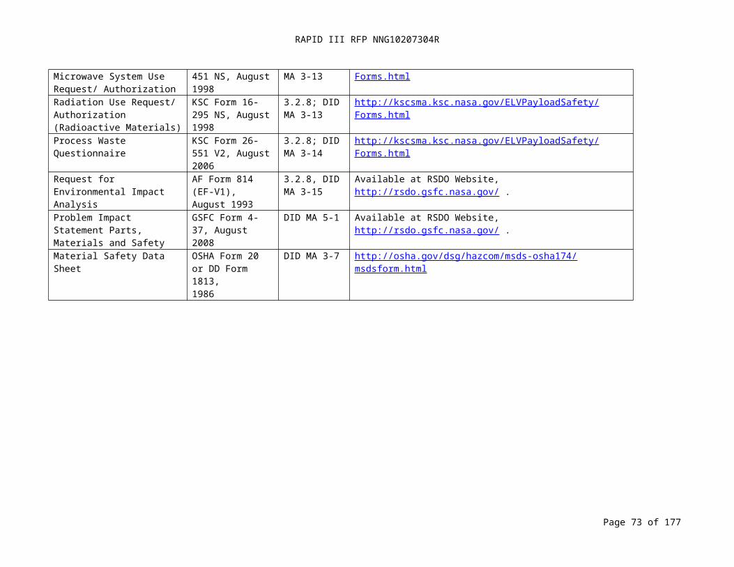
RAPID III RFP NNG10207304R
ionizing and non-ionizing radiation including laser radiation.DID MA 3-4: PRELIMINARY HAZARD ANALYSIS (04-18-2008) (CONTINUED)
Operating, test, maintenance, built-in-tests, diagnostics, and emergency procedures (human factors engineering, human error analysis of operator functions, tasks, and requirements; effect of factors such as equipment layout, lighting requirements, potential exposures to toxic materials, effects of noise or radiation on human performance; explosive ordnance render safe and emergency disposal procedures; life support requirements and their safety implications in manned systems, crash safety, egress, rescue, survival, and salvage).
Those test unique hazards that will be a direct result of the test and evaluation of thearticle or vehicle.
Facilities, real property installed equipment, support equipment such as provisions for storage, assembly, checkout, proof testing of hazardous systems and assemblies that may involve toxic, flammable, explosive, corrosive, or cryogenic materials and wastes; radiation or noise emitters; and electrical power sources.
Training and certification pertaining to hazardous and safety critical operations and maintenance of hazardous and safety critical systems.
Safety related equipment, safeguards, and possible alternate approaches such as interlocks; system redundancy; fail-safe design considerations using hardware or software controls; subsystem protection; fire detection and suppression systems; personal protective equipment; heating, ventilation, and air-conditioning; and noise or radiation barriers.
Malfunctions to the system, subsystems, or software. Each malfunction shall be specified, the cause and resulting sequence of events determined, and the degree of hazard.
Page 73 of 126

RAPID III RFP NNG10207304R
DID MA 3-5: OPERATIONS HAZARD ANALYSIS (04-18-2008)
Title:Operations Hazard Analysis
DID No.:MA 3-5
Reference:MAR Paragraph 3.2.2.2
Use:The operations hazard analysis (OHA) shall demonstrate that hazards related to the operation of hardware and test equipment during integration and test activities have been addressed with respect to facility safety requirements.
Related Documents:- GSFC 500-PG-8715.1.2, AETD Safety Manual (for operations at GSFC)- NASA-STD-8719.9, Standard for Lifting Devices and Equipment
Place/Time/Purpose of Delivery:- Deliver the OHA and Hazard Tracking Log to the Project Office forty-five (45) days prior
to Per-Environmental Review (PER) for approval.Preparation Information: The OHA shall include the following information:- Introduction – a summary of the major findings of the analysis and the proposed corrective
actions and definitions of special terms, acronyms, and abbreviations. - System Description – a description of system hardware and configuration, with a list of
subsystem components and schedules for integration and testing.- Analysis of Hazards.- List of real or potential hazards to personnel, equipment, and property during I&T
processing. - The following information shall be included for each hazard:- System Component/Phase – the phase and component with which the analysis is
concerned; e.g., system, subsystem, component, operating/maintenance procedure, or environmental condition.
- System Description and Hazard Identification, Indication:- A description of expected results from operating the
component/subsystem or performing the operating/maintenance action.- A complete description of the actual or potential hazard resulting from
normal actions or equipment failures; indicate whether the hazard shall cause personnel injury and equipment damage.
- A description of indications which include means of identifying the hazard to operating or maintenance personnel.
- A description of the safety hazards of software controlling hardware systems where the hardware effects are safety critical.
- Effect on System – the detrimental effects of an uncontrolled hazard on the system
- Risk Assessment. - Caution and Warning Notes – a list of warnings, cautions, procedures required in
test plans, test procedures, and/or work orders.- Status/Remarks – the status of actions to implement hazard controls. These actions
shall be verified as closed before the associated procedure or test can commence.
Page 74 of 126
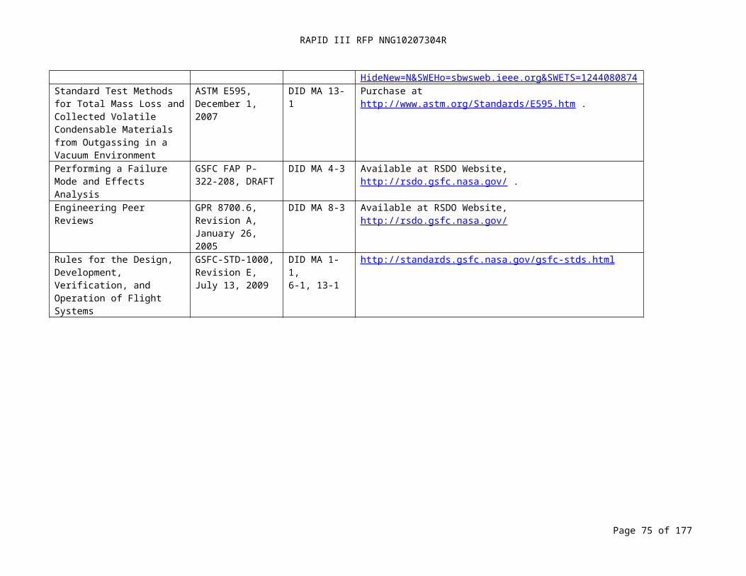
RAPID III RFP NNG10207304R
- References (e.g., test reports, preliminary operating and maintenance manuals, and other hazard analyses).
Page 75 of 126
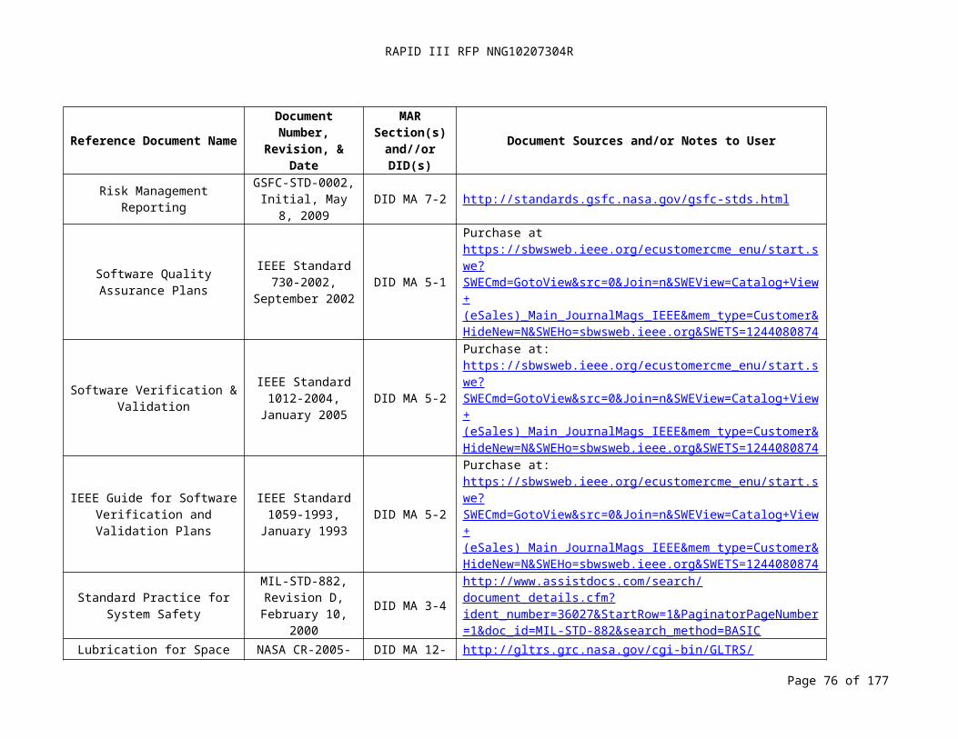
RAPID III RFP NNG10207304R
DID MA 3-6: OPERATING AND SUPPORT HAZARD ANALYSIS (04-18-2008)
Title:Operating and Support Hazard Analysis (O&SHA)
DID No.:MA 3-6
Reference:MAR Paragraph 3.2.2.3
Use:The Operating & Support Hazard Analysis (O&SHA) addresses the implementation of safety requirements for personnel, procedures, and equipment used during testing, transportation, storage, and integration operations at the launch site.
Related Documents:- AFSPCMAN 91-710, Range Safety User Requirements Manual- NPR 8715.3, NASA General Safety Program Requirements
Place/Time/Purpose of Delivery:Deliver to the Project Office as a part of the MSPSP (DID MA 3-7) for approval.
Preparation Information: The Contractor shall perform and document an operating and support hazard analysis (O&SHA) to examine procedurally controlled activities. The O&SHA shall: evaluate activities for hazards or risks introduced into the system by operational and support procedures, evaluate the adequacy of operational and support procedures used to eliminate, control, or abate identified hazards or risks, identify and evaluate hazards resulting from the implementation of operations or tasks performed by persons. It shall consider the following criteria: the planned system configuration and/or state at each phase of activity; the facility interfaces; the planned environments or the ranges thereof; the supporting tools or other equipment, including software controlled automatic test equipment, specified for use; operational and/or task sequence, concurrent task effects and limitations; biotechnological factors, regulatory or contractually specified personnel safety and health requirements; and the potential for unplanned events including hazards introduced by human errors. The human shall be considered an element of the total system, receiving both inputs and initiating outputs during the conduct of this analysis. The O&SHA shall identify the safety requirements or alternatives needed to eliminate or control identified hazards or to reduce the associated risk to a level that is acceptable under either regulatory or Range Safety specified criteria. The O&SHA shall indicate the need for revised tailoring of some requirements of this publication depending on the level of risk identified or the discovery of any previously unidentified hazards. The analysis shall identify the following:
- Activities that occur under hazardous conditions, their time periods, and the actions required to minimize risk during these activities and time periods
- Changes needed in functional or design requirements for system hardware and software, facilities, tooling, or support and test equipment to eliminate or control hazards or reduce associated risks.
- Requirements for safety devices and equipment, including personnel safety and life support equipment.
Page 76 of 126
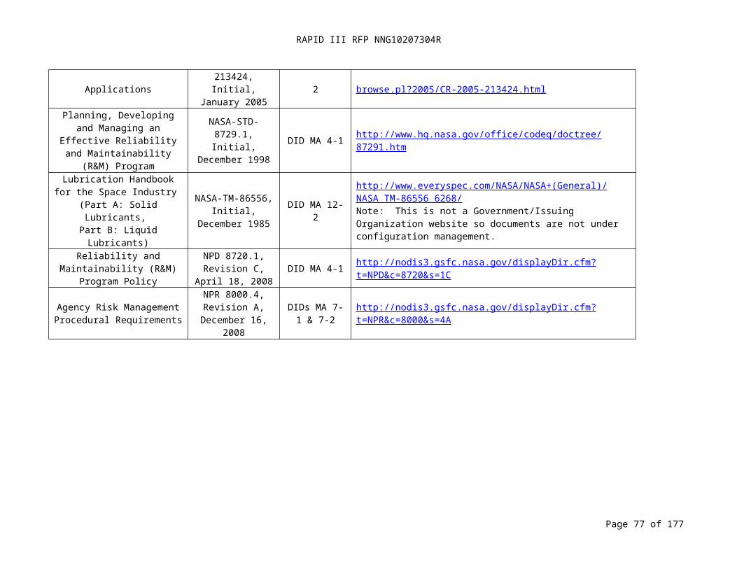
RAPID III RFP NNG10207304R
DID MA 3-6: OPERATING AND SUPPORT HAZARD ANALYSIS (04-18-2008) (CONTINUED)
- Warnings, cautions, and special emergency procedures such as egress, rescue, escape, render safe, explosive ordnance disposal, and backout, including those necessitated by failure of a computer software-controlled operation to produce the expected and required safe result or indication.
- Requirements for packaging, handling, storage, transportation, maintenance, and disposal of hazardous materials.
- Requirements for safety training and personnel certification.- Effects of non-developmental hardware and software across the interface with other
system components or subsystems.- Potentially hazardous system states under operator control.- Assessment of Procedures. The O&SHA shall document system safety assessment of
procedures involved in system production, deployment, installation, assembly, test, operation, maintenance, servicing, transportation, storage, modification, demilitarization, and disposal.
Page 77 of 126

RAPID III RFP NNG10207304R
DID MA 3-7: MISSILE SYSTEM PRE-LAUNCH SAFETY PACKAGE (08-29-2008)
Title: Missile System Pre-launch Safety Package (MSPSP)
DID No.:MA 3-7
Reference:
MAR Paragraph 3.2.3Use:
The MSPSP provides a description of the payload design to support hazard analysis results, hazard analysis method, and other applicable safety related information. The Contractor shall include analyses identifying the ground operations hazards associated with the flight system, ground support equipment, and their interfaces. The Contractor shall take measures to control or minimize hazards. In addition to identifying hazards, the MSPSP documents controls and verification methods for each hazard in a Hazard Report. The analysis shall be updated as the hardware progresses through design, fabrication, and test. A list of hazardous/toxic materials with material safety data sheets and a description of the hazardous and safety critical operations associated with the payload shall be included in the final MSPSP.The safety assessment shall begin early in the program formulation process and continue throughout all phases of the mission lifecycle. The spacecraft or instrument Project Manager shall demonstrate compliance with these requirements and shall certify to GSFC and the launch range, through the MSPSP, that all safety requirements have been met.
Related Documents: - AFSPCMAN 91-710, Range Safety User Requirements Manual (as applicable)
Place/Time/Purpose of Delivery:- Deliver the Preliminary MSPSP to the Project Office thirty (30) days after Mission
PDR for approval.- Deliver the Intermediate MSPSP to the Project Office thirty (30) days prior to Mission
Critical Design Review (CDR) for approval.- Deliver the Final MSPSP to the Project Office sixty (60) days prior to Spacecraft/
Observatory shipment to Launch Range for approval.- Deliver the Final MSPSP to the Range Safety within ten (10) days after approval by
the Project Office for approval.NOTE: The Preliminary MSPSP delivery shall include necessary launch range safety requirements tailoring. See applicable launch range and launch vehicle requirements for details.Preparation Information:
1. Introduction. State the purpose of the safety data package.2. System Description. This Paragraph may be developed by referencing other program
documentation such as technical manuals, System Program Plan, System Specification.3. System Operations.
a. A description of the procedures for operating, testing, and maintaining the system, including the safety features and controls.
b. A description of special safety procedures needed to assure safe operations, test and maintenance, including emergency procedures.
c. A description of anticipated operating environments and specific operator skills.
Page 78 of 126

RAPID III RFP NNG10207304R
DID MA 3-7: MISSILE SYSTEM PRELAUNCH SAFETY PACKAGE (08-29-2008) (CONTINUED)
d. A description of special facility requirements or personal equipment to support the system.
4. Systems Safety Engineering Assessment . This Paragraph shall include:a. A summary of the criteria and methodology for classifying and ranking hazardous
conditions.b. A description of the analyses and tests performed to identify inherent hazardous
conditions, including the software safety analysis.c. Hazard Reports by subsystem or major component level.
i. A discussion of the actions taken to eliminate or control these items. ii. A discussion of the effects of these controls on the probability of occurrence
and severity level of potential mishaps. iii. A discussion of the residual risks that remain after the controls are applied or
for which no controls could be applied. iv. A discussion of the results of tests conducted to validate safety criteria
requirements and analyses (these items should appear in the Verification Tracking Log).
5. Conclusions and Recommendations. This Paragraph shall include:a. An assessment of the results of the safety program efforts; a list of significant
hazards and specific safety recommendations to ensure the safety of personnel and property.
b. For hazardous materials: (1) Material identification as to type, quantity, and hazards.(2) Safety precautions and procedures for use, storage, transportation, and disposal.(3) A copy of the Material Safety Data Sheet (OSHA Form 20 or DD Form 1813).
c. Appropriate radiation forms/analysis.d. Reference material to include a list of all pertinent references such as Test Reports,
Preliminary Operating Manuals and Maintenance Manuals.e. Recommendations applicable to the safe interface of this system with the other
system(s).f. A statement signed by the Contractor’s System Safety Manager and Program
Manager certifying that all identified hazards have been eliminated or controlled and that the system is ready to test, operate, or proceed to the next mission phase.
Page 79 of 126
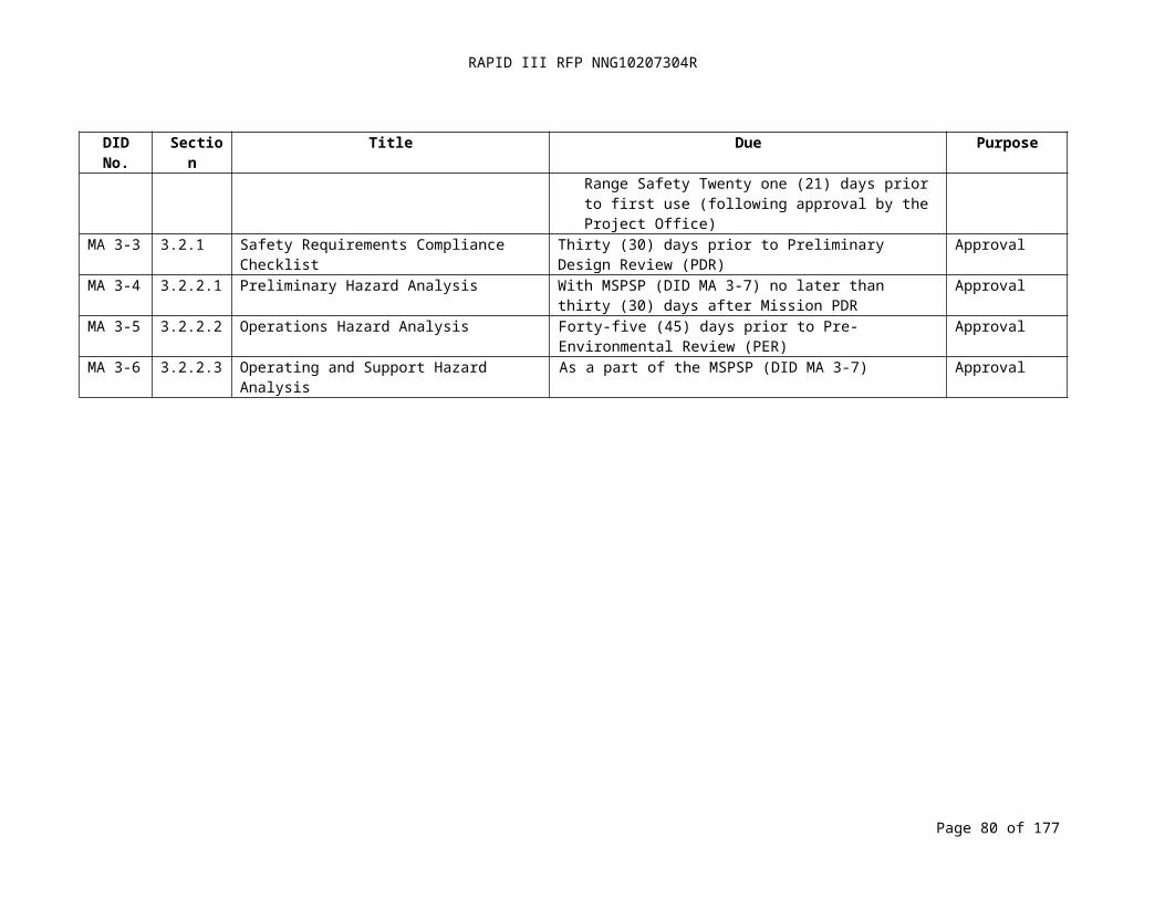
RAPID III RFP NNG10207304R
DID MA 3-8: VERIFICATION TRACKING LOG (07-15-2008)
Title: Verification Tracking Log
DID No.: MA 3-8
Reference: MAR Paragraph 3.2.4
Use: Provides documentation of a Hazard Control and Verification Tracking process as a closed-loop system to ensure that safety compliance has been satisfied in accordance to applicable launch range safety requirements.
Related Documents: - AFSPCMAN 91-710, Range Safety User Requirements Manual (as applicable)
Place/Time/Purpose of Delivery:- Deliver the Verification Tracking Log (VTL), identifying hazard controls that are not
verified as closed, to the Project Office with the final MSPSP DID (MA 3-7) for review. - After the Pre-Ship Review (PSR), deliver VTL updates to the Project Office weekly for
review until all hazard controls are verified as closed.Note: The Contractor shall close items with the appropriate rationale prior to first operational use or restraint.
Preparation Information:The VTL provides documentation that demonstrates the process of verifying the control of all hazards by test, analysis, inspection, similarity to previously qualified hardware, or any combination of these activities. All verifications that are listed on the hazard reports shall reference the tests/analyses/inspections. Results of these tests/analyses/inspections shall be available for review and submitted in accordance with the contract schedule and applicable launch site range safety requirements.
The VTL shall contain the following information in tabular format:- Hazard Report Number. - Safety Verification Number. - Description (Identify procedures/analyses by number and title). - Constraints on Launch Site Operations. - Independent Verification Required (e.g., mandatory inspection points).- Scheduled Completion Date. - Completion Date.- Method of Closure.
Page 80 of 126

RAPID III RFP NNG10207304R
DID MA 3-9: SAFETY VARIANCE (01-07-2009)
Title:Safety Variance
DID No.:MA 3-9
Reference:MAR Paragraph 3.2.5
Use:A Safety Variance documents a safety requirement that cannot be met and the rationale for approval of a waiver, exception, or deviation as defined in NPR 8715.3. Note: a variance may require Range Safety concurrence.
Related Documents (each as applicable):- AFSPCMAN 91-710, Range Safety User Requirements Manual- KNPR 8715.3, KSC Safety Practices Procedural Requirements- NPR 8715.3, NASA General Safety Program Requirements
Place/Time/Purpose of Delivery:- Deliver to the Project Office within thirty (30) days of identifying the need for a
variance for approval.
Preparation Information:The Contractor shall include the following information for the review of a variance request:- A statement of the specific safety requirement and its associated source document
name and paragraph number for which a variance is requested.- A technical justification for the variance.- Analyses to show the mishap potential of the proposed alternate requirement,
method, or process as evaluated against the specified requirement.- An assessment of the risk involved in accepting the variance; when it is determined
that there are no hazards, the basis for such determination should be provided.- A narrative on possible ways of reducing hazards severity and probability and
existing compliance activities.- Starting and expiration dates for variance, if applicable.
Page 81 of 126

RAPID III RFP NNG10207304R
DID MA 3-10: ORBITAL DEBRIS ASSESSMENT (07-15-2008)
Title:Orbital Debris Assessment
DID No.:MA 3-10
Reference:MAR Paragraph 3.2.6
Use:Ensure NASA requirements for post mission orbital debris control are met.
Related Documents:- NPR 8715.6A, NASA Procedural Requirements for Limiting Orbital Debris - NASA-STD-8719.14, Process for Limiting Orbital Debris
Place/Time/Purpose of Delivery:- Deliver preliminary package to the Project Office fifteen (15) days prior to mission PDR
for review.- Deliver final package to the Project Office sixty (60) days prior to mission CDR for
approval.- Deliver updates the final package to the Project Office for approval within thirty (30)
days of identification of design changes that affect the assessment.Preparation Information:
The assessment shall be done in accordance with NPR 8715.6A NASA Procedural Requirements for Limiting Orbital Debris and NASA-STD-8719.14 Process for Limiting Orbital Debris. The preliminary assessment is conducted to identify areas where the project may contribute debris and to assess this contribution relative to the guidelines. The final assessment conducted shall include comments on changes made since the preliminary assessment. The detail shall be consistent with the available information of design and operations. The Contractor shall submit updates to the final assessment for design changes after CDR that impact the potential for debris generation.
NOTE: Orbital Debris Assessment Software is available for download from Johnson Space Center at URL: http://sn-callisto.jsc.nasa.gov/mitigate/das/das.html
Page 82 of 126
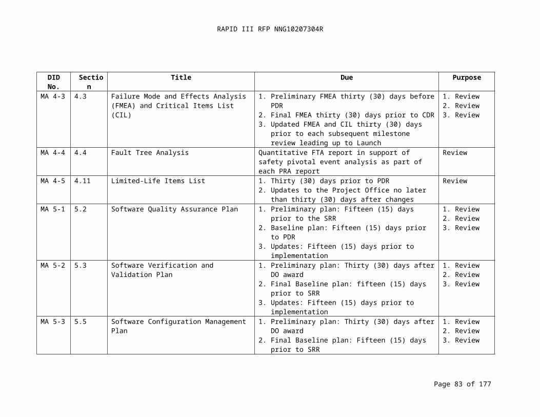
RAPID III RFP NNG10207304R
DID MA 3-11: MISHAP PREPAREDNESS AND CONTINGENCY PLAN (07-15-2008)
Title:Mishap Preparedness and Contingency Plan
DID No.:MA 3-11
Reference:MAR Paragraph 3.2.7
Use:Ensure that requirements for mishap reporting are met.
Related Documents:- NPR 8621.1, NASA Procedural Requirements for Mishap Reporting, Investigating,
and RecordkeepingPlace/Time/Purpose of Delivery:- Deliver to the Project Office thirty (30) days prior to mission PDR for review.
Preparation Information:The Contractor shall prepare a Mishap Preparedness and Contingency Plan per the requirements of NPR 8621.1
Page 83 of 126
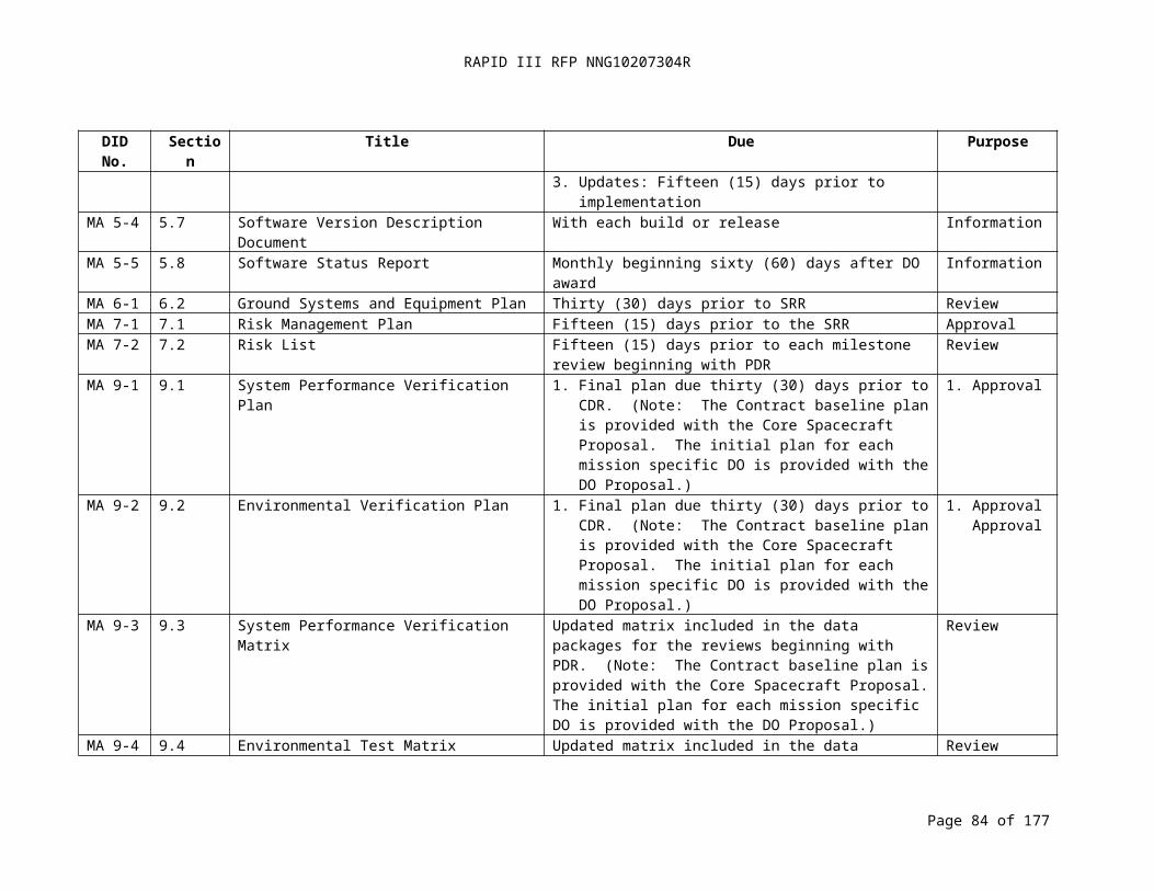
RAPID III RFP NNG10207304R
DID MA 3-12: MATERIAL SELECTION LIST FOR PLASTIC FILMS, FOAMS, AND ADHESIVE TAPES (11-04-2008)
Reference:MAR Paragraph 3.2.8
Use:Submitted to Launch Range Safety for assessment of flammability.
Related Documents:- KSC Form KTI-5212, Material Selection List for Plastic Films, Foams, and Adhesive
TapesPlace/Time/Purpose of Delivery:- Deliver to the Project Office with the Final MSPSP (DID MA 3-7) for review.
Preparation Information: The Contractor shall prepare the form per the requirements of related documents/forms.
(See Appendix C for form information.)
Page 84 of 126
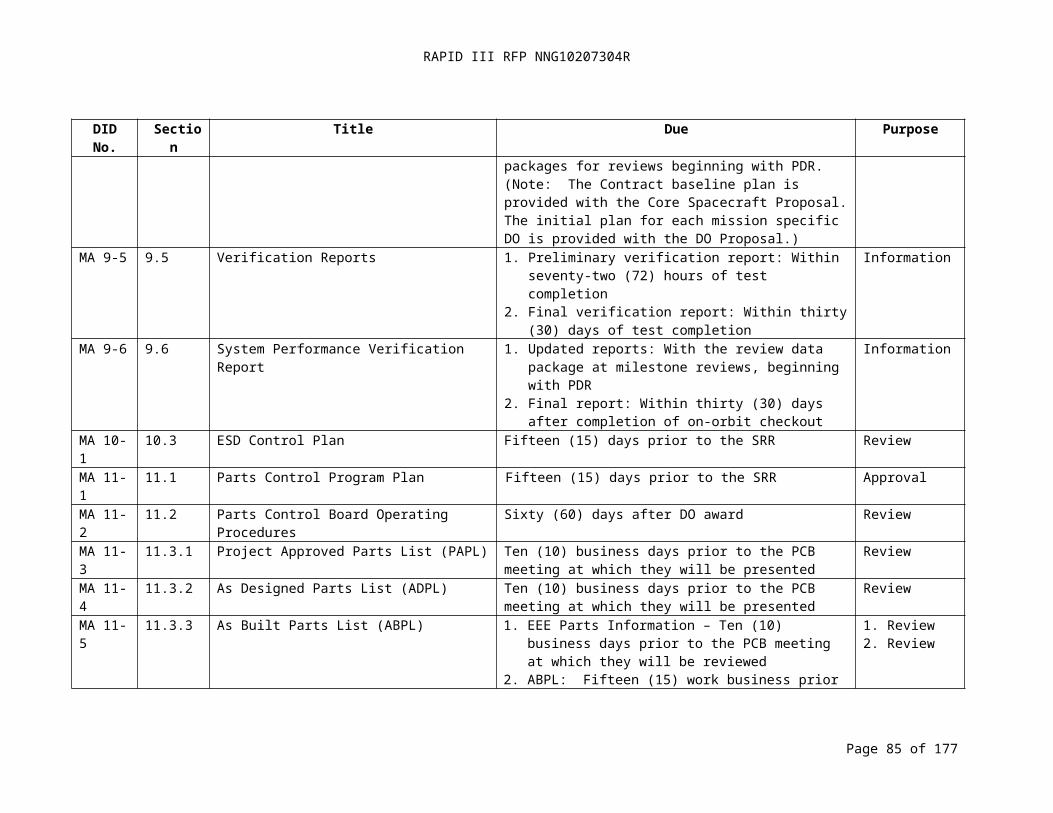
RAPID III RFP NNG10207304R
DID MA 3-13: RADIATION FORMS AND ANALYSES (11-04-2008)
Title:Radiation Forms and Analyses
DID No.:MA 3-13
Reference:MAR Paragraph 3.2.8
Use:The forms and analyses support the NASA launch safety approval process.
Related Documents:- KNPR 1860.1, KSC Ionizing Radiation Protection Program- KNPR 1860.2, KSC Non-Ionizing Radiation Protection Program- KSC Form 16-450 NS, Radiation Training & Experience Summary (Non-Ionizing
Radiation)- KSC Form 16-294 NS, Radiation Training & Experience Summary (Ionizing Radiation)- KSC Form 16-447, Laser Device Use Request/Authorization- KSC Form 16-451 NS, Radiofrequency/Microwave System Use Request/Authorization- KSC Form 16-295 NS, Radiation Use Request/Authorization (Radioactive Materials)
Place/Time/Purpose of Delivery:- Deliver to the Project Office with the Final MSPSP (DID MA 3-7) for review.
Preparation Information:The Contractor shall prepare the forms and analyses per the requirements of related documents/forms. (See Appendix C for form information.)
Page 85 of 126

RAPID III RFP NNG10207304R
DID MA 3-14: PROCESS WASTE QUESTIONNAIRE (10-31-2008)
Title:Process Waste Questionnaire
DID No.:MA 3-14
Reference:MAR Paragraph 3.2.8, MAR Appendix F
Use:The forms and analyses support the NASA launch safety approval process.
Related Documents:- KSC Form 26-551 V2, Process Waste Questionnaire
Place/Time/Purpose of Delivery:- Deliver to the Project Office with the Final MSPSP (DID MA 3-7) for review.
Preparation Information:The Contractor shall prepare the form and analyses per the requirements of related
document/form. (See Appendix C for form information.)
Page 86 of 126
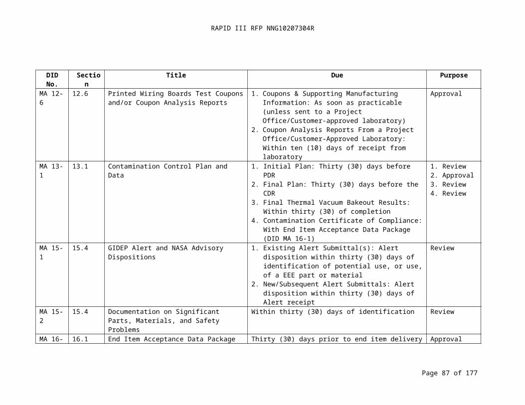
RAPID III RFP NNG10207304R
DID MA 3-15: ENVIRONMENTAL IMPACT STATEMENT (10-31-2008)
Title:Environmental Impact Statement
DID No.:MA 3-15
Reference:MAR Paragraph 3.2.8, MAR Appendix F
Use:The forms and analyses support the NASA launch safety approval process
Related Documents:- AF Form 813, Request for Environmental Impact Analysis
Place/Time/Purpose of Delivery:- Deliver to the Project Office with the Final MSPSP (DID MA 3-7) for review.
Preparation Information:The Contractor shall prepare the form and analyses per the requirements of related
document/form. (See Appendix C for form information.)
Page 87 of 126
RAPID III RFP NNG10207304R
DID MA 4-1: PROBABILISTIC RISK ASSESSMENT (PRA) AND RELIABILITY PROGRAM PLAN AND REPORTS (02-19-2009)
Title:Probabilistic Risk Assessment (PRA) and Reliability Program Plan and Reports
DID No.:MA 4-1
Reference:MAR Paragraph 4.1
Use:Planning and implementation of Probabilistic Risk Assessment (PRA) and reliability activities for safety critical functions.
Related Documents:- NASA Policy Directive (NPD) 8720.1, NASA Reliability and Maintainability (R&M)
Program Policy- NASA-STD-8729.1, Planning, Developing and Managing an Effective Reliability and
Maintainability (R&M) Program- NPR 8705.4, Risk Classification for NASA Payloads- NPR 8705.5, Probabilistic Risk Assessment (PRA) Procedures for NASA Programs and
Projects- NPR 8515.3, NASA General Safety Program Requirements
Place/Time/Purpose of Delivery:
- Deliver final plans to the Project Office fifteen (15) days prior to the Systems Requirements Review (SRR) for review.
- Deliver activity reports related to implementation of the plans at milestone reviews beginning with the SRR for review.
Note: Contractor may include PRA and Reliability Program Plan in the Project Level MAIP.
Preparation Information:The PRA and Reliability Program Plan shall include:- A discussion of how the Contractor intends to implement and comply with PRA and
Reliability program requirements.- Charts and statements describing organizational responsibilities and functions
conducting each task to be performed as part of the Program. - A summary (matrix or other brief form) that indicates for each requirement, the
organization responsible for implementing and generating the necessary documents. - Identify the approval, oversight, or review authority for each task. - Narrative descriptions, time or milestone schedules, and supporting documents
describing the execution and management plan for each task. - Documentation, methods, procedures, and reporting specific to each task in the plan.
Page 88 of 126

RAPID III RFP NNG10207304R
DID MA 4-2: PROBABILISTIC RISK ASSESSMENT (02-19-2009)
Title:
Probabilistic Risk Assessment
DID No.:
MA 4-2Reference:
MAR Paragraph 4.2Use:
To provide a structured and disciplined approach to: analyzing system risk; supporting management decisions; improving safety, operations, performing maintenance and upgrades; improving performance; and reducing cost for safety critical items only.
Related Documents
- NPR 8705.4, Risk Classification for NASA Payloads- NPR 8705.5, Probabilistic Risk Assessment (PRA) Procedures for NASA Programs and
Projects- NPR 8715.3, NASA General Safety Program Requirements- PRA Procedures Guide for NASA Managers and Practitioners
Place/Time/Purpose of Delivery:
- Deliver interim report to the Project Office thirty (30) days prior to SRR for information.- Deliver updated interim report to the Project Office thirty (30) days prior to CDR for
review.- Deliver updated interim report to the Project Office thirty (30) days prior to Mission
Operations Review (MOR) for review.- Deliver final report to the Project Office thirty (30) days prior to Flight Operations
Review (FOR) for reviewPreparation Information:
The PRA shall be performed in accordance with NPR 8705.5 and include the following:- The objective and scope of the PRA for safety critical items only;- End-states-of-interest to the decision-maker;- Definition of the mission phases and success criteria;- Initiating event categories;- Top level scenarios;- Initiating and pivotal event models (e.g., fault trees and phenomenological event
models), including assessments of common cause failure modes;- Data development for probability calculations;- Integrated model and quantification to obtain risk estimates;- Assessment of uncertainties; and - Summary of results and conclusions, including a ranking of the lead contributors to risk.
Page 89 of 126

RAPID III RFP NNG10207304R
DID MA 4-3: FAILURE MODE AND EFFECTS ANALYSIS (FMEA) AND CRITICAL ITEMS LIST (CIL) (02-19-2009)
Title:
Failure Mode and Effects Analysis (FMEA) and Critical Items List (CIL)
DID No.:
MA 4-3
Reference:
MAR Paragraph 4.3Use:
Used to evaluate design against requirements, to identify single point failures and hazards, and to identify modes of failure within a system design for the early mitigation of potential safety critical functions only.
Related Documents
- GSFC Flight Assurance Procedure (FAP) P-322-208, Performing a Failure Mode and Effects Analysis
- NPR 8705.4, Risk Classification for NASA PayloadsPlace/Time/Purpose of Delivery:
- Deliver preliminary FMEA to the Project Office thirty (30) days before PDR for review.- Deliver final FMEA to the Project Office thirty (30) days prior to CDR for review.- Deliver updated FMEA and CIL to the Project Office thirty (30) days prior to each
subsequent milestone review leading up to Launch for review.Preparation Information:
The FMEA Report shall include the following:- A discussion of the approach of the analysis, methodologies, assumptions, results,
conclusions, and recommendations. - Objectives.- Level of the analysis.- Ground rules.- Functional description.- Functional block diagrams.- Reliability block diagrams.- Equipment analyzed.- Data sources used.- Problems identified.- Single-point failure analysis, to include the root cause, mitigation, and retention rationale
for those with severity categories 1, 1R, or 1S.- Corrective actions.- Work sheets identifying failure modes, causes, severity category, and effects at the item,
next higher level, and mission level, detection methods, and mitigating provisions.- CIL for severity categories 1, 1R, and 1S including item identification, cross-reference to
FMEA line items, and retention rationale. Appropriate retention rationale may include design features, historical performance, acceptance testing, manufacturing product assurance, elimination of undesirable failure modes, and failure detection methods.
Page 90 of 126

RAPID III RFP NNG10207304R
DID MA 4-4: FAULT TREE ANALYSIS (FTA) (02-19-2009)
Title:Fault Tree Analysis (FTA)
DID No.:MA 4-4
Reference:MAR Paragraphs 4.4
Use:Used to assess failure of safety critical functions from the top level perspective. Undesired top-level states are identified and combinations of lower-level events are considered to derive credible failure scenarios. The technique provides a methodical approach to identify events or environments that can adversely affect safety and provides an informed basis for assessing system risks.
Related Documents- NASA Fault Tree Handbook with Aerospace Applications - NPR 8705.4, Risk Classification for NASA Payloads- NPR 8715.3, NASA General Safety Program Requirements
Place/Time/Purpose of Delivery:- Deliver quantitative FTA report to Project Office in support of safety critical pivotal
event analysis as part of each PRA report for review.
Preparation Information:The mission FTA Report shall contain:- Analysis ground rules including definitions of undesirable end states;- References to documents and data used;- Fault tree diagrams; and- Results and conclusions.
Page 91 of 126
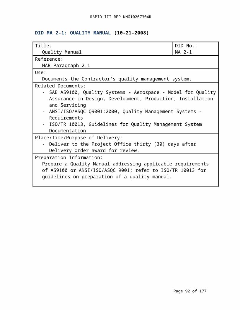
RAPID III RFP NNG10207304R
17.3
DID MA 4-5: LIMITED-LIFE ITEMS LIST (02-19-2009)
Title:Limited-Life Items List
DID No.:MA 4-5
Reference:MAR Paragraph 4.11
Use:Tracks the selection and application of limited-life items and the predicted impact on mission operations for safety critical functions only.
Related DocumentsNone
Place/Time/Purpose of Delivery:- Deliver Limited-Life Items List to the Project Office thirty (30) days prior to PDR for
review.- Deliver updates to the Project Office no later than thirty (30) days after changes are
made for review.Preparation Information:
The Contractor shall prepare and maintain a list of safety critical life-limited items and their predicted impact on mission operations. The list shall include expected life, required life, duty cycles, and rationale for selecting and using the item. The list may include such items as structures, thermal control surfaces, solar arrays, electromechanical mechanisms, batteries, compressors, seals, bearings, valves, tape recorders, momentum wheels, gyros, actuators and scan devices. The environmental or application factors that may affect the items include such things as atomic oxygen, solar radiation, shelf-life, extreme temperatures, thermal cycling, wear and fatigue.
Page 92 of 126
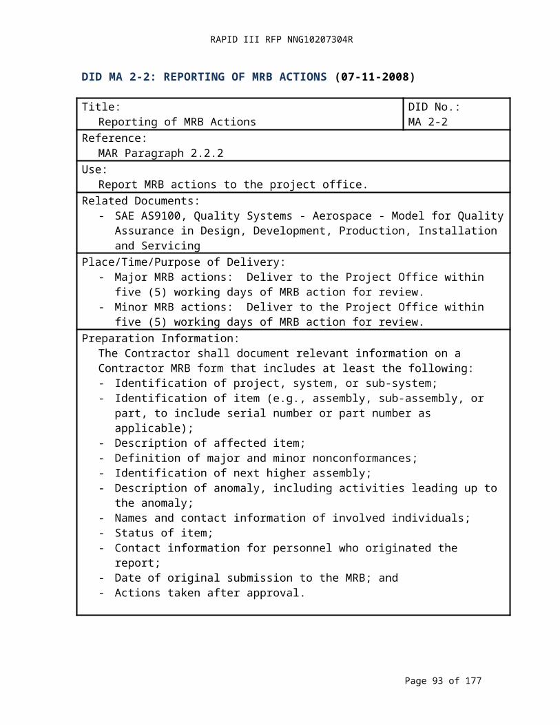
RAPID III RFP NNG10207304R
DID MA 5-1: SOFTWARE QUALITY ASSURANCE PLAN (04-23-2008)
Title:Software Quality Assurance Plan
DID No.:MA 5-1
Reference:MAR Paragraph 5.2
Use:Documents the Contractor’s Software Quality Assurance roles and responsibilities, surveillance activities, supplier controls, record collection, maintenance and retention, training, and risk management.
Related Documents:- Institute of Electrical and Electronics Engineers (IEEE) Standard 730-2002, Software
Quality Assurance Plans- NASA-STD-8739.8, NASA Standard for Software Assurance
Place/Time/Purpose of Delivery:- Deliver preliminary plan to the Project Office fifteen (15) days prior to the SRR for
review.- Deliver baseline plan to the Project Office fifteen (15) days prior to PDR for review.- Deliver updates to the Project Office fifteen (15) days prior to implementation for
review.Preparation Information:
The Software Quality Assurance Plan (SQAP) shall contain the following:- Purpose;- Reference documents and definitions;- Management;- Documentation;- Standards, practices, conventions, and metrics;- Software Reviews;- Test;- Problem Reporting and Corrective Action;- Tools, techniques, and methodologies;- Media control;- Supplier control;- Records, collection, maintenance, and retention;- Training;- Risk Management; and- SQAP Change procedure and history.
Page 93 of 126

RAPID III RFP NNG10207304R
DID MA 5-2: SOFTWARE VERIFICATION & VALIDATION PLAN (07-11-2008)
Title:Software Verification & Validation Plan
DID No.:MA 5-2
Reference:MAR Paragraph 5.3
Use:Documents the software V&V process which determines whether the development products of a given activity conform to the requirements of that activity and whether the software satisfies its intended use and user needs. This determination may include analysis, evaluation, review, inspection, assessment, and testing of the software products and processes. The V&V process shall be performed in parallel with the software development, not at the conclusion of the development effort.
Related Documents:- NPR 7150.2, NASA Software Engineering Requirements- IEEE Standard 1012-2004, IEEE Standard for Software Verification and Validation- NASA-STD-8739.8, NASA Standard for Software Assurance - IEEE Standard 1059-1993, IEEE Guide for Software Verification and Validation Plans
Place/Time/Purpose of Delivery:- Deliver preliminary plan to Project Office thirty (30) days after DO Award for review.- Deliver baseline plan to Project Office fifteen (15) days prior to SRR for review.- Provide updates to Project Office fifteen (15) days prior to implementation for review.
Preparation information: Purpose- Referenced documents.- Definitions.- V&V Overview:
o Organization;o Master Schedule;o Software integrity level scheme;o Resource summary;o Responsibilities; ando Tools, techniques, and methods.
- V&V Processes:o Process: Management;
Activity: Management of V&V;o Process: Acquisition;
Activity: Acquisition of support V&V;o Process: Supply;
Activity: Planning V&V;o Process: Development;
Activity: Concept V&V; Activity: Requirements V&V; Activity: Design V&V; Activity: Implementation V&V; Activity: Test V&V;
Page 94 of 126
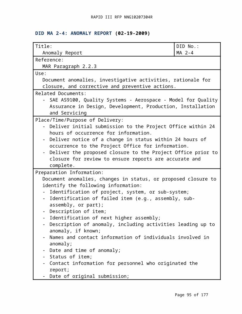
RAPID III RFP NNG10207304R
Activity: Installation and Checkout V&V;
DID MA 5-2: SOFTWARE VERIFICATION & VALIDATION PLAN (CONTINUED)
o Process: Operations; Activity: Operations V&V;
o Process: Maintenance; and Activity: Maintenance V&V.
- V&V Reporting Requirements:o Tasks reports;o Activity: summary reports;o Anomaly reports;o V&V final reports;o Special studies reports (optional); ando Other reports (optional).
- V&V Administrative requirements:o Anomaly resolution and reporting;o Task iteration policy;o Deviation policy;o Control procedures; ando Standards, practices, and conventions.
- V&V test documentation requirements.
Page 95 of 126
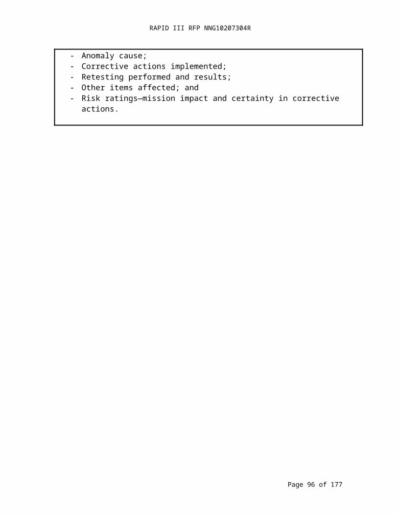
RAPID III RFP NNG10207304R
DID MA 5-3: SOFTWARE CONFIGURATION MANAGEMENT PLAN (05-29-2008)
Title:Software Configuration Management Plan
DID No.:MA 5-3
Reference:MAR Paragraph 5.5
Use:The purpose of the Software Configuration Management Plan is to define the software configuration management system, roles and responsibilities, activities, schedules, resources, and plan maintenance.
Related Documents:- ANSI-IEEE Standard 828-2005, IEEE Standard for Software Configuration
Management Plans- ANSI-IEEE Standard 1042-1987, IEEE Guide to Software Configuration Management- NPR 7150.2, NASA Software Engineering Requirements
Place/Time/Purpose of Delivery:- Deliver preliminary plan to the Project Office thirty (30) days after DO award for
review.- Deliver baseline plan to the Project Office fifteen (15) days prior to SRR for review.- Deliver updates to the plan to the Project Office fifteen (15) days prior to
implementation for review. Preparation Information:The Contractor shall develop, maintain, manage, and implement a Software Configuration Management (SCM) system that provides baseline management and control of software requirements, design, source code, data, and documentation. The SCM system shall be applied to all deliverables and designated non-deliverable software products. The Contractor shall document the SCM system, and associated tools, within the plan. The plan shall address configuration identification, configuration control, configuration status accounting, and configuration audits and reviews.
As part of SCM, the Contractor shall employ a source code version control tool (e.g., ClearCase, Starbase) that allows Contractors to check in/checkout current or previous versions of a source file. The Contractor shall also use a requirements management tool (e.g., DOORS) to manage the software requirements baseline. The Contractor shall document and implement a process for Software Problem Reporting and Corrective Action that addresses reporting, analyzing, and tracking software non-conformances throughout the development lifecycle. Software Problem Reporting can be included as part of Contractor’s overall project Problem Reporting and Corrective Action Plan.
The Software Configuration Management (SCM) Plan shall include/address:- Introduction – Purpose, scope, definitions and references.- SCM Management Overview – Organization, responsibilities, and interfaces and
relationships to software life cycle.- Software Configuration Management Activities: 1) Configuration Identification, 2)
Configuration Control, 3) Configuration Status Accounting, 4) Configuration Audits, 5) Interface Control, 6) Subcontractor control.
Page 96 of 126

RAPID III RFP NNG10207304R
DID MA 5-3: SOFTWARE CONFIGURATION MANAGEMENT PLAN (CONTINUED)
- Software Configuration Management Schedules.- Software Configuration Management Resources – tools, techniques, equipment,
personnel, and training.- Software Configuration Management Plan Maintenance.
Note: SCM Plan may be contained in Contractor Project CM Plan or Software Management Plan.
Page 97 of 126
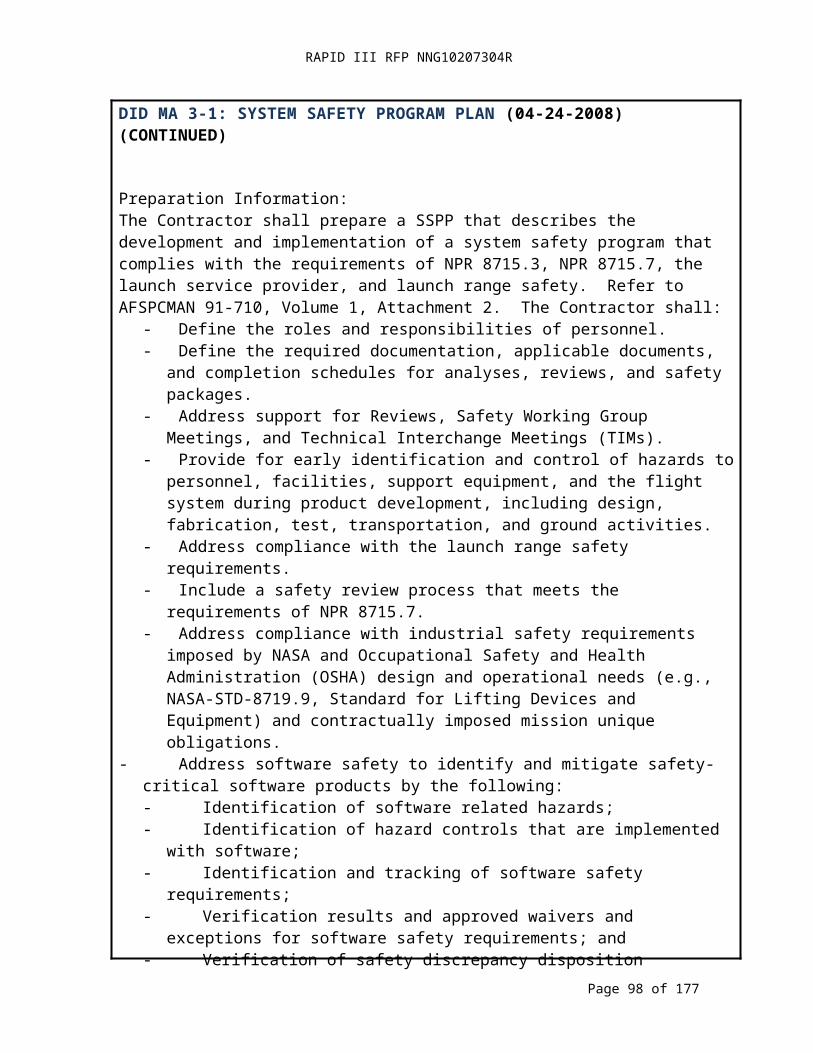
RAPID III RFP NNG10207304R
DID MA 5-4: SOFTWARE VERSION DESCRIPTION DOCUMENT (01-09-2009)
Title:Software Version Description Document (VDD)
DID No.:MA 5-4
Reference:MAR Paragraph 5.7
Use:A Version Description Document (VDD) shall be the primary configuration control document used to track and control versions of software released to testing, implementation, or the final operational environment. The VDD identifies and documents the version of the computer software configuration items (CSCI’s) and other deliverables that comprise the software build or release, including changes since the last VDD was issued.
Related Documents:- NPR 7150.2, NASA Software Engineering Requirements, Section 5.2.8
Place/Time/Purpose of Delivery:- Deliver to the Project Office with each build or release for information.
Preparation Information:The Version Description Document shall include/address:
- Established Baseline – identifies the delivered system and software (e.g., type, version numbers, release numbers, date, and location).
- New Features and/or Requirements Implemented and Delivered. - Planned Features Absent from this version.- List of Outstanding Change Requests (CRs), Discrepancy Reports (DRs), and
workarounds (if applicable) against this release.- List of CRs and DR’s implemented since the previous version.- Any Significant Changes in Operations.- Applicable Documents associated with this release (e.g., user guides).- Installation instructions on how to build the system (including tools, operating
systems, assemblers, compilers, libraries, existing software, data files, and delivered software). Note: All version numbers shall be provided.
- Information from any Configuration Audits performed prior to the delivery (to ensure that the correct versions were delivered with the correct functionality).
Page 98 of 126
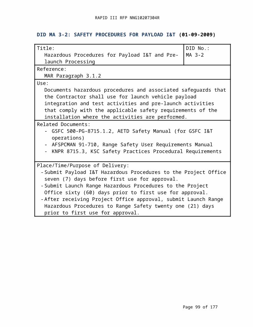
RAPID III RFP NNG10207304R
DID MA 5-5: SOFTWARE STATUS REPORT (01-09-2009)
Title:Software Status Report
DID No.:MA 5-5
Reference:MAR Paragraph 5.8
Use:Software Assurance Status Report provides information regarding current status and future activities.
Related Documents:- ANSI-IEEE Standard 828-2005, IEEE Standard for Software Configuration
Management Plans- ANSI-IEEE Standard 1042-1987, Guide to Software Configuration Management- NPR 7150.2, NASA Software Engineering Requirements
Place/Time/Purpose of Delivery:- Deliver to Project Office monthly beginning sixty (60) days after DO award for
information.
Preparation Information:As part of the Project Monthly Status Reports, the Contractor shall include the following software assurance activities: - Organization and key personnel changes.- Assurance accomplishments and resulting software assurance metrics (e.g., for
activities such as inspection and test, reviews, contractor/subcontractor surveys, and audits).
- Subcontractor assurance accomplishments.- Trends in software quality metric data (e.g., total number of software problem reports,
including the number of problem reports that were opened and closed in that reporting period).
- Significant problems or issues.- Plans for upcoming software assurance activities.- Lessons Learned.
Page 99 of 126
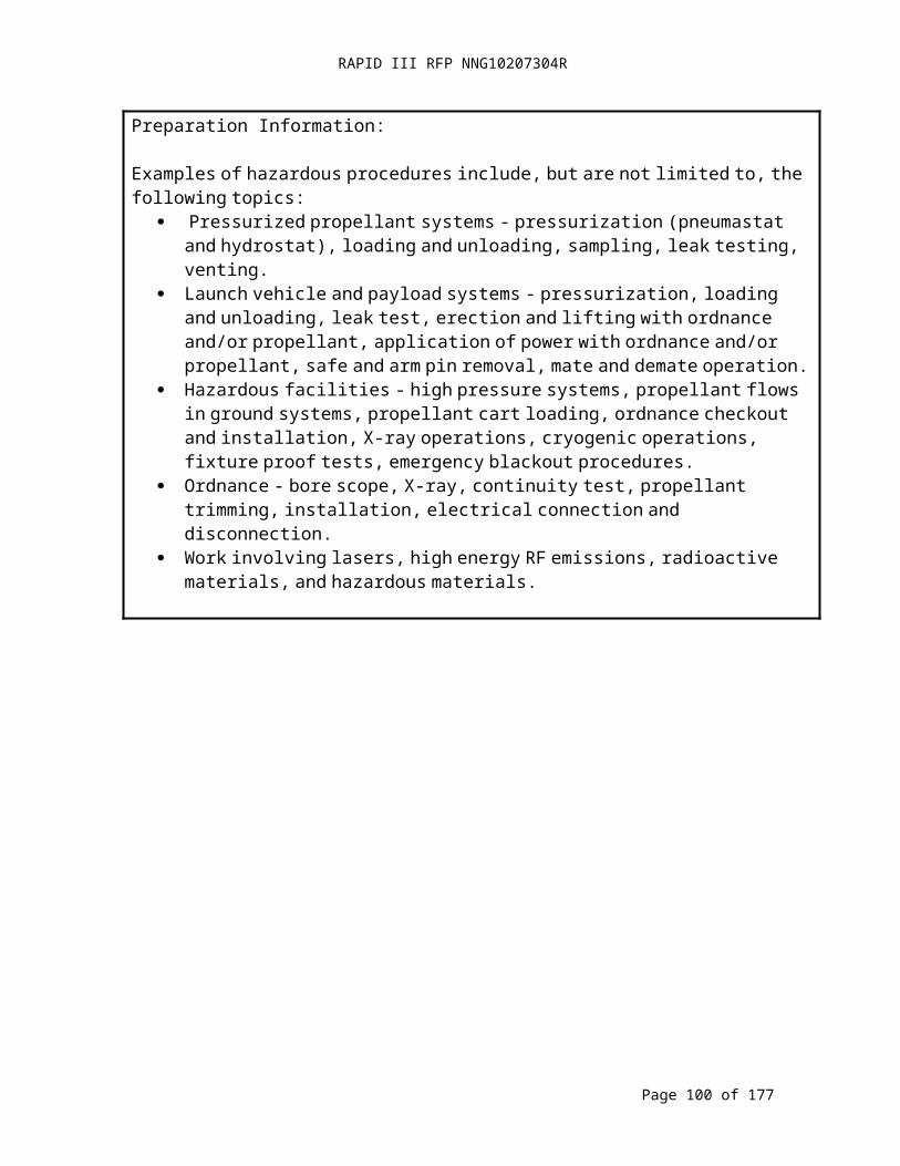
RAPID III RFP NNG10207304R
DID 6-1: GROUND SYSTEMS AND EQUIPMENT (02-18-2009)
Title:Ground Systems and Equipment Plan
DID No.:MA 6-1
Reference:MAR Paragraph 6.1
Use:Documents the Contractor's plan for ground support equipment that will be used in the development of ground operations equipment and flight items.
Related Documents:- NASA-STD-8719.9 Standard for Lifting Devices and Equipment- GSFC-STD-1000 Rules for the Design, Development, Verification, and Operation of
Flight SystemsPlace/Time/Purpose of Delivery:- Deliver to the Project Office thirty (30) days prior to SRR for approval.
Preparation Information:
The Contractor’s plan shall address the ground systems and equipment requirements with respect to procurement, development, test, operation, and maintenance for both ground systems and flight systems. The plan shall address support to flight items to the extent necessary to assure functional integrity of flight items, including health and safety.
The Contractor shall document a plan that:- Identifies GSE functions necessary to develop and test flight and ground operations
items- Develops and builds the GSE
The program shall address:- Requirements definition, management, traceability, and verification.- Verification and validation.- Acceptance criteria for testing.- Configuration control (functional and physical).- Interface control drawings.- Critical Interfaces.- Testing.- User/operational manuals.- Mechanical stress analysis.- Items that directly interface with flight items and are required to be built and
maintained to the same standards.- Analyses required preventing induced damage to flight items.
Page 100 of 126
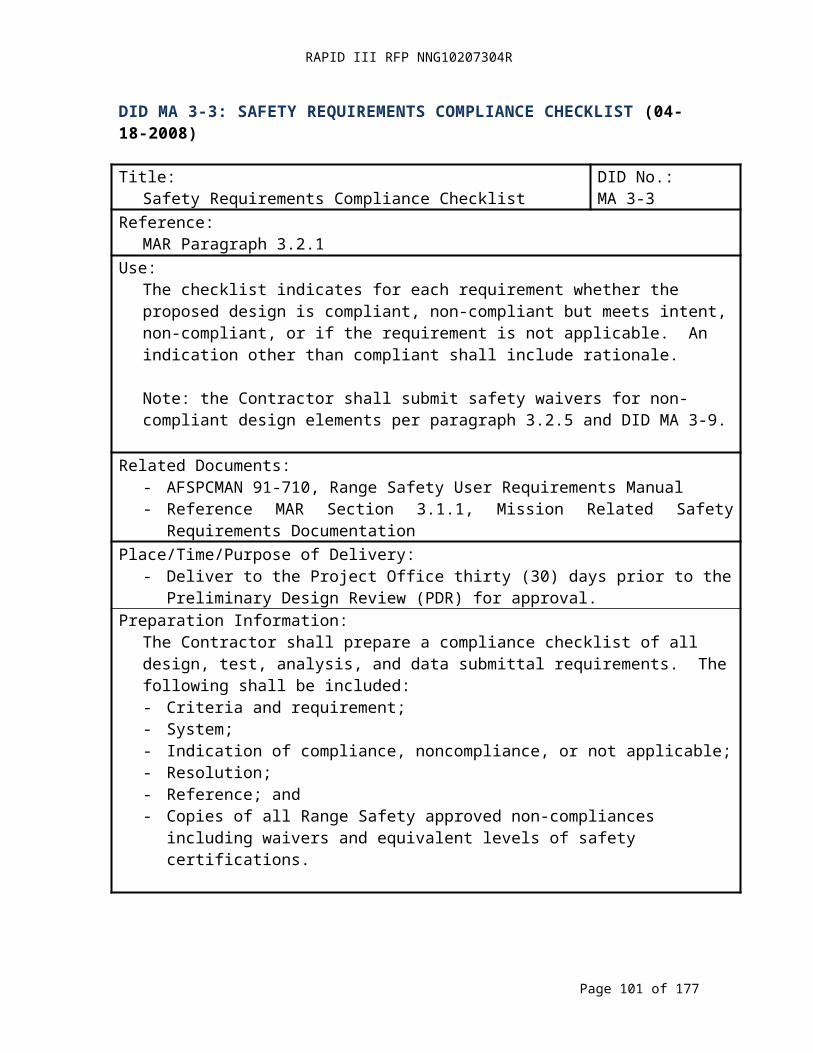
RAPID III RFP NNG10207304R
DID MA 7-1: RISK MANAGEMENT PLAN (04-18-2008)
Title:Risk Management Plan
DID No.:MA 7-1
Reference:MAR Paragraph 7.1
Use:Defines the process by which the Contractor identifies, evaluates, and mitigates the risks associated with program, project, and/or mission goals
Related Documents:- NPR 8000.4, Agency Risk Management Procedures and Guidelines
Place/Time/Purpose of Delivery:- Deliver to the Project Office fifteen (15) after contract award for approval.
Preparation Information:The Risk Management Plan shall include:- Description of contract requirements.- Purpose and Scope.- Assumptions, Constraints, and Policies.- Related Documents and Standards.- Risk Management Process Summary (Philosophy, Integration).- Risk Management Organization:
- Roles and Responsibilities;- Risk Management Review Board;- Standard Practices; and- Communication.
- Risk Attributes that will be used to classify risks;- As a minimum attributes shall be defined for safety, cost, schedule, and technical or
performance areas.- Risk buy-down chart (waterfall chart).- Criteria for prioritization of risks.- Mitigation plan content.- Process Details:
- Baselines;- Database (Use, Access, Updates, Responsibilities, etc.);- Identifying Risks;- Analyzing Risks;- Planning, Actions;- Tracking (metrics and their use);- Control; and- Documentation and Reporting.
Page 101 of 126
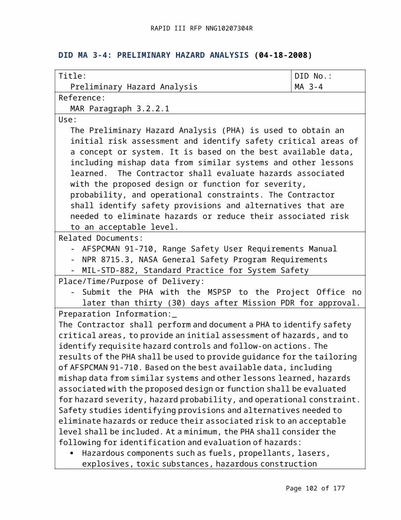
RAPID III RFP NNG10207304R
DID MA 7-2: RISK LIST (04-18-2008)
Title:Risk List
DID No.:MA 7-2
Reference:MAR Paragraph 7.2
Use:Defines the documentation and reporting of risk items.
Related Documents:- GSFC-STD-0002, Risk Management Reporting- NPR 8000.4, Agency Risk Management Procedural Requirements
Place/Time/Purpose of Delivery:- Deliver to the Project Office fifteen (15) days prior to each milestone review
beginning with PDR for reviewPreparation Information:
Prepare a prioritized list of risks that shall include:- Identification number;- Title;- Current approach (mitigate, watch, accept, research);- Rank; and- Trend.
Prepare a chart for each risk that includes:- Identification number;- Title;- Rank;- Risk statement (condition-consequence form);- Brief discussion of:- Current approach;- Actions causing change; and- Current status.
Page 102 of 126
RAPID III RFP NNG10207304R
DID MA 9-1: SYSTEM PERFORMANCE VERIFICATION PLAN (04-18-2008)
Title:System Performance Verification Plan
DID No.:MA 9-1
Reference:MAR Paragraph 9.1
Use:Establishes the System Performance Verification Plan.
Related Documents:- GSFC-STD-7000, General Environmental Verification Standard (GEVS) for GSFC
Flight Programs and ProjectsPlace/Time/Purpose of Delivery:
- Final plan due thirty (30) days prior to CDR for approval. (Note: The Contract baseline plan is provided with the Core Spacecraft Proposal. The initial plan for each mission specific DO is provided with the DO Proposal.)
Preparation Information:The System Performance Verification Plan shall be prepared to comply with the requirements of paragraph 2.1.1.1 of GSFC-STD-7000.
Page 103 of 126
RAPID III RFP NNG10207304R
DID MA 9-2: ENVIRONMENTAL VERIFICATION PLAN (04-18-2008)
Title:Environmental Verification Plan
DID No.:MA 9-2
Reference:MAR Paragraph 9.2
Use:Establishes the Environmental Verification Plan.
Related Documents:- GSFC-STD-7000 General Environmental Verification Standard (GEVS) for GSFC
Flight Programs and ProjectsPlace/Time/Purpose of Delivery:- Final plan due thirty (30) days prior to CDR for approval. (Note: The Contract
baseline plan is provided with the Core Spacecraft Proposal. The initial plan for each mission specific DO is provided with the DO Proposal.)
Preparation Information:The Environmental Verification Plan shall be prepared to comply with the requirements of paragraph 2.1.1.1.1 of GSFC-STD-7000.
Page 104 of 126
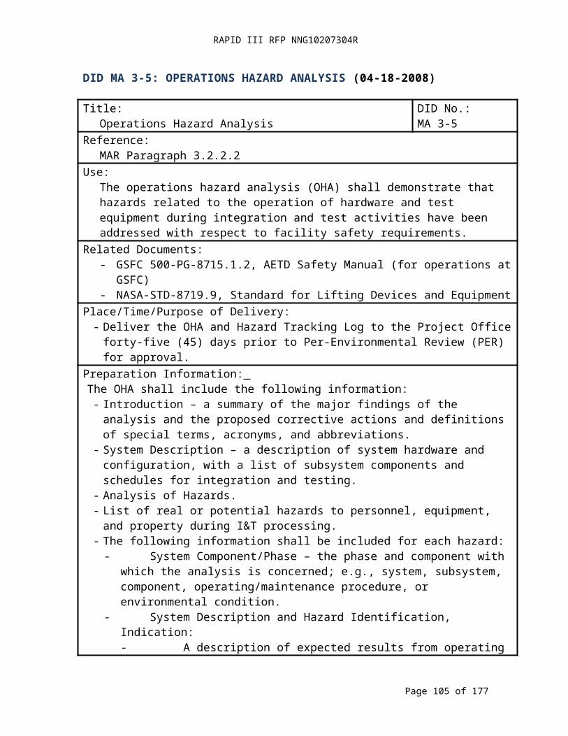
RAPID III RFP NNG10207304R
DID MA 9-3: SYSTEM PERFORMANCE VERIFICATION MATRIX (04-18-2008)
Title:System Performance Verification Matrix
DID No.:MA 9-3
Reference:MAR Paragraph 9.3
Use:Establishes the System Performance Verification Matrix.
Related Documents:- GSFC-STD-7000, General Environmental Verification Standard (GEVS) for GSFC
Flight Programs and ProjectsPlace/Time/Purpose of Delivery:- Deliver the updated Matrix in the data packages for reviews beginning with PDR
for review. (Note: The Contract baseline plan is provided with the Core Spacecraft Proposal. The initial plan for each mission specific DO is provided with the DO Proposal.)
Preparation Information:The System Performance Verification Matrix shall be prepared and maintained per the requirements of paragraph 2.1.1.2 of GSFC-STD-7000.
Page 105 of 126
RAPID III RFP NNG10207304R
DID MA 9-4: ENVIRONMENTAL TEST MATRIX (04-18-2008)
Title:Environmental Test Matrix
CDRL No.:MA 9-4
Reference:MAR Paragraph 9.4
Use:Establishes a matrix that summarizes the environmental tests and test status for flight hardware and other equipment.
Related Documents:- GSFC-STD-7000, General Environmental Verification Standard (GEVS) for GSFC
Flight Programs and ProjectsPlace/Time/Purpose of Delivery:
- Deliver the updated matrix in the review data package for reviews beginning with PDR for review. (Note: The Contract baseline plan is provided with the Core Spacecraft Proposal. The initial plan for each mission specific DO is provided with the DO Proposal.)
Preparation Information:Guidelines for environmental test matrices are in paragraph 2.1.1.2.1 of GSFC-STD-7000. An example of an environmental test matrix is given in Figure 2.1-1
Page 106 of 126

RAPID III RFP NNG10207304R
DID MA 9-5: VERIFICATION REPORTS (04-18-2008)
Title:Verification Reports
CDRL No.:MA 9-5
Reference:MAR Paragraph 9.5
Use:Establishes the requirement to submit Verification Reports.
Related Documents:- GSFC-STD-7000, General Environmental Verification Standard (GEVS) for GSFC
Flight Programs and ProjectsPlace/Time/Purpose of Delivery:
- Deliver preliminary verification report to Project Office within seventy-two (72) hours of test completion for information.
- Deliver final verification report = to Project Office within thirty (30) days of test completion for information.
Preparation Information:The Verification Reports shall be prepared to comply with the requirements of paragraph 2.1.1.5 of GSFC-STD-7000.
Page 107 of 126
RAPID III RFP NNG10207304R
DID MA 9-6: SYSTEM PERFORMANCE VERIFICATION REPORT (04-18-2008)
Title:System Performance Verification Report
CDRL No.:MA 9-6
Reference:MAR Paragraph 9.6
Use:Establishes a Performance Verification Report that compares hardware/software specifications with the final verified values.
Related Documents:- GSFC-STD-7000 General Environmental Verification Standard (GEVS) for GSFC
Flight Programs and ProjectsPlace/Time/Purpose of Delivery:- Deliver updated reports with the review data package at reviews beginning with PDR
for information.- Deliver the final report within thirty (30) days after completion of on-orbit checkout for
information.Preparation Information:
The System Performance Verification Report shall be prepared and maintained per paragraph 2.1.1.6 of GSFC-STD-7000.
Page 108 of 126
RAPID III RFP NNG10207304R
DID MA 10-1: ESD CONTROL PLAN (04-18-2008)
Title:ESD Control Plan
CDRL No.:MA 10-1
Reference:MAR Paragraph 10.3
Use:Implementation of an ESD control program at the Contractor’s and subcontractors’ facilities.
Related Documents:- ANSI/ESD S20.20, For the Development of an Electrostatic Discharge Control
Program for Protection of Electrical and Electronic Parts, Assemblies and Equipment (Excluding Electrically Initiated Explosive Devices)
Place/Time/Purpose of Delivery:Deliver plan to the Project Office fifteen (15) days prior to SRR for review.
Page 109 of 126

RAPID III RFP NNG10207304R
DID MA 11-1: PARTS CONTROL PROGRAM PLAN (02-19-2009)
Title:Parts Control Program Plan
DID No.:MA 11-1
Reference:MAR Paragraph 11.1
Use:Development and implementation of an EEE parts control program that addresses the system requirements for mission lifetime and reliability.
Related Documents- GSFC EEE-INST-002, Instructions for EEE Parts Selection, Screening,
Qualification, and Derating- S-311-M-70, Specification for Destructive Physical Analysis
Place/Time/Purpose of Delivery:- Deliver the PCP Plan to the Project Office fifteen (15) days after DO award for
approval.Preparation Information:
The PCP shall address the following:- Shelf life control plan;- Parts application derating;- Supplier and manufacturer surveillance;- ASICs, Gate Arrays, System-on-chip, Custom Integrated Circuits (ICs);- Radiation hardness assurance;- Handling, preservation, and packing;- Contamination control;- Traceability and lot control; and- Failure analysis.
Page 110 of 126

RAPID III RFP NNG10207304R
DID MA 11-2: PARTS CONTROL BOARD OPERATING PROCEDURES (02-13-2008)
Title:Parts Control Board Operating Procedures
DID No.:MA 11-2
Reference:MAR Paragraph 11.2
Use:Organization and operation of the Parts Control Board regarding the implementation of the Parts Control Program.
Related Documents- Parts Control Program Plan (DID MA 11-1)
Place/Time/Purpose of Delivery:Deliver the Parts Control Board operating procedures to the Project Office thirty (30) days after DO award for review.
Preparation Information:The Contractor shall address the following in the Parts Control Board procedures:- Organization and membership;- Meeting schedule;- Meeting notices;- Distribution of meeting agenda, notes, and minutes; and- Review and approval responsibilities and processes.
Page 111 of 126
RAPID III RFP NNG10207304R
DID MA 11-3: PROJECT APPROVED PARTS, LIST (10-21-2008)
Title:Project Approved Parts List (PAPL)
DID No.: MA 11-3
Reference:MAR Paragraph 11.3.1
Use:A list of EEE parts that are approved by the Parts Control Board for use in flight hardware.
Related Documents- Parts Control Program Plan (DID MA 11-1)
Place/Time/Purpose of Delivery:- Deliver EEE parts information to be added to the PAPL to the Parts Control Board
ten (10) business days prior to the PCB meeting at which the parts shall be presented for PCB approval. Deliver parts information to the Project Office for review.
Preparation Information:The PAPL shall contain the following information:- Flight component identity to the circuit board level;- Complete part number (i.e. DSCC part number, SCD part number, with all suffixes);- Manufacturer’s Generic Part number;- Manufacturer (not distributor);- Part Description (please include meaningful detail);- Federal Supplier Code (FSC);- Procurement Specification;- Comments and clarifications, as appropriate;- Quantity Required; - Procurement Part Number;- Flight Part Number (if different from the procurement part number);- Package Style/Designation;- Single Event Latch-up (SEL) Hardness/Tolerance and Data Source;- Single Event Upset (SEU) Hardness/Tolerance and Data Source;- Total Ionizing Dose (TID) Hardness/Tolerance and Data Source;- Displacement Damage Hardness/Tolerance and Data Source;- Proton Hardness/Tolerance and Data Source;- PCB Status;- PCB Approval Date;- PCB Required Testing/Evaluations; and- GIDEP Alert Information. (See DID MA 15-1.)
Page 112 of 126
RAPID III RFP NNG10207304R
DID MA 11-4: AS DESIGNED PARTS LIST (ADPL) (10-21-2008)
Title:As Designed Parts List (ADPL)
DID No.: MA 11-4
Reference:MAR Paragraph 11.3.2
Use:A list of EEE parts that are designed into in flight hardware.
Related Documents- Parts Control Program Plan (DID MA 11-1)
Place/Time/Purpose of Delivery:- Deliver EEE Parts information to be added to the ADPL to the Parts Control Board
ten (10) business days prior to the PCB meeting at which they shall be presented for PCB approval. Deliver parts information to the Project Office for review.
Preparation Information:The As Designed Parts List (ADPL) shall contain all PAPL fields plus the following information:- Assembly Name/Number;- Next Level of Assembly;- Need Quantity;- Reference Designator(s); and- Item number (if applicable).
Page 113 of 126

RAPID III RFP NNG10207304R
DID MA 11-5: AS BUILT PARTS LIST (ABPL) (02-19-2009)
Title:As Built Parts List (ABPL)
DID No.: MA 11-5
Reference:MAR Paragraph 11.3.3
Use:A list of EEE parts that are used in the flight hardware.
Related Documents- Parts Control Program Plan (DID MA 11-1)
Place/Time/Purpose of Delivery:1. Deliver information for EEE Parts to be added to the As Built Parts List to the Parts
Control Board ten (10) business days prior to the PCB meeting at which the parts shall be approved by the PCB. Deliver parts information to the Project Office for review.
2. Deliver the As Built Parts List to the Project Office fifteen (15) business days prior to the PSR for review.
Preparation Information:The As Built Parts List (ABPL): shall contain all ADPL fields plus the following minimum information:- Assembly serial number;- Next Level of Assembly serial number;- Lot/Date/Batch/Manufacturing Code, as applicable;- Manufacturer’s Commercial and Government Entity (CAGE) Code (specific plant
location preferred);- Distributor/supplier, if applicable; and- Part serial number, if applicable.
Page 114 of 126

RAPID III RFP NNG10207304R
DID MA 12-1: MATERIALS AND PROCESSES SELECTION, IMPLEMENTATION, & CONTROL PLAN (02-19-2009)
Title:Materials and Processes Selection, Implementation, & Control Plan
DID No.:MA 12-1
Reference:MAR Paragraph 12.1
Use:Defines the implementation of NASA-STD-6016 with the prescribed changes.
Related Documents:NASA-STD-6016, Standard Materials and Processes Requirement for Spacecraft
Place/Time/Purpose of Delivery:- Deliver to the Project Office 15 (15) days prior to the SRR for approval.
Preparation Information:For each paragraph in Paragraphs 4 and 5 of NASA-STD-6016 with the prescribed changes, the plan shall state the requirement from NASA-STD-6016, identify the degree of conformance under the subheading "Degree of Conformance," and identify the method of implementation under the subheading "Method of Implementation."
The plan shall address the following:- Conformance to the requirements of NASA-STD-6016 with the prescribed changes
and describe the method of implementation.- Organizational authority and responsibility for review and approval of Materials
and Processes (M&P) specified prior to release of engineering documentation.- Identification and documentation of Materials and Processes.- Procedures and data documentation for proposed test programs to support materials
screening and verification testing.- Materials Usage Agreement (MUA) Procedures.- Determination of material design properties, including statistical approaches to be
employed.- Identification of process specifications used to implement requirements in NASA-
STD-6016.
Robotic Missions- In paragraph 4.1.2, the Contractor may use GFSC forms or the Contractor’s equivalent
forms in lieu of the Materials and Processes Technical Information System (MAPTIS) format.
- The Contractor may use the GSFC outgassing database in addition to MAPTIS (URL http://outgassing.nasa.gov).
- The Contractor shall use AFPCMAN 91-710, Range Safety Users Requirements Manual, Volume 3, section 10.1 in place of paragraph 4.2.1.
- In addition to the requirements of paragraph 4.2.3.4, the Contractor shall qualify all lubricated mechanisms either by life testing in accordance with a life test plan or heritage with an identical mechanism used in an identical application (DID 12-3).
Page 115 of 126

RAPID III RFP NNG10207304R
DID MA 12-1: MATERIALS AND PROCESSES SELECTION, IMPLEMENTATION, & CONTROL PLAN (CONTINUED)
- In addition to the requirements of paragraph 4.2.3.6, the Contractor shall provide the vacuum bake out schedule for materials that fail outgassing requirements with the MIUL or MUA.
- Paragraph 4.2.3.8 does not apply.- In paragraph 4.2.5.1, the Contractor shall develop and implement a Non-Destructive
Evaluation only for fracture critical flight hardware.- In paragraph 4.2.6.5, the Contractor shall use 541-PG-8072.1.2 GSFC Fastener
Specification in place of NASA-STD-(I)-6008.
Page 116 of 126

RAPID III RFP NNG10207304R
DID MA 12-2: LIFE TEST PLAN AND REPORTS FOR LUBRICATED MECHANISMS (04-18-2008)
Title:Life Test Plan and Reports for Lubricated Mechanisms
DID No.:MA 12-2
Reference:MAR Paragraph 12.2
Use:Defines the life test evaluation process, acceptance criteria, and reporting for lubricated mechanisms.
Related Documents:- NASA-STD-6016, Standard Materials and Processes Requirement for Spacecraft- NASA-Technical Memorandum (TM)-86556, Lubrication Handbook for the Space
Industry (Part A: Solid Lubricants, Part B: Liquid Lubricants)- NASA/Contractor Report (CR)-2005-213424, Lubrication for Space Applications
Place/Time/Purpose of Delivery:- Deliver plan to the Project Office thirty (30) days prior to PDR for review.- Deliver test report to the Project Office thirty (30) days after mechanism acceptance
test completion for review.Preparation Information:
The Life Test Plan for Lubricated Mechanisms shall contain:- Table of Contents.- Description of lubricated mechanisms, performance functions, summary of subsystem
specification, and life requirements.- Heritage of identical mechanisms and descriptions of identical applications.- Design, drawings, and lubrication system used by the mechanism.- Test plan, including vacuum, temperature, and vibration test environmental conditions.- Criteria for a successful test.The final report shall include (at a minimum) the following information for each lubricated mechanism life test:- Test plan;- Test data;- Narrative on test results; and- Summary of test conclusions.
Page 117 of 126
RAPID III RFP NNG10207304R
DID MA 12-3: MATERIALS USAGE AGREEMENT (02-19-2009)
Title:Materials Usage Agreement (MUA)
DID No.:MA 12-3
Reference:MAR Paragraph 12.3
Use:Establishes the process for submitting an MUA for a material or process that does not meet the requirements of NASA-STD-6016 and does not affect reliability or safety when used per the Materials and Processes Selection, Control, and Implementation Plan.
Related Documents:- NASA-STD-6016, Standard Materials and Processes Requirement for Spacecraft- MSFC-STD-3029, Guidelines for the Selection of Metallic Materials for Stress
Corrosion Cracking Resistance in Sodium Chloride EnvironmentsPlace/Time/Purpose of Delivery:
- Initial Submission: Deliver all MUAs prepared up to that date to the Project Office thirty (30) days prior to CDR for approval.
- After the Initial Submission of MUAs: Deliver new or revised MUAs to the Project Office within thirty (30) days of their identification for approval.
Preparation Information:
The MUA package shall include the technical information required by the Related Documents listed above to justify the application. MUAs for stress corrosion shall include a Stress Corrosion Cracking Evaluation Form per MSFC-STD-3029 and a stress analysis. (See NASA-STD-6016.)
Page 118 of 126

RAPID III RFP NNG10207304R
DID MA 12-4: MATERIALS IDENTIFICATION AND USAGE LIST (MIUL) (02-19-2009)
Title:Materials Identification and Usage List (MIUL)
DID No.:MA 12-4
Reference:MAR Paragraph 12.4
Use:Establishes the Materials Identification and Usage List (MIUL).
Related Documents:- NASA-STD-6016, Standard Materials and Processes Requirement for Spacecraft
Place/Time/Purpose of Delivery:- Deliver to the Project Office thirty (30) days prior to PDR for review.- Deliver updates to the Project Office within thirty (30) days of identification for
review.Preparation Information:
The MIUL shall be delivered in a MAPTIS compatible form and shall identify the following information as applicable to the material or process:
- Material form;- Material manufacturer and manufacturer's designation; - Material specification;- Process specification;- Environment;- Weight;- Material code;- Standard/commercial part number;- System and subsystem;- Maximum and minimum temperature;- Fluid type;- Surface Area;- Project;- Cure schedule; and- GIDEP Alert Information. (See DID MA 15-1.)
Page 119 of 126
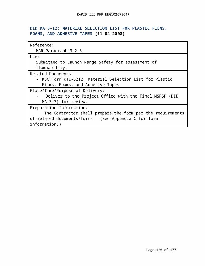
RAPID III RFP NNG10207304R
DID MA 12-5: NONDESTRUCTIVE EVALUATION PLAN (02-19-2009)
Title:Nondestructive Evaluation Plan
DID No.:MA 12-5
Reference:MAR Paragraph 12.5
Use:Establishes the Non-Destructive Evaluation (NDE) plan for the procedures and specifications employed in the inspection of materials.
Related Documents:- NASA-STD-6016, Standard Materials and Processes Requirement for Spacecraft- MIL-HDBK-6870, Inspection Program Requirements, Nondestructive for Aircraft and
Missile Materials and Parts- NASA-STD-5009, Nondestructive Evaluation Requirements for
Fracture-Critical Metallic ComponentsPlace/Time/Purpose of Delivery:- Deliver to the Project Office thirty (30) days prior to PDR for review.- Deliver updates to the Project Office thirty (30) days after identification for review.
Preparation Information:- The NDE Plan shall describe the process for establishment, implementation, execution
and control of NDE. The plan shall meet the intent of MIL-HDBK-6870s and NASA-STD-5009 as specified by NASA-STD-6016.
The plan shall define NDT planning and requirements to include the following:- Hardware Design;- Manufacturing Planning;- Personnel Training;- NDE Reliability Requirements for Fracture Critical Parts; and- NDE Reporting.
Page 120 of 126
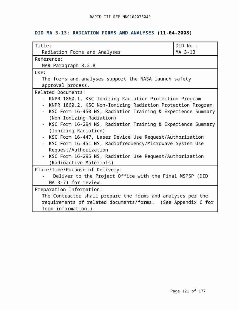
RAPID III RFP NNG10207304R
DID MA 12-6: PRINTED WIRING BOARDS (PWB) TEST COUPONS AND/OR COUPON ANALYSIS REPORTS (04-18-2008)
Title:Printed Wiring Board (PWB) Test Coupons
DID No.:MA 12-6
Reference:MAR Paragraph 12.6
Use:PWB test coupons are evaluated to validate that PWBs are suitable for use in space flight and mission critical ground applications.
Related Documents:- IPC-6011, Generic Performance Specifications for Printed Boards (Class 3
Requirements)- IPC-6012B, Qualification and Performance Specification for Rigid Printed Boards
(Class 3/A Requirements /Performance Specification Sheet for Space and Military Avionics)
- IPC-6013B, Qualification and Performance Specification for Flexible Printed Boards (Class 3 Requirements)
- IPC-6018A, Microwave End Product Board Inspection and Test - IPC A-600G, Guidelines for Acceptability of Printed Boards (Class 3 Requirements)
Place/Time/Purpose of Delivery:- Deliver test coupons and supporting manufacturing information traceable to the flight
boards to the Project Office or to a Customer/Project Office-approved laboratory as soon as practicable for analysis of the printed wiring boards for approval.
- In the case that a Project Office/Customer-approved laboratory is used, deliver the coupon analysis report/laboratory results to the Project Office within ten (10) days of receipt from the laboratory for approval.
Preparation Information:- Notify Project Office/Customer regarding shipment of PWB test coupons.- Laboratory coupon analysis report format is acceptable.
Page 121 of 126
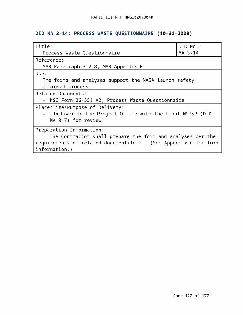
RAPID III RFP NNG10207304R
DID MA 13-1: CONTAMINATION CONTROL PLAN AND DATA (04-18-2008)
Title:Contamination Control Plan and Data
DID No.:MA 13-1
Reference:MAR Paragraph 13.1
Use:To establish contamination allowances, methods for controlling contamination, and record test results.
Related Documents:- GSFC-STD-7000, General Environmental Verification Standard (GEVS) for GSFC
Flight Programs and Projects- GSFC-STD-1000, Rules for the Design, Development, Verification, and Operation of
Flight Systems- ASTM E595-07, Standard Test Methods for Total Mass Loss and Collected Volatile
Condensable Materials from Outgassing in a Vacuum Environment- Outgassing Data for Selecting Spacecraft Materials (URL: http://outgassing.nasa.gov/)
Place/Time/Purpose of Delivery:- Deliver initial plan to the Project Office thirty (30) days before PDR for GSFC review.- Deliver final plan to the Project Office thirty (30) days before the CDR for approval.- Deliver final thermal vacuum bakeout results to the Project Office within thirty (30)
days of completion for review.- Deliver contamination certificate of compliance with the End Item Acceptance Data
Package (DID MA16-1) for review.Preparation Information:
The Contractor shall provide: material properties data; design features; test data; system tolerance of degraded performance; and methods to prevent degradation. The items below shall be addressed in the plan:- Beginning of life and end of life contamination requirements for contamination sensitive
surfaces or subsystems.- Methods and procedures used to measure and maintain the levels of cleanliness required
during each of the various phases of the item’s lifetime (e.g., protective covers, environmental constraints, purges, cleaning/monitoring procedures).
- Materials:- Outgassing as a function of temperature and time;- Nature of outgassing chemistry; and- Areas, weight, location, view factors of critical surfaces.
- Venting: size, location and relation to external surfaces.- Thermal vacuum test contamination monitoring plan, to include vacuum test data, QCM
location and temperature, pressure data, system temperature profile, and shroud temperature.
- On-orbit spacecraft and instrument performance as affected by contamination deposits.- Contamination effect monitor;- Methods to prevent and recover from contamination in orbit;- Evaluation of on-orbit degradation
Page 122 of 126

RAPID III RFP NNG10207304R
DID MA 13-1: CONTAMINATION CONTROL PLAN AND DATA (CONTINUED)
- Photopolymerization of outgassing products on critical surfaces;- Space debris risks and protection; and- Atomic oxygen erosion and re-deposition.
- Analysis of contamination impact on the satellite on orbit performance.- In orbit contamination impact from other sources such as the Space Transportation
System (STS), space station, and adjacent instruments.- Ground/Test support equipment controls to prevent contamination of flight item(s).- Facility controls and processes to maintain hardware integrity (protection and
avoidance).- Training.- Data package on test results for materials and as-built product.
Page 123 of 126
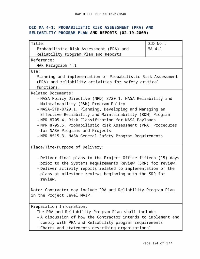
RAPID III RFP NNG10207304R
DID MA 15-1: GIDEP ALERT / NASA ADVISORY DISPOSITIONS (04-18-2008)
Title:GIDEP Alert / NASA Advisory Dispositions
DID No.:MA 15-1
Reference:MAR Paragraph 15.4
Use:Document the Contractor's disposition of GIDEP ALERTs; GIDEP SAFE-ALERTs; GIDEP Problem Advisories; GIDEP Agency Action Notices; NASA Advisories and component issues, hereinafter referred to collectively as “Alerts” with respect to parts and materials used in NASA product.
Related Documents:- S0300- BT-PRO-010, GIDEP Operations Manual - S0300-BU-GYD-010, GIDEP Requirements Guide
Place/Time/Purpose of Delivery:- Existing Alert Submittals: Deliver disposition of existing Alerts to the Project Office
within thirty (30) days of identification of potential use, or use, of an EEE part or material for review.
- New/Subsequent Alert Submittals: Deliver disposition of subsequent Alerts that shall be provided by the Project Office, regarding EEE parts or materials that have been already approved for use to the Project Office within thirty (30) days of Alert receipt for review.
Preparation Information:The Contractor shall use the Program Approved Parts List (PAPL) (DID MA 11-3), the As-Designed Parts List (ADPL) (DID MA 11-4), the As-Built Parts List (ABPL) (DID MA-5), and the Materials Identification and Usage List (MIUL) (DID MA 12-4) to prepare this deliverable. The Contractor shall submit the following:- For Existing Alert Submittals: Compare the list of existing Alerts against the Lists noted
above, inserting a notation for each line item as to whether there are applicable Alerts. - As new parts and materials are added to the PAPL, ADPL, ABPL, or MIUL; update
the affected list with GIDEP information.- For New/Subsequent Alert Submittals: Update the PAPL, ADPL, ABPL, or MIUL with
Alert information as the Contractor is notified about new Alerts by the Project Office and/or GIDEP.
- Complete a GSFC Form 4-37, “Problem Impact Statement Parts, Materials and Safety,” or equivalent Contractor form, for Alerts provided by the GSFC Project Office. (See Appendix C for form information.).
Page 124 of 126
RAPID III RFP NNG10207304R
DID MA 15-2 DOCUMENTATION ON SIGNIFICANT PARTS, MATERIALS, AND SAFETY PROBLEMS (04-18-2008)
Title:Documentation on Significant Parts, Materials, and Safety Problems
DID No.:MA 15-2
Reference:MAR Paragraph 15.4
Use:Document the Contractor's identification of significant parts, material, and safety problems and the Contractor’s actions as required by the GIDEP manual regarding the decision to prepare an Alert, including the type of Alert that is applicable.
Related Documents:- S0300- BT-PRO-010, GIDEP Operations Manual - S0300-BU-GYD-010, GIDEP Requirements Guide
Place/Time/Purpose of Delivery:- Deliver to the Project Office within thirty (30) days of identification for review.
Preparation Information:The Contractor shall submit relevant information (e.g., failure analyses, test reports, root cause and corrective action evaluations).
Page 125 of 126
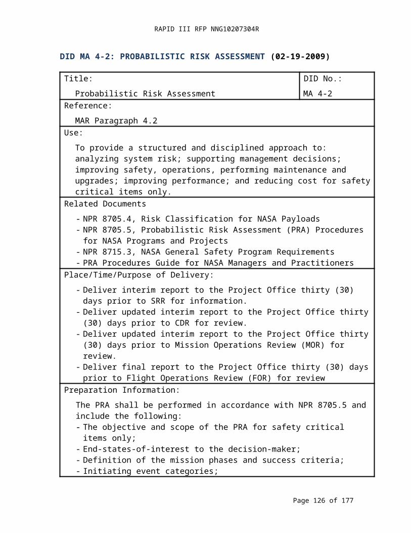
RAPID III RFP NNG10207304R
DID MA 16-1: END ITEM ACCEPTANCE DATA PACKAGE (04-18-2008)
Title:End Item Acceptance Data Package
DID No.:MA 16-1
Reference:MAR Paragraph 16.1
Use:The End Item Acceptance Data Package documents the design, fabrication, assembly, test, and integration of the hardware and software being delivered and is included with the end item delivery.
Related Documents:NonePlace/Time/Purpose of Delivery:
Deliver to the Project thirty (30) days prior to end item delivery for approval.Preparation Information:
The Contractor prepares the End Item Acceptance Data Package as part of design development and implementation such that it is completed prior to delivery. The following items shall be included:- The deliverable item name, serial number, part number, and classification status (e.g.,
flight, non-flight, ground support, etc.).- Appropriate approval signatures (e.g., Contractors quality representative, product design
lead, Government Representative, etc.).- List of shortages or open items at the time of acceptance with supporting rationale.- As-built serialization. - As-built configuration.- In-process Work Orders (available for review at Contractors--not a deliverable).- Final assembly and test Work Order.- Nonconformance reports.- Acceptance testing procedures and report(s), including environmental testing.- Trend data.- Anomaly/problem failure reports with root cause and corrective action dispositions.- As-built EEE parts list. - As-built materials list.- Chronological history, including:
- Total operating hours and failure-free hours of operation; and- Total number of mechanical cycles and remaining cycle life.
- Limited life items, including data regarding the life used and remaining.- As-built final assembly drawings.- PWB coupon results.- Photographic documentation of hardware (pre and post-conformal coating for printed
wiring assemblies, box or unit, subsystem, system, harness, structure, etc.).- Waivers.- Certificate of Compliance which were signed by management.
Page 126 of 126

![[PPT]PowerPoint Presentation - The Committee on Earth ...ceos.org/document_management/Meetings/Plenary/30... · Web viewNASA GSFC • USGS EROS Landsat 9 KDP-B APMC August 17, 2016](https://img.pdfslide.us/doc/110x75/5aa514a77f8b9a517d8cc7ae/pptpowerpoint-presentation-the-committee-on-earth-ceosorgdocumentmanagementmeetingsplenary30web.jpg)