Embed Size (px)
Citation preview
The International Journal of Human Factors in Manufacturing, Vol. 4 (3) 321-338 (1994) Q 1994 John Wiley & Sons, Inc. CCC 1045-2699/94/030321-18
Rapid Prototyping-The Swedish Industry Experience Lars Trygg Department of Industrial Management and Economics, Chalmers University of Technology, 4 12 96 Gothenburg, Sweden
ABSTRACT
The growing emphasis on timeliness as a competitive weapon has forced companies around the world to search for time-slacks and other possibilities to reduce lead times in the process of product refinement. In this respect, an especially interesting bottleneck is the development and manufacturing of prototypes. Traditional prototype methods, mostly performed by craftsmen, are known to be both costly and time-consuming. However, the development within the IT area has lately made it possible to speed up and compress this particular process step. Depending on the purpose of the prototype, a new technology called Rapid Prototyping can be used in many situations, reducing lead times in the development of prototypes from weeks and months down to hours, hence affecting the overall lead time. However, adopting this new technology also means considerably new working requirements as well as new options for most actors involved in the product development process, including external participants. Especially cross-functional and cross-organizational collaboration is strongly promoted by this technology, improving working relationships. 0 1994 John Wiley & Sons, Inc.
1. INTRODUCTION
“Time-based competition,” that is, the ability to quickly develop, produce, and distrib- ute new products and processes, has become increasingly important as a strategic means of competition. Increasing emphasis on the time factor is due primarily to an accelerated technological development, to growing international competition, as well as to progres- sive development and diversification of customer needs (Blackburn, 1991 ; Musselwhite, 1990). The emphasis on accelerating the product development process is not new, but it is not until recently that the manifold benefits of being a fast innovator have been highlighted and used as a change agent. The rewards have shown to be plentiful for companies that are able to quickly bring about products at the time they are demanded by the market (Salk, 1988). For instance, a model developed by McKinsey & Co. showed that a product 6 months late to market, but on budget, misses out on one-third of the potential profit over the product’s lifetime. In contrast, a product coming out on time and 50% over budget cuts profits by only 4% (Dumaine, 1989). Some other benefits of being a fast innovator can be summarized by the following: “Not only can they charge a premium price for their exclusive products but they can also incorporate more up-to-date technology in their goods and respond faster to emerging market niches and changes in taste” (Wall Street Journal, 1988, p. 1).
321
322 TRYGG
As the importance of the time factor has increased, the traditional, sequential, product development process has correspondingly been criticized for being ill-suited to respond to the “new” demands. A product development process in accordance with a “relay race” is usually fairly time-consuming, and it does not usually bring out optimal market-oriented products or products adapted to manufacturing (Blackburn, 199 1 ; Trygg, 1992). The product designs developed during “over-the-fence” engineering are therefore usually inefficient to manufacture and they often need to be reworked once those responsible for quality, manufacturing, maintenance, and purchasing, etc. have a look at them. The continuing struggle for lead time reductions and the need for better market-oriented products have consequently led to an intensified search for alternative organizational solutions and for different work methods and tools to be used.
The new forms and principles of product development highlighted lately, often under an overall heading such as Concurrent Engineering, are basically not new and revolu- tionary, even though the use of some methods has accelerated during these years. Hence, a number of companies have for a long time, and with great success, been working in accordance with many of the highlighted principles (Hartley and Mortime, 1990; Rosenblatt and Watson, 1991). What is new is the strong focus on the concurrent use of many of the principles and also on how the time factor is used as an organizational rationalization instrument or “change agent.” The primary gain with these new product development concepts lies in that they have brought forward a large number of key elements, which together have been shown to be critical in the struggle to develop customer-oriented products in a short time. What these organizational solutions, work methods, and tools also have in common is that they all focus upon all the information needed being available as early as possible in the development process, to reduce slack time and unnecessary rework, and to facilitate the earliest possible start of the different development subtasks (i.e., to do the job right the first time).
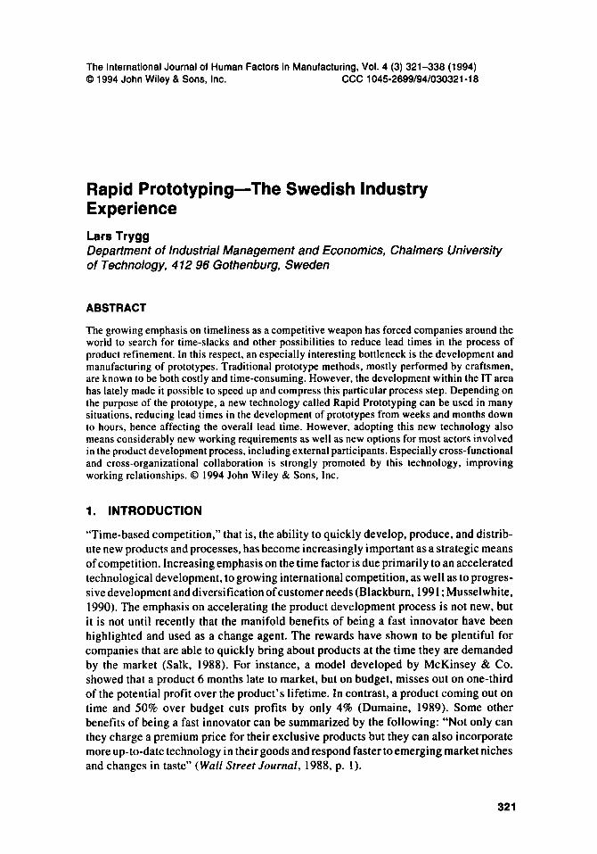
Today it is quite clear that the key ingredient in Concurrent Engineering is teamwork, and also that “Multifunctional teams are currently the most effective way known to cut through barriers to good design” (Whitney, 1988) (Fig. I). In these teams, representa- tives of as many functions as possible collaborate during the total development project’s life cycle, to ensure that it reflects customers’ needs and desires, as well as the restrictions and possibilities of the manufacturing process. In the best-case scenario, representatives from, for example, engineering, manufacturing, marketing, and pur- chasing, as well as suppliers and customers, work together from the outset to anticipate problems and bottlenecks and to eliminate them at an early stage, to avoid delays in bringing the product to market and costly failures in service (Trygg, 1992).
Figure 1 The key attributes of Concurrent Engineering.
RAPID PROTOTYPING 323
Within the area of Concurrent Engineering, also a large number of product develop- ment-related tools and methods exist, to increase the product and process efficiency and effectiveness (Trygg. 1992; Winner, et al., 1988). However, these methods are quite difficult to categorize because they are developed to serve a large variety of purposes, and also because they are used at different stages of the development process [Design For Manufacturability and Assembly (DFMA), Quality Function Deployment (QFD), Failure Mode and Effect Analysis (FMEA), Robust Design (Taguchi methods), Fault Tree Analysis (FTA), Variation Simulation Analysis (VSA), Pareto charts, Design experiments, Quality Loss Function (QLF), etc.]. Experience shows that the proper use of these methods can have a strong impact on development efficiency, especially with regard to lead time, producibility, and to market acceptance.
In addition, to maximize the benefits of Concurrent Engineering, the two, tradition- ally separated, computer environments, CAD and CAM, need to be effectively inte- grated (Hartley and Mortime, 1990). With the right combination of systems (i.e., hardware and software), design and production engineers can work in parallel, with tools and fixtures being developed at the same time as the products. Through a well- developed CAD/CAM integration, time-consuming programming of NC machines is removed because, although design changes to a component are being made by the CAD system, the system concurrently generates the NC codes. However, many of today’s designers are hesitating to use the most advanced CAD techniques, primarily due to their subjectively anticipated complexity (i.e., 3-D Surface and Solid models), and also, far from all designs need to be developed by such advanced techniques. Therefore, very few companies can today be claimed to have a fully integrated CAD/CAM environment.
Furthermore, by combining computer-aided tools and computer-based support of product design, production planning, and production with other engineering support systems [e.g., solid modeling, finite element modeling (FEM), engineering analysis, system dynamics, computer-aided testing (CAT), and design guidance rules (e.g., DFMA)] into a common data base accessible to design as well as to manufacturing, great possibilities are opened up for the efficient design and smooth transfer of technology to production (Winner et al., 1988). The number of prototypes required is hereby reduced, because the designers can make computerized simulations and analy- ses on solid models regarding a product’s geometry, dimensions, loads, and material properties. It is also possible to test and analyze the ability to produce and assemble the product, because the solid models include a complete mathematical representation of the product, which in turn leads to fewer iterations (i.e., design changes) between design and production (Brazier and Leonard, 1990). Companies that use 3-D Surface or Solid models, as they develop new products, can also benefit from a relatively new technol- ogy breakthrough within the area of prototype production. This new technology, or actually a set of related methods collectively known as Rapid Prototyping techniques, developed during the past 5 years, can slash prototype production lead times by as much as one-tenth. The technology is also, by its nature, supporting cross-functional integra- tion. Critical information is hereby transferred “upstream” in the development process, reducing time consuming changes later on.
2. AIM AND PURPOSE
The aim of this paper is to discuss the developments within the area of Rapid Prototyping, and to highlight some of the experiences drawn by one of Europe’s earliest
324 TRYGG
(i.e.. the second) adopters of this technology. Also, new and critical working require- ments as well as options emerging due to the use of this technology will be outlined. Furthermore, the Information Technology (IT) requirements needed, necessary to gain the benefits of the Rapid Prototyping technology, will be view along with a presentation of the current status of the Swedish manufacturing industry with respect to these requirements.
3. RAPID PROTOTYPING
3.1. The Need for Rapid Prototypes-the Need for Speed
As the ability to quickly develop, produce, and distribute new products and processes has become increasingly important as a strategic means of competition, the need for a rapid prototyping and model-building capability has increased correspondingly. When companies move toward a flexible manufacturing setting, with a variety of product models as they customize their products, and as they attempt to improve customer service and respond more quickly to market changes, they cannot afford to wait for prototypes that take months to be manufactured. Hence, prototypes are needed faster and faster, and they need to be more accurate and more representative of the final object. This is where Rapid Prototyping comes in (Plunkett, 1992).
Most engineers use models and prototypes to test and verify their design solutions. The traditional methods used to manufacture prototypes have often been labor inten- sive, involving extensive tooling and complicated machining operations. Historically, prototypes commonly required lead times of several weeks to several months to be produced, depending on complexity and material used. The introduction of CAD and computer-numerically controlled (CNC) machines in the 1970s resulted in substantial labor savings in the fabrication of prototypes. The use of these techniques especially reduced the amount of time required, down to days and weeks instead of months. However, recent advances in the area of Rapid Prototyping have reduced the cycle time even further, from weeks down to hours and days. These new techniques enable designers and engineers, with a minimum of human interaction and directly from the CAD data, to have a model or prototype of a designed product on the very day it is designed (Blake, 1992).
Traditionally, while the designers wait for their prototypes to be manufactured, shipped, and handled, which can take weeks and months, they fill their agenda with other tasks, not necessarily related to the previous one. Then, when the prototype arrives, the designers are often heavily devoted to their new assignments, putting the prototype on hold until they are finished. At that time, when the designers return to the prototype to continue their work, they often need to spend unproductive time to get back on the track. Today, with such short lead times, the designers can stay focused to a much higher extent on the same project from start until they are finished.
3.2. An Overview of Rapid Prototyping Techniques and Systems Requirements
The fundamental application of prototyping has been, and still is, to produce prototype models for design engineers. The difference between the new Rapid Prototyping (RP) techniques, discussed in this paper, and the traditional prototyping manufacturing
RAPID PROTOTYPING 325
methods is that most of these new techniques are based on a process that successively adds material to the object under fabrication. Traditional methods are either based on a process that deforms the right amount of bulk material into a required shape (e.g.. forging, stamping, drawing, extruding) or on a process that removes excess material from a bulk of material that is larger than the required shape (e.g., turning, milling, grinding, etc.) (Kruth, 1991).
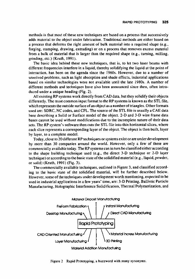
The basic idea behind these new techniques, that is, to let two laser beams with different frequencies interfere in a liquid, thereby solidifying the liquid at the point of interaction, has been on the agenda since the 1960s. However, due to a number of unsolved problems, such as light absorption and shade effects, industrial applications based on similar technologies were not available until the late 1980s. A number of different methods and techniques have also been announced since then, often intro- duced under a unique heading (Fig. 2).
All existing RP systems work directly from CAD data, but they solidify their objects differently. The most common input format to the RP systems is known as the STL file, which represents the outside surface of an object as a number of triangles. Other formats used are: SDRC, NC codes, and CFL. The source of the STL file is usually a CAE data base describing a Solid or Surface model of the object. 2-D and 3-D wire frame data bases cannot be used without modifications due to the incomplete nature of their data sets. The RP system's software then cuts the STL file into thin horizontal slices, where each slice represents a corresponding layer of the object. The object is then built, layer by layer, to a complete model.
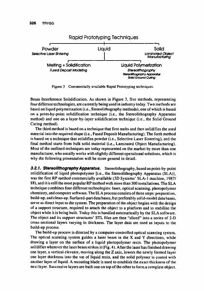
Today, close to 20 different RP techniques or systems exist or are underdevelopment by more than 30 companies around the world. However, only a few of these are commercially available today. The RP systems can in turn be classified either according to the shape building technique used (e.g., the direct 3-D technique or 2-D layer technique) or according to the basic state of the solidified material (e.g., liquid, powder, or solid) (Kruth, 1991) (Fig. 3).
The commercially available techniques, outlined in Figure 3, and classified accord- ing to the basic state of the solidified material, will be further described below. However, some of the techniques under development worth mentioning, expected to be used in industrial applications in a few years' time, are: 3-D Printing, Ballistic Particle Manufacturing, Holographic Interference Solidification, Thermal Polymerization, and
Mafemi Deposd Manutactumg w
FreForm fabrication Instant Manufacturing
Desktop Manufactun'ng Direct CAD Manufacturing
Rapid Protolyping
CAD Oriented Manufacturing Material Incress Manufacturing
Layer Manufacturing
Material Addition Manufacturing
Figure 2 Rapid Prototyping, a buzzword with many synonyms.
326 TRYGG
Rapid Prototyping Techniques I
Powder Selectfve Laser Snterlng
I
Liquid I
Solid Lamhated Oblect
Manufactwhg I
Melting + Solidification Fused Deparft Modeiiw
Figure 3 Commercially available Rapid Prototyping techniques.
Beam Interference Solidification. As shown in Figure 3, five methods, representing four different technologies, are currently being used in industry today. Two methods are based on liquid polymerization (i.e., Stereolithography methods), one of which is based on a point-by-point solidification technique (i.e., the Stereolithography Apparatus method) and one on a layer-by-layer solidification technique (i.e., the Solid Ground Curing method).
The third method is based on a technique that first melts and then solidifies the used material into the required shape (i.e.. Fused Deposit Manufacturing). The forth method is based on a technique that solidifies powder (i.e., Selective Laser Sintering), and the final method starts from bulk solid material (i.e., Laminated Object Manufacturing). Most of the outlined techniques are today represented on the market by more than one manufacturer, who usually works with slightly different operational solutions, which is why the following presentation will be more general in detail.
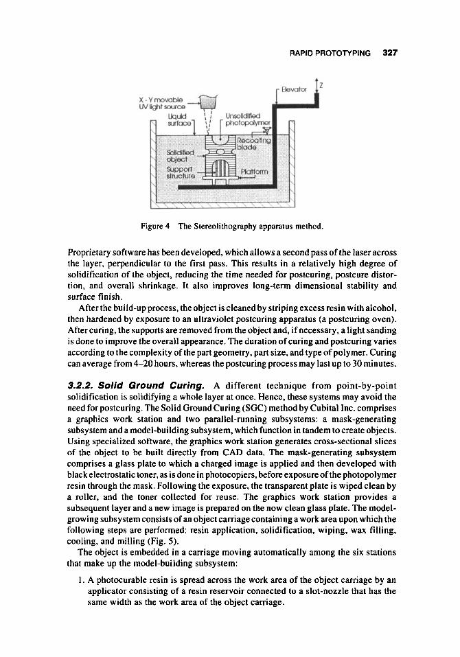
3.2.1. Stefeo/~t~ogf8~~yApparatus. Stereolithography, based on point-by-point solidification of liquid photopolymer [i.e., the Stereolithography Apparatus (SLA)], was the first RP method commercially available (3D Systems’ SLA-1 machine, 1987/ 88), and it is still the most popular RP method with more than 300 installations. The SLA technique combines four different technologies: laser, optical scanning, photopolymer chemistry, and computer software. The SLA process consists of three steps: preparation, build-up, and clean-up. Surfaced-part data bases, but preferably solid-model data bases, serve as direct input to the system. The preparation of the object begins with the design of a support structure, required to attach the object to a platform and to stabilize the object while it is being built. Today this is handled automatically by the SLA software. The object and its support structures’ STL files are then “sliced” into a series of 2-D cross-sectional layers varying in thickness. The layer data are used as inputs to the build-up process.
The build-up process is directed by a computer-controlled optical scanning system. The optical scanning system guides a laser beam in the X and Y directions, while drawing a layer on the surface of a liquid photopolymer resin. The photopolymer solidifies wherever the laser beam strikes it (Fig. 4). After the laser has finished drawing one layer, a vertical elevator, moving along the Z axis, lowers the newly formed layer one layer thickness into the vat of liquid resin, and the solid polymer is coated with another layer of liquid. A recoating blade is used to establish the exact thickness of the next layer. Successive layers are built one on top of the other to form a complete object.
RAPID PROTOTYPING 327
x-vmavoble wllgtoavce
Figure 4 The Stereolithography apparatus method.
Proprietary software has been developed, which allows a second pass of the laser across the layer, perpendicular to the first pass. This results in a relatively high degree of solidification of the object, reducing the time needed for postcuring, postcure distor- tion, and overall shrinkage. It also improves long-term dimensional stability and surface finish.
After the build-up process, the object is cleaned by striping excess resin with alcohol, then hardened by exposure to an ultraviolet postcuring apparatus (a postcuring oven). After curing, the supports are removed from the object and, if necessary, a light sanding is done to improve the overall appearance. The duration of curing and postcuring varies according to the complexity of the part geometry, part size, and type of polymer. Curing can average from 4-20 hours, whereas the postcuring process may last up to 30 minutes.
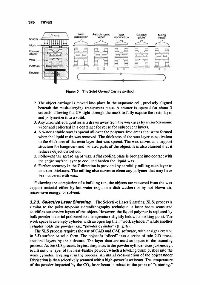
3.2.2. Solid Ground Curing. A different technique from point-by-point solidification is solidifying a whole layer at once. Hence, these systems may avoid the need for postcuring. The Solid Ground Curing (SGC) method by Cubital Inc. comprises a graphics work station and two parallel-running subsystems: a mask-generating subsystem and a model-building subsystem, which function in tandem to create objects. Using specialized software, the graphics work station generates cross-sectional slices of the object to be built directly from CAD data. The mask-generating subsystem comprises a glass plate to which a charged image is applied and then developed with black electrostatic toner, as is done in photocopiers, before exposure of the photopolymer resin through the mask. Following the exposure, the transparent plate is wiped clean by a roller, and the toner collected for reuse. The graphics work station provides a subsequent layer and a new image is prepared on the now clean glass plate. The model- growing subsystem consists of an object carriage containing a work area upon which the following steps are performed: resin application, solidification, wiping, wax filling, cooling, and milling (Fig. 5 ) .
The object is embedded in a carriage moving automatically among the six stations that make up the model-building subsystem:
I . A photocurable resin is spread across the work area of the object carriage by an applicator consisting of a resin reservoir connected to a slot-nozzle that has the same width as the work area of the object carriage.
328 TRYGG
YE3 Redn Aerodwamlc Wax Codlng cppllcotion wiper opp~cotlon pkrte
Figure 5 The Solid Ground Curing method.
2. The object carriage is moved into place in the exposure cell, precisely aligned beneath the mask-carrying transparent plate. A shutter is opened for about 3 seconds, allowing the UV light through the mask to fully expose the resin layer and polymerize it to a solid.
3. Any unsolidified liquid resin is drawn away from the work area by an aerodynamic wiper and collected in a container for reuse for subsequent layers.
4. A water-soluble wax is spread all over the polymer-free areas that were formed when the liquid resin was removed. The thickness of the wax layer is equivalent to the thickness of the resin layer that was spread. The wax serves as a support structure for hangovers and isolated parts of the object. It is also claimed that it reduces object distortion.
5 . Following the spreading of wax, a flat cooling plate is brought into contact with the entire surface layer to cool and harden the liquid wax.
6. Further accuracy in the Z direction is provided by carefully milling each layer to an exact thickness. The milling also serves to clean any polymer that may have been covered with wax.
Following the completion of a building run, the objects are removed from the wax support material either by hot water (e.g., in a dish washer) or by hot blown air, microwave energy, or solvent.
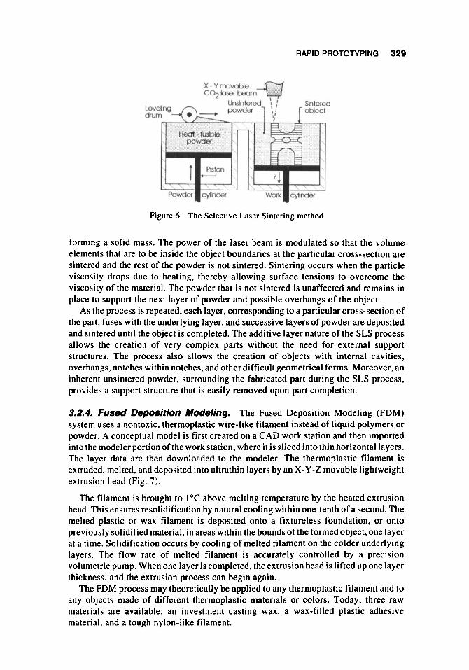
3.2.3. Selective Laser Slntering. The Selective Laser Sintering (SLS) process is similar to the point-by-point stereolithography technique; a laser beam scans and solidifies successive layers of the object. However, the liquid polymer is replaced by bulk powder material preheated to a temperature slightly below its melting point. The work space is an empty cylinder with an open top (i.e., “work cylinder,” while another cylinder holds the powder (i.e., “powder cylinder”) (Fig. 6).
The SLS process requires the use of CAD and CAE software, with designs created in 3-D surface or solid form. The object is “sliced“ into a series of thin 2-D cross- sectional layers by the software. The layer data are used as inputs to the scanning process. As the SLS process begins, the piston in the powder cylinder rises just enough to lift out one layer of the heat-fusible powder, which a leveling drum pushes into the work cylinder, leveling it in the process. An initial cross-section of the object under fabrication is then selectively scanned with a high-power laser beam. The temperature of the powder impacted by the CO, laser beam is raised to the point of “sintering,”
RAPID PROTOTYPING 329
Figure 6 The Selective Laser Sintering method
forming a solid mass. The power of the laser beam is modulated so that the volume elements that are to be inside the object boundaries at the particular cross-section are sintered and the rest of the powder is not sintered. Sintering occurs when the particle viscosity drops due to heating, thereby allowing surface tensions to overcome the viscosity of the material. The powder that is not sintered is unaffected and remains in place to support the next layer of powder and possible overhangs of the object.
As the process is repeated, each layer, corresponding to a particular cross-section of the part, fuses with the underlying layer, and successive layers of powder are deposited and sintered until the object is completed. The additive layer nature of the SLS process allows the creation of very complex parts without the need for external support structures. The process also allows the creation of objects with internal cavities, overhangs, notches within notches, and other difficult geometrical forms. Moreover, an inherent unsintered powder, surrounding the fabricated part during the SLS process, provides a support structure that is easily removed upon part completion.
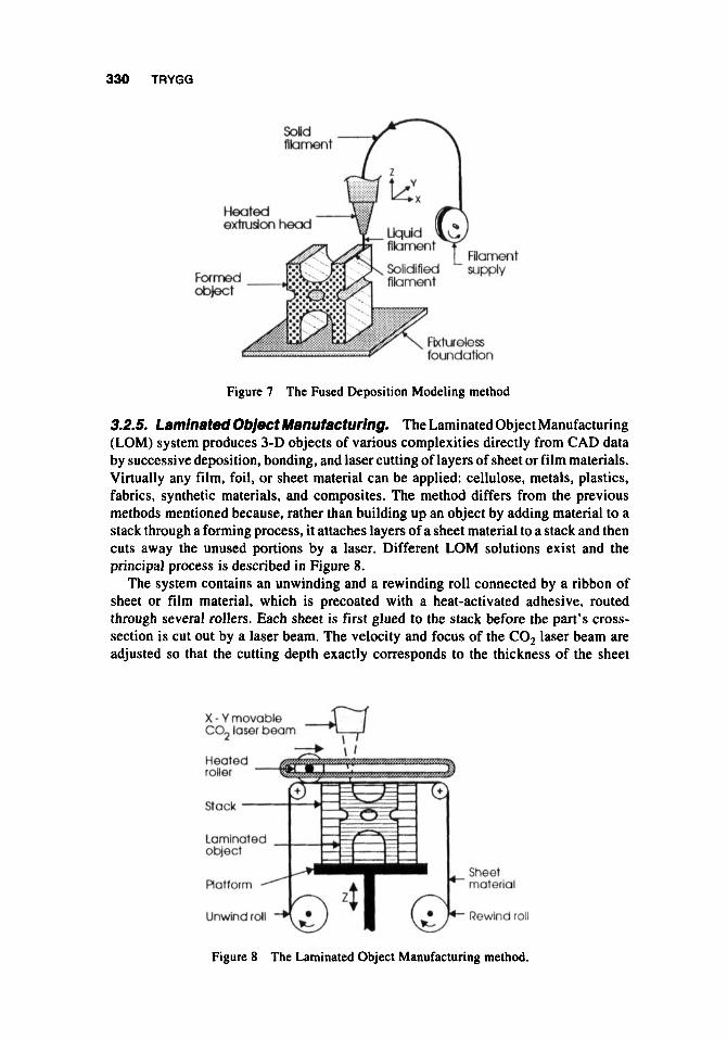
3.2.4. Fused Deposition Modeling. The Fused Deposition Modeling (FDM) system uses a nontoxic, thermoplastic wire-like filament instead of liquid polymers or powder. A conceptual model is first created on a CAD work station and then imported into the modeler portion of the work station, where i t is sliced into thin horizontal layers. The layer data are then downloaded to the modeler. The thermoplastic filament is extruded, melted, and deposited into ultrathin layers by an X-Y-Z movable lightweight extrusion head (Fig. 7).
The filament is brought to 1°C above melting temperature by the heated extrusion head. This ensures resolidification by natural cooling within one-tenth of a second. The melted plastic or wax filament is deposited onto a fixtureless foundation, or onto previously solidified material, in areas within the bounds of the formed object, one layer at a time. Solidification occurs by cooling of melted filament on the colder underlying layers. The flow rate of melted filament is accurately controlled by a precision volumetric pump. When one layer is completed, the extrusion head is lifted up one layer thickness, and the extrusion process can begin again.
The FDM process may theoretically be applied to any thermoplastic filament and to any objects made of different thermoplastic materials or colors. Today, three raw materials are available: an investment casting wax, a wax-filled plastic adhesive material, and a tough nylon-like filament.
330 TRYGG
Fun ob$
Figure 7 The Fused Deposition Modeling method
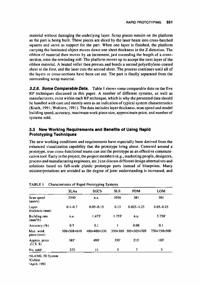
3.2.5. Laminated Object ~anufactufing. The Laminated Object Manufacturing (LOM) system produces 3-D objects of various complexities directly from CAD data by successive deposition, bonding, and laser cutting of layers of sheet or film materials. Virtually any film, foil, or sheet material can be applied: cellulose, metals, plastics, fabrics, synthetic materials, and composites. The method differs from the previous methods mentioned because, rather than building up an object by adding material to a stack through a forming process, it attaches layers of a sheet material to a stack and then cuts away the unused portions by a laser. Different LOM solutions exist and the principal process is described in Figure 8.
The system contains an unwinding and a rewinding roll connected by a ribbon of sheet or film material, which is precoated with a heat-activated adhesive, routed through several rollers. Each sheet is first glued to the stack before the part’s cross- section is cut out by a laser beam. The velocity and focus of the CO, laser beam are adjusted so that the cutting depth exactly corresponds to the thickness of the sheet
C02 X-Ymovable laser beam 4
Sheet material
Rewind roll
Figure 8 The Laminated Object Manufacturing method.
RAPID PROTOTYPING 331
material without damaging the underlying layer. Scrap pieces remain on the platform as the part is being built. These pieces are diced by the laser beam into cross-hatched squares and serve as support for the part. When one layer is finished, the platform carrying the laminated object moves down one sheet thickness in the Z direction. The ribbon of material then moves by an increment, just exceeding the length of a cross- section, onto the rewinding roll. The platform moves up to accept the next layer of the ribbon material. A heated roller then presses and bonds a second polyethylene-coated sheet to the first, and the laser cuts the second sheet. The process continues until all of the layers or cross-sections have been cut out. The part is finally separated from the surrounding scrap material.
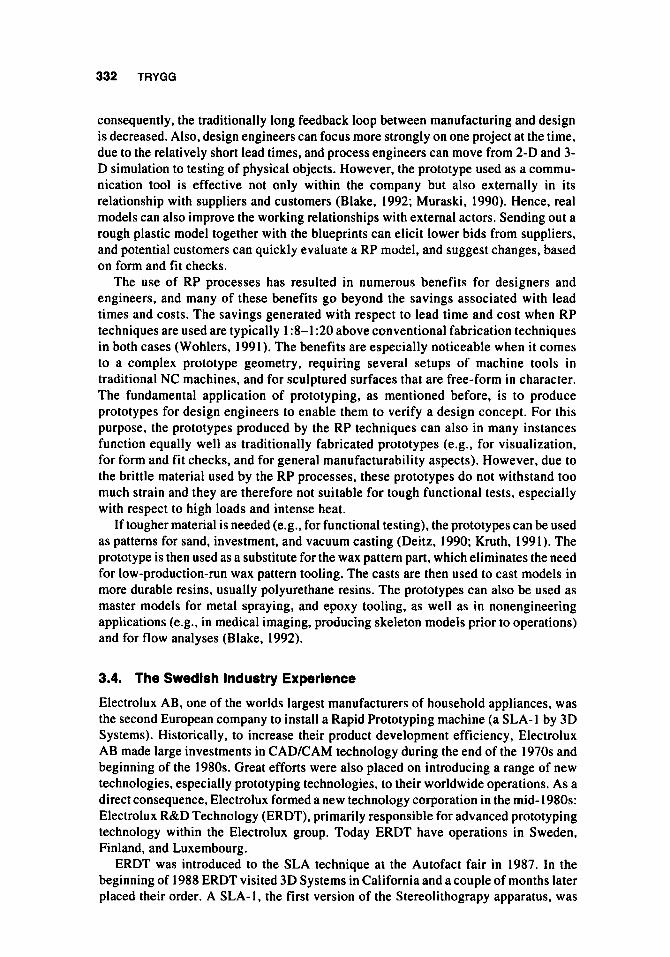
3.2.6. Some Comparable Data. Table 1 shows some comparable data on the five RP techniques discussed in this paper. A number of different systems, as well as manufacturers, exist within each RP technique, which is why the presented data should be handled with care and merely seen as an indication of typical system characteristics (Kruth, 1991; Wohlers, 199 1). The data includes layer thickness, scan speed and model building speed, accuracy, maximum work piece size, approximate price, and number of systems sold.
3.3 New Working Requirements and Benefits of Using Rapid Prototyping Techniques
The new working conditions and requirements have especially been derived from the enhanced visualization capability that the prototype bring about. Centered around a prototype, true cross-functional teams can use the prototype as an effective communi- cation tool. Early in the project, the project members (e.g., marketing people, designers, process and manufacturing engineers, etc.) can discuss different design alternatives and solutions based on full-scale plastic prototype parts instead of blueprints. Many misinterpretations are avoided as the degree of joint understanding is increased, and
TABLE 1. Characteristics of Rapid Prototyping Systems
SLAa SGCb SLS FDM LOM
Scan speed 2540 n.a. 1016 38 1 38 I (mmls)
thickness (mm)
(mmVh)
Layer 0.1-0.7 0.05-0. I5 0. I 3 0.025-1.25 0.05-0.25
Building rate n.a. I .475' I .759' n.a. 3.750
Accuracy (a) 0.5 0.1 I 0.08 0.1
Max. work 508x508~610 480x480~330 350x380 305x305~305 750x750~500 piece (mm) Approx. price 385' 490 350 215' I00 (US. $)
No. soldC 375 1 1 5 7 3
?SLA500.3D System Tubital CApril, 1992
332 TRYGG
consequently, the traditionally long feedback loop between manufacturing and design is decreased. Also, design engineers can focus more strongly on one project at the time, due to the relatively short lead times, and process engineers can move from 2-D and 3- D simulation to testing of physical objects. However, the prototype used as a commu- nication tool is effective not only within the company but also externally in its relationship with suppliers and customers (Blake, 1992; Muraski, 1990). Hence, real models can also improve the working relationships with external actors. Sending out a rough plastic model together with the blueprints can elicit lower bids from suppliers, and potential customers can quickly evaluate a RP model, and suggest changes, based on form and fit checks.
The use of RP processes has resulted in numerous benefits for designers and engineers, and many of these benefits go beyond the savings associated with lead times and costs. The savings generated with respect to lead time and cost when RP techniques are used are typically 1 :8-1:20 above conventional fabrication techniques in both cases (Wohlers, 1991). The benefits are especially noticeable when it comes to a complex prototype geometry, requiring several setups of machine tools in traditional NC machines, and for sculptured surfaces that are free-form in character. The fundamental application of prototyping, as mentioned before, is to produce prototypes for design engineers to enable them to verify a design concept. For this purpose, the prototypes produced by the RP techniques can also in many instances function equally well as traditionally fabricated prototypes (e.g., for visualization, for form and fit checks, and for general manufacturability aspects). However, due to the brittle material used by the RP processes, these prototypes do not withstand too much strain and they are therefore not suitable for tough functional tests, especially with respect to high loads and intense heat.
If tougher material is needed (e.g., for functional testing), the prototypes can be used as patterns for sand, investment, and vacuum casting (Deitz, 1990; Kruth, 1991). The prototype is then used as a substitute for the wax pattern part, which eliminates the need for low-production-run wax pattern tooling. The casts are then used to cast models in more durable resins, usually polyurethane resins. The prototypes can also be used as master models for metal spraying, and epoxy tooling, as well as in nonengineering applications (e.g., in medical imaging, producing skeleton models prior to operations) and for flow analyses (Blake, 1992).
3.4. The Swedish Industry Experience
Electrolux AB, one of the worlds largest manufacturers of household appliances, was the second European company to install a Rapid Prototyping machine (a SLA-I by 3D Systems). Historically, to increase their product development efficiency, Electrolux AB made large investments in CAD/CAM technology during the end of the 1970s and beginning of the 1980s. Great efforts were also placed on introducing a range of new technologies, especially prototyping technologies, to their worldwide operations. As a direct consequence, Electrolux formed a new technology corporation in the mid- 1980s: Electrolux R&D Technology (ERDT), primarily responsible for advanced prototyping technology within the Electrolux group. Today ERDT have operations in Sweden, Finland, and Luxembourg.
ERDT was introduced to the SLA technique at the Autofact fair in 1987. In the beginning of 1988 ERDT visited 3D Systems in California and a couple of months later placed their order. A SLA-1, the first version of the Stereolithograpy apparatus, was
RAPID PROTOTYPING 333
installed at ERDT’s lab operations in Stockholm, in November 1988. The installation took 2 days and the fabrication of prototypes could start right away. However, the technology showed initially to carry many typical technology infant problems; for example, the technology could not live up to promised, and to some extent expected, standards. The problems were mainly related to accuracy, and material properties. ERDT also experienced the SLA-I to be slow and not especially user friendly. Especially the preparation of data, to run the machine, took longer than specified. The built-in laser-width compensation did not work, and the laser was also replaced after 6 months (after 1000 hours). Also, the STL-interface available to the CAD system used by ERDT (i.e., CATIA) could only handle Solids models, which proved to be a time- consuming bottleneck. Hence, to work with Solid modeling in 1988 was a slow and difficult processs compared to the situation today. The formed objects did also shrink a lot, causing distortion. Especially large flat surfaces were heavily affected by distortion, causing the objects to snap away from the platform.
The lack of European competence and a European-based support organization was another factor that caused some problems during the first years. All communication regarding systems characteristics and handling issues was held directly with the manufacturer located in a time zone 9 hours away. However, as more and more systems were sold to European users during 1989 and 1990, a European support organization was established.
The SLA- 1 was upgraded into a SLA-250 in 1990. At the same time 3D Systems also introduced a new material and a new technique to build the prototypes. Some of the problems regarding process speed and material properties were thereby reduced. However, the most important systems development occurred in 1991, when a totally new build-up method was introduced. It was called “starweave,” which means that objects are weaved together instead of being build by “tri-hatch” as before. By using the starweave technique the objects cure more fully, with decreasing distortion problems as a result.
In 1991, additional materials were introduced, which nowadays make designs with snap-in functions possible. A new laser generation was introduced, which also was installed at ERDT, replacing laser two after I year (after 2000 hours). The current laser, number three, is still, after more than 4000 hours, working without any problems. A new STL format, that not only handles Solids but also Surfaced model data, has also been developed. The development of the software, Bridgeworks, has made the first years’ time-consuming design of support structures to a totally automatic and rapid process. The Bridgework software saves hours and sometimes days compared to when all support structures needed to be developed manually. In 1991 3D Systems also intro- duced a new systems computer software that strongly influenced the build-up speed of the SLA process.
All system enhancements in 1991, outlined above, together with the developments within the CAD/CAM software area, made ERDT realize that the technology finally had reached its first level of maturity. As a consequence, ERDT decided to move the SLA machine from the laboratory in Stockholm to one of the production sites in Husqvarna. At the Husqvarna site, Electrolux makes, among other things, chainsaws and regular sawing machines. The need for prototypes in these operations were expected to be approximately one new prototype part per week.
The machine was then moved in June 1992 and it was at the same time once again upgraded with respect to software and material. Later on in 1992, the SLA was fully upgraded into a SLA-500. Today ERDT serves internal as well as external customers,
334 TRYGG
that is, 25% are internal Electrolux customers, of which most come from the plants in Husqvarna. The remaining 75% of the capacity is sold out to other manufacturing companies within the Swedish industry. Today the lead time to make, for example, a crankcase to a chainsaw is approximately 2 days. Day 1 is used to generate the STL file. The “slice” process is performed during the night and the part is built during day 2. ERDT experiences that very few parts take longer than 1 day to build. The capacity is therefore approximately one object, or one set of objects, per day, with the machine running every day including weekends. Over the past 2 years ERDT has made 300-400 different prototype parts per year, that is, more then one a day. During the first 2 years only some 100 prototypes were manufactured per year, mainly due to the problems discussed above.
To increase the application areas of the developed parts, ERDT uses the vacuum casting technique with silicon molds, with good results. The technology used was developed at the ERDT’s Finish site and it brings PUR objects with many different material characteristics. Even though Electrolux has had the use of a RP technique since 1988, it was at theendof 1992 that the first real benefitsof using the technology became evident to a larger population within the organization. ERDT representatives believe that one reason is that the technology did not meet the required standards until then. Another important reason is that it is proven to be difficult to convince an organization, especially design engineers, to try and to regularly use new nontraditional work methods such as an RP technique. In addition, engineers with a history in working with Solid modeling are much more likely to be early adopters than engineers with a 2-D or a 3-D wire frame background. However, by continuously offering the technique to all design and manufacturing engineers, more and more engineers will try the system and experience its benefits. The success stories will then spread around within the organi- zation, influencing others to also give it a try.
3.5. The IT Status of the Swedish Manufacturing Industry
As discussed earlier, a key requirement in order to use the RP techniques, and to fully benefit from them, is that designs are developed using either 3-D Solid or 3-D Surfaced models. Today, the industry in general is far from fully utilizing these systems. The reason for this is that both these IT techniques, 3-D Solid and Surfaced models, are relatively new to the engineering community, but also that far from all designs need such a complex and often time-consuming design method. Hence, many basic designs, especially those that are easily interpreted by design and manufacturing engineers, are being developed that are much more time and cost effective using 2-D Wire frame or Surfaced models or 3-D Wire frame data. The same requirements also apply to the possibility of effectively integrating CAD and CAM data bases, that is, to effectively transfer data geometrically between the two engineering data bases.
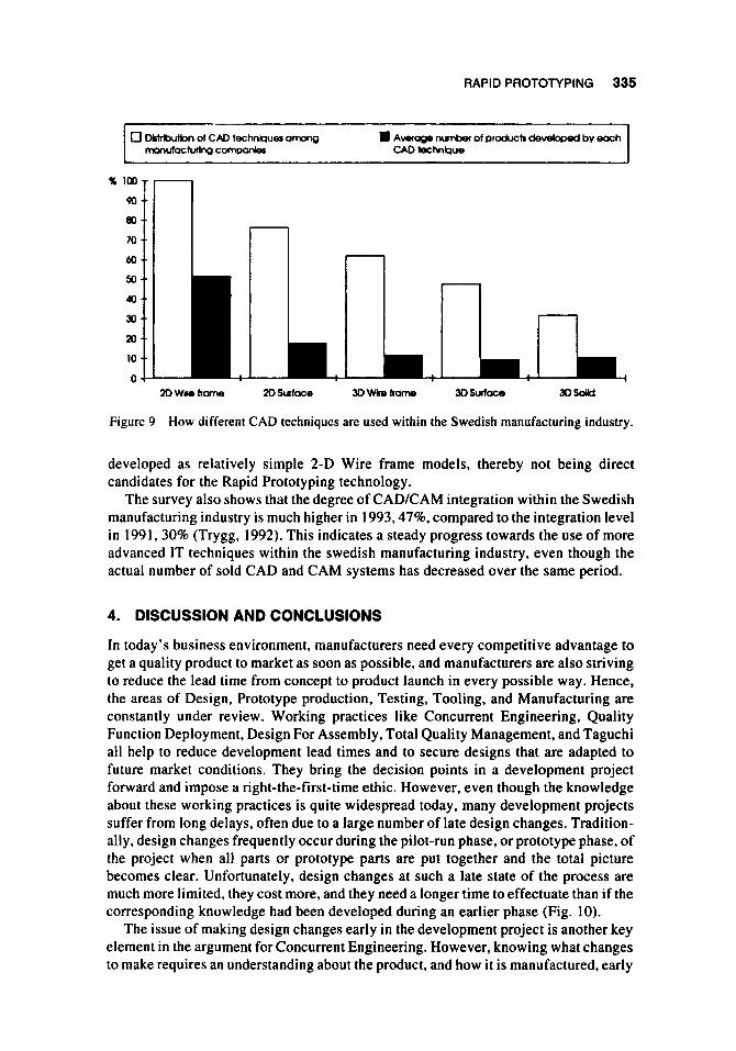
A 1993 survey of 100 of the 280 largest manufacturing business units within the Swedish manufacturing industry (77% response rate) revels that 47% of these business units use at least 3-D Surfaced modeling as they develop their products (Fig. 9); 32% of these companies use Solid modeling. However, within these companies far from all products are developed by the use of these two IT techniques. Hence, only 9% of all products, as an average, are developed with 3-D Surfaced models and 10% are developed under the guidance of a 3-D Solid modeling system (Fig. 9). As much as 52% of all products developed by the investigated business units are consequently being
RAPID PROTOTYPING 335
2D Wire hame 2D Suface
1
Figure 9 How different CAD techniques are used within the Swedish manufacturing industry.
developed as relatively simple 2-D Wire frame models, thereby not being direct candidates for the Rapid Prototyping technology.
The survey also shows that the degree of CAD/CAM integration within the Swedish manufacturing industry is much higher in 1993,47%, compared to the integration level in 1991.30% (Trygg, 1992). This indicates a steady progress towards the use of more advanced IT techniques within the Swedish manufacturing industry, even though the actual number of sold CAD and CAM systems has decreased over the same period.
4. DISCUSSION AND CONCLUSIONS
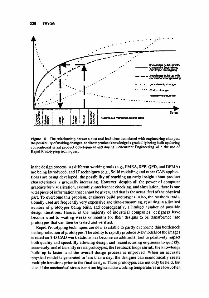
In today’s business environment, manufacturers need every competitive advantage to get a quality product to market as soon as possible, and manufacturers are also striving to reduce the lead time from concept to product launch in every possible way. Hence, the areas of Design, Prototype production, Testing, Tooling, and Manufacturing are constantly under review. Working practices like Concurrent Engineering, Quality Function Deployment, Design For Assembly, Total Quality Management, and Taguchi all help to reduce development lead times and to secure designs that are adapted to future market conditions. They bring the decision points in a development project forward and impose a right-the-first-time ethic. However, even though the knowledge about these working practices is quite widespread today, many development projects suffer from long delays, often due to a large number of late design changes. Tradition- ally, design changes frequently occur during the pilot-run phase, or prototype phase, of the project when all parts or prototype parts are put together and the total picture becomes clear. Unfortunately, design changes at such a late state of the process are much more limited, they cost more, and they need a longer time to effectuate than if the corresponding knowledge had been developed during an earlier phase (Fig. 10).
The issue of making design changes early in the development project is another key element in the argument for Concurrent Engineering. However, knowing what changes to make requires an understanding about the product, and how it is manufactured, early
336 TRYGG
Figure 10 The relationship between cost and lead time associated with engineering changes, the possibility of making changes, and how product knowledge is gradually being built up during conventional serial product development and during Concurrent Engineering with the use of Rapid Prototyping techniques.
in the design process. As different working tools (e.g., FMEA, SFP, QFD, and DFMA) are being introduced, and IT techniques (e.g., Solid modeling and other CAE applica- tions) are being developed, the possibility of reaching an early insight about product characteristics is gradually increasing. However, despite all the power of computer graphics for visualization, assembly interference checking. and simulation, there is one vital piece of information that cannot be given, and that is the actual feel of the physical part. To overcome this problem, engineers build prototypes. Also, the methods tradi- tionally used are frequently very expensive and time-consuming, resulting in a limited number of prototypes being built, and consequently, a limited number of possible design iterations. Hence, in the majority of industrial companies, designers have become used to waiting weeks or months for their designs to be transformed into prototypes that can then be tested and verified.
Rapid Prototyping techniques are now available to partly overcome this bottleneck in the production of prototypes. The ability to rapidly produce 3-D models of the images created on 3-D CAD work stations has become an additional tool to positively impact both quality and speed. By allowing design and manufacturing engineers to quickly, accurately. and efficiently create prototypes, the feedback loops shrink, the knowledge build-up is faster, and the overall design process is improved. When an accurate physical model is generated in less than a day, the designer can economically create multiple iterations prior to the final design. These prototypes can not only be held, but also, if the mechanical stress is not too high and the working temperatures are low, often
RAPID PROTOTYPING 337
functionally tested. If the conditions are unfavorable, then the prototypes can be used as a pattern for producing “real” prototypes with the required material properties.
The availability of Rapid Prototyping serves as an excellent example of how information technology is speeding up the feedback loop that would otherwise result in costly and time-consuming changes to the design later on. Once the first prototype is produced, the information gained will no doubt result in modifications. However, to fully maximize the potential hidden in the existing RP techniques, engineers need to work with 3-D Surface data bases, or preferably Solid data bases, which is far from the situation today. In Sweden, 47% of the manufacturing industry have 3-D Surface or Solid modeling capability, but only some 20% of all products produced are developed under the guidance of these systems. Furthermore, current RP techniques are limited to a relatively few available materials, which generally have poor mechanical properties. However, new and tougher materials are constantly being introduced, and in the future rapid prototyping may equal rapid production, as part designs and tooling may be fabricated in the desired end-state material.
Furthermore, one should probably not underestimate the risk that, when designers are provided with a “desktop manufacturing” capability-producing prototypes within hours-they may start to over-elaborate their designs. Such a perfectionist tendency, if developed, may easily consume more time and effort than the use of the RP technology provided in the first place.
ACKNOWLEDGMENT
The author expresses his appreciation to Berndt ostlund, President of Electrolux R&D Technologies, for his willingness to share his experience and data.
REFERENCES
Blackburn, J.D. (ed.), 1991, Time-Based Comperition: The Nexr Bartle Ground in American Manufacturing (Richard D. Irwin, Inc.).
Blake, P., 1992, The application and benefits of rapid prototyping at Texas Instruments Incorporated. In Proceedings of the 1st European Conference on Rapid Prototyping, by P.M. Dickens (ed.), The University of Nottingham, July 6-7, pp. 267-288.
Brazier, D.. and Leonard, M., 1990, Concurrent engineering: participating in better designs, Mechanical Engineering, January, 52-53.
Brown, A.S., 1991, Rapid prototyping: parts without tools, Aerospace America, August, 18-23. Deitz. D., 1990, Stereolithography automates prototyping. Mechanical Engineering, February,
Dumaine, B., 1989, How managers can succeed through speed, Forrune, February 13, 30-35. Hartley, J., and Mortime. J.. 1990, Simultaneous Engineering-The Management Guide (Indus-
Kruth. J.P., 1991, Material increase manufacturing by rapid prototyping techniques, CIRP,
Muraski, S.J., 1990. Make i t in a minute, Machine Design, February 8, 127-132. Musselwhite. W.C.. 1990, Time-based innovation: the new competitive advantage, Training &
Development Journal. January 53-56. Plunkett, T., 1992. The need for speed. In Proceedings of the 1st European Conference on Rapid
Prototyping. by P.M. Dickens (ed.), The University of Nottingham, July 6-7, pp. 237-241. Rosenblatt, A., and Watson, G.F. (eds.), 1991, Concurrent engineering, IEEE Spectrum. July,
34-39.
trial Newsletters Ltd., Dunstable, Beds LU5 6BS, UK).
40(2), 603-614.
22-37.

338 TRYGG
Stalk, G., 1988, Time, the next source of competitive advantages, Harvard Business Review,
Trygg. L., 1992, Simultaneous engineering-a movement or an activity of the few?, In Proceedings of the International Product Development Management Conference on New Approaches to Development and Engineering, EIASM, Brussels, May 17-1 8.
Wall Sweet Journal, 1988, Manufacturers strive to slice time needed to develop products, February 22. 1.
Whitney, D.E., 1988, Manufacturing by design, Harvard Business Review, July-August, 83-9 1. Winner. R.I., Pennell, J.P., Bertrand, H.E., and Slusarczuk, M.M.G., 1988, The Role of
Concurrent Engineering in Weapons System Acquisition (Institute for Defense Analysis, IDA Report R-338. December).
66(4), 41-51.
Wohlers, T.T., 1991. Make fiction fact fast, Manufacturing Engineering, March, 44-49.