Embed Size (px)
Citation preview

1
RAPID-FLOW BIOLOGICAL WASTEWATER TREATMENT SYSTEM PILOT PROJECT (JEROME): RESEARCH PLAN
Jan C. Allbright, Arizona Wetlands Research Foundation, 2060 S. Aspaas Rd,
Cornville, Az, 86325 ABSTRACT
Acid mine drainage (AMD) may provide a key component to increased efficiency in the treatment of municipal and feed-lot effluent streams. The addition of AMD to these waste-water streams would adjust the pH and Oxidation-Reduction Potential (ORP) of this effluent, resulting in a mixture optimized for an aggressive biological based treatment system.
This presentation describes a 30,000 gallon Pilot Project of an algae based, “rapid-flow wetlands” system designed to use AMD for this effluent adjustment. The presentation covers the theory, construction, operations, monitoring measurements, and the preliminary findings.
The Pilot Project was designed to investigate the efficiency increases predicted from; Using algae as an aggressive bio-mass, Adjusting effluent stream pH and ORP, Adjusting effluent stream Carbon:Nitrogen:Phosphate ratios, and Increasing influent / algae contact opportunity through rotational re-circulation
The Pilot Project was constructed from off-the-shelf components that may be found in any well stocked home supply store. The design provides a low cost, small foot-print test environment that may be easily replicated. The Pilot Project occupies an area 60 by 40 feet and was built for less than $20,000, including instrumentation and lab-trailer.
Monitoring measurements are accomplished via electronic metering (for pH, ORP, conductivity and temperature), photometry (for Nitrogen, Phosphate and Dissolved Oxygen) and Ultra-Violet (254nm) Absorption (for Carbon).
For reasons of monitoring and control, the Pilot Project was designed to operate in a batch, pumped mode. Design modifications will be presented that will allow this system to operate in a continuous, gravity driven mode.
Funding was provided, in part, through a grant from the U.S. Bureau of Reclamation, Science and Technologies Division. Location was provided the City of Jerome, Arizona. This area is known for abundant mine tailings and AMD discharge; the result of two centuries of extensive copper mining and 50 years of intensive copper smelting.

2
ACRONYM LIST C Carbon C:N:P Carbon: Nitrogen: Phosphorous Ratio DOC Dissolved Organic Carbon Eh ORP / REDOX measured on a different scale FPS Feet per Second FT Foot GPM Gallons Per Minute IN Inch N Nitrogen (NH3, NO2 and NO3) NH3 Ammonia NO2 Nitrite NO3 Nitrate ORP Oxidation / Reduction Potential P Phosphorous / Phosphate (PO4) pH Power of the concentration of Hydrogen Ions (Acid / Base) PO4 Inorganic soluble phosphorus REDOX Oxidation / Reduction Reactions

3
OVERVIEW
Literature research on the prevailing biologically based wastewater treatment systems, such as constructed wetlands, indicates that there are substantial efficiency gains to be had by utilizing a more efficient nutrient removal process. A more efficient process would be characterized as one that;
1. Uses a biological process with a higher metabolism, 2. Increases water / biota contact probability, and 3. Adjusts influent constituents to the ratios most readily usable by the biology.
Increasing the efficiency of biologically based wastewater treatment systems would reduce the amount of land required while increasing the amount of water that the system could process. This would result in a lower cost-of-ownership for the owner / operator.
This Research Plan describes a Pilot Project that incorporates all of the characterizations described above. This system uses a combination of:
1. High metabolism periphyton (algae) based organic systems, 2. A method for increasing water / biota contact, and 3. A method for adjusting influent C:N:P and ORP / pH ratios. The Pilot Project is to be located in Jerome, Arizona and will be built employing
above ground construction utilizing readily available, low-cost materials Should this Pilot Project be successful there are a number of transferable technology components that may be used on similar projects of the same or larger scale. A reasonable expectation is that these technologies could be used in:
1. Further Research 2. Waste Water Treatment 3. Feed Lot Effluent Treatment 4. Acid Mine Drainage Treatment
BACKGROUND
Periphyton (algae) based biological wastewater treatment systems are outside the norms when compared to traditional constructed wetland. Traditional constructed wetlands rely heavily on long term contact of the water with biological processes that occur in and around large life forms such as cattails and bulrushes. This greatly restricts the surface area contact of the water with the biota and hence constricts the efficiency of the wetlands. Periphyton is comprised of large colonies of small life forms, many of which are microscopic in nature. Thus the surface contact ratio in a periphyton based biological systems are substantially higher than in a traditional constructed wetlands. This can lower treatment costs and increase efficiency by lowering detention times and increasing flows. Periphyton contact efficiency can be further enhanced by the use of circular growth containers, known as Mesocosms. The Mesocosm design to be used in the Pilot Project can best be described as a re-circulating basin where water velocity is approximately 1 FPS. Thus these Mesocosms will more closely model a quick running stream as opposed to a slow moving marshland. The use of quick running water eliminates the mosquito issues associated with conventional constructed wetlands

4
The use and action of periphyton in influent nutrient and heavy-metal removal is well documented [6, 7, 8, 9, 10, 11, 12]. In short, periphyton exhibits a prodigious ability to remove these water constituents due to its high metabolism rate and short doubling times. There have been a number of periphyton-based “commercial” systems made available, but all of these systems have shortcomings that restrict their usage. Research shows that periphyton grow, and hence remove nutrients, best in a high ORP, low pH environment [1, 2]. In all cases studied, the ORP / pH of the native water (and hence the influent) is substantionally skewed from the optimum growth area. Research also shows that the ability of periphyton to remove nutrients is limited, to a large extent, by the amount of available Carbon in the water. Further limitation is exerted by the ratio of Carbon, Nitrogen and Phosphorus (C:N:P), with the most ideal ratio being defined by the Redfield Ratio [13]. We believe that by modifying the influent pH, ORP and C:N:P content to match the optimum growth range will improve the nutrient uptake and therefore increase the efficiency of the process. The periphyton’s nutrient removal process will reduce the ORP and C:N:P content of the water while raising the pH. Figure 1 (appendix) shows the relationship between ORP / pH and biological reactions.
OBJECTIVES
1. To study the effects of pH / ORP and C:N:P modified influent on periphyton growth and nutrient uptake in respect to detention time.
2. To identify materials best suited for their ability to modify ORP / pH and C:N:P
ratios.
3. To study the effects of varied re-circulation rates across the periphyton on growth and nutrient uptake.
4. To engineer systems and sub-component that facilitate the removal and handling
of wetlands by-products, such as organic debris, in a manner that maintains biota growth at near optimal point.
DESIGN
COMPONENTS The Pilot Project will contain the following sub-components:
o A Holding Tank o A Mixing Tank o An initial Mesocosm (Mesocosm #1) for high ORP / low pH environment o A second Mesocosm (Mesocosm #2) for low ORP / high pH environment o Support Plumbing
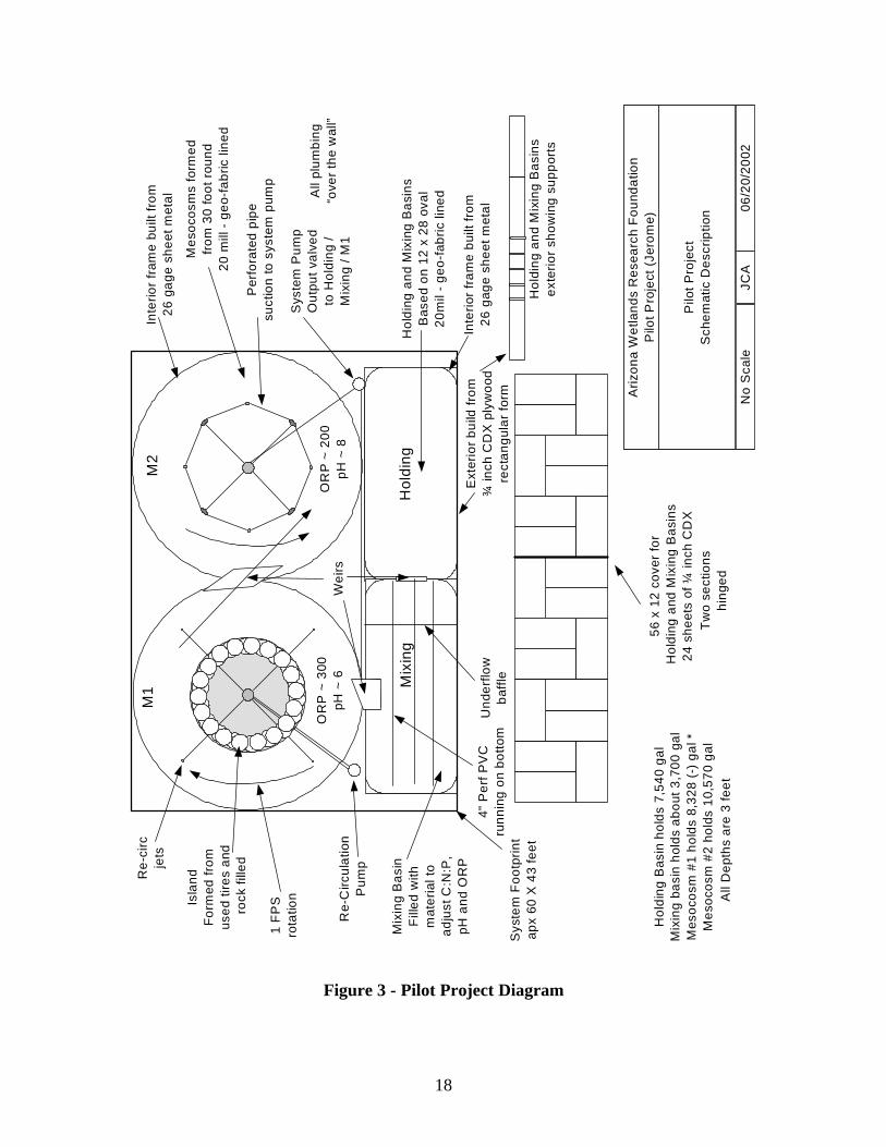
Please refer to the Pilot Project Schematic in the appendix.

5
A Mesocosm is a term that describes one type of microcosm that is primarily used to test aquatic organisms inside of an enclosed system. Mesocosms are a model ecosystem, which is used to miniaturize and replicate the real thing. Mesocosms are used because they allow ecosystem replication and manipulation. The Mesocosm provides sufficient area for observations, sampling, and housing of a large variety and quantity of species. Mesocosms also provide sufficient size as to model the real ecosystem. Mesocosms can either use artificial or natural waters for studying.
DESIGN THEORY
The Holding Tank supplies system ballast. This tank needs to be as large as possible in relation to the volume of the Mesocosms. The Mixing Tank allows for C:N:P and ORP/pH modification. The identification of materials to provide this modification is one of the objectives of the Pilot Project. Initial findings indicate that Acid Mine Drainage may be a highly suitable material for ORP and pH adjustment. The design of the Mixing Tank must allow for sufficient flexibility in material addition and modification. It is possible that waters may be found that are problematic in only one constituent such as N. In this case the scope of the influent adjustment must also insure that water constituents such as C, N and P are in a balance that is usable by the biological environment (Redfield Ratio). It was decided that a partitioned tank would allow for the maximum flexibility. The partition will form a “clean” and a “mix” section separated by an underflow baffle. The “mix” side will be filled with material selected to accomplish the ORP, pH, C:N:P modification.
The Mesocosms provide the growing environment for the periphyton. Research indicates that nutrient uptake will be facilitated by separating the two basic biological processes: the high metabolism, high ORP / low pH environment most suited to NO3, P and Heavy Metal removal; and the low metabolism, low ORP / high pH environment most suited to Nitrification / Denitrification. The high ORP / low pH environment is usually found in quick-running stream structures and the low ORP / high pH environment is usually found in pond like structures. Because of this a two Mesocosm system was selected. The Mesocosms will be formed as circular tanks. The first Mesocosm (Mesocosm #1) will be designed to resemble a small, fast flowing stream. This will be accomplished by building an island in the center of the Mesocosm. The second Mesocosm (Mesocosm #2) will be designed to resemble a small lake bottom. The metabolic process of periphyton lowers OPR and raises pH. Thus the biological process in Mesocosm #1 prepares the water for Mesocosm #2.
The Support Plumbing provides all the pumps and pipes necessary to circulate and re-circulate water as needed within the Pilot Project. The Support Plumbing must provide the following functionality:
1. It must provide the initial System Flow. 2. It must provide Mesocosm #1 re-circulation.

6
S YSTEM FLOW
System Flow is defined as the basic flow through the system. System Flow represents the “new” water being added to the process. Thus System Flow to a great extent defines detention time. The targeted upper limit to System Flow is 55 gpm. It is desired that flow from tank to tank be gravity driven. Therefore the hydraulic connections between the Holding, Mixing, and Mesocosm Tanks will be formed using a series of “stair-step” weirs between these tanks to allow for flow based on an elevated water level in the upstream tank. System Flow is initiated by pumping water from the last Mesocosm (Mesocosm #2) to the Holding Tank. This will provide the initial elevation necessary to flow water through the Pilot Project. There is an additional requirement that there be a great deal of flexibility in the direction of the flow pumped from the final Mesocosm. For this reason a valve manifold will be required such that this flow can be directed, in proportion, to any of the tanks within the Pilot Project. The System Pump will be a constant speed pump. To allow for System Flow to be reduced below the 55 gpm provided by the System Pump, pipe and valves would be needed to feed a portion of the pump output back into the input of the pump. Additionally there is the requirement that the piping support a backwash operation.
MESOCOSM #1 RE-CIRCULATION FLOW
Mesocosm #1 re-circulation flow will be accomplished by pumping water from Mesocosm #1 back into the Mesocosm through a set of 4 hydro-jets spaced equidistant around the bottom of the flow channel. As with the System pump, the Mesocosm #1 re-circulation pump is a constant speed pump. Therefore it will require the same flow reduction valves described in the System Flow section. This pump will also support back flush.
VARIABLES
Management of system variables will be key to the success of the Pilot Project. The following are the identified variables and what may be done to influence them:
ORP/pH - proportional adjustment of System Flow C:N:P - proportional adjustment of System Flow M1 Recirculation - proportional adjustment of recirculation at pump M1 Detention - proportional adjustment of System Flow M2 Detention - proportional adjustment of recirculation to M2 Periphyton Density - harvesting
MESOCOSM DESIGN
The size of the Mesocosms was dictated be the area available to the Pilot Project. This area is approximately 60 X 40 feet. This allows the use of 30 ft pools as Mesocosms.

7
Mesocosm #1 will be a 30 ft pool with a 15 ft. island in the center. The island is to be built using used tires and aggregate filled. This results in a 7.5 ft. circular flume with a mean diameter of 11.25 ft and a circumference of (apx) 35 ft. This flume will be filled with .5 ft aggregate and 2.5 ft. water. Discounting the water in the aggregate, this channel holds (apx) 7,900 gal. The current targeted System Flow is 55 gpm. This gives a basic detention time of (apx) 142 minutes. The targeted recirculation is 1 FPS, which results in a rotational period of (apx) 35 seconds, or (apx) .6 minutes (for mean circumference). Correlating the rotational period with the detention time gives (apx) 237 rotations per detention period. The combination of detention period and recirculation results in the equivalent of a “river” 8,295 ft. or 1.6 miles in length. This circular flume will be populated with the epiphyton (plant) forms of periphyton. Epiphyton resemble seaweed and long grasses. The re-circulating water will flow through this periphyton mass. The ratio of periphyton mass to water volume is unknown at this time. As the periphyton mass will reduce the water volume, the final straight-flume equivalent will be somewhat less than the idealized numbers.
The first Mesocosm (Mesocosm #1) will contain a high ORP / low pH environment most conducive to epiphyton (plant) type growth. It is expected that much of the P removal will occur in Mesocosm #1, as well as substantial heavy-metal removal.
The diameter of the Mesocosm #2 will be the same as that of Mesocosm #1. However, the contour of Mesocosm #2 will be quite different than that of Mesocosm #1. Where Mesocosm #1 took the form of a stream like flume, Mesocosm #2 will be more pond like in nature. The pond like structure is required because the periphyton mass in Mesocosm #2 will be of the epilithon (rock) and epilelon (mud) forms. These are low metabolism life forms. The bottom of Mesocosm #2 will be concave in shape and built of aggregate material. The aggregate material will provide ample surface area for the periphyton to colonize. This results in a detention volume of (apx) 8,908 gallons in Mesocosm #2. System Water flow within Mesocosm #2 will be drawn through the aggregate by the System Pump insuring maximum contact with the biota. Additionally there will be provisions within the System Pump and Piping to re-circulate water back to Mesocosm #2 to increase detention time.
The second Mesocosm (Mesocosm #2) will contain a low ORP / high pH environment most conductive to epipelon (mud) type growth. It is expected that much of the Nitrification / Denitrification process will occur in Mesocosm #2. While the Nitrification / Denitrification process is normally described as an anaerobic (absence of Oxygen) process, this is not 100% descriptive of the required environment. A better term would be anoxic (low Oxygen). This anoxic environment is established at an ORP level of 200 or less [1].
Because of the re-circulating nature of the water in the Mesocosms, there should be an inherent efficiency over linear flows due to the constant rate of the re-circulating flow within the Mesocosm versus the varied rate of linear flow in non-pressurized channels. Additionally a re-circulating flow has the advantages of longer contact time and greater contact probability with the periphyton. In linear flow systems the constituents are substantially higher at the beginning of the flow, with periphyton population falling off as flow progresses through the linear system. To accomplish the re-circulation, the Pilot Project will include pumps in order add velocity to the re-circulating flows. This is necessary due to the small gravity gradient of the Pilot Project. In projects where a larger

8
gravity gradient exists, it may be possible to accomplish this re-circulation through flow channeling.
CONSTRUCTION
In general, the Pilot Project will closely resemble a collection of “Above Ground” swimming pools. The Pilot Project will be built above ground. The Pilot Project will be constructed in a manner that meets or exceeds those materials and methods used in commercial “Above Ground” swimming pools. The walls of the tanks will be fabricated by riveting 4 x 10 ft sheets of 26 gauge sheet metal to form the exterior wall. A 6 in. “cove wall” will be formed at the base of the wall. The tanks and Mesocosms will be double lined with 20 mil PVC liner due to nature of the water they contain. The top and bottom of the walls will be fitted with channel rails to increase rigidly. All tanks will allow for 1 ft of head space above nominal water levels. All tanks will be fitted with over-level floats for pump shutdown. The Holding, Mixing, Mesocosm #1, and Mesocosm #2 tanks will be connected by weirs formed from key-stone cuts made in the sheet-metal to form the stair-step weirs. These cuts will be riveted together and made watertight. The stair-step increment is to be 1 in. Thus the nominal water level of Mesocosm #2 is three (3) inches below the nominal water level of the Holding Tank.
TANKS AND MESOCOSMS
The Holding and Mixing Tanks will be lumber framed and will be covered. The lumber framing will support the walls of these tanks and the cover. The cover will reduce evaporation from these tanks.
The Mixing Tank will be constructed in two sections, separated by an underflow baffle. The baffle will separate the Mixing Tank into two segments; a “clean” segment and a “mixing” segment. Four lengths of 4 in perforated pipe will run from the underflow baffle across the bottom of the “mix” side of this tank. Water elevation differential between the “clean” and “mix” side of the underflow baffle will cause the water to flow up through and come in contact with the material in the Mixing Tank.
The Mesocosms walls will be supported by 16 pieces of ¾ in rebar equally spaced around the circumference of the Mesocosms and set 1 ft in the ground. This rebar will be attached to the sheet metal wall. The island in Mesocosm #1 will be formed from used tires and filled with aggregate. A 2 in perforated pipe will be embedded in the island to provide input to the re-circulation pump. Perforated pipe will be embedded in the aggregate bed of Mesocosm #2 to provide input to the System Pump.
The Mesocosms will be filled with aggregate to form the flow channels and provide a substrate upon which the periphyton will grow. Once the Mesocosms have been built and the aggregate installed, flow studies will be performed that will identify areas where the flow is problematic. Aggregate will be moved as necessary to insure that inter and intra-Mesocosm flows are behaving in a desired manner. Once the flow observations and corrections have been performed the Mesocosms will be populated with the initial periphyton colony.
The initial periphyton population will be undifferentiated as to species. It is expected that as the periphyton colony in Mesocosm #1 becomes established it will adjust

9
the ORP and pH of the water flowing into Mesocosm #2. This in turn will cause the periphyton colony in Mesocosm #2 to become predominated by species adapted to that environment. Thus as the Pilot Project runs the periphyton colonies in the two Mesocosms will become more and more differentiated until only those species most suited for these two environments will predominate.
PUMPS AND PIPES
System Plumbing is comprised of two (2) pumping and plumbing sub-systems. The sub-systems are: System Pump and Pipe Recirculation Pump and Pipe
The action of the System Pump and Pipe will be to draw water from Mesocosm #2, which will be the basis of system flow. Influent to the System Pump will be from a field of perforated pipe buried within the aggregate in Mesocosm #2. Effluent from the System Pump will be primarily directed to the Holding Tank, however there will be valving to allow the effluent of the System pump to be directed to the Mixing Tank, Mesocosm #1 and / or Mesocosm #2 in a flow proportional mode. This will allow for fine-tuning system flow rates, and thus detention times. Additionally, the valving will allow for back flushing the perforated pipe.
The action of the Recirculation Pump and Pipe will be to draw water from Mesocosm #1 and reintroduce that water via jets into the Flow Channel area of Mesocosm #1. Influent to the Recirculation pump will be from a perforated pipe buried within the island of Mesocosm #1. Effluent from the Recirculation Pump will be primarily to the Recirculation Jets within Mesocosm #1, however there will be valving to allow effluent of the Recirculation Pump to be returned to the influent side of the Recirculation Pump to allow for recirculation rate adjustment. Additionally, the valving will allow for back flushing the perforated pipe.
All pipes in the Pilot Project will be 2 in, schedule 40 PVC. All pumps used in the Pilot Project will be off-the-shelf swimming pool pumps rated at 55 GPM.
METHODOLGY
OPERATIONS Drawing #1 illustrates the process flow of the Pilot Project.
HoldingMixing
Mesocosm #1 Mesocosm #2
Drawing #1

10
o System Water is held in the Holding Tank. System Water will be pumped from
Mesocosm #2 back to the Holding Tank, creating the basic system flow. o System Water gravity flows over a weir into the Mixing Tank based on an
increased water level in the Holding Tank. o System Water flows up through the adjustment material in the Mixing Tank based
on water level equalization between areas separated by the under-flow baffle. o System Water gravity flows into the first Mesocosm over a weir based on
increased water level in the Mixing Tank. System Water re-circulates within the Mesocosm at a velocity of approximately 1 FPS, and is acted upon by the first colony of periphyton. The detention time in the first Mesocosm is dictated by the System Water flow rates and size of the Mesocosm. Detention time will be modified to insure that effluent from the Mesocosm shows an appropriate elevation in pH with a corresponding decrease in ORP.
o System Water gravity flows into the second Mesocosm, over a weir based on increased water level in Mesocosm #1. System Water circulates and is drawn down through a rock bed by the action of the System Pump. Within the rock bed, the System Water is acted upon as in the first Mesocosm. The periphyton in the second Mesocosm will be of a different species set than that of the first Mesocosm. The species set of the second Mesocosm will be those more suited to the lower ORP and higher pH environment found there.
ACTIONS
Much of the controlling actions that can be placed on the Pilot Project will be done by valve position modification on the System Pump Valve Manifold. The following diagrams show three of the many valve position setting.
Holding
M2 R
ecycle
M1
Mixing
Forward
Reverse
Pressure
Mesocosm #2 - Perforated Pipe
Mesocosm #2 - backwash draw
Backwash / Recycle
The first configuration shows a “normal” operations mode. In this configuration the System Pump input valve selection is to the perforated pipe in the Mesocosm #2 aggregate bed. The Backwash / Recycle valve selection in the 100% Forward position. The Holding Tank valve is 100% open. In this configuration the System Flow is as specified in the Operations section, above.

11
Holding
M2 R
ecycle
M1
Mixing
Forward
Reverse
Pressure
Mesocosm #2 - Perforated Pipe
Mesocosm #2 - backwash draw
Backwash / Recycle
In the second configuration, we see the valve position settings for a backwash operation. In this configuration the System Pump input valve selection is to the backwash draw located outside the aggregate bed. The Backwash / Recycle valve selection is in the 100% Reverse position.
Holding
M2 R
ecycle
M1
Mixing
Forward
Reverse
Pressure
Mesocosm #2 - Perforated Pipe
Mesocosm #2 - backwash draw
Backwash / Recycle
In the third configuration, we see one of the many operating modes supported by this valve layout. In this configuration the System Pump input valve selection is to the perforated pipe in the Mesocosm #2 aggregate bed. The Backwash / Recycle valve selection is set to 50% Recycle. This reduces flow to about 27 GPM. The Holding Tank and the Mesocosm #2 Recycle valves are set to 50%. This directs about 14 GPM back to Mesocosm #2 (increasing detention time) and 14 GPM being sent to the Holding Tank. In configurations such as these special attention is made to the pump pressure to insure that it is under 10 psi. Pump and valve configuration changes will be noted on the Data Logging Form, figure 2, appendix.
MONITORING PROGRAM
The Pilot Project requires a significant monitoring process. During the operation of the Pilot Project, the following water constituents will be monitored;
What via 1. Nitrogen (NH3, NO2, NO3) Photometry 2. Phosphorous (PO4) Photometry 3. Dissolved Oxygen (DO) Photometry
12
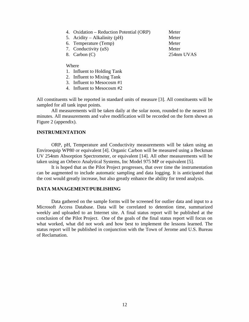
4. Oxidation – Reduction Potential (ORP) Meter 5. Acidity – Alkalinity (pH) Meter 6. Temperature (Temp) Meter 7. Conductivity (uS) Meter 8. Carbon (C) 254nm UVAS Where 1. Influent to Holding Tank 2. Influent to Mixing Tank 3. Influent to Mesocosm #1 4. Influent to Mesocosm #2
All constituents will be reported in standard units of measure [3]. All constituents will be sampled for all tank input points.
All measurements will be taken daily at the solar noon, rounded to the nearest 10 minutes. All measurements and valve modification will be recorded on the form shown as Figure 2 (appendix).
INSTRUMENTATION
ORP, pH, Temperature and Conductivity measurements will be taken using an Enviroequip WP80 or equivalent [4]. Organic Carbon will be measured using a Beckman UV 254nm Absorption Spectrometer, or equivalent [14]. All other measurements will be taken using an Orbeco Analytical Systems, Inc Model 975 MP or equivalent [5].
It is hoped that as the Pilot Project progresses, that over time the instrumentation can be augmented to include automatic sampling and data logging. It is anticipated that the cost would greatly increase, but also greatly enhance the ability for trend analysis.
DATA MANAGEMENT/PUBLISHING
Data gathered on the sample forms will be screened for outlier data and input to a Microsoft Access Database. Data will be correlated to detention time, summarized weekly and uploaded to an Internet site. A final status report will be published at the conclusion of the Pilot Project. One of the goals of the final status report will focus on what worked, what did not work and how best to implement the lessons learned. The status report will be published in conjunction with the Town of Jerome and U.S. Bureau of Reclamation.

13
PARTS LIST PRICES
14
REFERENCES ACID MINE DRAINAGE: An Example of Microbial Ecology in Action, BGY C55S -
Microbes in the Environment, Lecture #13, University of Toronto http://citd.scar.utoronto.ca/BGYC55/C55-2000-L13-web.htm
Algal Research Projects: Dr John Kinross, School of Life Sciences, Naiper University,
Edinburgh http://www.lifesciences.napier.ac.uk/courses/postgrad/jkweb/jkfiles/alg-res.htm
Constituent Name (units of measure), USGS
http://water.usgs.gov/pubs/dds/wqn96cd/html/report/indx3.txt ENVIROEQUIP: TPS WP80 & WP80D pH, redox, temperature meters
http://enviroequip.com/sales/tpswp80.htm Orbeco Analytical Systems, Inc: Model 975 MP
http://www.orbeco.com/prodPages/analyst.html Periphyton Filtration: An Economically and Environmentally Sustainable Phosphorus
Removal Engine, Jenson, Kyle. Science Applications Incorporated http://www.ces.fau.edu/library/flms/25.html
Phosphorus Removal from Agricultural Runoff: An Assessment of Macrophyte and
Periphyton-Based Treatment Systems, T.A. DeBusk, J.E. Peterson, K.R. Jensen http://www.agen.ufl.edu/~klc/wetlands/debusk.htm
Phosphorus removal from wastewater using an algal turf scrubber, Rupert J. Craggs*,
Walter H. Adey**, Kyle R. Jenson***, Matthais S. St. John*, F. Bailey Green* and William J. Oswald*, Water Science and Technology Vol 33 No 7 pp 191–198. http://www.iwaponline.com/wst/03307/wst033070191.htm
Real-time control of nitrogen removal using three ORP bending-points: signification,
control strategy and results, S. Plisson-Saune*, B. Capdeville*, M. Mauret*, A. Deguin** and P. Baptiste, Water Science and Technology Vol 33 No 1 pp 275–280. http://www.iwaponline.com/wst/03301/wst033010275.htm
Total Maximum Daily Load (TMDL) Program, Nutrients and Water Quality, U.S.
Environmental Protection Agency, Office of Water http://www.epa.gov/owow/tmdl/nutrient/wat-qual.html
Using fish and periphyton for P and N removal, R. Drenner, D. Day, S. Basham, J.
Durward Smith, Biology Dept., Texas Christian University http://www.ceep-phosphates.org/scope/articles/scope32/scope32-10.htm

15
Periphyton response to nitrogen and phosphorus additions in the Florida Everglades.
Vymazal, J., C.B. Craft, and C.J. Richardson. 1994. Algological Studies 73:75-79. http://www.env.duke.edu/wetland/vym_94_algo.htm
Phytoplankton and the Biological Pump, U.S. National Report to IUGG, 1991-1994, Rev. Geophys. Vol. 33 Suppl., © 1995 American Geophysical Union.
http://www.agu.org/revgeophys/chisho00/node2.html MISCELLANEOUS INSTRUMENTAL METHODS - METHODS USING INFRARED
ANALYSIS - UV Absorbance (254 nm) to DOC Regression Equations http://www.ecs.umass.edu/cee/reckhow/courses/572/572bk22/572BK22.html

16
Appendix A. Figures and Data Sheets
Figure 1 - ORP (eh) v. pH and biological reaction zones

17
Figure 2 - Sample Data Logging Form
Date:
Solar Noon
Weather
Influent to Holding Tank
NH3 NO2 NO3
PO4 DO
ORP pH Temp
uS C
Influent to Mixing Tank
NH3 NO2 NO3
PO4 DO
ORP pH Temp
uS C
Influent to Mesocosm #1
NH3 NO2 NO3
PO4 DO
ORP pH Temp
uS C
Influent to Mesocosm #2
NH3 NO2 NO3
PO4 DO
ORP pH Temp
uS C
Notes:
18
Figure 3 - Pilot Project Diagram
Ext
erio
r bu
ild fr
om¾
inch
CD
X p
lyw
ood
rect
angu
lar
form
Inte
rior
fram
e bu
ilt fr
om26
gag
e sh
eet m
etal
Inte
rior
fram
e bu
ilt fr
om26
gag
e sh
eet m
etal
Hol
ding
and
Mix
ing
Bas
ins
exte
rior
show
ing
supp
orts
Re-
Circ
ulat
ion
Pum
p
M1
M2
Hol
ding
and
Mix
ing
Bas
ins
Bas
ed o
n 12
x 2
8 ov
al20
mil
- ge
o-fa
bric
line
d
56 x
12
cove
r fo
r H
oldi
ng a
nd M
ixin
g B
asin
s24
she
ets
of ¼
inch
CD
X
Mes
ocos
ms
form
edfr
om 3
0 fo
ot r
ound
20 m
ill -
geo
-fab
ric li
ned
All
plum
bing
“ove
r th
e w
all”
Sys
tem
Pum
pO
utpu
t val
ved
to H
oldi
ng /
Mix
ing
/ M1
All
Dep
ths
are
3 fe
et
Hol
ding
Bas
in h
olds
7,5
40 g
alM
ixin
g ba
sin
hold
s ab
out 3
,700
gal
Mes
ocos
m #
1 ho
lds
8,32
8 (-
) ga
l *M
esoc
osm
#2
hold
s 10
,570
gal
Sys
tem
Foo
tprin
tap
x 60
X 4
3 fe
et
Re-
circ
jets
Mix
ing
Bas
inF
illed
with
mat
eria
l to
adju
st C
:N:P
,pH
and
OR
P
Und
erflo
wba
ffle
Wei
rs
Per
fora
ted
pipe
suct
ion
to s
yste
m p
ump
Isla
ndF
orm
ed fr
omus
ed ti
res
and
roc
k fil
led
4" P
erf P
VC
runn
ing
on b
otto
m
1 F
PS
rota
tion
bale
Tw
o se
ctio
nshi
nged
Mix
ing
Hol
ding
OR
P ~
300
pH ~
6O
RP
~ 2
00pH
~ 8
Ariz
ona
Wet
land
s R
esea
rch
Fou
ndat
ion
Pilo
t Pro
ject
(Je
rom
e)
No
Sca
le
Pilo
t Pro
ject
Sch
emat
ic D
escr
iptio
n 06/2
0/20
02JC
A