Embed Size (px)
Citation preview

Rapid Design of an optimized Radial Compressor
using CFturbo and ANSYS
Enrique Correa, Marius Korfanty, Sebastian Stübing
CFturbo Software & Engineering GmbH, Dresden (Germany)

PRESENTATION TOPICS
1. Company overview
2. Aerodynamic compressor design
3. Automated simulation process
4. Results
5. Conclusion and next steps

1. Company overviewFields of activity
CFturbo® Software & Engineering GmbH (Germany)
CAE Consulting CAD & Prototyping
• Turbomachinery
conceptual design
• CFD/FEA simulation
• Optimization
• 3D-CAD modeling
• Prototyping
(with partners)
CFturbo® Software
• Design software for
turbomachinery
• Training courses
• Workflows

1. Company overviewSoftware customers (extract)

2. Aerodynamic compressor designWhat is CFturbo?
CFturbo = conceptual turbomachinery design (radial, mixed-flow, axial)
for impellers, stators and volutes
CFturbo®
New / improved3D geometry
Fundamental fluid equationsEuler's equation of turbom.,
Continuity,Momentum equation,
Velocity triangles, …
Empirical functionsPublicly available experiences,
In-house know-How Geometry import, redesign optionally
Machine design pointm, H/Δp, n,
Fluid properties,Inlet boundary conditions
High geometrical flexibility, many checks, information

2. Aerodynamic compressor designCFturbo input
Design point
• Total pressure ratio tt = 4
• Mass flow ṁ = 0.11 kg/s
• Rotational speed n = 90 000 RPM
• Max. motor power PM < 30 kW
• Max. available power Pi = 25.5 kW
Constraints
• Max. casing extension
• Manufacturing by flank milling

2. Aerodynamic compressor designCFturbo design steps
Impeller
Main dimensions Meridian contour Blade properties Mean lines Blades edges
Volute
Cross section Spiral areas Diffuser, Cutwater
General
Meridian view 3D-Model

2. Aerodynamic compressor designCFturbo design steps
Design step
example

2. Aerodynamic compressor designComponents
Volute
Impeller
Diffuser
Assembly

3. Automated simulation processOverview
Conceptual DesignCFturbo
Grid generationANSYS ICEM-CFD
ProductOptimization
interactive or automatic
SimulationANSYS CFX
Design point,requirements

3. Automated simulation processMeshing in ICEM-CFD
Export in CFturbo
ICEM-CFD parameters in CFturbo

3. Automated simulation processMeshing in ICEM-CFD
CFturbo2ICEM panels in ICEM-CFD

3. Automated simulation processMeshing in ICEM-CFD
• Fully automated, script based meshing with Tet/Prism, Hexa
• Mesh size: 4.6 Mill. nodes
• Design modifications and meshing within 1 hour

3. Automated simulation processCFX settings
Inlet pipe
Impeller
Volute
Radial diffuser
Outlet pipe
• Steady-state simulations
(Frozen-Rotor model)
• Transient simulation
for final model
• SST turbulence model
INLET:
Total pressure
OUTLET:
Mass flow

4. ResultsImpeller and Volute
Static pressure Velocity

4. ResultsImpeller
Static pressure (mid-span) (blade-to-blade) (meridian)

4. ResultsPerformance map
90 000 RPM
97 000 RPM
94 000 RPM
92 000 RPM
90 000 RPM86 000 RPM

4. ResultsPrototype

5. Conclusion and next steps
• CFD based design procedure for compressor stage
- comfortable, easy-to-use
- reliable results
- very fast design and analysis
• 10 different compressors designed to get best compromise between
efficiency, power requirements and geometrical constraints
• Project was running within 4 weeks
• Stage efficiency ηSt = 67 %
Impeller efficiency ηImp = 84 %
Power consumption Pi = 25 kW
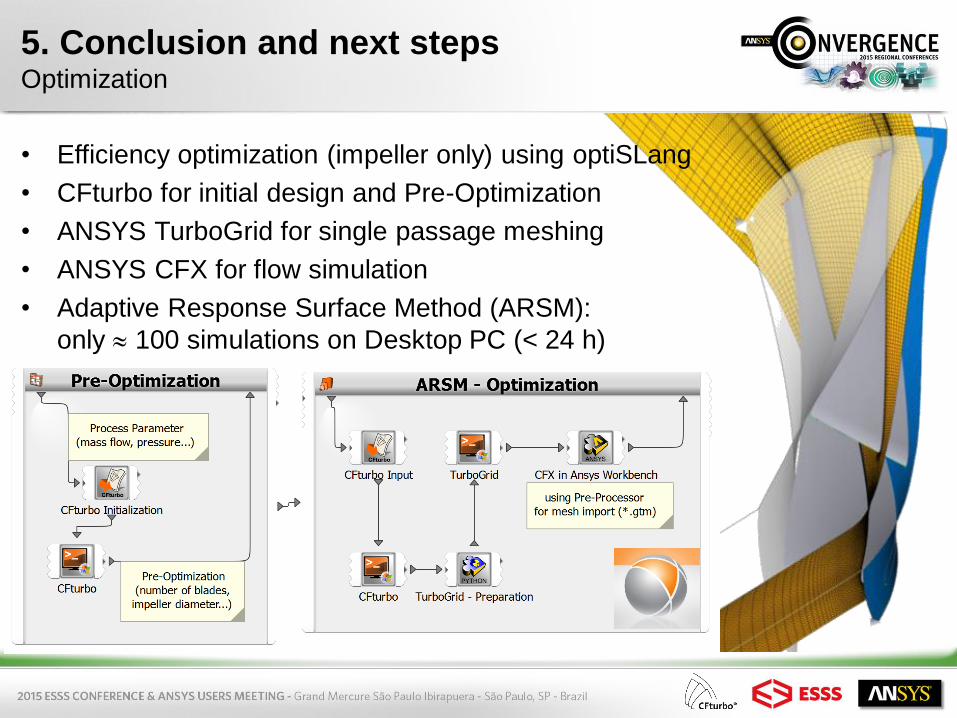
5. Conclusion and next stepsOptimization
• Efficiency optimization (impeller only) using optiSLang
• CFturbo for initial design and Pre-Optimization
• ANSYS TurboGrid for single passage meshing
• ANSYS CFX for flow simulation
• Adaptive Response Surface Method (ARSM):
only 100 simulations on Desktop PC (< 24 h)

5. Conclusion and next stepsOptimization
Initial design: ηImp = 78 % Optimized design: ηImp = 84.5 %
… will be
continued for the
whole compressor
stage …