Embed Size (px)
Citation preview

1
Rapid CW400 Batching System
User Manual
Pneutrol International Limited,
5 Caulside Drive,
Antrim, Co. Antrim, N. Ireland.
TEL: +44 (0) 28 9448 1800
FAX: +44 (0) 28 9448 1801
18/03/2015
2
Contents
1: GENERAL INFORMATION .......................................................................................................... 3
1.1: System Hardware ...................................................................................................................... 3 1.2: System Software Standard Features.......................................................................................... 4
2: SYSTEM SET-UP ........................................................................................................................... 5 2.1: Standard Navigation bar: .......................................................................................................... 6
3: RUNNING INFORMATION: ......................................................................................................... 7 3.1 Running Screen – Manual Controls: .......................................................................................... 9
4: STATISTICS: ................................................................................................................................ 11
4.1: Production Summary: ............................................................................................................. 12 4.2: Stock: ...................................................................................................................................... 13 4.3: Trucks: .................................................................................................................................... 14 4.4: Drivers: ................................................................................................................................... 15 4.5: Delivery Supplier: ................................................................................................................... 16
5: RECIPE SCREEN: ........................................................................................................................ 17 5.1: View/Edit Recipes: ................................................................................................................. 18
5.1.1: Calibrate Recipes: ............................................................................................................ 19 5.2: Recipe Groups:........................................................................................................................ 23
6: CUSTOMERS: .............................................................................................................................. 24 7: SETUP: .......................................................................................................................................... 25
7.1: Plant Setup: ............................................................................................................................. 26 7.1.1: General Variables: ........................................................................................................... 27 7.1.2: Drives: .............................................................................................................................. 28
7.1.3: Times: .............................................................................................................................. 29 7.1.4: Drain Times: .................................................................................................................... 30
7.1.5: Alarm Times: ................................................................................................................... 31 7.1.6: Tolerances: ....................................................................................................................... 32 7.1.7: Rates:................................................................................................................................ 33
7.1.8: Cement Refill Control: ..................................................................................................... 34 7.1.9: Analogs: ........................................................................................................................... 35
7.2: Material Setup: ........................................................................................................................ 36 7.3: Supplier Setup: ........................................................................................................................ 37
7.4: Printer Setup: .......................................................................................................................... 38 7.5: IO Status: ................................................................................................................................ 39
7.6: Users: ...................................................................................................................................... 40 8: HISTORICAL CHART: ................................................................................................................ 41 9: REAL-TIME FLOWS CHART: .................................................................................................... 42
10: REAL-TIME WEIGHERS: ......................................................................................................... 43 11: REAL-TIME DRIVES: ............................................................................................................... 44
12: DIAGNOSTICS/ALARMS: ........................................................................................................ 45 12.1: Alarms Screen: ...................................................................................................................... 45
13: REMOTE ACCESS: .................................................................................................................... 46
14: SHUTDOWN SYSTEM: ............................................................................................................. 46
15: USEFUL INFORMATION: ........................................................................................................ 47 15.1: Pausing The System: ............................................................................................................. 47 15.2: Emergency Stop: ................................................................................................................... 47
15.3: What To Do If You Have A Problem? ................................................................................. 47 16: APPENDIX 1 – Cement Weigh Hopper Calibration:.................................................................. 48 17: APPENDIX 2 – Aggregate Weigh Hopper Calibration: ............................................................. 49 18: APPENDIX 3 – Best Practise/Regular Checks ........................................................................... 50 19: APPENDIX 4 – Full Alarm List .................................................................................................. 51
3
1: GENERAL INFORMATION The Control System and Software have been designed and developed specifically for the control of
Concrete Batching Plants. The Hardware that is housed inside our Control Panel has been chosen
for its reliability in operation and for flexibility in different applications.
The software is 'Customised' for each plant and is therefore suitable for all types of plants and
plant layouts.
1.1: System Hardware
CONTROLLER: - ALLEN BRADLEY Micrologix Processor.
- Uses Industry Standard Ladder Logic Programs.
- CSA Certification to Class 1 Division 2.
- Battery-backed up memory for protection of program and data.
- Can be expanded to take in 256 additional discrete I/O - Built-in LCD with backlight allows you to view controller and I/O status
TERMINAL: - Exor eTOP 15” touch screen operator interface
- 16.2M colours, providing XGA 1024x768resolution display
- Energy efficient LED display - Displays all plant data.
- Displays plant operation on screen.
PRINTER: - Able Systems Ltd Ap1400V Thermal Panel Printer
- Robust design with added protection for harsh environments
- Mechanism life of 13 million print lines - Print speed of 80mm/sec
- Flexible connectivity
4
1.2: System Software Standard Features
1. STORAGE OF RECIPES: Each recipe will contain the details regarding a specific batch, which
is the amount of each of the aggregates, cement, water and additives if required. There is no limit
to the number of recipes the system can store.
2. PASSWORD PROTECTION: Information in the memory of the computer can be protected by a
password code to prevent any unauthorised person changing or resetting recipes, batching
controls, stock, etc.
3. AUTOMATIC ZEROING: Auto zeroing (aggregate only) between weighments is carried out so
that accumulative weighing errors are avoided.
4. STOCK CONTROL: Materials in stock and material usage are stored in memory on the HMI.
These may be displayed as required to give daily or monthly totals for each material used in the
plant and stock levels remaining.
5. NO FEED: Should a bin be empty or material be bridged in the bin then an alarm message will
be given.
6. PRINTER: The printer will record batches produced and a printout will be given after each
batch with details of material produced.
7. PLANT ALARMS: An alarm message will be displayed on the monitor and a printout will be
given of the alarm fault together with a date and time.
Alarm messages are given for specific faults e.g.
‘Mixer not running’
The operator may therefore rectify the problem quickly and so save on plant 'Down Time'.
An audible and/or visual alarm is also available where the operator may be a considerable
distance from the Control Panel.
Once the alarm has been initiated the operator may push the alarm accept button at the control
panel once to cancel the audible/visual alarm. He must then push the alarm accept button again
to continue batching once the fault has been rectified. Also the operator may rectify an alarm
when in the alarm screen using option "F1: ACCEPT ALARMS".
9. MONITOR:
Displays Selection Menus.
Displays recipes
Displays batching tolerances Displays alarms
Displays plant Inputs and Outputs.
Displays running screen.
Displays a variety of stock and production reports
Displays customer information
5
2: SYSTEM SET-UP
When the generator is started, the UPS and HMI will automatically be turned on. During the course of normal use, if the HMI is not being used, it will automatically go into sleep mode, there
is a small LED in the top right hand side of the HMI, the various LED’s alert the suer to the
following:
Red – Power is on, but the HMI is turned off
Amber – Power is on, but the HMI is in sleep mode Green – Power is on and the HMI is on
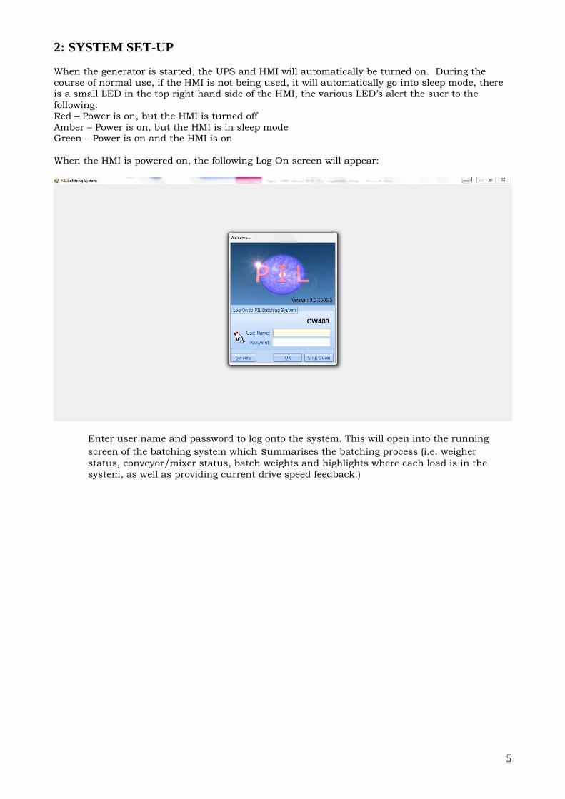
When the HMI is powered on, the following Log On screen will appear:
Enter user name and password to log onto the system. This will open into the running
screen of the batching system which summarises the batching process (i.e. weigher
status, conveyor/mixer status, batch weights and highlights where each load is in the
system, as well as providing current drive speed feedback.)
6
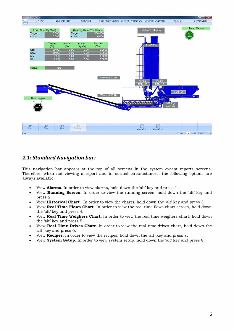
2.1: Standard Navigation bar:
This navigation bar appears at the top of all screens in the system except reports screens.
Therefore, when not viewing a report and in normal circumstances, the following options are
always available:
View Alarms. In order to view alarms, hold down the ‘alt’ key and press 1.
View Running Screen. In order to view the running screen, hold down the ‘alt’ key and press 2.
View Historical Chart. In order to view the charts, hold down the ‘alt’ key and press 3.
View Real Time Flows Chart. In order to view the real time flows chart screen, hold down the ‘alt’ key and press 4.
View Real Time Weighers Chart. In order to view the real time weighers chart, hold down the ‘alt’ key and press 5.
View Real Time Drives Chart. In order to view the real time drives chart, hold down the ‘alt’ key and press 6.
View Recipes. In order to view the recipes, hold down the ‘alt’ key and press 7.
View System Setup. In order to view system setup, hold down the ‘alt’ key and press 8.
7
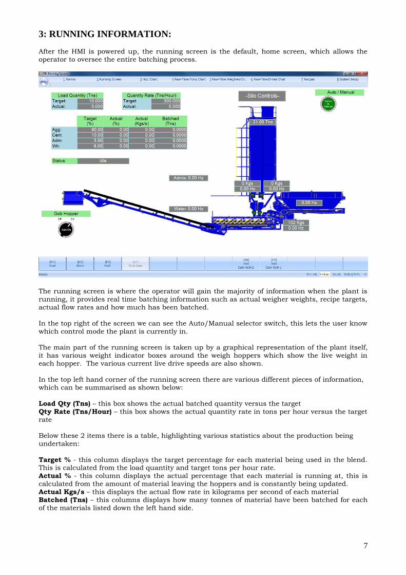
3: RUNNING INFORMATION:
After the HMI is powered up, the running screen is the default, home screen, which allows the operator to oversee the entire batching process.
The running screen is where the operator will gain the majority of information when the plant is
running, it provides real time batching information such as actual weigher weights, recipe targets,
actual flow rates and how much has been batched.
In the top right of the screen we can see the Auto/Manual selector switch, this lets the user know
which control mode the plant is currently in.
The main part of the running screen is taken up by a graphical representation of the plant itself,
it has various weight indicator boxes around the weigh hoppers which show the live weight in
each hopper. The various current live drive speeds are also shown.
In the top left hand corner of the running screen there are various different pieces of information,
which can be summarised as shown below:
Load Qty (Tns) – this box shows the actual batched quantity versus the target
Qty Rate (Tns/Hour) – this box shows the actual quantity rate in tons per hour versus the target
rate
Below these 2 items there is a table, highlighting various statistics about the production being
undertaken:
Target % - this column displays the target percentage for each material being used in the blend. This is calculated from the load quantity and target tons per hour rate.
Actual % - this column displays the actual percentage that each material is running at, this is
calculated from the amount of material leaving the hoppers and is constantly being updated.
Actual Kgs/s – this displays the actual flow rate in kilograms per second of each material
Batched (Tns) – this columns displays how many tonnes of material have been batched for each
of the materials listed down the left hand side.
8
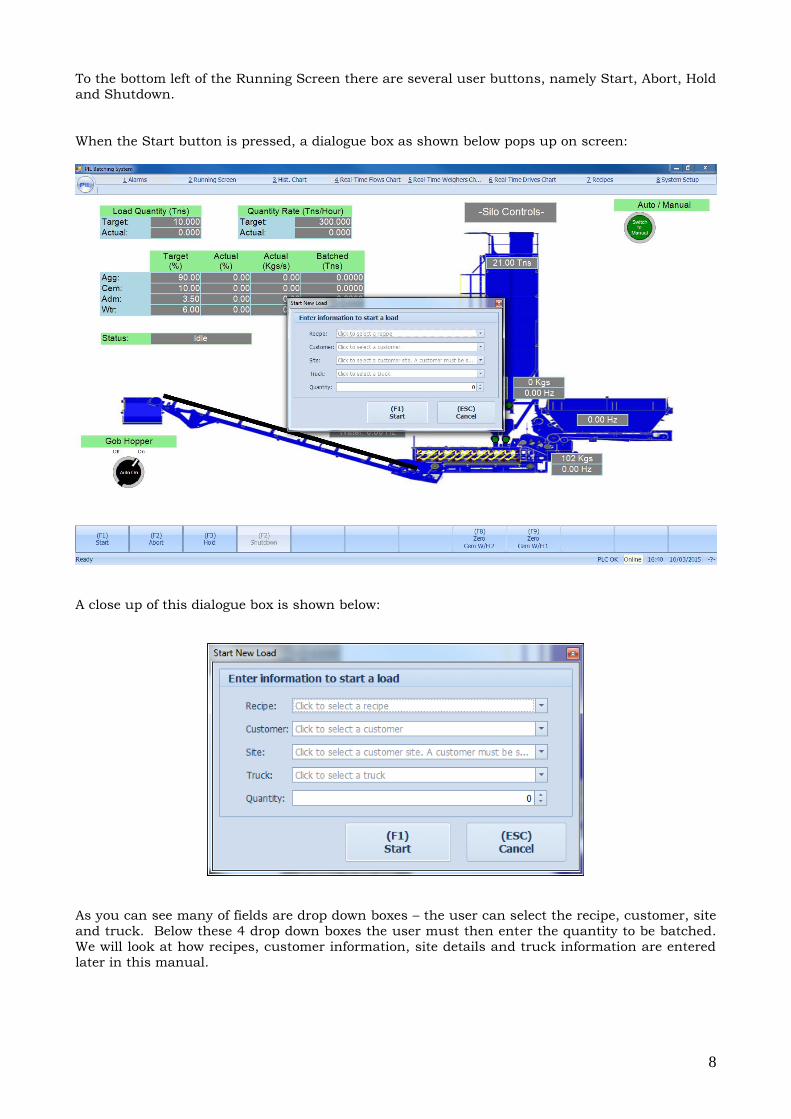
To the bottom left of the Running Screen there are several user buttons, namely Start, Abort, Hold
and Shutdown.
When the Start button is pressed, a dialogue box as shown below pops up on screen:
A close up of this dialogue box is shown below:
As you can see many of fields are drop down boxes – the user can select the recipe, customer, site
and truck. Below these 4 drop down boxes the user must then enter the quantity to be batched.
We will look at how recipes, customer information, site details and truck information are entered
later in this manual.
9
The second button along the bottom of the screen is the Abort button. When this button is pressed, the system immediately stops what it is doing and resets its automatic program – any
material already weighed up will have to be discharged from the system manually by the operator.
This buttons function is primarily used to reset the program, but in case of emergency if the
wrong mix has been setup or started, this button can be used to minimise the amount of material
produced in error.
Beside Abort is the Hold button, this button does exactly what it says, when this button is pressed the entire plant will pause what it is doing and wait until taken off hold. The mixer and
outloading conveyor will continue to run, but the aggregate belts feeding the mixer and also the
cement filling/emptying process will pause.
The last button in this row is the Shutdown button, this button is used to shutdown the plant
when in the middle of a production run. For example, if the user has started the plant off making 25 tons of material, the shutdown button can be pressed at anytime, this will ensure the plant
stops producing any further material and shuts the system down in an orderly fashion as it would
do if it had reached its 25 ton target, ensuring the aggregate weigh belt, incline belt and mixer are
totally drained out and empty of material.
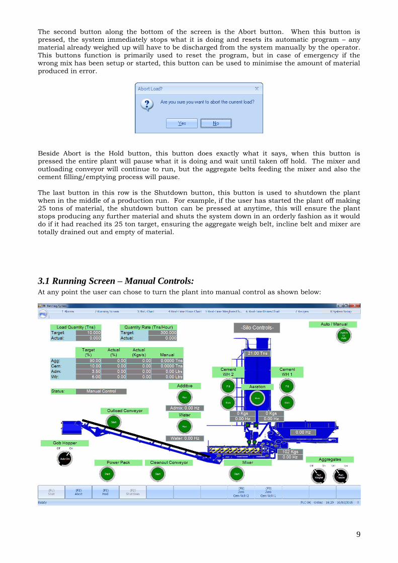
3.1 Running Screen – Manual Controls: At any point the user can chose to turn the plant into manual control as shown below:
10
When in manual mode, as you can see from the screenshot above, manual control buttons appear beside every device that can be controlled. These manual controls are very user friendly and very
intuitive. Each belt can be started and stopped, there are pushbuttons to fill and run the cement
weigh hoppers – after a few minutes use it will be extremely obvious how the manual controls
function.
The Gob Hopper has its own unique auto/manual control sequence. In the bottom left of the mimic screen, there is a Gob Hopper Auto On. When this button is turned onto the ‘On’ position,
the gob hopper door will operate as per the times configued in the plant setup (where there are
gob hopper open and gob hopper closed times). At the end of an automatic batch, the gob hopper
doors will always remain left open. When the Gob Hopper auto/manual selector switch is turned
to manual, 2 new push buttons will appear, one for open gob hopper, one for close gob hopper –
these buttons allow the operator to control the gob hopper door compeltely manually.
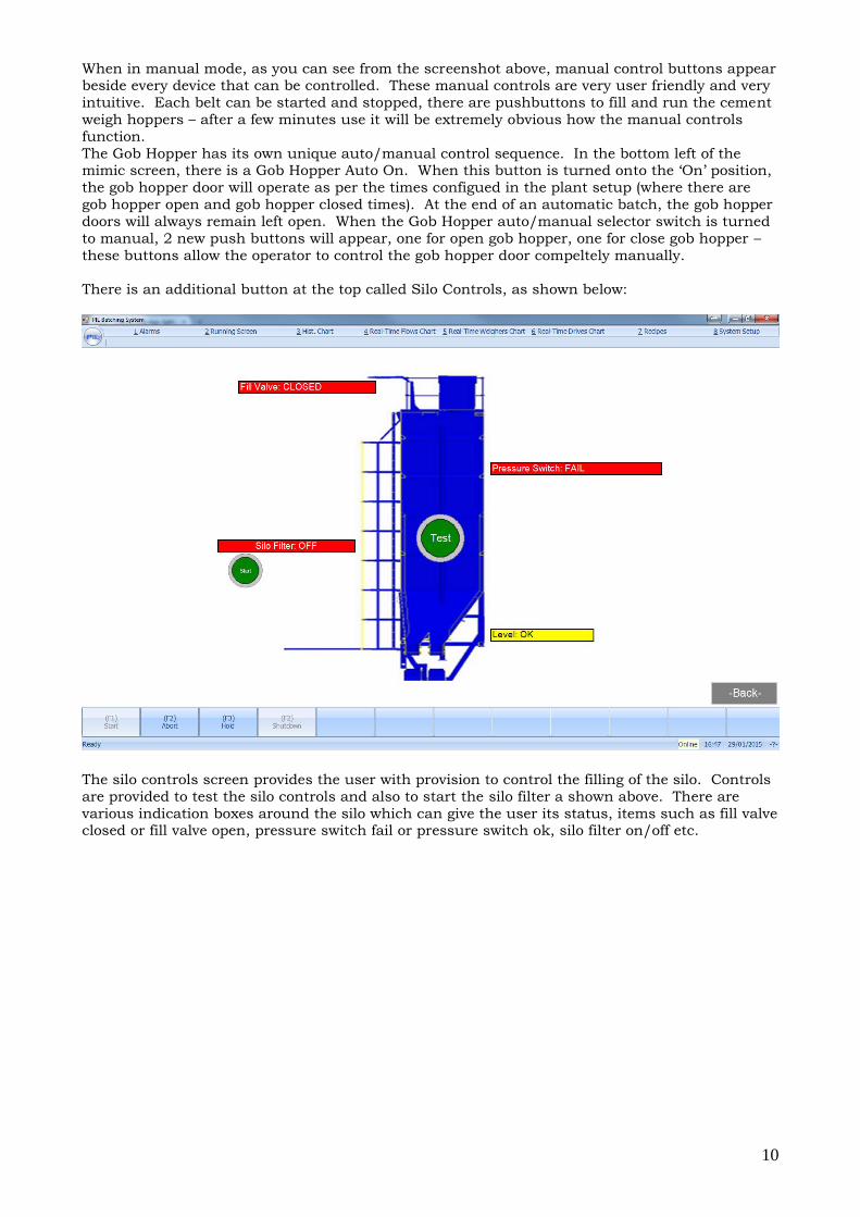
There is an additional button at the top called Silo Controls, as shown below:
The silo controls screen provides the user with provision to control the filling of the silo. Controls
are provided to test the silo controls and also to start the silo filter a shown above. There are
various indication boxes around the silo which can give the user its status, items such as fill valve closed or fill valve open, pressure switch fail or pressure switch ok, silo filter on/off etc.
11
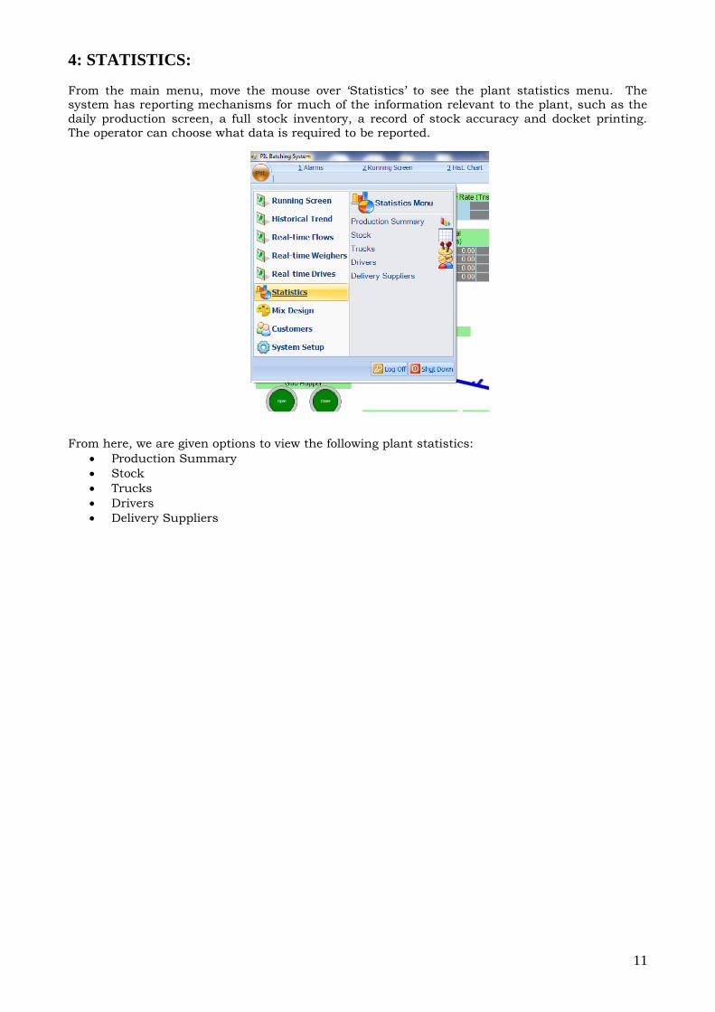
4: STATISTICS:
From the main menu, move the mouse over ‘Statistics’ to see the plant statistics menu. The system has reporting mechanisms for much of the information relevant to the plant, such as the
daily production screen, a full stock inventory, a record of stock accuracy and docket printing.
The operator can choose what data is required to be reported.
From here, we are given options to view the following plant statistics:
Production Summary
Stock
Trucks
Drivers
Delivery Suppliers
12
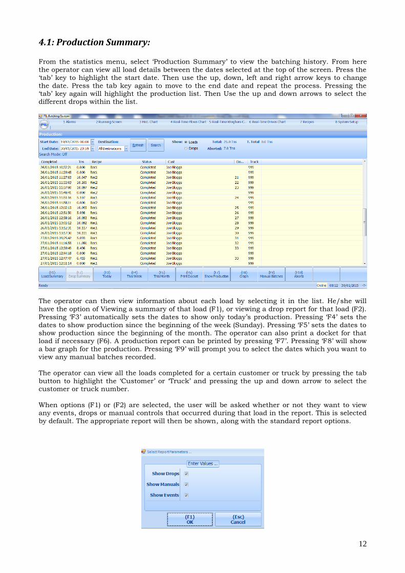
4.1: Production Summary:
From the statistics menu, select ‘Production Summary’ to view the batching history. From here
the operator can view all load details between the dates selected at the top of the screen. Press the
‘tab’ key to highlight the start date. Then use the up, down, left and right arrow keys to change
the date. Press the tab key again to move to the end date and repeat the process. Pressing the ‘tab’ key again will highlight the production list. Then Use the up and down arrows to select the
different drops within the list.
The operator can then view information about each load by selecting it in the list. He/she will
have the option of Viewing a summary of that load (F1), or viewing a drop report for that load (F2).
Pressing ‘F3’ automatically sets the dates to show only today’s production. Pressing ‘F4’ sets the
dates to show production since the beginning of the week (Sunday). Pressing ‘F5’ sets the dates to
show production since the beginning of the month. The operator can also print a docket for that load if necessary (F6). A production report can be printed by pressing ‘F7’. Pressing ‘F8’ will show
a bar graph for the production. Pressing ‘F9’ will prompt you to select the dates which you want to
view any manual batches recorded.
The operator can view all the loads completed for a certain customer or truck by pressing the tab
button to highlight the ‘Customer’ or ‘Truck’ and pressing the up and down arrow to select the customer or truck number.
When options (F1) or (F2) are selected, the user will be asked whether or not they want to view
any events, drops or manual controls that occurred during that load in the report. This is selected
by default. The appropriate report will then be shown, along with the standard report options.
13
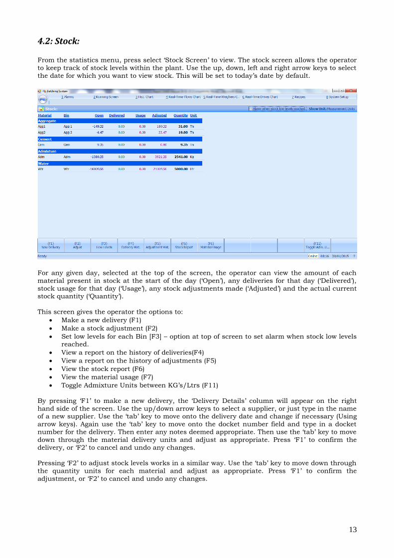
4.2: Stock:
From the statistics menu, press select ‘Stock Screen’ to view. The stock screen allows the operator
to keep track of stock levels within the plant. Use the up, down, left and right arrow keys to select
the date for which you want to view stock. This will be set to today’s date by default.
For any given day, selected at the top of the screen, the operator can view the amount of each
material present in stock at the start of the day (‘Open’), any deliveries for that day (‘Delivered’),
stock usage for that day (‘Usage’), any stock adjustments made (‘Adjusted’) and the actual current stock quantity (‘Quantity’).
This screen gives the operator the options to:
Make a new delivery (F1)
Make a stock adjustment (F2)
Set low levels for each Bin [F3] – option at top of screen to set alarm when stock low levels reached.
View a report on the history of deliveries(F4)
View a report on the history of adjustments (F5)
View the stock report (F6)
View the material usage (F7)
Toggle Admixture Units between KG’s/Ltrs (F11)
By pressing ‘F1’ to make a new delivery, the ‘Delivery Details’ column will appear on the right
hand side of the screen. Use the up/down arrow keys to select a supplier, or just type in the name of a new supplier. Use the ‘tab’ key to move onto the delivery date and change if necessary (Using
arrow keys). Again use the ‘tab’ key to move onto the docket number field and type in a docket
number for the delivery. Then enter any notes deemed appropriate. Then use the ‘tab’ key to move
down through the material delivery units and adjust as appropriate. Press ‘F1’ to confirm the
delivery, or ‘F2’ to cancel and undo any changes.
Pressing ‘F2’ to adjust stock levels works in a similar way. Use the ‘tab’ key to move down through
the quantity units for each material and adjust as appropriate. Press ‘F1’ to confirm the
adjustment, or ‘F2’ to cancel and undo any changes.
14
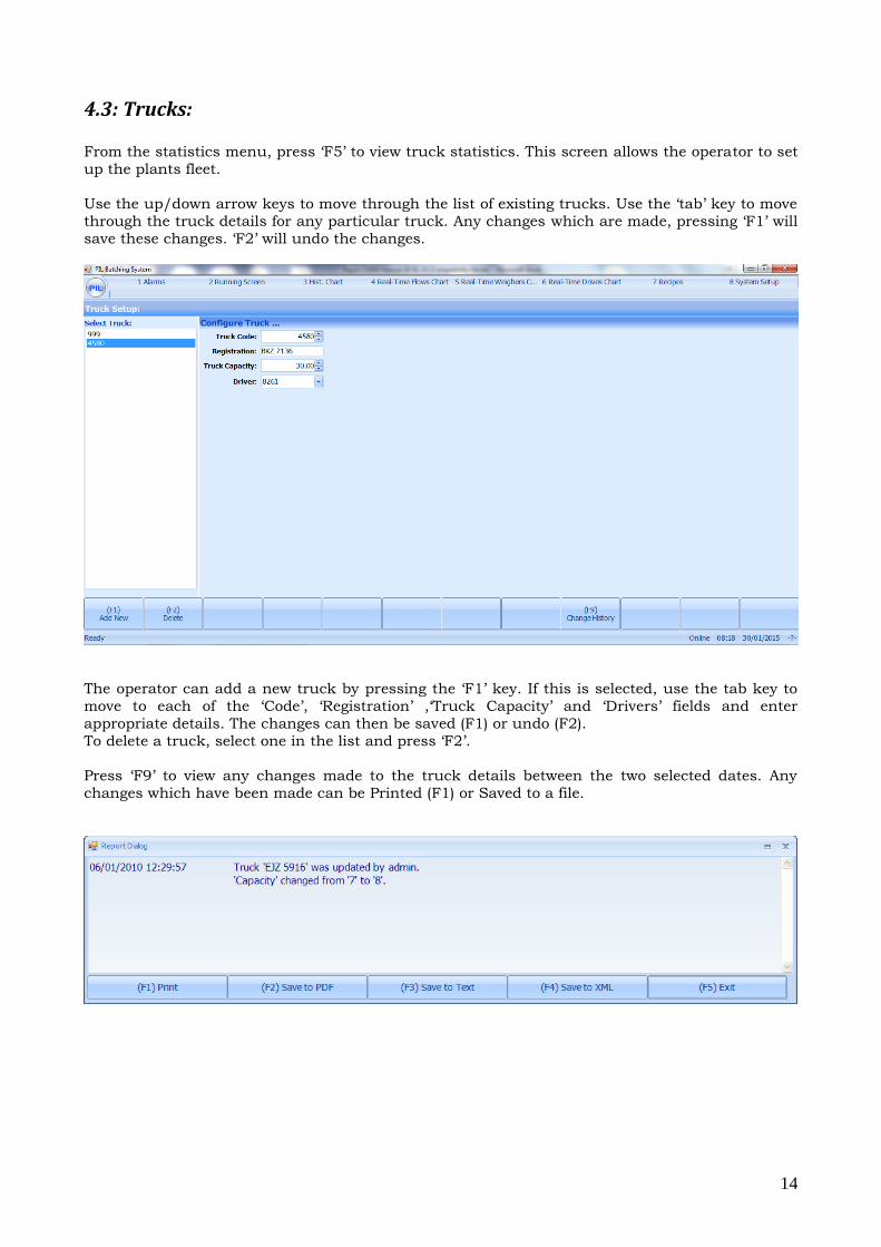
4.3: Trucks:
From the statistics menu, press ‘F5’ to view truck statistics. This screen allows the operator to set
up the plants fleet.
Use the up/down arrow keys to move through the list of existing trucks. Use the ‘tab’ key to move
through the truck details for any particular truck. Any changes which are made, pressing ‘F1’ will
save these changes. ‘F2’ will undo the changes.
The operator can add a new truck by pressing the ‘F1’ key. If this is selected, use the tab key to
move to each of the ‘Code’, ‘Registration’ ,‘Truck Capacity’ and ‘Drivers’ fields and enter
appropriate details. The changes can then be saved (F1) or undo (F2).
To delete a truck, select one in the list and press ‘F2’.
Press ‘F9’ to view any changes made to the truck details between the two selected dates. Any
changes which have been made can be Printed (F1) or Saved to a file.
15
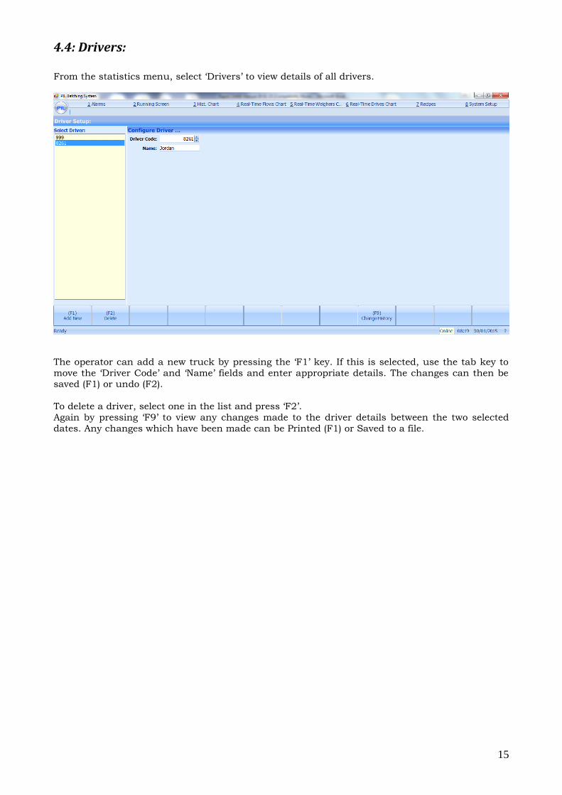
4.4: Drivers: From the statistics menu, select ‘Drivers’ to view details of all drivers.
The operator can add a new truck by pressing the ‘F1’ key. If this is selected, use the tab key to
move the ‘Driver Code’ and ‘Name’ fields and enter appropriate details. The changes can then be saved (F1) or undo (F2).
To delete a driver, select one in the list and press ‘F2’.
Again by pressing ‘F9’ to view any changes made to the driver details between the two selected
dates. Any changes which have been made can be Printed (F1) or Saved to a file.
16
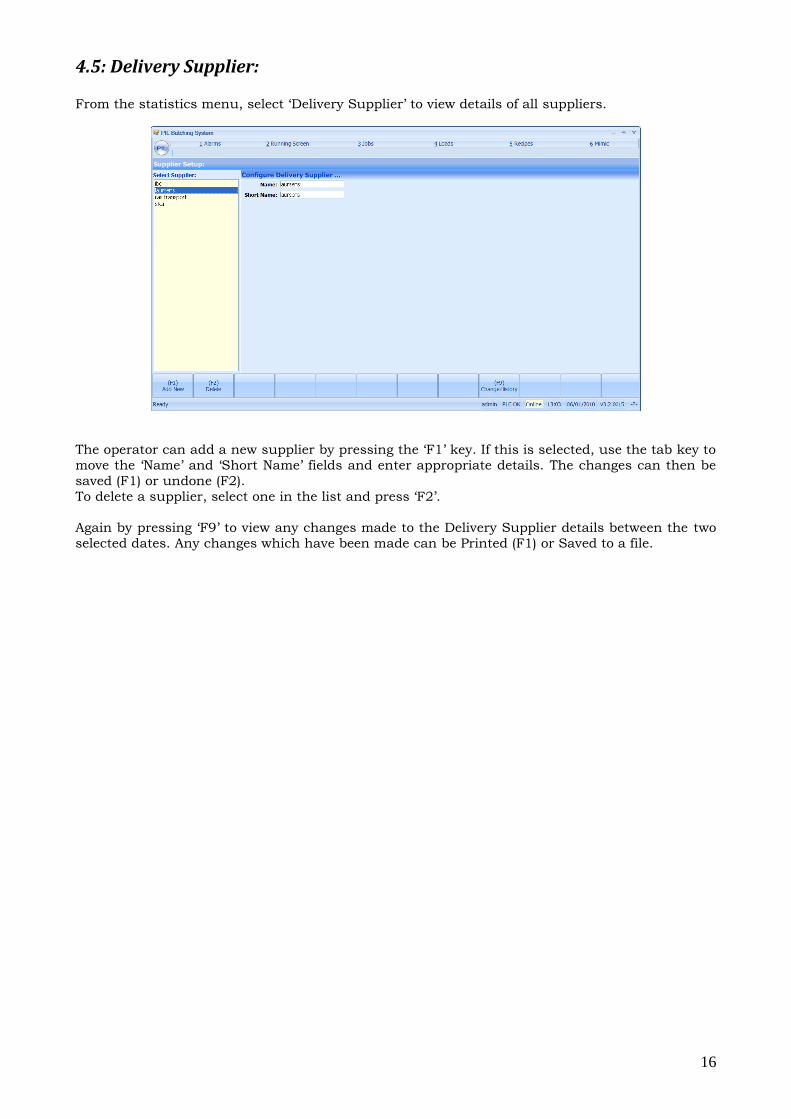
4.5: Delivery Supplier:
From the statistics menu, select ‘Delivery Supplier’ to view details of all suppliers.
The operator can add a new supplier by pressing the ‘F1’ key. If this is selected, use the tab key to
move the ‘Name’ and ‘Short Name’ fields and enter appropriate details. The changes can then be
saved (F1) or undone (F2).
To delete a supplier, select one in the list and press ‘F2’.
Again by pressing ‘F9’ to view any changes made to the Delivery Supplier details between the two
selected dates. Any changes which have been made can be Printed (F1) or Saved to a file.
17
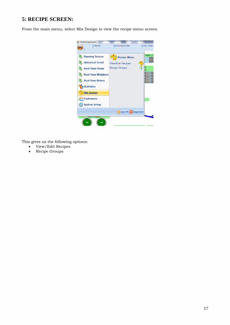
5: RECIPE SCREEN:
From the main menu, select Mix Design to view the recipe menu screen.
This gives us the following options:
View/Edit Recipes
Recipe Groups
18
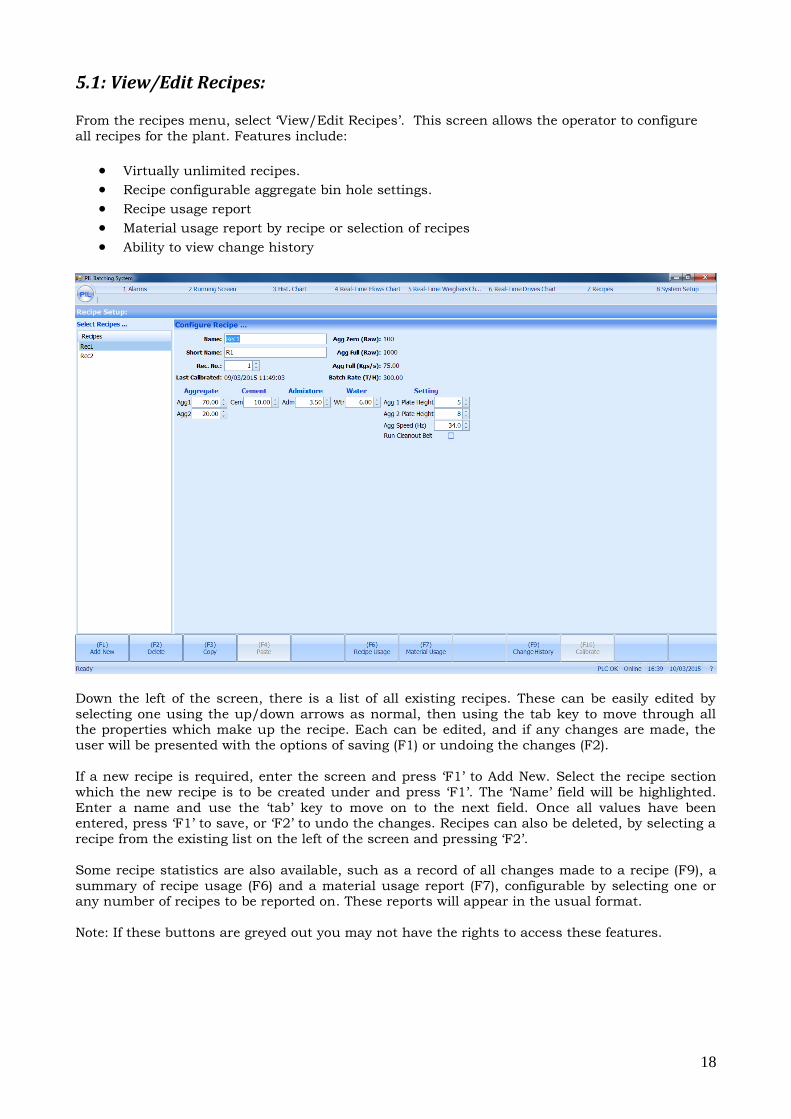
5.1: View/Edit Recipes:
From the recipes menu, select ‘View/Edit Recipes’. This screen allows the operator to configure
all recipes for the plant. Features include:
Virtually unlimited recipes.
Recipe configurable aggregate bin hole settings.
Recipe usage report
Material usage report by recipe or selection of recipes
Ability to view change history
Down the left of the screen, there is a list of all existing recipes. These can be easily edited by
selecting one using the up/down arrows as normal, then using the tab key to move through all the properties which make up the recipe. Each can be edited, and if any changes are made, the
user will be presented with the options of saving (F1) or undoing the changes (F2).
If a new recipe is required, enter the screen and press ‘F1’ to Add New. Select the recipe section
which the new recipe is to be created under and press ‘F1’. The ‘Name’ field will be highlighted.
Enter a name and use the ‘tab’ key to move on to the next field. Once all values have been entered, press ‘F1’ to save, or ‘F2’ to undo the changes. Recipes can also be deleted, by selecting a
recipe from the existing list on the left of the screen and pressing ‘F2’.
Some recipe statistics are also available, such as a record of all changes made to a recipe (F9), a
summary of recipe usage (F6) and a material usage report (F7), configurable by selecting one or any number of recipes to be reported on. These reports will appear in the usual format.
Note: If these buttons are greyed out you may not have the rights to access these features.
19
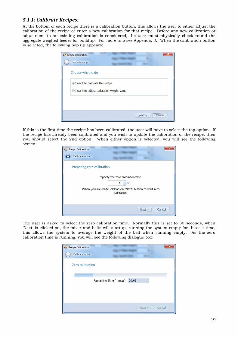
5.1.1: Calibrate Recipes: At the bottom of each recipe there is a calibration button, this allows the user to either adjust the calibration of the recipe or enter a new calibration for that recipe. Before any new calibration or
adjustment to an existing calibration is considered, the user must physically check round the
aggregate weighed feeder for buildup. For more info see Appendix 3. When the calibration button
is selected, the following pop up appears:
If this is the first time the recipe has been calibrated, the user will have to select the top option. If the recipe has already been calibrated and you wish to update the calibration of the recipe, then
you should select the 2nd option. When either option is selected, you will see the following
screen:
The user is asked to select the zero calibration time. Normally this is set to 30 seconds, when ‘Next’ is clicked on, the mixer and belts will startup, running the system empty for this set time,
this allows the system to average the weight of the belt when running empty. As the zero
calibration time is running, you will see the following dialogue box:
20
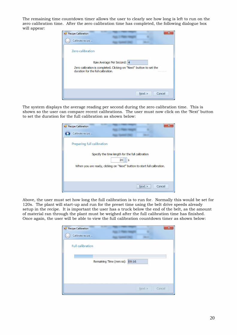
The remaining time countdown timer allows the user to clearly see how long is left to run on the zero calibration time. After the zero calibration time has completed, the following dialogue box
will appear:
The system displays the average reading per second during the zero calibration time. This is
shown so the user can compare recent calibrations. The user must now click on the ‘Next’ button to set the duration for the full calibration as shown below:
Above, the user must set how long the full calibration is to run for. Normally this would be set for
120s. The plant will start-up and run for the preset time using the belt drive speeds already setup in the recipe. It is important the user has a truck below the end of the belt, as the amount
of material ran through the plant must be weighed after the full calibration time has finished.
Once again, the user will be able to view the full calibration countdown timer as shown below:
21
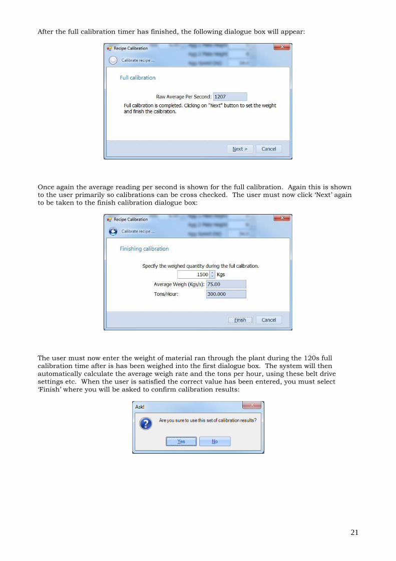
After the full calibration timer has finished, the following dialogue box will appear:
Once again the average reading per second is shown for the full calibration. Again this is shown to the user primarily so calibrations can be cross checked. The user must now click ‘Next’ again
to be taken to the finish calibration dialogue box:
The user must now enter the weight of material ran through the plant during the 120s full
calibration time after is has been weighed into the first dialogue box. The system will then
automatically calculate the average weigh rate and the tons per hour, using these belt drive
settings etc. When the user is satisfied the correct value has been entered, you must select
‘Finish’ where you will be asked to confirm calibration results:
22
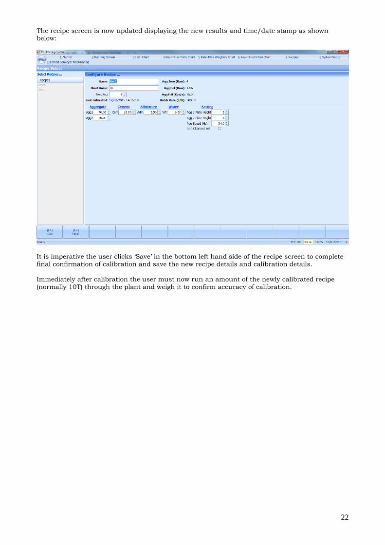
The recipe screen is now updated displaying the new results and time/date stamp as shown below:
It is imperative the user clicks ‘Save’ in the bottom left hand side of the recipe screen to complete
final confirmation of calibration and save the new recipe details and calibration details.
Immediately after calibration the user must now run an amount of the newly calibrated recipe
(normally 10T) through the plant and weigh it to confirm accuracy of calibration.
23
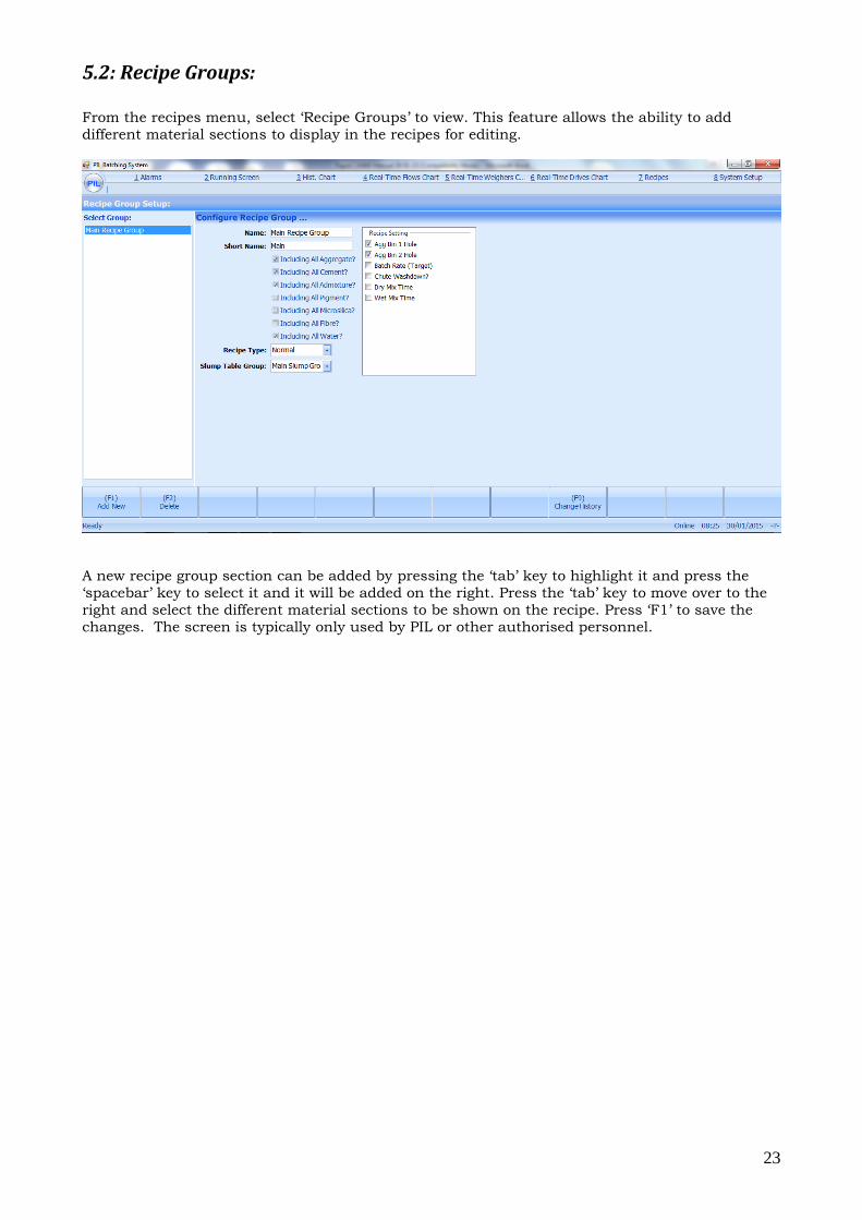
5.2: Recipe Groups: From the recipes menu, select ‘Recipe Groups’ to view. This feature allows the ability to add
different material sections to display in the recipes for editing.
A new recipe group section can be added by pressing the ‘tab’ key to highlight it and press the
‘spacebar’ key to select it and it will be added on the right. Press the ‘tab’ key to move over to the
right and select the different material sections to be shown on the recipe. Press ‘F1’ to save the
changes. The screen is typically only used by PIL or other authorised personnel.
24
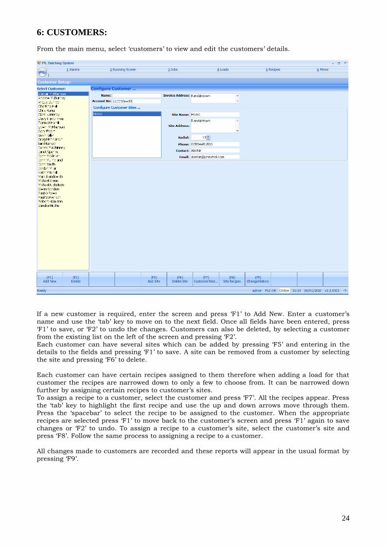
6: CUSTOMERS:
From the main menu, select ‘customers’ to view and edit the customers’ details.
If a new customer is required, enter the screen and press ‘F1’ to Add New. Enter a customer’s
name and use the ‘tab’ key to move on to the next field. Once all fields have been entered, press
‘F1’ to save, or ‘F2’ to undo the changes. Customers can also be deleted, by selecting a customer
from the existing list on the left of the screen and pressing ‘F2’.
Each customer can have several sites which can be added by pressing ‘F5’ and entering in the details to the fields and pressing ‘F1’ to save. A site can be removed from a customer by selecting
the site and pressing ‘F6’ to delete.
Each customer can have certain recipes assigned to them therefore when adding a load for that
customer the recipes are narrowed down to only a few to choose from. It can be narrowed down
further by assigning certain recipes to customer’s sites. To assign a recipe to a customer, select the customer and press ‘F7’. All the recipes appear. Press
the ‘tab’ key to highlight the first recipe and use the up and down arrows move through them.
Press the ‘spacebar’ to select the recipe to be assigned to the customer. When the appropriate
recipes are selected press ‘F1’ to move back to the customer’s screen and press ‘F1’ again to save
changes or ‘F2’ to undo. To assign a recipe to a customer’s site, select the customer’s site and press ‘F8’. Follow the same process to assigning a recipe to a customer.
All changes made to customers are recorded and these reports will appear in the usual format by
pressing ‘F9’.
25
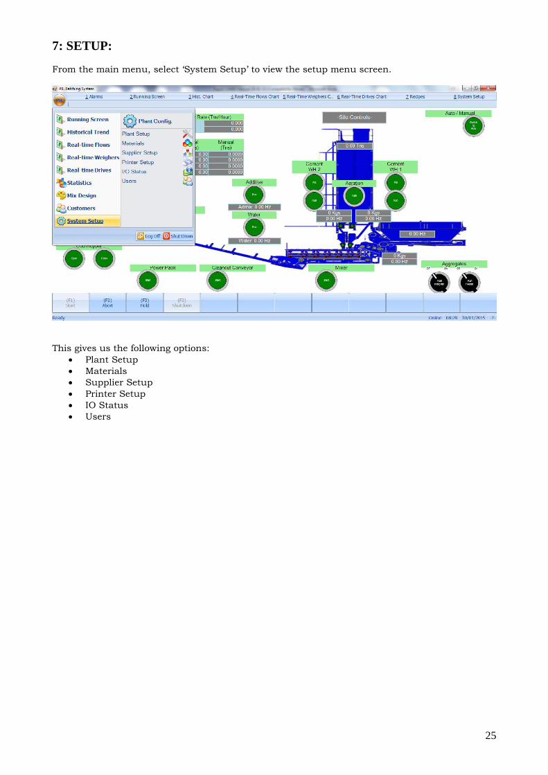
7: SETUP:
From the main menu, select ‘System Setup’ to view the setup menu screen.
This gives us the following options:
Plant Setup
Materials
Supplier Setup
Printer Setup
IO Status
Users
26
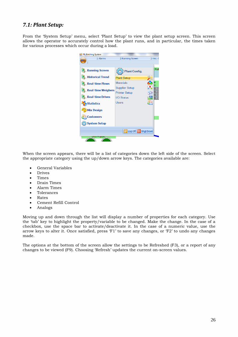
7.1: Plant Setup:
From the ‘System Setup’ menu, select ‘Plant Setup’ to view the plant setup screen. This screen
allows the operator to accurately control how the plant runs, and in particular, the times taken
for various processes which occur during a load.
When the screen appears, there will be a list of categories down the left side of the screen. Select
the appropriate category using the up/down arrow keys. The categories available are:
General Variables
Drives
Times
Drain Times
Alarm Times
Tolerances
Rates
Cement Refill Control
Analogs
Moving up and down through the list will display a number of properties for each category. Use
the ‘tab’ key to highlight the property/variable to be changed. Make the change. In the case of a
checkbox, use the space bar to activate/deactivate it. In the case of a numeric value, use the
arrow keys to alter it. Once satisfied, press ‘F1’ to save any changes, or ‘F2’ to undo any changes
made.
The options at the bottom of the screen allow the settings to be Refreshed (F3), or a report of any
changes to be viewed (F9). Choosing ‘Refresh’ updates the current on-screen values.
27
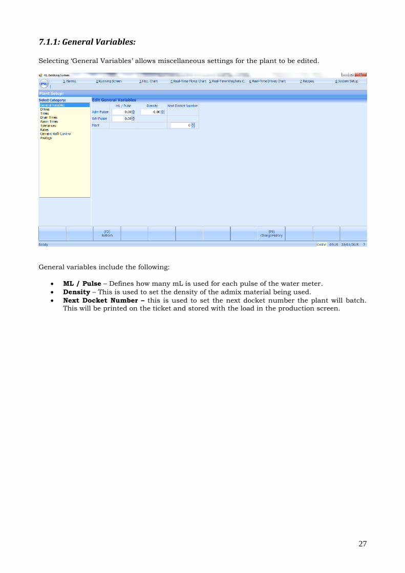
7.1.1: General Variables: Selecting ‘General Variables’ allows miscellaneous settings for the plant to be edited.
General variables include the following:
ML / Pulse – Defines how many mL is used for each pulse of the water meter.
Density – This is used to set the density of the admix material being used.
Next Docket Number – this is used to set the next docket number the plant will batch. This will be printed on the ticket and stored with the load in the production screen.
28
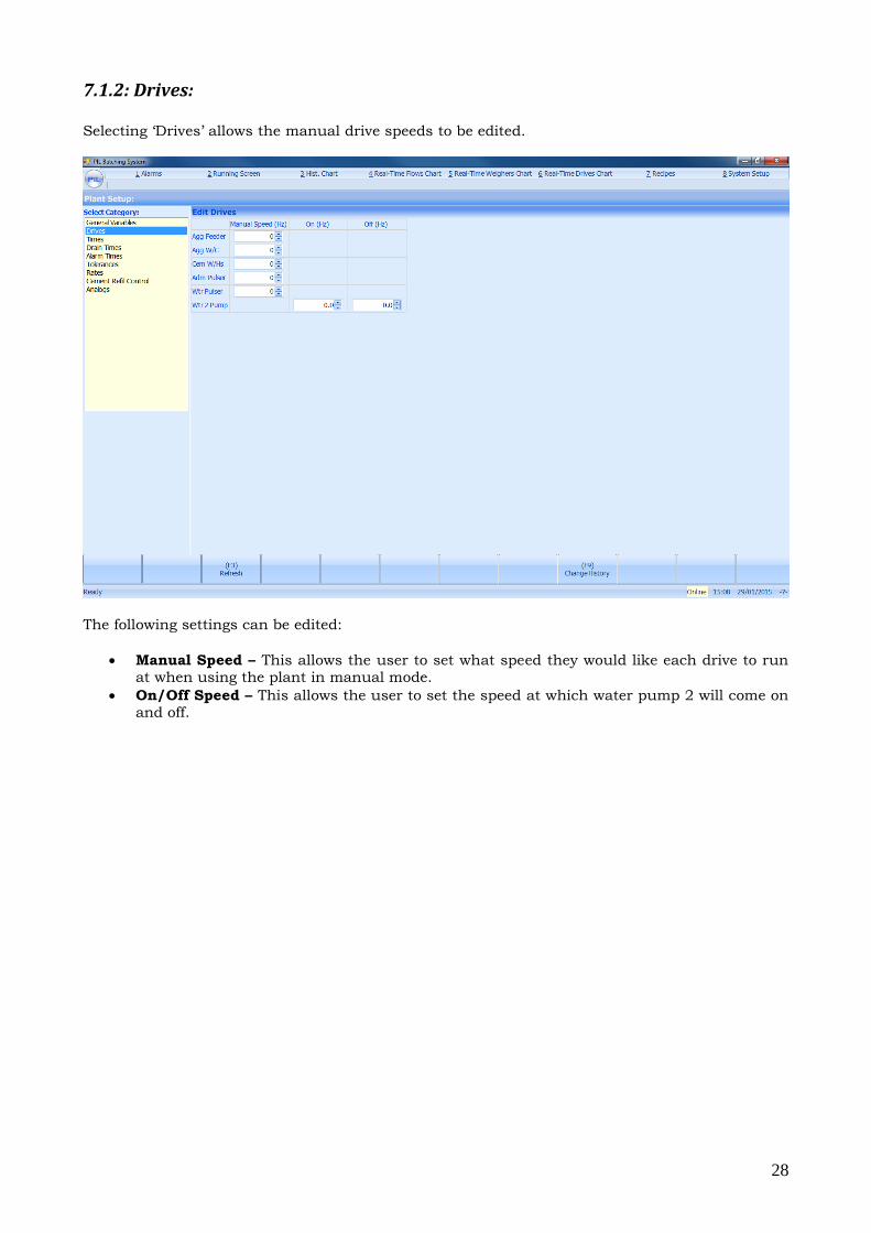
7.1.2: Drives: Selecting ‘Drives’ allows the manual drive speeds to be edited.
The following settings can be edited:
Manual Speed – This allows the user to set what speed they would like each drive to run at when using the plant in manual mode.
On/Off Speed – This allows the user to set the speed at which water pump 2 will come on and off.
29
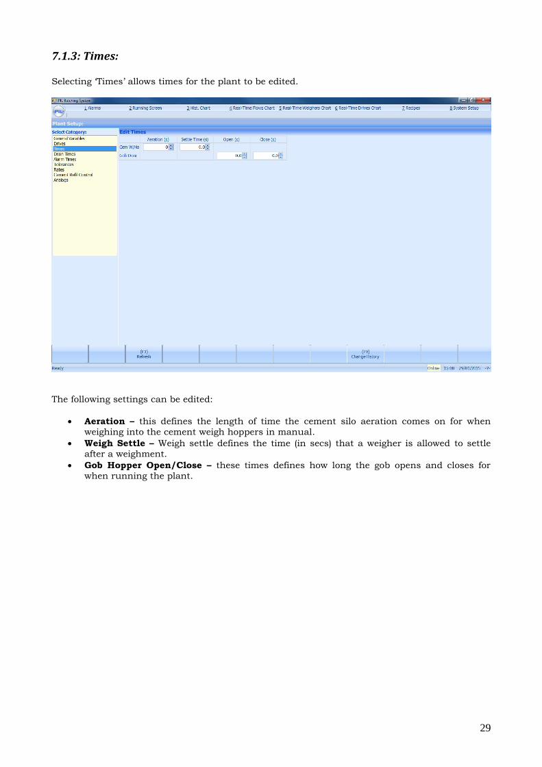
7.1.3: Times: Selecting ‘Times’ allows times for the plant to be edited.
The following settings can be edited:
Aeration – this defines the length of time the cement silo aeration comes on for when weighing into the cement weigh hoppers in manual.
Weigh Settle – Weigh settle defines the time (in secs) that a weigher is allowed to settle after a weighment.
Gob Hopper Open/Close – these times defines how long the gob opens and closes for when running the plant.
30
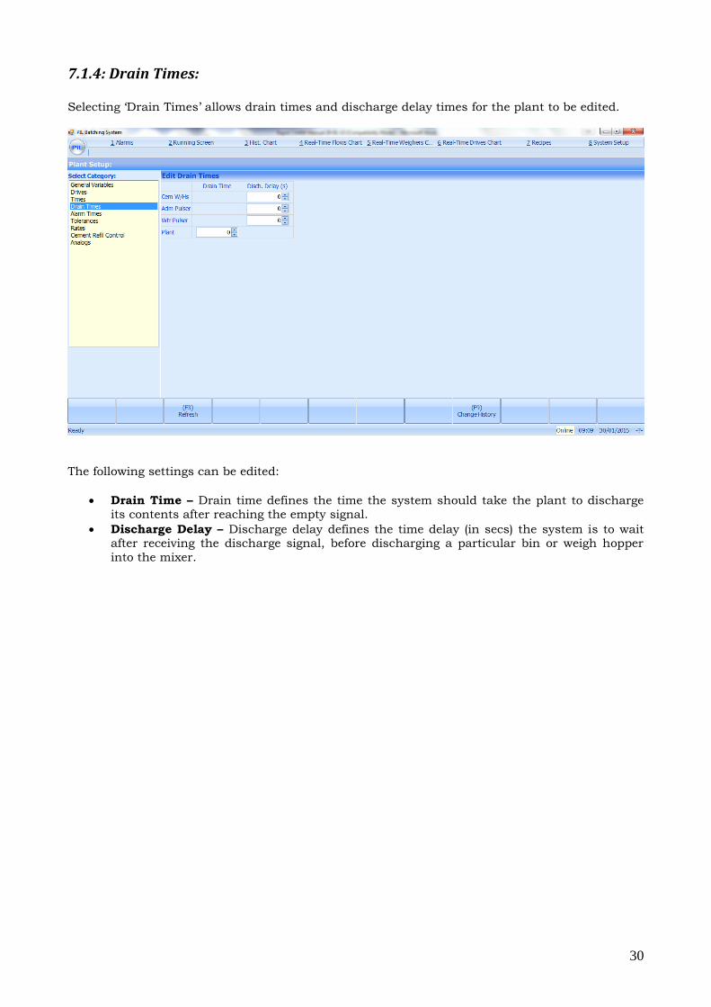
7.1.4: Drain Times: Selecting ‘Drain Times’ allows drain times and discharge delay times for the plant to be edited.
The following settings can be edited:
Drain Time – Drain time defines the time the system should take the plant to discharge its contents after reaching the empty signal.
Discharge Delay – Discharge delay defines the time delay (in secs) the system is to wait after receiving the discharge signal, before discharging a particular bin or weigh hopper
into the mixer.
31
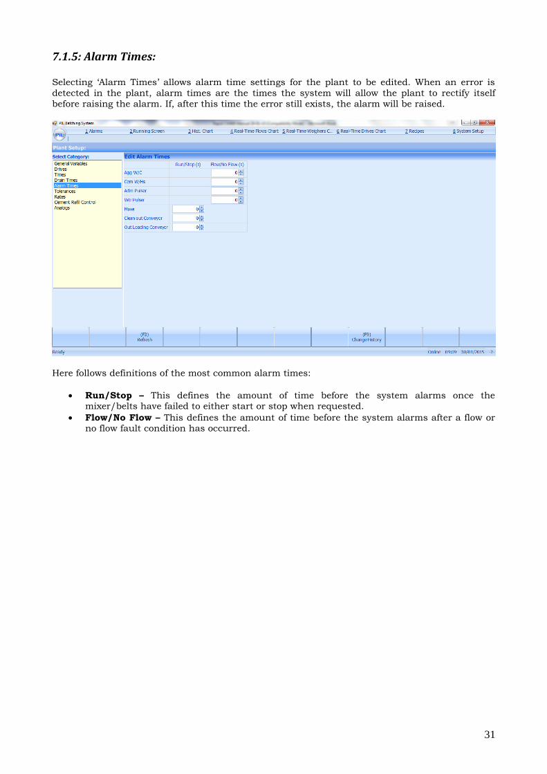
7.1.5: Alarm Times: Selecting ‘Alarm Times’ allows alarm time settings for the plant to be edited. When an error is
detected in the plant, alarm times are the times the system will allow the plant to rectify itself
before raising the alarm. If, after this time the error still exists, the alarm will be raised.
Here follows definitions of the most common alarm times:
Run/Stop – This defines the amount of time before the system alarms once the mixer/belts have failed to either start or stop when requested.
Flow/No Flow – This defines the amount of time before the system alarms after a flow or no flow fault condition has occurred.
32
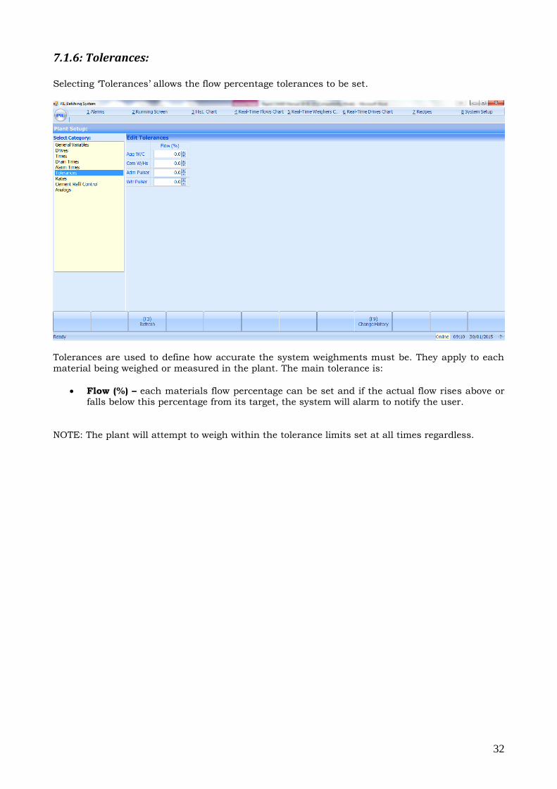
7.1.6: Tolerances: Selecting ‘Tolerances’ allows the flow percentage tolerances to be set.
Tolerances are used to define how accurate the system weighments must be. They apply to each
material being weighed or measured in the plant. The main tolerance is:
Flow (%) – each materials flow percentage can be set and if the actual flow rises above or falls below this percentage from its target, the system will alarm to notify the user.
NOTE: The plant will attempt to weigh within the tolerance limits set at all times regardless.
33
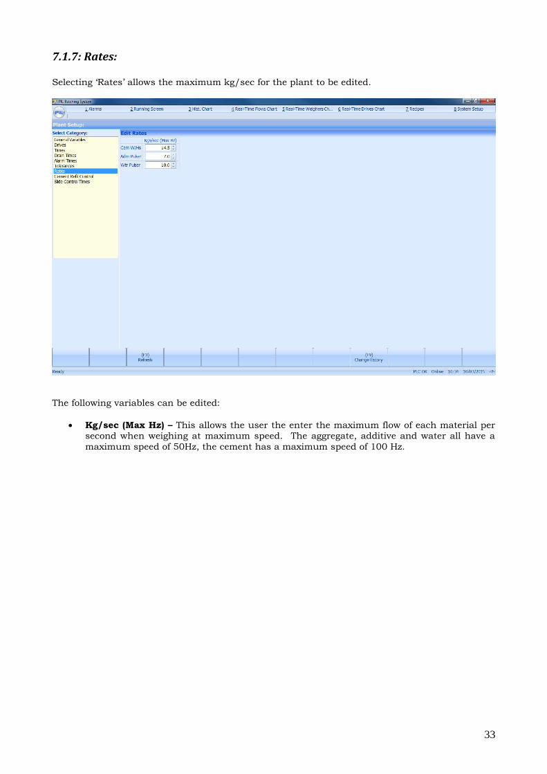
7.1.7: Rates: Selecting ‘Rates’ allows the maximum kg/sec for the plant to be edited.
The following variables can be edited:
Kg/sec (Max Hz) – This allows the user the enter the maximum flow of each material per second when weighing at maximum speed. The aggregate, additive and water all have a
maximum speed of 50Hz, the cement has a maximum speed of 100 Hz.
34
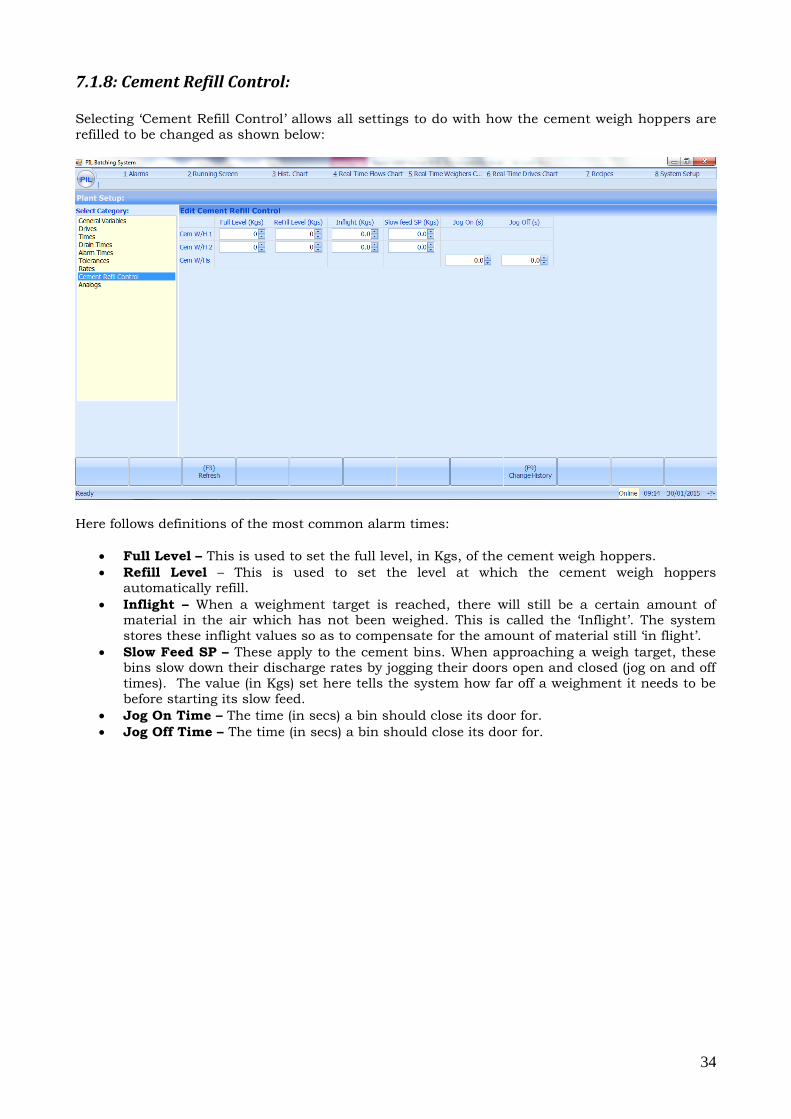
7.1.8: Cement Refill Control: Selecting ‘Cement Refill Control’ allows all settings to do with how the cement weigh hoppers are
refilled to be changed as shown below:
Here follows definitions of the most common alarm times:
Full Level – This is used to set the full level, in Kgs, of the cement weigh hoppers.
Refill Level – This is used to set the level at which the cement weigh hoppers automatically refill.
Inflight – When a weighment target is reached, there will still be a certain amount of material in the air which has not been weighed. This is called the ‘Inflight’. The system
stores these inflight values so as to compensate for the amount of material still ‘in flight’.
Slow Feed SP – These apply to the cement bins. When approaching a weigh target, these bins slow down their discharge rates by jogging their doors open and closed (jog on and off
times). The value (in Kgs) set here tells the system how far off a weighment it needs to be
before starting its slow feed.
Jog On Time – The time (in secs) a bin should close its door for.
Jog Off Time – The time (in secs) a bin should close its door for.
35
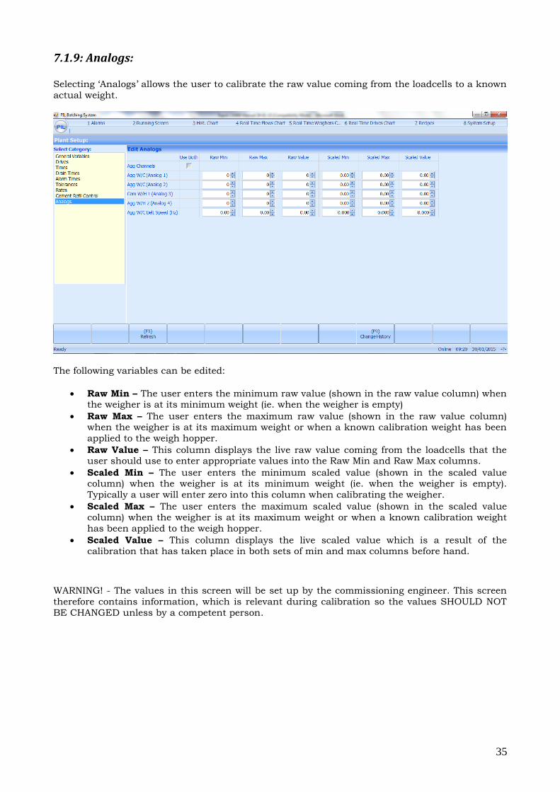
7.1.9: Analogs: Selecting ‘Analogs’ allows the user to calibrate the raw value coming from the loadcells to a known
actual weight.
The following variables can be edited:
Raw Min – The user enters the minimum raw value (shown in the raw value column) when the weigher is at its minimum weight (ie. when the weigher is empty)
Raw Max – The user enters the maximum raw value (shown in the raw value column) when the weigher is at its maximum weight or when a known calibration weight has been
applied to the weigh hopper.
Raw Value – This column displays the live raw value coming from the loadcells that the user should use to enter appropriate values into the Raw Min and Raw Max columns.
Scaled Min – The user enters the minimum scaled value (shown in the scaled value column) when the weigher is at its minimum weight (ie. when the weigher is empty).
Typically a user will enter zero into this column when calibrating the weigher.
Scaled Max – The user enters the maximum scaled value (shown in the scaled value column) when the weigher is at its maximum weight or when a known calibration weight
has been applied to the weigh hopper.
Scaled Value – This column displays the live scaled value which is a result of the calibration that has taken place in both sets of min and max columns before hand.
WARNING! - The values in this screen will be set up by the commissioning engineer. This screen
therefore contains information, which is relevant during calibration so the values SHOULD NOT
BE CHANGED unless by a competent person.
36
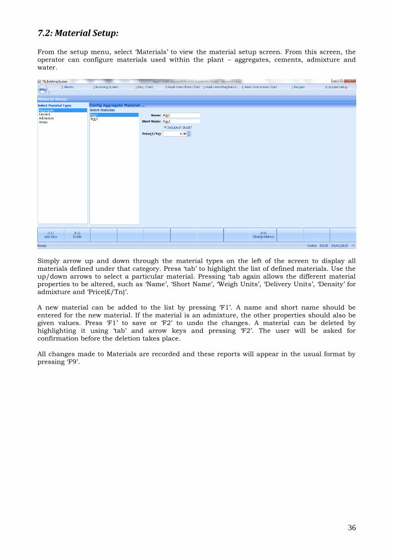
7.2: Material Setup:
From the setup menu, select ‘Materials’ to view the material setup screen. From this screen, the
operator can configure materials used within the plant – aggregates, cements, admixture and
water.
Simply arrow up and down through the material types on the left of the screen to display all
materials defined under that category. Press ‘tab’ to highlight the list of defined materials. Use the
up/down arrows to select a particular material. Pressing ‘tab again allows the different material properties to be altered, such as ‘Name’, ‘Short Name’, ‘Weigh Units’, ‘Delivery Units’, ‘Density’ for
admixture and ‘Price(£/Tn)’.
A new material can be added to the list by pressing ‘F1’. A name and short name should be
entered for the new material. If the material is an admixture, the other properties should also be given values. Press ‘F1’ to save or ‘F2’ to undo the changes. A material can be deleted by
highlighting it using ‘tab’ and arrow keys and pressing ‘F2’. The user will be asked for
confirmation before the deletion takes place.
All changes made to Materials are recorded and these reports will appear in the usual format by
pressing ‘F9’.
37
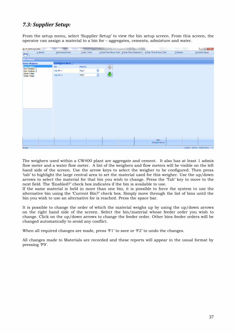
7.3: Supplier Setup:
From the setup menu, select ‘Supplier Setup’ to view the bin setup screen. From this screen, the
operator can assign a material to a bin for – aggregates, cements, admixture and water.
The weighers used within a CW400 plant are aggregate and cement. It also has at least 1 admix
flow meter and a water flow meter. A list of the weighers and flow meters will be visible on the left
hand side of the screen. Use the arrow keys to select the weigher to be configured. Then press
‘tab’ to highlight the large central area to set the material used for this weigher. Use the up/down
arrows to select the material for that bin you wish to change. Press the ‘Tab’ key to move to the
next field. The ‘Enabled?’ check box indicates if the bin is available to use. If the same material is held in more than one bin, it is possible to force the system to use the
alternative bin using the ‘Current Bin?’ check box. Simply move through the list of bins until the
bin you wish to use an alternative for is reached. Press the space bar.
It is possible to change the order of which the material weighs up by using the up/down arrows on the right hand side of the screen. Select the bin/material whose feeder order you wish to
change. Click on the up/down arrows to change the feeder order. Other bins feeder orders will be
changed automatically to avoid any conflict.
When all required changes are made, press ‘F1’ to save or ‘F2’ to undo the changes.
All changes made to Materials are recorded and these reports will appear in the usual format by
pressing ‘F9’.
38
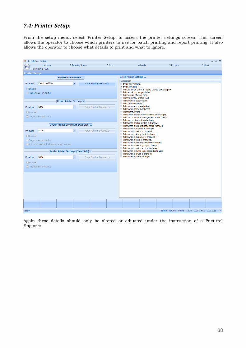
7.4: Printer Setup:
From the setup menu, select ‘Printer Setup’ to access the printer settings screen. This screen
allows the operator to choose which printers to use for batch printing and report printing. It also
allows the operator to choose what details to print and what to ignore.
Again these details should only be altered or adjusted under the instruction of a Pneutrol
Engineer.
39
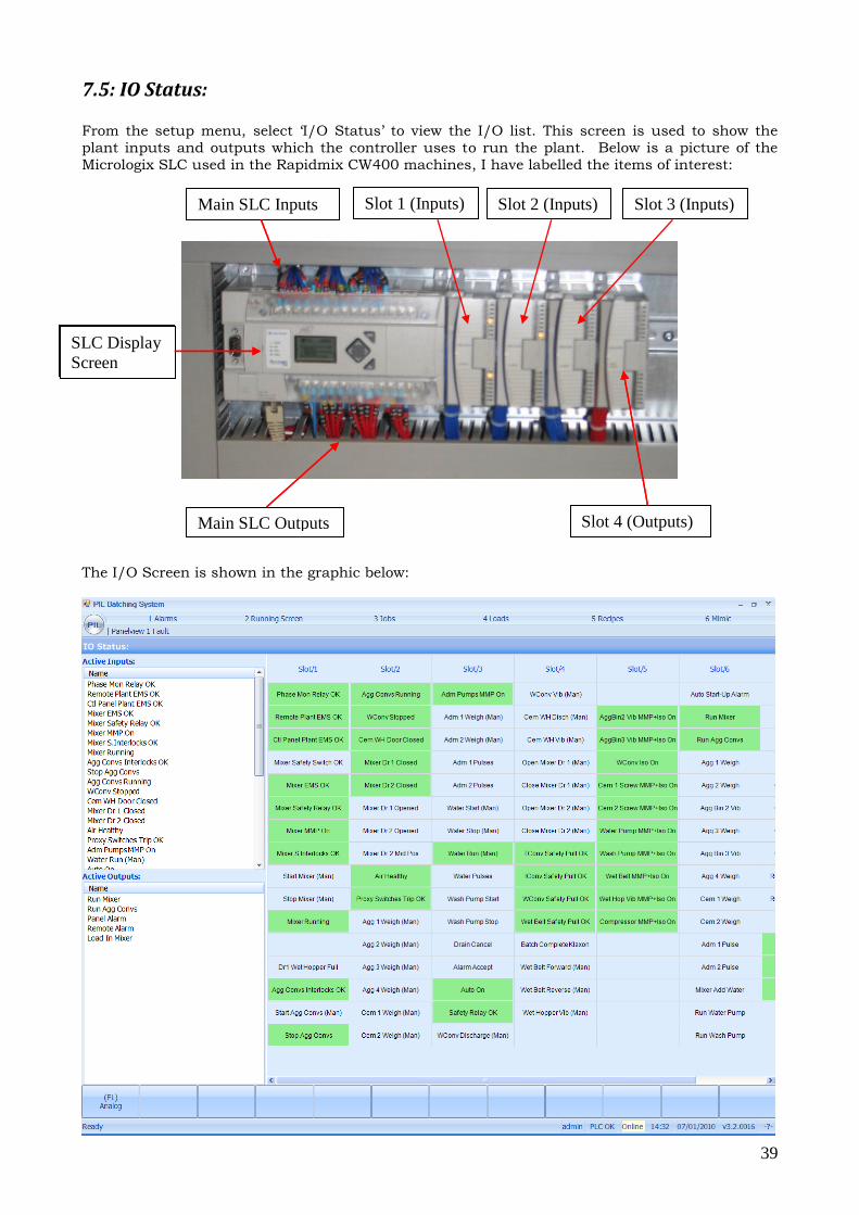
7.5: IO Status:
From the setup menu, select ‘I/O Status’ to view the I/O list. This screen is used to show the
plant inputs and outputs which the controller uses to run the plant. Below is a picture of the
Micrologix SLC used in the Rapidmix CW400 machines, I have labelled the items of interest:
The I/O Screen is shown in the graphic below:
Main SLC Inputs Slot 1 (Inputs) Slot 2 (Inputs) Slot 3 (Inputs)
Main SLC Outputs Slot 3 (Outputs)
SLC Display
Screen
Main SLC Outputs Slot 4 (Outputs)
SLC Display
Screen
40
The I/O screen and the information displayed thereon is useful for plant engineers should a fault
arise. Active inputs and outputs are highlighted green. Each input/output displays the name
complete with wire number, so fault finding can be conducted with as much ease as possible.
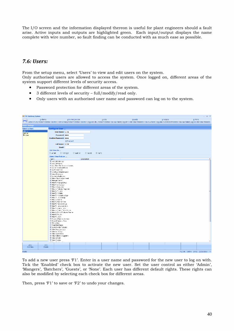
7.6: Users:
From the setup menu, select ‘Users’ to view and edit users on the system.
Only authorised users are allowed to access the system. Once logged on, different areas of the system support different levels of security access.
Password protection for different areas of the system.
3 different levels of security – full/modify/read only.
Only users with an authorised user name and password can log on to the system.
To add a new user press ‘F1’. Enter in a user name and password for the new user to log on with.
Tick the ‘Enabled’ check box to activate the new user. Set the user control as either ‘Admin’, ‘Mangers’, ‘Batchers’, ‘Guests’, or ‘None’. Each user has different default rights. These rights can
also be modified by selecting each check box for different areas.
Then, press ‘F1’ to save or ‘F2’ to undo your changes.
41
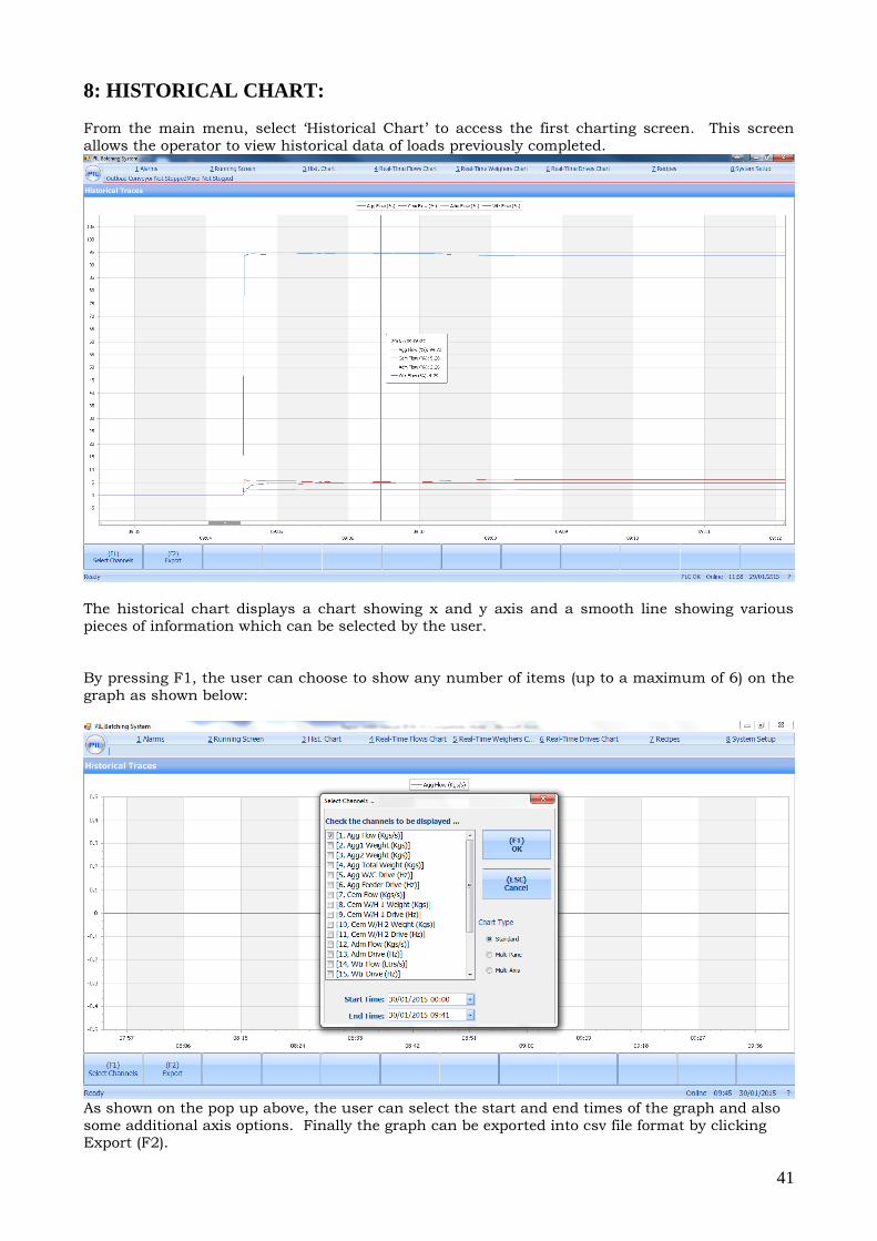
8: HISTORICAL CHART: From the main menu, select ‘Historical Chart’ to access the first charting screen. This screen
allows the operator to view historical data of loads previously completed.
The historical chart displays a chart showing x and y axis and a smooth line showing various
pieces of information which can be selected by the user.
By pressing F1, the user can choose to show any number of items (up to a maximum of 6) on the
graph as shown below:
As shown on the pop up above, the user can select the start and end times of the graph and also
some additional axis options. Finally the graph can be exported into csv file format by clicking Export (F2).
42
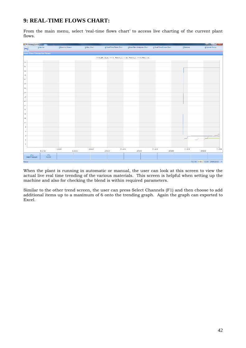
9: REAL-TIME FLOWS CHART:
From the main menu, select ‘real-time flows chart’ to access live charting of the current plant flows.
When the plant is running in automatic or manual, the user can look at this screen to view the
actual live real time trending of the various materials. This screen is helpful when setting up the
machine and also for checking the blend is within required parameters.
Similar to the other trend screen, the user can press Select Channels (F1) and then choose to add
additional items up to a maximum of 6 onto the trending graph. Again the graph can exported to
Excel.
43
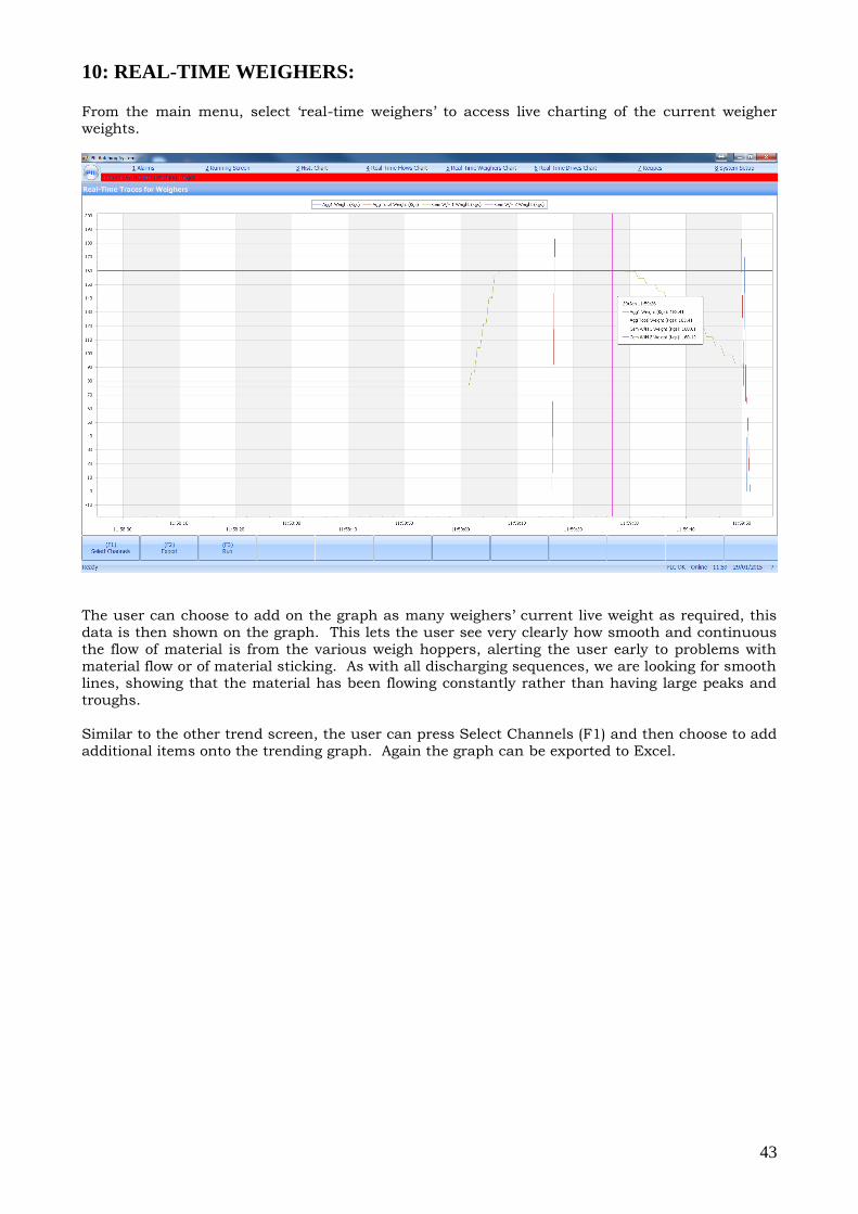
10: REAL-TIME WEIGHERS: From the main menu, select ‘real-time weighers’ to access live charting of the current weigher
weights.
The user can choose to add on the graph as many weighers’ current live weight as required, this
data is then shown on the graph. This lets the user see very clearly how smooth and continuous
the flow of material is from the various weigh hoppers, alerting the user early to problems with
material flow or of material sticking. As with all discharging sequences, we are looking for smooth lines, showing that the material has been flowing constantly rather than having large peaks and
troughs.
Similar to the other trend screen, the user can press Select Channels (F1) and then choose to add
additional items onto the trending graph. Again the graph can be exported to Excel.
44
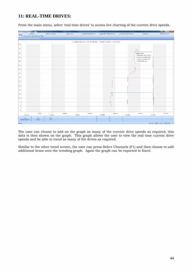
11: REAL-TIME DRIVES: From the main menu, select ‘real-time drives’ to access live charting of the current drive speeds.
The user can choose to add on the graph as many of the current drive speeds as required, this
data is then shown on the graph. This graph allows the user to view the real time current drive speeds and be able to trend as many of the drives as required.
Similar to the other trend screen, the user can press Select Channels (F1) and then choose to add
additional items onto the trending graph. Again the graph can be exported to Excel.
45
12: DIAGNOSTICS/ALARMS:
12.1: Alarms Screen:
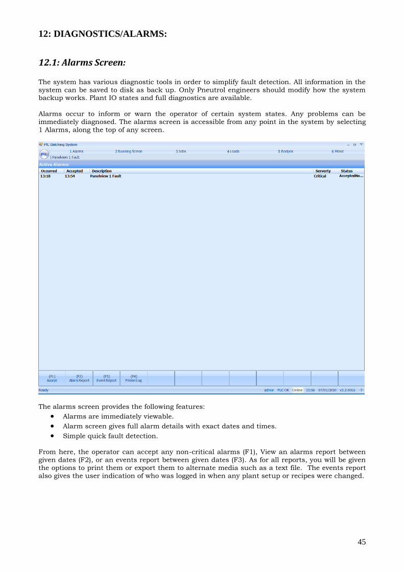
The system has various diagnostic tools in order to simplify fault detection. All information in the
system can be saved to disk as back up. Only Pneutrol engineers should modify how the system backup works. Plant IO states and full diagnostics are available.
Alarms occur to inform or warn the operator of certain system states. Any problems can be
immediately diagnosed. The alarms screen is accessible from any point in the system by selecting
1 Alarms, along the top of any screen.
The alarms screen provides the following features:
Alarms are immediately viewable.
Alarm screen gives full alarm details with exact dates and times.
Simple quick fault detection.
From here, the operator can accept any non-critical alarms (F1), View an alarms report between
given dates (F2), or an events report between given dates (F3). As for all reports, you will be given
the options to print them or export them to alternate media such as a text file. The events report
also gives the user indication of who was logged in when any plant setup or recipes were changed.
46
Dealing with Alarms:
An alarm is dealt with as follows:
From the HMI;
1. Press ‘1 Alarms’ to display the Alarm screen. This will show a list of all the active alarms. 2. If the alarm is an out of tolerance alarm or similar, check the screen to see which item was out
of tolerance and by how much. If it is not serious then the weight may be accepted by pressing
‘F1’. If there is a serious weight discrepancy then the system may need to be switched into
MANUAL and all existing materials put through the system until the system is clear. Investigate
the cause of the discrepancy and when the cause has been eradicated, abort the process and
restart the system in auto. 3. If you are confident that you know the cause of the alarm then pressing the 'F1' key on the
keyboard will accept the alarm.
PLEASE REVIEW APPENDIX 4 AT THE BACK OF THIS DOCUMENT FOR FULL ALARMS LIST
13: REMOTE ACCESS:
The customer must provide suitable 3G dongle or similar, allowing remote access for
management, PIL technical staff, your distributor or your agent:
Technicians can interrogate the system and assist in fault
finding/fixing from their headquarters
PIL Technicians can download new software updates
Management/accounts staff can view/receive production reports
from their own offices as required
System can be started from a remote interface
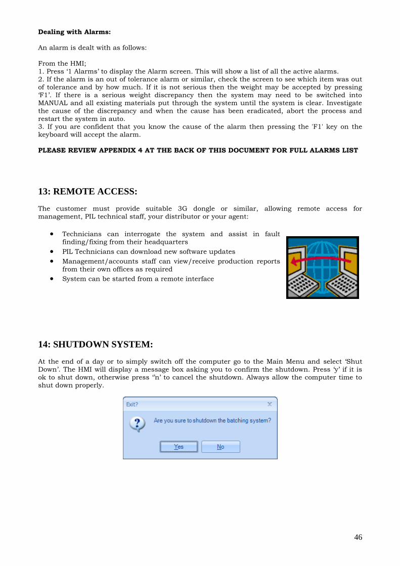
14: SHUTDOWN SYSTEM:
At the end of a day or to simply switch off the computer go to the Main Menu and select ‘Shut
Down’. The HMI will display a message box asking you to confirm the shutdown. Press ‘y’ if it is
ok to shut down, otherwise press ‘’n’ to cancel the shutdown. Always allow the computer time to
shut down properly.

47
15: USEFUL INFORMATION:
15.1: Pausing The System:
Should it be necessary to pause the system for any reason, choose the HOLD/RUN option on the
running screen. All screws, motors etc will be stopped and the plant will stay in its present state.
To resume again from the running screen choose the HOLD/RUN option again.
Note: Do NOT press the ABORT option as this will completely reset the Controller to the start
position and the load will be aborted. The system will then have to be completely cleared before
you can start any more batches.
Note: This in no way removes power from the equipment and should not be used to enable
someone to work at a piece of equipment. If work must be done then the system should be "Cleared", all the mix passed through the system in the normal way, placed in RESET and the
equipment then ELECTRICALLY ISOLATED, both on the CONTROL PANEL (Key Switch) and the
STARTER Panel (Mains Isolator).
15.2: Emergency Stop:
In the case where it is imperative that the system be shut down immediately, i.e. as in the case of
an accident then the "Red" EMERGENCY STOP button on the left hand side of the panel should
be pressed.
This will stop the plant batching operation i.e. stop belts, mixer, screws etc. Further isolation can
be carried out by turning the Isolator handle on the starter panel to the OFF position. Should this
facility be used, then it is necessary, on starting up again, to clear the system manually.
15.3: What To Do If You Have A Problem?
In the event of a system failure, immediately take a picture of the running screen on the HMI with
a camera phone of small camera. Also take a picture of the inputs/outputs using the facility
provided in the 'INPUT/OUTPUT' screen. Carry out a visual inspection of the plant and write down any faults and correct if possible.
If no faults are noted, clear the system completely in manual mode and attempt the next job or
batch in automatic mode. Observe plant functions and record data as necessary. Relay all
findings to PIL.
The more comprehensive the information supplied to Pneutrol, the easier it will be to provide a
solution to the fault. Also have available all plant control drawings to discuss with Pneutrol
Engineers.
Email: [email protected]
48
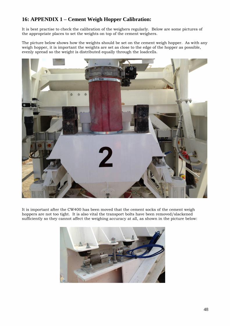
16: APPENDIX 1 – Cement Weigh Hopper Calibration:
It is best practise to check the calibration of the weighers regularly. Below are some pictures of the appropriate places to set the weights on top of the cement weighers.
The picture below shows how the weights should be set on the cement weigh hopper. As with any
weigh hopper, it is important the weights are set as close to the edge of the hopper as possible,
evenly spread so the weight is distributed equally through the loadcells.
It is important after the CW400 has been moved that the cement socks of the cement weigh
hoppers are not too tight. It is also vital the transport bolts have been removed/slackened sufficiently so they cannot affect the weighing accuracy at all, as shown in the picture below:
49
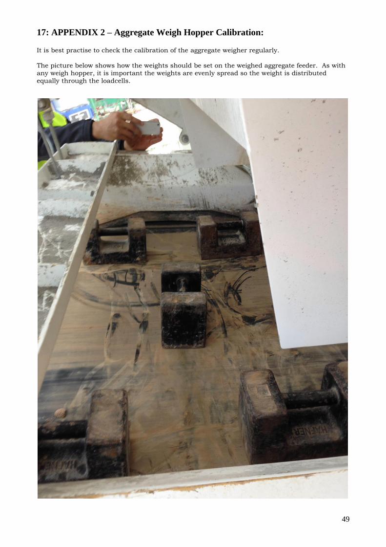
17: APPENDIX 2 – Aggregate Weigh Hopper Calibration: It is best practise to check the calibration of the aggregate weigher regularly.
The picture below shows how the weights should be set on the weighed aggregate feeder. As with
any weigh hopper, it is important the weights are evenly spread so the weight is distributed
equally through the loadcells.
50
Again is it important to get the weights spread out as evenly as possible – it is best to have 2 weights at the front of the weighed feeder, 1 at either side, 2 weights at the back of the weighed
feeder, 1 at either side and 1 weight right in the middle.
After a weigher calibration has been carried out as described on page 31, an amount of aggregate
must be ran through the plant, for example perhaps 10 tons in automatic – after this material is ran through the plant it should be weighed and this amount must be entered into the recipe
screen so the system can update the actual proven flow of material.
This process ensures accuracy of production.
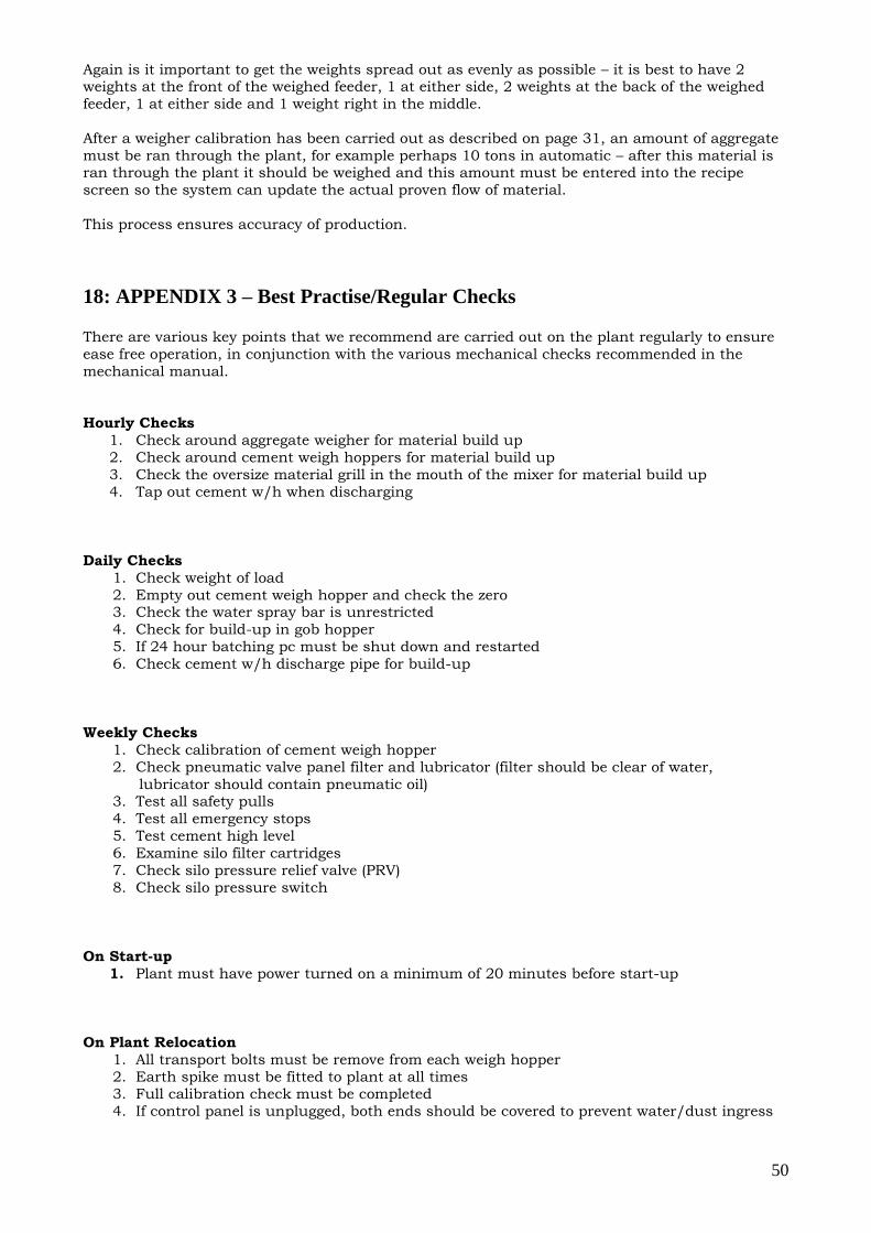
18: APPENDIX 3 – Best Practise/Regular Checks There are various key points that we recommend are carried out on the plant regularly to ensure
ease free operation, in conjunction with the various mechanical checks recommended in the
mechanical manual.
Hourly Checks
1. Check around aggregate weigher for material build up
2. Check around cement weigh hoppers for material build up
3. Check the oversize material grill in the mouth of the mixer for material build up
4. Tap out cement w/h when discharging
Daily Checks
1. Check weight of load
2. Empty out cement weigh hopper and check the zero 3. Check the water spray bar is unrestricted
4. Check for build-up in gob hopper
5. If 24 hour batching pc must be shut down and restarted
6. Check cement w/h discharge pipe for build-up
Weekly Checks
1. Check calibration of cement weigh hopper
2. Check pneumatic valve panel filter and lubricator (filter should be clear of water,
lubricator should contain pneumatic oil) 3. Test all safety pulls
4. Test all emergency stops
5. Test cement high level
6. Examine silo filter cartridges
7. Check silo pressure relief valve (PRV)
8. Check silo pressure switch
On Start-up
1. Plant must have power turned on a minimum of 20 minutes before start-up
On Plant Relocation
1. All transport bolts must be remove from each weigh hopper
2. Earth spike must be fitted to plant at all times 3. Full calibration check must be completed
4. If control panel is unplugged, both ends should be covered to prevent water/dust ingress
51
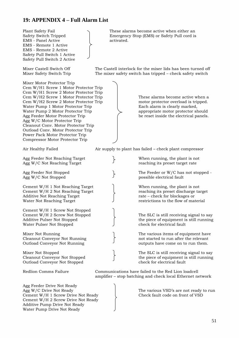
19: APPENDIX 4 – Full Alarm List Plant Safety Fail These alarms become active when either an
Safety Switch Tripped Emergency Stop (EMS) or Safety Pull cord is EMS - Panel Active activated.
EMS - Remote 1 Active
EMS - Remote 2 Active
Safety Pull Switch 1 Active
Safety Pull Switch 2 Active
Mixer Castell Switch Off The Castell interlock for the mixer lids has been turned off
Mixer Safety Switch Trip The mixer safety switch has tripped – check safety switch
Mixer Motor Protector Trip
Cem W/H1 Screw 1 Motor Protector Trip Cem W/H1 Screw 2 Motor Protector Trip
Cem W/H2 Screw 1 Motor Protector Trip These alarms become active when a
Cem W/H2 Screw 2 Motor Protector Trip motor protector overload is tripped.
Water Pump 1 Motor Protector Trip Each alarm is clearly marked,
Water Pump 2 Motor Protector Trip appropriate motor protector should Agg Feeder Motor Protector Trip be reset inside the electrical panels.
Agg W/C Motor Protector Trip
Cleanout Conv. Motor Protector Trip
Outload Conv. Motor Protector Trip
Power Pack Motor Protector Trip
Compressor Motor Protector Trip
Air Healthy Failed Air supply to plant has failed – check plant compressor
Agg Feeder Not Reaching Target When running, the plant is not
Agg W/C Not Reaching Target reaching its preset target rate
Agg Feeder Not Stopped The Feeder or W/C has not stopped -
Agg W/C Not Stopped possible electrical fault
Cement W/H 1 Not Reaching Target When running, the plant is not
Cement W/H 2 Not Reaching Target reaching its preset discharge target Additive Not Reaching Target rate – check for blockages or
Water Not Reaching Target restrictions to the flow of material
Cement W/H 1 Screw Not Stopped
Cement W/H 2 Screw Not Stopped The SLC is still receiving signal to say Additive Pulser Not Stopped the piece of equipment is still running
Water Pulser Not Stopped check for electrical fault
Mixer Not Running The various items of equipment have
Cleanout Conveyor Not Running not started to run after the relevant
Outload Conveyor Not Running outputs have come on to run them.
Mixer Not Stopped The SLC is still receiving signal to say
Cleanout Conveyor Not Stopped the piece of equipment is still running
Outload Conveyor Not Stopped check for electrical fault
Redlion Comms Failure Communications have failed to the Red Lion loadcell
amplifier – stop batching and check local Ethernet network
Agg Feeder Drive Not Ready
Agg W/C Drive Not Ready The various VSD’s are not ready to run
Cement W/H 1 Screw Drive Not Ready Check fault code on front of VSD Cement W/H 2 Screw Drive Not Ready
Additive Pump Drive Not Ready
Water Pump Drive Not Ready
52
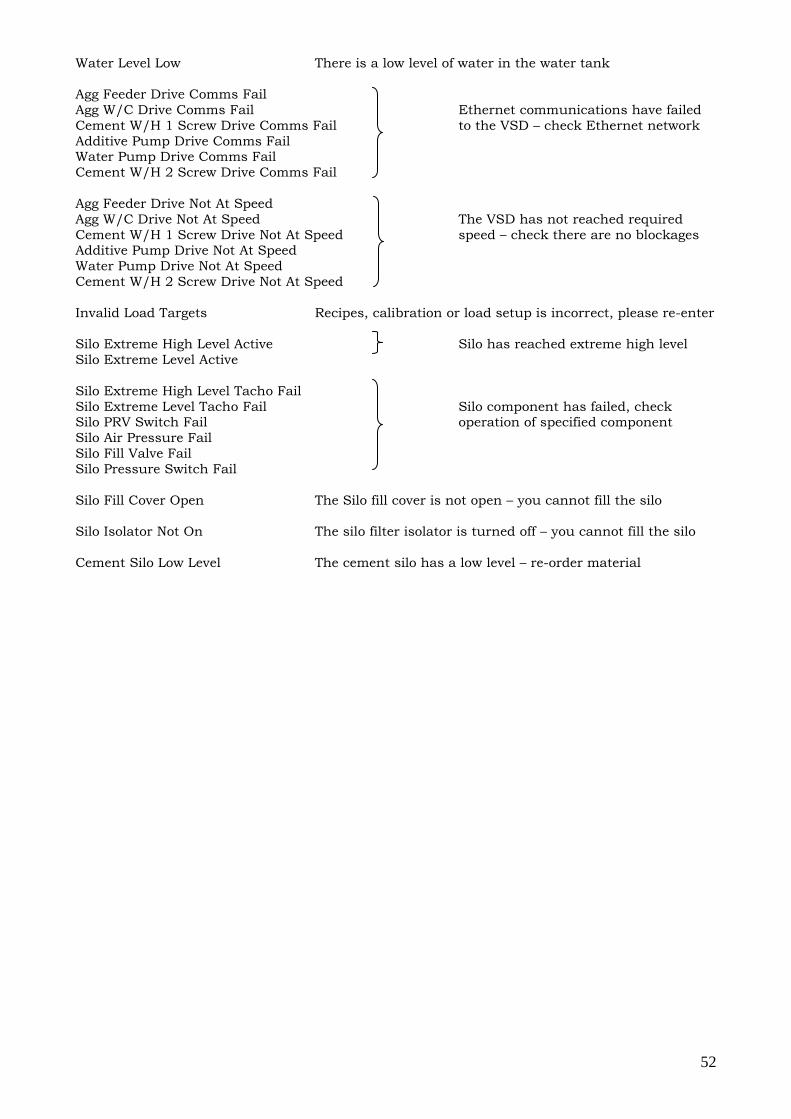
Water Level Low There is a low level of water in the water tank
Agg Feeder Drive Comms Fail
Agg W/C Drive Comms Fail Ethernet communications have failed
Cement W/H 1 Screw Drive Comms Fail to the VSD – check Ethernet network
Additive Pump Drive Comms Fail Water Pump Drive Comms Fail
Cement W/H 2 Screw Drive Comms Fail
Agg Feeder Drive Not At Speed
Agg W/C Drive Not At Speed The VSD has not reached required
Cement W/H 1 Screw Drive Not At Speed speed – check there are no blockages Additive Pump Drive Not At Speed
Water Pump Drive Not At Speed
Cement W/H 2 Screw Drive Not At Speed
Invalid Load Targets Recipes, calibration or load setup is incorrect, please re-enter
Silo Extreme High Level Active Silo has reached extreme high level
Silo Extreme Level Active
Silo Extreme High Level Tacho Fail
Silo Extreme Level Tacho Fail Silo component has failed, check Silo PRV Switch Fail operation of specified component
Silo Air Pressure Fail
Silo Fill Valve Fail
Silo Pressure Switch Fail
Silo Fill Cover Open The Silo fill cover is not open – you cannot fill the silo
Silo Isolator Not On The silo filter isolator is turned off – you cannot fill the silo
Cement Silo Low Level The cement silo has a low level – re-order material


![[SPECO] Catalog - Concrete Batching Plantkr.speco.co.kr/customer_center/pdf/Catalog-ConcreteBatchingPlant.… · Concrete batching plant Silo Top Type Portable Batching Plant Ribbon](https://img.pdfslide.us/doc/110x75/5a9deea57f8b9ada718b6595/speco-catalog-concrete-batching-concrete-batching-plant-silo-top-type-portable.jpg)