Embed Size (px)
Citation preview

RAPID AND FACILE FABRICATION OF 3D-NETWORKED
CIRCULAR MICROFLUIDIC CHANNELS IN PDMS Jiwon Lee, Jungwook Paek, and Jaeyoun Kim*
Department of Electrical and Computer Engineering,
Iowa State University, Ames, Iowa, USA
ABSTRACT In this paper, we propose a new fabrication method which
establishes a simple, rapid, and cost-effective way of generating
3D-networked circular microfluidic (MF) channels. Due to the
growing interests to mimic biological vasculatures [13], recently
techniques to develop circular MF channels with 3D networks are
on demand. By adapting sucrose fibers as eco-friendly sacrificial
templates, we established rapidly prototype pre-designed scheme
which does not require cumbersome fume-hoods or cleanroom
facilities. Moreover, easy control of thicknesses and easy
modification of the structure coming from the water-dissolvable
nature of sucrose fiber makes various structures feasible in 3D-
networked circular MF applications.
INTRODUCTION 2D-networked rectangular microfluidic (MF) channels have
been the workhorse of lab-on-a-chip (LoC) devices. Recent
expansion in the LoC’s scope of application, however, introduced
an increasingly diverse set of requirements on the MF channel’s
cross-sectional shape and topology. Of special interest among
them include the demands for MF channels with circular cross-
section [1-2] and their non-planar 3D deployment [3-4]. While
these new architectures will certainly benefit the on-going efforts
to mimic biological vasculatures, the fabrication schemes have
been complicated and limited as well in their ability to realize MF
channel junctions that are physiologically realistic [5].
Circular MF channels have been fabricated through poly
(dimethylsiloxane) (PDMS) molding of cylindrical templates
predominantly with a variety of templates. Templates with
sufficient strength, such as metal wires and nylon threads were
physically pulled out, but the scheme cannot produce internally
starting and ending MF channels within the PDMS blocks [6]. The
use of chemically etchable templates allowed more complex
geometries but inevitably brought complicated chemical processes
which in general are time-consuming and high-temperature
processes. As an alternative, rectangular MF channels were
circularized by filling them with curable liquid and applying a
strong air stream which bores cylindrical openings. Such a scheme
is advantageous for its applicability to conventionally prepared 2D
MF networks, whereas it required additional steps involving
special solvents.
The realization of non-planar MF networks to study biological
systems has also been pursued actively. Layer-by-layer assembly
of planar structures [6-7], with vertical via connecting MF
channels in different layers, has been the most commonly adopted
whereas it was not true 3D MF channels trajectories. Instead, in
the plug-in-and-mold scheme, PDMS MF “pipes” were cut out
from a 2D MF network prepared in advance and then manually
shaped into 3D topologies before getting immersed in liquid-phase
PDMS to be cured. Another more recent scheme, omni-directional
printing, fabricated 3D MF channel networks by depositing
filaments of fugitive ink that can be liquefied and drained after the
embedding material got solidified [8].
Thus, a new fabrication scheme should accomplish both
circular MF channels and 3D trajectories simultaneously. In
particular, it is highly desired to establish a simple and accessible,
yet flexible, rapid prototyping technique for 3D-networed circular
MF channels. Some of the previously mentioned schemes actually
meet the dual requirements. The omni-directionally printed 3D
MF channels [8] exhibit circular cross-section thanks to the
filamentary morphology of the nozzle-injected ink. The schemes
in Refs [8], [9], and [10] also accomplished the dual goal using
3D-shapable cylindrical templates as well as complex instruments
and materials. These schemes, however, are not suitable for
readily accessible rapid prototyping or compatible with PDMS.
Another attempt, the simple overlapping method of two cylindrical
templates would result in a physiologically un-realistic junction
shape with little contact area. The formation of a proper junction
requires attaching one end of the template to the side of another.
With the template materials not providing effective ways for the
task, the authors of the previous work had to fuse the overlapping
areas mechanically or thermally, a cumbersome process that may
further deform the junction shape.
In this work, we demonstrate a new scheme for rapid
prototyping of MF channels with circular cross-sections and 3D
trajectories, with an emphasis on realizing physiologically realistic
channel branches. Our work differs from the previous ones in
providing a scheme to rapidly prototype pre-designed, rather than
randomly shaped, 3D networks of circular MF channels. We also
focus on achieving the dual goal using low-temperature, water-
based processes so that the need for fume-hoods or cleanroom
facilities can be eliminated. In this regard, we established
techniques to make junctions between the sucrose fiber templates
and devised methods to efficiently control the trajectories of the
templates. The technique is also compatible with a rapid
prototyping method, the conventional PDMS molding process. In
addition, we exploited the wide variety in the achievable shape of
the sucrose template to implement structures other than MF
channels as well.
Figure 1: Process flow (a) sucrose is heated on 200°C for 15min,
(b) at light brown color, ramp down to 125°C for 10min, (c) pull
sucrose fibers at 0.1~ 0.5m/s, (d) coil it around a cylindrical
PDMS base template
(a) (b)
(c) (d)
9780964002494/HH2012/$25©2012TRF 213 Solid-State Sensors, Actuators, and Microsystems WorkshopHilton Head Island, South Carolina, June 3-7, 2012

MATERIAL SELECTION The key enabling factor is the use of sucrose as the sacrificial
material. It is highly water-soluble and can be pulled into
cylindrical fibers at <200°C for various thicknesses. The resulting
fibers also exhibit mechanical strength and surface smoothness
adequate for handling/shaping and formation of transparent MF
channels, respectively. These advantageous features of sugar-
based sacrificial template materials have been exploited formerly.
Bellan et al [11] fabricated 3D artificial vascular structures by
melt-spinning random sugar fiber networks with a cotton-candy
machine and then replicating them with PDMS, epoxy, and poly
(caprolactone). Li et al [12] also fabricated bundles of poly-(L-
lactic acid) (PLLA) tubules for nerve scaffolds by coating sucrose
fibers with PLLA and then dissolving the fibers. Former studies,
however, are targeted random or simple tubular structures only.
We fully exploit the mechanical and thermal properties of sucrose
fiber to realize pre-designed templates in a more controlled
fashion.
PDMS molding, which is popularly used for its easy curing
mechanism, transparency, and flexibility, is selected as to generate
MF structures. Due to the temperature budget and chemical-free
dissolving mechanism of sucrose, it is suitable to be used with
PDMS as well as it enables the fabrication of complex MF
channels in bench-top settings. Figure 2 offers an example of the
structure created with sucrose as a sacrificial 3D template for the
PDMS based MF structure.
Figure 2: Microscopic images of a PDMS MF junction made with
two sucrose fibers: (a) original sucrose fiber assembly, (b) after
dissolving the sucrose, (c-d) red food dye was injected to visualize
the junction
FABRICATION METHOD Preparation of sucrose fibers
Steps for sucrose fiber pulling are described in Figs. 1(a)-(c).
First, crystalline sucrose was melted at 200°C. Upon turning into
light-brown color after 10-15 min, the temperature was ramped
down to 125°C and maintained for additional 10 min. This
particular caramelization temperature extends the duration of the
caramelized state up to 3 hours. Then sucrose fibers were pulled at
0.1-0.5m/s with an optical fiber. The diameter of the pulled
sucrose fiber was varied between few tens to several hundred
micrometers rely on the speed. Both manual pulling and
micromanipulator automated pulling is possible depending on the
length and the thickness of fiber required.
Assembly of sucrose fibers The water-soluble nature and high tensile strength of the
sucrose fibers facilitates their manual handling and assembly.
Sucrose fibers pulled out of caramelized sucrose instantly solidify.
Subsequently, pulled fibers were assembled into a 3D network on
or around the base PDMS template. First, the PDMS base plate
was made with standard PDMS process. Sylgard184 base and
curing agent were mixed at 10:1 ratio and cured for 3 hours at
60°C. Then, two or more sucrose fibers are located on top of the
base plate, used as substrate of final product. Subsequently, one
end of a sucrose fiber was closely applied to the cylindrical body
of another sucrose fiber to create junctions. Then, two sucrose
fibers were easily attached to each other by applying small amount
of water. Figure 2(a) shows original sucrose fibers made with
above method. To secure the bonding, adhesives made with
additional sucrose and water as 2:3 weight-ratios and heated on
90°C hot plate temperature could also be used. In addition,
sucrose-water adhesives make different junction angles feasible,
but large quantity of them can cause residues while water should
be continuously supplied to maintain the optimum weight-ratio.
Not only multiple branches were made by connecting sucrose
fibers, but also with a lengthy single fiber we could make different
types of patterns. In general, we can easily withdraw a couple
meters of a thin sucrose fiber. Especially when the diameter of
sucrose fiber is less than 50µm, it is flexible enough to be coiled or
located around any shapes depending on the PDMS template. For
instance, a sucrose fiber can be coiled around a PDMS cylinder to
make a solenoidal MF structure as illustrated in Fig. 1(d).
Dissolving of Sucrose fibers After being assembled on or around the PDMS base template,
sucrose template structure was placed inside a container and
subsequently filled with another batch of PDMS. Once PDMS is
completely cured, the sucrose fiber assembly was dissolved in
warm (~70°C) water. This low temperature, water-based template
removal makes our scheme much simpler than the other methods
relying on chemical etching. To aid the complete removal of
sucrose, flow of warm water was injected with a syringe.
Figure 3: Microscopic images of a 25µm-diameter MF channel
forming a 3D solenoidal network with a 5mm-diameter size core
25 µµµµm
(a) (b)
(c) (d)
500µm 500µm
500µm 500µm
214
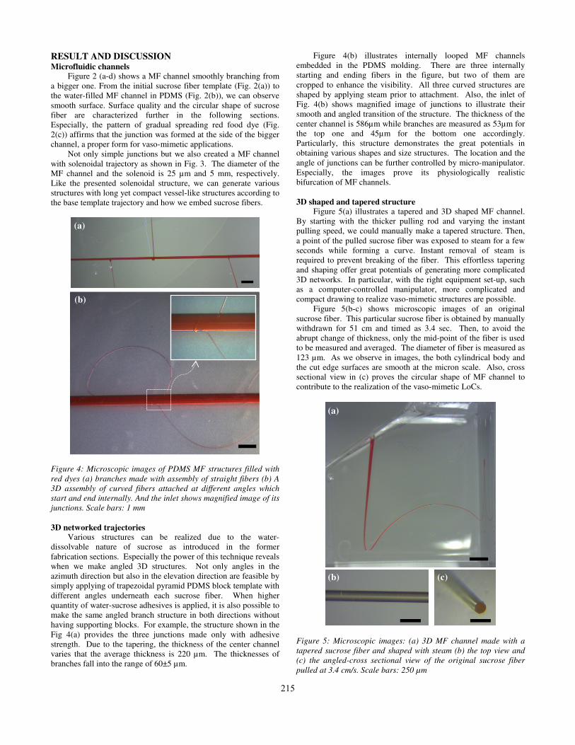
RESULT AND DISCUSSION Microfluidic channels
Figure 2 (a-d) shows a MF channel smoothly branching from
a bigger one. From the initial sucrose fiber template (Fig. 2(a)) to
the water-filled MF channel in PDMS (Fig. 2(b)), we can observe
smooth surface. Surface quality and the circular shape of sucrose
fiber are characterized further in the following sections.
Especially, the pattern of gradual spreading red food dye (Fig.
2(c)) affirms that the junction was formed at the side of the bigger
channel, a proper form for vaso-mimetic applications.
Not only simple junctions but we also created a MF channel
with solenoidal trajectory as shown in Fig. 3. The diameter of the
MF channel and the solenoid is 25 µm and 5 mm, respectively.
Like the presented solenoidal structure, we can generate various
structures with long yet compact vessel-like structures according to
the base template trajectory and how we embed sucrose fibers.
Figure 4: Microscopic images of PDMS MF structures filled with
red dyes (a) branches made with assembly of straight fibers (b) A
3D assembly of curved fibers attached at different angles which
start and end internally. And the inlet shows magnified image of its
junctions. Scale bars: 1 mm
3D networked trajectories Various structures can be realized due to the water-
dissolvable nature of sucrose as introduced in the former
fabrication sections. Especially the power of this technique reveals
when we make angled 3D structures. Not only angles in the
azimuth direction but also in the elevation direction are feasible by
simply applying of trapezoidal pyramid PDMS block template with
different angles underneath each sucrose fiber. When higher
quantity of water-sucrose adhesives is applied, it is also possible to
make the same angled branch structure in both directions without
having supporting blocks. For example, the structure shown in the
Fig 4(a) provides the three junctions made only with adhesive
strength. Due to the tapering, the thickness of the center channel
varies that the average thickness is 220 µm. The thicknesses of
branches fall into the range of 60±5 µm.
Figure 4(b) illustrates internally looped MF channels
embedded in the PDMS molding. There are three internally
starting and ending fibers in the figure, but two of them are
cropped to enhance the visibility. All three curved structures are
shaped by applying steam prior to attachment. Also, the inlet of
Fig. 4(b) shows magnified image of junctions to illustrate their
smooth and angled transition of the structure. The thickness of the
center channel is 586µm while branches are measured as 53µm for
the top one and 45µm for the bottom one accordingly.
Particularly, this structure demonstrates the great potentials in
obtaining various shapes and size structures. The location and the
angle of junctions can be further controlled by micro-manipulator.
Especially, the images prove its physiologically realistic
bifurcation of MF channels.
3D shaped and tapered structure Figure 5(a) illustrates a tapered and 3D shaped MF channel.
By starting with the thicker pulling rod and varying the instant
pulling speed, we could manually make a tapered structure. Then,
a point of the pulled sucrose fiber was exposed to steam for a few
seconds while forming a curve. Instant removal of steam is
required to prevent breaking of the fiber. This effortless tapering
and shaping offer great potentials of generating more complicated
3D networks. In particular, with the right equipment set-up, such
as a computer-controlled manipulator, more complicated and
compact drawing to realize vaso-mimetic structures are possible.
Figure 5(b-c) shows microscopic images of an original
sucrose fiber. This particular sucrose fiber is obtained by manually
withdrawn for 51 cm and timed as 3.4 sec. Then, to avoid the
abrupt change of thickness, only the mid-point of the fiber is used
to be measured and averaged. The diameter of fiber is measured as
123 µm. As we observe in images, the both cylindrical body and
the cut edge surfaces are smooth at the micron scale. Also, cross
sectional view in (c) proves the circular shape of MF channel to
contribute to the realization of the vaso-mimetic LoCs.
Figure 5: Microscopic images: (a) 3D MF channel made with a
tapered sucrose fiber and shaped with steam (b) the top view and
(c) the angled-cross sectional view of the original sucrose fiber
pulled at 3.4 cm/s. Scale bars: 250 µm
(a)
(b)
(b) (c)
(a)
215

Figure 6: (a) 3D AFM scan of 16 µm2 area of the outer surface of
sucrose fiber, (b) a microscopic image of its original fiber
We further investigated surface roughness of the sucrose fiber
by using AFM (atomic force microscopy) scan. Figure 6 shows
the 3D AFM scans of 16 µm2 area. The measurement scan was
carried out over ten randomly selected locations on a single fiber.
Then, Nanoscope program is used to characterize the surface. The
root mean square roughness value was found to be 1.1±0.4nm,
confirming its excellent surface smoothness.
CONCLUSION In summary, we established a simple, rapid, and cost-effective
fabrication scheme to realize 3D networks of circular MF channels
by adopting sucrose as the sacrificial material. Various MF
structures shown in the manuscript prove the great potential of our
fabrication method. The excellent chemical, mechanical, and
thermal properties of sucrose allowed a high level of flexibility in
the attainable network topologies. Especially, the easy tapering
and curving modification of the sucrose template can be greatly
used for the formation of physiologically realistic junctions.
ACKNOWLEDGEMENT The authors were supported by NSF CAREER award
(0954845).
REFERENCES [1] M. Abdelgawad, C. Wu, W.-Y. Chien, W. R. Geddie, M. A.
S. Jewett and Y. Sun, "A fast and simple method to fabricate
circular microchannels in polydimethylsiloxane (PDMS),"
Lab on a Chip, 11, 545 (2011).
[2] S.-H. Song, C.-K. Lee, T.-J. Kim, I.-C. Shin, S.-C. Jun and
H.-I. Jung, “A rapid and simple fabrication method for 3-
dimensional circular microfluidic channel using metal wire
removal process,” Microfluid Nanofluid, 9, 533 (2010).
[3] H. Wu, T. W. Odom, D. T. Chiu, and G. M. Whitesides,
"Fabrication of Complex Three-Dimensional Microchannel
Systems in PDMS," J. Am. Chem. Soc., 125, 554-559 (2012).
[4] Y. Luo and R. N. Zare, "Perforated membrane method for
fabricating three-dimensional polydimethylsiloxane
microfluidic devices," Lab Chip, 8, 1688 (2008).
[5] J. M. Rosano, N. Tousi, R. C. Scott, B. Krynska, V. Rizzo, B.
Prabhakarpandian, K. Pant, S. Sundaram, and M. F. Kiani, "A
physiologically realistic in vitro model of microvascular
networks," Biomed Microdevices, 11, 5 (2009).
[6] M. K. S. Verma, A. Majumder, and A. Ghatak, "Embedded
Template-Assisted Fabrication of Complex Microchannels in
PDMS and Design of a Microfluidic Adhesive," Langmuir,
22, 10291-10295 (2006).
[7] Y. Jia, J. Jiang, X. Ma, Y. Li, H. Huang, K. Cai, S. Cai, and
Y. Wu, "PDMS microchannel fabrication technique based on
microwire-molding," Chinese Science Bulletin, 53, 3928-
3936 (2008).
[8] W. Wu, A. DeConinck, and J. A. Lewis, "Omnidirectional
Printing of 3D Microvascular Networks," Advanced
Materials, 23, H178-H183 (2011).
[9] Y. Du, M. Ghodousi, H. Qi, N. Haas, W. Xiao, and A.
Khademhosseini, "Sequential assembly of cell-laden hydrogel
constructs to engineer vascular-like microchannels,"
Biotechnology and Bioengineering, 108, 1693-1703 (2011).
[10] C. Xia and N. X. Fang, "3D microfabricated bioreactor with
capillaries," Biomedical Microdevices 11, 1309-1315 (2009).
[11] L. M. Bellan, S. P. Singh, P. W. Henderson, T. J. Porri, H. G.
Graighead and J. A. Spector, “Fabrication of an artificial 3-
dimensional vascular network using sacrificial sugar
structures,” Soft Matter, 5, 1354 (2009)
[12] J. Li, T. A. Rickett, and R. Shi, “Biomimetic Nerve Scaffolds
with aligned Intraluminal Microchannels: A “Sweet”
Approach to Tissue Engineering,” Langmuir, 25, 1813 (2009)
[13] L. K. Fiddes, N. Raz, S. Srigunapalan, E. Tumarkan, C. A.
Simmons, A. R. Wheeler, E. Kumacheva, "A circular cross-
section PDMS microfluidics system for replication of
cardiovascular flow conditions," Biomaterials, 31, 3459
(2010).
CONTACT *Jaeyoun Kim, tel: +1-515-294-4214; [email protected]
(b)
500µm
(a)
216


![Facile Fabrication of SingleCrystalDiamond … mechanical properties are poised ... include direct FIB machining, [8] ... The quartz handle is prepared for diamond](https://img.pdfslide.us/doc/110x75/5ac8a4d97f8b9a40728cf061/facile-fabrication-of-singlecrystaldiamond-mechanical-properties-are-poised.jpg)