Embed Size (px)
Citation preview
Rapid-action intermittent blowdown valve
PA 46
PA 47
MPA 46
MPA 47
Original Installation Instructions
818447-02
Contents
Foreword ............................................................................................................................................ 4 Availability ............................................................................................................................................. 4 Formatting features in the document ...................................................................................................... 4 Safety .................................................................................................................................................. 5 Use for the intended purpose ................................................................................................................. 5 Basic safety notes ................................................................................................................................. 5 Information on property damage or malfunctions ..................................................................................... 7 Qualification of personnel ....................................................................................................................... 7 Typographic features of warning notes .................................................................................................... 7 Formatting features for warnings of property damage .............................................................................. 7 Description ......................................................................................................................................... 8 Scope of supply and equipment specification .......................................................................................... 8 Optional extras .................................................................................................................................... 12 Application of European Directives ........................................................................................................ 12 Task and function ................................................................................................................................ 13 Storing and transporting the equipment ......................................................................................... 13 Storing the equipment ......................................................................................................................... 13 Transporting the equipment ................................................................................................................. 14 Mounting and connecting the equipment ....................................................................................... 15 Preparing installation ........................................................................................................................... 15 Connecting the equipment ................................................................................................................... 15 Mounting the lever ............................................................................................................................... 17 Positioning the lever ............................................................................................................................ 18 Starting up the equipment ............................................................................................................... 19 Operating the equipment ................................................................................................................. 20 Operating the PA 46 and PA 47 ........................................................................................................... 20 Operating the MPA 46 and MPA 47 ...................................................................................................... 22 After operation ................................................................................................................................. 23 Removing external dirt deposits ............................................................................................................ 23 Required tools for servicing .................................................................................................................. 24 Tightening torques ............................................................................................................................... 24 Maintaining the equipment ................................................................................................................... 25 Servicing the equipment and installing spare parts ................................................................................ 27 Retrofitting the equipment .................................................................................................................... 34 Troubleshooting ............................................................................................................................... 38 Putting the equipment out of operation .......................................................................................... 39 Removing harmful substances .............................................................................................................. 39 Removing the equipment ..................................................................................................................... 39 Re-using equipment after storage ......................................................................................................... 40 Disposing of the equipment .................................................................................................................. 41 Technical data .................................................................................................................................. 42

Dimensions and weights ...................................................................................................................... 42 Flow diagram ...................................................................................................................................... 46 Control pressure for MPA 46 and MPA 47 ............................................................................................ 47 Pressure & temperature ratings ........................................................................................................... 48 Manufacturer's declaration ............................................................................................................ 50
4
Foreword This installation & operating manual will help you use the following types of equipment safely and efficiently for their intended purpose.
Rapid-action intermittent blowdown valve PA 46 (manual actuation)
Rapid-action intermittent blowdown valve PA 47 (manual actuation)
Rapid-action intermittent blowdown valve MPA 46 (automatic actuation)
Rapid-action intermittent blowdown valve MPA 47 (automatic actuation)
These types will be called equipment in this document.
This installation & operating manual is intended for anyone commissioning, using, operating, servicing, cleaning or disposing of this equipment and, in particular, for professional after-sales service technicians, qualified personnel and authorised and trained staff.
All of these persons must read and understand the content of this installation & operating manual.
Following the instructions given in this installation & operating manual helps avoiding danger and increases the reliability and service life of the equipment. Please note that in addition to the instructions given in this installation & operating manual you must also observe all locally applicable rules and regulations concerning the prevention of accidents as well as approved safety guidelines for good professional practice.
Availability Keep this installation & operating manual together with the plant documentation for future reference. Make sure that this installation & operating manual is available to the operator.
The installation & operating manual is part of the equipment. Please hand over this installation & operating manual when selling the equipment or passing it on.
You can find further information, instructions and details of equipment accessories in the respective manufacturer documentation. These documents are regarded as belonging to this installation & operating manual. Keep these documents together with this installation & operating manual. Hand over this installation & operating manual if you sell or pass on the equipment to a third party.
Formatting features in the document Certain text elements of this installation & operating manual feature a specific typographic design. You can easily distinguish the following text elements:
Standard text
Cross-reference
Listing
Sub-items in listings
Steps for action.
Here you will find additional useful information and tips serving to assist you in using the equipment to its fullest potential.
5
Safety
Use for the intended purpose The following rapid-action intermittent blowdown valves are installed in pipes to discharge boiler blowdown water.
Rapid-action intermittent blowdown valve PA 46 (manual actuation)
Rapid-action intermittent blowdown valve PA 47 (manual actuation)
Rapid-action intermittent blowdown valve MPA 46 (automatic actuation)
Rapid-action intermittent blowdown valve MPA 47 (automatic actuation)
The equipment is designed for discharging boiler blowdown water with non-metallic solids from steam boilers.
The equipment must only be used within the allowable pressure and temperature limits and only if the chemical and corrosive influences on the equipment are taken into account.
The pipe between the steam boiler and the equipment must not be longer than 2 metres.
Correct use includes compliance with the instructions given in this installation & operating manual, in particular obedience to all safety instructions.
Usage for the intended purpose also includes reading and adhering to all instructions in the installation and operating manual for the actuator (if present).
Any other use of the equipment is considered to be improper.
Note that the equipment is also used incorrectly if the materials of the equipment are not suitable for the fluid.
The equipment is also considered to be used improperly if:
the equipment is not in proper working condition when being used
the equipment is operated or serviced by unqualified personnel. The personnel must have the necessary qualification and experience for the required work.
Basic safety notes
Explosion hazard
Explosion risk if equipment is used that is not suitable for the environmental conditions. When using the equipment in explosion risk areas make sure that:
The permissible surface temperature of the equipment for the place of installation must not be exceeded.
If electrically insulated equipment is installed appropriate measures must be taken to discharge any static electricity between pipe flanges.
The heat generated by friction caused by moving parts that do not run smoothly can cause explosions. Make sure that all moving parts can operate smoothly.
When carrying out welding work in order to install or remove the equipment flying sparks may be generated that can cause fire or explosion. Observe any on-site regulations for fire and explosion prevention. Only qualified personnel is allowed to mount or remove the equipment or its components.
6
Risk of severe injuries
The equipment is under pressure during operation and may be hot. Before carrying out any work on the equipment make sure that the following requirements are met:
The pipes must be depressurized (0 bar).
The fluid must be completely removed from the pipes and the equipment.
During work on the equipment the installation must be switched off and protected against unauthorised or unintended activation.
The pipes and the equipment must have cooled down to room temperature (approx. 20 °C).
If the equipment is used in contaminated areas there is a risk of severe injuries or death caused by harmful substances in or on the equipment. Before working on the equipment make sure that it is completely decontaminated. Always wear the protective clothing prescribed for contaminated areas when working on the equipment.
The equipment must only be used with fluids that do not attack the material and the gaskets and sealings of the equipment. Otherwise leaks may occur and hot or toxic fluid could escape.
The equipment and its component parts must only be mounted or removed by qualified personnel. A qualified person must be acquainted with and experienced in the following:
Making pipe connections.
Selecting suitable lifting gear and understanding the rules for its safe use.
Working with dangerous (contaminated, hot or pressurized) fluids.
If the admissible temperature and pressure limits are exceeded the equipment may be destroyed and hot or pressurized fluid may escape. Make sure that the equipment is only operated within the admissible service range and limits. For more information on limits and pressure & temperature ratings see name plate and the section "Technical Data".
The moving parts of the equipment can cause severe injuries or death. Make sure that nobody is standing close to these moving parts or can touch them while the equipment is operating. Before working on the equipment make sure that the power supply to the actuator is cut off and cannot be switched on accidentally.
If the stuffing box is leaking there is a risk of severe injuries caused by escaping hot fluid. Use the equipment only if it is in proper working condition. Replace any leaking stuffing box seal.
Risk of minor injuries
Sharp edges on internals present the danger of cuts to hands. Always wear industrial gloves when servicing the equipment.
If the support of the equipment during installation is insufficient the equipment might fall down, thereby causing bruises or injuries. Make sure the equipment is safely held in place during installation and cannot fall down. Wear protective safety footwear.
7
Information on property damage or malfunctions Malfunctions will occur if the equipment is
installed in a wrong position or with the flow arrow pointing in the opposite direction of the fluid flow. This may result in damage to the equipment or the installation. Make sure that the flow arrow on the equipment body matches the indicated direction of the fluid flow in the pipe.
If the material is unsuitable for the fluid, increased wear may occur and fluid may escape. Make sure that the material is suitable for the fluid used in your installation.
Qualification of personnel A qualified person must be acquainted with and experienced in the following:
the pertinent on-site rules and regulations for preventing fire and explosions as well as industrial safety regulations
working on pressure equipment
making pipe connections
working with dangerous (hot or pressurized) fluids
lifting and transporting loads
observing all notes and instructions in this installation & operating manual and the applicable documents
connecting the power supply of the actuator
Typographic features of warning notes
DANGER
Notes with the heading DANGER warn against imminent dangerous situations that can lead to death or serious injuries.
WARNING
Notes with the heading WARNING warn against possibly dangerous situations that could lead to death or serious injuries.
CAUTION
Notes with the heading CAUTION warn against dangerous situations that could lead to minor or moderate injuries.
Formatting features for warnings of property damage
Attention! This information warns of a situation leading to property damage.
8
Description
Scope of supply and equipment specification
Scope of supply
For equipment types PA 46 and PA 47, delivery includes the following:
An intermittent blowdown valve
A lever
This installation & operating manual
For equipment types MPA 46 and MPA 47, delivery includes the following:
An intermittent blowdown valve with diaphragm actuator
This installation & operating manual
Type PA 46 and PA 47 valves have the lever included in the packaging. Type MPA 46 and MPA 47 valves are delivered ready for installation.
Equipment specification
PA and MPA valves have different types of actuator. Below, the two types of actuator are shown in separate diagrams. The body with inner parts is identical in both valves and is shown separately.
9
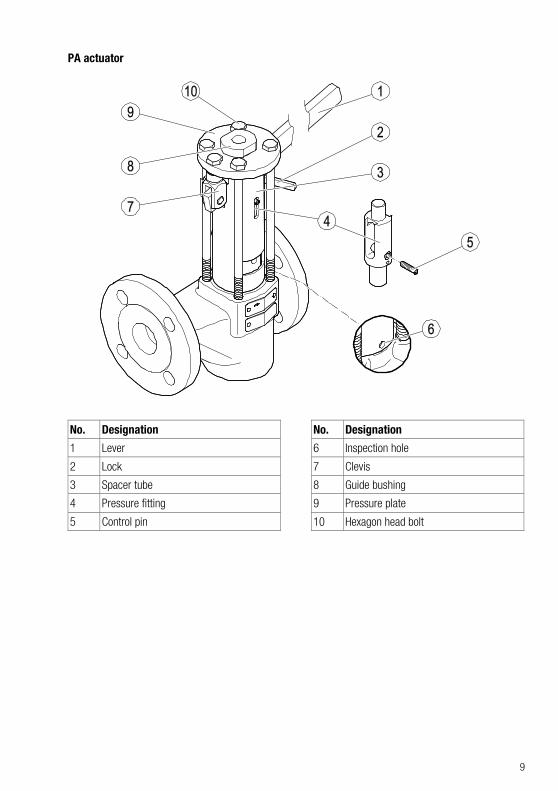
PA actuator
No. Designation
1 Lever
2 Lock
3 Spacer tube
4 Pressure fitting
5 Control pin
No. Designation
6 Inspection hole
7 Clevis
8 Guide bushing
9 Pressure plate
10 Hexagon head bolt
10
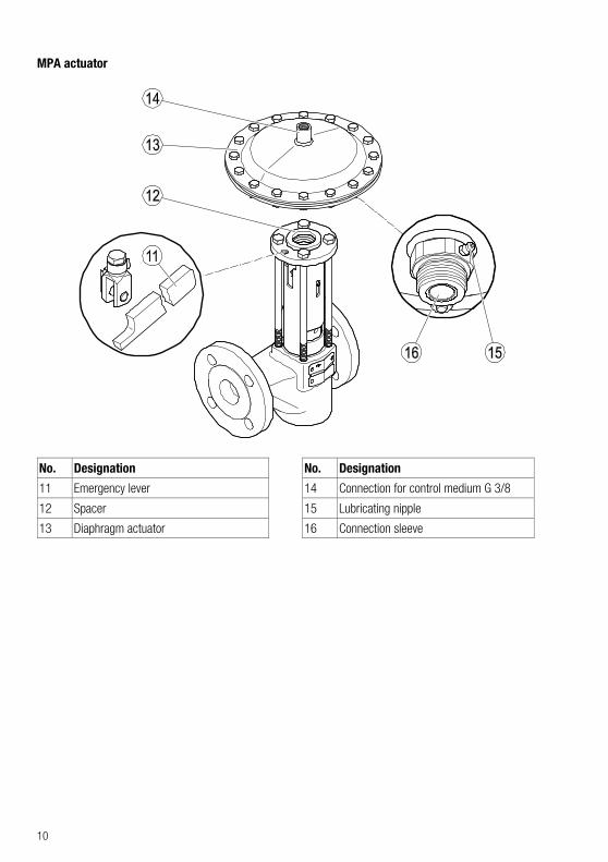
MPA actuator
No. Designation
11 Emergency lever
12 Spacer
13 Diaphragm actuator
No. Designation
14 Connection for control medium G 3/8
15 Lubricating nipple
16 Connection sleeve
11
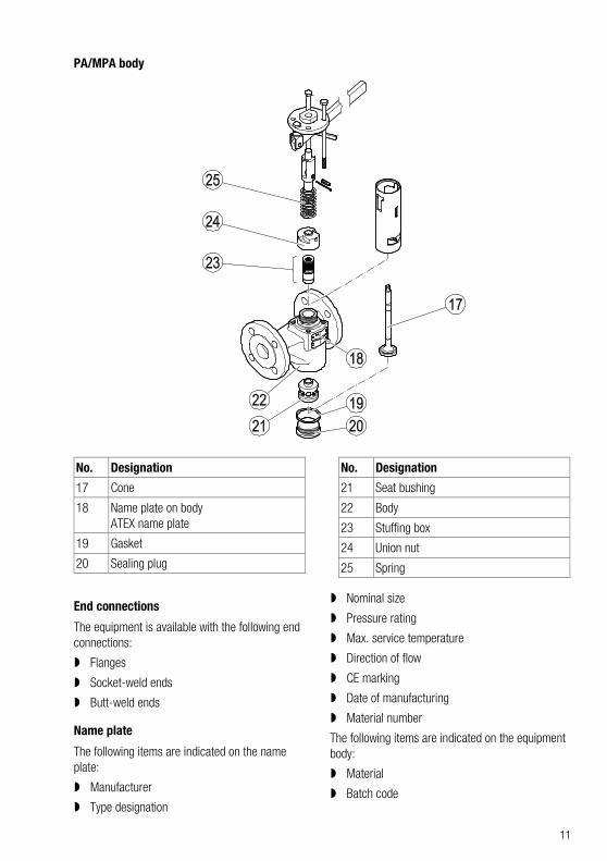
PA/MPA body
No. Designation
17 Cone
18 Name plate on body ATEX name plate
19 Gasket
20 Sealing plug
No. Designation
21 Seat bushing
22 Body
23 Stuffing box
24 Union nut
25 Spring
End connections
The equipment is available with the following end connections:
Flanges
Socket-weld ends
Butt-weld ends
Name plate
The following items are indicated on the name plate:
Manufacturer
Type designation
Nominal size
Pressure rating
Max. service temperature
Direction of flow
CE marking
Date of manufacturing
Material number
The following items are indicated on the equipment body:
Material
Batch code
12
Optional extras The following add-on equipment is available:
Assembly kit 335130 for retrofitting the drive of an existing MPA 26 or MPA 27 in a PA 46 or PA 47 to upgrade them to an MPA 46 or MPA 47 (guide bushing with washer and spacer disc)
Diaphragm actuator 335093 for PA 46 or PA 47 (diaphragm actuator, shim)
TA program controller for MPA 46 and MPA 47
Retrofit kit 335197 containing proximity switch for MPA 46 and MPA 47 (one limit switch):
proximity switch with angle plug
Isolation amplifier
Bracket
2 shims
2 hex nuts
Follower pin
Installation & operating manual
Retrofit kit 335140 containing proximity switch for MPA 46 and MPA 47 (two limit switches):
2 proximity switches with angle plug
2 isolation amplifiers
2 brackets
4 shims
4 hex nuts
Follower pin
Installation & operating manual
Emergency lever for MPA:
Emergency lever
Clevis G 10 × 20, DIN 71752
Hexagon head bolt
Application of European Directives
Pressure Equipment Directive
The equipment conforms to this Directive (see "Declaration of Incorporation" section) and can be used for the following media:
Fluids of group 2
ATEX Directive
Pay attention to the instructions below if using in potentially explosive environments.
The equipment has classification: CE Ex II 2G/D c X.
For use in potentially explosive atmospheres in zones (surrounding atmosphere to Directive 1999/92/EC) 1, 2, 21 and 22, please read and observe the following information:
The sign "X" in the Ex label signifies that operation at an excessive surface temperature caused by the medium must be avoided. The equipment itself does not generate additional surface temperatures.
Once installed, static electricity may arise between the equipment and the connected system. During use in potentially explosive atmospheres, the discharge or prevention of possible electrostatic charging is the responsibility of the manufacturer or owner of the system. If there is a possibility that medium might escape, e.g. via actuating devices or leaks in screwed couplings, the manufacturer or owner of the system must take this into consideration when dividing the area into zones.
If the MPA has a pneumatic drive, if incorrectly discharged the exhaust air (compressed air) required for operation can lead to swirls of potentially explosive dust.
13
Task and function
Purpose
The equipment is designed for the manual or automatic discharge of boiler blowdown water with non-metallic solids from steam boilers.
Function
Type PA 46 and PA 47 valves are intended for manual operation. For the blowdown process, the valve is opened fully by hand with the lever for around two to three seconds. The plug, which is compressed by a spring, is pushed out of the seat bushing. The sludge is discharged through the open valve. Slowly releasing the lever causes spring force to push the plug into the seat bushing (rapid closing). The valve is closed.
The position of the valve is indicated by the control pin. When the valve is open, the control pin is in its uppermost position; when closed, in its bottom position. Optional limit switches are available, with which the valve position can be transmitted to a control system.
Type MPA 46 and MPA 47 valves are equipped with a diaphragm actuator for automatic operation. Compressed air or pressurised water is used as the control medium. For blowdown, the valve is opened by the diaphragm actuator.
The opening signal can be sent by various controllers:
the TA program controller, see data sheet
a blowdown controller LRR 1-40, LRR 1-52 or LRR 1-53, see data sheet, or
the SPECTORcontrol with CAN bus
Storing and transporting the equipment
Attention! Equipment can be damaged if stored or transported improperly.
Close all openings with the sealing plugs or covers supplied with the equipment or use similar sealing covers.
Protect the equipment against moisture and corrosive atmospheres.
Please contact the manufacturer if the specified transport and/or storage requirements cannot be met.
Storing the equipment Please observe the following items when storing
the equipment:
Do not store the equipment for more than 12 months.
Use the supplied sealing plugs or other suitable seal caps in order to seal off all openings of the equipment.
Protect the sealing surfaces and contact areas against mechanical damage.
Protect the equipment and all components against hard shocks and impacts.
Store the equipment only in closed rooms that meet the following environmental conditions:
Air humidity below 50 %, not condensing
Indoor air: clean, salt-free and non-corrosive
Temperature 5–40 °C.
Make sure that all these requirements are always met when storing the equipment.
Please contact the manufacturer if you cannot comply with the recommended storage conditions.
14
Transporting the equipment
DANGER
Risk of bruises if the equipment or component parts fall down.
Use suitable lifting gear when moving or lifting the equipment and/or component parts.
Make sure that the equipment cannot topple over.
Make sure that nobody is standing below the lifted equipment.
The lifting gear must be of sufficient strength for the equipment including the actuator.
Meet the requirements for storage also when transporting the equipment.
Prior to transport seal off connections with sealing plugs.
If you do not have the sealing plugs supplied with the equipment use appropriate seal caps to seal off the connections.
For short distances (only a few metres) you can transport the equipment unpacked.
When transporting the equipment over larger distances use the original packaging.
If you do not have the original packaging use a box that protects the equipment adequately against corrosion and physical damage.
For a short period of time the equipment may be transported even if the temperature is below 0 °C, provided that the equipment is completely empty and dry.
15
Mounting and connecting the equipment
Preparing installation Take the equipment out of the transport
packaging.
Check the equipment for transport damage.
Contact the manufacturer if you detect any kind of shipping damage.
When supplied by the factory, the connections may be sealed off with sealing plugs.
Remove sealing plugs before mounting the equipment.
Keep the sealing plugs and the packing for further use.
DANGER
Personnel working on pipes are exposed to safety risks and may suffer severe injuries, poisoning or even loss of life.
Make sure that no hot or hazardous fluid is in the equipment or the pipes.
Make sure that the pipes upstream and downstream of the equipment are depressurised.
Make sure that the installation is switched off and protected against unauthorised or unintended activation.
Make sure that the equipment and the pipes have cooled down to room temperatures.
Wear protective clothing that is suitable for the fluid and, if necessary, wear protective gear.
For more information on suitable protective clothing and safety gear refer to the safety data sheet of the fluid in question.
Drain pipes until they are empty.
Switch the installation off and protect it against unauthorised or unintended re-activation.
To avoid waterhammer make sure that the pipe downstream of the equipment has a down gradient.
If this is not possible provide other means to ensure draining.
Connecting the equipment
DANGER
Incorrectly connected equipment can result in accidents with extremely severe injuries or death.
Make sure that only specialist personnel connect the equipment to the pipe.
Make sure that the direction of flow in the pipe matches the flow direction arrow on the equipment.
Make sure that the connected pipe does not subject the body to any stress (forces or torques) during installation and operation.
Specialist personnel must have knowledge and experience of the type of pipe connection used.
Attention! Equipment will be damaged if the end connections are undersized.
Make sure that the connections are strong and rigid enough to support the weight of the equipment and to withstand the forces that occur during operation.
Make sure that the lever or emergency lever can move freely.
It must be possible to move the lever or emergency lever fully without touching other fittings.
16
Attention! Risk of equipment damage or malfunction if incorrectly installed.
Make sure the pipe between the steam generating unit and the equipment has a maximum length of two metres.
To prevent water hammer, route the pipe after the equipment with a downhill gradient.
For equipment with diaphragm actuator and pressurised water as the medium, make sure the supply line is made of corrosion-resistant material.
Note the following instructions for different installation positions:
We recommend installing the equipment horizontally with the lever or diaphragm actuator at the top.
If installing the equipment with an inclined or horizontal pressure fitting, provide support for the diaphragm actuator.
To allow easy access for routine servicing and exchanging components observe the indicated withdrawal distances and allow for clearances to adjacent installation parts.
Make sure that the pipe system of the plant is clean.
Make sure that the equipment is free from foreign matter.
Install the equipment in the desired, permitted installation position.
For type MPA 46 and MPA 47 equipment, proceed as follows:
Connect the control medium (compressed air, pressurised water) to the G 3/8 fitting of the diaphragm actuator with a maximum pressure of 8 bar.
Refer to the control pressure diagram on page 47 to determine the required minimum pressure. Take account of the boiler pressure and nominal size.
Make sure that the equipment is safely mounted and that all connections are made correctly.
17
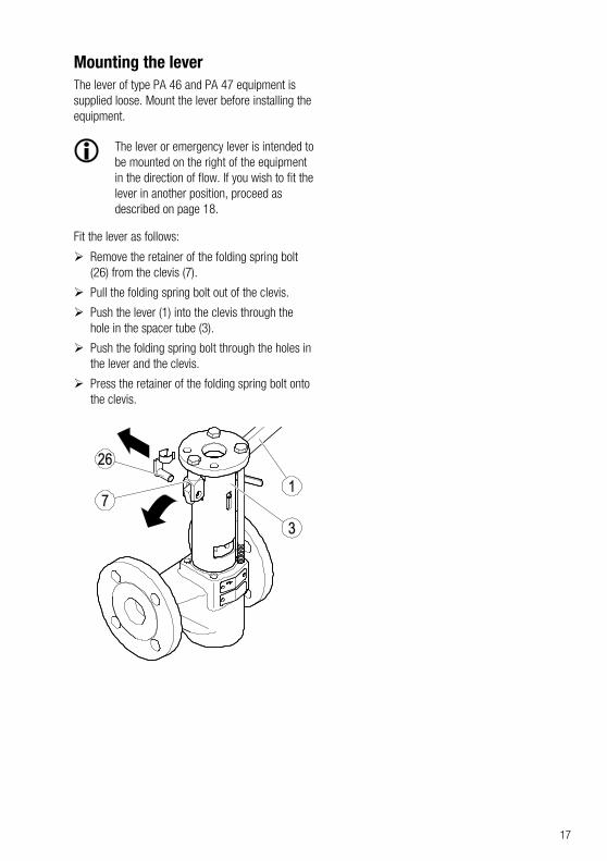
Mounting the lever The lever of type PA 46 and PA 47 equipment is supplied loose. Mount the lever before installing the equipment.
The lever or emergency lever is intended to be mounted on the right of the equipment in the direction of flow. If you wish to fit the lever in another position, proceed as described on page 18.
Fit the lever as follows:
Remove the retainer of the folding spring bolt (26) from the clevis (7).
Pull the folding spring bolt out of the clevis.
Push the lever (1) into the clevis through the hole in the spacer tube (3).
Push the folding spring bolt through the holes in the lever and the clevis.
Press the retainer of the folding spring bolt onto the clevis.
18
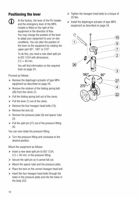
Positioning the lever
At the factory, the lever of the PA models and the emergency lever of the MPA models is fitted on the right of the equipment in the direction of flow. You may change the position of the lever to adapt your equipment to your on-site conditions. You can alter the position of the lever on the equipment by rotating the upper part 90°, 180° or 270°.
To do this, you need a new steel split pin to ISO 1234 with dimensions 2.5 × 40 mm.
You will find information on the required tools on page 24.
Proceed as follows:
Remove the diaphragm actuator of type MPA equipment as described on page 29.
Remove the retainer of the folding spring bolt (26) from the clevis (7).
Pull the folding spring bolt out of the clevis.
Pull the lever (1) out of the clevis.
Remove the four hexagon head bolts (10).
Remove the lock (2).
Remove the pressure plate (9) and spacer tube (3).
Pull the split pin (27) out of the pressure fitting (4).
You can now rotate the pressure fitting.
Turn the pressure fitting anti-clockwise to the desired position.
Mount the equipment as follows:
Insert a new steel split pin to ISO 1234, 2.5 × 40 mm, in the pressure fitting.
Secure the split pin so it cannot fall out.
Mount the spacer tube and the pressure plate.
Place the lock on the correct hexagon head bolt.
Insert the four hexagon head bolts through the holes in the pressure plate and into the holes in the body (22).
Tighten the hexagon head bolts to a torque of 20 Nm.
Install the diaphragm actuator of type MPA equipment as described on page 34.
19
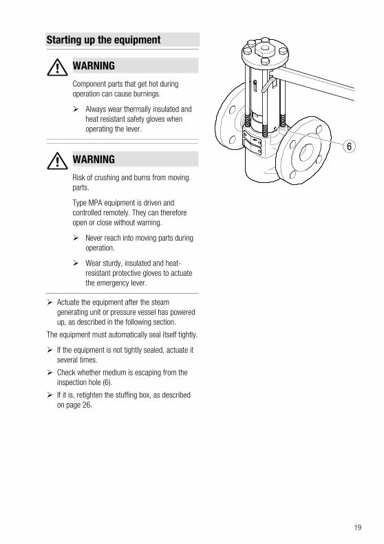
Starting up the equipment
WARNING
Component parts that get hot during operation can cause burnings.
Always wear thermally insulated and heat resistant safety gloves when operating the lever.
WARNING
Risk of crushing and burns from moving parts.
Type MPA equipment is driven and controlled remotely. They can therefore open or close without warning.
Never reach into moving parts during operation.
Wear sturdy, insulated and heat-resistant protective gloves to actuate the emergency lever.
Actuate the equipment after the steam generating unit or pressure vessel has powered up, as described in the following section.
The equipment must automatically seal itself tightly.
If the equipment is not tightly sealed, actuate it several times.
Check whether medium is escaping from the inspection hole (6).
If it is, retighten the stuffing box, as described on page 26.
20
Operating the equipment The intervals required for the boiler blowdown must be determined for each individual steam boiler and have to be stipulated by the operator.
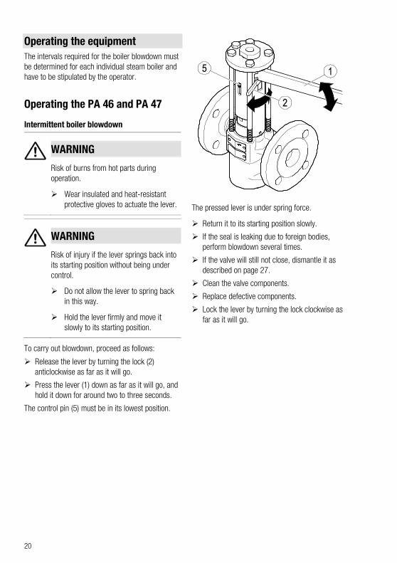
Operating the PA 46 and PA 47
Intermittent boiler blowdown
WARNING
Risk of burns from hot parts during operation.
Wear insulated and heat-resistant protective gloves to actuate the lever.
WARNING
Risk of injury if the lever springs back into its starting position without being under control.
Do not allow the lever to spring back in this way.
Hold the lever firmly and move it slowly to its starting position.
To carry out blowdown, proceed as follows:
Release the lever by turning the lock (2) anticlockwise as far as it will go.
Press the lever (1) down as far as it will go, and hold it down for around two to three seconds.
The control pin (5) must be in its lowest position.
The pressed lever is under spring force.
Return it to its starting position slowly.
If the seal is leaking due to foreign bodies, perform blowdown several times.
If the valve will still not close, dismantle it as described on page 27.
Clean the valve components.
Replace defective components.
Lock the lever by turning the lock clockwise as far as it will go.
21
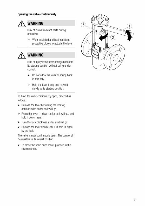
Opening the valve continuously
WARNING
Risk of burns from hot parts during operation.
Wear insulated and heat-resistant protective gloves to actuate the lever.
WARNING
Risk of injury if the lever springs back into its starting position without being under control.
Do not allow the lever to spring back in this way.
Hold the lever firmly and move it slowly to its starting position.
To have the valve continuously open, proceed as follows:
Release the lever by turning the lock (2) anticlockwise as far as it will go.
Press the lever (1) down as far as it will go, and hold it down there.
Turn the lock clockwise as far as it will go.
Release the lever slowly until it is held in place by the lock.
The valve is now continuously open. The control pin (5) must be in its lowest position.
To close the valve once more, proceed in the reverse order.
22
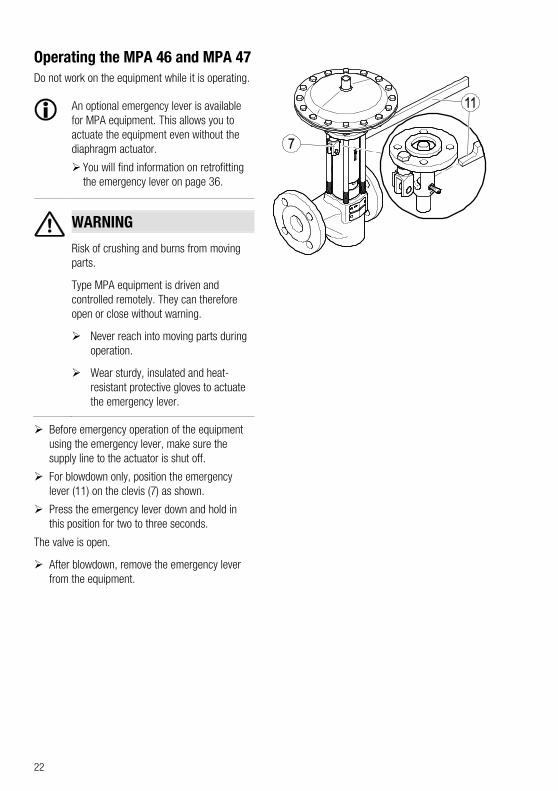
Operating the MPA 46 and MPA 47 Do not work on the equipment while it is operating.
An optional emergency lever is available for MPA equipment. This allows you to actuate the equipment even without the diaphragm actuator.
You will find information on retrofitting the emergency lever on page 36.
WARNING
Risk of crushing and burns from moving parts.
Type MPA equipment is driven and controlled remotely. They can therefore open or close without warning.
Never reach into moving parts during operation.
Wear sturdy, insulated and heat-resistant protective gloves to actuate the emergency lever.
Before emergency operation of the equipment using the emergency lever, make sure the supply line to the actuator is shut off.
For blowdown only, position the emergency lever (11) on the clevis (7) as shown.
Press the emergency lever down and hold in this position for two to three seconds.
The valve is open.
After blowdown, remove the emergency lever from the equipment.
23
After operation
DANGER
If the equipment is used in contaminated areas there is a risk of severe injuries or death caused by harmful substances in or on the equipment.
Only qualified personnel are allowed to perform work on contaminated equipment.
Always wear the protective clothing prescribed for contaminated areas when working on the equipment.
Make sure that the equipment is completely decontaminated before carrying out any service work.
Follow the pertinent instructions for handling the hazardous substances in question.
DANGER
Personnel working on pipes are exposed to safety risks and may suffer severe injuries, poisoning or even loss of life.
Make sure that no hot or hazardous fluid is in the equipment or the pipes.
Make sure that the pipes upstream and downstream of the equipment are depressurised.
Make sure that the installation is switched off and protected against unauthorised or unintended activation.
Make sure that the equipment and the pipes have cooled down to room temperatures.
Wear protective clothing that is suitable for the fluid and, if necessary, wear protective gear.
For more information on suitable protective clothing and safety gear refer to the safety data sheet of the fluid in question.
DANGER
Risk of bruises when working on the equipment during operation.
Switch off the equipment if you have to work close to any moving equipment parts.
Make sure that the equipment cannot be switched on inadvertently.
Attention! Damage to the equipment due to improper maintenance work.
Make sure that only qualified personnel performs maintenance work.
A qualified person must be acquainted with and experienced in the following:
Working on pressure equipment
Lifting loads
Assembling and disassembling the equipment
The qualified personnel must observe and follow the instructions given in this operating manual and in the applicable documents.
Removing external dirt deposits Use fresh water and a cloth to remove dirt and
contaminants from the equipment body.
24
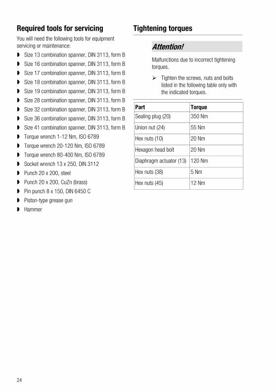
Required tools for servicing You will need the following tools for equipment servicing or maintenance:
Size 13 combination spanner, DIN 3113, form B
Size 16 combination spanner, DIN 3113, form B
Size 17 combination spanner, DIN 3113, form B
Size 18 combination spanner, DIN 3113, form B
Size 19 combination spanner, DIN 3113, form B
Size 28 combination spanner, DIN 3113, form B
Size 32 combination spanner, DIN 3113, form B
Size 36 combination spanner, DIN 3113, form B
Size 41 combination spanner, DIN 3113, form B
Torque wrench 1-12 Nm, ISO 6789
Torque wrench 20-120 Nm, ISO 6789
Torque wrench 80-400 Nm, ISO 6789
Socket wrench 13 x 250, DIN 3112
Punch 20 x 200, steel
Punch 20 x 200, CuZn (brass)
Pin punch 8 x 150, DIN 6450 C
Piston-type grease gun
Hammer
Tightening torques
Attention! Malfunctions due to incorrect tightening torques.
Tighten the screws, nuts and bolts listed in the following table only with the indicated torques.
Part Torque
Sealing plug (20) 350 Nm
Union nut (24) 55 Nm
Hex nuts (10) 20 Nm
Hexagon head bolt 20 Nm
Diaphragm actuator (13) 120 Nm
Hex nuts (38) 5 Nm
Hex nuts (45) 12 Nm
25
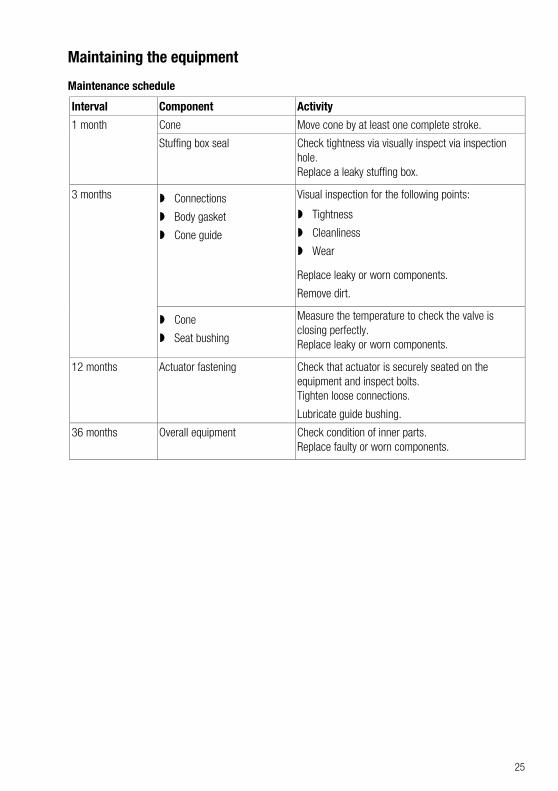
Maintaining the equipment
Maintenance schedule
Interval Component Activity
1 month Cone Move cone by at least one complete stroke.
Stuffing box seal Check tightness via visually inspect via inspection hole. Replace a leaky stuffing box.
3 months Connections
Body gasket
Cone guide
Visual inspection for the following points:
Tightness
Cleanliness
Wear
Replace leaky or worn components.
Remove dirt.
Cone
Seat bushing
Measure the temperature to check the valve is closing perfectly. Replace leaky or worn components.
12 months Actuator fastening Check that actuator is securely seated on the equipment and inspect bolts. Tighten loose connections.
Lubricate guide bushing.
36 months Overall equipment Check condition of inner parts. Replace faulty or worn components.
26
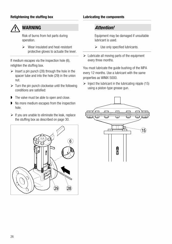
Retightening the stuffing box
WARNING
Risk of burns from hot parts during operation.
Wear insulated and heat-resistant protective gloves to actuate the lever.
If medium escapes via the inspection hole (6), retighten the stuffing box.
Insert a pin punch (28) through the hole in the spacer tube and into the hole (29) in the union nut.
Turn the pin punch clockwise until the following conditions are satisfied:
The valve must be able to open and close.
No more medium escapes from the inspection hole.
If you are unable to eliminate the leak, replace the stuffing box as described on page 30.
Lubricating the components
Attention! Equipment may be damaged if unsuitable lubricant is used.
Use only specified lubricants.
Lubricate all moving parts of the equipment every three months.
You must lubricate the guide bushing of the MPA every 12 months. Use a lubricant with the same properties as WINIX 5000.
Inject the lubricant in the lubricating nipple (15) using a piston-type grease gun.
27
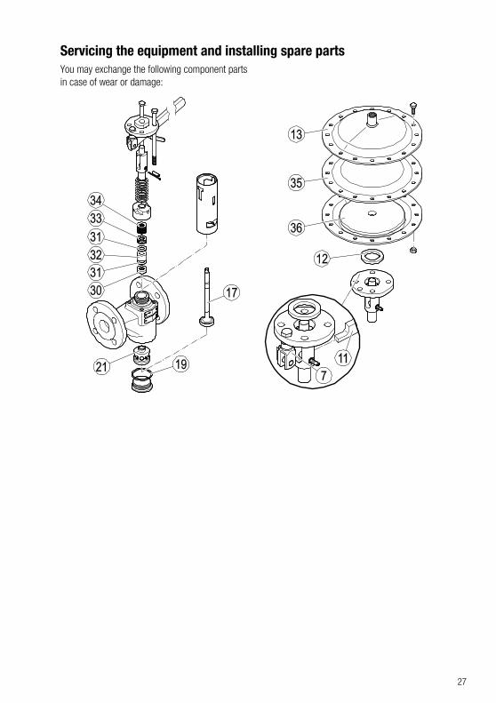
Servicing the equipment and installing spare parts You may exchange the following component parts in case of wear or damage:
28
No. Designation Stock code
PA MPA
19, 30, 31, 32, 33, 34
Stuffing box, comprising:
Gasket D 38 × 44
Gasket D 52 × 60
Base bushing
1 packing
2 wipers
Stuffing
15 disc springs
335064
17, 19, 21, 30, 31, 32, 33, 34
Cone, seat bushing and stuffing box DN 20, DN 25, DN 32
Stuffing box, comprising:
Gasket D 38 × 44
Base bushing
1 packing
2 wipers
Stuffing
15 disc springs
335063
17, 19, 21, 30, 31, 32, 33, 34
Cone, seat bushing and stuffing DN 40, DN 50
Stuffing box, comprising:
Gasket D 52 × 60
Base bushing
1 packing
2 wipers
Stuffing
15 disc springs
335065
35 Diaphragm – 335131
12, 36 Guide bushing with washer and spacer (conversion kit for diaphragm actuator of MPA 26)
– 335130
12, 13 Diaphragm actuator with spacer (retrofit kit)
– 335093
7, 11 Emergency lever, complete – 335060
– Lever extension 335302 –
29
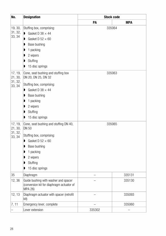
Removing the diaphragm actuator from MPA models
You can tell that a diaphragm is damaged from the following circumstances:
The valve does not open perfectly
You can hear the sound of escaping medium at the pressure relief hole on the underside of the diaphragm actuator
Medium is escaping from the pressure relief hole on the underside of the diaphragm actuator.
Replace a damaged diaphragm as follows:
Unfasten the medium connection (14) from the diaphragm actuator.
Remove the diaphragm actuator (13) from the equipment.
Removing the lever and lock from PA models
Remove the lever as follows:
Remove the retainer of the folding spring bolt (26) from the clevis (7).
Pull the folding spring bolt out of the clevis.
Remove the lever (1).
Unscrew the hexagon head bolt (10) that is securing the lock.
Remove the lock (2).
Screw the hexagon head bolt back in.
Tighten the hexagon head bolt to a torque of 20 Nm.
30
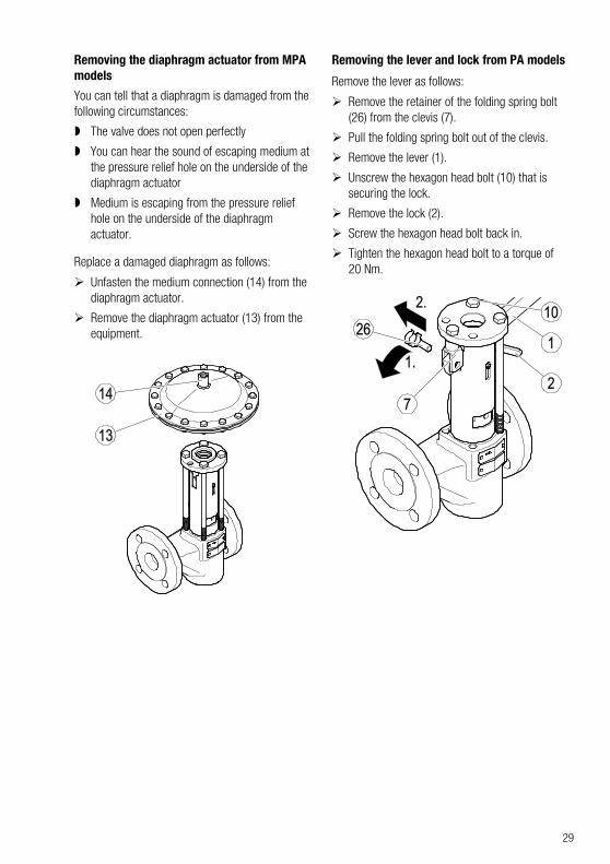
Removing the stuffing box and cone
Remove the diaphragm actuator from type MPA equipment as described on page 29.
Remove the lever from type PA equipment as described on page 29.
Remove the hexagon head bolts (10) from the pressure plate.
Remove the pressure plate (9).
Remove the spacer tube (3).
Pull the split pin (27) out of the pressure fitting and cone.
Unscrew the pressure fitting (4) from the cone using a size 28 open-end spanner.
Remove the spring (25).
Unscrew the union nut (24) from the body using a size 32 open-end spanner.
Remove the sealing plug (20) and gasket (19) from the body.
Pull the cone (17) down and out of the body.
Remove the stuffing box (23).
Replacing the stuffing box and inner parts
Remove the stuffing box and cone as described on page 30.
Replace the stuffing box with a new one.
Mount the equipment as described on page 32.
Replacing the seat bushing and cone
When replacing the seat bushing and cone, you also need to replace the stuffing box.
Remove the stuffing box and cone as described on page 30.
Using a steel punch, knock the seat bushing (21) out of the body (22) as shown.
Attention! Positioning the seat bushing incorrectly in the body can lead to malfunctions.
Rotate the seat bushing so that two facing holes are in the direction of flow of the equipment.
31
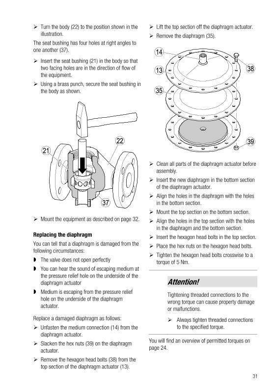
Turn the body (22) to the position shown in the illustration.
The seat bushing has four holes at right angles to one another (37).
Insert the seat bushing (21) in the body so that two facing holes are in the direction of flow of the equipment.
Using a brass punch, secure the seat bushing in the body as shown.
Mount the equipment as described on page 32.
Replacing the diaphragm
You can tell that a diaphragm is damaged from the following circumstances:
The valve does not open perfectly
You can hear the sound of escaping medium at the pressure relief hole on the underside of the diaphragm actuator
Medium is escaping from the pressure relief hole on the underside of the diaphragm actuator.
Replace a damaged diaphragm as follows:
Unfasten the medium connection (14) from the diaphragm actuator.
Slacken the hex nuts (39) on the diaphragm actuator.
Remove the hexagon head bolts (38) from the top section of the diaphragm actuator (13).
Lift the top section off the diaphragm actuator.
Remove the diaphragm (35).
Clean all parts of the diaphragm actuator before assembly.
Insert the new diaphragm in the bottom section of the diaphragm actuator.
Align the holes in the diaphragm with the holes in the bottom section.
Mount the top section on the bottom section.
Align the holes in the top section with the holes in the diaphragm and the bottom section.
Insert the hexagon head bolts in the top section.
Place the hex nuts on the hexagon head bolts.
Tighten the hexagon head bolts crosswise to a torque of 5 Nm.
Attention! Tightening threaded connections to the wrong torque can cause property damage or malfunctions.
Always tighten threaded connections to the specified torque.
You will find an overview of permitted torques on page 24.
32
Check whether medium is escaping from between the top and bottom sections of the diaphragm actuator.
If leaks are present, tighten the bolts in the diaphragm actuator crosswise to the specified torque.
If medium continues to escape, please contact the manufacturer.
Grease the guide bushing as described on page 26.
Assembling the equipment
WARNING
Hot fluid spitting out of the equipment may cause injuries and scalding.
Carry out a pressure test whenever the upper and lower body parts have been taking apart and fitted together again.
Clean all component parts before re-assembly.
Grind the cone into place using grinding compound.
The grinding compound must have the same properties as F400.
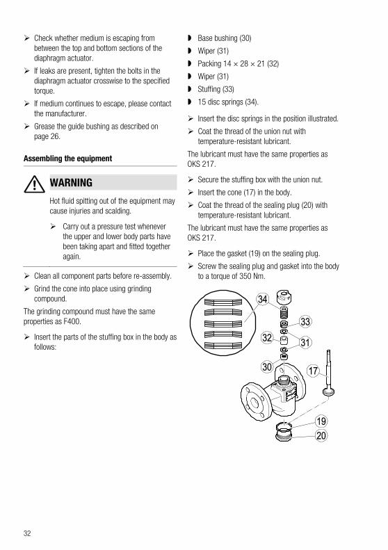
Insert the parts of the stuffing box in the body as follows:
Base bushing (30)
Wiper (31)
Packing 14 × 28 × 21 (32)
Wiper (31)
Stuffing (33)
15 disc springs (34).
Insert the disc springs in the position illustrated.
Coat the thread of the union nut with temperature-resistant lubricant.
The lubricant must have the same properties as OKS 217.
Secure the stuffing box with the union nut.
Insert the cone (17) in the body.
Coat the thread of the sealing plug (20) with temperature-resistant lubricant.
The lubricant must have the same properties as OKS 217.
Place the gasket (19) on the sealing plug.
Screw the sealing plug and gasket into the body to a torque of 350 Nm.
33
Coat the stuffing box thread with temperature-resistant lubricant.
The lubricant must have the same properties as WINIX® 2150.
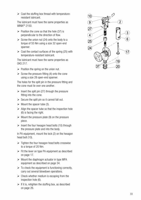
Position the cone so that the hole (37) is perpendicular to the direction of flow.
Screw the union nut (24) onto the body to a torque of 55 Nm using a size 32 open-end spanner.
Coat the contact surfaces of the spring (25) with temperature-resistant lubricant.
The lubricant must have the same properties as OKS 217.
Position the spring on the union nut.
Screw the pressure fitting (4) onto the cone using a size 28 open-end spanner.
The holes for the split pin in the pressure fitting and the cone must lie over one another.
Insert the split pin (27) through the pressure fitting into the cone.
Secure the split pin so it cannot fall out.
Mount the spacer tube (3).
Align the spacer tube so that the inspection hole (6) is facing the right.
Mount the pressure plate (9) on the pressure piece.
Insert the four hexagon head bolts (10) through the pressure plate and into the body.
In PA equipment, mount the lock (2) on the hexagon head bolt (10).
Tighten the four hexagon head bolts crosswise to a torque of 20 Nm.
Fit the lever on type PA equipment as described on page 17.
Mount the diaphragm actuator in type MPA equipment as described on page 34.
To check the equipment is functioning correctly, carry out several blowdown operations.
Check whether medium is escaping from the inspection hole (6).
If it is, retighten the stuffing box, as described on page 26.
34
Retrofitting the equipment
Mounting the diaphragm actuator
You can convert a manually operated PA to an MPA with diaphragm actuator. To do this, you require the diaphragm actuator with stock code 335093.
The diaphragm actuator contains the following components:
Diaphragm actuator
Spacer
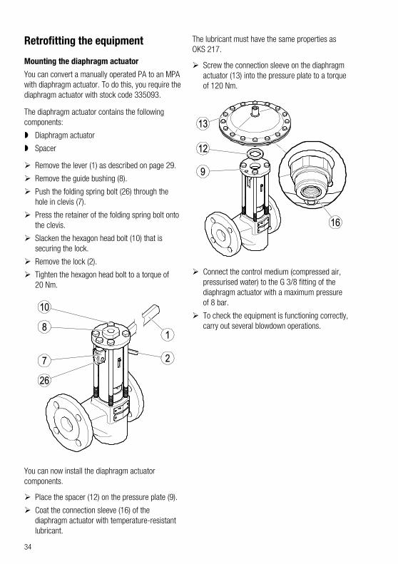
Remove the lever (1) as described on page 29.
Remove the guide bushing (8).
Push the folding spring bolt (26) through the hole in clevis (7).
Press the retainer of the folding spring bolt onto the clevis.
Slacken the hexagon head bolt (10) that is securing the lock.
Remove the lock (2).
Tighten the hexagon head bolt to a torque of 20 Nm.
You can now install the diaphragm actuator components.
Place the spacer (12) on the pressure plate (9).
Coat the connection sleeve (16) of the diaphragm actuator with temperature-resistant lubricant.
The lubricant must have the same properties as OKS 217.
Screw the connection sleeve on the diaphragm actuator (13) into the pressure plate to a torque of 120 Nm.
Connect the control medium (compressed air, pressurised water) to the G 3/8 fitting of the diaphragm actuator with a maximum pressure of 8 bar.
To check the equipment is functioning correctly, carry out several blowdown operations.
35
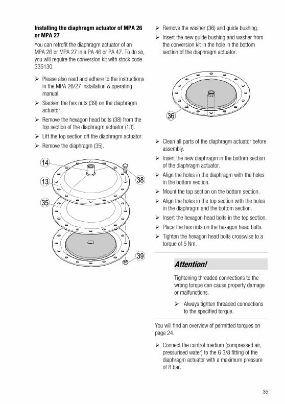
Installing the diaphragm actuator of MPA 26 or MPA 27
You can retrofit the diaphragm actuator of an MPA 26 or MPA 27 in a PA 46 or PA 47. To do so, you will require the conversion kit with stock code 335130.
Please also read and adhere to the instructions in the MPA 26/27 installation & operating manual.
Slacken the hex nuts (39) on the diaphragm actuator.
Remove the hexagon head bolts (38) from the top section of the diaphragm actuator (13).
Lift the top section off the diaphragm actuator.
Remove the diaphragm (35).
Remove the washer (36) and guide bushing.
Insert the new guide bushing and washer from the conversion kit in the hole in the bottom section of the diaphragm actuator.
Clean all parts of the diaphragm actuator before assembly.
Insert the new diaphragm in the bottom section of the diaphragm actuator.
Align the holes in the diaphragm with the holes in the bottom section.
Mount the top section on the bottom section.
Align the holes in the top section with the holes in the diaphragm and the bottom section.
Insert the hexagon head bolts in the top section.
Place the hex nuts on the hexagon head bolts.
Tighten the hexagon head bolts crosswise to a torque of 5 Nm.
Attention! Tightening threaded connections to the wrong torque can cause property damage or malfunctions.
Always tighten threaded connections to the specified torque.
You will find an overview of permitted torques on page 24.
Connect the control medium (compressed air, pressurised water) to the G 3/8 fitting of the diaphragm actuator with a maximum pressure of 8 bar.
36
Check whether medium is escaping from between the top and bottom sections of the diaphragm actuator.
If leaks are present, tighten the bolts in the diaphragm actuator crosswise to the specified torque.
If medium continues to escape, please contact the manufacturer.
Grease the guide bushing as described on page 26.
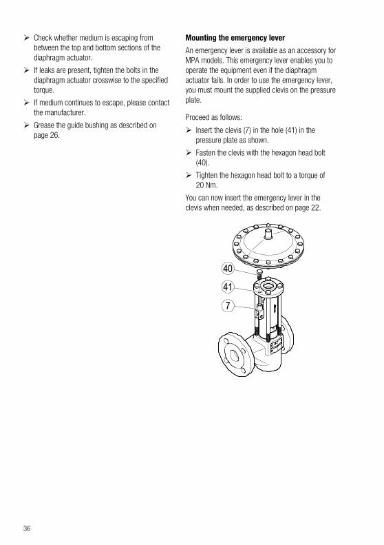
Mounting the emergency lever
An emergency lever is available as an accessory for MPA models. This emergency lever enables you to operate the equipment even if the diaphragm actuator fails. In order to use the emergency lever, you must mount the supplied clevis on the pressure plate.
Proceed as follows:
Insert the clevis (7) in the hole (41) in the pressure plate as shown.
Fasten the clevis with the hexagon head bolt (40).
Tighten the hexagon head bolt to a torque of 20 Nm.
You can now insert the emergency lever in the clevis when needed, as described on page 22.
37
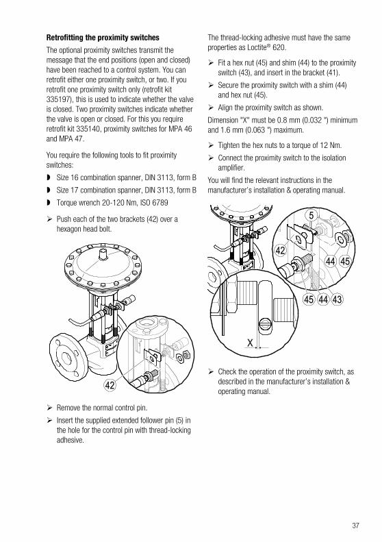
Retrofitting the proximity switches
The optional proximity switches transmit the message that the end positions (open and closed) have been reached to a control system. You can retrofit either one proximity switch, or two. If you retrofit one proximity switch only (retrofit kit 335197), this is used to indicate whether the valve is closed. Two proximity switches indicate whether the valve is open or closed. For this you require retrofit kit 335140, proximity switches for MPA 46 and MPA 47.
You require the following tools to fit proximity switches:
Size 16 combination spanner, DIN 3113, form B
Size 17 combination spanner, DIN 3113, form B
Torque wrench 20-120 Nm, ISO 6789
Push each of the two brackets (42) over a hexagon head bolt.
Remove the normal control pin.
Insert the supplied extended follower pin (5) in the hole for the control pin with thread-locking adhesive.
The thread-locking adhesive must have the same properties as Loctite® 620.
Fit a hex nut (45) and shim (44) to the proximity switch (43), and insert in the bracket (41).
Secure the proximity switch with a shim (44) and hex nut (45).
Align the proximity switch as shown.
Dimension "X" must be 0.8 mm (0.032 ") minimum and 1.6 mm (0.063 ") maximum.
Tighten the hex nuts to a torque of 12 Nm.
Connect the proximity switch to the isolation amplifier.
You will find the relevant instructions in the manufacturer’s installation & operating manual.
Check the operation of the proximity switch, as described in the manufacturer’s installation & operating manual.
38
Troubleshooting Problem Cause Remedy
Fluid escapes (equipment is leaking).
The equipment or the body is damaged.
Replace the equipment with a new one.
Fluid escapes (equipment is leaking).
A gasket is damaged. Replace the gasket with a new one.
Clean gasket seating surfaces.
Fluid escapes (equipment is leaking).
The connections are not tight. Provide the connections with leakproof seals.
Fluid escapes (equipment is leaking).
The stuffing box packing has not been tightened enough.
Tighten the stuffing-box packing hand tight.
Make sure that the stuffing box packing does not impair the movement of the internals.
Fluid escapes (equipment is leaking).
The stuffing-box packing is damaged.
Replace the stuffing-box packing.
The equipment does not close fully.
The equipment contains dirt, deposits or foreign bodies.
Open and close the equipment several times quickly.
Clean all inner parts.
Replace damaged inner parts.
The cone moves jerkily or with difficulty, or is jammed.
Malfunctioning actuator or accessory.
Follow the instructions in the actuator or accessory installation & operating manual.
Control system malfunction. Follow the instructions in the control system installation & operating manual.
The stuffing box hinders the stroke of the cone.
Slightly slacken the union nut.
If the stuffing box continues to hinder the cone stroke, replace the stuffing box.
If faults occur that are not listed above or cannot be corrected, please contact our Technical Service or authorized agency in your country.
39
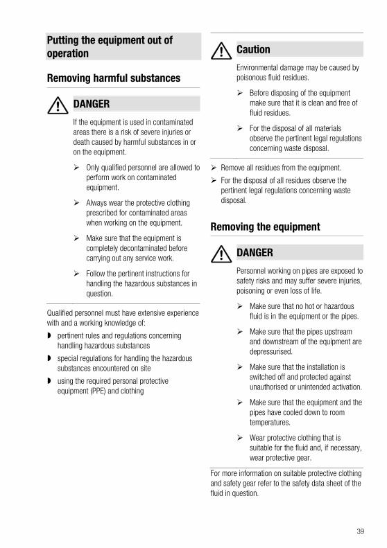
Putting the equipment out of operation
Removing harmful substances
DANGER
If the equipment is used in contaminated areas there is a risk of severe injuries or death caused by harmful substances in or on the equipment.
Only qualified personnel are allowed to perform work on contaminated equipment.
Always wear the protective clothing prescribed for contaminated areas when working on the equipment.
Make sure that the equipment is completely decontaminated before carrying out any service work.
Follow the pertinent instructions for handling the hazardous substances in question.
Qualified personnel must have extensive experience with and a working knowledge of:
pertinent rules and regulations concerning handling hazardous substances
special regulations for handling the hazardous substances encountered on site
using the required personal protective equipment (PPE) and clothing
Caution
Environmental damage may be caused by poisonous fluid residues.
Before disposing of the equipment make sure that it is clean and free of fluid residues.
For the disposal of all materials observe the pertinent legal regulations concerning waste disposal.
Remove all residues from the equipment.
For the disposal of all residues observe the pertinent legal regulations concerning waste disposal.
Removing the equipment
DANGER
Personnel working on pipes are exposed to safety risks and may suffer severe injuries, poisoning or even loss of life.
Make sure that no hot or hazardous fluid is in the equipment or the pipes.
Make sure that the pipes upstream and downstream of the equipment are depressurised.
Make sure that the installation is switched off and protected against unauthorised or unintended activation.
Make sure that the equipment and the pipes have cooled down to room temperatures.
Wear protective clothing that is suitable for the fluid and, if necessary, wear protective gear.
For more information on suitable protective clothing and safety gear refer to the safety data sheet of the fluid in question.
40
CAUTION
Risk of injuries if the equipment falls down.
When removing the equipment make sure the it is safely held in place and cannot fall down.
Suitable measures are for instance:
Equipment that is not too heavy may be supported by a second person.
For heavy equipment use suitable lifting equipment of sufficient strength.
Detach the end connections of the equipment from the pipes.
Put the equipment onto a suitable base.
Store the equipment as described on page 13.
Re-using equipment after storage Observe the following instructions if you want to remove the equipment and use it again somewhere else:
Make sure that the equipment is free of any fluid residues.
Make sure that all connections are in good condition and leak-free.
If necessary re-work welded connections in order to ensure that they are in good working condition.
Use the equipment only for its intended purpose and the service conditions for which it was specified.
41
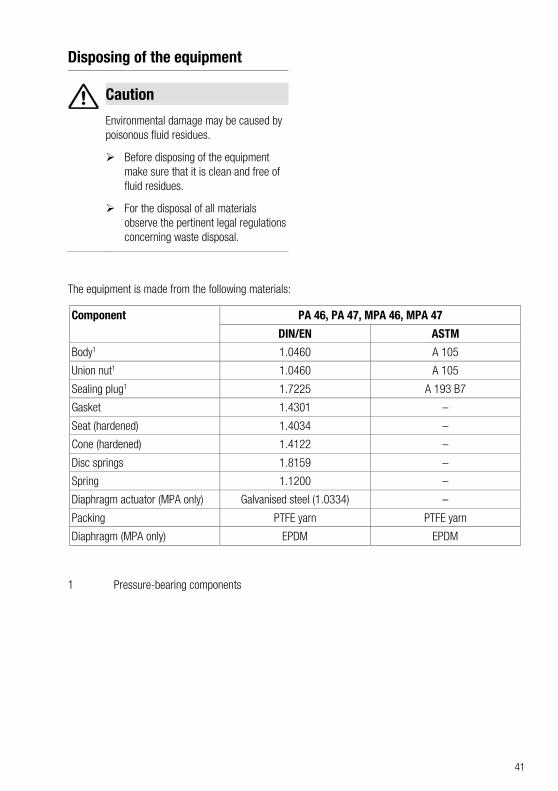
Disposing of the equipment
Caution
Environmental damage may be caused by poisonous fluid residues.
Before disposing of the equipment make sure that it is clean and free of fluid residues.
For the disposal of all materials observe the pertinent legal regulations concerning waste disposal.
The equipment is made from the following materials:
Component PA 46, PA 47, MPA 46, MPA 47
DIN/EN ASTM
Body1 1.0460 A 105
Union nut1 1.0460 A 105
Sealing plug1 1.7225 A 193 B7
Gasket 1.4301 –
Seat (hardened) 1.4034 –
Cone (hardened) 1.4122 –
Disc springs 1.8159 –
Spring 1.1200 –
Diaphragm actuator (MPA only) Galvanised steel (1.0334) –
Packing PTFE yarn PTFE yarn
Diaphragm (MPA only) EPDM EPDM
1 Pressure-bearing components
42
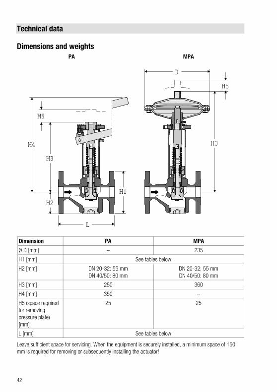
Technical data
Dimensions and weights PA MPA
Dimension PA MPA
Ø D [mm] – 235
H1 [mm] See tables below
H2 [mm] DN 20-32: 55 mm DN 40/50: 80 mm
DN 20-32: 55 mm DN 40/50: 80 mm
H3 [mm] 250 360
H4 [mm] 350 –
H5 (space required for removing pressure plate) [mm]
25 25
L [mm] See tables below
Leave sufficient space for servicing. When the equipment is securely installed, a minimum space of 150 mm is required for removing or subsequently installing the actuator!
43
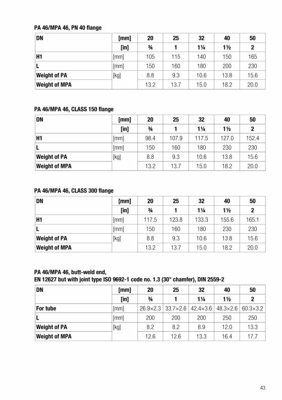
PA 46/MPA 46, PN 40 flange
DN [mm] 20 25 32 40 50
[in] ¾ 1 1¼ 1½ 2
H1 [mm] 105 115 140 150 165
L [mm] 150 160 180 200 230
Weight of PA [kg] 8.8 9.3 10.6 13.8 15.6
Weight of MPA 13.2 13.7 15.0 18.2 20.0
PA 46/MPA 46, CLASS 150 flange
DN [mm] 20 25 32 40 50
[in] ¾ 1 1¼ 1½ 2
H1 [mm] 98.4 107.9 117.5 127.0 152.4
L [mm] 150 160 180 230 230
Weight of PA [kg] 8.8 9.3 10.6 13.8 15.6
Weight of MPA 13.2 13.7 15.0 18.2 20.0
PA 46/MPA 46, CLASS 300 flange
DN [mm] 20 25 32 40 50
[in] ¾ 1 1¼ 1½ 2
H1 [mm] 117.5 123.8 133.3 155.6 165.1
L [mm] 150 160 180 230 230
Weight of PA [kg] 8.8 9.3 10.6 13.8 15.6
Weight of MPA 13.2 13.7 15.0 18.2 20.0
PA 46/MPA 46, butt-weld end, EN 12627 but with joint type ISO 9692-1 code no. 1.3 (30° chamfer), DIN 2559-2
DN [mm] 20 25 32 40 50
[in] ¾ 1 1¼ 1½ 2
For tube [mm] 26.9×2.3 33.7×2.6 42.4×3.6 48.3×2.6 60.3×3.2
L [mm] 200 200 200 250 250
Weight of PA [kg] 8.2 8.2 8.9 12.0 13.3
Weight of MPA 12.6 12.6 13.3 16.4 17.7
44
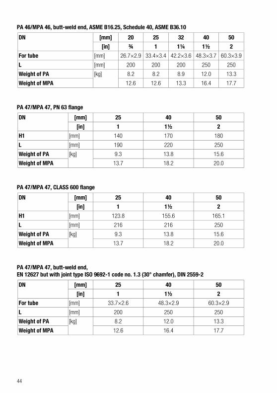
PA 46/MPA 46, butt-weld end, ASME B16.25, Schedule 40, ASME B36.10
DN [mm] 20 25 32 40 50
[in] ¾ 1 1¼ 1½ 2
For tube [mm] 26.7×2.9 33.4×3.4 42.2×3.6 48.3×3.7 60.3×3.9
L [mm] 200 200 200 250 250
Weight of PA [kg] 8.2 8.2 8.9 12.0 13.3
Weight of MPA 12.6 12.6 13.3 16.4 17.7
PA 47/MPA 47, PN 63 flange
DN [mm] 25 40 50
[in] 1 1½ 2
H1 [mm] 140 170 180
L [mm] 190 220 250
Weight of PA [kg] 9.3 13.8 15.6
Weight of MPA 13.7 18.2 20.0
PA 47/MPA 47, CLASS 600 flange
DN [mm] 25 40 50
[in] 1 1½ 2
H1 [mm] 123.8 155.6 165.1
L [mm] 216 216 250
Weight of PA [kg] 9.3 13.8 15.6
Weight of MPA 13.7 18.2 20.0
PA 47/MPA 47, butt-weld end, EN 12627 but with joint type ISO 9692-1 code no. 1.3 (30° chamfer), DIN 2559-2
DN [mm] 25 40 50
[in] 1 1½ 2
For tube [mm] 33.7×2.6 48.3×2.9 60.3×2.9
L [mm] 200 250 250
Weight of PA [kg] 8.2 12.0 13.3
Weight of MPA 12.6 16.4 17.7
45
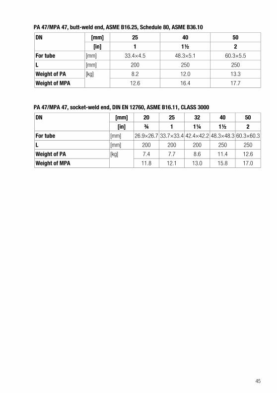
PA 47/MPA 47, butt-weld end, ASME B16.25, Schedule 80, ASME B36.10
DN [mm] 25 40 50
[in] 1 1½ 2
For tube [mm] 33.4×4.5 48.3×5.1 60.3×5.5
L [mm] 200 250 250
Weight of PA [kg] 8.2 12.0 13.3
Weight of MPA 12.6 16.4 17.7
PA 47/MPA 47, socket-weld end, DIN EN 12760, ASME B16.11, CLASS 3000
DN [mm] 20 25 32 40 50
[in] ¾ 1 1¼ 1½ 2
For tube [mm] 26.9×26.7 33.7×33.4 42.4×42.2 48.3×48.3 60.3×60.3
L [mm] 200 200 200 250 250
Weight of PA [kg] 7.4 7.7 8.6 11.4 12.6
Weight of MPA 11.8 12.1 13.0 15.8 17.0
46
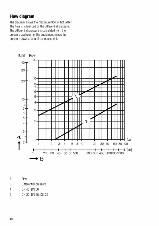
Flow diagram The diagram shows the maximum flow of hot water. The flow is influenced by the differential pressure. The differential pressure is calculated from the pressure upstream of the equipment minus the pressure downstream of the equipment.
A Flow
B Differential pressure
1 DN 40, DN 50
2 DN 20, DN 25, DN 32
47
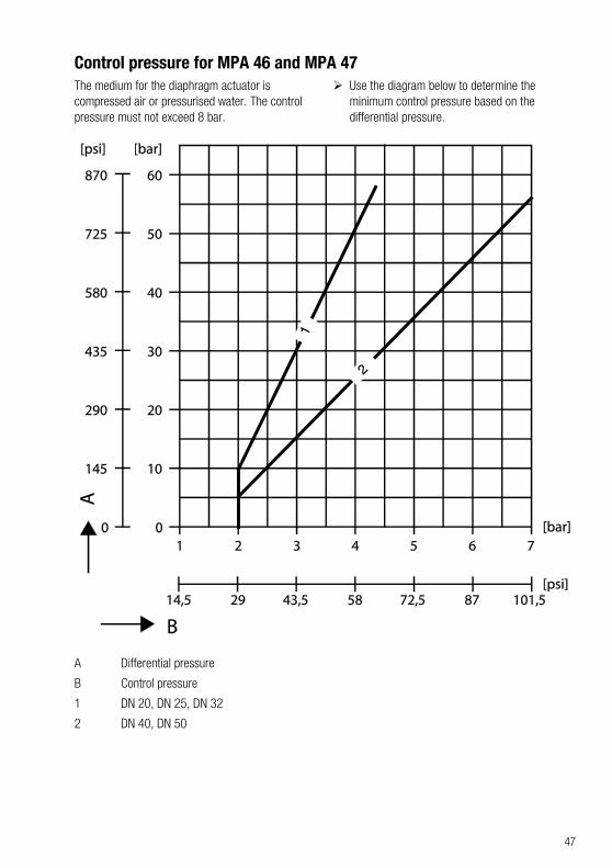
Control pressure for MPA 46 and MPA 47 The medium for the diaphragm actuator is compressed air or pressurised water. The control pressure must not exceed 8 bar.
Use the diagram below to determine the minimum control pressure based on the differential pressure.
A Differential pressure
B Control pressure
1 DN 20, DN 25, DN 32
2 DN 40, DN 50
48
Pressure & temperature ratings
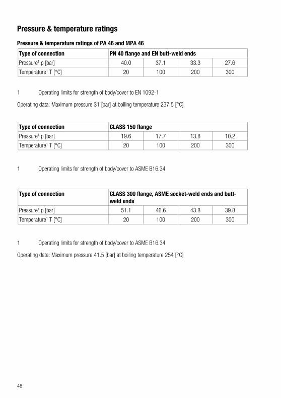
Pressure & temperature ratings of PA 46 and MPA 46
Type of connection PN 40 flange and EN butt-weld ends
Pressure1 p [bar] 40.0 37.1 33.3 27.6
Temperature1 T [°C] 20 100 200 300
1 Operating limits for strength of body/cover to EN 1092-1
Operating data: Maximum pressure 31 [bar] at boiling temperature 237.5 [°C]
Type of connection CLASS 150 flange
Pressure1 p [bar] 19.6 17.7 13.8 10.2
Temperature1 T [°C] 20 100 200 300
1 Operating limits for strength of body/cover to ASME B16.34
Type of connection CLASS 300 flange, ASME socket-weld ends and butt-weld ends
Pressure1 p [bar] 51.1 46.6 43.8 39.8
Temperature1 T [°C] 20 100 200 300
1 Operating limits for strength of body/cover to ASME B16.34
Operating data: Maximum pressure 41.5 [bar] at boiling temperature 254 [°C]
49
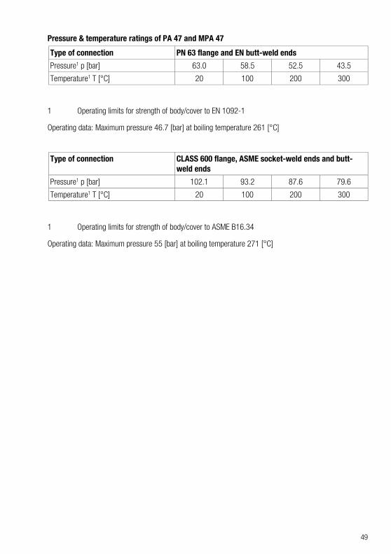
Pressure & temperature ratings of PA 47 and MPA 47
Type of connection PN 63 flange and EN butt-weld ends
Pressure1 p [bar] 63.0 58.5 52.5 43.5
Temperature1 T [°C] 20 100 200 300
1 Operating limits for strength of body/cover to EN 1092-1
Operating data: Maximum pressure 46.7 [bar] at boiling temperature 261 [°C]
Type of connection CLASS 600 flange, ASME socket-weld ends and butt-weld ends
Pressure1 p [bar] 102.1 93.2 87.6 79.6
Temperature1 T [°C] 20 100 200 300
1 Operating limits for strength of body/cover to ASME B16.34
Operating data: Maximum pressure 55 [bar] at boiling temperature 271 [°C]
50
Manufacturer's declaration For more information on the Conformity Assessment according to European rules refer to our Declaration of Conformity or our Declaration by Manufacturer.
To download the current Declaration of Conformity or Declaration by Manufacturer go to www.gestra.com/documents or contact:
GESTRA AG Münchener Straße 77 28215 Bremen Germany Telefon +49 421 3503-0 Telefax +49 421 3503-393 E-Mail [email protected] Web www.gestra.de
This declaration is no longer valid if modifications are made to the equipment without consultation with us.

51
52
Agencies all over the world: www.gestra.de
GESTRA AG
Münchener Straße 77 28215 Bremen Germany
Telefon +49 421 3503-0 Telefax +49 421 3503-393 E-Mail [email protected] Web www.gestra.de
818447-02/03-2018_Kx_mm (808565-03) © GESTRA AG Bremen Printed in Germany


![PA Web Portal Final.ppt - FirstEnergy...Microsoft PowerPoint - PA Web Portal Final.ppt [Compatibility Mode] Author: 48497 Created Date: 10/31/2016 4:00:47 PM](https://img.pdfslide.us/doc/110x75/5f7433cbb6926c027b3bd9e5/pa-web-portal-finalppt-firstenergy-microsoft-powerpoint-pa-web-portal-finalppt.jpg)