Embed Size (px)
Citation preview
Range Scrap (Firing Point) StudyCharacterization Strategy Report
February 2000
Prepared for
U.S. Army Environmental CenterAberdeen Proving Ground, Maryland
RANGE SCRAP (FIRING POINT) STUDYCHARACTERIZATION STRATEGY REPORT
U.S. Army Environmental CenterAberdeen Proving Ground, Maryland
February 2000

This page intentionally left blank.
F9909241.MW97 iii February 2000
TABLE OF CONTENTS
Page
LIST OF FIGURES ........................................................................................................................ ixLIST OF TABLES.......................................................................................................................... xi ACRONYMS ............................................................................................................................... xv EXECUTIVE SUMMARY ......................................................................................................... xvii 1.0 INTRODUCTION ........................................................................................................... 1-1
1.1 Background .......................................................................................................... 1-11.2 Project Requirements ........................................................................................... 1-31.3 Organization of Report......................................................................................... 1-4
2.0 PROJECT DQOs ............................................................................................................. 2-12.1 Problem Statement ............................................................................................... 2-22.2 Identify the Decision............................................................................................ 2-22.3 Identify Inputs to the Decision............................................................................. 2-6
2.3.1 Initial Screening....................................................................................... 2-62.3.2 Identifying Waste Streams for Characterization...................................... 2-7
2.4 Define Study Boundaries ..................................................................................... 2-82.5 Develop Decision Rules....................................................................................... 2-82.6 Specify Limits to Decision Errors...................................................................... 2-252.7 Optimize Design................................................................................................. 2-25
2.7.1 General Characterization Scheme .......................................................... 2-262.7.2 Characterization Approach for Specific Waste Streams........................ 2-28
3.0 GENERAL SAMPLING AND ANALYTICAL PROCEDURES.................................. 3-13.1 Characterization Scheme...................................................................................... 3-13.2 Sample Collection Procedures ............................................................................. 3-2
3.2.1 Sample Collection.................................................................................... 3-23.2.2 Field QA/QC Samples ............................................................................. 3-43.2.3 Sample Labeling and Handling................................................................ 3-53.2.4 Sample and Shipping Containers ............................................................. 3-53.2.5 Sample Preservation and Storage............................................................. 3-63.2.6 Sample Seals ............................................................................................ 3-63.2.7 Chain-of-Custody Record ........................................................................ 3-63.2.8 Field Logbooks/Records .......................................................................... 3-7
3.3 Sample Preparation.............................................................................................. 3-73.3.1 Specification............................................................................................. 3-83.3.2 Sample Preparation Procedure............................................................... 3-113.3.3 Quality Assurance/Quality Control Samples ......................................... 3-143.3.4 Sample Homogenization........................................................................ 3-173.3.5 Sample and Shipping Containers ........................................................... 3-173.3.6 Sample Labeling..................................................................................... 3-183.3.7 Sample Seals .......................................................................................... 3-18
F9909241.MW97 iv February 2000
TABLE OF CONTENTS (Continued)
Page
3.3.8 Sample COC and Analytical Request .................................................... 3-183.3.9 Sample Preparation Documentation....................................................... 3-193.3.10 Equipment/Tools Decontamination....................................................... 3-19
3.4 Sample Analysis................................................................................................. 3-203.4.1 Analytical Methods/Procedures ............................................................. 3-203.4.2 Laboratory DQO Goals .......................................................................... 3-213.4.3 Sample Custody and Holding Times ..................................................... 3-233.4.4 Internal QC Checks................................................................................ 3-24
4.0 WASTE STREAM-SPECIFIC SAMPLING PROTOCOLS .......................................... 4-14.1 Fired 12 Gauge Shotgun Cartridge Cases............................................................ 4-4
4.1.1 Overview.................................................................................................. 4-44.1.2 Characterization Rationale ....................................................................... 4-54.1.3 Sampling Protocol.................................................................................... 4-7
4.2 Fired 5.56mm Brass Cartridge Cases................................................................... 4-84.2.1 Overview.................................................................................................. 4-84.2.2 Characterization Rationale ....................................................................... 4-84.2.3 Sampling Protocol.................................................................................. 4-10
4.3 Fired .22 Caliber Brass Cartridge Cases ............................................................ 4-114.3.1 Overview................................................................................................ 4-114.3.2 Characterization Rationale ..................................................................... 4-124.3.3 Sampling Protocol.................................................................................. 4-14
4.4 Fired .30 Caliber Brass Cartridge Cases ............................................................ 4-144.4.1 Overview................................................................................................ 4-144.4.2 Characterization Rationale ..................................................................... 4-154.4.3 Sampling Protocol.................................................................................. 4-17
4.5 Fired 9mm Cartridge Cases ............................................................................... 4-174.5.1 Overview................................................................................................ 4-174.5.2 Characterization Rationale ..................................................................... 4-184.5.3 Sampling Protocol.................................................................................. 4-20
4.6 Fired .45 Caliber Brass Cartridge Cases ............................................................ 4-204.6.1 Overview................................................................................................ 4-204.6.2 Characterization Rationale ..................................................................... 4-214.6.3 Sampling Protocol.................................................................................. 4-23
4.7 Fired 7.62mm Brass Cartridge Cases................................................................. 4-234.7.1 Overview................................................................................................ 4-234.7.2 Characterization Rationale ..................................................................... 4-234.7.3 Sampling Protocol.................................................................................. 4-27
4.8 Fired .50 Caliber Cartridge Cases...................................................................... 4-274.8.1 Overview................................................................................................ 4-274.8.2 Characterization Rationale ..................................................................... 4-284.8.3 Sampling Protocol.................................................................................. 4-30
F9909241.MW97 v February 2000
TABLE OF CONTENTS (Continued)
Page
4.9 Fired 40mm Cartridge Cases ............................................................................. 4-314.9.1 Overview................................................................................................ 4-314.9.2 Characterization Rationale ..................................................................... 4-324.9.3 Sampling Protocol.................................................................................. 4-35
4.10 M201A1 Grenade Fuze ...................................................................................... 4-354.10.1 Overview................................................................................................ 4-354.10.2 Characterization Rationale ..................................................................... 4-354.10.3 Sampling Protocol.................................................................................. 4-38
4.11 M227 Grenade Fuzes ......................................................................................... 4-384.11.1 Overview................................................................................................ 4-384.11.2 Characterization Rationale ..................................................................... 4-384.11.3 Sampling Protocol.................................................................................. 4-39
4.12 AN-M8 HC Smoke Grenades ............................................................................ 4-404.12.1 Overview................................................................................................ 4-404.12.2 Characterization Rationale ..................................................................... 4-414.12.3 Sampling Protocol.................................................................................. 4-42
4.13 M48 Red Smoke Grenades ................................................................................ 4-424.13.1 Overview................................................................................................ 4-424.13.2 Characterization Rationale ..................................................................... 4-434.13.3 Sampling Protocol.................................................................................. 4-44
4.14 M18 Red Smoke Grenade.................................................................................. 4-444.14.1 Overview................................................................................................ 4-444.14.2 Characterization Rationale ..................................................................... 4-454.14.3 Sampling Protocol.................................................................................. 4-46
4.15 Fired 14.5mm Aluminum Alloy Training Cartridge Cases ............................... 4-474.15.1 Overview................................................................................................ 4-474.15.2 Characterization Rationale ..................................................................... 4-474.15.3 Sampling Protocol.................................................................................. 4-49
4.16 Fired 25mm Cartridge Case ............................................................................... 4-494.16.1 Overview................................................................................................ 4-494.16.2 Characterization Rationale ..................................................................... 4-504.16.3 Sampling Protocol.................................................................................. 4-53
4.17 Fired 30mm Aluminum Alloy Cartridge Cases ................................................. 4-534.17.1 Overview................................................................................................ 4-534.17.2 Characterization Rationale ..................................................................... 4-544.17.3 Sampling Protocol.................................................................................. 4-56
4.18 Fired 75 to 165mm Cartridge Cases .................................................................. 4-564.18.1 Overview................................................................................................ 4-564.18.2 Characterization Rationale ..................................................................... 4-574.18.3 Sampling Protocol.................................................................................. 4-59
4.19 M18 Green Smoke Grenades ............................................................................. 4-594.19.1 Overview................................................................................................ 4-59
F9909241.MW97 vi February 2000
TABLE OF CONTENTS (Continued)
Page
4.19.2 Characterization Rationale ..................................................................... 4-604.19.3 Sampling Protocol.................................................................................. 4-61
4.20 M18 Yellow Smoke Grenades ........................................................................... 4-624.20.1 Overview................................................................................................ 4-624.20.2 Characterization Rationale ..................................................................... 4-614.20.3 Sampling Protocol.................................................................................. 4-64
4.21 Fired M82 Percussion Primer Brass Cartridge Cases ........................................ 4-644.21.1 Overview................................................................................................ 4-644.21.2 Characterization Rationale ..................................................................... 4-654.21.3 Sampling Protocol.................................................................................. 4-66
4.22 M60 Firing Device............................................................................................. 4-674.22.1 Overview................................................................................................ 4-674.22.2 Characterization Rationale ..................................................................... 4-684.22.3 Sampling Protocol.................................................................................. 4-69
4.23 M6 Electric Blasting Cap................................................................................... 4-694.23.1 Overview................................................................................................ 4-694.23.2 Characterization Rationale ..................................................................... 4-694.23.3 Sampling Protocol.................................................................................. 4-71
4.24 M7 Nonelectric Blasting Cap............................................................................. 4-714.24.1 Overview................................................................................................ 4-714.24.2 Characterization Rationale ..................................................................... 4-724.24.3 Sampling Protocol.................................................................................. 4-73
4.25 M5 Steel Demolition Firing Devices ................................................................. 4-744.25.1 Overview................................................................................................ 4-744.25.2 Characterization Rationale ..................................................................... 4-744.24.3 Sampling Protocol.................................................................................. 4-76
4.26 M7A3 CS Riot Control Hand Grenade.............................................................. 4-764.26.1 Overview................................................................................................ 4-764.26.2 Characterization Rationale..................................................................... 4-774.26.3 Sampling Protocol.................................................................................. 4-78
4.27 ABC-M5 HC Smoke Pot ................................................................................... 4-784.27.1 Overview................................................................................................ 4-784.27.2 Characterization Rationale ..................................................................... 4-784.27.3 Sampling Protocol.................................................................................. 4-79
4.28 TH3 AN-M14 Incendiary Hand Grenade .......................................................... 4-804.28.1 Overview................................................................................................ 4-804.28.2 Characterization Rationale ..................................................................... 4-804.28.3 Sampling Protocol.................................................................................. 4-82
4.29 M18 Violet Smoke Hand Grenade..................................................................... 4-824.29.1 Overview................................................................................................ 4-824.29.2 Characterization Rationale ..................................................................... 4-834.29.3 Sampling Protocol.................................................................................. 4-83
F9909241.MW97 vii February 2000
TABLE OF CONTENTS (Continued)
Page
4.30 Floating Smoke Pot Type HC M4A2................................................................. 4-844.30.1 Overview................................................................................................ 4-844.30.2 Characterization Rationale ..................................................................... 4-844.30.3 Sampling Protocol.................................................................................. 4-86
4.31 M11 Nonelectric Blasting Cap (Primary Detonator) ......................................... 4-864.31.1 Overview................................................................................................ 4-864.31.2 Characterization Rationale ..................................................................... 4-874.31.3 Sampling Protocol.................................................................................. 4-88
4.32 M12 and M13 Nonelectric Blasting Cap (Donor Detonator) ............................ 4-884.32.1 Overview................................................................................................ 4-884.32.2 Characterization Rationale ..................................................................... 4-894.32.3 Sampling Protocol.................................................................................. 4-91
4.33 M14 Nonelectric Blasting Cap (Time Fuse)...................................................... 4-914.33.1 Overview................................................................................................ 4-914.33.2 Characterization Rationale ..................................................................... 4-924.33.3 Sampling Protocol.................................................................................. 4-93
4.34 M15 Nonelectric Delay Blasting Cap ................................................................ 4-934.34.1 Overview................................................................................................ 4-934.34.2 Characterization Rationale ..................................................................... 4-944.34.3 Sampling Protocol.................................................................................. 4-95
4.35 Personal Distress Flare Kit................................................................................. 4-954.35.1 Overview................................................................................................ 4-954.35.2 Characterization Rationale ..................................................................... 4-964.35.3 Sampling Protocol.................................................................................. 4-97
4.36 HC M1 155mm Smoke Canister........................................................................ 4-974.36.1 Overview................................................................................................ 4-974.36.2 Characterization Rationale ..................................................................... 4-974.36.3 Sampling Protocol.................................................................................. 4-98
4.37 Fired 10 Gauge Shotgun Cartridge Cases.......................................................... 4-994.37.1 Overview................................................................................................ 4-994.37.2 Characterization Rationale ..................................................................... 4-994.37.3 Sampling Protocol................................................................................ 4-101
4.38 M81 Firing Device........................................................................................... 4-1014.38.1 Overview.............................................................................................. 4-1014.38.2 Characterization Rationale ................................................................... 4-1024.38.3 Sampling Protocol................................................................................ 4-103
4.39 Fired 20mm Cartridge Cases ........................................................................... 4-1044.39.1 Overview.............................................................................................. 4-1044.39.2 Characterization Rationale ................................................................... 4-1044.39.3 Sampling Protocol................................................................................ 4-106
F9909241.MW97 viii February 2000
TABLE OF CONTENTS (Continued)
Page
4.40 Fired 25.4mm Decoy Cartridge Cases ............................................................. 4-1064.40.1 Overview.............................................................................................. 4-1064.40.2 Characterization Rationale ................................................................... 4-1074.40.3 Sampling Protocol................................................................................ 4-109
5.0 DATA INTERPRETATION AND REPORTING.......................................................... 5-15.1 Data Reduction, Validation, and Reporting......................................................... 5-1
5.1.1 Data Reduction......................................................................................... 5-15.1.2 Calculation of Data Quality Indicators .................................................... 5-15.1.3 Data Review............................................................................................. 5-25.1.4 Data Validation........................................................................................ 5-35.1.5 Data Reporting......................................................................................... 5-35.1.6 Laboratory Turnaround Time................................................................... 5-3
5.2 Project DQOs....................................................................................................... 5-45.2.1 Hazardous Waste Determination............................................................. 5-45.2.2 Identification of UHCs............................................................................. 5-55.2.3 Concerns Associated with CERCLA Liability
and Downstream Processors .................................................................... 5-55.3 Profile Sheets ....................................................................................................... 5-6
Appendix A: RANGE SCRAP INVENTORY SUMMARY REPORTAppendix B: SAMPLE COLLECTION RECORDAppendix C: SOLID FLUX ANALYSISAppendix D: SAMPLE PREPARATION RECORDAppendix E: EXAMPLE STATEMENT OF WORK FOR SAMPLING AND ANALYSIS
F9909241.MW97 ix February 2000
LIST OF FIGURES
Page
2-1 Federal Regulatory Framework for Range Residue Management................................... 2-4
2-2 Student’s t-Statistic Versus Number of Samples ........................................................... 2-27
3-1 Sample Preparation Example Number 1: Small Scrap Item with Fine Material........... 3-15
3-2 Sample Preparation Example Number 2: Large Scrap Item with Fine Material........... 3-16
4-1 12 Gauge Shotgun Cartridge............................................................................................ 4-5
4-2 5.56mm Blank Cartridge.................................................................................................. 4-8
4-3 .22 Caliber Cartridge...................................................................................................... 4-12
4-4 .30 Caliber Cartridge...................................................................................................... 4-14
4-5 9mm Cartridge ............................................................................................................... 4-18
4-6. .45 Caliber, BALL M1911............................................................................................. 4-21
4-7 7.62mm Blank Cartridge, M82 ...................................................................................... 4-24
4-8 .50 Caliber Cartridge...................................................................................................... 4-28
4-9 40mm Cartridge ............................................................................................................. 4-32
4-10 M201A1 Grenade Fuze .................................................................................................. 4-36
4-11 AN-M8 HC Smoke Grenade.......................................................................................... 4-40
4-12 M8 Red Smoke Grenade................................................................................................ 4-42
4-13 M18 Red Smoke Grenade.............................................................................................. 4-45
4-14 14.5mm Cartridge, M181A1 Training Artillery............................................................ 4-47
4-15 25mm Cartridge, TP-T M793 (similar to other cartridges in waste stream) ................. 4-50
4-16 M788 30mm TP Cartridge ............................................................................................. 4-53
4-17 Typical Artillery Cartridge............................................................................................. 4-57
4-18 M18 Smoke Grenade (Green)........................................................................................ 4-60
4-19 M18 Smoke Grenade (Yellow)...................................................................................... 4-62
4-20 M82 Percussion Primer Cartridge.................................................................................. 4-64
4-21 M60 Firing Device......................................................................................................... 4-67
4-22 M6 Electric Blasting Cap............................................................................................... 4-70
4-23 M7 Nonelectric Blasting Cap......................................................................................... 4-72
F9909241.MW97 x February 2000
LIST OF FIGURES (Continued)
Page
4-24 M5 Firing Device........................................................................................................... 4-74
4-25 M7A3 CS Riot Control Hand Grenade.......................................................................... 4-76
4-26 TH3 AN-M14 Incendiary Hand Grenade ...................................................................... 4-80
4-27 M18 Smoke Hand Grenade............................................................................................ 4-82
4-28 M11 Nonelectric Blasting Cap....................................................................................... 4-86
4-29 M12 Nonelectric Blasting Cap....................................................................................... 4-89
4-30 M14 Nonelectric Blasting Cap....................................................................................... 4-91
4-31 M15 Nonelectric Delay Blasting Cap ............................................................................ 4-94
4-32 10 Gauge Shotgun Cartridge.......................................................................................... 4-99
4-33 M81 Firing Device....................................................................................................... 4-102
4-34 20mm Cartridge, M552A2 TP and M220 TP-T Linked .............................................. 4-104
4-35 25.4mm Decoy Cartridge Case .................................................................................... 4-107
F9909241.MW97 xi February 2000
LIST OF TABLES
Page
2-1 Decision-Makers and Managers of Range Scrap............................................................. 2-3
2-2 Residues Considered Packaging Material........................................................................ 2-9
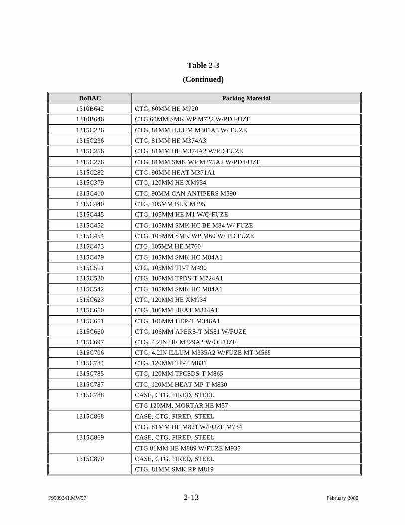
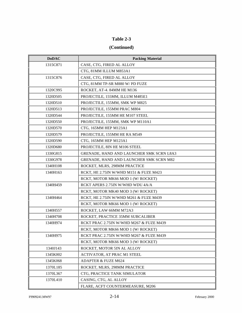
2-3 Residues Fired Downrange ............................................................................................ 2-11
2-4 Residues Eliminated by Process Knowledge ................................................................. 2-16
2-5 Residues (by Waste Stream) Requiring Sampling......................................................... 2-18
2-6 Method to Achieve Characterization Requirements ...................................................... 2-23
3-1 General Sampling and Analysis Requirements for Each Waste Stream.......................... 3-1
3-2 Sample Containers and Minimum Sample Amounts..................................................... 3-18
3-3 Acceptance Criteria........................................................................................................ 3-21
3-4 Holding Times for Chemical Analyses on Solid Samples............................................. 3-23
4-1 Summary of Sampling and Analysis................................................................................ 4-2
4-2 Comparison of Ammunition Size Designations .............................................................. 4-4
4-3 Primer Mix for 12 Gauge Shotgun Cartridges................................................................. 4-6
4-4 Propellant Mixes for 12 Gauge Shotgun Cartridges ........................................................ 4-7
4-5 12 Gauge Shotgun Cartridge Cases ................................................................................. 4-7
4-6 Primer Mix for 5.56mm Cartridges ................................................................................. 4-9
4-7 Propellant Mixes for 5.56mm Cartridges....................................................................... 4-10
4-8 5.56mm Cartridge Cases................................................................................................ 4-11
4-9 Primer Mix for .22 Caliber Cartridges........................................................................... 4-12
4-10 Propellant Mix for .22 Caliber Cartridges ..................................................................... 4-13
4-11 .22 Caliber Cartridge Cases ........................................................................................... 4-13
4-12 Primer Mix for .30 Caliber Cartridges........................................................................... 4-15
4-13 Propellant Mixes for .30 Caliber Cartridges .................................................................. 4-16
4-14 .30 Caliber Cartridge Cases ........................................................................................... 4-17
4-15 Primer Mix for 9mm Cartridges .................................................................................... 4-19
4-16 Propellant Mix for 9mm Cartridges............................................................................... 4-19
4-17 9mm Cartridge Cases..................................................................................................... 4-20
4-18 Primer Mix for .45 Caliber Cartridge ............................................................................ 4-22
F9909241.MW97 xii February 2000
LIST OF TABLES (Continued)
Page
4-19 Propellant Mix for .45 Caliber Cartridge ....................................................................... 4-22
4-20 .45 Caliber Cartridge Case............................................................................................. 4-23
4-21 Primer Mixes for 7.62mm Cartridges ............................................................................ 4-25
4-22 Propellant Mixes for 7.62mm Cartridges ...................................................................... 4-25
4-23 7.62mm Cartridge Cases................................................................................................ 4-26
4-24 Primer Mix for .50 Caliber Cartridges........................................................................... 4-29
4-25 Propellant Mixes for .50 Caliber Cartridges .................................................................. 4-29
4-26 .50 Caliber Cartridge Cases ........................................................................................... 4-31
4-27 Primer Mixes for 40mm Cartridges ............................................................................... 4-33
4-28 Group 9 Propellant Mixes.............................................................................................. 4-33
4-29 40mm Cartridge Cases................................................................................................... 4-34
4-30 First Fire, Ignition, Delay, and Primer Mixes for the M201A1 Grenade Fuze.............. 4-37
4-31 Grenade Fuze (M201A1)............................................................................................... 4-37
4-32 First Fire, Ignition, Delay, and Primer Mixes for M227 Grenade Fuze ........................ 4-39
4-33 Grenade Fuze (M227) .................................................................................................... 4-39
4-34 Filler and Solder Composition of AN-M8 Smoke Grenades......................................... 4-41
4-35 Smoke Grenade (AN-M8 HC) Cases............................................................................. 4-42
4-36 Filler and Solder Composition for M48 Red Smoke Grenades ..................................... 4-43
4-37 Smoke Grenade (M48 Red) Case................................................................................... 4-44
4-38 Filler and Solder Composition for M18 Red Smoke Grenades ..................................... 4-46
4-39 Smoke Grenade (M18 Red) Case................................................................................... 4-46
4-40 Primer Mix Composition for 14.5mm Training Cartridges ........................................... 4-48
4-41 Propellant Mix Composition for 14.5mm Training Cartridges ..................................... 4-48
4-42 14.5mm Training Cartridge Cases ................................................................................. 4-49
4-43 Primer Mix Composition for 25mm Cartridges............................................................. 4-51
4-44 Flash Tube Composition for 25mm Cartridges ............................................................. 4-51
4-45 Propellant Mix Compositions for 25mm Cartridges...................................................... 4-52
4-46 25mm Cartridge Cases................................................................................................... 4-52
F9909241.MW97 xiii February 2000
LIST OF TABLES (Continued)
Page
4-47 Primer Mix Composition for 30mm Cartridge .............................................................. 4-54
4-48 Flash Tube Composition for 30mm Cartridges ............................................................. 4-55
4-49 Propellant Mix Composition for 30mm Cartridges ....................................................... 4-55
4-50 30mm Cartridge Cases................................................................................................... 4-56
4-51 75 to 165mm Cartridge Cases........................................................................................ 4-58
4-52 Filler and Solder Composition for M18 Green Smoke Grenade ................................... 4-61
4-53 M18 Green Smoke Grenade........................................................................................... 4-61
4-54 Filler and Solder Composition for M18 Yellow Smoke Grenade ................................. 4-63
4-55 M18 Yellow Smoke Grenade......................................................................................... 4-63
4-56 Primer Mix Composition for M82 Percussion Primer Cartridge ................................... 4-65
4-57 Propellant Mix Composition for M82 Percussion Primer Cartridge ............................. 4-66
4-58 M82 Percussion Primer Cartridge Case......................................................................... 4-66
4-59 Primer Mix Composition for M60 Firing Device .......................................................... 4-68
4-60 M60 Firing Device......................................................................................................... 4-69
4-61 Ignition and Main Charge Composition for M6 Electric Blasting Cap......................... 4-70
4-62 M6 Electric Blasting Cap............................................................................................... 4-71
4-63 Main Charge Composition for M7 Nonelectric Blasting Cap ....................................... 4-73
4-64 M7 Nonelectric Blasting Cap......................................................................................... 4-73
4-65 Primer Mix Composition for M5 Firing Device ............................................................ 4-75
4-66 M5 Firing Device........................................................................................................... 4-75
4-67 Riot Control Hand Grenade CS M7A3.......................................................................... 4-77
4-68 Smoke Mix Compositions for ABC-M5 HC Smoke Pot............................................... 4-79
4-69 ABC-M5 HC Smoke Pot ............................................................................................... 4-79
4-70 Primer Mix Composition for TH3 AN-M14 Incendiary Hand Grenade ....................... 4-81
4-71 TH3 AN-M14 Incendiary Hand Grenade ...................................................................... 4-81
4-72 M18 Violet Smoke Hand Grenade................................................................................. 4-83
4-73 Energetic Composition for Floating Smoke Pot Type HC M4A2................................. 4-85
4-74 Floating Smoke Pot Type HC M4A2............................................................................. 4-85
F9909241.MW97 xiv February 2000
LIST OF TABLES (Continued)
Page
4-75 Primer Mix Composition for Nonelectric Blasting Cap M11........................................ 4-87
4-76 M11 Nonelectric Blasting Cap....................................................................................... 4-88
4-77 Primer Mix Composition for Nonelectric Blasting Cap M12 and M13 ........................ 4-90
4-78 Nonelectric Blasting Cap M12/M13.............................................................................. 4-90
4-79 Primer Mix Composition for Nonelectric Blasting Cap M14........................................ 4-92
4-80 Nonelectric Blasting Cap M14....................................................................................... 4-93
4-81 Primer Mix Composition for Nonelectric Blasting Cap M15........................................ 4-94
4-82 Nonelectric Blasting Cap M15....................................................................................... 4-95
4-83 Primer Mix Composition for Personal Distress Flare Kit.............................................. 4-96
4-84 Personal Distress Flare Kit............................................................................................. 4-97
4-85 White Smoke Mix Composition for 155mm Smoke Canister, MC M1........................ 4-98
4-86 155mm Smoke Canister, HC M1................................................................................... 4-98
4-87 Primer Mix for 10 Gauge Shotgun Cartridges............................................................. 4-100
4-88 10 Gauge Shotgun Cartridge Cases ............................................................................. 4-101
4-89 Primer Mix Composition for M81 Firing Device ........................................................ 4-103
4-90 M81 Firing Device....................................................................................................... 4-103
4-91 Primer Mix Composition for 20mm Cartridges........................................................... 4-105
4-92 Propellant Mix Compositions for 20mm Cartridges.................................................... 4-105
4-93 20mm Cartridge Cases................................................................................................. 4-106
4-94 Primer Mix Composition for 25.4mm Cartridge ......................................................... 4-108
4-95 25.4mm Cartridge Case................................................................................................ 4-108
F9909241.MW97 xv February 2000
ACRONYMS
AEC U.S. Army Environmental Center
ASP Ammunition Supply Point
BMP Best Management Practice
CERCLA Comprehensive Environmental Response, Compensation, and Liability Act
CFR Code of Federal Regulations
COC Chain-of-Custody
DNT Dinitrotoluene
DoD U.S. Department of Defense
DoDAC DoD Ammunition Code
DoDIC DoD Item Code
DQO Data Quality Objective
DRMO Defense Reutilization and Marketing Office
EPA U.S. Environmental Protection Agency
FORSCOM Forces Command
HC Hexachloroethane
HE High Explosive
HQDA Headquarters U.S. Department of Army
HWM Hazardous Waste Management
LDR Land Disposal Restriction
MDL Method Detection Limit
MIDAS Munitions Items Disposition Action System
MRIC Munitions Rule Implementation Council
PARCC Precision, Accuracy, Representativeness, Completeness, and Comparability
PCB Polychlorinated Biphenyl
PEP Propellants, Explosives, and Pyrotechnics
PETN Pentaerythritol Tetranitrate
ppm parts per million
QA Quality Assurance
F9909241.MW97 xvi February 2000
ACRONYMS (Continued)
QC Quality Control
Radian Radian International
RCRA Resource Conservation and Recovery Act
RPD Relative Percent Difference
SOP Standard Operating Procedure
SVOC Semivolatile Organic Compound
TCLP Toxicity Characteristic Leaching Procedure
TRADOC Training and Doctrine Command
UHC Underlying Hazardous Constituent
VOC Volatile Organic Compound
F9909241.MW97 xvii February 2000
EXECUTIVE SUMMARY
The Headquarters U.S. Department of Army (HQDA) is working to promote a
consistent approach to the management of range residues being removed from its training ranges.
In support of HQDA, the U.S. Army Environmental Center has taken steps toward meeting this
objective. This report provides a strategy for characterizing range scrap, particularly firing point
scrap, items based on the regulatory framework and the inventory of firing point range scrap
identified in an earlier phase of this project and presented in the Range Scrap (Firing Point)
Study Data Review and Inventory Report, June 1999. “Firing point” range scrap as referred to in
this report includes items that, under typical circumstances, are generated and removed from the
firing point/line, as well as items that are routinely returned to Army installation ammunition
supply points, recycle yards, Defense Reutilization and Marketing Office scrap yards, and range
clearance scrap yards.
Accomplishment of the HQDA objective will require additional actions, including
the development of item-specific waste profiles and best management practices (BMPs) for the
inventory.
The range scrap inventory and regulatory framework provide a basis for a
systematic approach to the development of item-specific profiles. The profiles will be created
using existing information and, if necessary, through laboratory analysis as prescribed in this
report. BMPs for the scrap inventory (firing point) will be developed in accordance with item
profiles and in consideration of other regulatory requirements and scrap metal industry standards.
Completion of this study will assist generators of range scrap to manage those
items in a consistent manner and in accordance with applicable regulatory requirements.

This page intentionally left blank.
F9909241.MW97 1-1 February 2000
1.0 INTRODUCTION
The U.S. Army Environmental Center (AEC) has initiated an inventory and
characterization of solid waste on ranges. This strategy report addresses the characterization
requirements for the inventory of firing point range scrap identified in Phase I of this project,
Range Scrap (Firing Point) Study Data Review and Inventory Report, June 1999.
1.1 Background
During the development of the Munitions Rule Implementation Plan, the
Munitions Rule Implementation Council (MRIC) recognized the emerging issues regarding the
requirements for management of recyclable range scrap metal to comply with the Military
Munitions Rule and existing Resource Conservation and Recovery Act (RCRA) requirements. In
March 1998, MRIC requested the U.S. Department of Defense (DoD) Hazardous Waste
Management (HWM) Subcommittee to determine whether DoD should undertake a waste
characterization (hazardous or nonhazardous) of recyclable residue resulting from range
operations. The DoD HWM Subcommittee assigned a working group to review the RCRA issues
and to determine the requirements for a waste determination of recyclable range scrap metal.
The DoD HWM Subcommittee initially determined that DoD can either (1) take
advantage of a RCRA exclusion for “excluded scrap metal” (in those few states that have
adopted this provision) from the definition of a regulatory “solid waste” or (2) use process
knowledge to declare scrap metal resulting from range operations as hazardous waste and take
advantage of the exemption for “scrap metal” from the bulk of RCRA Subtitle C requirements.
However, other related issues were raised that are not directly addressed by this approach, such
as:
Ø Does the RCRA exclusion for “excluded scrap metal” and/or the exemptionfor “scrap metal” apply to residual constituents (e.g., explosive residue) thatmay be present on the scrap metal?
F9909241.MW97 1-2 February 2000
Ø By assuming all range scrap metal is hazardous, these items are potentiallysubject to overly strict regulatory RCRA interpretations by states and U.S.Environmental Protection Agency (EPA) regional offices.
Ø Are additional management procedures needed to ensure that these items willmeet the definition of “excluded scrap metal” and “scrap metal”?
Ø Are additional management procedures needed to prevent release ofhazardous constituents, which may be present on the scrap metal items, and tominimize concerns?
While DoD may take advantage of the exclusion for “excluded scrap metal” and
the exemption for “scrap metal,” the DoD HWM Subcommittee concluded that characterization
and a regulatory framework are needed to:
Ø Address the unique characteristics of specific items (no “one size fits all”),
Ø Provide a consistent management approach for each item, and
Ø Provide the best benefit relative to regulatory position for addressingconcerns.
In addition to compiling data to characterize those items that require a hazardous
waste determination, sampling and analysis of range residues would:
Ø Support DoD decision-making on appropriate management practices;
Ø Avoid subjecting items to overly strict regulatory interpretations;
Ø Identify underlying hazardous constituents (UHCs);
Ø Minimize on-site RCRA corrective action liability associated withmismanaged items;
Ø Minimize long-term Comprehensive Environmental Response, Compensation,and Liability Act (CERCLA) liability;
Ø Provide assurance to downstream processors; and
Ø Provide a source of data for range evaluation and potential remedial actions.
To address the issues discussed above, AEC is conducting the Range Scrap Study
to develop the regulatory framework for management of range residues, to compile data to
F9909241.MW97 1-3 February 2000
characterize those items that require a waste characterization, and to recommend best
management practices (BMPs) for managing these items in accordance with RCRA.
1.2 Project Requirements
The purpose of this project is to assist Headquarters U.S. Department of Army
(HQDA) and AEC with identification and characterization of solid waste and range residue
(range scrap) generated by military personnel from the intended use (firing and training) of
munitions and other training propellants, explosives, and pyrotechnics (PEP) items at training
ranges. The primary objective of this project is to perform a comprehensive inventory of the
items utilized in support of Army training and mission activities on ranges at the firing point,
characterize these items in accordance with RCRA, and develop environmental BMPs for these
items, including all aspects from handling to final disposition.
This project is being executed in a phased approach to provide AEC/HQDA with:
Phase I
Ø Development of a regulatory framework for managing range scrap;
Ø An inventory of solid waste and residual material generated during trainingexercises;
Phase II
Ø Development of a characterization scheme for residual material, includinganalytical recommendations;
Ø Development of characterization and characterization profiles for theinventory; and
Phase III
Ø Development of BMPs for the inventory, consistent with profiles developed inthe characterization phase.
F9909241.MW97 1-4 February 2000
This report presents the scheme for characterizing range scrap as required in
Phase II. The regulatory framework and inventory developed in Phase I are utilized in this
strategy report to identify the data needed to meet the objectives of this study.
1.3 Organization of Report
This strategy report includes the following sections:
Ø Section 1 provides and introduction and description of the project.
Ø Section 2 presents the data quality objectives (DQOs) developed forcharacterizing range scrap.
Ø Section 3 discusses the general sampling and analytical methods to beperformed.
Ø Section 4 provides the characterization rationale for each waste stream andthe specific sampling and analysis requirements for each scrap item.
Ø Section 5 provides the data reduction, validation, and reporting requirements,as well as the approach for interpreting the results to satisfy the project DQOs.
F9909241.MW97 2-1 February 2000
2.0 PROJECT DQOs
The purpose of this project is to assist HQDA and AEC with the identification and
characterization of solid waste and range residue (range scrap) generated by military personnel
from the intended use (firing and training) of munitions and other training PEP items at
training/testing ranges. The primary objective of this project is to perform a comprehensive
inventory of the items used in support of Army training and range activities, characterize these
items in accordance with the regulatory framework developed for the project, and develop
environmental BMPs for these items, including all aspects from handling to final disposition.
The DQO process summarized in EPA QA/G-4, Guidance Planning for Data
Collection in Support of Environmental Decision Making Using the Data Quality Objective
Process, was used to develop a logical and formal approach to characterization and development
of BMPs and is presented in this strategy report. The DQO approach is a process for making
decisions in an uncertain environment. It is a predicted iterative process that drives the collection
of data for the purpose of characterization, technical evaluation, and election and implementation
of BMPs.
The DQO process is listed below and described in the following sections.
1. State the problem,
2. Identify the decision,
3. Identify inputs to the decision,
4. Define study boundaries,
5. Develop a decision rule,
6. Specify limits on decision errors, and
7. Optimize the design for obtaining data.
F9909241.MW97 2-2 February 2000
2.1 Problem Statement
In response to many new challenges rising from an interest in safety and
environmental issues associated with the disposition of residue from ranges, AEC is conducting
an inventory and characterization of solid waste generated from the use of munitions on Army
troop training ranges. The overall goal is to promote a consistent approach to the management of
these residue items and do so in accordance with environmental requirements. Waste
characterization must:
Ø Address the unique characteristics of specific items (no “one size fits all”),
Ø Provide a consistent management approach for each item, and
Ø Provide the best benefit relative to a regulatory position for addressingconcerns.
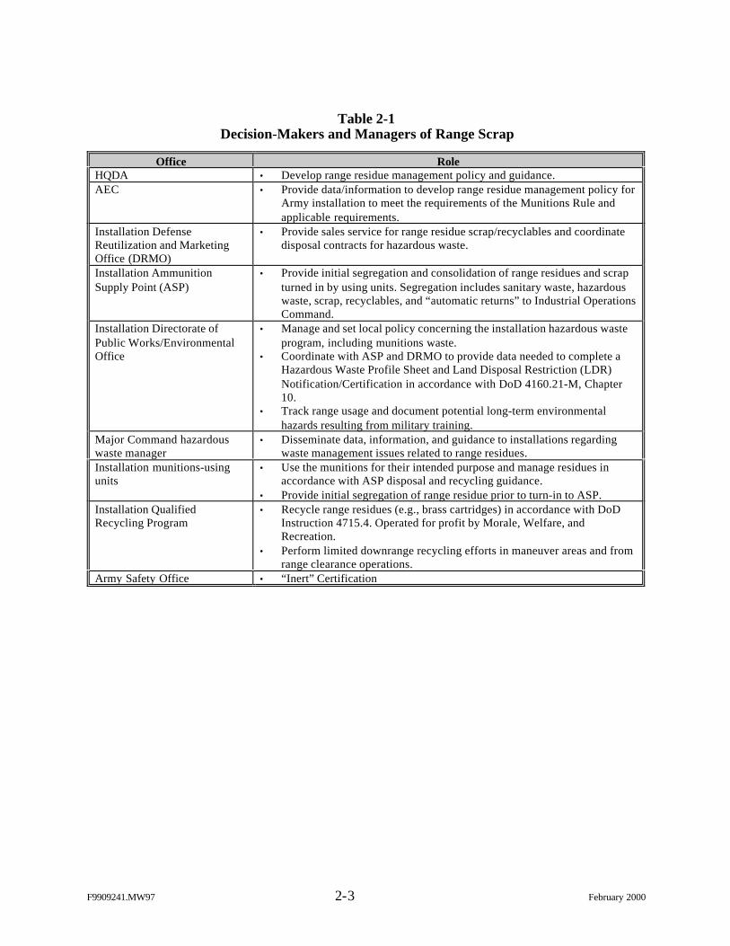
To achieve this goal, each organization that has responsibilities for management
of range residues was identified. These decision-makers and users are presented in Table 2-1,
along with a summary of their impact within the decision-making process.
Site visits were conducted at the responsible organizations (Table 2-1) of three
Army installations to aid in defining waste management activities/responsibilities and developing
the inventory for this project. This element was crucial in identifying inputs to the decision,
study boundaries, and decision rules for the project DQOs.
2.2 Identify the Decision
Decision Statement: Which range residues require characterization sampling to
make a hazardous waste determination and validate long-term development of BMPs for
effective range residue management?
Figure 2-1 provides the federal regulatory framework that drives overall range
residue management. Using this flowchart, the project team analyzes each range residue
F9909241.MW97 2-3 February 2000
Table 2-1Decision-Makers and Managers of Range Scrap
Office RoleHQDA • Develop range residue management policy and guidance.AEC • Provide data/information to develop range residue management policy for
Army installation to meet the requirements of the Munitions Rule andapplicable requirements.
Installation DefenseReutilization and MarketingOffice (DRMO)
• Provide sales service for range residue scrap/recyclables and coordinatedisposal contracts for hazardous waste.
Installation AmmunitionSupply Point (ASP)
• Provide initial segregation and consolidation of range residues and scrapturned in by using units. Segregation includes sanitary waste, hazardouswaste, scrap, recyclables, and “automatic returns” to Industrial OperationsCommand.
Installation Directorate ofPublic Works/EnvironmentalOffice
• Manage and set local policy concerning the installation hazardous wasteprogram, including munitions waste.
• Coordinate with ASP and DRMO to provide data needed to complete aHazardous Waste Profile Sheet and Land Disposal Restriction (LDR)Notification/Certification in accordance with DoD 4160.21-M, Chapter10.
• Track range usage and document potential long-term environmentalhazards resulting from military training.
Major Command hazardouswaste manager
• Disseminate data, information, and guidance to installations regardingwaste management issues related to range residues.
Installation munitions-usingunits
• Use the munitions for their intended purpose and manage residues inaccordance with ASP disposal and recycling guidance.
• Provide initial segregation of range residue prior to turn-in to ASP.Installation QualifiedRecycling Program
• Recycle range residues (e.g., brass cartridges) in accordance with DoDInstruction 4715.4. Operated for profit by Morale, Welfare, andRecreation.
• Perform limited downrange recycling efforts in maneuver areas and fromrange clearance operations.
Army Safety Office • “Inert” Certification
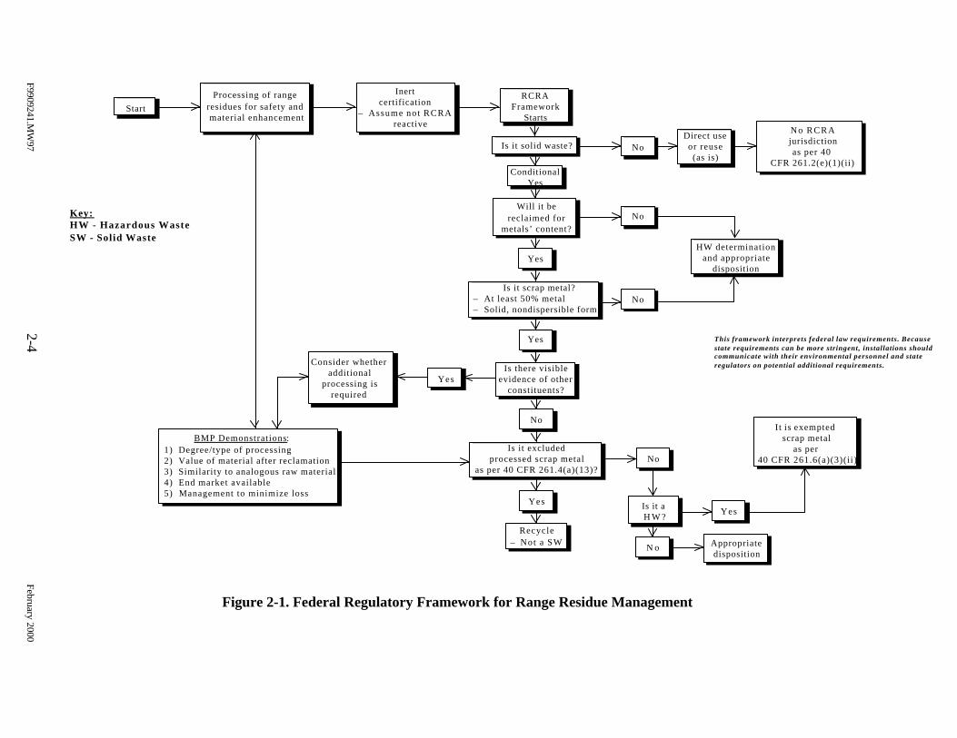
Figure 2-1. Federal Regulatory Framework for Range Residue Management
Is it solid waste?
ConditionalYes
Is it scrap metal?– At least 50% metal– Solid, nondispersible form
Is there visibleevidence of other
constituents?
Yes
Yes
RCRAFramework
Starts
Will it bereclaimed for
metals’ content?
Yes
Is it excludedprocessed scrap metal
as per 40 CFR 261.4(a)(13)?
Recycle– Not a SW
No
BMP Demonstrations:1) Degree/type of processing2) Value of material after reclamation3) Similarity to analogous raw material4) End market available5) Management to minimize loss
Key:HW - Hazardous WasteSW - Solid Waste
This framework interprets federal law requirements. Becausestate requirements can be more stringent, installations shouldcommunicate with their environmental personnel and stateregulators on potential additional requirements.
Yes
Consider whetheradditional
processing isrequired
No
No
No
Direct useor reuse(as is)
No RCRAjurisdictionas per 40
CFR 261.2(e)(1)(ii)
HW determinationand appropriate
disposition
No
Is it a H W ?
It is exempted scrap metal
as per 40 CFR 261.6(a)(3)(ii)
Yes
N o Appropriatedisposition
StartProcessing of range
residues for safety and material enhancement
Inertcertification
– Assume not RCRA reactive
F9909241.MW
972-4
February 2000
F9909241.MW97 2-5 February 2000
waste stream (e.g., small arms ammunition) and recommends specific residues requiring
characterization before management and final disposition requirements are defined.
The end result of this determination is a sampling priority list and protocol for
characterization. Based on the regulatory framework presented in Figure 2-1, each residue or
residue grouping will be classified into one of these potential outcomes:
Ø Nonhazardous solid waste subject to Subtitle D standards,
Ø Hazardous solid waste subject to RCRA regulation,
Ø Directly used/reused item excluded from the definition of RCRA solid waste,
Ø Processed scrap metal excluded from the definition of RCRA solid waste, and
Ø Scrap metal exempted from the bulk of RCRA requirements.
This study is designed to acquire information to support DoD decision-making on
appropriate management practices mentioned earlier, particularly to support the position that
metallic range residues are excluded “processed scrap metal.” In addition to performing the
hazardous waste determination, other data/analysis are required to address issues related to
“other constituents” associated with scrap metal items and to address the five evaluation factors
cited by EPA (Figure 2-1), as well as address standards set by the scrap metal recycling industry.
These data requirements will provide:
Ø Identification of UHCs. For those range residues that are hazardous wastesthat cannot be recycled (such as some smoke pots) and that, therefore, aresubject to the RCRA land disposal restrictions (LDRs). As a generator, DoDmust identify UHCs to the treatment or disposal facility to ensure propertreatment before land disposal.
Ø Minimization of long-term CERCLA liability. To the extent that scrapitems have been adequately characterized and subject to appropriatemanagement controls (at the front end), this risk may be minimized.
Ø Assurance to downstream processors . Currently, secondary smelting orfurnace operations that input scrap metal are not subject to RCRA regulationbecause the scrap metal itself is not a “hazardous waste.”1 One of their biggest
1Smelters and furnaces that process hazardous waste (vs. excluded/exempt scrap metal) for metal recovery may beexempt from RCRA pursuant to 40 CFR 266.100(c) as long as certain demonstrations are made.
F9909241.MW97 2-6 February 2000
regulatory risks is that “suspect” scrap metal input could mean that EPA willapply the RCRA permitting and technical standards at 40 Code of FederalRegulations (CFR) 266 (industrial furnaces that process hazardous waste).Again, having a controlled and thorough characterization scheme at thegenerator end should minimize these concerns, both to industry as well as toEPA.
Characterization requirements must address these additional data needs for range
scrap.
2.3 Identify Inputs to the Decision
A variety of sources are used to prioritize the characterization. The two primary
sources of data are the inventory report generated during Phase I of the project and the technical
expertise of the project staff members in the areas of munitions, environmental sampling, and
regulatory analysis. Additional sources of information include the items listed below. As the
project progresses, additional inputs may be identified and added to the source list.
Ø Previous sampling efforts conducted by the military (e.g., U.S. Army Centerfor Health Promotion and Preventive Medicine, Dugway Proving Ground) andcivilian contractors (e.g., the Subpart X permit application prepared forMarine Corps Air Station Beaufort);
Ø U.S. military databases, such as Munitions Items Disposition Action System(MIDAS) and the Ammunition Book Complete;
Ø Ammunition Instruction Notices for disposition and management ofmunitions; and
Ø Guidance documents on environmental sampling techniques and statisticalmodeling.
2.3.1 Initial Screening
To initially screen the range scrap inventory presented in the Range Scrap (Firing
Point) Study Data Review and Inventory Report, June 1999, the project team has used the input
sources to consolidate and limit the residues, filtering out those items already having enough data
to make a decision on disposition. Appendix A provides an updated version of the range scrap
F9909241.MW97 2-7 February 2000
inventory. Some of the basic information that was used to screen the inventory includes
constituent and materials listing, current disposition procedures, points of generation, and
process knowledge.
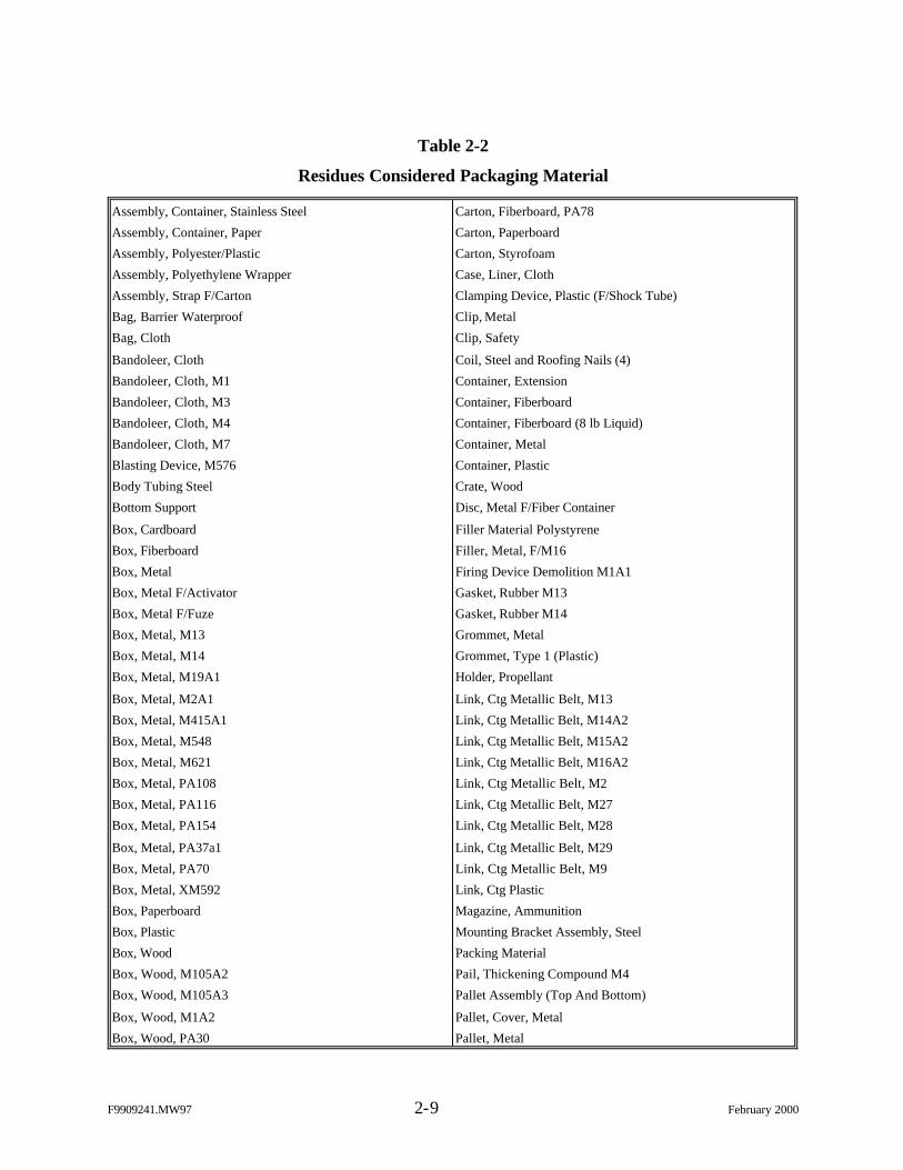
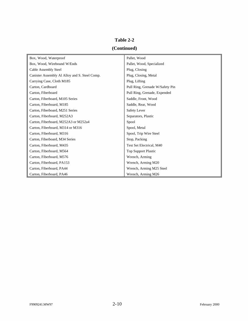
The first step of the screening process was removal of residues classified as
packaging materials and that are inert. Table 2-2 contains a listing of packing materials that were
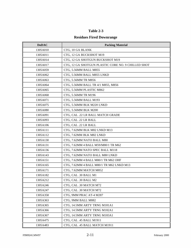
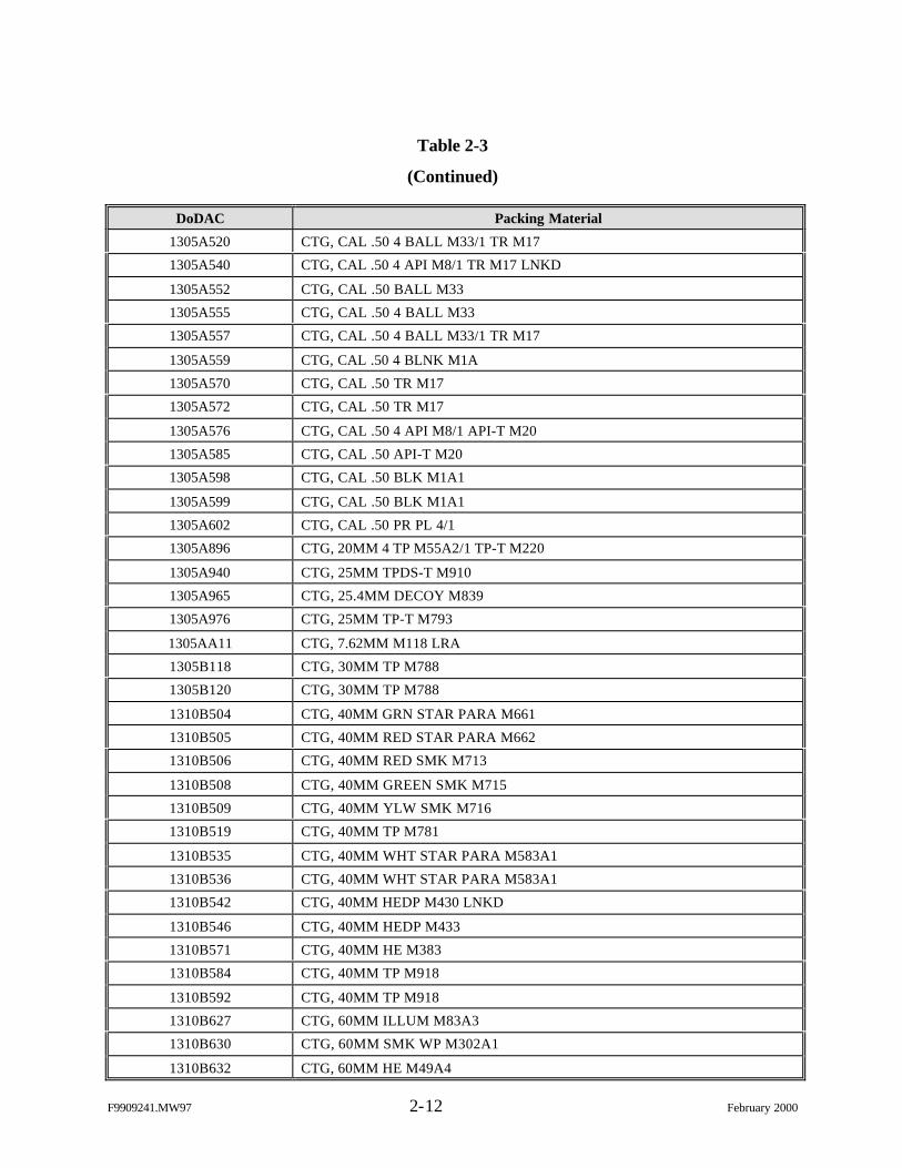
eliminated from sampling and analysis due to process knowledge. Second, after removal of the
packaging items, items that were fired or used downrange (i.e., bullet slugs and rockets) were
eliminated. These items are listed in Table 2-3. Finally, items used at the firing point or within
the training maneuver area were removed if, due to process knowledge information (constituent
makeup, MIDAS data, etc.), they contain no RCRA hazardous constituents or do not produce a
firing point scrap item and do not require sampling and analysis. Table 2-4 lists those items
removed by process knowledge of the residue.
2.3.2 Identifying Waste Streams for Characterization
After screening the inventory as discussed in Section 2.3.1, several munitions
items [DoD Ammunition Codes (DoDACs)] remain that produce range scrap (firing point),
which require characterization. Review of the remaining munitions items (DoDACs) in the
inventory indicates that many items produce the same type of range scrap. For example,
DoDACs 1305A059, 1305A062, 1305A063, 1305A064, 1305A065, 1305A068, 1305A071,
1305A075, and 1305A080 (various types of 5.56mm cartridges) all produce a 5.56mm cartridge
case as a firing point range scrap item. The range scrap item (5.56mm cartridge case) is
considered one waste stream with the associated DoDACs in the inventory as listed above. Table
2-5 provides the reduced/filtered inventory of range residue (firing point and training maneuver
area) waste streams that require sampling due to suspected contaminants and/or lack of process
knowledge information.
Since the various munitions items associated with a waste stream or scrap item
may contain slightly different constituents/materials or constituents/materials in different
amounts, this information was reviewed for all DoDACs within a waste stream to ensure there
F9909241.MW97 2-8 February 2000
are no significant variations. This information may also be used to determine which munitions
item (DoDAC) within the waste stream represents the most conservative choice for
characterization. The characterization for this waste stream may then be focused on one DoDAC
within the waste stream instead of designing a sampling program to account for all potential
variations. Optimizing the characterization scheme in this way is discussed further is
Section 2.7.2. This approach is also crucial in conserving limited project resources given the
quantity of munitions items associated with the scrap items requiring characterization.
2.4 Define Study Boundaries
The overall study boundaries are training munitions used on U.S. Army Forces
Command (FORSCOM) and U.S. Army Training and Doctrine Command (TRADOC) ranges
and their residues that are generated either at the Ammunition Supply Point (ASP), the firing
point, or within the training/maneuver area. It does not include items that are downrange or
consumed completely in process. The inventory of range scrap collected from downrange is
preliminary and will be addressed at a later date to supplement this effort. However, the
regulatory framework (Figure 2-1) and the DQOs presented in this effort are applicable to all
range residues.
2.5 Develop Decision Rules
The regulatory framework presented in Figure 2-1 provides the key decision
points for this study, which infer the following “if/then” decision rules:
Ø If an item is determined not to be RCRA hazardous, then the item may besubject only to Subtitle D standards.
Ø If a nonrecyclable item is determined to be RCRA hazardous, then the itemmust be managed as RCRA hazardous waste.
Ø If a scrap metal item is determined to be RCRA hazardous, thenmanagement/processing (Figure 2-1 BMP demonstrations/five EPAevaluation factors) will be considered to take advantage of the RCRAexclusion and exemption.
F9909241.MW97 2-9 February 2000
Table 2-2
Residues Considered Packaging Material
Assembly, Container, Stainless Steel
Assembly, Container, Paper
Assembly, Polyester/Plastic
Assembly, Polyethylene Wrapper
Assembly, Strap F/Carton
Bag, Barrier Waterproof
Bag, Cloth
Bandoleer, Cloth
Bandoleer, Cloth, M1
Bandoleer, Cloth, M3
Bandoleer, Cloth, M4
Bandoleer, Cloth, M7
Blasting Device, M576
Body Tubing Steel
Bottom Support
Box, Cardboard
Box, Fiberboard
Box, Metal
Box, Metal F/Activator
Box, Metal F/Fuze
Box, Metal, M13
Box, Metal, M14
Box, Metal, M19A1
Box, Metal, M2A1
Box, Metal, M415A1
Box, Metal, M548
Box, Metal, M621
Box, Metal, PA108
Box, Metal, PA116
Box, Metal, PA154
Box, Metal, PA37a1
Box, Metal, PA70
Box, Metal, XM592
Box, Paperboard
Box, Plastic
Box, Wood
Box, Wood, M105A2
Box, Wood, M105A3
Box, Wood, M1A2
Box, Wood, PA30
Carton, Fiberboard, PA78
Carton, Paperboard
Carton, Styrofoam
Case, Liner, Cloth
Clamping Device, Plastic (F/Shock Tube)
Clip, Metal
Clip, Safety
Coil, Steel and Roofing Nails (4)
Container, Extension
Container, Fiberboard
Container, Fiberboard (8 lb Liquid)
Container, Metal
Container, Plastic
Crate, Wood
Disc, Metal F/Fiber Container
Filler Material Polystyrene
Filler, Metal, F/M16
Firing Device Demolition M1A1
Gasket, Rubber M13
Gasket, Rubber M14
Grommet, Metal
Grommet, Type 1 (Plastic)
Holder, Propellant
Link, Ctg Metallic Belt, M13
Link, Ctg Metallic Belt, M14A2
Link, Ctg Metallic Belt, M15A2
Link, Ctg Metallic Belt, M16A2
Link, Ctg Metallic Belt, M2
Link, Ctg Metallic Belt, M27
Link, Ctg Metallic Belt, M28
Link, Ctg Metallic Belt, M29
Link, Ctg Metallic Belt, M9
Link, Ctg Plastic
Magazine, Ammunition
Mounting Bracket Assembly, Steel
Packing Material
Pail, Thickening Compound M4
Pallet Assembly (Top And Bottom)
Pallet, Cover, Metal
Pallet, Metal
F9909241.MW97 2-10 February 2000
Table 2-2
(Continued)
Box, Wood, Waterproof
Box, Wood, Wirebound W/Ends
Cable Assembly Steel
Canister Assembly Al Alloy and S. Steel Comp.
Carrying Case, Cloth M185
Carton, Cardboard
Carton, Fiberboard
Carton, Fiberboard, M105 Series
Carton, Fiberboard, M185
Carton, Fiberboard, M251 Series
Carton, Fiberboard, M252A3
Carton, Fiberboard, M252A3 or M252a4
Carton, Fiberboard, M314 or M316
Carton, Fiberboard, M316
Carton, Fiberboard, M34 Series
Carton, Fiberboard, M435
Carton, Fiberboard, M564
Carton, Fiberboard, M576
Carton, Fiberboard, PA153
Carton, Fiberboard, PA44
Carton, Fiberboard, PA46
Pallet, Wood
Pallet, Wood, Specialized
Plug, Closing
Plug, Closing, Metal
Plug, Lifting
Pull Ring, Grenade W/Safety Pin
Pull Ring, Grenade, Expended
Saddle, Front, Wood
Saddle, Rear, Wood
Safety Lever
Separators, Plastic
Spool
Spool, Metal
Spool, Trip Wire Steel
Stop, Packing
Test Set Electrical, M40
Top Support Plastic
Wrench, Arming
Wrench, Arming M20
Wrench, Arming M25 Steel
Wrench, Arming M26
F9909241.MW97 2-11 February 2000
Table 2-3
Residues Fired Downrange
DoDAC Packing Material
1305A010 CTG, 10 GA BLANK
1305A011 CTG, 12 GA BUCKSHOT M19
1305A014 CTG, 12 GA SHOTGUN BUCKSHOT M19
1305A017 CTG, 12 GA SHOTGUN PLASTIC CORE NO. 9 CHILLED SHOT
1305A059 CTG, 5.56MM BALL M855
1305A062 CTG, 5.56MM BALL M855 LNKD
1305A063 CTG, 5.56MM TR M856
1305A064 CTG, 5.56MM BALL TR 4/1 M855, M856
1305A065 CTG, 5.56MM PLASTIC M862
1305A068 CTG, 5.56MM TR M196
1305A071 CTG, 5.56MM BALL M193
1305A075 CTG, 5.56MM BLK M220 LNKD
1305A080 CTG, 5.56MM BLK M200
1305A091 CTG, CAL .22 LR BALL MATCH GRADE
1305A093 CTG, CAL .22 LR BALL
1305A106 CTG, CAL .22 LR BALL
1305A111 CTG, 7.62MM BLK M82 LNKD M13
1305A112 CTG, 7.62MM BLK M82 LNKD
1305A130 CTG, 7.62MM NATO BALL M80
1305A131 CTG, 7.62MM 4 BALL M59/M80/1 TR M62
1305A136 CTG, 7.62MM NATO SPEC BALL M118
1305A143 CTG, 7.62MM NATO BALL M80 LNKD
1305A151 CTG, 7.62MM 4 BALL M80/1 TR M62 OHF
1305A165 CTG, 7.62MM 4 BALL M80/1 TR M62 LNKD M13
1305A171 CTG, 7.62MM MATCH M852
1305A182 CTG, CAL .30 BALL M1
1305A212 CTG, CAL .30 BALL M2
1305A246 CTG, CAL .30 MATCH M72
1305A247 CTG, CAL .30 MATCH M72
1305A358 CTG, 9MM PRAC AT-4 M287
1305A363 CTG, 9MM BALL M882
1305A365 CTG, 14.5MM ARTY TRNG M181A1
1305A366 CTG, 14.5MM ARTY TRNG M182A1
1305A367 CTG, 14.5MM ARTY TRNG M183A1
1305A475 CTG, CAL .45 BALL M1911
1305A483 CTG, CAL .45 BALL MATCH M1911
F9909241.MW97 2-12 February 2000
Table 2-3
(Continued)
DoDAC Packing Material
1305A520 CTG, CAL .50 4 BALL M33/1 TR M17
1305A540 CTG, CAL .50 4 API M8/1 TR M17 LNKD
1305A552 CTG, CAL .50 BALL M33
1305A555 CTG, CAL .50 4 BALL M33
1305A557 CTG, CAL .50 4 BALL M33/1 TR M17
1305A559 CTG, CAL .50 4 BLNK M1A
1305A570 CTG, CAL .50 TR M17
1305A572 CTG, CAL .50 TR M17
1305A576 CTG, CAL .50 4 API M8/1 API-T M20
1305A585 CTG, CAL .50 API-T M20
1305A598 CTG, CAL .50 BLK M1A1
1305A599 CTG, CAL .50 BLK M1A1
1305A602 CTG, CAL .50 PR PL 4/1
1305A896 CTG, 20MM 4 TP M55A2/1 TP-T M220
1305A940 CTG, 25MM TPDS-T M910
1305A965 CTG, 25.4MM DECOY M839
1305A976 CTG, 25MM TP-T M793
1305AA11 CTG, 7.62MM M118 LRA
1305B118 CTG, 30MM TP M788
1305B120 CTG, 30MM TP M788
1310B504 CTG, 40MM GRN STAR PARA M661
1310B505 CTG, 40MM RED STAR PARA M662
1310B506 CTG, 40MM RED SMK M713
1310B508 CTG, 40MM GREEN SMK M715
1310B509 CTG, 40MM YLW SMK M716
1310B519 CTG, 40MM TP M781
1310B535 CTG, 40MM WHT STAR PARA M583A1
1310B536 CTG, 40MM WHT STAR PARA M583A1
1310B542 CTG, 40MM HEDP M430 LNKD
1310B546 CTG, 40MM HEDP M433
1310B571 CTG, 40MM HE M383
1310B584 CTG, 40MM TP M918
1310B592 CTG, 40MM TP M918
1310B627 CTG, 60MM ILLUM M83A3
1310B630 CTG, 60MM SMK WP M302A1
1310B632 CTG, 60MM HE M49A4
F9909241.MW97 2-13 February 2000
Table 2-3
(Continued)
DoDAC Packing Material
1310B642 CTG, 60MM HE M720
1310B646 CTG 60MM SMK WP M722 W/PD FUZE
1315C226 CTG, 81MM ILLUM M301A3 W/ FUZE
1315C236 CTG, 81MM HE M374A3
1315C256 CTG, 81MM HE M374A2 W/PD FUZE
1315C276 CTG, 81MM SMK WP M375A2 W/PD FUZE
1315C282 CTG, 90MM HEAT M371A1
1315C379 CTG, 120MM HE XM934
1315C410 CTG, 90MM CAN ANTIPERS M590
1315C440 CTG, 105MM BLK M395
1315C445 CTG, 105MM HE M1 W/O FUZE
1315C452 CTG, 105MM SMK HC BE M84 W/ FUZE
1315C454 CTG, 105MM SMK WP M60 W/ PD FUZE
1315C473 CTG, 105MM HE M760
1315C479 CTG, 105MM SMK HC M84A1
1315C511 CTG, 105MM TP-T M490
1315C520 CTG, 105MM TPDS-T M724A1
1315C542 CTG, 105MM SMK HC M84A1
1315C623 CTG, 120MM HE XM934
1315C650 CTG, 106MM HEAT M344A1
1315C651 CTG, 106MM HEP-T M346A1
1315C660 CTG, 106MM APERS-T M581 W/FUZE
1315C697 CTG, 4.2IN HE M329A2 W/O FUZE
1315C706 CTG, 4.2IN ILLUM M335A2 W/FUZE MT M565
1315C784 CTG, 120MM TP-T M831
1315C785 CTG, 120MM TPCSDS-T M865
1315C787 CTG, 120MM HEAT MP-T M830
1315C788 CASE, CTG, FIRED, STEEL
CTG 120MM, MORTAR HE M57
1315C868 CASE, CTG, FIRED, STEEL
CTG, 81MM HE M821 W/FUZE M734
1315C869 CASE, CTG, FIRED, STEEL
CTG 81MM HE M889 W/FUZE M935
1315C870 CASE, CTG, FIRED, STEEL
CTG, 81MM SMK RP M819
F9909241.MW97 2-14 February 2000
Table 2-3
(Continued)
DoDAC Packing Material
1315C871 CASE, CTG, FIRED AL ALLOY
CTG, 81MM ILLUM M853A1
1315C876 CASE, CTG, FIRED AL ALLOY
CTG, 81MM TP-SR M880 W/ PD FUZE
1320C995 ROCKET, AT-4. 84MM HE M136
1320D505 PROJECTILE, 155MM, ILLUM M485E1
1320D510 PROJECTILE, 155MM, SMK WP M825
1320D513 PROJECTILE, 155MM PRAC M804
1320D544 PROJECTILE, 155MM HE M107 STEEL
1320D550 PROJECTILE, 155MM, SMK WP M110A1
1320D570 CTG, 165MM HEP M123A1
1320D579 PROJECTILE, 155MM HE RA M549
1320D590 CTG, 165MM HEP M123A1
1320D680 PROJECTILE, 8IN HE M106 STEEL
1330G815 GRENADE, HAND AND LAUNCHER SMK SCRN L8A3
1330G978 GRENADE, HAND AND LAUNCHER SMK SCRN M82
1340H108 ROCKET, MLRS, 298MM PRACTICE
1340H163 RCKT, HE 2.75IN W/WHD M151 & FUZE M423
RCKT, MOTOR MK66 MOD 1 (W/ ROCKET)
1340H459 RCKT APERS 2.75IN W/WHD WDU 4A/A
RCKT, MOTOR MK40 MOD 3 (W/ ROCKET)
1340H464 RCKT, HE 2.75IN W/WHD M261 & FUZE M439
RCKT, MOTOR MK66 MOD 1 (W/ ROCKET)
1340H557 ROCKET, LAW 66MM M72A3
1340H708 ROCKET, PRACTICE 35MM SUBCALIBER
1340H974 RCKT PRAC 2.75IN W/WHD M267 & FUZE M439
RCKT, MOTOR MK66 MOD 1 (W/ ROCKET)
1340H975 RCKT PRAC 2.75IN W/WHD M267 & FUZE M439
RCKT, MOTOR MK66 MOD 3 (W/ ROCKET)
1340J143 ROCKET, MOTOR 5IN AL ALLOY
1345K002 ACTIVATOR, AT PRAC M1 STEEL
1345K068 ADAPTER & FUZE M624
1370L185 ROCKET, MLRS, 298MM PRACTICE
1370L367 CTG, PRACTICE TANK SIMULATOR
1370L410 CASING, CTG, AL ALLOY
FLARE, ACFT COUNTERMEASURE, M206
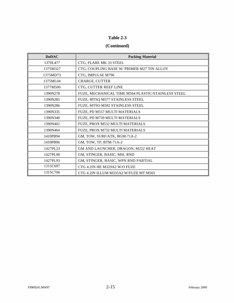
F9909241.MW97 2-15 February 2000
Table 2-3
(Continued)
DoDAC Packing Material
1370L477 CTG, FLARE MK 33 STEEL
1375M327 CTG, COUPLING BASE W/ PRIMER M27 TIN ALLOY
1375MD73 CTG, IMPULSE M796
1375ML04 CHARGE, CUTTER
1377M500 CTG, CUTTER REEF LINE
1390N278 FUZE, MECHANICAL TIME M564 PLASTIC/STAINLESS STEEL
1390N285 FUZE, MTSQ M577 STAINLESS STEEL
1390N286 FUZE, MTSO M582 STAINLESS STEEL
1390N335 FUZE, PD M557 MULTI MATERIALS
1390N340 FUZE, PD M739 MULTI MATERIALS
1390N402 FUZE, PROX M532 MULTI MATERIALS
1390N464 FUZE, PROX M732 MULTI MATERIALS
1410PB94 GM, TOW, SURF/ATK, BGM-71A-2
1410PB96 GM, TOW, TP, BTM-71A-2
1427PL23 GM AND LAUNCHER, DRAGON, M222 HEAT
1427PL90 GM, STINGER, BASIC, MSL RND
1427PL93 GM, STINGER, BASIC, WPN RND PARTIAL1315C697 CTG 4.2IN HE M329A2 W/O FUZE1315C706 CTG 4.2IN ILLUM M335A2 W/FUZE MT M565
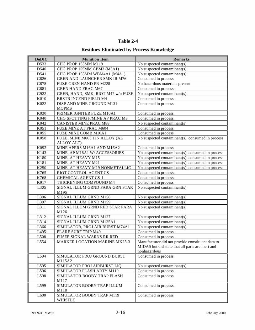
F9909241.MW97 2-16 February 2000
Table 2-4
Residues Eliminated by Process Knowledge
DoDIC Munition Item RemarksD533 CHG PROP 155MM M119 No suspected contaminant(s)D540 CHG PROP 155MM GBM3 (M3A1) No suspected contaminant(s)D541 CHG PROP 155MM WBM4A1 (M4A1) No suspected contaminant(s)G826 GREN AND LAUNCHER SMK IR M76 Consumed in processG878 FUZE GREN HAND PR M228 No hazardous materials presentG881 GREN HAND FRAG M67 Consumed in processG922 GREN, HAND, SMK, RIOT M47 w/o FUZE No suspected contaminant(s)K010 BRSTR INCEND FIELD M4 Consumed in processK022 DISP AND MINE GROUND M131
MOPMSConsumed in process
K030 PRIMER IGNITER FUZE M10A1 Consumed in processK040 CHG SPOTTING F/MINE AP PRAC M8 Consumed in processK042 CANISTER MINE PRAC M88 No suspected contaminant(s)K051 FUZE MINE AT PRAC M604 Consumed in processK055 FUZE MINE COMB M10A1 Consumed in processK058 FUZE, MINE M605 TIN ALLOY (AL
ALLOY ALT)No suspected contaminant(s), consumed in process
K092 MINE APERS M16A1 AND M16A2 Consumed in processK143 MINE, AP M18A1 W/ ACCESSORIES No suspected contaminant(s), consumed in processK180 MINE, AT HEAVY M15 No suspected contaminant(s), consumed in processK181 MINE, AT HEAVY M21 No suspected contaminant(s), consumed in processK250 MINE, AT HEAVY M19 NONMETALLIC No suspected contaminant(s), consumed in processK765 RIOT CONTROL AGENT CS Consumed in processK768 CHEMICAL AGENT CS-1 Consumed in processK917 THICKENING COMPOUND M4 Consumed in processL305 SIGNAL ILLUM GRND PARA GRN STAR
M195No suspected contaminant(s)
L306 SIGNAL ILLUM GRND M158 No suspected contaminant(s)L307 SIGNAL ILLUM GRND M159 No suspected contaminant(s)L311 SIGNAL ILLUM GRND RED STAR PARA
M126No suspected contaminant(s)
L312 SIGNAL ILLUM GRND M127 No suspected contaminant(s)L314 SIGNAL ILLUM GRND M125A1 No suspected contaminant(s)L366 SIMULATOR, PROJ AIR BURST M74A1 No suspected contaminant(s)L495 FLARE SURF TRIP M49 Consumed in processL508 FUSEE SIGNAL WARNS RR RED Consumed in processL554 MARKER LOCATION MARINE MK25-3 Manufacturer did not provide constituent data to
MIDAS but did state that all parts are inert andnonhazardous
L594 SIMULATOR PROJ GROUND BURSTM115A2
Consumed in process
L595 SIMULATOR PROJ AIRBURST LIQ No suspected contaminant(s)L596 SIMULATOR FLASH ARTY M110 Consumed in processL598 SIMULATOR BOOBY TRAP FLASH
M117Consumed in process
L599 SIMULATOR BOOBY TRAP ILLUMM118
Consumed in process
L600 SIMULATOR BOOBY TRAP M119WHISTLE
Consumed in process
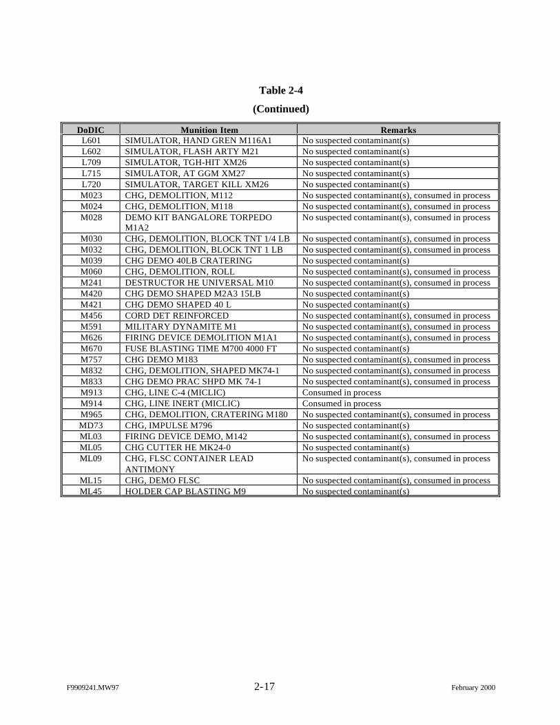
F9909241.MW97 2-17 February 2000
Table 2-4
(Continued)
DoDIC Munition Item RemarksL601 SIMULATOR, HAND GREN M116A1 No suspected contaminant(s)L602 SIMULATOR, FLASH ARTY M21 No suspected contaminant(s)L709 SIMULATOR, TGH-HIT XM26 No suspected contaminant(s)L715 SIMULATOR, AT GGM XM27 No suspected contaminant(s)L720 SIMULATOR, TARGET KILL XM26 No suspected contaminant(s)M023 CHG, DEMOLITION, M112 No suspected contaminant(s), consumed in processM024 CHG, DEMOLITION, M118 No suspected contaminant(s), consumed in processM028 DEMO KIT BANGALORE TORPEDO
M1A2No suspected contaminant(s), consumed in process
M030 CHG, DEMOLITION, BLOCK TNT 1/4 LB No suspected contaminant(s), consumed in processM032 CHG, DEMOLITION, BLOCK TNT 1 LB No suspected contaminant(s), consumed in processM039 CHG DEMO 40LB CRATERING No suspected contaminant(s)M060 CHG, DEMOLITION, ROLL No suspected contaminant(s), consumed in processM241 DESTRUCTOR HE UNIVERSAL M10 No suspected contaminant(s), consumed in processM420 CHG DEMO SHAPED M2A3 15LB No suspected contaminant(s)M421 CHG DEMO SHAPED 40 L No suspected contaminant(s)M456 CORD DET REINFORCED No suspected contaminant(s), consumed in processM591 MILITARY DYNAMITE M1 No suspected contaminant(s), consumed in processM626 FIRING DEVICE DEMOLITION M1A1 No suspected contaminant(s), consumed in processM670 FUSE BLASTING TIME M700 4000 FT No suspected contaminant(s)M757 CHG DEMO M183 No suspected contaminant(s), consumed in processM832 CHG, DEMOLITION, SHAPED MK74-1 No suspected contaminant(s), consumed in processM833 CHG DEMO PRAC SHPD MK 74-1 No suspected contaminant(s), consumed in processM913 CHG, LINE C-4 (MICLIC) Consumed in processM914 CHG, LINE INERT (MICLIC) Consumed in processM965 CHG, DEMOLITION, CRATERING M180 No suspected contaminant(s), consumed in processMD73 CHG, IMPULSE M796 No suspected contaminant(s)ML03 FIRING DEVICE DEMO, M142 No suspected contaminant(s), consumed in processML05 CHG CUTTER HE MK24-0 No suspected contaminant(s)ML09 CHG, FLSC CONTAINER LEAD
ANTIMONYNo suspected contaminant(s), consumed in process
ML15 CHG, DEMO FLSC No suspected contaminant(s), consumed in processML45 HOLDER CAP BLASTING M9 No suspected contaminant(s)
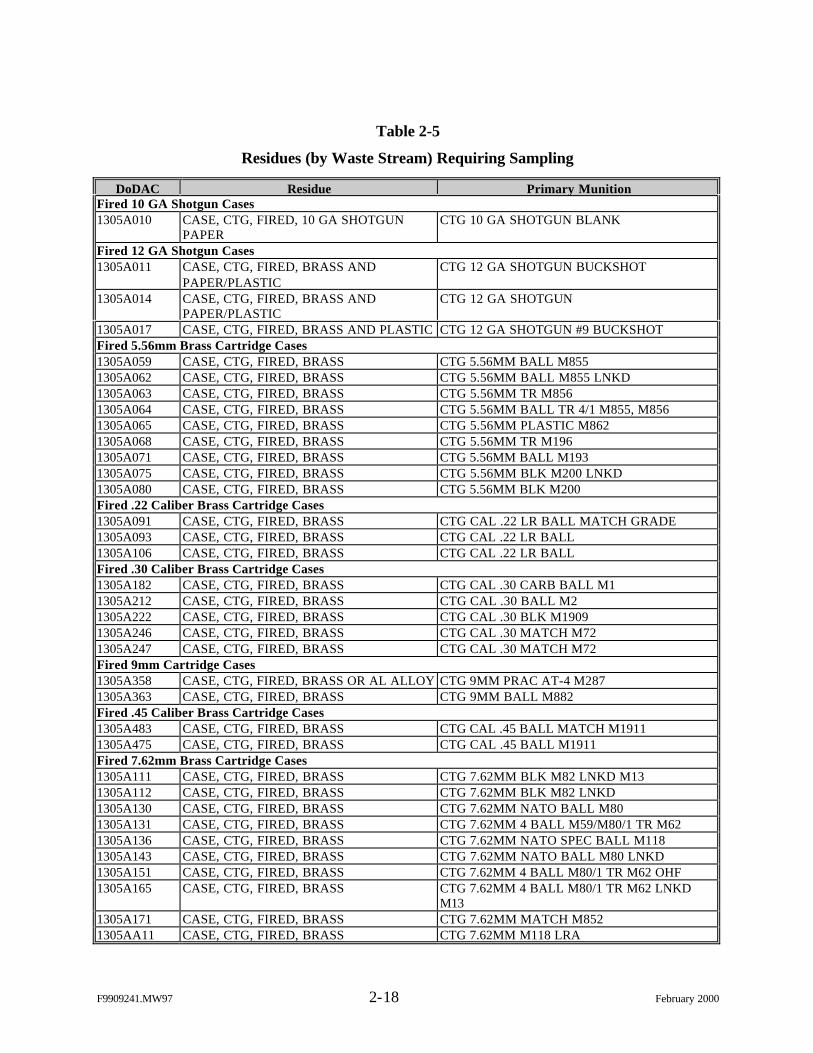
F9909241.MW97 2-18 February 2000
Table 2-5
Residues (by Waste Stream) Requiring Sampling
DoDAC Residue Primary MunitionFired 10 GA Shotgun Cases1305A010 CASE, CTG, FIRED, 10 GA SHOTGUN
PAPERCTG 10 GA SHOTGUN BLANK
Fired 12 GA Shotgun Cases1305A011 CASE, CTG, FIRED, BRASS AND
PAPER/PLASTICCTG 12 GA SHOTGUN BUCKSHOT
1305A014 CASE, CTG, FIRED, BRASS ANDPAPER/PLASTIC
CTG 12 GA SHOTGUN
1305A017 CASE, CTG, FIRED, BRASS AND PLASTIC CTG 12 GA SHOTGUN #9 BUCKSHOTFired 5.56mm Brass Cartridge Cases1305A059 CASE, CTG, FIRED, BRASS CTG 5.56MM BALL M8551305A062 CASE, CTG, FIRED, BRASS CTG 5.56MM BALL M855 LNKD1305A063 CASE, CTG, FIRED, BRASS CTG 5.56MM TR M8561305A064 CASE, CTG, FIRED, BRASS CTG 5.56MM BALL TR 4/1 M855, M8561305A065 CASE, CTG, FIRED, BRASS CTG 5.56MM PLASTIC M8621305A068 CASE, CTG, FIRED, BRASS CTG 5.56MM TR M1961305A071 CASE, CTG, FIRED, BRASS CTG 5.56MM BALL M1931305A075 CASE, CTG, FIRED, BRASS CTG 5.56MM BLK M200 LNKD1305A080 CASE, CTG, FIRED, BRASS CTG 5.56MM BLK M200Fired .22 Caliber Brass Cartridge Cases1305A091 CASE, CTG, FIRED, BRASS CTG CAL .22 LR BALL MATCH GRADE1305A093 CASE, CTG, FIRED, BRASS CTG CAL .22 LR BALL1305A106 CASE, CTG, FIRED, BRASS CTG CAL .22 LR BALLFired .30 Caliber Brass Cartridge Cases1305A182 CASE, CTG, FIRED, BRASS CTG CAL .30 CARB BALL M11305A212 CASE, CTG, FIRED, BRASS CTG CAL .30 BALL M21305A222 CASE, CTG, FIRED, BRASS CTG CAL .30 BLK M19091305A246 CASE, CTG, FIRED, BRASS CTG CAL .30 MATCH M721305A247 CASE, CTG, FIRED, BRASS CTG CAL .30 MATCH M72Fired 9mm Cartridge Cases1305A358 CASE, CTG, FIRED, BRASS OR AL ALLOY CTG 9MM PRAC AT-4 M2871305A363 CASE, CTG, FIRED, BRASS CTG 9MM BALL M882Fired .45 Caliber Brass Cartridge Cases1305A483 CASE, CTG, FIRED, BRASS CTG CAL .45 BALL MATCH M19111305A475 CASE, CTG, FIRED, BRASS CTG CAL .45 BALL M1911Fired 7.62mm Brass Cartridge Cases1305A111 CASE, CTG, FIRED, BRASS CTG 7.62MM BLK M82 LNKD M131305A112 CASE, CTG, FIRED, BRASS CTG 7.62MM BLK M82 LNKD1305A130 CASE, CTG, FIRED, BRASS CTG 7.62MM NATO BALL M801305A131 CASE, CTG, FIRED, BRASS CTG 7.62MM 4 BALL M59/M80/1 TR M621305A136 CASE, CTG, FIRED, BRASS CTG 7.62MM NATO SPEC BALL M1181305A143 CASE, CTG, FIRED, BRASS CTG 7.62MM NATO BALL M80 LNKD1305A151 CASE, CTG, FIRED, BRASS CTG 7.62MM 4 BALL M80/1 TR M62 OHF1305A165 CASE, CTG, FIRED, BRASS CTG 7.62MM 4 BALL M80/1 TR M62 LNKD
M131305A171 CASE, CTG, FIRED, BRASS CTG 7.62MM MATCH M8521305AA11 CASE, CTG, FIRED, BRASS CTG 7.62MM M118 LRA
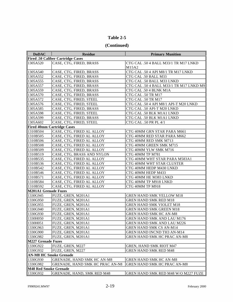
F9909241.MW97 2-19 February 2000
Table 2-5
(Continued)
DoDAC Residue Primary MunitionFired .50 Caliber Cartridge Cases1305A520 CASE, CTG, FIRED, BRASS CTG CAL .50 4 BALL M33/1 TR M17 LNKD
M15A21305A540 CASE, CTG, FIRED, BRASS CTG CAL .50 4 API M8/1 TR M17 LNKD1305A552 CASE, CTG, FIRED, BRASS CTG CAL .50 BALL M331305A555 CASE, CTG, FIRED, BRASS CTG CAL .50 BALL M33 LNKD1305A557 CASE, CTG, FIRED, BRASS CTG CAL .50 4 BALL M33/1 TR M17 LNKD M91305A559 CASE, CTG, FIRED, BRASS CTG CAL .50 4 BLNK M1A1305A570 CASE, CTG, FIRED, BRASS CTG CAL .50 TR M171305A572 CASE, CTG, FIRED, STEEL CTG CAL .50 TR M171305A576 CASE, CTG, FIRED, STEEL CTG CAL .50 4 API M8/1 API-T M20 LNKD1305A585 CASE, CTG, FIRED, BRASS CTG CAL .50 API-T M20 LNKD1305A598 CASE, CTG, FIRED, STEEL CTG CAL .50 BLK M1A1 LNKD1305A599 CASE, CTG, FIRED, BRASS CTG CAL .50 BLK M1A1 LNKD1305A602 CASE, CTG, FIRED, STEEL CTG CAL .50 PR PL 4/1Fired 40mm Cartridge Cases1310B504 CASE, CTG, FIRED AL ALLOY CTG 40MM GRN STAR PARA M6611310B505 CASE, CTG, FIRED AL ALLOY CTG 40MM RED STAR PARA M6621310B506 CASE, CTG, FIRED AL ALLOY CTG 40MM RED SMK M7131310B508 CASE, CTG, FIRED AL ALLOY CTG 40MM GREEN SMK M7151310B509 CASE, CTG, FIRED AL ALLOY CTG 40MM YLW SMK M7161310B519 CASE, CTG, BRASS AND NYLON CTG 40MM TP M7811310B535 CASE, CTG, FIRED AL ALLOY CTG 40MM WHT STAR PARA M583A11310B536 CASE, CTG, FIRED AL ALLOY CTG 40MM WHT STAR CLUSTER1310B542 CASE, CTG, FIRED AL ALLOY CTG 40MM HEDP M430 LNKD1310B546 CASE, CTG, FIRED AL ALLOY CTG 40MM HEDP M4331310B571 CASE, CTG, FIRED AL ALLOY CTG 40MM HE M383 LNKD1310B584 CASE, CTG, FIRED AL ALLOY CTG 40MM TP M918 LNKD1310B592 CASE, CTG, FIRED AL ALLOY CTG 40MM TP M918M201A1 Grenade Fuzes1330G945 FUZE, GREN, M201A1 GREN HAND SMK YELLOW M181330G950 FUZE, GREN, M201A1 GREN HAND SMK RED M181330G955 FUZE, GREN, M201A1 GREN HAND SMK VIOLET M181330G940 FUZE, GREN, M201A1 GREN HAND SMK GREEN M181330G930 FUZE, GREN, M201A1 GREN HAND SMK HC AN-M81330H050 FUZE, GREN, M201A1 GREN HAND SMK AND LAU M1761330H051 FUZE, GREN, M201A1 GREN HAND SMK AND LAU M2261330G963 FUZE, GREN, M201A1 GREN HAND SMK CS AN-M141330G900 FUZE, GREN, M201A1 GREN HAND INCND TH3 AN-M141330G982 FUZE, GREN, M201A1 GREN HAND SMK HC PRAC AN-M8M227 Grenade Fuzes1330G922 FUZE, GREN, M227 GREN, HAND SMK RIOT M471330G932 FUZE, GREN, M227 GREN HAND SMK RED M48AN-M8 HC Smoke Grenade1330G930 GRENADE, HAND SMK HC AN-M8 GREN HAND SMK HC AN-M81330G982 GRENADE, HAND SMK HC PRAC AN-N8 GREN HAND SMK HC PRAC AN-M8M48 Red Smoke Grenade1330G932 GRENADE, HAND, SMK RED M48 GREN HAND SMK RED M48 W/O M227 FUZE
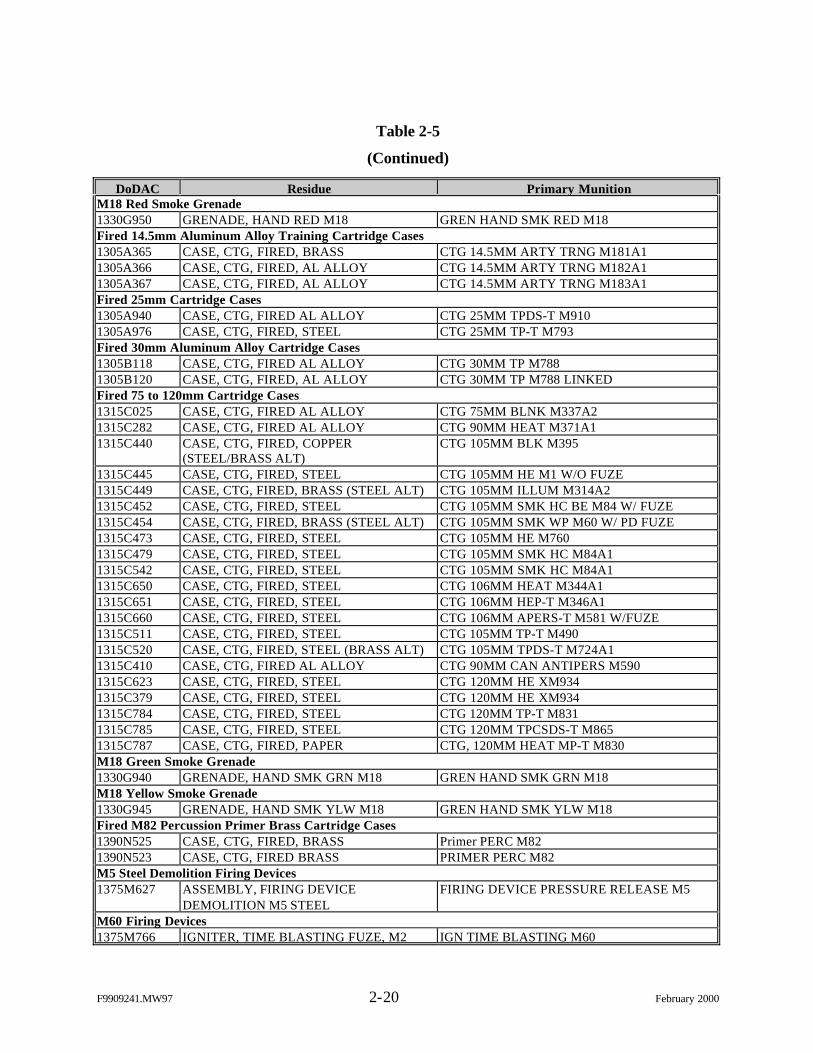
F9909241.MW97 2-20 February 2000
Table 2-5
(Continued)
DoDAC Residue Primary MunitionM18 Red Smoke Grenade1330G950 GRENADE, HAND RED M18 GREN HAND SMK RED M18Fired 14.5mm Aluminum Alloy Training Cartridge Cases1305A365 CASE, CTG, FIRED, BRASS CTG 14.5MM ARTY TRNG M181A11305A366 CASE, CTG, FIRED, AL ALLOY CTG 14.5MM ARTY TRNG M182A11305A367 CASE, CTG, FIRED, AL ALLOY CTG 14.5MM ARTY TRNG M183A1Fired 25mm Cartridge Cases1305A940 CASE, CTG, FIRED AL ALLOY CTG 25MM TPDS-T M9101305A976 CASE, CTG, FIRED, STEEL CTG 25MM TP-T M793Fired 30mm Aluminum Alloy Cartridge Cases1305B118 CASE, CTG, FIRED AL ALLOY CTG 30MM TP M7881305B120 CASE, CTG, FIRED, AL ALLOY CTG 30MM TP M788 LINKEDFired 75 to 120mm Cartridge Cases1315C025 CASE, CTG, FIRED AL ALLOY CTG 75MM BLNK M337A21315C282 CASE, CTG, FIRED AL ALLOY CTG 90MM HEAT M371A11315C440 CASE, CTG, FIRED, COPPER
(STEEL/BRASS ALT)CTG 105MM BLK M395
1315C445 CASE, CTG, FIRED, STEEL CTG 105MM HE M1 W/O FUZE1315C449 CASE, CTG, FIRED, BRASS (STEEL ALT) CTG 105MM ILLUM M314A21315C452 CASE, CTG, FIRED, STEEL CTG 105MM SMK HC BE M84 W/ FUZE1315C454 CASE, CTG, FIRED, BRASS (STEEL ALT) CTG 105MM SMK WP M60 W/ PD FUZE1315C473 CASE, CTG, FIRED, STEEL CTG 105MM HE M7601315C479 CASE, CTG, FIRED, STEEL CTG 105MM SMK HC M84A11315C542 CASE, CTG, FIRED, STEEL CTG 105MM SMK HC M84A11315C650 CASE, CTG, FIRED, STEEL CTG 106MM HEAT M344A11315C651 CASE, CTG, FIRED, STEEL CTG 106MM HEP-T M346A11315C660 CASE, CTG, FIRED, STEEL CTG 106MM APERS-T M581 W/FUZE1315C511 CASE, CTG, FIRED, STEEL CTG 105MM TP-T M4901315C520 CASE, CTG, FIRED, STEEL (BRASS ALT) CTG 105MM TPDS-T M724A11315C410 CASE, CTG, FIRED AL ALLOY CTG 90MM CAN ANTIPERS M5901315C623 CASE, CTG, FIRED, STEEL CTG 120MM HE XM9341315C379 CASE, CTG, FIRED, STEEL CTG 120MM HE XM9341315C784 CASE, CTG, FIRED, STEEL CTG 120MM TP-T M8311315C785 CASE, CTG, FIRED, STEEL CTG 120MM TPCSDS-T M8651315C787 CASE, CTG, FIRED, PAPER CTG, 120MM HEAT MP-T M830M18 Green Smoke Grenade1330G940 GRENADE, HAND SMK GRN M18 GREN HAND SMK GRN M18M18 Yellow Smoke Grenade1330G945 GRENADE, HAND SMK YLW M18 GREN HAND SMK YLW M18Fired M82 Percussion Primer Brass Cartridge Cases1390N525 CASE, CTG, FIRED, BRASS Primer PERC M821390N523 CASE, CTG, FIRED BRASS PRIMER PERC M82M5 Steel Demolition Firing Devices1375M627 ASSEMBLY, FIRING DEVICE
DEMOLITION M5 STEELFIRING DEVICE PRESSURE RELEASE M5
M60 Firing Devices1375M766 IGNITER, TIME BLASTING FUZE, M2 IGN TIME BLASTING M60
F9909241.MW97 2-21 February 2000
Table 2-5
(Continued)
DoDAC Residue Primary MunitionM81 Firing Devices1375MN08 IGNITER DEVICE PLASTIC IGNITER TIME BLASTING FUSE M81M6 Electric Blasting Cap1375M130 CAP, BLASTING ELECT M6 ASSY CAP BLASTING ELECT M6M7 Nonelectric Blasting Cap1375M131 CAP, BLASTING NONELECT M7 ASSY CAP BLASTING NONELECT M7M7A3 CS Riot Control Hand Grenade1330G963 GREN, HAND RIOT CS M7A3 GREN, HAND RIOT M7A3TH3 AN-M14 Incendiary Hand Grenade1330G900 GREN, HAND, INCEND, TH3 AN-M14 GREN, HAND, INCEND, TH AN-M14 W/O
FUZEM1 HC 155mm Smoke Canisters1315D445 155MM SMK CANISTER CANISTER 155MM SMK HC M1M11 Nonelectric Blasting Cap (Donor Charge)1375ML47 SHOCK TUBE, SURLYN POLYETHYLENE
W/DETONATORSHOCK TUBE, 30 FT, SURLYNPOLYETHYLENE W/ DETONATOR
1375MN36 SHOCK TUBE, SURLYN POLYETHYLENEW/DETONATOR
SHOCK TUBE, 30 FT, SURLYNPOLYETHYLENE W/ DETONATOR
M12 and M13 Nonelectric Blasting Cap (Primary Charge)1375MN02 SHOCK TUBE, SURLYN POLYETHYLENE
W/DETONATORSHOCK TUBE, 500 FT, SURLYNPOLYETHYLENE W/DETONATOR
1375MN35 SHOCK TUBE, SURLYN POLYETHYLENEW/DETONATOR
SHOCK TUBE, 500 FT, SURLYNPOLYETHYLENE W/DETONATOR
1375MN03 SHOCK TUBE, SURLYN POLYETHYLENEW/DETONATOR
SHOCK TUBE, 1000 FT, SURLYNPOLYETHYLENE W/DETONATOR
M14 Nonelectric Blasting Cap (Time Fuse)1375MN06 DETONATOR, TIME FUSE
CLOTH/PLASTICDETONATOR, 7.5 FT TIME FUSECLOTH/PLASTIC
1375MN37 DETONATOR, TIME FUSECLOTH/PLASTIC
DETONATOR, 7.5 FT TIME FUSECLOTH/PLASTIC
M15 Nonelectric Delay Blasting Cap1375MN07 DETONATOR, TIME FUSE
CLOTH/PLASTICDETONATOR, 70 FT TIME FUSECLOTH/PLASTIC
1375MN38 DETONATOR, TIME FUSECLOTH/PLASTIC
DETONATOR, 70 FT TIME FUSECLOTH/PLASTIC
Fired 20mm Steel Cartridge Cases1305A896 CASE, CTG, FIRED, STEEL CTG, 20MM TP M55 A2/1 TP-T M220 LINKED
M14A225.4mm Cartridge Cases1305A960 CASE, CTG, FIRED, AL ALLOY CTG, 25.4MM DECOY M839M4A2 HC Floating Smoke Pot1330K867 SMOKE POT M4A2 FLOATING TYPE SMK POT FLOATING TYPE HC M4A2ABC-M5 HC Smoke Pot1330K866 SMOKE POT M5 GROUND TYPE SMK POT HC 30 LB ABCM5M18 Violet Smoke Grenade1330G955 GRENADE, HAND SMK VIOLET M18 GREN HAND SMK VIOLET M18Personal Distress Flare Kit1345L116 SIGNAL KIT, PERSONAL DISTRESS RED
XM185 A/P92 S-5ASIGNAL KIT, PERSONAL DISTRESS REDXM185 A/P92 S-5A
F9909241.MW97 2-22 February 2000
The decision rules listed above present RCRA hazardous waste determination and
identification of UHCs for characteristically hazardous items as the primary characterization
requirements. In addition to these regulatory driven data needs, data are also needed to address
concerns associated with CERCLA liability and downstream processors, as well as to ensure
appropriate management/processing practices are implemented to take advantage of the RCRA
exclusion and exemption. Table 2-5 provides a summary of the characterization requirements,
methods for achieving the requirements, and applicable regulatory limits/action levels. Table 2-6
indicates that contaminants of interest include metals, semivolatile organic compounds (SVOCs),
and explosives.
Toxicity Characteristic Leaching Procedure (TCLP) extraction and metals
analysis (SW-6010/7000+) will be performed for all TCLP metals suspected to be present in the
scrap item. Since the entire scrap item represents a single waste stream, the material submitted
for extraction shall consist of a homogenized sample representing the entire item. The TCLP
metal results will be compared to TCLP limits and universal treatment standards, as required.
These data are also useful to downstream processors in the event that the item is recycled.
Hazardous constituents detected in scrap items will also be useful in evaluating the need for
additional management/handling procedures.
To address toxicity for SVOCs, the following approach is taken:
1. Perform total SVOC analysis (SW-8270).
2. List all SVOCs detected in the total SVOC analysis as potential UHCs.
3. Compare total SVOC results to the maximum theoretical leaching limit (20times the respective TCLP limit) to determine whether TCLP analysis iswarranted for certain SVOCs.
4. Perform TCLP for SVOC analysis, if applicable.
5. If the item is determined to be RCRA hazardous, compare SVOCs detected inthe total SVOC analysis to the universal treatment standards in order toidentify UHCs.
F9909241.MW97 2-23 February 2000
Table 2-6
Method to Achieve Characterization Requirements
CharacterizationRequirement Method
ApplicableLimit/Threshold
Hazardous waste determination:Evaluate ignitabilityof item
Spent munitions residues certified inert by trained personnel arenot “capable under standard temperature and pressure of causingfire through friction, absorption of moisture or spontaneouschemical changes and, when ignited, burn so vigorously andpersistently that a hazard is created.”a
Not applicable
Evaluate corrosivityof item
Spent munitions residues considered in this study are not“aqueous or liquid.”b
Not applicable
Evaluate reactivity ofitem
Spent munitions residues certified inert by trained personnel donot exhibit any of the properties listed for reactivity in 40 CFR261.23.
Not applicable
Evaluate toxicity ofitem:Metals
1. Process knowledge information: lack of RCRA TCLPmetals in item.
2. Sampling and analysis: perform TCLP extraction andmetals analysis (SW-6010/7000+) for suspected metals.
1. Not applicable2. Applicable TCLP
limits
Semivolatile OrganicCompounds (SVOCs)
1. Process knowledge information: lack of RCRA TCLPSVOCs in item.
2. Sampling and analysis: perform SVOC analysis (SW-8270)for suspected compounds and compare to diluted TCLPlimits.c
1. Not applicable2. Maximum theoretical
leaching limit
Volatile OrganicCompounds (VOCs)/pesticides/herbicides/polychlorinatedbiphenyls (PCBs)
Process knowledge information: Volatile compounds areconsumed in process and lack of pesticides/herbicides/PCBs initem.
Not applicable
Identify UHCs:Metals Sampling and analysis: metals identified in TCLP analysis. Universal treatment
standards (40 CFR 268.48)SVOCs Sampling and analysis: conduct SVOC analysis (SW-8270). Universal treatment
standards (40 CFR 268.48)VOCs/pesticides/herbicides/PCBs
Process knowledge information: Volatile compounds areconsumed in process and lack of pesticides/herbicides/PCBs initem.
Not applicable
Secondary characterization requirements:Evaluate additionalmanagement/handlingrequirements
Sampling and analysis: provide data obtained for hazardouswaste determination and identification of UHCs, if applicable,and perform analysis to determine the presence/level ofexplosive compounds (Method 8330).
Qualitative.d
F9909241.MW97 2-24 February 2000
Table 2-6
(Continued)
CharacterizationRequirement Method
ApplicableLimit/Threshold
Provide assurance fordownstreamprocessors
Sampling and analysis: provide data obtained for hazardouswaste determination and identification of UHCs, if applicable,and perform analysis to determine the presence/level ofexplosive compounds (Method 8330).
Qualitative.d
a40 CFR 261.21.b40 CFR 261.22.cSVOCs present in the waste stream must be compared to universal treatment standards (40 CFR 268.48) by total analysis.Therefore, standard SVOC analysis (not leached) will be conducted and results will be compared to the universal treatmentstandards limits and 20 times (conservatively assuming 100% leach) the applicable TCLP limit. Waste streams with SVOCsdetected above 20 times the applicable TCLP limit will be resubmitted for TCLP analysis.dIdentify the presence of RCRA hazardous constituents, UHCs, and explosive compounds. Recommendations for additionalmanagement/processing practices will be based on the presence of contaminants (leachable metals, leachable SVOCs, and/orenergetic compounds) and the physical state of the range scrap item (high/moderate/low potential to release contaminants).
Conducting the total SVOC analysis prior to TCLP will also provide a more
sensitive test for SVOCs since they are not expected to be present in high concentrations as
compared to metals (i.e., a diluted TCLP sample result may indicate non-detect for SVOC in the
diluted sample extract, but the total analysis may be able to detect the presence of SVOCs in an
undiluted sample). This sample scheme will also provide useful data to downstream processors
in the event the item is recycled, as well as provide data for evaluating the need for additional
management/handling procedures.
Spent munitions residues certified inert by trained personnel do not exhibit any of
the properties listed for RCRA reactivity in 40 CFR 261.23. For recycled items, however,
characterization is required for low levels of explosives/energetics in order to provide data to
downstream users and to assess the need for additional management/handling procedures to
understand and minimize CERCLA liabilities. There are no RCRA or other waste classification
limits published for energetic compounds except for dinitrotoluene (DNT), which will be
detected by the traditional SVOC analysis provided above. Instead, characterization for energetic
compounds will be used as a secondary data requirement to qualitatively address the DQOs. The
metals, SVOCs, and energetic analyses combine to provide downstream users a complete listing
of constituents of concern associated with the scrap item. Samples will be submitted for analysis
F9909241.MW97 2-25 February 2000
by EPA Method 8330 for nitroaromatics and the method will be modified to detect and report
nitrate esters including pentaerythritol tetranitrate (PETN) and nitroglycerin.
2.6 Specify Limits on Decision Errors
The key decision to be addressed by sampling and analysis of range residues is
whether the item is a RCRA toxic hazardous waste. TCLP analysis will be conducted and the
results will be compared to the TCLP limits. The sampling design for this effort will follow
guidance contained in SW-846 methodology. The contaminants of concern will not be
considered to be present in the item at a hazardous level if the upper limit of the confidence
interval is less than the applicable TCLP limit. The factors that define the limits of the decision
error are provided below:
CI = 0 +/- t.20(sx)
Where:CI = 80% Confidence interval,0 = Mean of measurement generated by sample (sample mean),t.20 = Student’s “t” value for a two-tailed confidence interval and a
probability of 0.20,sx = Standard error (also standard deviation of mean) of sample.
Limits for analytical accuracy and precision are specified within the prescribed
EPA analytical methods and will be evaluated during review of the data. The sampling and
analysis plan for this effort will summarize the quality assurance (QA)/quality control (QC)
limits associated with each analytical method.
2.7 Optimize Design
The SW-846 methodology referenced above requires that the sampling design
achieve sufficient degree of accuracy and precision to reliably estimate the level of contaminants
of concern for an item for the purpose of comparing those levels to the TCLP limits.
F9909241.MW97 2-26 February 2000
Optimization of the general characterization scheme and approach for specific waste streams is
discussed in Sections 2.7.1 and 2.7.2, respectively.
2.7.1 General Characterization Scheme
Sampling accuracy for this study will be addressed by developing and following
sample collection procedures that are designed to minimize the introduction of errors to the
associated analysis. Sampling precision is addressed by collecting the appropriate number of
samples. Following the SW-846 methodology for characterizing solid waste, the appropriate
number of samples is the least number of samples needed to demonstrate that the upper limit of
the confidence interval for the mean is less than the applicable TCLP limit. The appropriate
number of samples is calculated from an approximation of the mean and variance of the sample
set based on limited previous sampling. In this case, the follow equation is employed:
n = (t.202 * s2)/(TCLP limit – 0)2
Where:n = Appropriate number of samples to collect to support evaluation,t.20 = Student’s “t” value based on the number of samples taken to date,s2 = Variance of sample based on the number of samples taken to date,0 = Mean of measurements based on the number of samples taken to date.
However, there are no data on most of the range residue items to perform this
estimate. Instead, best judgement must be used to determine the number of samples to be taken.
The mean, confidence interval, and other parameters of the sample set may then be calculated
and evaluated based on the data generated. Additional samples may be submitted for laboratory
analysis, if necessary. In order to determine the number of samples to collect for each item, it is
recommended that the relationship between the Student’s “t2” value used in the equation above
and the “number of samples collected” be evaluated (Figure 2-2). Review of this relationship
reveals that the Student’s “t” statistic becomes asymptotic as the number of samples increases.
The optimum number of samples to collect based on this relationship is approximately eight
samples.
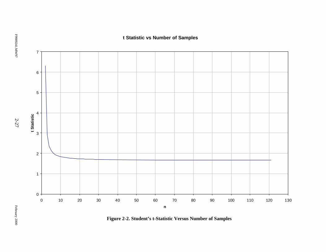
F9909241.MW
972-27
February 2000
Figure 2-2. Student’s t-Statistic Versus Number of Samples
t Statistic vs Number of Samples
0
1
2
3
4
5
6
7
0 10 20 30 40 50 60 70 80 90 100 110 120 130
n
t S
tati
stic
F9909241.MW97 2-28 February 2000
To further optimize the sampling design, a minimum of three samples will be
collected initially. The additional samples will be held and submitted for analysis after evaluating
the upper confidence limits to applicable TCLP limits. This methodology will reduce cost, while
still achieving the study objectives. Note that samples submitted for TCLP analysis will consist
of the entire scrap item. This will be achieved by milling the scrap items down to sizes that meet
TCLP extraction specifications and homogenizing that material prior to obtaining the laboratory
sample.
To provide a statistically based estimation of the average concentration of UHCs
and explosive compounds, a minimum of three samples will also be collected from each item for
this purpose.
2.7.2 Characterization Approach for Specific Waste Streams
Waste streams or scrap items (Table 2-4) within the inventory that have only one
DoDAC associated with them will be characterized as described in Section 2.7.1. However, the
characterization of waste streams that have multiple DoDACs will be optimized to focus on the
most conservative DoDAC. This approach is crucial in conserving limited project resources
given the quantity of munitions items associated with the scrap items requiring characterization.
As discussed previously, the amount and type of constituents/materials will be
reviewed for all DoDACs within a waste stream to ensure there are no significant variations.
This information will also be used to determine which munitions item (DoDAC) within the waste
stream represents the most conservative choice for characterization. This information will be
presented in the following three ways:
Ø Scrap components and materials,
Ø Composition of reactive materials in the munitions item, and
Ø Maximum theoretical leaching limit evaluation.
A discussion of each factor is provided below.
F9909241.MW97 2-29 February 2000
2.7.2.1 Scrap components and materials
The composition of the inert material(s) of the range scrap item, such as the case,
primer cup, anvil, etc., may consist of or contain metal and/or organic compounds that are listed
as constituents of concern for this characterization. If these components are determined to be
significant to the characterization, residual material(s) should be consistent among the waste
streams with multiple DoDACs. The presence and concentration of contaminants of concern in
scrap components and materials will also influence the selection of the most conservative item
within the waste stream for sampling and analysis. A description of all significant materials will
be provided for each waste stream.
2.7.2.2 Composition of reactive materials associated with the munitions items
Many of the contaminants (heavy metals, organic compounds, explosive
residuals) suspected to be associated with range scrap items are the result of a small amount of
the reactive components remaining on the item after use. The chemical makeup of the primers,
propellants, etc., used in the munitions item and associated with the range scrap item must be
consistent among the DoDACs within a waste stream with regard to the primary contaminants of
concern. This information is also useful in determining which item in the waste stream represents
the most conservative choice, if applicable, for sampling and analysis. For instance, all items
within a waste stream may have the same constituent listing in their primer mix, but one item has
a slightly greater amount of lead-containing constituents and represents the most conservative
choice for sampling and analysis to represent the waste stream.
2.7.2.3 Maximum theoretical leaching limit evaluation
Review of the scrap item material composition and reactive components of the
munitions item will identify the potential for contaminants of concern to be present. This
information, together with the weight of the scrap item, provides sufficient data to determine the
maximum theoretical leaching level for RCRA toxic compounds present in a particular item. The
first use of this evaluation is to determine whether sampling and analysis is required to make the
F9909241.MW97 2-30 February 2000
hazardous waste determination for a particular item. For example, the following steps
demonstrate how this data may be used to determine whether sampling and analysis is required
to determine whether an item will fail (exceed) the TCLP limit for lead (5 mg/L):
1. Determine the overall weight of the range scrap item.
2. Determine the combined weight of lead-containing constituents and materials.
3. Calculate the percent weight of lead per overall weight of item.
4. The TCLP maximum theoretical leaching limit for lead in a sample is 100parts per million (ppm) (20 x 5 mg/L), assuming 100% leaching and a methoddilution of 20. This value (100 ppm) expressed as a percentage is 0.01%.
5. If the percent weight of lead to overall weight of item is less than 0.01%, therange scrap item could not theoretically fail TCLP for lead (i.e., even if 100%of the lead remained on/in the scrap item and leaches during testing, there isnot enough lead present to exceed the corresponding TCLP limit).
The second use of this data is to determine which DoDAC within a waste stream
has the highest potential concentration of contaminants of concern. The maximum theoretical
leaching limit evaluation takes into consideration all the factors discussed above (the maximum
potential amount of a contaminant of concern present in scrap components/materials,
composition of reactive materials, and the weight of the item) and provides a method of
determining which DoDAC within a waste stream represents the most conservative choice for
characterization.
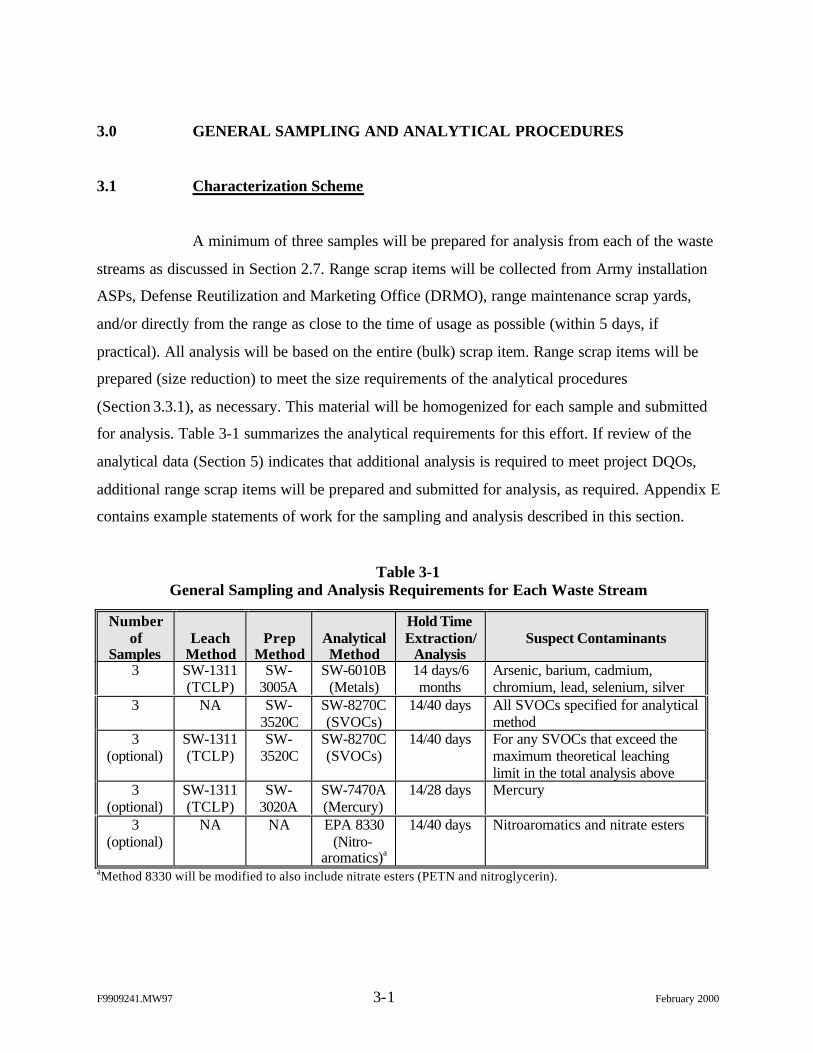
F9909241.MW97 3-1 February 2000
3.0 GENERAL SAMPLING AND ANALYTICAL PROCEDURES
3.1 Characterization Scheme
A minimum of three samples will be prepared for analysis from each of the waste
streams as discussed in Section 2.7. Range scrap items will be collected from Army installation
ASPs, Defense Reutilization and Marketing Office (DRMO), range maintenance scrap yards,
and/or directly from the range as close to the time of usage as possible (within 5 days, if
practical). All analysis will be based on the entire (bulk) scrap item. Range scrap items will be
prepared (size reduction) to meet the size requirements of the analytical procedures
(Section 3.3.1), as necessary. This material will be homogenized for each sample and submitted
for analysis. Table 3-1 summarizes the analytical requirements for this effort. If review of the
analytical data (Section 5) indicates that additional analysis is required to meet project DQOs,
additional range scrap items will be prepared and submitted for analysis, as required. Appendix E
contains example statements of work for the sampling and analysis described in this section.
Table 3-1General Sampling and Analysis Requirements for Each Waste Stream
Numberof
SamplesLeach
MethodPrep
MethodAnalyticalMethod
Hold TimeExtraction/
AnalysisSuspect Contaminants
3 SW-1311(TCLP)
SW-3005A
SW-6010B(Metals)
14 days/6months
Arsenic, barium, cadmium,chromium, lead, selenium, silver
3 NA SW-3520C
SW-8270C(SVOCs)
14/40 days All SVOCs specified for analyticalmethod
3(optional)
SW-1311(TCLP)
SW-3520C
SW-8270C(SVOCs)
14/40 days For any SVOCs that exceed themaximum theoretical leachinglimit in the total analysis above
3(optional)
SW-1311(TCLP)
SW-3020A
SW-7470A(Mercury)
14/28 days Mercury
3(optional)
NA NA EPA 8330(Nitro-
aromatics)a
14/40 days Nitroaromatics and nitrate esters
aMethod 8330 will be modified to also include nitrate esters (PETN and nitroglycerin).
F9909241.MW97 3-2 February 2000
3.2 Sample Collection Procedures
The sample collection procedures presented in this section apply to collection of
range scrap items for submittal to the sample preparation laboratory (Section 3.3).
3.2.1 Sample Collection
3.2.1.1 Sample collection performed by the project team
Range scrap items targeted for sampling may be collected from various Army
installations across the country based on the availability of the item. Range scrap items stored at
the ASP, DRMO, or other residue yard may be accumulated over various periods of time. In lieu
of designing an extensive sampling approach that would account for the variability of item
storage, this sampling effort will attempt to collect residues as close to the time of usage as
possible. This approach will ensure that characterization of the range scrap items is consistent
and the most conservative scenario.
The range scrap items will be collected, processed, and analyzed in an effort to
meet the holding time requirements listed in Table 3-1. Range scrap items will be collected
within 5 days from the date of usage to ensure the minimum holding time requirement (14 days)
is met. Variances from the holding time requirements may be granted for items that are difficult
to obtain due to the infrequency of use and will be evaluated on a case-by-case basis. After
collecting the range scrap items, the project team will proceed to follow the requirements stated
in Sections 3.2.2 through 3.2.8.
3.2.1.2 Sample collection performed by others
Sample collection may also be performed by other organizations and provided to
the project team for characterization. The project team will coordinate with the other
organization to prepare a listing of the range scrap items to be collected for characterization and
the required quantities. The other organization must collect the range scrap items in a timely
F9909241.MW97 3-3 February 2000
manner as stated in Section 3.2.1.1. The range scrap items shall be collected and shipped to the
project team within 5 days of the date of usage. The sampling procedure is outlined below:
1. Don a new pair of disposable gloves between each type of range scrapcollected.
2. Obtain/collect the range scrap items (specific items and quantities coordinatedwith the project team) as close to the date of usage as possible (refer toSection 3.2.1.1).
3. Perform “inert certification” (responsible organization) and retain a copy ofthe certification to accompany the samples.
4. Record the information requested on the Sample Collection Record providedin Appendix B.
5. Individually containerize (refer to Section 3.2.4) each range scrap item at thetime of collection to prevent the loss of materials associated with the item.The project team may provide containers, sample labels, chain-of-custody(COC) records, sample seals, and/or sample coolers (shipping containers), ifnecessary.
6. Assign a sample identifier to each item by listing the DoD Item Code(DoDIC) of the item followed by an alphabetical code “A” through “Z” (forexample: samples for the M18 red hand smoke grenade, DoDAC 1330G950,would have sample identifiers G950A, G950B, G950C, G950D, etc.) or asdirected by the project team.
7. Label each containerized item with the sample identifier, date and time ofcollection, and sampler initials.
8. Place containerized samples in shipping coolers (refer to Section 3.2.4) andcomplete a shipping waybill for each cooler.
9. Prepare a COC record for each shipping container (refer to Section 3.2.7).
10. Include a copy of the corresponding COC record and “inert certification” ineach shipping container and affix a sample seal to each container (refer toSection 3.2.6).
11. Retain a copy of COC record, Sample Collection Record, “inert certification,”shipping waybill, and any other pertinent documentation for the files.
12. Ship the sample coolers to a location specified by the project team.
F9909241.MW97 3-4 February 2000
3.2.1.3 Health and Safety Precautions
The project team will be restricted to collecting range scrap items at the ASP,
DRMO, and/or range clearance/maintenance yard where these items have been certified inert.
Sampling personnel must be supervised/escorted at these locations and are not permitted to
collect samples directly from range areas. Therefore, sampling personnel will adhere to the
health and safety precautions prescribed by the local organization.
Other organizations collecting range scrap items for characterization should
follow their own standard procedures for collecting range residues and performing “inert
certification.”
A copy of the “inert certification” should be provided to and retained by each
organization that handles the samples. This may include the project team, other organizations
conducting sample collection, the sample preparation laboratory, and the analytical laboratory.
3.2.2 Field QA/QC Samples
Field QA samples are not required for this sampling effort. The sampling
procedures do not require the addition of preservatives, use of sampling equipment, or other
special sample management/handling techniques. Therefore, field QA samples, such as field
blanks, rinsate blanks, or trip blanks, are not required.
Since the general sampling approach for this effort consists of obtaining multiple
samples of the same type of scrap item, collection of additional QC samples (replicates) will not
be necessary to evaluate the representativeness of the sampling approach. However, laboratory
duplicates will be performed per the methods specified in Section 3.3.2. This data will determine
the representativeness of the laboratory sample aliquot used for analyses and variation of
concentration of constituents within the scrap item sample.
F9909241.MW97 3-5 February 2000
3.2.3 Sample Labeling and Handling
Samples will be labeled at the time of collection. The label will contain the
following information:
Ø Sample identifier,
Ø Date and time of collection, and
Ø Sampler initials.
This information may be written directly on the sample container or on a label affixed to the
container. Sample label information should be completed using indelible ink.
3.2.4 Sample and Shipping Containers
The range scrap items must be individually containerized at the time of collection
to prevent loss or mixing of materials. The following types of containment may be employed:
1. Double bag and seal the containers with standard paper bags or othercontainer (avoid using plastics due to SVOC contaminants) using quart, half-gallon, gallon, 20- x 20-in., 24- x 24-in., or other various sizes. The seal oropen end of the bags shall be folded and secured with tape.
2. For larger range scrap items (will not fit in 24- x 24-in. plastic baggie), clear6-mil plastic sheeting shall be used to wrap and enclose the item. Open edgesof the plastic sheeting shall be folded and secured with duct tape. If there areloose, fine materials associated with the scrap item, these materials shall beemptied into containers as described above and placed inside the plasticsheeting with the scrap item.
Standard food/beverage coolers designated solely for sample shipment shall be
used for shipping the range scrap samples collected for this effort. A copy of the COC record,
shipping waybill, and “inert certification” shall be included in each shipping container. The
contents of the shipping container should be specified as “environmental samples.”
F9909241.MW97 3-6 February 2000
3.2.5 Sample Preservation and Storage
It is not expected that the scrap items will undergo physical, biological, and/or
chemical changes during sample handling due to their solid and stable nature. Consequently, no
preservation or special storage techniques will be employed. The most likely cause of sample
degradation is loss of solid materials from the samples, which is addressed in Section 3.2.4.
3.2.6 Sample Seals
Sample seals are used to preserve the integrity of the sample from the time it is
collected until it is opened in the laboratory. Gummed paper or plastic is used as official sample
seals. These seals will be applied to the outside of shipping packages.
3.2.7 Chain-of-Custody Record
All field samples submitted for sample preparation will be documented on a
standard COC form. If samples are hand delivered, the sampler, the courier (if other than the
sampler), and the receiver will sign the form. If samples are shipped via an overnight express
service, the number of the waybill will be substituted for the receiver signature. The receiver
must still sign the COC to acknowledge receipt at the sample preparation location.
The COC will include the following minimum information:
Ø Place of collection (sample identification),
Ø Data and time of collection,
Ø Sample type (grab or composite),
Ø Sample description,
Ø Number of containers,
Ø Signatures of personnel involved in the chain of possession, and
Ø Inclusive dates of possession.
F9909241.MW97 3-7 February 2000
3.2.8 Field Logbooks/Records
Field logbooks, field notes, COC/Analysis Request Forms, and any other field
documentation generated to support this effort will be copied and retained in the record file for
this project. The following information will be recorded for each group of scrap item collected:
Ø Date, time, and location (installation) of sample;
Ø Sampling personnel;
Ø Sample group, description, and number of scrap items collected;
Ø Sample identification code;
Ø COC number;
Ø Detailed sample location (e.g., ASP residue yard);
Ø How the item was stored (outdoor, open container, closed container, indoor,etc.);
Ø Estimated days since the item was expended and scrap created;
Ø Estimated days since the item has been stored at location;
Ø Description of other items stored/contained with this group (mixed storage);
Ø Description of packaging; and
Ø Other remarks.
The Sample Collection Record (Appendix B) may be used in addition to the field logbook to
facilitate recording the sample collection information.
3.3 Sample Preparation
Prior to submitting the scrap items to the subcontract analytical laboratory, they
will undergo size reduction at a subcontract materials engineering and/or testing laboratory
experienced in preparing metallic samples for analysis. Items will be managed to ensure that
materials (bulk or residual) are not lost from the sample. Scrap items will be reduced in size by
hand tools or machined, as necessary, to achieve weight, size, and/or surface area requirements
specified in the analytical procedures.
F9909241.MW97 3-8 February 2000
3.3.1 Specification
This section describes the requirements for performing the sample preparation
(size reduction) required for range scrap items submitted for analysis.
3.3.1.1 TCLP particle size reduction
The range scrap items collected for this effort must be reduced in size per the
requirements of the TCLP extraction method 1311: “particle size reduction is required, unless the
solid has a surface area per gram of material equal to or greater than 3.1 cm2, or is smaller than 1
cm in its narrowest dimension (i.e. is capable of passing through a 9.5 mm standard sieve). If the
surface area is smaller or the particle size is larger than described above, prepare the waste for
extraction by crushing, cutting, or grinding the waste to a surface area or particle size as
described above.”
Size reduction for the metallic range scrap items may be accomplished by use of
hand tools and/or machining tools. Hand tools, the preferred method, may include hand shears,
diagonal cutters, pliers, tubing cutters, and/or other hand tools typically used in the laboratory for
sample preparation. Electric or air-driven hand tools, such as an air-driven metal nibbler, that
perform the same function of the hand tools previously mentioned may also be utilized. A hand
hacksaw may be used on a limited basis, if necessary, for initial breakdown or separation of
items.
Some metallic range scrap items may also require limited machining for initial
breakdown or separation to accommodate use of the hand tools. Machining tools typically
include lathes, milling machines, various saws, and grinders. Saws and grinders are not
recommended for achieving size reduction due to the inability to control loss of materials. Saws
tend to accumulate very fine materials in the internal components of the machine. Likewise,
grinders tend to produce very fine particles that are hard to capture and account for. However,
lathes and milling machines of various types produce chips of material in a controlled manner.
Although both the lathe and milling machine can vary the width of chip of material produced, the
F9909241.MW97 3-9 February 2000
type of metal limits the depth of the material taken out of the item. The lathe can typically
achieve a depth closer to the TCLP requirement than a milling machine (2 – 9 mm for the lathe
versus 2–5 mm for the milling machine). For this reason and because the lathe is a more common
and readily available tool, the lathe is the recommended machining tool for use in preparing
samples. Note that mechanical/machining tools should only be used on a limited basis to provide
better access to materials for hand tools.
3.3.1.2 Loss of materials
The TCLP analysis must be based on the entire range scrap item. Therefore, the
sample preparation methods must prevent the loss of materials during size reduction. This should
be accomplished by ensuring that a container is always under the area of work to capture
materials generated during size reduction. A glove box may also be used, if available, to prevent
the loss of materials. Materials adhering to the surfaces of tools, which come into contact with
the scrap item, should also be removed and captured by brushing the tool or equivalent method.
3.3.1.3 Cross-contamination
The tools used for sample preparation should be dedicated for this use and not
used for maintenance or other activities. Cross-contamination between range scrap items will be
avoided by decontaminating tool surfaces, which come into contact with the items, with a
method that incorporates rinsing with a nitric acid solution (metal elimination) and isopropanol
(organic elimination). Tools shall be decontaminated between each use. Disposable gloves shall
also be used and changed for each sample processed.
3.3.1.4 Temperature control
There may be a concern with the loss of constituents of concern during sample
preparation due to heating the surface of range scrap items, particularly when using a hacksaw or
lathe as described above. Appendix C contains a solid flux analysis performed for three of the
most volatile compounds on the analytical list [hexachloroethane (HC), nitroglycerin, and DNT]
using a mass flow equation known as Stefan’s Law. The results of this analysis indicate that the
F9909241.MW97 3-10 February 2000
rate of loss of material will be insignificant (less than 0.00012 mg/sec) while processing typical
range scrap materials at temperatures of 60°C (140°F) or less.
The goal of this sample preparation method is to limit the temperature during all
operations to a maximum of 60°C (140°F) for samples that will be analyzed for SVOCs or
explosives. This temperature, 60°C (140°F), is noticeable to the touch and is the maximum
temperature for handling materials without insulating gloves or other tools. It is anticipated that
out of all the tools approved for use and listed in Section 3.3.1.1 the hacksaw may be the only
one that will not achieve the temperature requirement. If this is the case, only the lathe will be
used for breaking down items as described in Section 3.3.1.1. A thermocouple will initially be
applied to the scrap item when using the lathe or hacksaw to demonstrate compliance with the
temperature limitation.
3.3.1.5 Providing a representative sample for analysis
The size reduction required to be performed on the range scrap items prior to
testing will physically separate the different components of an item (case body, primer assembly,
base plate, etc.) into numerous individual pieces and separate the loose fine materials from the
bulk materials. The different components of the scrap item may contain differing constituents of
concerns and/or constituents at differing concentrations. These components must be managed
and reconfigured in a way that provides a material representative of the entire scrap item to the
analytical laboratory. This requirement presents the following challenge: The sample directly
subjected to analytical testing must, to the extent practicable, contain the pieces of different bulk
components and the fine materials in an amount proportional to their weight in relation to the
entire scrap item.
In cases where an individual range scrap item weighs less than the minimum
required sample weight (Section 3.3.5), representativeness is not as high of a concern regarding
the bulk materials since all the separated components/materials of the scrap item will be placed
into the sample container. However, in the cases where the scrap item weighs more than the
minimum sample weight, there is a concern that some of the bulk components of the item will
F9909241.MW97 3-11 February 2000
not be placed into the sample container. To ensure this does not happen when processing an item
that weighs more than the minimum required sample weight, the pieces produced during size
reduction of the different components will be segregated during sample preparation. The
materials accumulated from each different component will be homogenized separately. The
appropriate sample containers will then be filled proportionally with pieces from all the different
components. The samples provided to the analytical laboratory will be further homogenized by
manually mixing the materials prior to testing.
The presence of loose fine materials associated with the scrap item presents a
different concern than that of the different bulk components. Even if a proportional amount of
fine materials is placed in the sample container, typical homogenization techniques will only
stratify the sample materials by size and weight, which will increase the likelihood that the fine
materials will accumulate at the bottom of the container and not be included in the materials
subjected to testing. Therefore, fine materials, when present, will be homogenized and
containerized separately in an amount proportional to the amount of bulk materials
containerized. Both containers will be submitted to the analytical laboratory with an attached
record of the ratio of bulk to fine materials that is to be maintained throughout testing. The
analytical laboratory must then composite the bulk and fine materials based on the weight ratio
provided when preparing an aliquot of material for testing.
3.3.2 Sample Preparation Procedure
The following procedure shall be followed for preparation of the samples for
analysis:
1. Follow an approved QA plan and subcontract laboratory standard procedurefor sample receipt and internal COC. Obtain one field sample of the item to beprepared. If the weight of the item is less than 200 grams (minimum of 200grams are required to conduct TCLP, total SVOC, and explosive analyses;however, only 160 grams are required to conduct TCLP and total SVOCanalyses), obtain a sufficient number of additional items until the combinedweight exceeds 200 grams (160 grams when performing TCLP and totalSVOC analyses only). Record the combined weight of the items to be
F9909241.MW97 3-12 February 2000
processed to complete one sample on the Sample Preparation Record(Section 3.3.9).
2. Don a new pair of disposable gloves (avoid synthetic materials that maycontain SVOCs) between samples to prevent cross-contamination.
3. If the sample does not contain fine materials that can be separated from thebulk item, then proceed to step 4. If the sample contains fine materials that canbe separated from the bulk item, then perform the following:
Ø Carefully open the plastic container for the item over a secondarycontainer (Container A) to retain any loose materials.
Ø Remove the remainder of loose materials with a stainless steel ordisposable spoon/spatula or similar tool.
Ø Record the weight of the fine material captured in Container A on theSample Preparation Record (Section 3.3.9).
4. If no portion of the item can be processed (size reduction) using hand tools,proceed to step 5. Otherwise, reduce the size of the item to meet the samplepreparation requirements using hand tools. Hand tools will consist of handshears, diagonal cutters, pliers, tubing cutters, and an air-driven metal nibbler.A hand hacksaw may be used on a limited basis, if necessary, as described inSection 3.3.1.1. Perform size reduction over plastic sheeting or other containerto collect materials. Hand tools will be used inside a dedicated glove boxwhen possible. If any materials require processing by milling tools, proceed tostep 5. If no portion of the item requires processing by milling tools, proceedto step 6.
5. Some metal items may require limited machining for initial breakdown. Usingan acceptable milling tool (Section 3.3.1.1), reduce the size of those portionsof the item that cannot be prepared with hand tools. Perform this sizereduction over plastic sheeting or other container to collect materials. Usehand tools to further reduce the size of particles as needed (refer to step 4).
6. Consolidate materials from all containers or plastic linings, which have beenused to control loss of materials, into Container B. Visually inspect thecontents of Container B to identify any materials obviously not meeting thesize reduction requirement (Section 3.3.1.1). Repeat steps 4 through 6 asnecessary.
7. Sift the contents of Container B through a standard 9.5mm or 0.375-in. sieveand capture the materials in Container C. Return any materials not passingthrough the sieve to Container B and repeat steps 4 through 7.
8. Fill the sample container for TCLP analysis. TCLP analysis must be based onthe entire scrap item to provide a representative sample (Section 3.3.1.5) byperforming the following:
Ø If the scrap item being sampled weighs less than or equal to 100 grams(bulk and fine materials combined, if applicable), process (size reduction)a sufficient number of items (always processing the entire scrap item) to
F9909241.MW97 3-13 February 2000
exceed the 100 grams required for TCLP analysis and place all thematerial directly into the TCLP sample container (Section 3.3.5). If thereare fine materials associated with the scrap item, refer to step 11.
Ø If the item being sampled weighs more than 100 grams (bulk and finematerials combined, if applicable), completely process one item.Segregate different components (primer components, base plate, case, etc.)of the item, if applicable. Homogenize (Section 3.3.4) materialsaccumulated from each different component separately. Fill theappropriate sample container (Section 3.3.5) with a minimum of 100grams of material by placing a proportional amount of each differentcomponent into the container. Remaining material may be used to fill thecontainer required for total SVOC and explosive analyses, step 9 and 10.If there are fine materials associated with the scrap item, refer to step 11.
9. Fill the sample container for total SVOC analysis. A representative samplewill be provided by conducting the following:
Ø If the scrap item being sampled weighs less than or equal to 30 grams(bulk and fine materials combined, if applicable), process (size reduction)a sufficient number of items (always processing the entire scrap item) toexceed the 30 grams required for total SVOC analysis and place all thematerial directly into the appropriate sample container (Section 3.3.5). Ifthere are fine materials associated with the scrap item, refer to step 11.
Ø If the item being sampled weighs more than 30 grams (bulk and finematerials combined, if applicable), completely process one item.Segregate different components (primer components, base plate, case, etc.)of the item, if applicable. Homogenize (Section 3.3.4) materialsaccumulated from each different component separately. Fill theappropriate sample container (Section 3.3.5) with a minimum of 30 gramsof material by placing a proportional amount of each different componentinto the container. Remaining material may be used to fill the containerrequired for explosive analysis, step 10. If there are fine materialsassociated with the scrap item, refer to step 11.
10. Fill the sample container for explosive analysis. A representative sample willbe provided by conducting the following:
Ø If the scrap item being sampled weighs less than or equal to 20 grams(bulk and fine materials combined, if applicable), process (size reduction)a sufficient number of items (always processing the entire scrap item) toexceed the 20 grams required for explosive analysis and place all thematerial directly into the appropriate sample container (Section 3.3.5). Ifthere are fine materials associated with the scrap item, refer to step 11.
Ø If the item being sampled weighs more than 20 grams (bulk and finematerials combined, if applicable), completely process one item.Segregate different components (primer components, base plate, case, etc.)of the item, if applicable. Homogenize (Section 3.3.4) materialsaccumulated from each different component separately. Fill the
F9909241.MW97 3-14 February 2000
appropriate sample container (Section 3.3.5) with a minimum of 20 gramsof material by placing a proportional amount of each different componentinto the container. If there are fine materials associated with the scrapitem, refer to step 11.
11. Fine materials must be managed in a way to ensure a representative aliquot ofthe sample is taken in the laboratory and subjected to the required testing(Section 3.3.1.5). Determine the ratio of fine material to bulk material fromthe information recorded in steps 1 and 3 in accordance with the instructionson the Sample Preparation Record (Section 3.3.9). Homogenize(Section 3.3.4) the fine materials accumulated and place the appropriateamount of fine material (based on the amount of bulk material containerizedin steps 9, 10, and 11) into a separate container marked for the same analysis.Instructions must be sent with the COC/analytical request that provide theanalytical laboratory with the ratio of bulk and fine materials to be maintainedwhen preparing an aliquot of the sample for testing.
12. Label sample containers, apply sample seals, complete COC forms, andcomplete required documentation as discussed in Sections 3.3.6, 3.3.7, 3.3.8,and 3.3.9, respectively.
13. Decontaminate tools and equipment as described in Section 3.3.10.
14. Collect excess materials in plastic bags and record the scrap type on theexterior of the bag. Seal bags and return to the installation point of contact thatprovided the item. Otherwise, store the accumulated bags and dispose of thematerials based on the results of the analytical testing and in accordance withfederal, state, and local requirements.
Figures 3-1 and 3-2 provide an example of the flow of sample preparation for a small and large
scrap item, respectively.
3.3.3 Quality Assurance/Quality Control Samples
QA rinsate blank samples will be prepared at a rate of 1 blank per 20 samples
prepared (5%). Equipment/tool rinsate blanks will be performed by collecting laboratory grade,
deionized water that has been rinsed over decontaminated equipment/tool surfaces that contacted
the range scrap item during sample preparation.
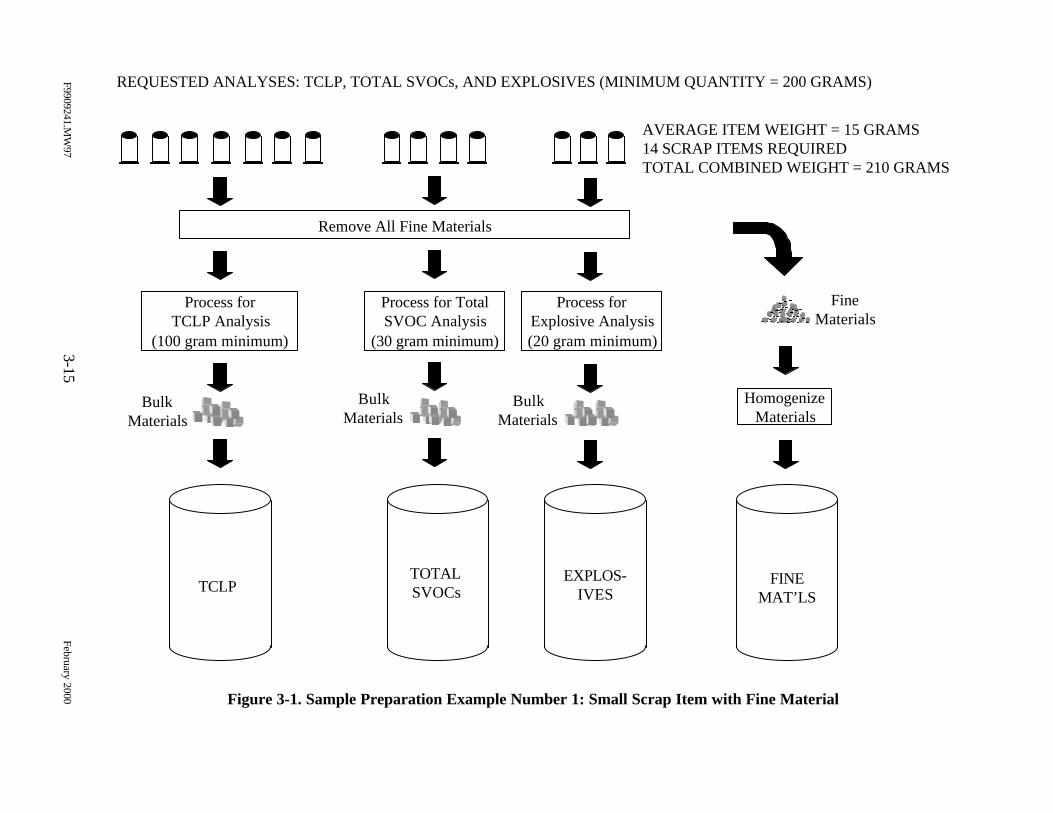
Figure 3-1. Sample Preparation Example Number 1: Small Scrap Item with Fine Material
F9909241.MW
973-15
February 2000
TCLPTOTALSVOCs
EXPLOS-IVES
FINEMAT’LS
REQUESTED ANALYSES: TCLP, TOTAL SVOCs, AND EXPLOSIVES (MINIMUM QUANTITY = 200 GRAMS)
AVERAGE ITEM WEIGHT = 15 GRAMS14 SCRAP ITEMS REQUIREDTOTAL COMBINED WEIGHT = 210 GRAMS
Process forTCLP Analysis
(100 gram minimum)
Process for TotalSVOC Analysis
(30 gram minimum)
Process forExplosive Analysis(20 gram minimum)
Remove All Fine Materials
BulkMaterials
BulkMaterials
BulkMaterials
FineMaterials
HomogenizeMaterials
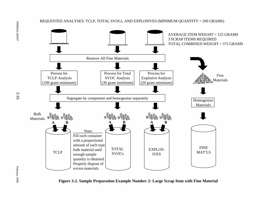
Figure 3-2. Sample Preparation Example Number 2: Large Scrap Item with Fine Material
F9909241.MW
973-16
February 2000
TCLPTOTALSVOCs
EXPLOS-IVES
FINEMAT’LS
REQUESTED ANALYSES: TCLP, TOTAL SVOCs, AND EXPLOSIVES (MINIMUM QUANTITY = 200 GRAMS)
AVERAGE ITEM WEIGHT = 125 GRAMS3 SCRAP ITEMS REQUIREDTOTAL COMBINED WEIGHT = 375 GRAMS
Process forTCLP Analysis
(100 gram minimum)
Process for TotalSVOC Analysis
(30 gram minimum)
Process forExplosive Analysis(20 gram minimum)
Remove All Fine Materials
HomogenizeMaterials
FineMaterials
Segregate by component and homogenize separately
BulkMaterials
A B A B A B
Note:Fill each containerwith a proportionalamount of each typebulk material untilenough samplequantity is obtained.Properly dispose ofexcess materials.
F9909241.MW97 3-17 February 2000
QC split samples will be collected at a rate of 1 split sample per 20 samples
prepared (5%). Samples targeted for QC will be prepared as stated in Section 3.3.2, but at least
400 grams of material will be processed. The QC split sample will be performed after the
material has been homogenized by filling an additional sample container for each analysis. All
sample containers will be filled simultaneously. Analysis of the split samples will be reviewed to
assess the representativeness of the samples submitted to the laboratory.
3.3.4 Sample Homogenization
Applying proper homogenization techniques will help ensure that conditions are
being accurately represented. Homogenization will be accomplished by mixing the entire
contents of the sample thoroughly with a plastic or Teflon spatula/spoon. Adequate mixing is
achieved by stirring the material in a circular manner and occasionally turning the material over.
The extent of the mixing required will depend on the nature of the sample and will be done to
achieve a consistent appearance prior to filling sample containers. In addition to the size
reduction required for TCLP analysis (less than 1 cm in narrowest dimension), particles greater
than 0.5 in. in their broadest dimension will be further reduced, if necessary, to provide materials
of consistent size. Once mixing is completed, the sample will be divided in half within the
mixing container and sample containers will be filled simultaneously by scooping sample
material alternatively from each half.
3.3.5 Sample and Shipping Containers
Table 3-2 lists the sample containers and minimum sample amounts required to
conduct the analyses for this effort.
Standard food/beverage coolers designated solely for sample shipment shall be
used for shipping the samples prepared for this effort. A copy of the COC record, shipping
waybill, and “inert certification” shall be included in each shipping container. The contents of the
shipping container should be specified as “environmental samples.”
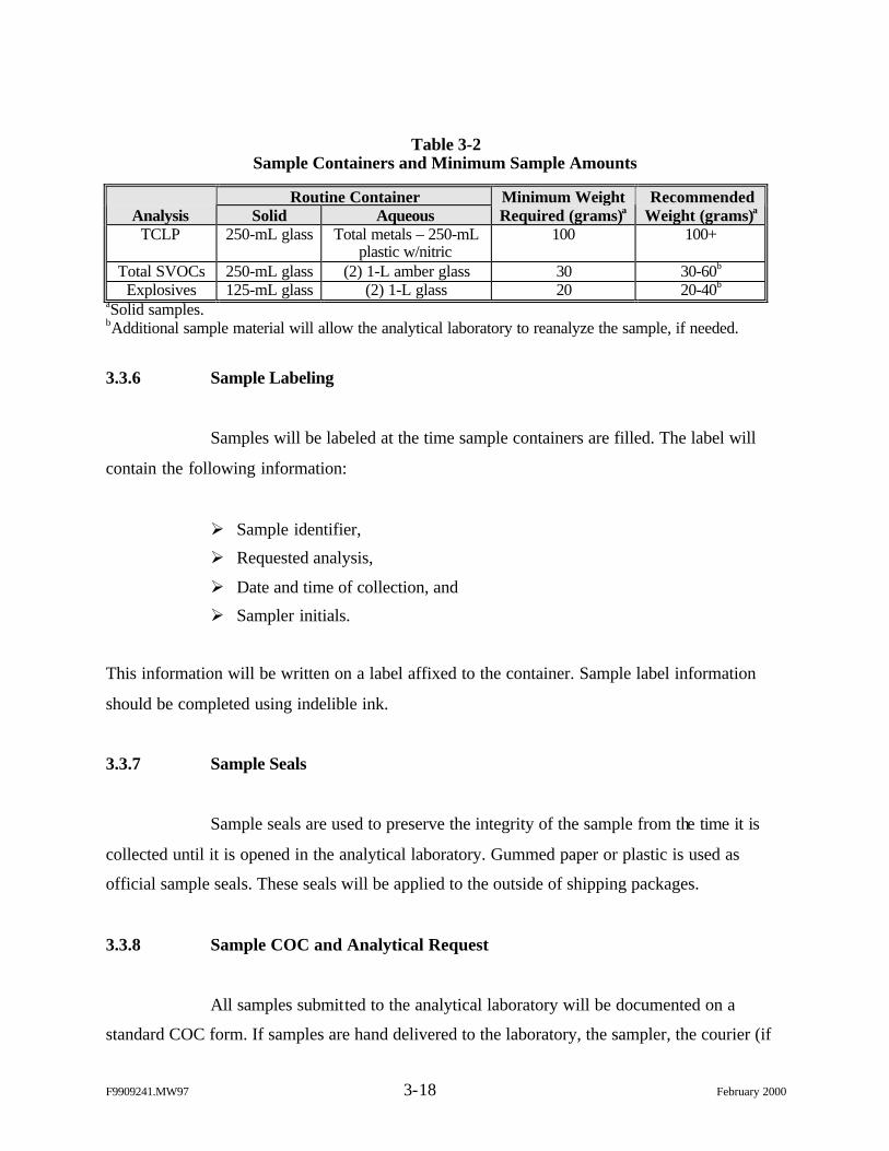
F9909241.MW97 3-18 February 2000
Table 3-2Sample Containers and Minimum Sample Amounts
Routine ContainerAnalysis Solid Aqueous
Minimum WeightRequired (grams)a
RecommendedWeight (grams)a
TCLP 250-mL glass Total metals – 250-mLplastic w/nitric
100 100+
Total SVOCs 250-mL glass (2) 1-L amber glass 30 30-60b
Explosives 125-mL glass (2) 1-L glass 20 20-40b
aSolid samples.bAdditional sample material will allow the analytical laboratory to reanalyze the sample, if needed.
3.3.6 Sample Labeling
Samples will be labeled at the time sample containers are filled. The label will
contain the following information:
Ø Sample identifier,
Ø Requested analysis,
Ø Date and time of collection, and
Ø Sampler initials.
This information will be written on a label affixed to the container. Sample label information
should be completed using indelible ink.
3.3.7 Sample Seals
Sample seals are used to preserve the integrity of the sample from the time it is
collected until it is opened in the analytical laboratory. Gummed paper or plastic is used as
official sample seals. These seals will be applied to the outside of shipping packages.
3.3.8 Sample COC and Analytical Request
All samples submitted to the analytical laboratory will be documented on a
standard COC form. If samples are hand delivered to the laboratory, the sampler, the courier (if
F9909241.MW97 3-19 February 2000
other than the sampler), and the receiver will sign the form. If samples are shipped via an
overnight express service, the number of the waybill will be substituted for the receiver
signature. The laboratory receiving clerk must still sign the COC to acknowledge receipt at the
laboratory.
The COC/analytical request will include the following minimum information:
Ø Place of collection (sample identification),
Ø Data and time of collection,
Ø Sample type (grab or composite),
Ø Sample description,
Ø Requested analyses,
Ø Number of containers,
Ø Signatures of personnel involved in the chain of possession,
Ø Inclusive dates of possession, and
Ø Instructions or reference to an attachment that provides additional instructionsto the analytical laboratory regarding non-routine activities.
3.3.9 Sample Preparation Documentation
Appendix D contains a Sample Preparation Record that will be used to record the
sample preparation information.
3.3.10 Equipment/Tools Decontamination
Equipment and tools that are reused during sample preparation will be
decontaminated as follows:
1. Wipe the equipment with a laboratory grade wipe that has been saturated witha 2% nitric acid solution.
2. Rinse thoroughly with distilled water.
3. Rinse with laboratory grade isopropanol.
F9909241.MW97 3-20 February 2000
4. Rinse thoroughly with laboratory grade organic-free water.
5. Dry the equipment with laboratory grade disposable wipes.
Unless the equipment is going to be used immediately, it should be stored in a clean place (on
plastic sheeting).
3.4 Sample Analysis
3.4.1 Analytical Methods/Procedures
The subcontract laboratory used for this study will be certified by the U.S. Army
Corps of Engineers Missouri River District for the applicable methods. The analytical procedures
for this project are specified as a sample matrix in Table 3-1. Chemical analyses will be
performed in accordance with the following guidelines:
Ø SW-846, Test Methods for Evaluating Solid Waste: Physical/ChemicalMethods, EPA Office of Solid Waste and Emergency Response, November1986 and
Ø EPA, Method for Chemical Analysis of Water and Wastes, EPA/600/4-79-020,March 1993.
As stated earlier, Modified Method 8330 will be used for the analysis of
nitroglycerin and PETN. The difference between the two methods (8330 and Modified 8330) is
the addition of a salting out procedure used for 8330. This procedure allows for lower (i.e., more
sensitive) detection limits of the analytes.
Analytical data report packages will be provided at an EPA “Level III” format or
U.S. Army Corps of Engineers standard data reporting format as discussed in Section 5.1.5.
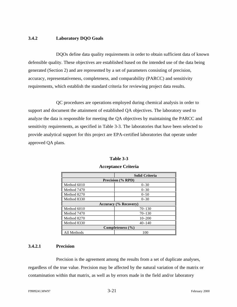
F9909241.MW97 3-21 February 2000
3.4.2 Laboratory DQO Goals
DQOs define data quality requirements in order to obtain sufficient data of known
defensible quality. These objectives are established based on the intended use of the data being
generated (Section 2) and are represented by a set of parameters consisting of precision,
accuracy, representativeness, completeness, and comparability (PARCC) and sensitivity
requirements, which establish the standard criteria for reviewing project data results.
QC procedures are operations employed during chemical analysis in order to
support and document the attainment of established QA objectives. The laboratory used to
analyze the data is responsible for meeting the QA objectives by maintaining the PARCC and
sensitivity requirements, as specified in Table 3-3. The laboratories that have been selected to
provide analytical support for this project are EPA-certified laboratories that operate under
approved QA plans.
Table 3-3
Acceptance Criteria
Solid CriteriaPrecision (% RPD)
Method 6010 0–30Method 7470 0–30Method 8270 0–50Method 8330 0–30
Accuracy (% Recovery)Method 6010 70–130Method 7470 70–130Method 8270 10–200Method 8330 40–140
Completeness (%)All Methods 100
3.4.2.1 Precision
Precision is the agreement among the results from a set of duplicate analyses,
regardless of the true value. Precision may be affected by the natural variation of the matrix or
contamination within that matrix, as well as by errors made in the field and/or laboratory
F9909241.MW97 3-22 February 2000
handling procedures. In order to assess this parameter, matrix spike/matrix spike duplicate
samples will be analyzed. Two representative aliquots of the same sample matrix will be
subjected to identical analytical procedures in order to assess the procedural precision of the
method through the calculation of relative percent difference (RPD). This value will be used to
ensure precision objectives have been met. Method-specific RPD limits will be provided in the
laboratory-specific reports of results. The number of matrix spike and matrix spike duplicate
samples will be determined in accordance with the specified methods.
3.4.2.2 Accuracy
Accuracy is defined as the closeness of agreement between the measured value
and the true value and is calculated as percent recovery. Sources of error include the sampling
process, field contamination, preservation, handling, sample matrix, sample preparation, and
analysis techniques. Analytical accuracy will be assessed by measuring the percent recovery of
known concentrations of target analytes spiked into a field sample (matrix spikes). Method-
specific percent recovery limits will be provided in the laboratory-specific reports of results.
3.4.2.3 Representativeness
Representativeness expresses the degree to which sample data accurately and
precisely represent the characteristics of a population of samples or an environmental condition.
Employing appropriate sampling strategies as described in Section 3.2 will ensure
representativeness. In the laboratory, representativeness may be enhanced by making certain that
all subsamples taken from a given sample are representative of the entire sample.
Representativeness will be assessed by the use of duplicate field and laboratory samples.
For the laboratory (matrix) duplicates, two representative aliquots of the same
sample matrix will be subjected to identical analytical procedures. The RPD between the two
sample results will be calculated.
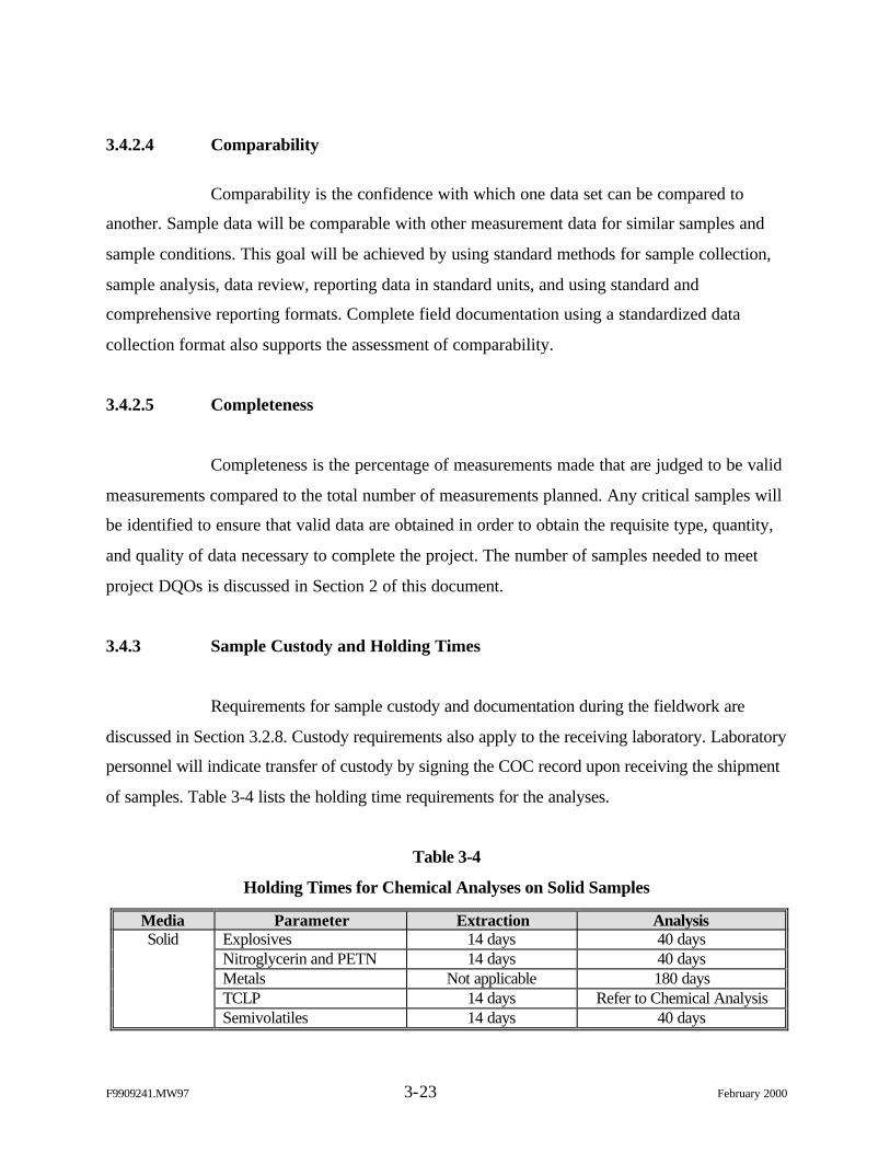
F9909241.MW97 3-23 February 2000
3.4.2.4 Comparability
Comparability is the confidence with which one data set can be compared to
another. Sample data will be comparable with other measurement data for similar samples and
sample conditions. This goal will be achieved by using standard methods for sample collection,
sample analysis, data review, reporting data in standard units, and using standard and
comprehensive reporting formats. Complete field documentation using a standardized data
collection format also supports the assessment of comparability.
3.4.2.5 Completeness
Completeness is the percentage of measurements made that are judged to be valid
measurements compared to the total number of measurements planned. Any critical samples will
be identified to ensure that valid data are obtained in order to obtain the requisite type, quantity,
and quality of data necessary to complete the project. The number of samples needed to meet
project DQOs is discussed in Section 2 of this document.
3.4.3 Sample Custody and Holding Times
Requirements for sample custody and documentation during the fieldwork are
discussed in Section 3.2.8. Custody requirements also apply to the receiving laboratory. Laboratory
personnel will indicate transfer of custody by signing the COC record upon receiving the shipment
of samples. Table 3-4 lists the holding time requirements for the analyses.
Table 3-4
Holding Times for Chemical Analyses on Solid Samples
Media Parameter Extraction AnalysisSolid Explosives 14 days 40 days
Nitroglycerin and PETN 14 days 40 daysMetals Not applicable 180 daysTCLP 14 days Refer to Chemical AnalysisSemivolatiles 14 days 40 days
F9909241.MW97 3-24 February 2000
3.4.4 Internal QC Checks
Internal QC checks are used to determine whether analytical operations are in
control, as well as determining the affect the sample matrix may have on data being generated.
These two aspects are described as batch QC and matrix-specific QC procedures, respectively. The
type and frequency of specific QC samples performed by the laboratory will be in accordance with
the specified analytical methods. Acceptance criteria and target ranges for the laboratory QC
samples are presented within the analytical methods and summarized in Table 3-3. Data that vary
from these target ranges will result in the implementation of appropriate corrective measures. Full
documentation of all actions taken will be recorded within a case narrative.
3.4.4.1 Batch QC
Typical batch QC for analyses to be performed for this project is described below.
Method Blanks. Method blanks are analyzed to assess the level of background
interference or contamination that exists in the analytical system and that might lead to the
reporting of elevated concentration levels or false positive data. At least one method blank will
be prepared and analyzed with every batch of samples processed. The concentration of all target
analytes in the blank will be below the method detection limit (MDL) or 5% of the measured
concentration in the sample. If the blank does not meet acceptance criteria, the source of
contamination will be investigated and appropriate corrective action will be taken and
documented. Corrective actions may include reanalysis of the blank and/or re-preparation and
reanalysis of the blank and all associated samples at the laboratory’s cost. Sample results will not
be corrected for blank contamination.
Laboratory Control Samples. Laboratory performance QC will be based on the
use of standard control matrices that are prepared independently from the standard solutions used
in establishing the calibration curve, to calculate precision and accuracy data. These QC data will
be compared on a per-batch basis, to the control limits of the methods, to verify compliance. This
data, along with method blank data, will be used to assess laboratory performance.
F9909241.MW97 3-25 February 2000
Other QC Samples. In order to maintain the quality of the data and laboratory
performance, the laboratory will implement the QC requirements and standards described in the
reference methods that is uses. These method-specific QC requirements include the following:
Ø Initial Calibration (metals and SVOCs);
Ø Initial Calibration Verification (metals);
Ø Initial Calibration Blank and Continuing Calibration Blank (metals);
Ø Continuing Calibration Verification (metals, explosives, and SVOCs);
Ø Interference Check Sample (metals);
Ø Tune (SVOCs);
Ø Linear Range Analysis (metals);
Ø Method Blank (metals, explosives, and SVOCs);
Ø Serial Dilution (metals);
Ø Laboratory Control Sample (metals, explosives, and SVOCs);
Ø Surrogate Spike (SVOCs); and
Ø Matrix spikes (metals, explosives, and SVOCs).
3.4.4.2 Matrix-Specific QC
Matrix-specific QC will be based on the use of an actual environmental sample
for precision and accuracy determinations and will rely on the analysis of matrix duplicates,
surrogate compounds, matrix spikes, and matrix spike duplicates. The required frequency of
these sample types is established within each specific analytical method. Results of these
samples will be used to assess the affect of sample matrix conditions on analytical data.

This page intentionally left blank.
F9909241.MW97 4-1 February 2000
4.0 WASTE STREAM-SPECIFIC SAMPLING PROTOCOLS
This section discusses the sampling protocol for each type of range scrap item.
Table 4-1 provides a summary of the sampling and analysis requirements for this
characterization effort. The following information is detailed for each waste stream identified in
Section 2 and listed in Table 4-1:
Ø Overview. An overview of the range scrap item identified as a waste streamwithin the inventory, including a general description and function of theassociated munitions item(s). Available schematics of typical munitions itemsare also provided.
Ø Characterization Rationale. A discussion of the evaluation factors specificto characterizing each waste stream, which includes scrap components andmaterials, composition of reactive materials associated with the munitionsitem, and maximum theoretical leaching limit evaluation (Section 2.7.2). Thepurpose of this discussion is to provide the rationale for the characterizationscheme and the data needed to determine which item within the waste streamrepresents the most conservative choice for sampling and analysis.
Typically, two types of tables will be used to summarize data pertinent to thecharacterization scheme. The first type of table will summarize thecomposition of the reactive materials (primer, propellant, smoke filler, etc.) orother materials (e.g., lead solder), which contain contaminants of concern,present in the munitions items associated with the waste stream. The secondtype of table will summarize the maximum theoretical leaching limitevaluation for each DoDAC within the waste stream and provide the basis forselecting the most conservative DoDAC for characterization.
Ø Sampling Protocol. The waste stream-specific sampling protocol detailingwhich item will be selected for characterization and the correspondinganalytical requirements.
Forty types of range scrap or waste streams are included in this characterization
effort. These 40 waste streams include 133 separate DoDACs out of a total of 262 DoDACs
identified in the munitions inventory for FORSCOM and TRADOC. The remaining DoDACs
either do not generate range scrap items at the firing point or produce firing range scrap that is
characterized through process knowledge. The munitions items associated with the 40 waste
streams in this characterization represent over 97% of the annual munitions expenditure for
TRADOC and FORSCOM. This is due to the extensive characterization of small
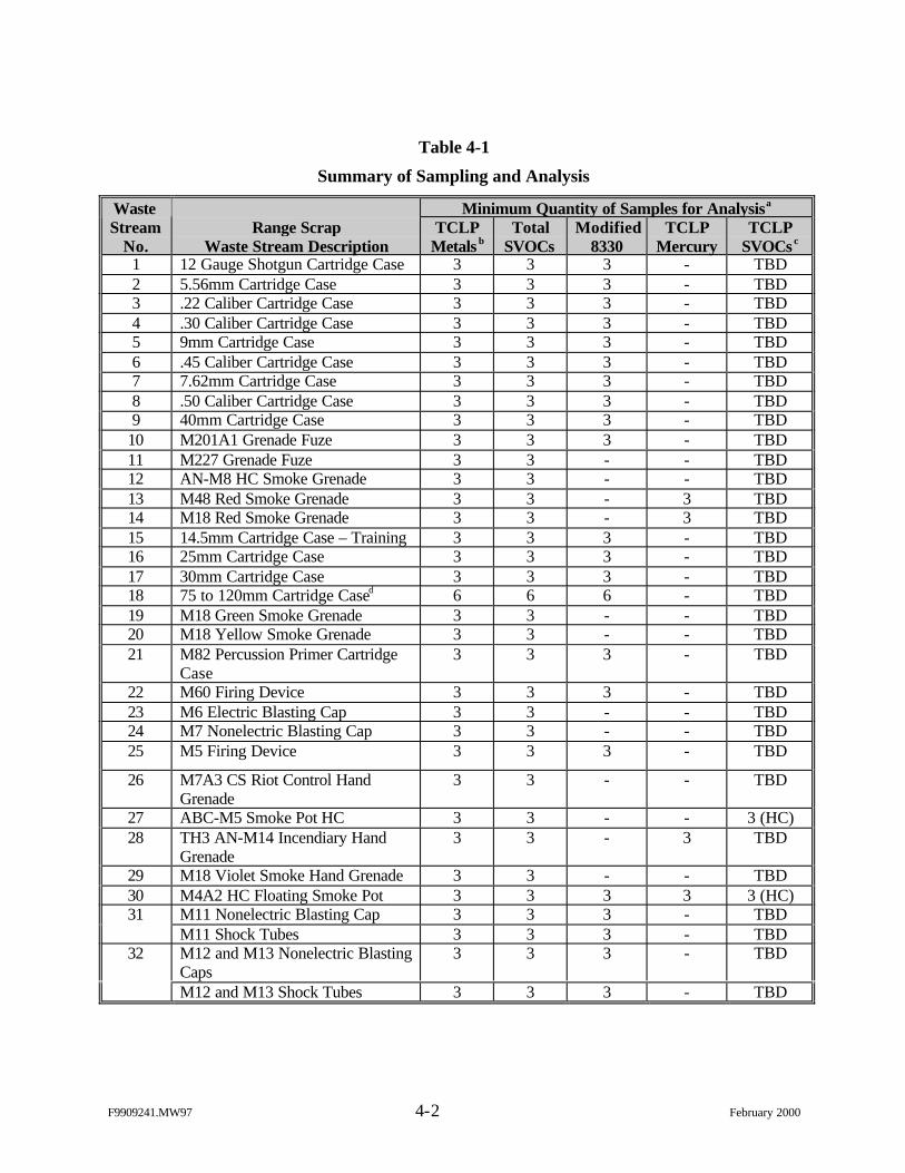
F9909241.MW97 4-2 February 2000
Table 4-1
Summary of Sampling and Analysis
Minimum Quantity of Samples for AnalysisaWasteStream
No.Range Scrap
Waste Stream DescriptionTCLP
Metals bTotal
SVOCsModified
8330TCLP
MercuryTCLP
SVOCs c
1 12 Gauge Shotgun Cartridge Case 3 3 3 - TBD2 5.56mm Cartridge Case 3 3 3 - TBD3 .22 Caliber Cartridge Case 3 3 3 - TBD4 .30 Caliber Cartridge Case 3 3 3 - TBD5 9mm Cartridge Case 3 3 3 - TBD6 .45 Caliber Cartridge Case 3 3 3 - TBD7 7.62mm Cartridge Case 3 3 3 - TBD8 .50 Caliber Cartridge Case 3 3 3 - TBD9 40mm Cartridge Case 3 3 3 - TBD
10 M201A1 Grenade Fuze 3 3 3 - TBD11 M227 Grenade Fuze 3 3 - - TBD12 AN-M8 HC Smoke Grenade 3 3 - - TBD13 M48 Red Smoke Grenade 3 3 - 3 TBD14 M18 Red Smoke Grenade 3 3 - 3 TBD15 14.5mm Cartridge Case – Training 3 3 3 - TBD16 25mm Cartridge Case 3 3 3 - TBD17 30mm Cartridge Case 3 3 3 - TBD18 75 to 120mm Cartridge Cased 6 6 6 - TBD19 M18 Green Smoke Grenade 3 3 - - TBD20 M18 Yellow Smoke Grenade 3 3 - - TBD21 M82 Percussion Primer Cartridge
Case3 3 3 - TBD
22 M60 Firing Device 3 3 3 - TBD23 M6 Electric Blasting Cap 3 3 - - TBD24 M7 Nonelectric Blasting Cap 3 3 - - TBD25 M5 Firing Device 3 3 3 - TBD
26 M7A3 CS Riot Control HandGrenade
3 3 - - TBD
27 ABC-M5 Smoke Pot HC 3 3 - - 3 (HC)28 TH3 AN-M14 Incendiary Hand
Grenade3 3 - 3 TBD
29 M18 Violet Smoke Hand Grenade 3 3 - - TBD30 M4A2 HC Floating Smoke Pot 3 3 3 3 3 (HC)31 M11 Nonelectric Blasting Cap 3 3 3 - TBD
M11 Shock Tubes 3 3 3 - TBD32 M12 and M13 Nonelectric Blasting
Caps3 3 3 - TBD
M12 and M13 Shock Tubes 3 3 3 - TBD
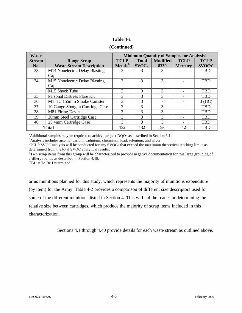
F9909241.MW97 4-3 February 2000
Table 4-1
(Continued)
Minimum Quantity of Samples for AnalysisaWasteStream
No.Range Scrap
Waste Stream DescriptionTCLP
Metals bTotal
SVOCsModified
8330TCLP
MercuryTCLP
SVOCs c
33 M14 Nonelectric Delay BlastingCap
3 3 3 - TBD
34 M15 Nonelectric Delay BlastingCap
3 3 3 - TBD
M15 Shock Tube 3 3 3 - TBD35 Personal Distress Flare Kit 3 3 3 - TBD36 M1 HC 155mm Smoke Canister 3 3 - - 3 (HC)37 10 Gauge Shotgun Cartridge Case 3 3 3 - TBD38 M81 Firing Device 3 3 3 - TBD39 20mm Steel Cartridge Case 3 3 3 - TBD40 25.4mm Cartridge Case 3 3 3 - TBD
Total 132 132 93 12 TBDaAdditional samples may be required to achieve project DQOs as described in Section 3.1.bAnalysis includes arsenic, barium, cadmium, chromium, lead, selenium, and silver.cTCLP SVOC analysis will be conducted for any SVOCs that exceed the maximum theoretical leaching limits asdetermined from the total SVOC analytical results.dTwo scrap items from this group will be characterized to provide negative documentation for this large grouping ofartillery rounds as described in Section 4.18.TBD = To Be Determined
arms munitions planned for this study, which represents the majority of munitions expenditure
(by item) for the Army. Table 4-2 provides a comparison of different size descriptors used for
some of the different munitions listed in Section 4. This will aid the reader in determining the
relative size between cartridges, which produce the majority of scrap items included in this
characterization.
Sections 4.1 through 4.40 provide details for each waste stream as outlined above.
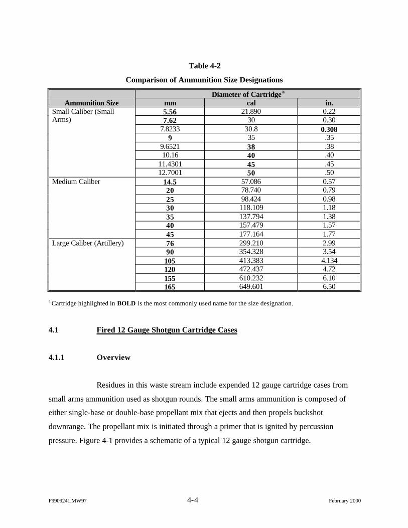
F9909241.MW97 4-4 February 2000
Table 4-2
Comparison of Ammunition Size Designations
Diameter of Cartridge a
Ammunition Size mm cal in.5.56 21.890 0.22Small Caliber (Small
Arms) 7.62 30 0.307.8233 30.8 0.308
9 35 .359.6521 38 .3810.16 40 .40
11.4301 45 .4512.7001 50 .50
Medium Caliber 14.5 57.086 0.5720 78.740 0.7925 98.424 0.9830 118.109 1.1835 137.794 1.3840 157.479 1.5745 177.164 1.77
Large Caliber (Artillery) 76 299.210 2.9990 354.328 3.54
105 413.383 4.134120 472.437 4.72155 610.232 6.10165 649.601 6.50
a Cartridge highlighted in BOLD is the most commonly used name for the size designation.
4.1 Fired 12 Gauge Shotgun Cartridge Cases
4.1.1 Overview
Residues in this waste stream include expended 12 gauge cartridge cases from
small arms ammunition used as shotgun rounds. The small arms ammunition is composed of
either single-base or double-base propellant mix that ejects and then propels buckshot
downrange. The propellant mix is initiated through a primer that is ignited by percussion
pressure. Figure 4-1 provides a schematic of a typical 12 gauge shotgun cartridge.
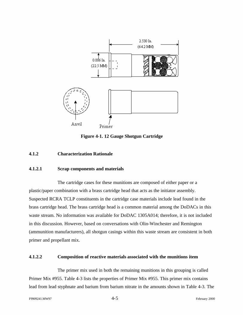
F9909241.MW97 4-5 February 2000
Figure 4-1. 12 Gauge Shotgun Cartridge
4.1.2 Characterization Rationale
4.1.2.1 Scrap components and materials
The cartridge cases for these munitions are composed of either paper or a
plastic/paper combination with a brass cartridge head that acts as the initiator assembly.
Suspected RCRA TCLP constituents in the cartridge case materials include lead found in the
brass cartridge head. The brass cartridge head is a common material among the DoDACs in this
waste stream. No information was available for DoDAC 1305A014; therefore, it is not included
in this discussion. However, based on conversations with Olin-Winchester and Remington
(ammunition manufacturers), all shotgun casings within this waste stream are consistent in both
primer and propellant mix.
4.1.2.2 Composition of reactive materials associated with the munitions item
The primer mix used in both the remaining munitions in this grouping is called
Primer Mix #955. Table 4-3 lists the properties of Primer Mix #955. This primer mix contains
lead from lead styphnate and barium from barium nitrate in the amounts shown in Table 4-3. The
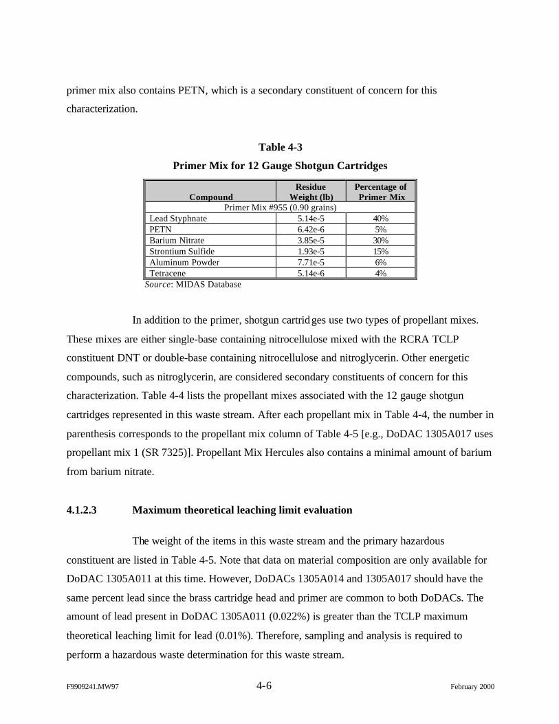
F9909241.MW97 4-6 February 2000
primer mix also contains PETN, which is a secondary constituent of concern for this
characterization.
Table 4-3
Primer Mix for 12 Gauge Shotgun Cartridges
CompoundResidue
Weight (lb)Percentage ofPrimer Mix
Primer Mix #955 (0.90 grains)Lead Styphnate 5.14e-5 40%PETN 6.42e-6 5%Barium Nitrate 3.85e-5 30%Strontium Sulfide 1.93e-5 15%Aluminum Powder 7.71e-5 6%Tetracene 5.14e-6 4%
Source: MIDAS Database
In addition to the primer, shotgun cartridges use two types of propellant mixes.
These mixes are either single-base containing nitrocellulose mixed with the RCRA TCLP
constituent DNT or double-base containing nitrocellulose and nitroglycerin. Other energetic
compounds, such as nitroglycerin, are considered secondary constituents of concern for this
characterization. Table 4-4 lists the propellant mixes associated with the 12 gauge shotgun
cartridges represented in this waste stream. After each propellant mix in Table 4-4, the number in
parenthesis corresponds to the propellant mix column of Table 4-5 [e.g., DoDAC 1305A017 uses
propellant mix 1 (SR 7325)]. Propellant Mix Hercules also contains a minimal amount of barium
from barium nitrate.
4.1.2.3 Maximum theoretical leaching limit evaluation
The weight of the items in this waste stream and the primary hazardous
constituent are listed in Table 4-5. Note that data on material composition are only available for
DoDAC 1305A011 at this time. However, DoDACs 1305A014 and 1305A017 should have the
same percent lead since the brass cartridge head and primer are common to both DoDACs. The
amount of lead present in DoDAC 1305A011 (0.022%) is greater than the TCLP maximum
theoretical leaching limit for lead (0.01%). Therefore, sampling and analysis is required to
perform a hazardous waste determination for this waste stream.
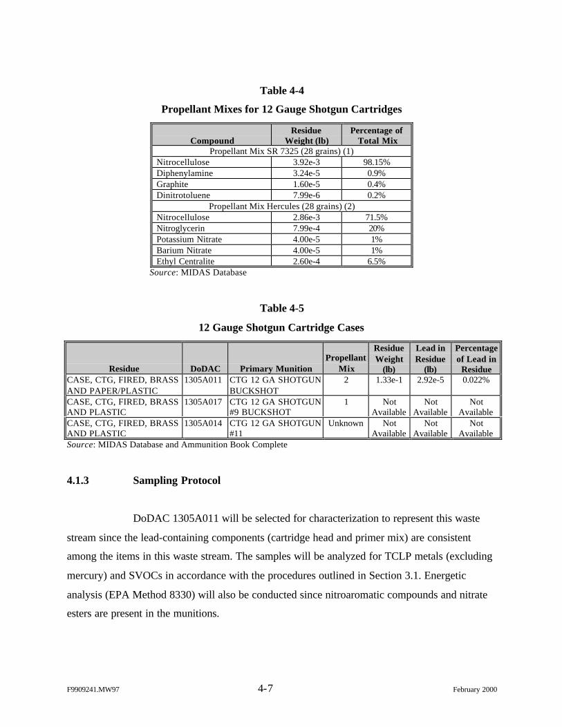
F9909241.MW97 4-7 February 2000
Table 4-4
Propellant Mixes for 12 Gauge Shotgun Cartridges
CompoundResidue
Weight (lb)Percentage of
Total MixPropellant Mix SR 7325 (28 grains) (1)
Nitrocellulose 3.92e-3 98.15%Diphenylamine 3.24e-5 0.9%Graphite 1.60e-5 0.4%Dinitrotoluene 7.99e-6 0.2%
Propellant Mix Hercules (28 grains) (2)Nitrocellulose 2.86e-3 71.5%Nitroglycerin 7.99e-4 20%Potassium Nitrate 4.00e-5 1%Barium Nitrate 4.00e-5 1%Ethyl Centralite 2.60e-4 6.5%
Source: MIDAS Database
Table 4-5
12 Gauge Shotgun Cartridge Cases
Residue DoDAC Primary MunitionPropellant
Mix
ResidueWeight
(lb)
Lead inResidue
(lb)
Percentageof Lead in
ResidueCASE, CTG, FIRED, BRASSAND PAPER/PLASTIC
1305A011 CTG 12 GA SHOTGUNBUCKSHOT
2 1.33e-1 2.92e-5 0.022%
CASE, CTG, FIRED, BRASSAND PLASTIC
1305A017 CTG 12 GA SHOTGUN#9 BUCKSHOT
1 NotAvailable
NotAvailable
NotAvailable
CASE, CTG, FIRED, BRASSAND PLASTIC
1305A014 CTG 12 GA SHOTGUN#11
Unknown NotAvailable
NotAvailable
NotAvailable
Source: MIDAS Database and Ammunition Book Complete
4.1.3 Sampling Protocol
DoDAC 1305A011 will be selected for characterization to represent this waste
stream since the lead-containing components (cartridge head and primer mix) are consistent
among the items in this waste stream. The samples will be analyzed for TCLP metals (excluding
mercury) and SVOCs in accordance with the procedures outlined in Section 3.1. Energetic
analysis (EPA Method 8330) will also be conducted since nitroaromatic compounds and nitrate
esters are present in the munitions.
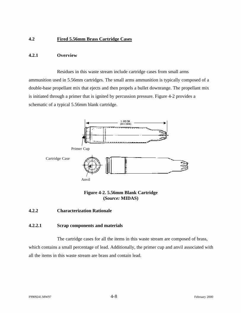
F9909241.MW97 4-8 February 2000
4.2 Fired 5.56mm Brass Cartridge Cases
4.2.1 Overview
Residues in this waste stream include cartridge cases from small arms
ammunition used in 5.56mm cartridges. The small arms ammunition is typically composed of a
double-base propellant mix that ejects and then propels a bullet downrange. The propellant mix
is initiated through a primer that is ignited by percussion pressure. Figure 4-2 provides a
schematic of a typical 5.56mm blank cartridge.
Figure 4-2. 5.56mm Blank Cartridge(Source: MIDAS)
4.2.2 Characterization Rationale
4.2.2.1 Scrap components and materials
The cartridge cases for all the items in this waste stream are composed of brass,
which contains a small percentage of lead. Additionally, the primer cup and anvil associated with
all the items in this waste stream are brass and contain lead.
Primer Cup
Cartridge Case
Anvil
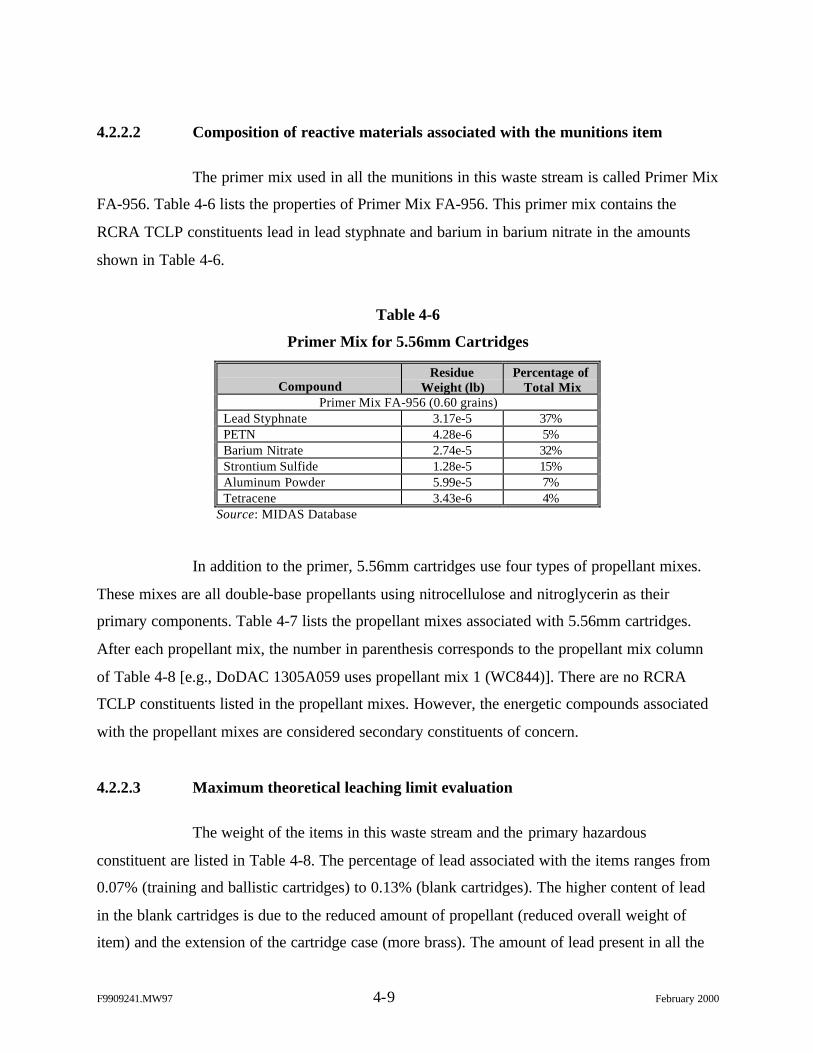
F9909241.MW97 4-9 February 2000
4.2.2.2 Composition of reactive materials associated with the munitions item
The primer mix used in all the munitions in this waste stream is called Primer Mix
FA-956. Table 4-6 lists the properties of Primer Mix FA-956. This primer mix contains the
RCRA TCLP constituents lead in lead styphnate and barium in barium nitrate in the amounts
shown in Table 4-6.
Table 4-6
Primer Mix for 5.56mm Cartridges
CompoundResidue
Weight (lb)Percentage of
Total MixPrimer Mix FA-956 (0.60 grains)
Lead Styphnate 3.17e-5 37%PETN 4.28e-6 5%Barium Nitrate 2.74e-5 32%Strontium Sulfide 1.28e-5 15%Aluminum Powder 5.99e-5 7%Tetracene 3.43e-6 4%
Source: MIDAS Database
In addition to the primer, 5.56mm cartridges use four types of propellant mixes.
These mixes are all double-base propellants using nitrocellulose and nitroglycerin as their
primary components. Table 4-7 lists the propellant mixes associated with 5.56mm cartridges.
After each propellant mix, the number in parenthesis corresponds to the propellant mix column
of Table 4-8 [e.g., DoDAC 1305A059 uses propellant mix 1 (WC844)]. There are no RCRA
TCLP constituents listed in the propellant mixes. However, the energetic compounds associated
with the propellant mixes are considered secondary constituents of concern.
4.2.2.3 Maximum theoretical leaching limit evaluation
The weight of the items in this waste stream and the primary hazardous
constituent are listed in Table 4-8. The percentage of lead associated with the items ranges from
0.07% (training and ballistic cartridges) to 0.13% (blank cartridges). The higher content of lead
in the blank cartridges is due to the reduced amount of propellant (reduced overall weight of
item) and the extension of the cartridge case (more brass). The amount of lead present in all the
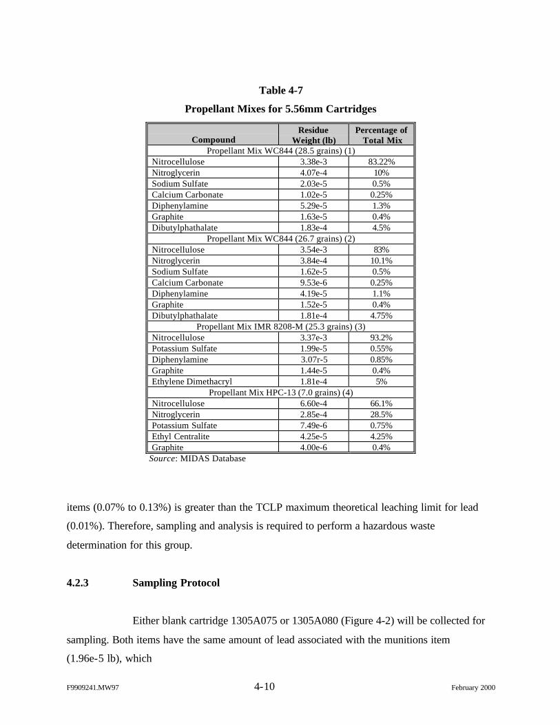
F9909241.MW97 4-10 February 2000
Table 4-7
Propellant Mixes for 5.56mm Cartridges
CompoundResidue
Weight (lb)Percentage of
Total MixPropellant Mix WC844 (28.5 grains) (1)
Nitrocellulose 3.38e-3 83.22%Nitroglycerin 4.07e-4 10%Sodium Sulfate 2.03e-5 0.5%Calcium Carbonate 1.02e-5 0.25%Diphenylamine 5.29e-5 1.3%Graphite 1.63e-5 0.4%Dibutylphathalate 1.83e-4 4.5%
Propellant Mix WC844 (26.7 grains) (2)Nitrocellulose 3.54e-3 83%Nitroglycerin 3.84e-4 10.1%Sodium Sulfate 1.62e-5 0.5%Calcium Carbonate 9.53e-6 0.25%Diphenylamine 4.19e-5 1.1%Graphite 1.52e-5 0.4%Dibutylphathalate 1.81e-4 4.75%
Propellant Mix IMR 8208-M (25.3 grains) (3)Nitrocellulose 3.37e-3 93.2%Potassium Sulfate 1.99e-5 0.55%Diphenylamine 3.07r-5 0.85%Graphite 1.44e-5 0.4%Ethylene Dimethacryl 1.81e-4 5%
Propellant Mix HPC-13 (7.0 grains) (4)Nitrocellulose 6.60e-4 66.1%Nitroglycerin 2.85e-4 28.5%Potassium Sulfate 7.49e-6 0.75%Ethyl Centralite 4.25e-5 4.25%Graphite 4.00e-6 0.4%
Source: MIDAS Database
items (0.07% to 0.13%) is greater than the TCLP maximum theoretical leaching limit for lead
(0.01%). Therefore, sampling and analysis is required to perform a hazardous waste
determination for this group.
4.2.3 Sampling Protocol
Either blank cartridge 1305A075 or 1305A080 (Figure 4-2) will be collected for
sampling. Both items have the same amount of lead associated with the munitions item
(1.96e-5 lb), which
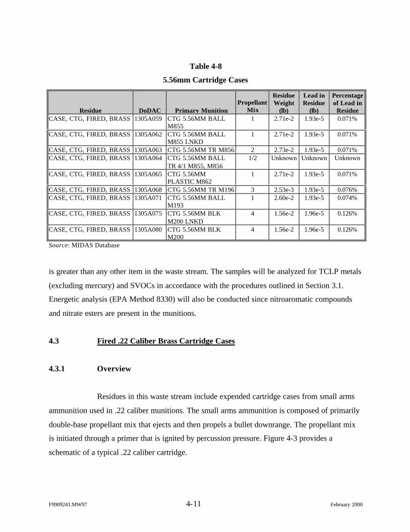
F9909241.MW97 4-11 February 2000
Table 4-8
5.56mm Cartridge Cases
Residue DoDAC Primary MunitionPropellant
Mix
ResidueWeight
(lb)
Lead inResidue
(lb)
Percentageof Lead in
ResidueCASE, CTG, FIRED, BRASS 1305A059 CTG 5.56MM BALL
M8551 2.71e-2 1.93e-5 0.071%
CASE, CTG, FIRED, BRASS 1305A062 CTG 5.56MM BALLM855 LNKD
1 2.71e-2 1.93e-5 0.071%
CASE, CTG, FIRED, BRASS 1305A063 CTG 5.56MM TR M856 2 2.73e-2 1.93e-5 0.071%CASE, CTG, FIRED, BRASS 1305A064 CTG 5.56MM BALL
TR 4/1 M855, M8561/2 Unknown Unknown Unknown
CASE, CTG, FIRED, BRASS 1305A065 CTG 5.56MMPLASTIC M862
1 2.71e-2 1.93e-5 0.071%
CASE, CTG, FIRED, BRASS 1305A068 CTG 5.56MM TR M196 3 2.53e-3 1.93e-5 0.076%CASE, CTG, FIRED, BRASS 1305A071 CTG 5.56MM BALL
M1931 2.60e-2 1.93e-5 0.074%
CASE, CTG, FIRED, BRASS 1305A075 CTG 5.56MM BLKM200 LNKD
4 1.56e-2 1.96e-5 0.126%
CASE, CTG, FIRED, BRASS 1305A080 CTG 5.56MM BLKM200
4 1.56e-2 1.96e-5 0.126%
Source: MIDAS Database
is greater than any other item in the waste stream. The samples will be analyzed for TCLP metals
(excluding mercury) and SVOCs in accordance with the procedures outlined in Section 3.1.
Energetic analysis (EPA Method 8330) will also be conducted since nitroaromatic compounds
and nitrate esters are present in the munitions.
4.3 Fired .22 Caliber Brass Cartridge Cases
4.3.1 Overview
Residues in this waste stream include expended cartridge cases from small arms
ammunition used in .22 caliber munitions. The small arms ammunition is composed of primarily
double-base propellant mix that ejects and then propels a bullet downrange. The propellant mix
is initiated through a primer that is ignited by percussion pressure. Figure 4-3 provides a
schematic of a typical .22 caliber cartridge.
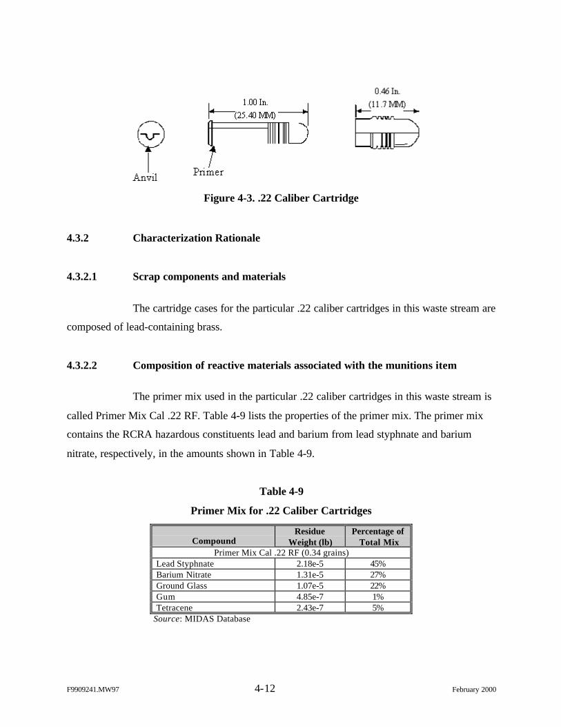
F9909241.MW97 4-12 February 2000
Figure 4-3. .22 Caliber Cartridge
4.3.2 Characterization Rationale
4.3.2.1 Scrap components and materials
The cartridge cases for the particular .22 caliber cartridges in this waste stream are
composed of lead-containing brass.
4.3.2.2 Composition of reactive materials associated with the munitions item
The primer mix used in the particular .22 caliber cartridges in this waste stream is
called Primer Mix Cal .22 RF. Table 4-9 lists the properties of the primer mix. The primer mix
contains the RCRA hazardous constituents lead and barium from lead styphnate and barium
nitrate, respectively, in the amounts shown in Table 4-9.
Table 4-9
Primer Mix for .22 Caliber Cartridges
CompoundResidue
Weight (lb)Percentage of
Total MixPrimer Mix Cal .22 RF (0.34 grains)
Lead Styphnate 2.18e-5 45%Barium Nitrate 1.31e-5 27%Ground Glass 1.07e-5 22%Gum 4.85e-7 1%Tetracene 2.43e-7 5%
Source: MIDAS Database
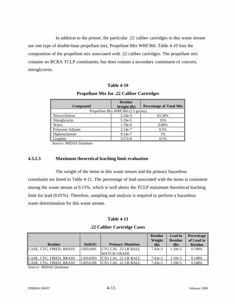
F9909241.MW97 4-13 February 2000
In addition to the primer, the particular .22 caliber cartridges in this waste stream
use one type of double-base propellant mix, Propellant Mix WRF360. Table 4-10 lists the
composition of the propellant mix associated with .22 caliber cartridges. The propellant mix
contains no RCRA TCLP constituents, but does contain a secondary constituent of concern,
nitroglycerin.
Table 4-10
Propellant Mix for .22 Caliber Cartridges
CompoundResidue
Weight (lb) Percentage of Total MixPropellant Mix WRF360 (2.5 grains)
Nitrocellulose 2.34e-4 83.34%Nitroglycerin 5.35e-5 15%Water 1.78e-6 0.06%Polyester Adipate 2.14e-7 0.5%Diphenylamine 9.14e-7 1%Graphite 3.57e-8 0.1%Source: MIDAS Database
4.3.2.3 Maximum theoretical leaching limit evaluation
The weight of the items in this waste stream and the primary hazardous
constituent are listed in Table 4-11. The percentage of lead associated with the items is consistent
among the waste stream at 0.15%, which is well above the TCLP maximum theoretical leaching
limit for lead (0.01%). Therefore, sampling and analysis is required to perform a hazardous
waste determination for this waste stream.
Table 4-11
.22 Caliber Cartridge Cases
Residue DoDAC Primary Munition
ResidueWeight
(lb)
Lead inResidue
(lb)
Percentageof Lead in
ResidueCASE, CTG, FIRED, BRASS 1305A091 CTG CAL .22 LR BALL
MATCH GRADE7.43e-3 1.10e-5 0.148%
CASE, CTG, FIRED, BRASS 1305A093 CTG CAL .22 LR BALL 7.43e-3 1.10e-5 0.148%CASE, CTG, FIRED, BRASS 1305A106 CTG CAL .22 LR BALL 7.43e-3 1.10e-5 0.148%Source: MIDAS Database
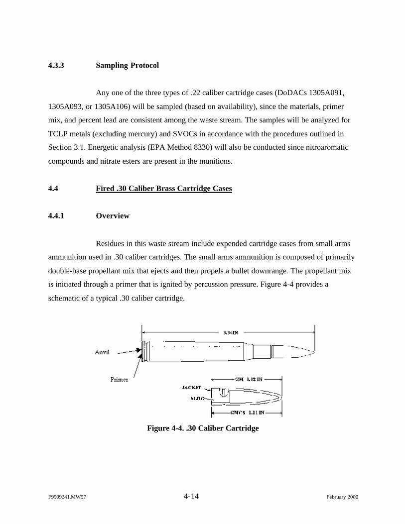
F9909241.MW97 4-14 February 2000
4.3.3 Sampling Protocol
Any one of the three types of .22 caliber cartridge cases (DoDACs 1305A091,
1305A093, or 1305A106) will be sampled (based on availability), since the materials, primer
mix, and percent lead are consistent among the waste stream. The samples will be analyzed for
TCLP metals (excluding mercury) and SVOCs in accordance with the procedures outlined in
Section 3.1. Energetic analysis (EPA Method 8330) will also be conducted since nitroaromatic
compounds and nitrate esters are present in the munitions.
4.4 Fired .30 Caliber Brass Cartridge Cases
4.4.1 Overview
Residues in this waste stream include expended cartridge cases from small arms
ammunition used in .30 caliber cartridges. The small arms ammunition is composed of primarily
double-base propellant mix that ejects and then propels a bullet downrange. The propellant mix
is initiated through a primer that is ignited by percussion pressure. Figure 4-4 provides a
schematic of a typical .30 caliber cartridge.
Figure 4-4. .30 Caliber Cartridge
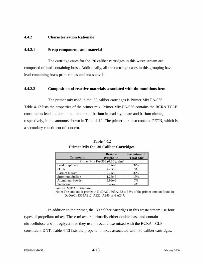
F9909241.MW97 4-15 February 2000
4.4.2 Characterization Rationale
4.4.2.1 Scrap components and materials
The cartridge cases for the .30 caliber cartridges in this waste stream are
composed of lead-containing brass. Additionally, all the cartridge cases in this grouping have
lead-containing brass primer cups and brass anvils.
4.4.2.2 Composition of reactive materials associated with the munitions item
The primer mix used in the .30 caliber cartridges is Primer Mix FA-956.
Table 4-12 lists the properties of the primer mix. Primer Mix FA-956 contains the RCRA TCLP
constituents lead and a minimal amount of barium in lead styphnate and barium nitrate,
respectively, in the amounts shown in Table 4-12. The primer mix also contains PETN, which is
a secondary constituent of concern.
Table 4-12Primer Mix for .30 Caliber Cartridges
CompoundResidue
Weight (lb)Percentage of
Total MixPrimer Mix FA-956 (0.60 grains)
Lead Styphnate 3.17e-5 37%PETN 4.28e-6 5%Barium Nitrate 2.74e-5 32%Strontium Sulfide 1.28e-5 15%Aluminum Powder 5.99e-6 7%Tetracene 3.43e-6 4%
Source: MIDAS DatabaseNote: The amount of primer in DoDAC 1305A182 is 58% of the primer amount found in
DoDACs 1305A212, A222, A246, and A247.
In addition to the primer, the .30 caliber cartridges in this waste stream use four
types of propellant mixes. These mixes are primarily either double-base and contain
nitrocellulose and nitroglycerin or they use nitrocellulose mixed with the RCRA TCLP
constituent DNT. Table 4-13 lists the propellant mixes associated with .30 caliber cartridges.
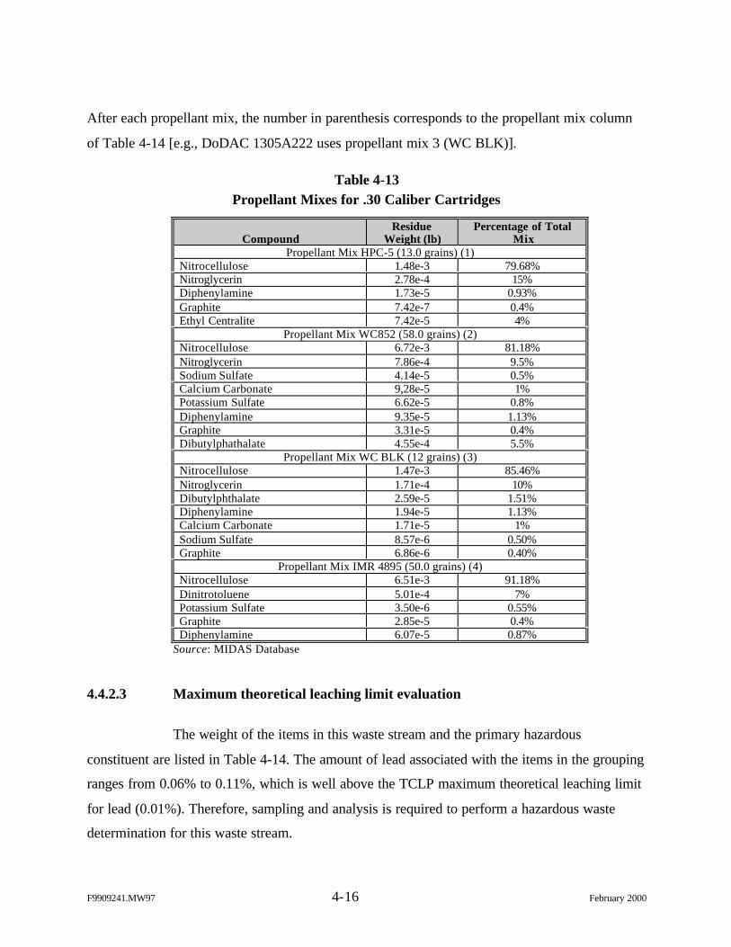
F9909241.MW97 4-16 February 2000
After each propellant mix, the number in parenthesis corresponds to the propellant mix column
of Table 4-14 [e.g., DoDAC 1305A222 uses propellant mix 3 (WC BLK)].
Table 4-13Propellant Mixes for .30 Caliber Cartridges
CompoundResidue
Weight (lb)Percentage of Total
MixPropellant Mix HPC-5 (13.0 grains) (1)
Nitrocellulose 1.48e-3 79.68%Nitroglycerin 2.78e-4 15%Diphenylamine 1.73e-5 0.93%Graphite 7.42e-7 0.4%Ethyl Centralite 7.42e-5 4%
Propellant Mix WC852 (58.0 grains) (2)Nitrocellulose 6.72e-3 81.18%Nitroglycerin 7.86e-4 9.5%Sodium Sulfate 4.14e-5 0.5%Calcium Carbonate 9,28e-5 1%Potassium Sulfate 6.62e-5 0.8%Diphenylamine 9.35e-5 1.13%Graphite 3.31e-5 0.4%Dibutylphathalate 4.55e-4 5.5%
Propellant Mix WC BLK (12 grains) (3)Nitrocellulose 1.47e-3 85.46%Nitroglycerin 1.71e-4 10%Dibutylphthalate 2.59e-5 1.51%Diphenylamine 1.94e-5 1.13%Calcium Carbonate 1.71e-5 1%Sodium Sulfate 8.57e-6 0.50%Graphite 6.86e-6 0.40%
Propellant Mix IMR 4895 (50.0 grains) (4)Nitrocellulose 6.51e-3 91.18%Dinitrotoluene 5.01e-4 7%Potassium Sulfate 3.50e-6 0.55%Graphite 2.85e-5 0.4%Diphenylamine 6.07e-5 0.87%
Source: MIDAS Database
4.4.2.3 Maximum theoretical leaching limit evaluation
The weight of the items in this waste stream and the primary hazardous
constituent are listed in Table 4-14. The amount of lead associated with the items in the grouping
ranges from 0.06% to 0.11%, which is well above the TCLP maximum theoretical leaching limit
for lead (0.01%). Therefore, sampling and analysis is required to perform a hazardous waste
determination for this waste stream.
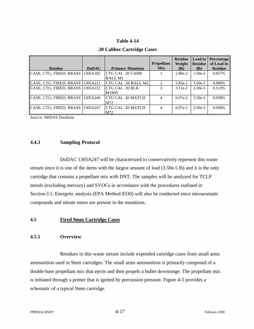
F9909241.MW97 4-17 February 2000
Table 4-14
.30 Caliber Cartridge Cases
Residue DoDAC Primary MunitionPropellant
Mix
ResidueWeight
(lb)
Lead inResidue
(lb)
Percentageof Lead in
ResidueCASE, CTG, FIRED, BRASS 1305A182 CTG CAL .30 CARB
BALL M11 2.80e-2 1.59e-5 0.057%
CASE, CTG, FIRED, BRASS 1305A212 CTG CAL .30 BALL M2 2 5.83e-2 3.50e-5 0.060%CASE, CTG, FIRED, BRASS 1305A222 CTG CAL .30 BLK
M19093 3.11e-2 3.50e-5 0.113%
CASE, CTG, FIRED, BRASS 1305A246 CTG CAL .30 MATCHM72
4 6.07e-2 3.50e-5 0.058%
CASE, CTG, FIRED, BRASS 1305A247 CTG CAL .30 MATCHM72
4 6.07e-2 3.50e-5 0.058%
Source: MIDAS Database
4.4.3 Sampling Protocol
DoDAC 1305A247 will be characterized to conservatively represent this waste
stream since it is one of the items with the largest amount of lead (3.50e-5 lb) and it is the only
cartridge that contains a propellant mix with DNT. The samples will be analyzed for TCLP
metals (excluding mercury) and SVOCs in accordance with the procedures outlined in
Section 3.1. Energetic analysis (EPA Method 8330) will also be conducted since nitroaromatic
compounds and nitrate esters are present in the munitions.
4.5 Fired 9mm Cartridge Cases
4.5.1 Overview
Residues in this waste stream include expended cartridge cases from small arms
ammunition used in 9mm cartridges. The small arms ammunition is primarily composed of a
double-base propellant mix that ejects and then propels a bullet downrange. The propellant mix
is initiated through a primer that is ignited by percussion pressure. Figure 4-5 provides a
schematic of a typical 9mm cartridge.
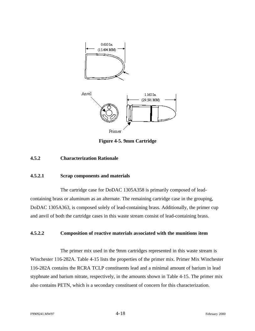
F9909241.MW97 4-18 February 2000
Figure 4-5. 9mm Cartridge
4.5.2 Characterization Rationale
4.5.2.1 Scrap components and materials
The cartridge case for DoDAC 1305A358 is primarily composed of lead-
containing brass or aluminum as an alternate. The remaining cartridge case in the grouping,
DoDAC 1305A363, is composed solely of lead-containing brass. Additionally, the primer cup
and anvil of both the cartridge cases in this waste stream consist of lead-containing brass.
4.5.2.2 Composition of reactive materials associated with the munitions item
The primer mix used in the 9mm cartridges represented in this waste stream is
Winchester 116-282A. Table 4-15 lists the properties of the primer mix. Primer Mix Winchester
116-282A contains the RCRA TCLP constituents lead and a minimal amount of barium in lead
styphnate and barium nitrate, respectively, in the amounts shown in Table 4-15. The primer mix
also contains PETN, which is a secondary constituent of concern for this characterization.
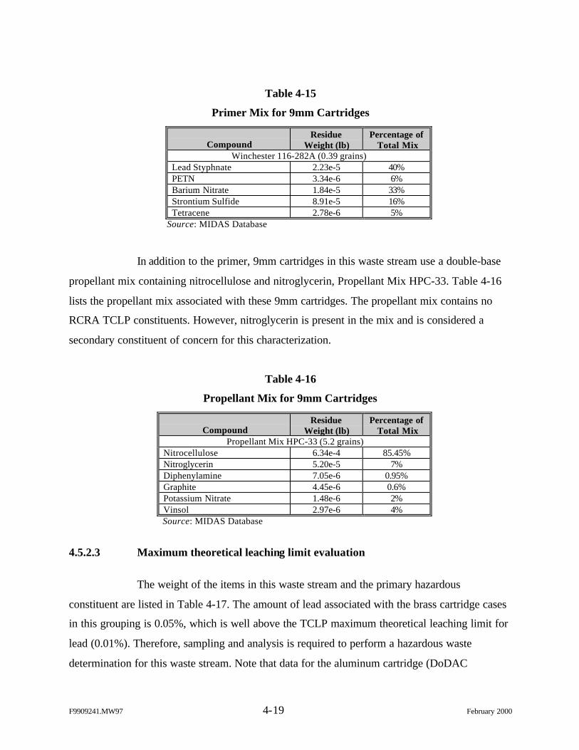
F9909241.MW97 4-19 February 2000
Table 4-15
Primer Mix for 9mm Cartridges
CompoundResidue
Weight (lb)Percentage of
Total MixWinchester 116-282A (0.39 grains)
Lead Styphnate 2.23e-5 40%PETN 3.34e-6 6%Barium Nitrate 1.84e-5 33%Strontium Sulfide 8.91e-5 16%Tetracene 2.78e-6 5%
Source: MIDAS Database
In addition to the primer, 9mm cartridges in this waste stream use a double-base
propellant mix containing nitrocellulose and nitroglycerin, Propellant Mix HPC-33. Table 4-16
lists the propellant mix associated with these 9mm cartridges. The propellant mix contains no
RCRA TCLP constituents. However, nitroglycerin is present in the mix and is considered a
secondary constituent of concern for this characterization.
Table 4-16
Propellant Mix for 9mm Cartridges
CompoundResidue
Weight (lb)Percentage of
Total MixPropellant Mix HPC-33 (5.2 grains)
Nitrocellulose 6.34e-4 85.45%Nitroglycerin 5.20e-5 7%Diphenylamine 7.05e-6 0.95%Graphite 4.45e-6 0.6%Potassium Nitrate 1.48e-6 2%Vinsol 2.97e-6 4%Source: MIDAS Database
4.5.2.3 Maximum theoretical leaching limit evaluation
The weight of the items in this waste stream and the primary hazardous
constituent are listed in Table 4-17. The amount of lead associated with the brass cartridge cases
in this grouping is 0.05%, which is well above the TCLP maximum theoretical leaching limit for
lead (0.01%). Therefore, sampling and analysis is required to perform a hazardous waste
determination for this waste stream. Note that data for the aluminum cartridge (DoDAC
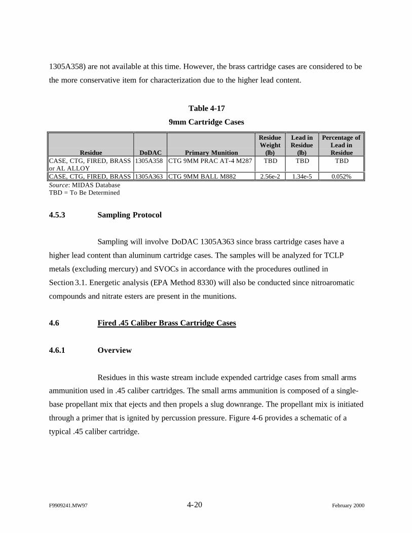
F9909241.MW97 4-20 February 2000
1305A358) are not available at this time. However, the brass cartridge cases are considered to be
the more conservative item for characterization due to the higher lead content.
Table 4-17
9mm Cartridge Cases
Residue DoDAC Primary Munition
ResidueWeight
(lb)
Lead inResidue
(lb)
Percentage ofLead inResidue
CASE, CTG, FIRED, BRASSor AL ALLOY
1305A358 CTG 9MM PRAC AT-4 M287 TBD TBD TBD
CASE, CTG, FIRED, BRASS 1305A363 CTG 9MM BALL M882 2.56e-2 1.34e-5 0.052%Source: MIDAS DatabaseTBD = To Be Determined
4.5.3 Sampling Protocol
Sampling will involve DoDAC 1305A363 since brass cartridge cases have a
higher lead content than aluminum cartridge cases. The samples will be analyzed for TCLP
metals (excluding mercury) and SVOCs in accordance with the procedures outlined in
Section 3.1. Energetic analysis (EPA Method 8330) will also be conducted since nitroaromatic
compounds and nitrate esters are present in the munitions.
4.6 Fired .45 Caliber Brass Cartridge Cases
4.6.1 Overview
Residues in this waste stream include expended cartridge cases from small arms
ammunition used in .45 caliber cartridges. The small arms ammunition is composed of a single-
base propellant mix that ejects and then propels a slug downrange. The propellant mix is initiated
through a primer that is ignited by percussion pressure. Figure 4-6 provides a schematic of a
typical .45 caliber cartridge.
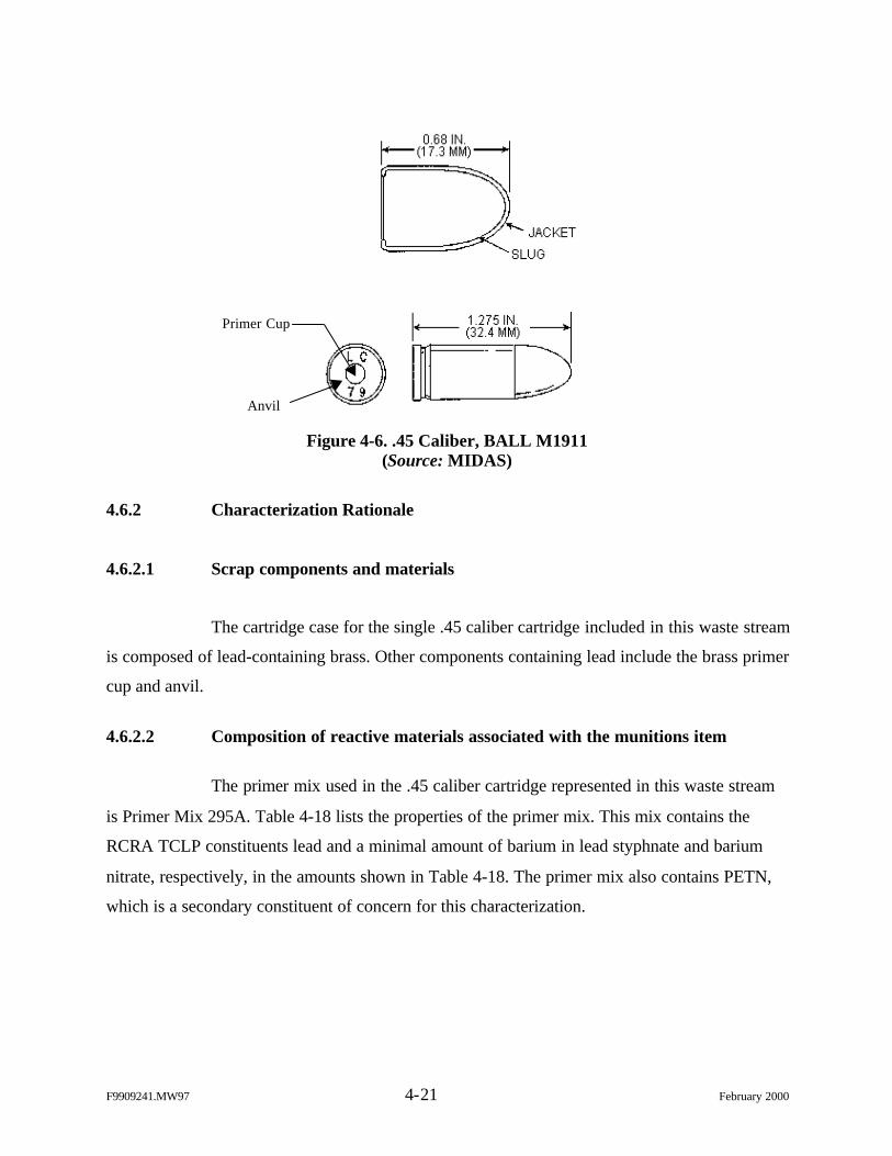
F9909241.MW97 4-21 February 2000
Figure 4-6. .45 Caliber, BALL M1911(Source: MIDAS)
4.6.2 Characterization Rationale
4.6.2.1 Scrap components and materials
The cartridge case for the single .45 caliber cartridge included in this waste stream
is composed of lead-containing brass. Other components containing lead include the brass primer
cup and anvil.
4.6.2.2 Composition of reactive materials associated with the munitions item
The primer mix used in the .45 caliber cartridge represented in this waste stream
is Primer Mix 295A. Table 4-18 lists the properties of the primer mix. This mix contains the
RCRA TCLP constituents lead and a minimal amount of barium in lead styphnate and barium
nitrate, respectively, in the amounts shown in Table 4-18. The primer mix also contains PETN,
which is a secondary constituent of concern for this characterization.
Primer Cup
Anvil
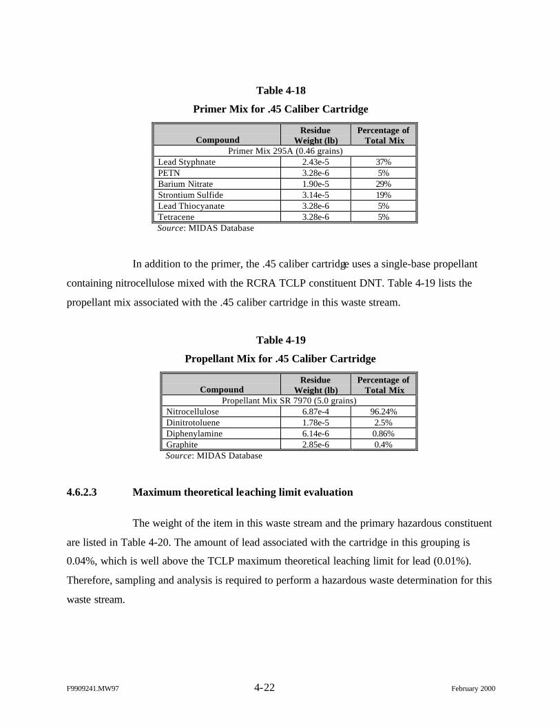
F9909241.MW97 4-22 February 2000
Table 4-18
Primer Mix for .45 Caliber Cartridge
CompoundResidue
Weight (lb)Percentage of
Total MixPrimer Mix 295A (0.46 grains)
Lead Styphnate 2.43e-5 37%PETN 3.28e-6 5%Barium Nitrate 1.90e-5 29%Strontium Sulfide 3.14e-5 19%Lead Thiocyanate 3.28e-6 5%Tetracene 3.28e-6 5%Source: MIDAS Database
In addition to the primer, the .45 caliber cartridge uses a single-base propellant
containing nitrocellulose mixed with the RCRA TCLP constituent DNT. Table 4-19 lists the
propellant mix associated with the .45 caliber cartridge in this waste stream.
Table 4-19
Propellant Mix for .45 Caliber Cartridge
CompoundResidue
Weight (lb)Percentage of
Total MixPropellant Mix SR 7970 (5.0 grains)
Nitrocellulose 6.87e-4 96.24%Dinitrotoluene 1.78e-5 2.5%Diphenylamine 6.14e-6 0.86%Graphite 2.85e-6 0.4%Source: MIDAS Database
4.6.2.3 Maximum theoretical leaching limit evaluation
The weight of the item in this waste stream and the primary hazardous constituent
are listed in Table 4-20. The amount of lead associated with the cartridge in this grouping is
0.04%, which is well above the TCLP maximum theoretical leaching limit for lead (0.01%).
Therefore, sampling and analysis is required to perform a hazardous waste determination for this
waste stream.
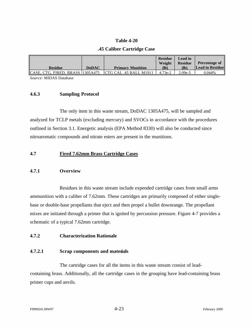
F9909241.MW97 4-23 February 2000
Table 4-20
.45 Caliber Cartridge Case
Residue DoDAC Primary Munition
ResidueWeight
(lb)
Lead inResidue
(lb)Percentage of
Lead in ResidueCASE, CTG, FIRED, BRASS 1305A475 CTG CAL .45 BALL M1911 4.73e-2 2.09e-5 0.044%Source: MIDAS Database
4.6.3 Sampling Protocol
The only item in this waste stream, DoDAC 1305A475, will be sampled and
analyzed for TCLP metals (excluding mercury) and SVOCs in accordance with the procedures
outlined in Section 3.1. Energetic analysis (EPA Method 8330) will also be conducted since
nitroaromatic compounds and nitrate esters are present in the munitions.
4.7 Fired 7.62mm Brass Cartridge Cases
4.7.1 Overview
Residues in this waste stream include expended cartridge cases from small arms
ammunition with a caliber of 7.62mm. These cartridges are primarily composed of either single-
base or double-base propellants that eject and then propel a bullet downrange. The propellant
mixes are initiated through a primer that is ignited by percussion pressure. Figure 4-7 provides a
schematic of a typical 7.62mm cartridge.
4.7.2 Characterization Rationale
4.7.2.1 Scrap components and materials
The cartridge cases for all the items in this waste stream consist of lead-
containing brass. Additionally, all the cartridge cases in the grouping have lead-containing brass
primer cups and anvils.
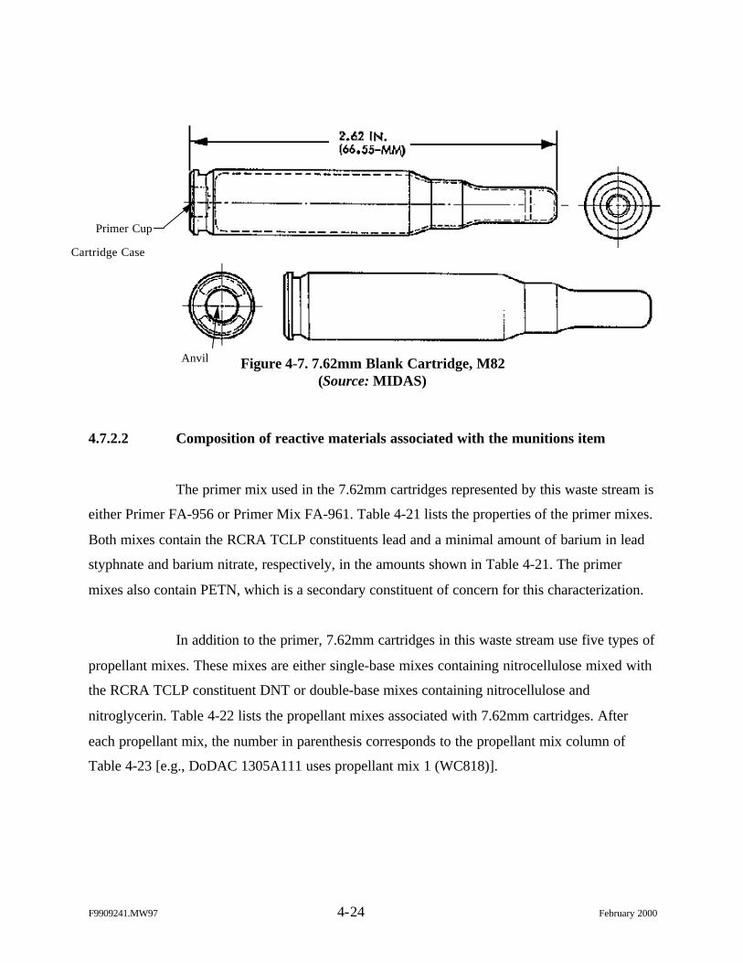
F9909241.MW97 4-24 February 2000
Figure 4-7. 7.62mm Blank Cartridge, M82(Source: MIDAS)
4.7.2.2 Composition of reactive materials associated with the munitions item
The primer mix used in the 7.62mm cartridges represented by this waste stream is
either Primer FA-956 or Primer Mix FA-961. Table 4-21 lists the properties of the primer mixes.
Both mixes contain the RCRA TCLP constituents lead and a minimal amount of barium in lead
styphnate and barium nitrate, respectively, in the amounts shown in Table 4-21. The primer
mixes also contain PETN, which is a secondary constituent of concern for this characterization.
In addition to the primer, 7.62mm cartridges in this waste stream use five types of
propellant mixes. These mixes are either single-base mixes containing nitrocellulose mixed with
the RCRA TCLP constituent DNT or double-base mixes containing nitrocellulose and
nitroglycerin. Table 4-22 lists the propellant mixes associated with 7.62mm cartridges. After
each propellant mix, the number in parenthesis corresponds to the propellant mix column of
Table 4-23 [e.g., DoDAC 1305A111 uses propellant mix 1 (WC818)].
Cartridge Case
Primer Cup
Anvil
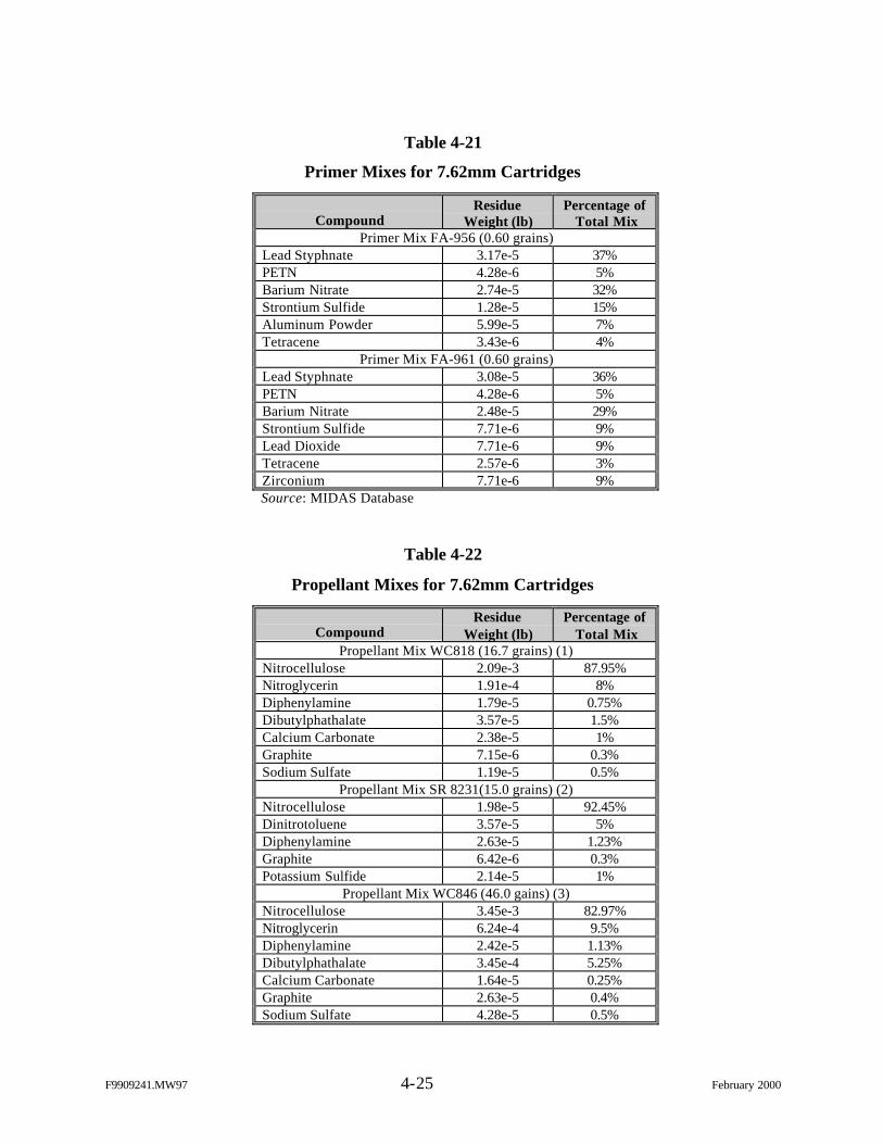
F9909241.MW97 4-25 February 2000
Table 4-21
Primer Mixes for 7.62mm Cartridges
CompoundResidue
Weight (lb)Percentage of
Total MixPrimer Mix FA-956 (0.60 grains)
Lead Styphnate 3.17e-5 37%PETN 4.28e-6 5%Barium Nitrate 2.74e-5 32%Strontium Sulfide 1.28e-5 15%Aluminum Powder 5.99e-5 7%Tetracene 3.43e-6 4%
Primer Mix FA-961 (0.60 grains)Lead Styphnate 3.08e-5 36%PETN 4.28e-6 5%Barium Nitrate 2.48e-5 29%Strontium Sulfide 7.71e-6 9%Lead Dioxide 7.71e-6 9%Tetracene 2.57e-6 3%Zirconium 7.71e-6 9%Source: MIDAS Database
Table 4-22
Propellant Mixes for 7.62mm Cartridges
CompoundResidue
Weight (lb)Percentage of
Total MixPropellant Mix WC818 (16.7 grains) (1)
Nitrocellulose 2.09e-3 87.95%Nitroglycerin 1.91e-4 8%Diphenylamine 1.79e-5 0.75%Dibutylphathalate 3.57e-5 1.5%Calcium Carbonate 2.38e-5 1%Graphite 7.15e-6 0.3%Sodium Sulfate 1.19e-5 0.5%
Propellant Mix SR 8231(15.0 grains) (2)Nitrocellulose 1.98e-5 92.45%Dinitrotoluene 3.57e-5 5%Diphenylamine 2.63e-5 1.23%Graphite 6.42e-6 0.3%Potassium Sulfide 2.14e-5 1%
Propellant Mix WC846 (46.0 gains) (3)Nitrocellulose 3.45e-3 82.97%Nitroglycerin 6.24e-4 9.5%Diphenylamine 2.42e-5 1.13%Dibutylphathalate 3.45e-4 5.25%Calcium Carbonate 1.64e-5 0.25%Graphite 2.63e-5 0.4%Sodium Sulfate 4.28e-5 0.5%
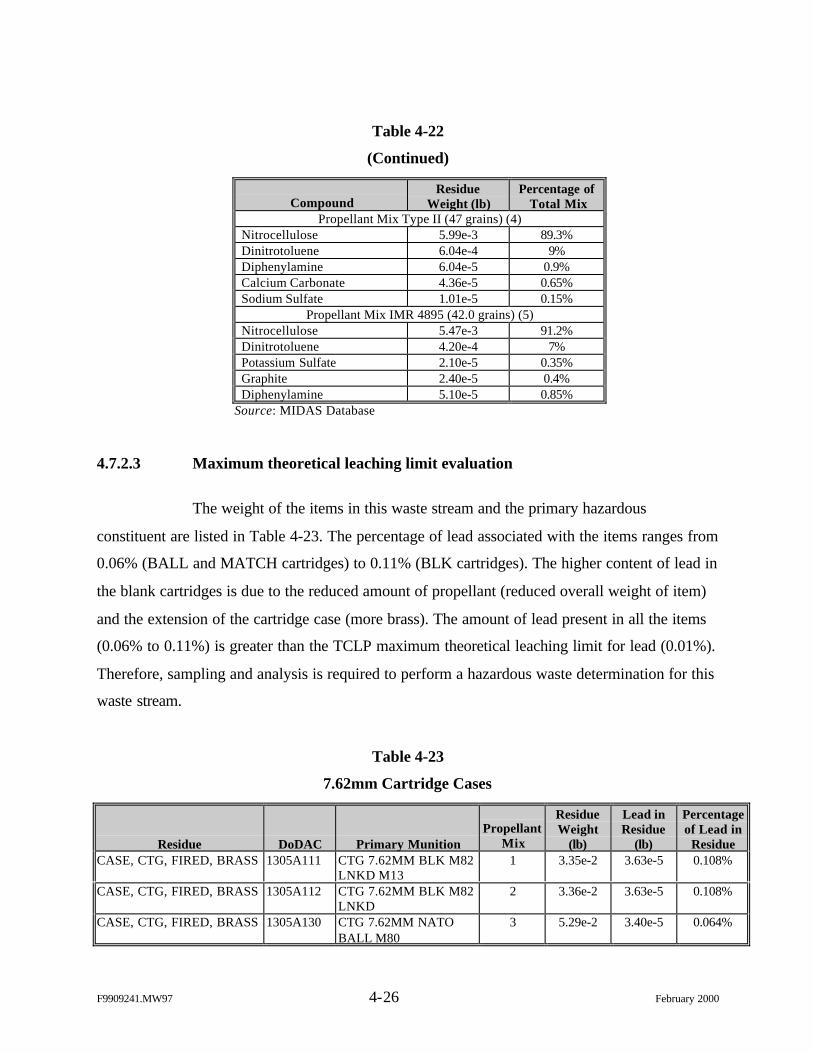
F9909241.MW97 4-26 February 2000
Table 4-22
(Continued)
CompoundResidue
Weight (lb)Percentage of
Total MixPropellant Mix Type II (47 grains) (4)
Nitrocellulose 5.99e-3 89.3%Dinitrotoluene 6.04e-4 9%Diphenylamine 6.04e-5 0.9%Calcium Carbonate 4.36e-5 0.65%Sodium Sulfate 1.01e-5 0.15%
Propellant Mix IMR 4895 (42.0 grains) (5)Nitrocellulose 5.47e-3 91.2%Dinitrotoluene 4.20e-4 7%Potassium Sulfate 2.10e-5 0.35%Graphite 2.40e-5 0.4%Diphenylamine 5.10e-5 0.85%
Source: MIDAS Database
4.7.2.3 Maximum theoretical leaching limit evaluation
The weight of the items in this waste stream and the primary hazardous
constituent are listed in Table 4-23. The percentage of lead associated with the items ranges from
0.06% (BALL and MATCH cartridges) to 0.11% (BLK cartridges). The higher content of lead in
the blank cartridges is due to the reduced amount of propellant (reduced overall weight of item)
and the extension of the cartridge case (more brass). The amount of lead present in all the items
(0.06% to 0.11%) is greater than the TCLP maximum theoretical leaching limit for lead (0.01%).
Therefore, sampling and analysis is required to perform a hazardous waste determination for this
waste stream.
Table 4-23
7.62mm Cartridge Cases
Residue DoDAC Primary MunitionPropellant
Mix
ResidueWeight
(lb)
Lead inResidue
(lb)
Percentageof Lead in
ResidueCASE, CTG, FIRED, BRASS 1305A111 CTG 7.62MM BLK M82
LNKD M131 3.35e-2 3.63e-5 0.108%
CASE, CTG, FIRED, BRASS 1305A112 CTG 7.62MM BLK M82LNKD
2 3.36e-2 3.63e-5 0.108%
CASE, CTG, FIRED, BRASS 1305A130 CTG 7.62MM NATOBALL M80
3 5.29e-2 3.40e-5 0.064%
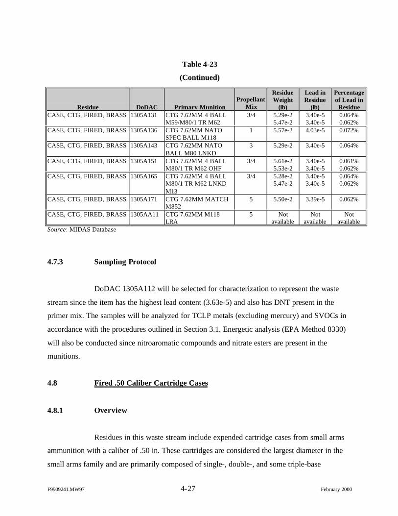
F9909241.MW97 4-27 February 2000
Table 4-23
(Continued)
Residue DoDAC Primary MunitionPropellant
Mix
ResidueWeight
(lb)
Lead inResidue
(lb)
Percentageof Lead in
ResidueCASE, CTG, FIRED, BRASS 1305A131 CTG 7.62MM 4 BALL
M59/M80/1 TR M623/4 5.29e-2
5.47e-23.40e-53.40e-5
0.064%0.062%
CASE, CTG, FIRED, BRASS 1305A136 CTG 7.62MM NATOSPEC BALL M118
1 5.57e-2 4.03e-5 0.072%
CASE, CTG, FIRED, BRASS 1305A143 CTG 7.62MM NATOBALL M80 LNKD
3 5.29e-2 3.40e-5 0.064%
CASE, CTG, FIRED, BRASS 1305A151 CTG 7.62MM 4 BALLM80/1 TR M62 OHF
3/4 5.61e-25.53e-2
3.40e-53.40e-5
0.061%0.062%
CASE, CTG, FIRED, BRASS 1305A165 CTG 7.62MM 4 BALLM80/1 TR M62 LNKDM13
3/4 5.28e-25.47e-2
3.40e-53.40e-5
0.064%0.062%
CASE, CTG, FIRED, BRASS 1305A171 CTG 7.62MM MATCHM852
5 5.50e-2 3.39e-5 0.062%
CASE, CTG, FIRED, BRASS 1305AA11 CTG 7.62MM M118LRA
5 Notavailable
Notavailable
Notavailable
Source: MIDAS Database
4.7.3 Sampling Protocol
DoDAC 1305A112 will be selected for characterization to represent the waste
stream since the item has the highest lead content (3.63e-5) and also has DNT present in the
primer mix. The samples will be analyzed for TCLP metals (excluding mercury) and SVOCs in
accordance with the procedures outlined in Section 3.1. Energetic analysis (EPA Method 8330)
will also be conducted since nitroaromatic compounds and nitrate esters are present in the
munitions.
4.8 Fired .50 Caliber Cartridge Cases
4.8.1 Overview
Residues in this waste stream include expended cartridge cases from small arms
ammunition with a caliber of .50 in. These cartridges are considered the largest diameter in the
small arms family and are primarily composed of single-, double-, and some triple-base
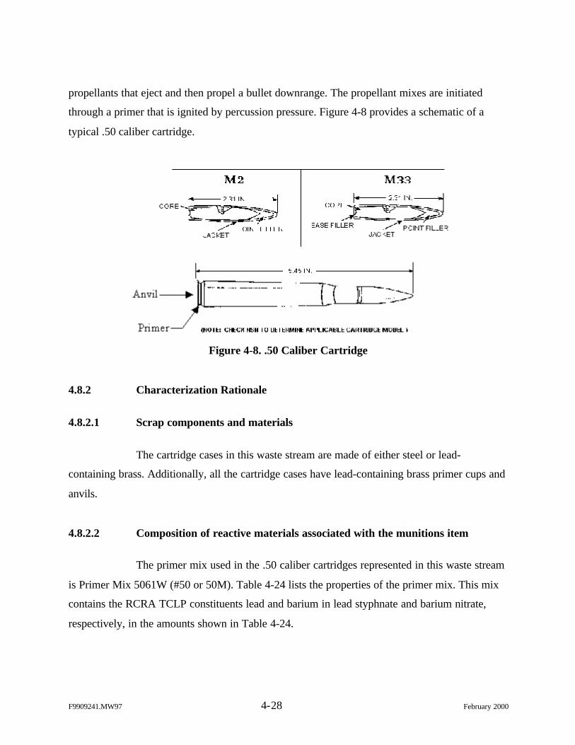
F9909241.MW97 4-28 February 2000
propellants that eject and then propel a bullet downrange. The propellant mixes are initiated
through a primer that is ignited by percussion pressure. Figure 4-8 provides a schematic of a
typical .50 caliber cartridge.
Figure 4-8. .50 Caliber Cartridge
4.8.2 Characterization Rationale
4.8.2.1 Scrap components and materials
The cartridge cases in this waste stream are made of either steel or lead-
containing brass. Additionally, all the cartridge cases have lead-containing brass primer cups and
anvils.
4.8.2.2 Composition of reactive materials associated with the munitions item
The primer mix used in the .50 caliber cartridges represented in this waste stream
is Primer Mix 5061W (#50 or 50M). Table 4-24 lists the properties of the primer mix. This mix
contains the RCRA TCLP constituents lead and barium in lead styphnate and barium nitrate,
respectively, in the amounts shown in Table 4-24.
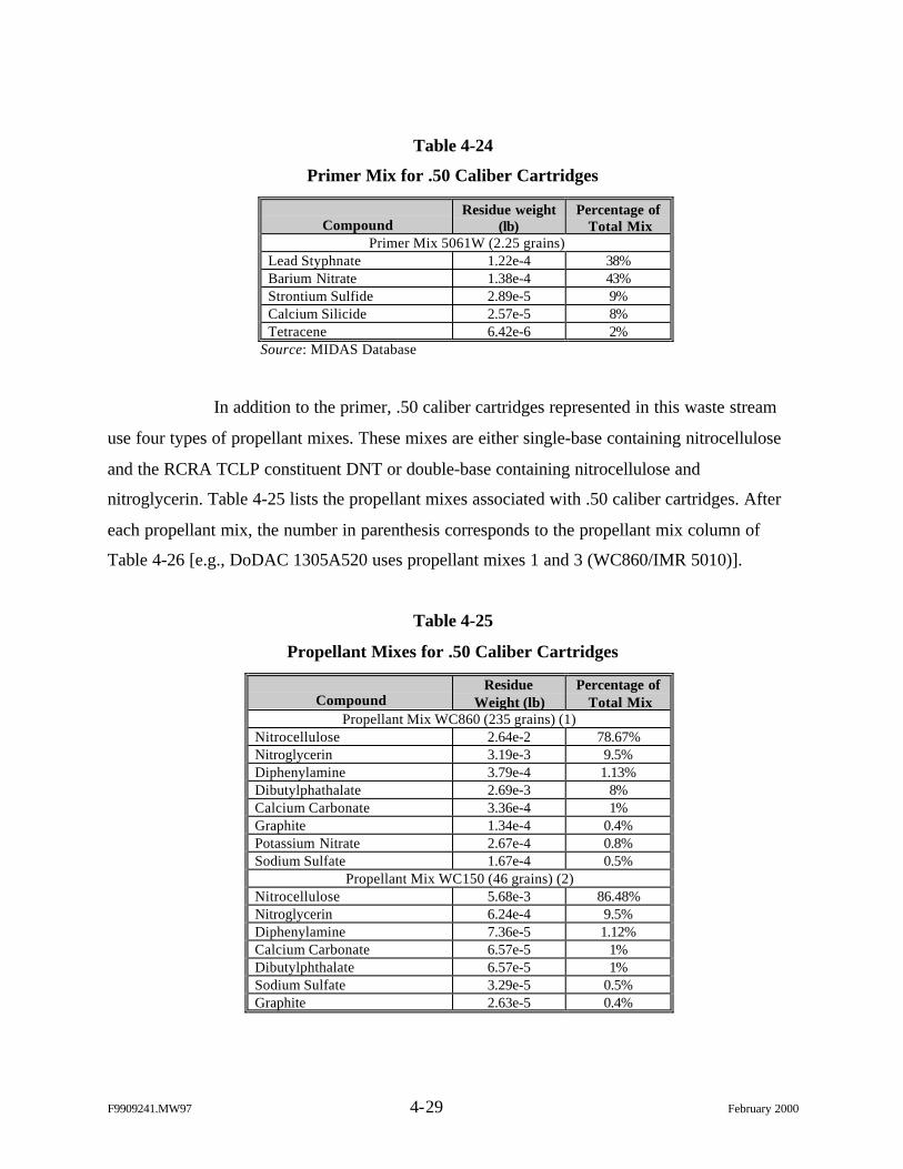
F9909241.MW97 4-29 February 2000
Table 4-24
Primer Mix for .50 Caliber Cartridges
CompoundResidue weight
(lb)Percentage of
Total MixPrimer Mix 5061W (2.25 grains)
Lead Styphnate 1.22e-4 38%Barium Nitrate 1.38e-4 43%Strontium Sulfide 2.89e-5 9%Calcium Silicide 2.57e-5 8%Tetracene 6.42e-6 2%
Source: MIDAS Database
In addition to the primer, .50 caliber cartridges represented in this waste stream
use four types of propellant mixes. These mixes are either single-base containing nitrocellulose
and the RCRA TCLP constituent DNT or double-base containing nitrocellulose and
nitroglycerin. Table 4-25 lists the propellant mixes associated with .50 caliber cartridges. After
each propellant mix, the number in parenthesis corresponds to the propellant mix column of
Table 4-26 [e.g., DoDAC 1305A520 uses propellant mixes 1 and 3 (WC860/IMR 5010)].
Table 4-25
Propellant Mixes for .50 Caliber Cartridges
CompoundResidue
Weight (lb)Percentage of
Total MixPropellant Mix WC860 (235 grains) (1)
Nitrocellulose 2.64e-2 78.67%Nitroglycerin 3.19e-3 9.5%Diphenylamine 3.79e-4 1.13%Dibutylphathalate 2.69e-3 8%Calcium Carbonate 3.36e-4 1%Graphite 1.34e-4 0.4%Potassium Nitrate 2.67e-4 0.8%Sodium Sulfate 1.67e-4 0.5%
Propellant Mix WC150 (46 grains) (2)Nitrocellulose 5.68e-3 86.48%Nitroglycerin 6.24e-4 9.5%Diphenylamine 7.36e-5 1.12%Calcium Carbonate 6.57e-5 1%Dibutylphthalate 6.57e-5 1%Sodium Sulfate 3.29e-5 0.5%Graphite 2.63e-5 0.4%
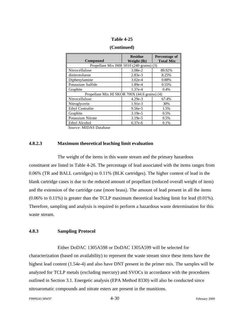
F9909241.MW97 4-30 February 2000
Table 4-25
(Continued)
CompoundResidue
Weight (lb)Percentage of
Total MixPropellant Mix IMR 5010 (240 grains) (3)
Nitrocellulose 3.08e-2 89.92%dinitrotoluene 2.83e-3 8.25%Diphenylamine 3.02e-4 0.88%Potassium Sulfide 1.89e-4 0.55%Graphite 1.37e-4 0.4%
Propellant Mix HI SKOR 700X (44.6 grains) (4)Nitrocellulose 4.29e-3 67.4%Nitroglycerin 1.91e-3 30%Ethyl Centralite 9.56e-5 1.5%Graphite 3.19e-5 0.5%Potassium Nitrate 3.19e-5 0.5%Ethyl Alcohol 6.37e-6 0.1%Source: MIDAS Database
4.8.2.3 Maximum theoretical leaching limit evaluation
The weight of the items in this waste stream and the primary hazardous
constituent are listed in Table 4-26. The percentage of lead associated with the items ranges from
0.06% (TR and BALL cartridges) to 0.11% (BLK cartridges). The higher content of lead in the
blank cartridge cases is due to the reduced amount of propellant (reduced overall weight of item)
and the extension of the cartridge case (more brass). The amount of lead present in all the items
(0.06% to 0.11%) is greater than the TCLP maximum theoretical leaching limit for lead (0.01%).
Therefore, sampling and analysis is required to perform a hazardous waste determination for this
waste stream.
4.8.3 Sampling Protocol
Either DoDAC 1305A598 or DoDAC 1305A599 will be selected for
characterization (based on availability) to represent the waste stream since these items have the
highest lead content (1.54e-4) and also have DNT present in the primer mix. The samples will be
analyzed for TCLP metals (excluding mercury) and SVOCs in accordance with the procedures
outlined in Section 3.1. Energetic analysis (EPA Method 8330) will also be conducted since
nitroaromatic compounds and nitrate esters are present in the munitions.
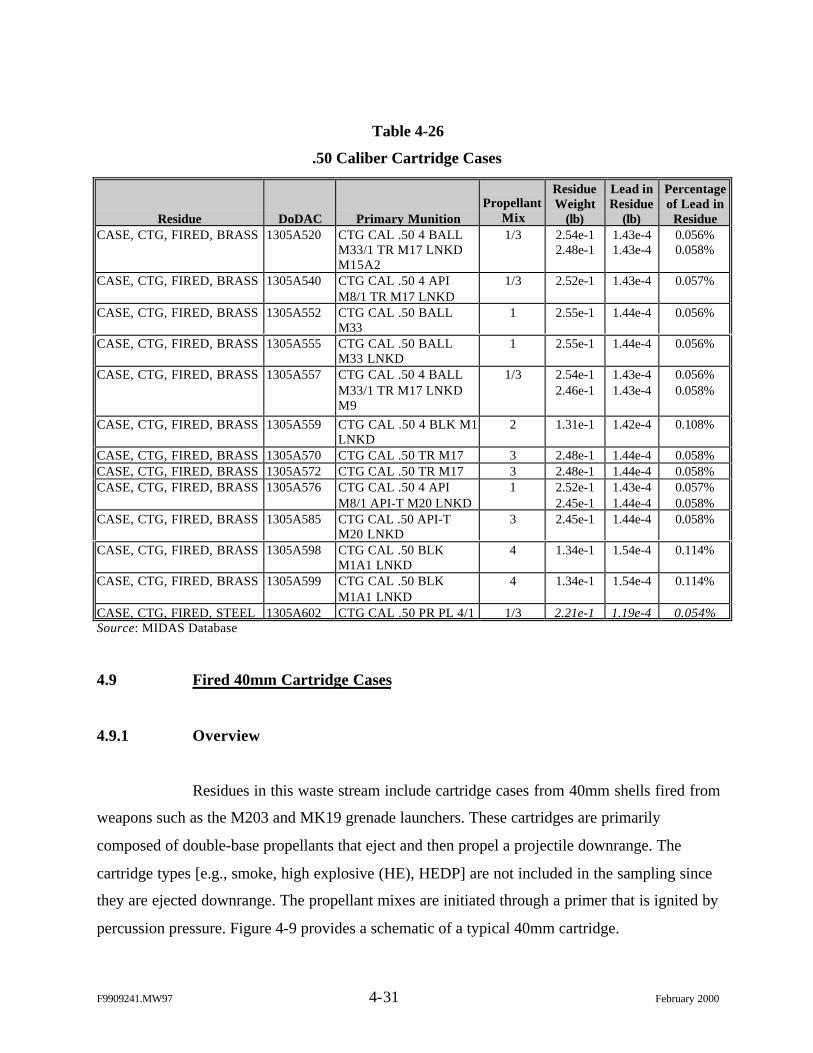
F9909241.MW97 4-31 February 2000
Table 4-26
.50 Caliber Cartridge Cases
Residue DoDAC Primary MunitionPropellant
Mix
ResidueWeight
(lb)
Lead inResidue
(lb)
Percentageof Lead in
ResidueCASE, CTG, FIRED, BRASS 1305A520 CTG CAL .50 4 BALL
M33/1 TR M17 LNKDM15A2
1/3 2.54e-12.48e-1
1.43e-41.43e-4
0.056%0.058%
CASE, CTG, FIRED, BRASS 1305A540 CTG CAL .50 4 APIM8/1 TR M17 LNKD
1/3 2.52e-1 1.43e-4 0.057%
CASE, CTG, FIRED, BRASS 1305A552 CTG CAL .50 BALLM33
1 2.55e-1 1.44e-4 0.056%
CASE, CTG, FIRED, BRASS 1305A555 CTG CAL .50 BALLM33 LNKD
1 2.55e-1 1.44e-4 0.056%
CASE, CTG, FIRED, BRASS 1305A557 CTG CAL .50 4 BALLM33/1 TR M17 LNKDM9
1/3 2.54e-12.46e-1
1.43e-41.43e-4
0.056%0.058%
CASE, CTG, FIRED, BRASS 1305A559 CTG CAL .50 4 BLK M1LNKD
2 1.31e-1 1.42e-4 0.108%
CASE, CTG, FIRED, BRASS 1305A570 CTG CAL .50 TR M17 3 2.48e-1 1.44e-4 0.058%CASE, CTG, FIRED, BRASS 1305A572 CTG CAL .50 TR M17 3 2.48e-1 1.44e-4 0.058%CASE, CTG, FIRED, BRASS 1305A576 CTG CAL .50 4 API
M8/1 API-T M20 LNKD1 2.52e-1
2.45e-11.43e-41.44e-4
0.057%0.058%
CASE, CTG, FIRED, BRASS 1305A585 CTG CAL .50 API-TM20 LNKD
3 2.45e-1 1.44e-4 0.058%
CASE, CTG, FIRED, BRASS 1305A598 CTG CAL .50 BLKM1A1 LNKD
4 1.34e-1 1.54e-4 0.114%
CASE, CTG, FIRED, BRASS 1305A599 CTG CAL .50 BLKM1A1 LNKD
4 1.34e-1 1.54e-4 0.114%
CASE, CTG, FIRED, STEEL 1305A602 CTG CAL .50 PR PL 4/1 1/3 2.21e-1 1.19e-4 0.054%Source: MIDAS Database
4.9 Fired 40mm Cartridge Cases
4.9.1 Overview
Residues in this waste stream include cartridge cases from 40mm shells fired from
weapons such as the M203 and MK19 grenade launchers. These cartridges are primarily
composed of double-base propellants that eject and then propel a projectile downrange. The
cartridge types [e.g., smoke, high explosive (HE), HEDP] are not included in the sampling since
they are ejected downrange. The propellant mixes are initiated through a primer that is ignited by
percussion pressure. Figure 4-9 provides a schematic of a typical 40mm cartridge.
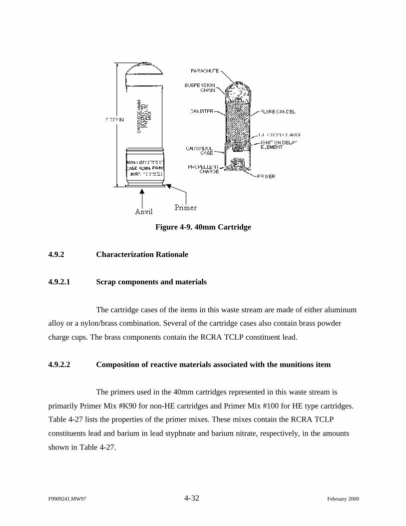
F9909241.MW97 4-32 February 2000
Figure 4-9. 40mm Cartridge
4.9.2 Characterization Rationale
4.9.2.1 Scrap components and materials
The cartridge cases of the items in this waste stream are made of either aluminum
alloy or a nylon/brass combination. Several of the cartridge cases also contain brass powder
charge cups. The brass components contain the RCRA TCLP constituent lead.
4.9.2.2 Composition of reactive materials associated with the munitions item
The primers used in the 40mm cartridges represented in this waste stream is
primarily Primer Mix #K90 for non-HE cartridges and Primer Mix #100 for HE type cartridges.
Table 4-27 lists the properties of the primer mixes. These mixes contain the RCRA TCLP
constituents lead and barium in lead styphnate and barium nitrate, respectively, in the amounts
shown in Table 4-27.
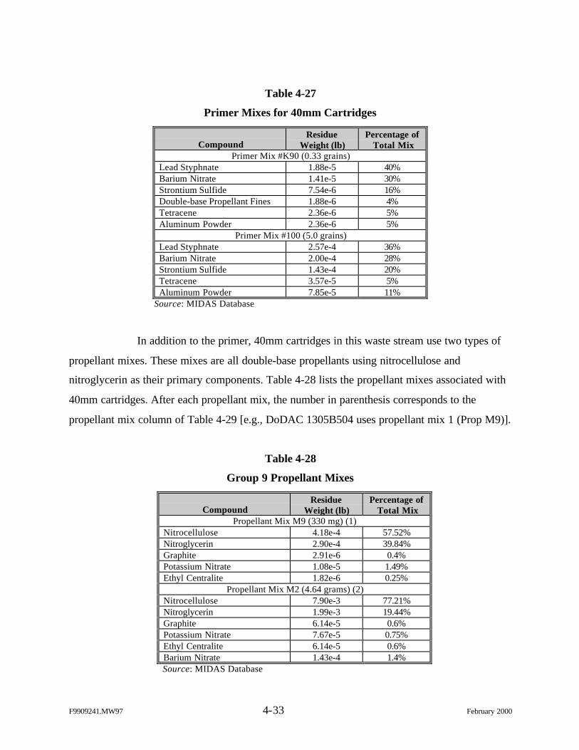
F9909241.MW97 4-33 February 2000
Table 4-27
Primer Mixes for 40mm Cartridges
CompoundResidue
Weight (lb)Percentage of
Total MixPrimer Mix #K90 (0.33 grains)
Lead Styphnate 1.88e-5 40%Barium Nitrate 1.41e-5 30%Strontium Sulfide 7.54e-6 16%Double-base Propellant Fines 1.88e-6 4%Tetracene 2.36e-6 5%Aluminum Powder 2.36e-6 5%
Primer Mix #100 (5.0 grains)Lead Styphnate 2.57e-4 36%Barium Nitrate 2.00e-4 28%Strontium Sulfide 1.43e-4 20%Tetracene 3.57e-5 5%Aluminum Powder 7.85e-5 11%
Source: MIDAS Database
In addition to the primer, 40mm cartridges in this waste stream use two types of
propellant mixes. These mixes are all double-base propellants using nitrocellulose and
nitroglycerin as their primary components. Table 4-28 lists the propellant mixes associated with
40mm cartridges. After each propellant mix, the number in parenthesis corresponds to the
propellant mix column of Table 4-29 [e.g., DoDAC 1305B504 uses propellant mix 1 (Prop M9)].
Table 4-28
Group 9 Propellant Mixes
CompoundResidue
Weight (lb)Percentage of
Total MixPropellant Mix M9 (330 mg) (1)
Nitrocellulose 4.18e-4 57.52%Nitroglycerin 2.90e-4 39.84%Graphite 2.91e-6 0.4%Potassium Nitrate 1.08e-5 1.49%Ethyl Centralite 1.82e-6 0.25%
Propellant Mix M2 (4.64 grams) (2)Nitrocellulose 7.90e-3 77.21%Nitroglycerin 1.99e-3 19.44%Graphite 6.14e-5 0.6%Potassium Nitrate 7.67e-5 0.75%Ethyl Centralite 6.14e-5 0.6%Barium Nitrate 1.43e-4 1.4%Source: MIDAS Database
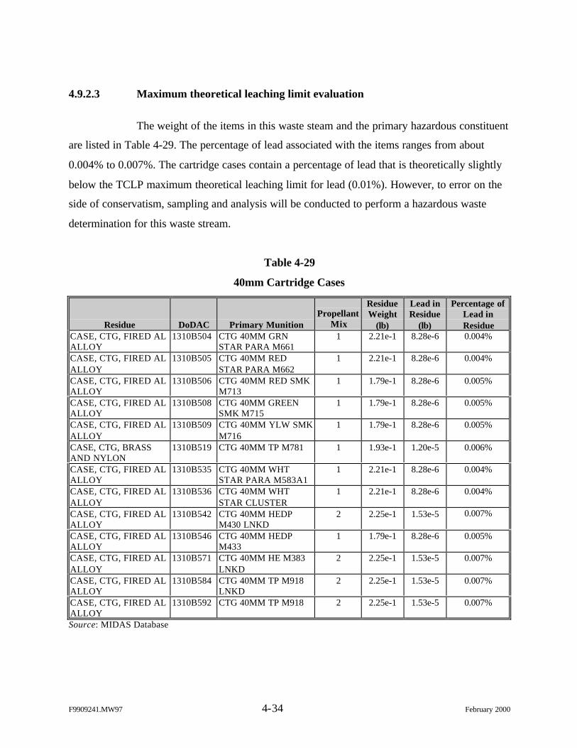
F9909241.MW97 4-34 February 2000
4.9.2.3 Maximum theoretical leaching limit evaluation
The weight of the items in this waste steam and the primary hazardous constituent
are listed in Table 4-29. The percentage of lead associated with the items ranges from about
0.004% to 0.007%. The cartridge cases contain a percentage of lead that is theoretically slightly
below the TCLP maximum theoretical leaching limit for lead (0.01%). However, to error on the
side of conservatism, sampling and analysis will be conducted to perform a hazardous waste
determination for this waste stream.
Table 4-29
40mm Cartridge Cases
Residue DoDAC Primary MunitionPropellant
Mix
ResidueWeight
(lb)
Lead inResidue
(lb)
Percentage ofLead inResidue
CASE, CTG, FIRED ALALLOY
1310B504 CTG 40MM GRNSTAR PARA M661
1 2.21e-1 8.28e-6 0.004%
CASE, CTG, FIRED ALALLOY
1310B505 CTG 40MM REDSTAR PARA M662
1 2.21e-1 8.28e-6 0.004%
CASE, CTG, FIRED ALALLOY
1310B506 CTG 40MM RED SMKM713
1 1.79e-1 8.28e-6 0.005%
CASE, CTG, FIRED ALALLOY
1310B508 CTG 40MM GREENSMK M715
1 1.79e-1 8.28e-6 0.005%
CASE, CTG, FIRED ALALLOY
1310B509 CTG 40MM YLW SMKM716
1 1.79e-1 8.28e-6 0.005%
CASE, CTG, BRASSAND NYLON
1310B519 CTG 40MM TP M781 1 1.93e-1 1.20e-5 0.006%
CASE, CTG, FIRED ALALLOY
1310B535 CTG 40MM WHTSTAR PARA M583A1
1 2.21e-1 8.28e-6 0.004%
CASE, CTG, FIRED ALALLOY
1310B536 CTG 40MM WHTSTAR CLUSTER
1 2.21e-1 8.28e-6 0.004%
CASE, CTG, FIRED ALALLOY
1310B542 CTG 40MM HEDPM430 LNKD
2 2.25e-1 1.53e-5 0.007%
CASE, CTG, FIRED ALALLOY
1310B546 CTG 40MM HEDPM433
1 1.79e-1 8.28e-6 0.005%
CASE, CTG, FIRED ALALLOY
1310B571 CTG 40MM HE M383LNKD
2 2.25e-1 1.53e-5 0.007%
CASE, CTG, FIRED ALALLOY
1310B584 CTG 40MM TP M918LNKD
2 2.25e-1 1.53e-5 0.007%
CASE, CTG, FIRED ALALLOY
1310B592 CTG 40MM TP M918 2 2.25e-1 1.53e-5 0.007%
Source: MIDAS Database
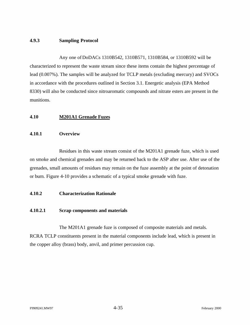
F9909241.MW97 4-35 February 2000
4.9.3 Sampling Protocol
Any one of DoDACs 1310B542, 1310B571, 1310B584, or 1310B592 will be
characterized to represent the waste stream since these items contain the highest percentage of
lead (0.007%). The samples will be analyzed for TCLP metals (excluding mercury) and SVOCs
in accordance with the procedures outlined in Section 3.1. Energetic analysis (EPA Method
8330) will also be conducted since nitroaromatic compounds and nitrate esters are present in the
munitions.
4.10 M201A1 Grenade Fuzes
4.10.1 Overview
Residues in this waste stream consist of the M201A1 grenade fuze, which is used
on smoke and chemical grenades and may be returned back to the ASP after use. After use of the
grenades, small amounts of residues may remain on the fuze assembly at the point of detonation
or burn. Figure 4-10 provides a schematic of a typical smoke grenade with fuze.
4.10.2 Characterization Rationale
4.10.2.1 Scrap components and materials
The M201A1 grenade fuze is composed of composite materials and metals.
RCRA TCLP constituents present in the material components include lead, which is present in
the copper alloy (brass) body, anvil, and primer percussion cup.
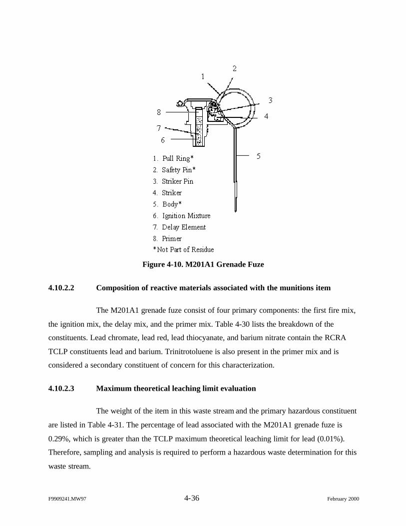
F9909241.MW97 4-36 February 2000
Figure 4-10. M201A1 Grenade Fuze
4.10.2.2 Composition of reactive materials associated with the munitions item
The M201A1 grenade fuze consist of four primary components: the first fire mix,
the ignition mix, the delay mix, and the primer mix. Table 4-30 lists the breakdown of the
constituents. Lead chromate, lead red, lead thiocyanate, and barium nitrate contain the RCRA
TCLP constituents lead and barium. Trinitrotoluene is also present in the primer mix and is
considered a secondary constituent of concern for this characterization.
4.10.2.3 Maximum theoretical leaching limit evaluation
The weight of the item in this waste stream and the primary hazardous constituent
are listed in Table 4-31. The percentage of lead associated with the M201A1 grenade fuze is
0.29%, which is greater than the TCLP maximum theoretical leaching limit for lead (0.01%).
Therefore, sampling and analysis is required to perform a hazardous waste determination for this
waste stream.
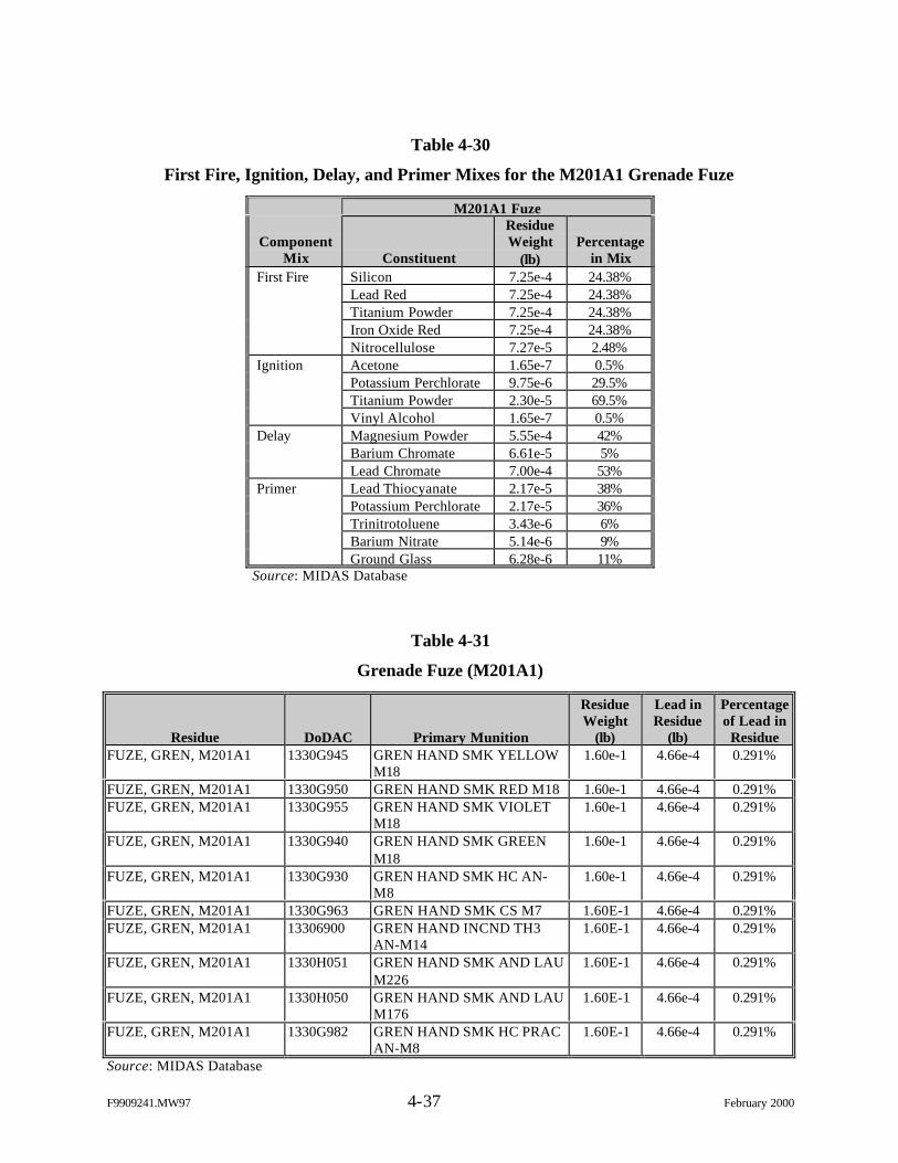
F9909241.MW97 4-37 February 2000
Table 4-30
First Fire, Ignition, Delay, and Primer Mixes for the M201A1 Grenade Fuze
M201A1 Fuze
ComponentMix Constituent
ResidueWeight
(lb)Percentage
in MixFirst Fire Silicon 7.25e-4 24.38%
Lead Red 7.25e-4 24.38%Titanium Powder 7.25e-4 24.38%Iron Oxide Red 7.25e-4 24.38%Nitrocellulose 7.27e-5 2.48%
Ignition Acetone 1.65e-7 0.5%Potassium Perchlorate 9.75e-6 29.5%Titanium Powder 2.30e-5 69.5%Vinyl Alcohol 1.65e-7 0.5%
Delay Magnesium Powder 5.55e-4 42%Barium Chromate 6.61e-5 5%Lead Chromate 7.00e-4 53%
Primer Lead Thiocyanate 2.17e-5 38%Potassium Perchlorate 2.17e-5 36%Trinitrotoluene 3.43e-6 6%Barium Nitrate 5.14e-6 9%Ground Glass 6.28e-6 11%
Source: MIDAS Database
Table 4-31
Grenade Fuze (M201A1)
Residue DoDAC Primary Munition
ResidueWeight
(lb)
Lead inResidue
(lb)
Percentageof Lead in
ResidueFUZE, GREN, M201A1 1330G945 GREN HAND SMK YELLOW
M181.60e-1 4.66e-4 0.291%
FUZE, GREN, M201A1 1330G950 GREN HAND SMK RED M18 1.60e-1 4.66e-4 0.291%FUZE, GREN, M201A1 1330G955 GREN HAND SMK VIOLET
M181.60e-1 4.66e-4 0.291%
FUZE, GREN, M201A1 1330G940 GREN HAND SMK GREENM18
1.60e-1 4.66e-4 0.291%
FUZE, GREN, M201A1 1330G930 GREN HAND SMK HC AN-M8
1.60e-1 4.66e-4 0.291%
FUZE, GREN, M201A1 1330G963 GREN HAND SMK CS M7 1.60E-1 4.66e-4 0.291%FUZE, GREN, M201A1 13306900 GREN HAND INCND TH3
AN-M141.60E-1 4.66e-4 0.291%
FUZE, GREN, M201A1 1330H051 GREN HAND SMK AND LAUM226
1.60E-1 4.66e-4 0.291%
FUZE, GREN, M201A1 1330H050 GREN HAND SMK AND LAUM176
1.60E-1 4.66e-4 0.291%
FUZE, GREN, M201A1 1330G982 GREN HAND SMK HC PRACAN-M8
1.60E-1 4.66e-4 0.291%
Source: MIDAS Database
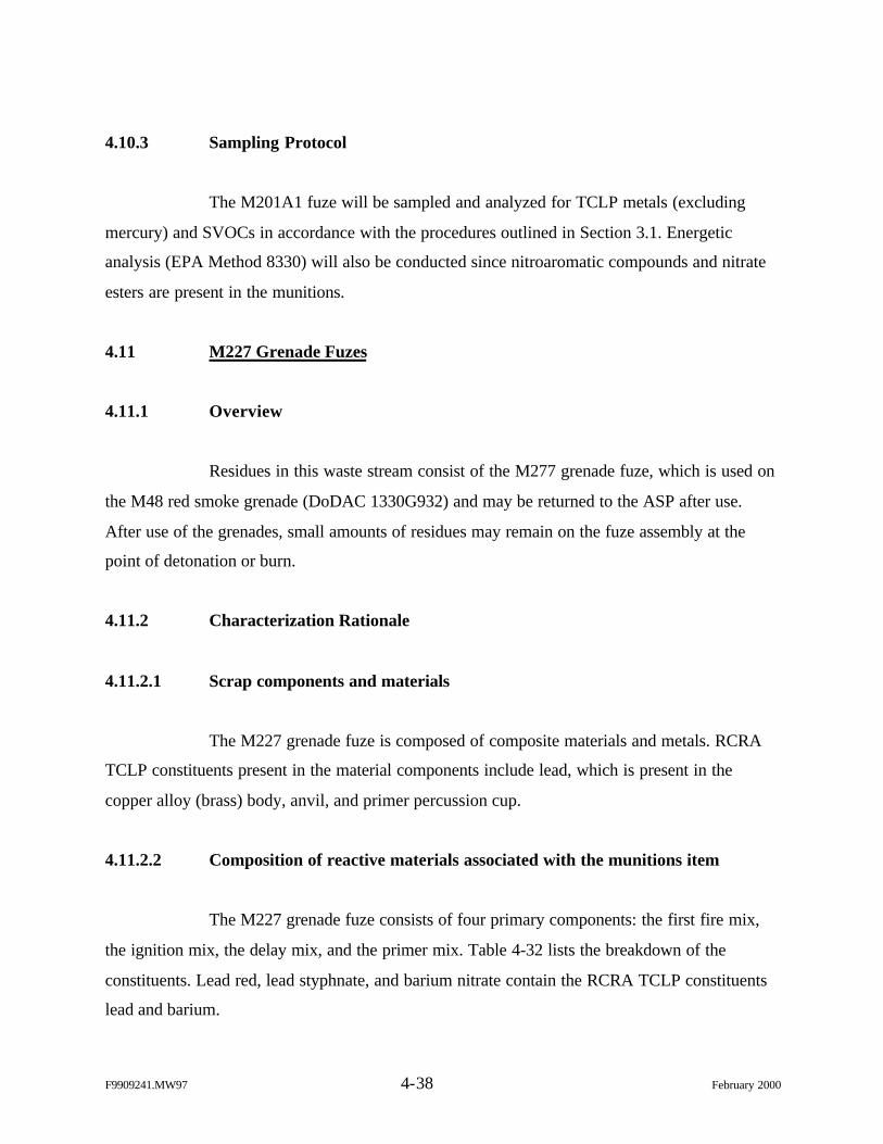
F9909241.MW97 4-38 February 2000
4.10.3 Sampling Protocol
The M201A1 fuze will be sampled and analyzed for TCLP metals (excluding
mercury) and SVOCs in accordance with the procedures outlined in Section 3.1. Energetic
analysis (EPA Method 8330) will also be conducted since nitroaromatic compounds and nitrate
esters are present in the munitions.
4.11 M227 Grenade Fuzes
4.11.1 Overview
Residues in this waste stream consist of the M277 grenade fuze, which is used on
the M48 red smoke grenade (DoDAC 1330G932) and may be returned to the ASP after use.
After use of the grenades, small amounts of residues may remain on the fuze assembly at the
point of detonation or burn.
4.11.2 Characterization Rationale
4.11.2.1 Scrap components and materials
The M227 grenade fuze is composed of composite materials and metals. RCRA
TCLP constituents present in the material components include lead, which is present in the
copper alloy (brass) body, anvil, and primer percussion cup.
4.11.2.2 Composition of reactive materials associated with the munitions item
The M227 grenade fuze consists of four primary components: the first fire mix,
the ignition mix, the delay mix, and the primer mix. Table 4-32 lists the breakdown of the
constituents. Lead red, lead styphnate, and barium nitrate contain the RCRA TCLP constituents
lead and barium.
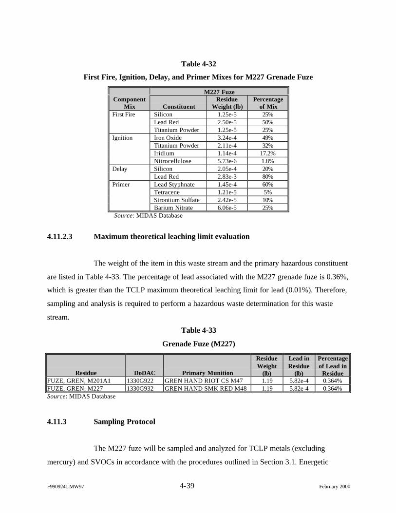
F9909241.MW97 4-39 February 2000
Table 4-32
First Fire, Ignition, Delay, and Primer Mixes for M227 Grenade Fuze
M227 FuzeComponent
Mix ConstituentResidue
Weight (lb)Percentage
of MixFirst Fire Silicon 1.25e-5 25%
Lead Red 2.50e-5 50%Titanium Powder 1.25e-5 25%
Ignition Iron Oxide 3.24e-4 49%Titanium Powder 2.11e-4 32%Iridium 1.14e-4 17.2%Nitrocellulose 5.73e-6 1.8%
Delay Silicon 2.05e-4 20%Lead Red 2.83e-3 80%
Primer Lead Styphnate 1.45e-4 60%Tetracene 1.21e-5 5%Strontium Sulfate 2.42e-5 10%Barium Nitrate 6.06e-5 25%
Source: MIDAS Database
4.11.2.3 Maximum theoretical leaching limit evaluation
The weight of the item in this waste stream and the primary hazardous constituent
are listed in Table 4-33. The percentage of lead associated with the M227 grenade fuze is 0.36%,
which is greater than the TCLP maximum theoretical leaching limit for lead (0.01%). Therefore,
sampling and analysis is required to perform a hazardous waste determination for this waste
stream.
Table 4-33
Grenade Fuze (M227)
Residue DoDAC Primary Munition
ResidueWeight
(lb)
Lead inResidue
(lb)
Percentageof Lead in
ResidueFUZE, GREN, M201A1 1330G922 GREN HAND RIOT CS M47 1.19 5.82e-4 0.364%FUZE, GREN, M227 1330G932 GREN HAND SMK RED M48 1.19 5.82e-4 0.364%Source: MIDAS Database
4.11.3 Sampling Protocol
The M227 fuze will be sampled and analyzed for TCLP metals (excluding
mercury) and SVOCs in accordance with the procedures outlined in Section 3.1. Energetic
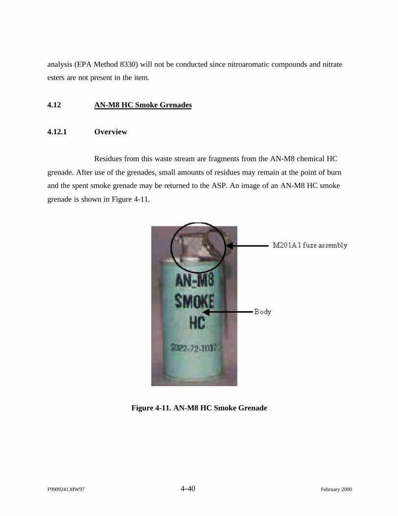
F9909241.MW97 4-40 February 2000
analysis (EPA Method 8330) will not be conducted since nitroaromatic compounds and nitrate
esters are not present in the item.
4.12 AN-M8 HC Smoke Grenades
4.12.1 Overview
Residues from this waste stream are fragments from the AN-M8 chemical HC
grenade. After use of the grenades, small amounts of residues may remain at the point of burn
and the spent smoke grenade may be returned to the ASP. An image of an AN-M8 HC smoke
grenade is shown in Figure 4-11.
Figure 4-11. AN-M8 HC Smoke Grenade
F9909241.MW97 4-41 February 2000
4.12.2 Characterization Rationale
4.12.2.1 Scrap components and materials
Lead used in the solder of the grenade may remain as part of the spent grenade
case/body returned to the issuing point or in the residual ash at the point of burn. Other
components containing lead include the brass adapter on the top assembly of the grenade.
4.12.2.2 Composition of reactive materials associated with the munitions item
The primary component in the filler of the AN-M8 smoke grenade is the RCRA
TCLP constituent HC. The fuze assembly, M201A1, is analyzed separately (Section 4.10).
Table 4-34 lists the component s of the main grenade.
Table 4-34
Filler and Solder Composition of AN-M8 Smoke Grenades
CompoundResidue
Weight (lb)Percentage of
Total MixMain Filler (480 grams)
Aluminum Powder 9.95e-2 9%Hexachloroethane 4.71e-1 44.53%Zinc Oxide 4.86e-1 46.47%
Solder (All Surface Connections) (0.03 oz.)Lead-Strontium 1.88e-3 100%Source: MIDAS Database
4.12.2.3 Maximum theoretical leaching limit evaluation
The weight of the item in this waste stream and the primary hazardous constituent
are listed in Table 4-35. The percentage of HC associated with the AN-M8 smoke grenade is
35.1%, which is greater than the TCLP maximum theoretical leaching limit for HC (0.006%).
Therefore, sampling and analysis is required to perform a hazardous waste determination for this
waste stream.
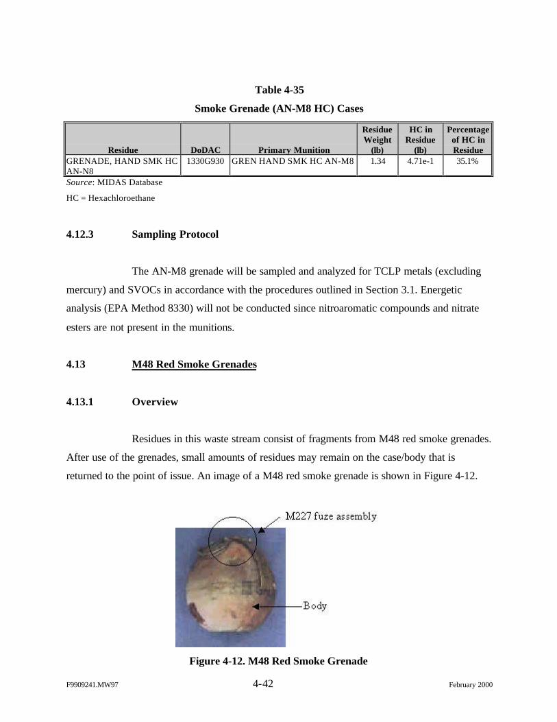
F9909241.MW97 4-42 February 2000
Table 4-35
Smoke Grenade (AN-M8 HC) Cases
Residue DoDAC Primary Munition
ResidueWeight
(lb)
HC inResidue
(lb)
Percentageof HC inResidue
GRENADE, HAND SMK HCAN-N8
1330G930 GREN HAND SMK HC AN-M8 1.34 4.71e-1 35.1%
Source: MIDAS Database
HC = Hexachloroethane
4.12.3 Sampling Protocol
The AN-M8 grenade will be sampled and analyzed for TCLP metals (excluding
mercury) and SVOCs in accordance with the procedures outlined in Section 3.1. Energetic
analysis (EPA Method 8330) will not be conducted since nitroaromatic compounds and nitrate
esters are not present in the munitions.
4.13 M48 Red Smoke Grenades
4.13.1 Overview
Residues in this waste stream consist of fragments from M48 red smoke grenades.
After use of the grenades, small amounts of residues may remain on the case/body that is
returned to the point of issue. An image of a M48 red smoke grenade is shown in Figure 4-12.
Figure 4-12. M48 Red Smoke Grenade
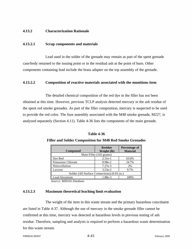
F9909241.MW97 4-43 February 2000
4.13.2 Characterization Rationale
4.13.2.1 Scrap components and materials
Lead used in the solder of the grenade may remain as part of the spent grenade
case/body returned to the issuing point or in the residual ash at the point of burn. Other
components containing lead include the brass adapter on the top assembly of the grenade.
4.13.2.2 Composition of reactive materials associated with the munitions item
The detailed chemical composition of the red dye in the filler has not been
obtained at this time. However, previous TCLP analysis detected mercury in the ash residue of
the spent red smoke grenades. As part of the filler composition, mercury is suspected to be used
to provide the red color. The fuze assembly associated with the M48 smoke grenade, M227, is
analyzed separately (Section 4.11). Table 4-36 lists the components of the main grenade.
Table 4-36
Filler and Solder Composition for M48 Red Smoke Grenades
CompoundResidue
Weight (lb)Percentage of
MaterialMain Filler (165 grams)
Dye Red 2.31e-1 63.6%Potassium Chlorate 8.98e-2 24.7%Nitrocellulose 7.27e-3 2%Lactose 3.53e-2 9.7%
Solder (All Surface Connections) (0.03 oz.)Lead-Strontium 1.88e-3 100%
Source: MIDAS Database
4.13.2.3 Maximum theoretical leaching limit evaluation
The weight of the item in this waste stream and the primary hazardous cons tituent
are listed in Table 4-37. Although the use of mercury in the smoke grenade filler cannot be
confirmed at this time, mercury was detected at hazardous levels in previous testing of ash
residue. Therefore, sampling and analysis is required to perform a hazardous waste determination
for this waste stream.
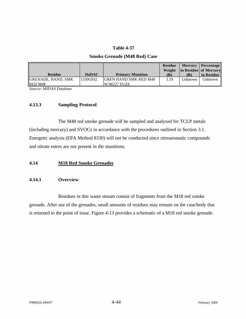
F9909241.MW97 4-44 February 2000
Table 4-37
Smoke Grenade (M48 Red) Case
Residue DoDAC Primary Munition
ResidueWeight
(lb)
Mercuryin Residue
(lb)
Percentageof Mercuryin Residue
GRENADE, HAND, SMKRED M48
1330G932 GREN HAND SMK RED M48W/M227 FUZE
1.19 Unknown Unknown
Source: MIDAS Database
4.13.3 Sampling Protocol
The M48 red smoke grenade will be sampled and analyzed for TCLP metals
(including mercury) and SVOCs in accordance with the procedures outlined in Section 3.1.
Energetic analysis (EPA Method 8330) will not be conducted since nitroaromatic compounds
and nitrate esters are not present in the munitions.
4.14 M18 Red Smoke Grenades
4.14.1 Overview
Residues in this waste stream consist of fragments from the M18 red smoke
grenade. After use of the grenades, small amounts of residues may remain on the case/body that
is returned to the point of issue. Figure 4-13 provides a schematic of a M18 red smoke grenade.
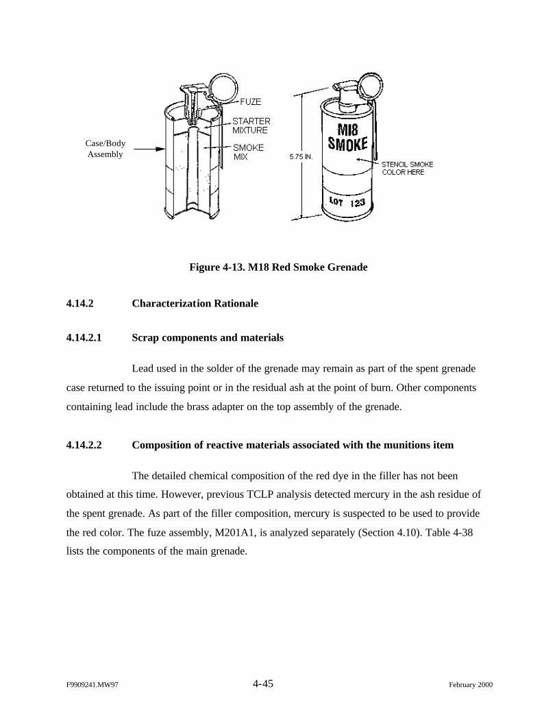
F9909241.MW97 4-45 February 2000
Figure 4-13. M18 Red Smoke Grenade
4.14.2 Characterization Rationale
4.14.2.1 Scrap components and materials
Lead used in the solder of the grenade may remain as part of the spent grenade
case returned to the issuing point or in the residual ash at the point of burn. Other components
containing lead include the brass adapter on the top assembly of the grenade.
4.14.2.2 Composition of reactive materials associated with the munitions item
The detailed chemical composition of the red dye in the filler has not been
obtained at this time. However, previous TCLP analysis detected mercury in the ash residue of
the spent grenade. As part of the filler composition, mercury is suspected to be used to provide
the red color. The fuze assembly, M201A1, is analyzed separately (Section 4.10). Table 4-38
lists the components of the main grenade.
Case/BodyAssembly
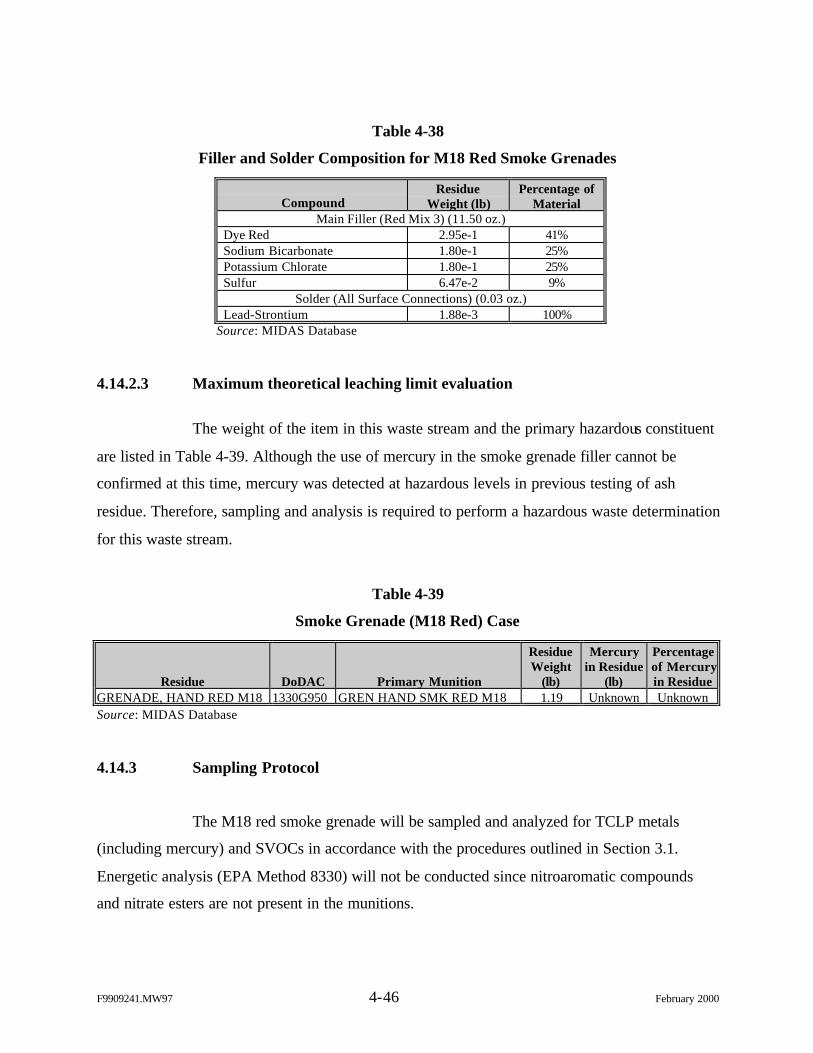
F9909241.MW97 4-46 February 2000
Table 4-38
Filler and Solder Composition for M18 Red Smoke Grenades
CompoundResidue
Weight (lb)Percentage of
MaterialMain Filler (Red Mix 3) (11.50 oz.)
Dye Red 2.95e-1 41%Sodium Bicarbonate 1.80e-1 25%Potassium Chlorate 1.80e-1 25%Sulfur 6.47e-2 9%
Solder (All Surface Connections) (0.03 oz.)Lead-Strontium 1.88e-3 100%
Source: MIDAS Database
4.14.2.3 Maximum theoretical leaching limit evaluation
The weight of the item in this waste stream and the primary hazardous constituent
are listed in Table 4-39. Although the use of mercury in the smoke grenade filler cannot be
confirmed at this time, mercury was detected at hazardous levels in previous testing of ash
residue. Therefore, sampling and analysis is required to perform a hazardous waste determination
for this waste stream.
Table 4-39
Smoke Grenade (M18 Red) Case
Residue DoDAC Primary Munition
ResidueWeight
(lb)
Mercuryin Residue
(lb)
Percentageof Mercuryin Residue
GRENADE, HAND RED M18 1330G950 GREN HAND SMK RED M18 1.19 Unknown UnknownSource: MIDAS Database
4.14.3 Sampling Protocol
The M18 red smoke grenade will be sampled and analyzed for TCLP metals
(including mercury) and SVOCs in accordance with the procedures outlined in Section 3.1.
Energetic analysis (EPA Method 8330) will not be conducted since nitroaromatic compounds
and nitrate esters are not present in the munitions.
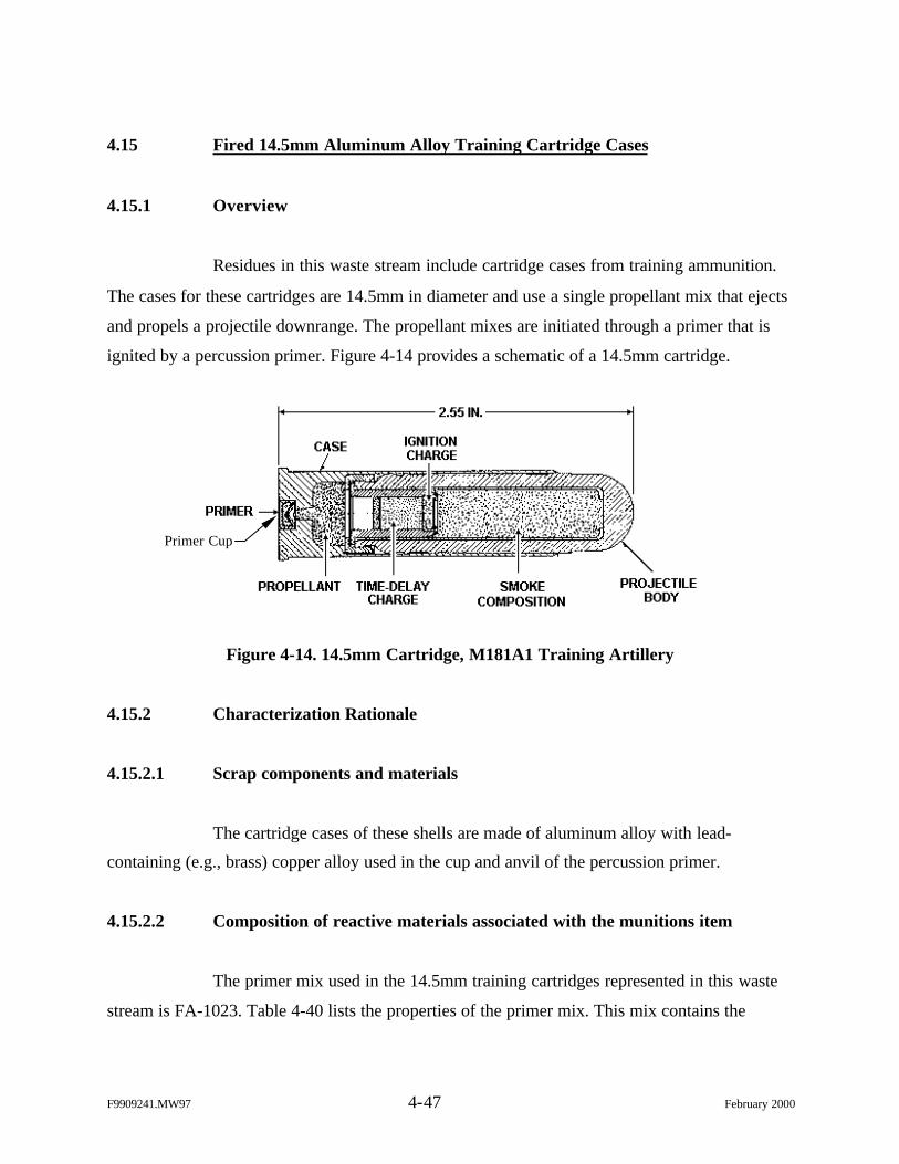
F9909241.MW97 4-47 February 2000
4.15 Fired 14.5mm Aluminum Alloy Training Cartridge Cases
4.15.1 Overview
Residues in this waste stream include cartridge cases from training ammunition.
The cases for these cartridges are 14.5mm in diameter and use a single propellant mix that ejects
and propels a projectile downrange. The propellant mixes are initiated through a primer that is
ignited by a percussion primer. Figure 4-14 provides a schematic of a 14.5mm cartridge.
Figure 4-14. 14.5mm Cartridge, M181A1 Training Artillery
4.15.2 Characterization Rationale
4.15.2.1 Scrap components and materials
The cartridge cases of these shells are made of aluminum alloy with lead-
containing (e.g., brass) copper alloy used in the cup and anvil of the percussion primer.
4.15.2.2 Composition of reactive materials associated with the munitions item
The primer mix used in the 14.5mm training cartridges represented in this waste
stream is FA-1023. Table 4-40 lists the properties of the primer mix. This mix contains the
Primer Cup
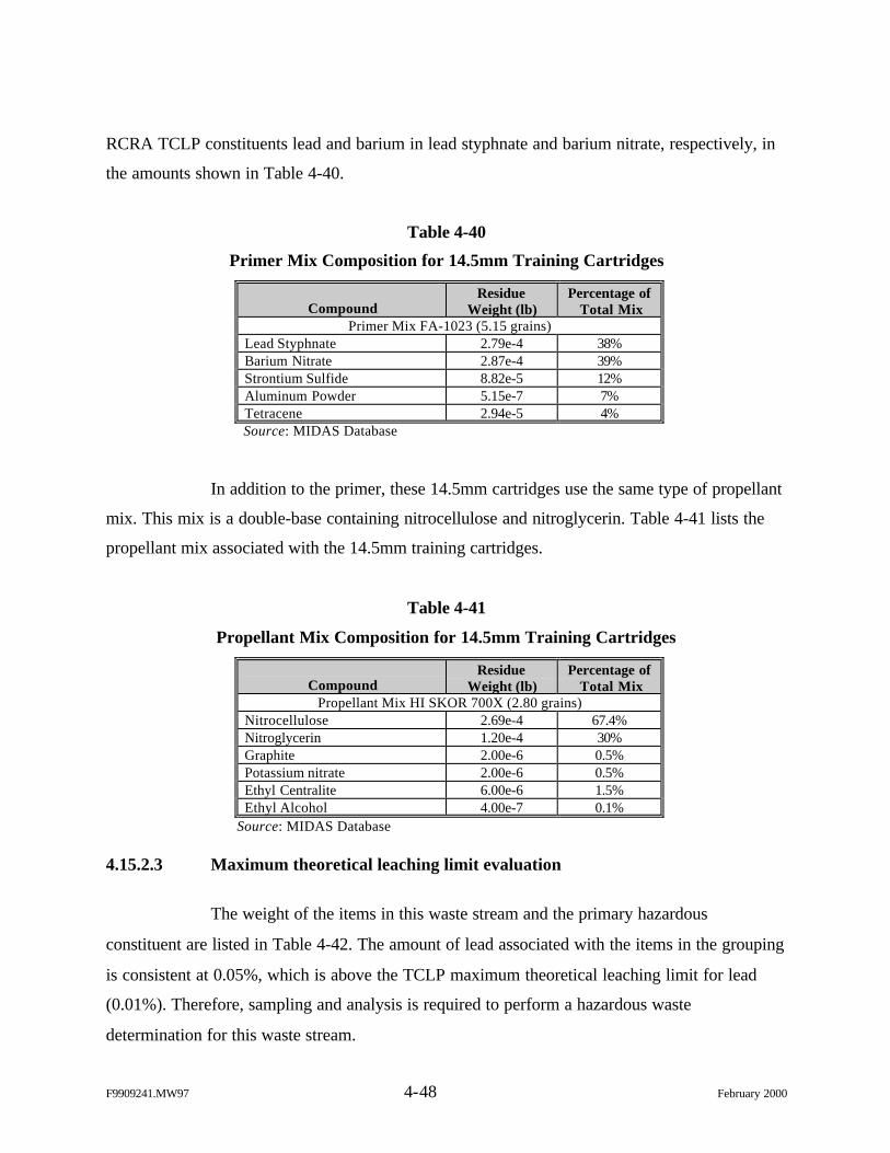
F9909241.MW97 4-48 February 2000
RCRA TCLP constituents lead and barium in lead styphnate and barium nitrate, respectively, in
the amounts shown in Table 4-40.
Table 4-40
Primer Mix Composition for 14.5mm Training Cartridges
CompoundResidue
Weight (lb)Percentage of
Total MixPrimer Mix FA-1023 (5.15 grains)
Lead Styphnate 2.79e-4 38%Barium Nitrate 2.87e-4 39%Strontium Sulfide 8.82e-5 12%Aluminum Powder 5.15e-7 7%Tetracene 2.94e-5 4%Source: MIDAS Database
In addition to the primer, these 14.5mm cartridges use the same type of propellant
mix. This mix is a double-base containing nitrocellulose and nitroglycerin. Table 4-41 lists the
propellant mix associated with the 14.5mm training cartridges.
Table 4-41
Propellant Mix Composition for 14.5mm Training Cartridges
CompoundResidue
Weight (lb)Percentage of
Total MixPropellant Mix HI SKOR 700X (2.80 grains)
Nitrocellulose 2.69e-4 67.4%Nitroglycerin 1.20e-4 30%Graphite 2.00e-6 0.5%Potassium nitrate 2.00e-6 0.5%Ethyl Centralite 6.00e-6 1.5%Ethyl Alcohol 4.00e-7 0.1%
Source: MIDAS Database
4.15.2.3 Maximum theoretical leaching limit evaluation
The weight of the items in this waste stream and the primary hazardous
constituent are listed in Table 4-42. The amount of lead associated with the items in the grouping
is consistent at 0.05%, which is above the TCLP maximum theoretical leaching limit for lead
(0.01%). Therefore, sampling and analysis is required to perform a hazardous waste
determination for this waste stream.
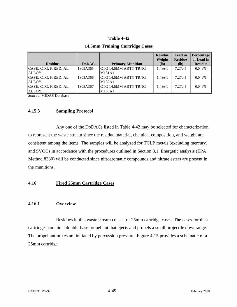
F9909241.MW97 4-49 February 2000
Table 4-42
14.5mm Training Cartridge Cases
Residue DoDAC Primary Munition
ResidueWeight
(lb)
Lead inResidue
(lb)
Percentageof Lead in
ResidueCASE, CTG, FIRED, ALALLOY
1305A365 CTG 14.5MM ARTY TRNGM181A1
1.48e-1 7.27e-5 0.049%
CASE, CTG, FIRED, ALALLOY
1305A366 CTG 14.5MM ARTY TRNGM182A1
1.48e-1 7.27e-5 0.049%
CASE, CTG, FIRED, ALALLOY
1305A367 CTG 14.5MM ARTY TRNGM183A1
1.48e-1 7.27e-5 0.049%
Source: MIDAS Database
4.15.3 Sampling Protocol
Any one of the DoDACs listed in Table 4-42 may be selected for characterization
to represent the waste stream since the residue material, chemical composition, and weight are
consistent among the items. The samples will be analyzed for TCLP metals (excluding mercury)
and SVOCs in accordance with the procedures outlined in Section 3.1. Energetic analysis (EPA
Method 8330) will be conducted since nitroaromatic compounds and nitrate esters are present in
the munitions.
4.16 Fired 25mm Cartridge Cases
4.16.1 Overview
Residues in this waste stream consist of 25mm cartridge cases. The cases for these
cartridges contain a double-base propellant that ejects and propels a small projectile downrange.
The propellant mixes are initiated by percussion pressure. Figure 4-15 provides a schematic of a
25mm cartridge.
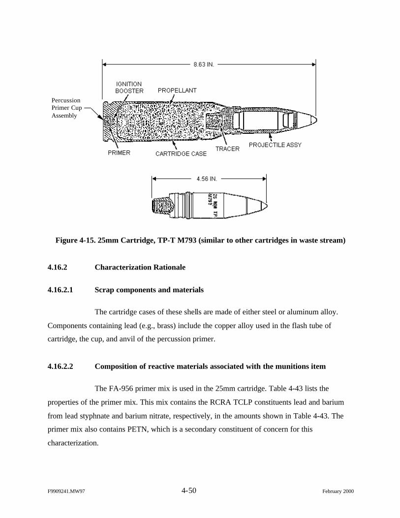
F9909241.MW97 4-50 February 2000
Figure 4-15. 25mm Cartridge, TP-T M793 (similar to other cartridges in waste stream)
4.16.2 Characterization Rationale
4.16.2.1 Scrap components and materials
The cartridge cases of these shells are made of either steel or aluminum alloy.
Components containing lead (e.g., brass) include the copper alloy used in the flash tube of
cartridge, the cup, and anvil of the percussion primer.
4.16.2.2 Composition of reactive materials associated with the munitions item
The FA-956 primer mix is used in the 25mm cartridge. Table 4-43 lists the
properties of the primer mix. This mix contains the RCRA TCLP constituents lead and barium
from lead styphnate and barium nitrate, respectively, in the amounts shown in Table 4-43. The
primer mix also contains PETN, which is a secondary constituent of concern for this
characterization.
PercussionPrimer CupAssembly
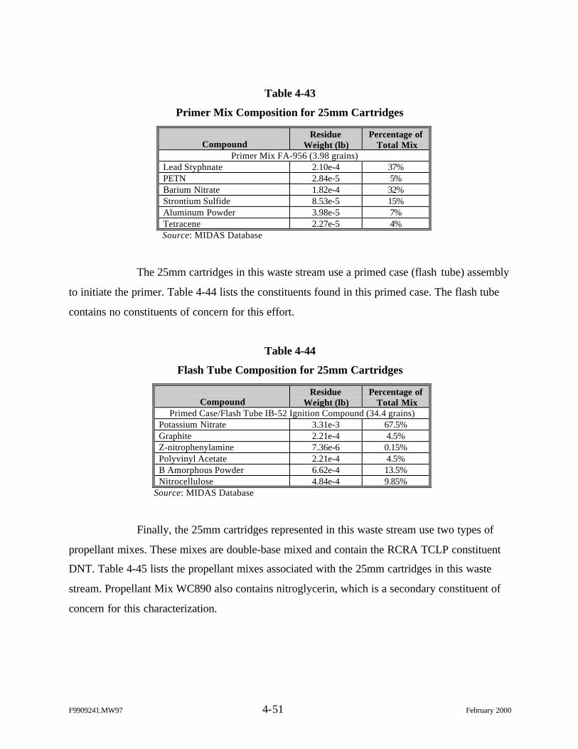
F9909241.MW97 4-51 February 2000
Table 4-43
Primer Mix Composition for 25mm Cartridges
CompoundResidue
Weight (lb)Percentage of
Total MixPrimer Mix FA-956 (3.98 grains)
Lead Styphnate 2.10e-4 37%PETN 2.84e-5 5%Barium Nitrate 1.82e-4 32%Strontium Sulfide 8.53e-5 15%Aluminum Powder 3.98e-5 7%Tetracene 2.27e-5 4%Source: MIDAS Database
The 25mm cartridges in this waste stream use a primed case (flash tube) assembly
to initiate the primer. Table 4-44 lists the constituents found in this primed case. The flash tube
contains no constituents of concern for this effort.
Table 4-44
Flash Tube Composition for 25mm Cartridges
CompoundResidue
Weight (lb)Percentage of
Total MixPrimed Case/Flash Tube IB-52 Ignition Compound (34.4 grains)
Potassium Nitrate 3.31e-3 67.5%Graphite 2.21e-4 4.5%Z-nitrophenylamine 7.36e-6 0.15%Polyvinyl Acetate 2.21e-4 4.5%B Amorphous Powder 6.62e-4 13.5%Nitrocellulose 4.84e-4 9.85%
Source: MIDAS Database
Finally, the 25mm cartridges represented in this waste stream use two types of
propellant mixes. These mixes are double-base mixed and contain the RCRA TCLP constituent
DNT. Table 4-45 lists the propellant mixes associated with the 25mm cartridges in this waste
stream. Propellant Mix WC890 also contains nitroglycerin, which is a secondary constituent of
concern for this characterization.
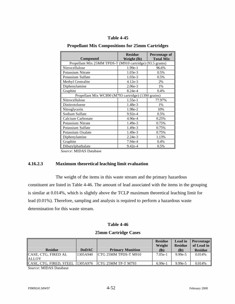
F9909241.MW97 4-52 February 2000
Table 4-45
Propellant Mix Compositions for 25mm Cartridges
CompoundResidue
Weight (lb)Percentage of
Total MixPropellant Mix 25MM TPDS-T (M910 cartridge) (93.5 grams)
Nitrocellulose 1.99e-1 96.6%Potassium Nitrate 1.03e-3 0.5%Potassium Sulfate 1.03e-3 0.5%Methyl Centralite 4.12e-3 2%Diphenylamine 2.06e-3 1%Graphite 8.24e-4 0.4%
Propellant Mix WC890 (M793 cartridge) (1390 grains)Nitrocellulose 1.55e-1 77.97%Dinitrotoluene 1.48e-3 1%Nitroglycerin 1.98e-2 10%Sodium Sulfate 9.92e-4 0.5%Calcium Carbonate 4.96e-4 0.25%Potassium Nitrate 1.49e-3 0.75%Potassium Sulfate 1.49e-3 0.75%Potassium Oxalate 1.49e-3 0.75%Diphenylamine 2.24e-3 1.13%Graphite 7.94e-4 0.4%Dibutylphathalate 9.42e-4 0.5%
Source: MIDAS Database
4.16.2.3 Maximum theoretical leaching limit evaluation
The weight of the items in this waste stream and the primary hazardous
constituent are listed in Table 4-46. The amount of lead associated with the items in the grouping
is similar at 0.014%, which is slightly above the TCLP maximum theoretical leaching limit for
lead (0.01%). Therefore, sampling and analysis is required to perform a hazardous waste
determination for this waste stream.
Table 4-46
25mm Cartridge Cases
Residue DoDAC Primary Munition
ResidueWeight
(lb)
Lead inResidue
(lb)
Percentageof Lead in
ResidueCASE, CTG, FIRED ALALLOY
1305A940 CTG 25MM TPDS-T M910 7.05e-1 9.99e-5 0.014%
CASE, CTG, FIRED, STEEL 1305A976 CTG 25MM TP-T M793 6.99e-1 9.99e-5 0.014%Source: MIDAS Database
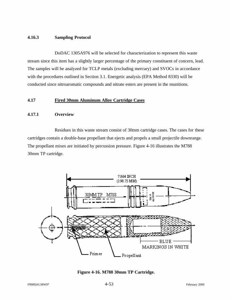
F9909241.MW97 4-53 February 2000
4.16.3 Sampling Protocol
DoDAC 1305A976 will be selected for characterization to represent this waste
stream since this item has a slightly larger percentage of the primary constituent of concern, lead.
The samples will be analyzed for TCLP metals (excluding mercury) and SVOCs in accordance
with the procedures outlined in Section 3.1. Energetic analysis (EPA Method 8330) will be
conducted since nitroaromatic compounds and nitrate esters are present in the munitions.
4.17 Fired 30mm Aluminum Alloy Cartridge Cases
4.17.1 Overview
Residues in this waste stream consist of 30mm cartridge cases. The cases for these
cartridges contain a double-base propellant that ejects and propels a small projectile downrange.
The propellant mixes are initiated by percussion pressure. Figure 4-16 illustrates the M788
30mm TP cartridge.
Figure 4-16. M788 30mm TP Cartridge.
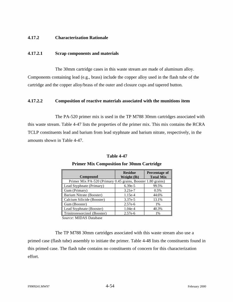
F9909241.MW97 4-54 February 2000
4.17.2 Characterization Rationale
4.17.2.1 Scrap components and materials
The 30mm cartridge cases in this waste stream are made of aluminum alloy.
Components containing lead (e.g., brass) include the copper alloy used in the flash tube of the
cartridge and the copper alloy/brass of the outer and closure cups and tapered button.
4.17.2.2 Composition of reactive materials associated with the munitions item
The PA-520 primer mix is used in the TP M788 30mm cartridges associated with
this waste stream. Table 4-47 lists the properties of the primer mix. This mix contains the RCRA
TCLP constituents lead and barium from lead styphnate and barium nitrate, respectively, in the
amounts shown in Table 4-47.
Table 4-47
Primer Mix Composition for 30mm Cartridge
CompoundResidue
Weight (lb)Percentage of
Total MixPrimer Mix PA-520 (Primary 0.45 grains, Booster 1.80 grains)
Lead Styphnate (Primary) 6.39e-5 99.5%Gum (Primary) 3.21e-7 0.5%Barium Nitrate (Booster) 1.15e-4 44.6%Calcium Silicide (Booster) 3.37e-5 13.1%Gum (Booster) 2.57e-6 1%Lead Styphnate (Booster) 1.04e-4 40.3%Trinitroresorcinol (Booster) 2.57e-6 1%
Source: MIDAS Database
The TP M788 30mm cartridges associated with this waste stream also use a
primed case (flash tube) assembly to initiate the primer. Table 4-48 lists the constituents found in
this primed case. The flash tube contains no constituents of concern for this characterization
effort.
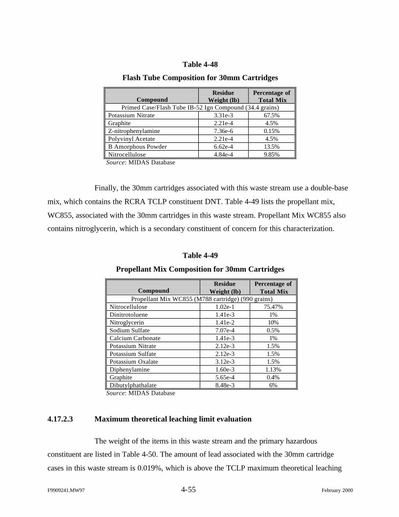
F9909241.MW97 4-55 February 2000
Table 4-48
Flash Tube Composition for 30mm Cartridges
CompoundResidue
Weight (lb)Percentage of
Total MixPrimed Case/Flash Tube IB-52 Ign Compound (34.4 grains)
Potassium Nitrate 3.31e-3 67.5%Graphite 2.21e-4 4.5%Z-nitrophenylamine 7.36e-6 0.15%Polyvinyl Acetate 2.21e-4 4.5%B Amorphous Powder 6.62e-4 13.5%Nitrocellulose 4.84e-4 9.85%
Source: MIDAS Database
Finally, the 30mm cartridges associated with this waste stream use a double-base
mix, which contains the RCRA TCLP constituent DNT. Table 4-49 lists the propellant mix,
WC855, associated with the 30mm cartridges in this waste stream. Propellant Mix WC855 also
contains nitroglycerin, which is a secondary constituent of concern for this characterization.
Table 4-49
Propellant Mix Composition for 30mm Cartridges
CompoundResidue
Weight (lb)Percentage of
Total MixPropellant Mix WC855 (M788 cartridge) (990 grains)
Nitrocellulose 1.02e-1 75.47%Dinitrotoluene 1.41e-3 1%Nitroglycerin 1.41e-2 10%Sodium Sulfate 7.07e-4 0.5%Calcium Carbonate 1.41e-3 1%Potassium Nitrate 2.12e-3 1.5%Potassium Sulfate 2.12e-3 1.5%Potassium Oxalate 3.12e-3 1.5%Diphenylamine 1.60e-3 1.13%Graphite 5.65e-4 0.4%Dibutylphathalate 8.48e-3 6%
Source: MIDAS Database
4.17.2.3 Maximum theoretical leaching limit evaluation
The weight of the items in this waste stream and the primary hazardous
constituent are listed in Table 4-50. The amount of lead associated with the 30mm cartridge
cases in this waste stream is 0.019%, which is above the TCLP maximum theoretical leaching
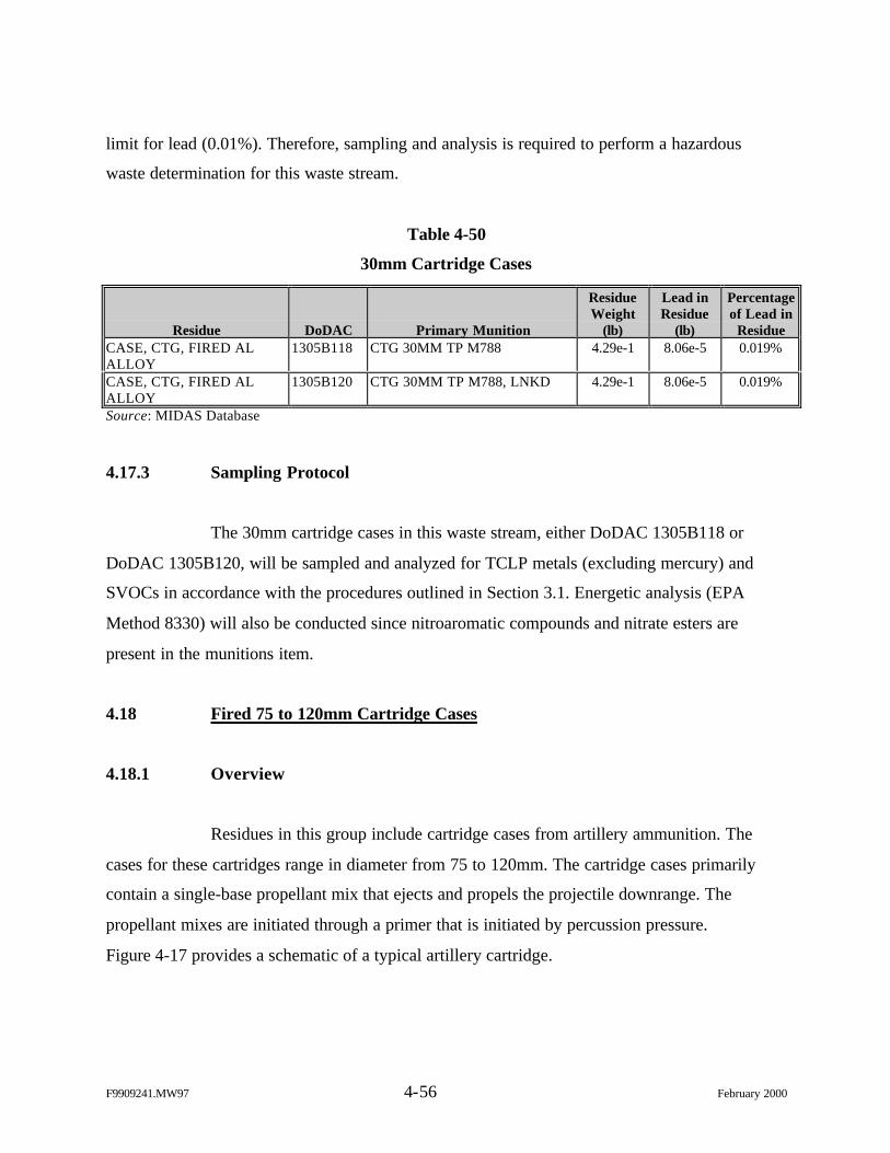
F9909241.MW97 4-56 February 2000
limit for lead (0.01%). Therefore, sampling and analysis is required to perform a hazardous
waste determination for this waste stream.
Table 4-50
30mm Cartridge Cases
Residue DoDAC Primary Munition
ResidueWeight
(lb)
Lead inResidue
(lb)
Percentageof Lead in
ResidueCASE, CTG, FIRED ALALLOY
1305B118 CTG 30MM TP M788 4.29e-1 8.06e-5 0.019%
CASE, CTG, FIRED ALALLOY
1305B120 CTG 30MM TP M788, LNKD 4.29e-1 8.06e-5 0.019%
Source: MIDAS Database
4.17.3 Sampling Protocol
The 30mm cartridge cases in this waste stream, either DoDAC 1305B118 or
DoDAC 1305B120, will be sampled and analyzed for TCLP metals (excluding mercury) and
SVOCs in accordance with the procedures outlined in Section 3.1. Energetic analysis (EPA
Method 8330) will also be conducted since nitroaromatic compounds and nitrate esters are
present in the munitions item.
4.18 Fired 75 to 120mm Cartridge Cases
4.18.1 Overview
Residues in this group include cartridge cases from artillery ammunition. The
cases for these cartridges range in diameter from 75 to 120mm. The cartridge cases primarily
contain a single-base propellant mix that ejects and propels the projectile downrange. The
propellant mixes are initiated through a primer that is initiated by percussion pressure.
Figure 4-17 provides a schematic of a typical artillery cartridge.
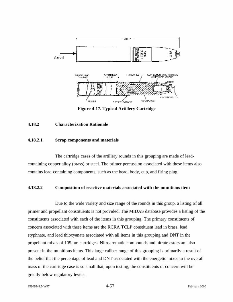
F9909241.MW97 4-57 February 2000
Figure 4-17. Typical Artillery Cartridge
4.18.2 Characterization Rationale
4.18.2.1 Scrap components and materials
The cartridge cases of the artillery rounds in this grouping are made of lead-
containing copper alloy (brass) or steel. The primer percussion associated with these items also
contains lead-containing components, such as the head, body, cup, and firing plug.
4.18.2.2 Composition of reactive materials associated with the munitions item
Due to the wide variety and size range of the rounds in this group, a listing of all
primer and propellant constituents is not provided. The MIDAS database provides a listing of the
constituents associated with each of the items in this grouping. The primary constituents of
concern associated with these items are the RCRA TCLP constituent lead in brass, lead
styphnate, and lead thiocyanate associated with all items in this grouping and DNT in the
propellant mixes of 105mm cartridges. Nitroaromatic compounds and nitrate esters are also
present in the munitions items. This large caliber range of this grouping is primarily a result of
the belief that the percentage of lead and DNT associated with the energetic mixes to the overall
mass of the cartridge case is so small that, upon testing, the constituents of concern will be
greatly below regulatory levels.
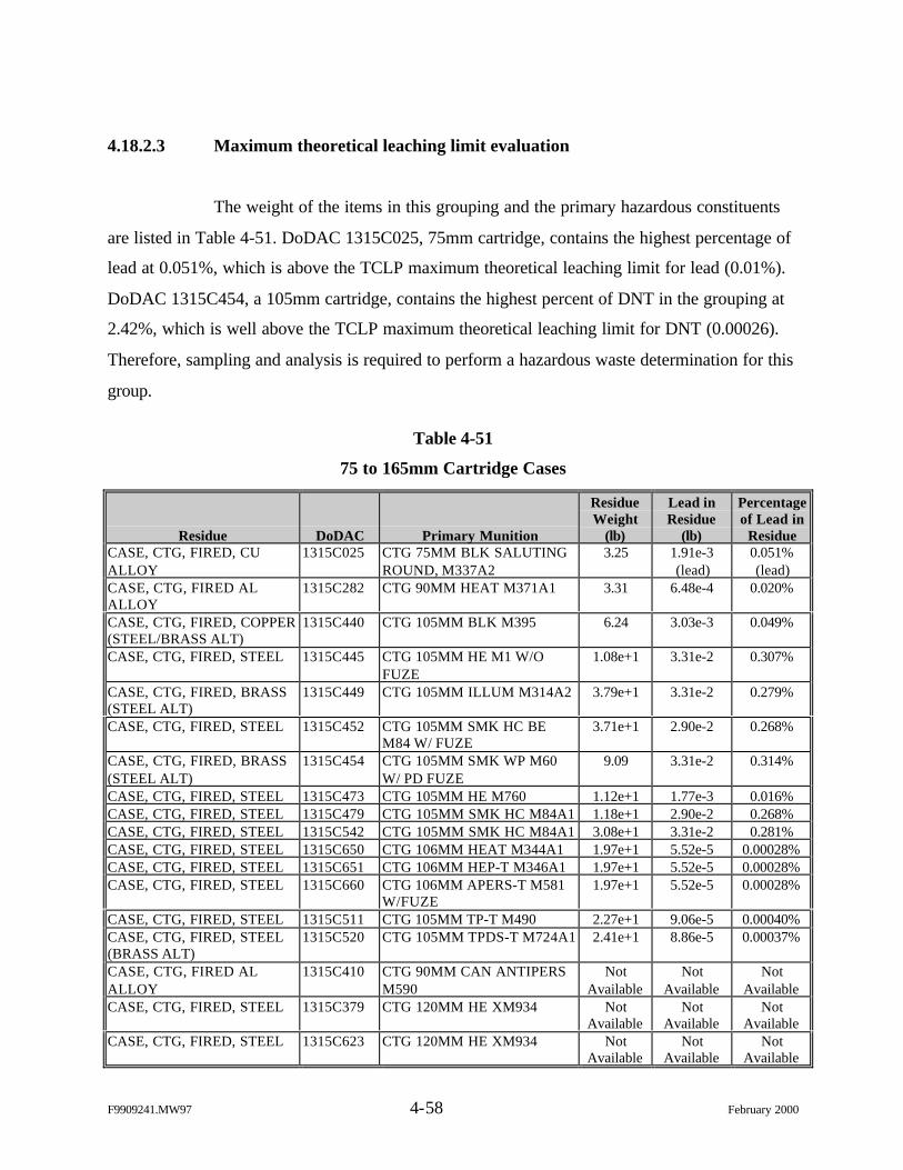
F9909241.MW97 4-58 February 2000
4.18.2.3 Maximum theoretical leaching limit evaluation
The weight of the items in this grouping and the primary hazardous constituents
are listed in Table 4-51. DoDAC 1315C025, 75mm cartridge, contains the highest percentage of
lead at 0.051%, which is above the TCLP maximum theoretical leaching limit for lead (0.01%).
DoDAC 1315C454, a 105mm cartridge, contains the highest percent of DNT in the grouping at
2.42%, which is well above the TCLP maximum theoretical leaching limit for DNT (0.00026).
Therefore, sampling and analysis is required to perform a hazardous waste determination for this
group.
Table 4-51
75 to 165mm Cartridge Cases
Residue DoDAC Primary Munition
ResidueWeight
(lb)
Lead inResidue
(lb)
Percentageof Lead in
ResidueCASE, CTG, FIRED, CUALLOY
1315C025 CTG 75MM BLK SALUTINGROUND, M337A2
3.25 1.91e-3(lead)
0.051%(lead)
CASE, CTG, FIRED ALALLOY
1315C282 CTG 90MM HEAT M371A1 3.31 6.48e-4 0.020%
CASE, CTG, FIRED, COPPER(STEEL/BRASS ALT)
1315C440 CTG 105MM BLK M395 6.24 3.03e-3 0.049%
CASE, CTG, FIRED, STEEL 1315C445 CTG 105MM HE M1 W/OFUZE
1.08e+1 3.31e-2 0.307%
CASE, CTG, FIRED, BRASS(STEEL ALT)
1315C449 CTG 105MM ILLUM M314A2 3.79e+1 3.31e-2 0.279%
CASE, CTG, FIRED, STEEL 1315C452 CTG 105MM SMK HC BEM84 W/ FUZE
3.71e+1 2.90e-2 0.268%
CASE, CTG, FIRED, BRASS(STEEL ALT)
1315C454 CTG 105MM SMK WP M60W/ PD FUZE
9.09 3.31e-2 0.314%
CASE, CTG, FIRED, STEEL 1315C473 CTG 105MM HE M760 1.12e+1 1.77e-3 0.016%CASE, CTG, FIRED, STEEL 1315C479 CTG 105MM SMK HC M84A1 1.18e+1 2.90e-2 0.268%CASE, CTG, FIRED, STEEL 1315C542 CTG 105MM SMK HC M84A1 3.08e+1 3.31e-2 0.281%CASE, CTG, FIRED, STEEL 1315C650 CTG 106MM HEAT M344A1 1.97e+1 5.52e-5 0.00028%CASE, CTG, FIRED, STEEL 1315C651 CTG 106MM HEP-T M346A1 1.97e+1 5.52e-5 0.00028%CASE, CTG, FIRED, STEEL 1315C660 CTG 106MM APERS-T M581
W/FUZE1.97e+1 5.52e-5 0.00028%
CASE, CTG, FIRED, STEEL 1315C511 CTG 105MM TP-T M490 2.27e+1 9.06e-5 0.00040%CASE, CTG, FIRED, STEEL(BRASS ALT)
1315C520 CTG 105MM TPDS-T M724A1 2.41e+1 8.86e-5 0.00037%
CASE, CTG, FIRED ALALLOY
1315C410 CTG 90MM CAN ANTIPERSM590
NotAvailable
NotAvailable
NotAvailable
CASE, CTG, FIRED, STEEL 1315C379 CTG 120MM HE XM934 NotAvailable
NotAvailable
NotAvailable
CASE, CTG, FIRED, STEEL 1315C623 CTG 120MM HE XM934 NotAvailable
NotAvailable
NotAvailable
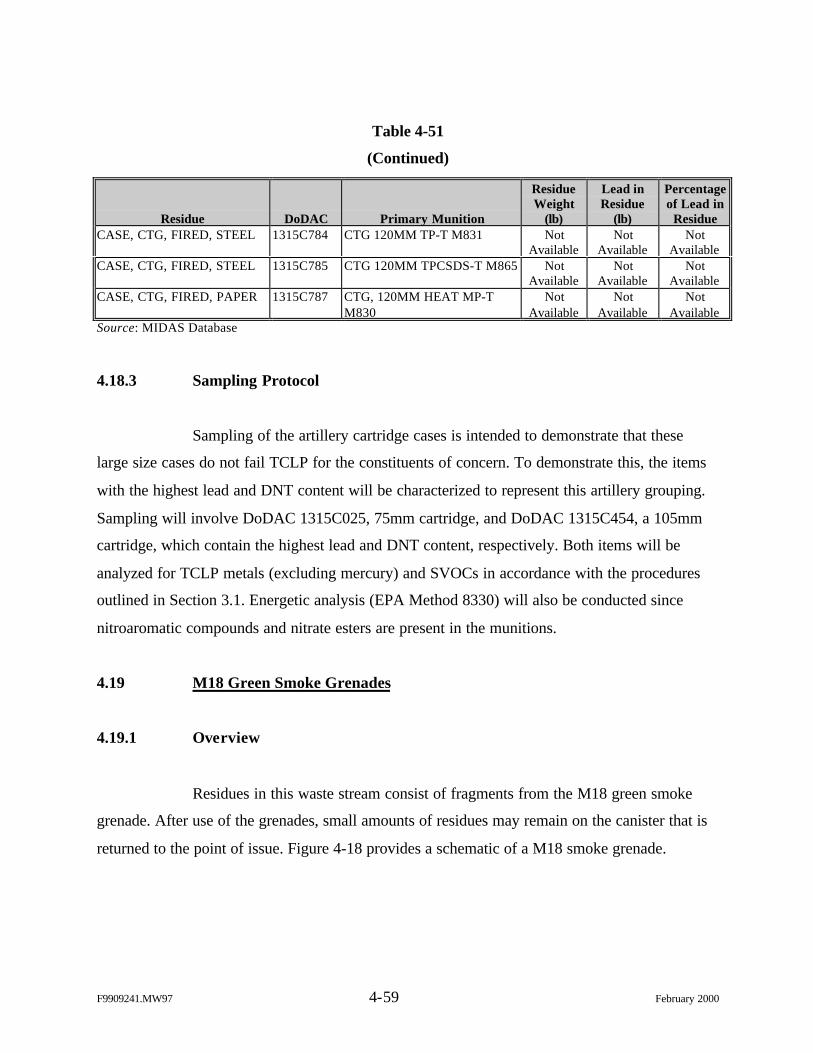
F9909241.MW97 4-59 February 2000
Table 4-51
(Continued)
Residue DoDAC Primary Munition
ResidueWeight
(lb)
Lead inResidue
(lb)
Percentageof Lead in
ResidueCASE, CTG, FIRED, STEEL 1315C784 CTG 120MM TP-T M831 Not
AvailableNot
AvailableNot
AvailableCASE, CTG, FIRED, STEEL 1315C785 CTG 120MM TPCSDS-T M865 Not
AvailableNot
AvailableNot
AvailableCASE, CTG, FIRED, PAPER 1315C787 CTG, 120MM HEAT MP-T
M830Not
AvailableNot
AvailableNot
AvailableSource: MIDAS Database
4.18.3 Sampling Protocol
Sampling of the artillery cartridge cases is intended to demonstrate that these
large size cases do not fail TCLP for the constituents of concern. To demonstrate this, the items
with the highest lead and DNT content will be characterized to represent this artillery grouping.
Sampling will involve DoDAC 1315C025, 75mm cartridge, and DoDAC 1315C454, a 105mm
cartridge, which contain the highest lead and DNT content, respectively. Both items will be
analyzed for TCLP metals (excluding mercury) and SVOCs in accordance with the procedures
outlined in Section 3.1. Energetic analysis (EPA Method 8330) will also be conducted since
nitroaromatic compounds and nitrate esters are present in the munitions.
4.19 M18 Green Smoke Grenades
4.19.1 Overview
Residues in this waste stream consist of fragments from the M18 green smoke
grenade. After use of the grenades, small amounts of residues may remain on the canister that is
returned to the point of issue. Figure 4-18 provides a schematic of a M18 smoke grenade.
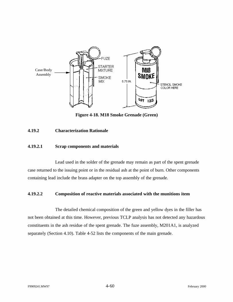
F9909241.MW97 4-60 February 2000
Figure 4-18. M18 Smoke Grenade (Green)
4.19.2 Characterization Rationale
4.19.2.1 Scrap components and materials
Lead used in the solder of the grenade may remain as part of the spent grenade
case returned to the issuing point or in the residual ash at the point of burn. Other components
containing lead include the brass adapter on the top assembly of the grenade.
4.19.2.2 Composition of reactive materials associated with the munitions item
The detailed chemical composition of the green and yellow dyes in the filler has
not been obtained at this time. However, previous TCLP analysis has not detected any hazardous
constituents in the ash residue of the spent grenade. The fuze assembly, M201A1, is analyzed
separately (Section 4.10). Table 4-52 lists the components of the main grenade.
Case/BodyAssembly
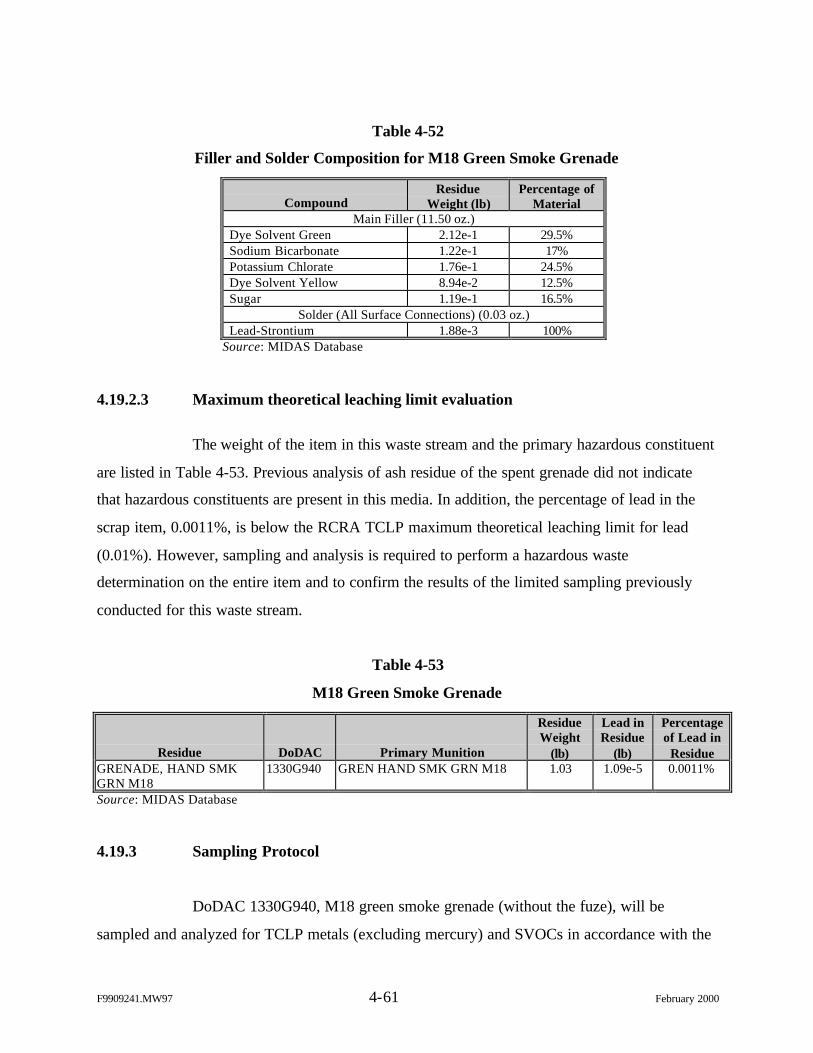
F9909241.MW97 4-61 February 2000
Table 4-52
Filler and Solder Composition for M18 Green Smoke Grenade
CompoundResidue
Weight (lb)Percentage of
MaterialMain Filler (11.50 oz.)
Dye Solvent Green 2.12e-1 29.5%Sodium Bicarbonate 1.22e-1 17%Potassium Chlorate 1.76e-1 24.5%Dye Solvent Yellow 8.94e-2 12.5%Sugar 1.19e-1 16.5%
Solder (All Surface Connections) (0.03 oz.)Lead-Strontium 1.88e-3 100%
Source: MIDAS Database
4.19.2.3 Maximum theoretical leaching limit evaluation
The weight of the item in this waste stream and the primary hazardous constituent
are listed in Table 4-53. Previous analysis of ash residue of the spent grenade did not indicate
that hazardous constituents are present in this media. In addition, the percentage of lead in the
scrap item, 0.0011%, is below the RCRA TCLP maximum theoretical leaching limit for lead
(0.01%). However, sampling and analysis is required to perform a hazardous waste
determination on the entire item and to confirm the results of the limited sampling previously
conducted for this waste stream.
Table 4-53
M18 Green Smoke Grenade
Residue DoDAC Primary Munition
ResidueWeight
(lb)
Lead inResidue
(lb)
Percentageof Lead in
ResidueGRENADE, HAND SMKGRN M18
1330G940 GREN HAND SMK GRN M18 1.03 1.09e-5 0.0011%
Source: MIDAS Database
4.19.3 Sampling Protocol
DoDAC 1330G940, M18 green smoke grenade (without the fuze), will be
sampled and analyzed for TCLP metals (excluding mercury) and SVOCs in accordance with the
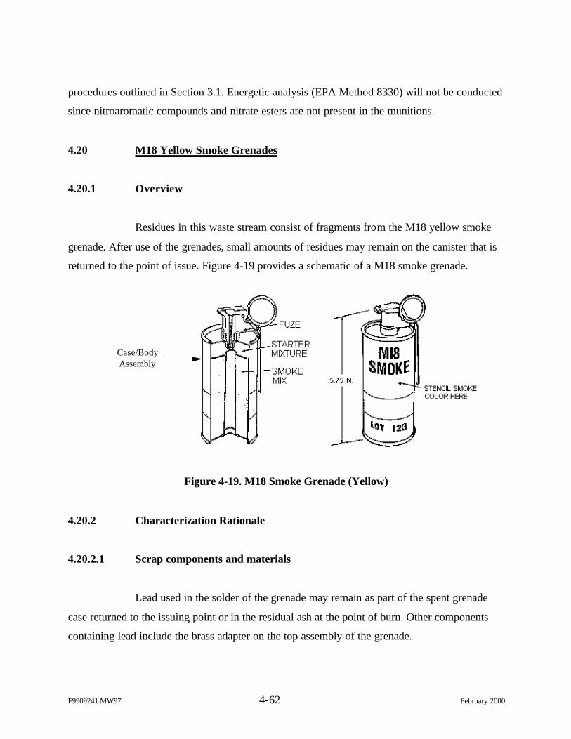
F9909241.MW97 4-62 February 2000
procedures outlined in Section 3.1. Energetic analysis (EPA Method 8330) will not be conducted
since nitroaromatic compounds and nitrate esters are not present in the munitions.
4.20 M18 Yellow Smoke Grenades
4.20.1 Overview
Residues in this waste stream consist of fragments from the M18 yellow smoke
grenade. After use of the grenades, small amounts of residues may remain on the canister that is
returned to the point of issue. Figure 4-19 provides a schematic of a M18 smoke grenade.
Figure 4-19. M18 Smoke Grenade (Yellow)
4.20.2 Characterization Rationale
4.20.2.1 Scrap components and materials
Lead used in the solder of the grenade may remain as part of the spent grenade
case returned to the issuing point or in the residual ash at the point of burn. Other components
containing lead include the brass adapter on the top assembly of the grenade.
Case/BodyAssembly
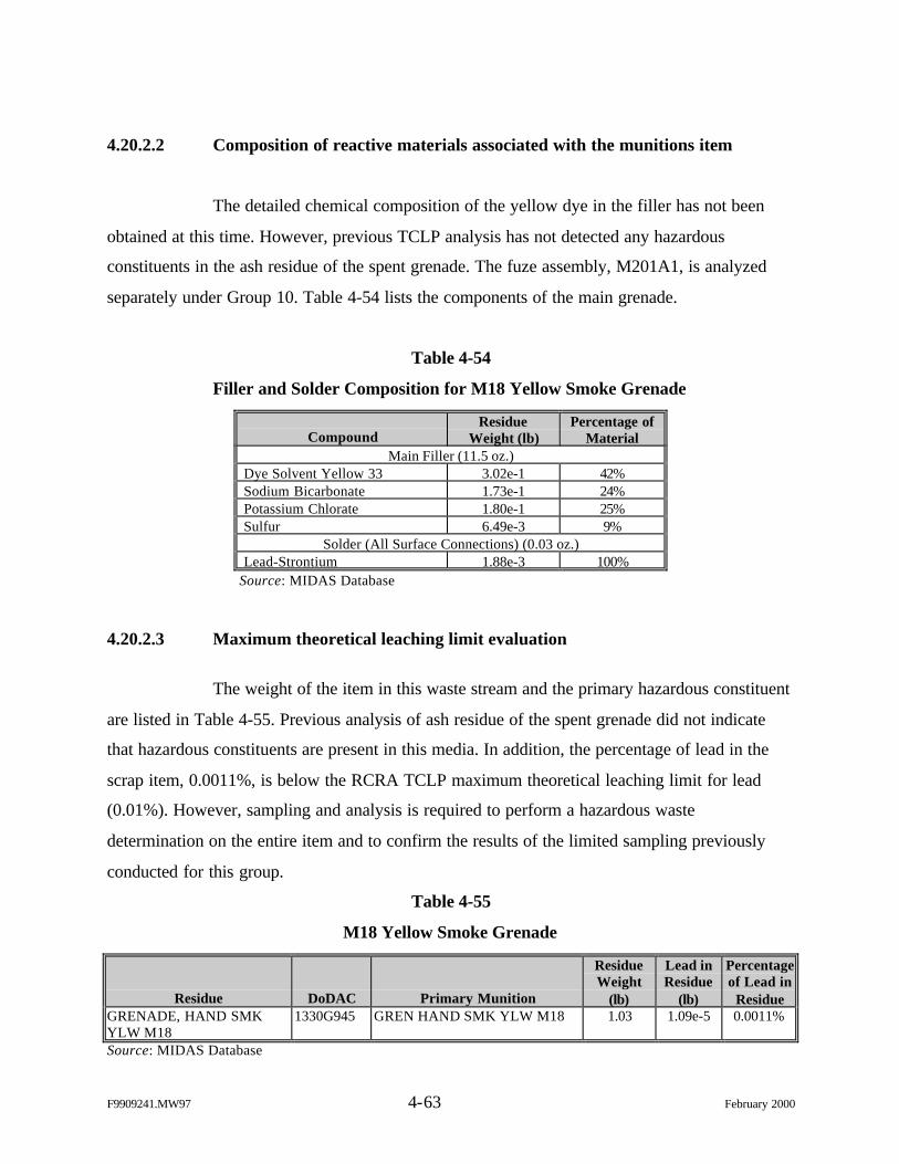
F9909241.MW97 4-63 February 2000
4.20.2.2 Composition of reactive materials associated with the munitions item
The detailed chemical composition of the yellow dye in the filler has not been
obtained at this time. However, previous TCLP analysis has not detected any hazardous
constituents in the ash residue of the spent grenade. The fuze assembly, M201A1, is analyzed
separately under Group 10. Table 4-54 lists the components of the main grenade.
Table 4-54
Filler and Solder Composition for M18 Yellow Smoke Grenade
CompoundResidue
Weight (lb)Percentage of
MaterialMain Filler (11.5 oz.)
Dye Solvent Yellow 33 3.02e-1 42%Sodium Bicarbonate 1.73e-1 24%Potassium Chlorate 1.80e-1 25%Sulfur 6.49e-3 9%
Solder (All Surface Connections) (0.03 oz.)Lead-Strontium 1.88e-3 100%
Source: MIDAS Database
4.20.2.3 Maximum theoretical leaching limit evaluation
The weight of the item in this waste stream and the primary hazardous constituent
are listed in Table 4-55. Previous analysis of ash residue of the spent grenade did not indicate
that hazardous constituents are present in this media. In addition, the percentage of lead in the
scrap item, 0.0011%, is below the RCRA TCLP maximum theoretical leaching limit for lead
(0.01%). However, sampling and analysis is required to perform a hazardous waste
determination on the entire item and to confirm the results of the limited sampling previously
conducted for this group.
Table 4-55
M18 Yellow Smoke Grenade
Residue DoDAC Primary Munition
ResidueWeight
(lb)
Lead inResidue
(lb)
Percentageof Lead in
ResidueGRENADE, HAND SMKYLW M18
1330G945 GREN HAND SMK YLW M18 1.03 1.09e-5 0.0011%
Source: MIDAS Database
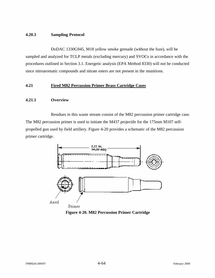
F9909241.MW97 4-64 February 2000
4.20.3 Sampling Protocol
DoDAC 1330G945, M18 yellow smoke grenade (without the fuze), will be
sampled and analyzed for TCLP metals (excluding mercury) and SVOCs in accordance with the
procedures outlined in Section 3.1. Energetic analysis (EPA Method 8330) will not be conducted
since nitroaromatic compounds and nitrate esters are not present in the munitions.
4.21 Fired M82 Percussion Primer Brass Cartridge Cases
4.21.1 Overview
Residues in this waste stream consist of the M82 percussion primer cartridge case.
The M82 percussion primer is used to initiate the M437 projectile for the 175mm M107 self-
propelled gun used by field artillery. Figure 4-20 provides a schematic of the M82 percussion
primer cartridge.
Figure 4-20. M82 Percussion Primer Cartridge
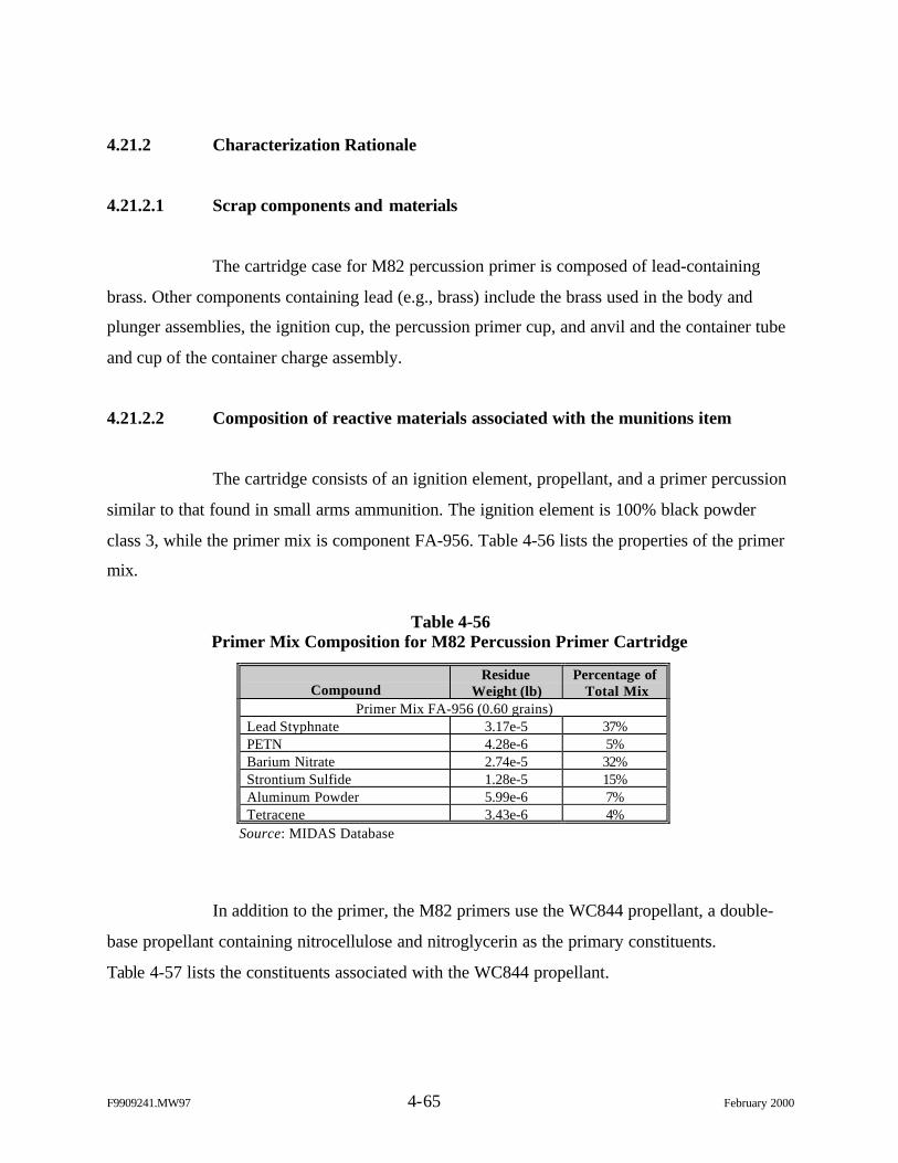
F9909241.MW97 4-65 February 2000
4.21.2 Characterization Rationale
4.21.2.1 Scrap components and materials
The cartridge case for M82 percussion primer is composed of lead-containing
brass. Other components containing lead (e.g., brass) include the brass used in the body and
plunger assemblies, the ignition cup, the percussion primer cup, and anvil and the container tube
and cup of the container charge assembly.
4.21.2.2 Composition of reactive materials associated with the munitions item
The cartridge consists of an ignition element, propellant, and a primer percussion
similar to that found in small arms ammunition. The ignition element is 100% black powder
class 3, while the primer mix is component FA-956. Table 4-56 lists the properties of the primer
mix.
Table 4-56Primer Mix Composition for M82 Percussion Primer Cartridge
CompoundResidue
Weight (lb)Percentage of
Total MixPrimer Mix FA-956 (0.60 grains)
Lead Styphnate 3.17e-5 37%PETN 4.28e-6 5%Barium Nitrate 2.74e-5 32%Strontium Sulfide 1.28e-5 15%Aluminum Powder 5.99e-6 7%Tetracene 3.43e-6 4%
Source: MIDAS Database
In addition to the primer, the M82 primers use the WC844 propellant, a double-
base propellant containing nitrocellulose and nitroglycerin as the primary constituents.
Table 4-57 lists the constituents associated with the WC844 propellant.
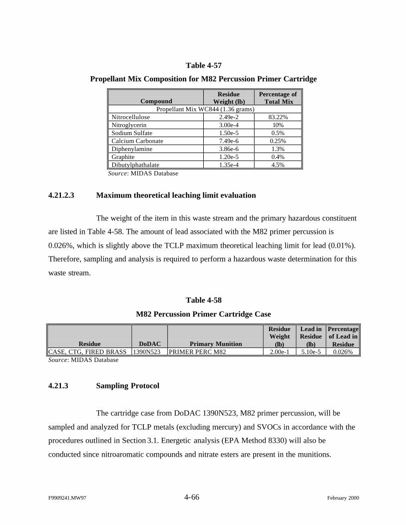
F9909241.MW97 4-66 February 2000
Table 4-57
Propellant Mix Composition for M82 Percussion Primer Cartridge
CompoundResidue
Weight (lb)Percentage of
Total MixPropellant Mix WC844 (1.36 grams)
Nitrocellulose 2.49e-2 83.22%Nitroglycerin 3.00e-4 10%Sodium Sulfate 1.50e-5 0.5%Calcium Carbonate 7.49e-6 0.25%Diphenylamine 3.86e-6 1.3%Graphite 1.20e-5 0.4%Dibutylphathalate 1.35e-4 4.5%
Source: MIDAS Database
4.21.2.3 Maximum theoretical leaching limit evaluation
The weight of the item in this waste stream and the primary hazardous constituent
are listed in Table 4-58. The amount of lead associated with the M82 primer percussion is
0.026%, which is slightly above the TCLP maximum theoretical leaching limit for lead (0.01%).
Therefore, sampling and analysis is required to perform a hazardous waste determination for this
waste stream.
Table 4-58
M82 Percussion Primer Cartridge Case
Residue DoDAC Primary Munition
ResidueWeight
(lb)
Lead inResidue
(lb)
Percentageof Lead in
ResidueCASE, CTG, FIRED BRASS 1390N523 PRIMER PERC M82 2.00e-1 5.10e-5 0.026%Source: MIDAS Database
4.21.3 Sampling Protocol
The cartridge case from DoDAC 1390N523, M82 primer percussion, will be
sampled and analyzed for TCLP metals (excluding mercury) and SVOCs in accordance with the
procedures outlined in Section 3.1. Energetic analysis (EPA Method 8330) will also be
conducted since nitroaromatic compounds and nitrate esters are present in the munitions.
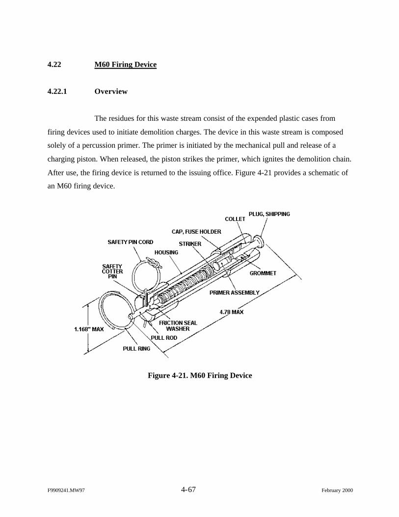
F9909241.MW97 4-67 February 2000
4.22 M60 Firing Device
4.22.1 Overview
The residues for this waste stream consist of the expended plastic cases from
firing devices used to initiate demolition charges. The device in this waste stream is composed
solely of a percussion primer. The primer is initiated by the mechanical pull and release of a
charging piston. When released, the piston strikes the primer, which ignites the demolition chain.
After use, the firing device is returned to the issuing office. Figure 4-21 provides a schematic of
an M60 firing device.
Figure 4-21. M60 Firing Device
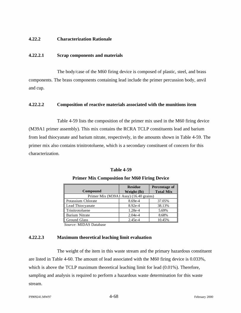
F9909241.MW97 4-68 February 2000
4.22.2 Characterization Rationale
4.22.2.1 Scrap components and materials
The body/case of the M60 firing device is composed of plastic, steel, and brass
components. The brass components containing lead include the primer percussion body, anvil
and cup.
4.22.2.2 Composition of reactive materials associated with the munitions item
Table 4-59 lists the composition of the primer mix used in the M60 firing device
(M39A1 primer assembly). This mix contains the RCRA TCLP constituents lead and barium
from lead thiocyanate and barium nitrate, respectively, in the amounts shown in Table 4-59. The
primer mix also contains trinitrotoluene, which is a secondary constituent of concern for this
characterization.
Table 4-59
Primer Mix Composition for M60 Firing Device
CompoundResidue
Weight (lb)Percentage of
Total MixPrimer Mix (M39A1 Assy) (16.40 grains)
Potassium Chlorate 8.69e-4 37.05%Lead Thiocyanate 8.92e-4 38.13%Trinitrotoluene 1.28e-4 5.69%Barium Nitrate 2.04e-4 8.68%Ground Glass 2.45e-4 10.45%
Source: MIDAS Database
4.22.2.3 Maximum theoretical leaching limit evaluation
The weight of the item in this waste stream and the primary hazardous constituent
are listed in Table 4-60. The amount of lead associated with the M60 firing device is 0.033%,
which is above the TCLP maximum theoretical leaching limit for lead (0.01%). Therefore,
sampling and analysis is required to perform a hazardous waste determination for this waste
stream.
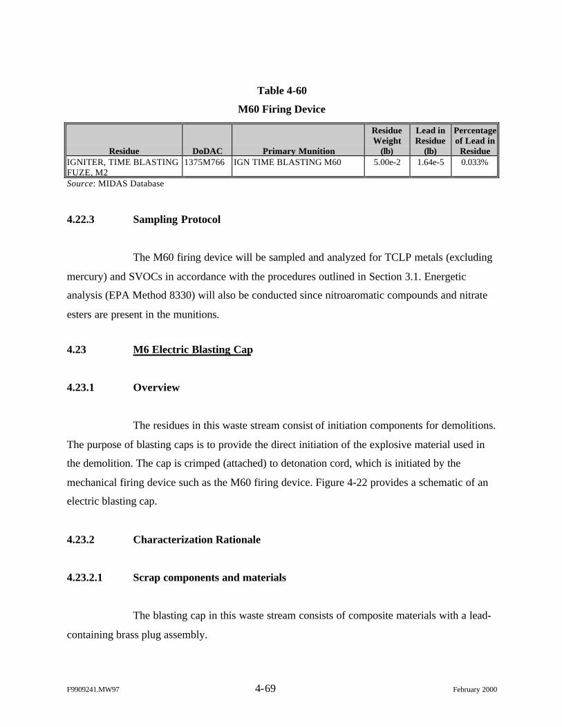
F9909241.MW97 4-69 February 2000
Table 4-60
M60 Firing Device
Residue DoDAC Primary Munition
ResidueWeight
(lb)
Lead inResidue
(lb)
Percentageof Lead in
ResidueIGNITER, TIME BLASTINGFUZE, M2
1375M766 IGN TIME BLASTING M60 5.00e-2 1.64e-5 0.033%
Source: MIDAS Database
4.22.3 Sampling Protocol
The M60 firing device will be sampled and analyzed for TCLP metals (excluding
mercury) and SVOCs in accordance with the procedures outlined in Section 3.1. Energetic
analysis (EPA Method 8330) will also be conducted since nitroaromatic compounds and nitrate
esters are present in the munitions.
4.23 M6 Electric Blasting Cap
4.23.1 Overview
The residues in this waste stream consist of initiation components for demolitions.
The purpose of blasting caps is to provide the direct initiation of the explosive material used in
the demolition. The cap is crimped (attached) to detonation cord, which is initiated by the
mechanical firing device such as the M60 firing device. Figure 4-22 provides a schematic of an
electric blasting cap.
4.23.2 Characterization Rationale
4.23.2.1 Scrap components and materials
The blasting cap in this waste stream consists of composite materials with a lead-
containing brass plug assembly.
F9909241.MW97 4-70 February 2000
Figure 4-22. M6 Electric Blasting Cap
4.23.2.2 Composition of reactive materials associated with the munitions item
The electric blasting cap consists of a main charge and an ignition charge.
Table 4-61 lists the composition of these charges. These charges contain the RCRA TCLP
constituent lead from lead-sodium and lead aside constituents in the amounts shown in
Table 4-61.
Table 4-61
Ignition and Main Charge Composition for M6 Electric Blasting Cap
M6 Electric Blasting CapComponent
Mix ConstituentResidue
Weight (lb)Percentage of
ChargeIgnition Smokeless Powder 1.28e-4 50%Charge Lead-Sodium Dinitro Ortho 6.42e-5 25%
Potassium Chlorate 6.42e-5 25%Main RDX 5.95e-4 98.2%Charge Lead Aside 3.92e-4 1.8%Source: MIDAS Database
F9909241.MW97 4-71 February 2000
4.23.2.3 Maximum theoretical leaching limit evaluation
The weight of the item in this waste stream and the primary hazardous constituent
are listed in Table 4-62. The amount of lead associated with the M6 electric blasting cap is
0.72%, which is well above the TCLP maximum theoretical leaching limit for lead (0.01%).
Therefore, sampling and analysis is required to perform a hazardous waste determination for this
waste stream.
Table 4-62
M6 Electric Blasting Cap
Residue DoDAC Primary Munition
ResidueWeight
(lb)
Lead inResidue
(lb)
Percentageof Lead in
ResidueCAP, BLASTING ELECT M6ASSY
1375M130 CAP BLASTING ELECTRIC M6 7.00e-2 5.05e-4 0.722%
Source: MIDAS Database
4.23.3 Sampling Protocol
The M6 blasting cap will be sampled and analyzed for TCLP metals (excluding
mercury) and SVOCs in accordance with the procedures outlined in Section 3.1. Energetic
analysis (EPA Method 8330) will not be conducted since nitroaromatic compounds and nitrate
esters are not present in the munitions.
4.24 M7 Nonelectric Blasting Cap
4.24.1 Overview
The residues in this waste stream consist of initiation components for demolitions.
The purpose of blasting caps is to provide the direct initiation of the explosive material used in
the demolition. The cap is crimped (attached) to detonation cord, which is initiated by the
mechanical firing device such as the M60 firing device. Figure 4-23 provides a schematic of a
nonelectric blasting cap.

F9909241.MW97 4-72 February 2000
Figure 4-23. M7 Nonelectric Blasting Cap
4.24.2 Characterization Rationale
4.24.2.1 Scrap components and materials
The blasting cap in this waste stream consists of composite materials with a lead-
containing brass cup.
4.24.2.2 Composition of reactive materials associated with the munitions item
The nonelectric blasting cap consists of a main charge. Table 4-63 lists the
composition of the charge. This charge contains the RCRA TCLP constituent lead from lead
styphnate and lead aside constituents in the amounts shown in Table 4-63.
F9909241.MW97 4-73 February 2000
Table 4-63
Main Charge Composition for M7 Nonelectric Blasting Cap
M7 Nonelectric Blasting CapComponent
Mix ConstituentResidue
Weight (lb)Percentageof Charge
Main RDX 2.07e-3 90%Charge Lead Azide 5.28e-4 6%
Lead Styphnate 1.57e-4 4%Source: MIDAS Database
4.24.2.3 Maximum theoretical leaching limit evaluation
The weight of the item in this waste stream and the primary hazardous constituent
are listed in Table 4-64. The amount of lead associated with the M7 nonelectric blasting cap is
11.23%, which is well above the TCLP maximum theoretical leaching limit for lead (0.01%).
Therefore, sampling and analysis is required to perform a hazardous waste determination for this
waste stream.
Table 4-64
M7 Nonelectric Blasting Cap
Residue DoDAC Primary Munition
ResidueWeight
(lb)
Lead inResidue
(lb)
Percentageof Lead in
ResidueCAP, BLASTING NONELEC 1375M131 CAP BLASTING NONELEC M7 4.00e-3 4.49e-4 11.234%Source: MIDAS Database
4.24.3 Sampling Protocol
The M7 blasting cap will be sampled and analyzed for TCLP metals (exclud ing
mercury) and SVOCs in accordance with the procedures outlined in Section 3.1. Energetic
analysis (EPA Method 8330) will not be conducted since nitroaromatic compounds and nitrate
esters are not present in the munitions.
F9909241.MW97 4-74 February 2000
4.25 M5 Steel Demolition Firing Devices
4.25.1 Overview
The residues for this waste stream consist of the expended M5 steel cases used to
initiate demolition charges. The device in this waste stream is composed solely of a percussion
primer. The primer is initiated by the mechanical pull and release of a charging piston. When
released, the piston strikes the primer, which ignites the demolition chain. After use, the firing
device is returned to the issuing office. Figure 4-24 provides a schematic of an M5 firing device.
Figure 4-24. M5 Firing Device
4.25.2 Characterization Rationale
4.25.2.1 Scrap components and materials
The body/case of the M5 firing device is composed of steel and brass
components. The brass components containing lead include the primer percussion body, anvil,
and cup. The steel components may also contain small amounts of cadmium in cadmium
chromate and cadmium plating.
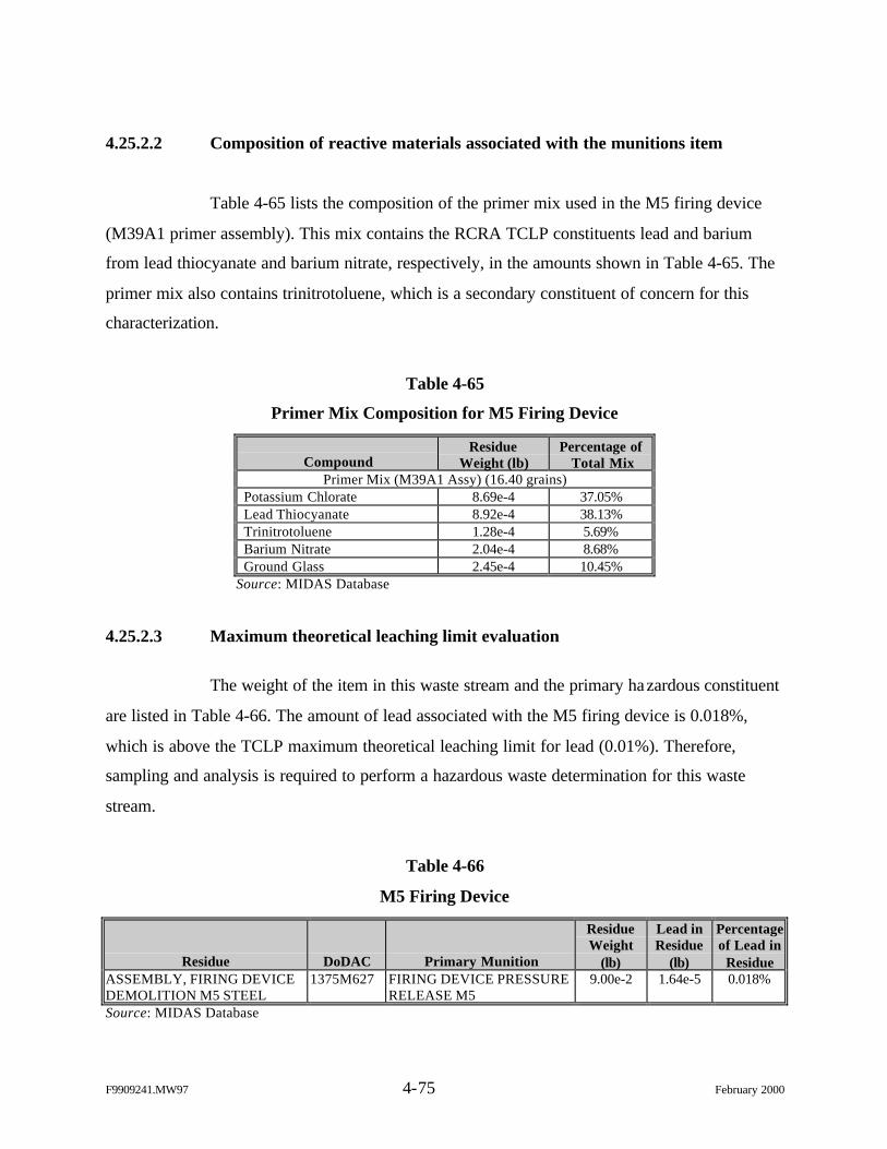
F9909241.MW97 4-75 February 2000
4.25.2.2 Composition of reactive materials associated with the munitions item
Table 4-65 lists the composition of the primer mix used in the M5 firing device
(M39A1 primer assembly). This mix contains the RCRA TCLP constituents lead and barium
from lead thiocyanate and barium nitrate, respectively, in the amounts shown in Table 4-65. The
primer mix also contains trinitrotoluene, which is a secondary constituent of concern for this
characterization.
Table 4-65
Primer Mix Composition for M5 Firing Device
CompoundResidue
Weight (lb)Percentage of
Total MixPrimer Mix (M39A1 Assy) (16.40 grains)
Potassium Chlorate 8.69e-4 37.05%Lead Thiocyanate 8.92e-4 38.13%Trinitrotoluene 1.28e-4 5.69%Barium Nitrate 2.04e-4 8.68%Ground Glass 2.45e-4 10.45%
Source: MIDAS Database
4.25.2.3 Maximum theoretical leaching limit evaluation
The weight of the item in this waste stream and the primary hazardous constituent
are listed in Table 4-66. The amount of lead associated with the M5 firing device is 0.018%,
which is above the TCLP maximum theoretical leaching limit for lead (0.01%). Therefore,
sampling and analysis is required to perform a hazardous waste determination for this waste
stream.
Table 4-66
M5 Firing Device
Residue DoDAC Primary Munition
ResidueWeight
(lb)
Lead inResidue
(lb)
Percentageof Lead in
ResidueASSEMBLY, FIRING DEVICEDEMOLITION M5 STEEL
1375M627 FIRING DEVICE PRESSURERELEASE M5
9.00e-2 1.64e-5 0.018%
Source: MIDAS Database
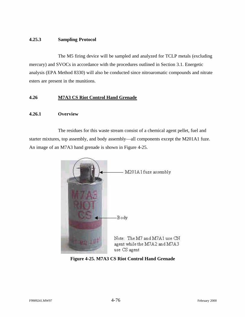
F9909241.MW97 4-76 February 2000
4.25.3 Sampling Protocol
The M5 firing device will be sampled and analyzed for TCLP metals (excluding
mercury) and SVOCs in accordance with the procedures outlined in Section 3.1. Energetic
analysis (EPA Method 8330) will also be conducted since nitroaromatic compounds and nitrate
esters are present in the munitions.
4.26 M7A3 CS Riot Control Hand Grenade
4.26.1 Overview
The residues for this waste stream consist of a chemical agent pellet, fuel and
starter mixtures, top assembly, and body assembly—all components except the M201A1 fuze.
An image of an M7A3 hand grenade is shown in Figure 4-25.
Figure 4-25. M7A3 CS Riot Control Hand Grenade
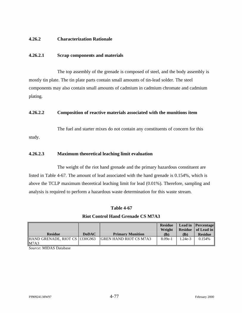
F9909241.MW97 4-77 February 2000
4.26.2 Characterization Rationale
4.26.2.1 Scrap components and materials
The top assembly of the grenade is composed of steel, and the body assembly is
mostly tin plate. The tin plate parts contain small amounts of tin-lead solder. The steel
components may also contain small amounts of cadmium in cadmium chromate and cadmium
plating.
4.26.2.2 Composition of reactive materials associated with the munitions item
The fuel and starter mixes do not contain any constituents of concern for this
study.
4.26.2.3 Maximum theoretical leaching limit evaluation
The weight of the riot hand grenade and the primary hazardous constituent are
listed in Table 4-67. The amount of lead associated with the hand grenade is 0.154%, which is
above the TCLP maximum theoretical leaching limit for lead (0.01%). Therefore, sampling and
analysis is required to perform a hazardous waste determination for this waste stream.
Table 4-67
Riot Control Hand Grenade CS M7A3
Residue DoDAC Primary Munition
ResidueWeight
(lb)
Lead inResidue
(lb)
Percentageof Lead in
ResidueHAND GRENADE, RIOT CSM7A3
1330G963 GREN HAND RIOT CS M7A3 8.09e-1 1.24e-3 0.154%
Source: MIDAS Database
F9909241.MW97 4-78 February 2000
4.26.3 Sampling Protocol
The grenade residues will be sampled and analyzed for TCLP metals (excluding
mercury) and SVOCs in accordance with the procedures outlined in Section 3.1.
4.27 ABC-M5 HC Smoke Pot
4.27.1 Overview
The residues for this waste stream consist of the entire smoke pot, the major
portion of which is White Smoke Mix 2.
4.27.2 Characterization Rationale
4.27.2.1 Scrap components and materials
The 33-lb smoke pot contains 31 lb of smoke mix, with the remaining 2 lb (0.06%
of the total weight) composed of energetic compounds and steel and brass components of
unknown weight. The quantities of lead and possibly cadmium that are present in brass and steel
components are minimal.
4.27.2.2 Composition of reactive materials associated with the munitions item
Table 4-68 lists the composition of the white smoke mixes used in the smoke pot.
These mixes contain HC, a RCRA TCLP constituent.
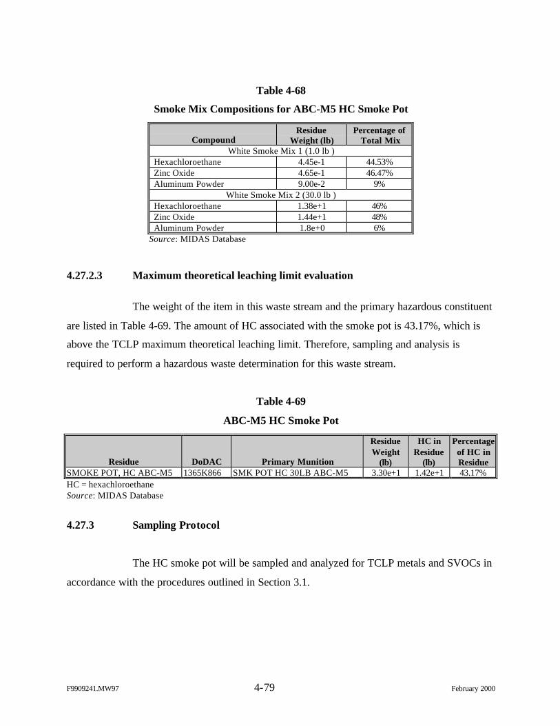
F9909241.MW97 4-79 February 2000
Table 4-68
Smoke Mix Compositions for ABC-M5 HC Smoke Pot
CompoundResidue
Weight (lb)Percentage of
Total MixWhite Smoke Mix 1 (1.0 lb )
Hexachloroethane 4.45e-1 44.53%Zinc Oxide 4.65e-1 46.47%Aluminum Powder 9.00e-2 9%
White Smoke Mix 2 (30.0 lb )Hexachloroethane 1.38e+1 46%Zinc Oxide 1.44e+1 48%Aluminum Powder 1.8e+0 6%
Source: MIDAS Database
4.27.2.3 Maximum theoretical leaching limit evaluation
The weight of the item in this waste stream and the primary hazardous constituent
are listed in Table 4-69. The amount of HC associated with the smoke pot is 43.17%, which is
above the TCLP maximum theoretical leaching limit. Therefore, sampling and analysis is
required to perform a hazardous waste determination for this waste stream.
Table 4-69
ABC-M5 HC Smoke Pot
Residue DoDAC Primary Munition
ResidueWeight
(lb)
HC inResidue
(lb)
Percentageof HC inResidue
SMOKE POT, HC ABC-M5 1365K866 SMK POT HC 30LB ABC-M5 3.30e+1 1.42e+1 43.17%HC = hexachloroethaneSource: MIDAS Database
4.27.3 Sampling Protocol
The HC smoke pot will be sampled and analyzed for TCLP metals and SVOCs in
accordance with the procedures outlined in Section 3.1.
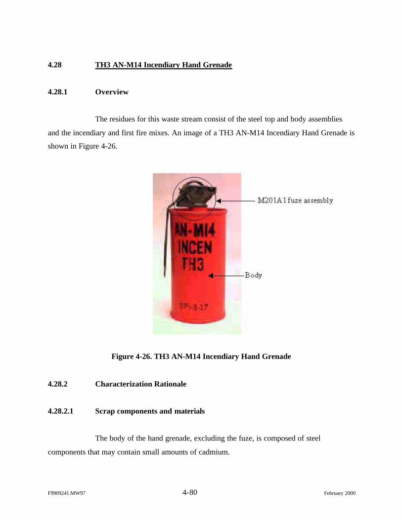
F9909241.MW97 4-80 February 2000
4.28 TH3 AN-M14 Incendiary Hand Grenade
4.28.1 Overview
The residues for this waste stream consist of the steel top and body assemblies
and the incendiary and first fire mixes. An image of a TH3 AN-M14 Incendiary Hand Grenade is
shown in Figure 4-26.
Figure 4-26. TH3 AN-M14 Incendiary Hand Grenade
4.28.2 Characterization Rationale
4.28.2.1 Scrap components and materials
The body of the hand grenade, excluding the fuze, is composed of steel
components that may contain small amounts of cadmium.
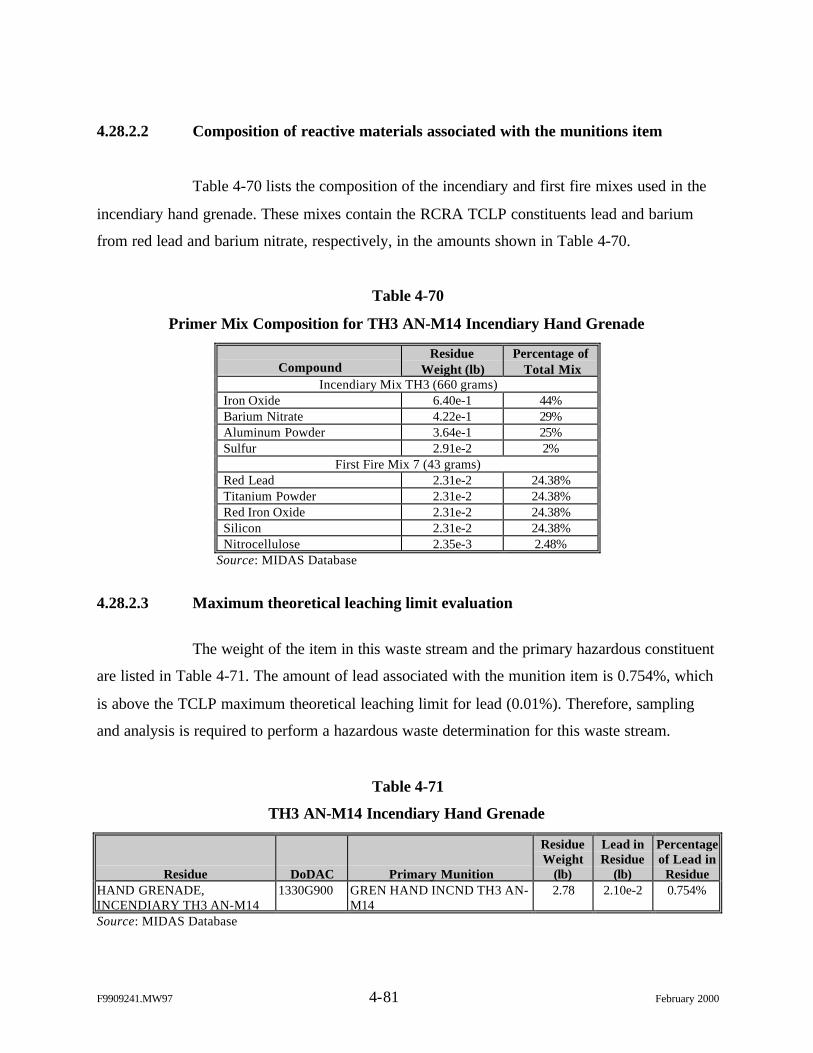
F9909241.MW97 4-81 February 2000
4.28.2.2 Composition of reactive materials associated with the munitions item
Table 4-70 lists the composition of the incendiary and first fire mixes used in the
incendiary hand grenade. These mixes contain the RCRA TCLP constituents lead and barium
from red lead and barium nitrate, respectively, in the amounts shown in Table 4-70.
Table 4-70
Primer Mix Composition for TH3 AN-M14 Incendiary Hand Grenade
CompoundResidue
Weight (lb)Percentage of
Total MixIncendiary Mix TH3 (660 grams)
Iron Oxide 6.40e-1 44%Barium Nitrate 4.22e-1 29%Aluminum Powder 3.64e-1 25%Sulfur 2.91e-2 2%
First Fire Mix 7 (43 grams)Red Lead 2.31e-2 24.38%Titanium Powder 2.31e-2 24.38%Red Iron Oxide 2.31e-2 24.38%Silicon 2.31e-2 24.38%Nitrocellulose 2.35e-3 2.48%
Source: MIDAS Database
4.28.2.3 Maximum theoretical leaching limit evaluation
The weight of the item in this waste stream and the primary hazardous constituent
are listed in Table 4-71. The amount of lead associated with the munition item is 0.754%, which
is above the TCLP maximum theoretical leaching limit for lead (0.01%). Therefore, sampling
and analysis is required to perform a hazardous waste determination for this waste stream.
Table 4-71
TH3 AN-M14 Incendiary Hand Grenade
Residue DoDAC Primary Munition
ResidueWeight
(lb)
Lead inResidue
(lb)
Percentageof Lead in
ResidueHAND GRENADE,INCENDIARY TH3 AN-M14
1330G900 GREN HAND INCND TH3 AN-M14
2.78 2.10e-2 0.754%
Source: MIDAS Database
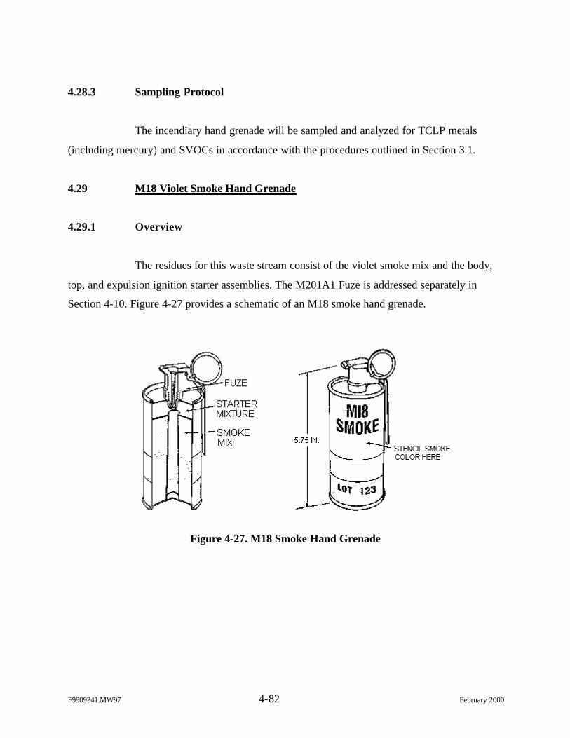
F9909241.MW97 4-82 February 2000
4.28.3 Sampling Protocol
The incendiary hand grenade will be sampled and analyzed for TCLP metals
(including mercury) and SVOCs in accordance with the procedures outlined in Section 3.1.
4.29 M18 Violet Smoke Hand Grenade
4.29.1 Overview
The residues for this waste stream consist of the violet smoke mix and the body,
top, and expulsion ignition starter assemblies. The M201A1 Fuze is addressed separately in
Section 4-10. Figure 4-27 provides a schematic of an M18 smoke hand grenade.
Figure 4-27. M18 Smoke Hand Grenade
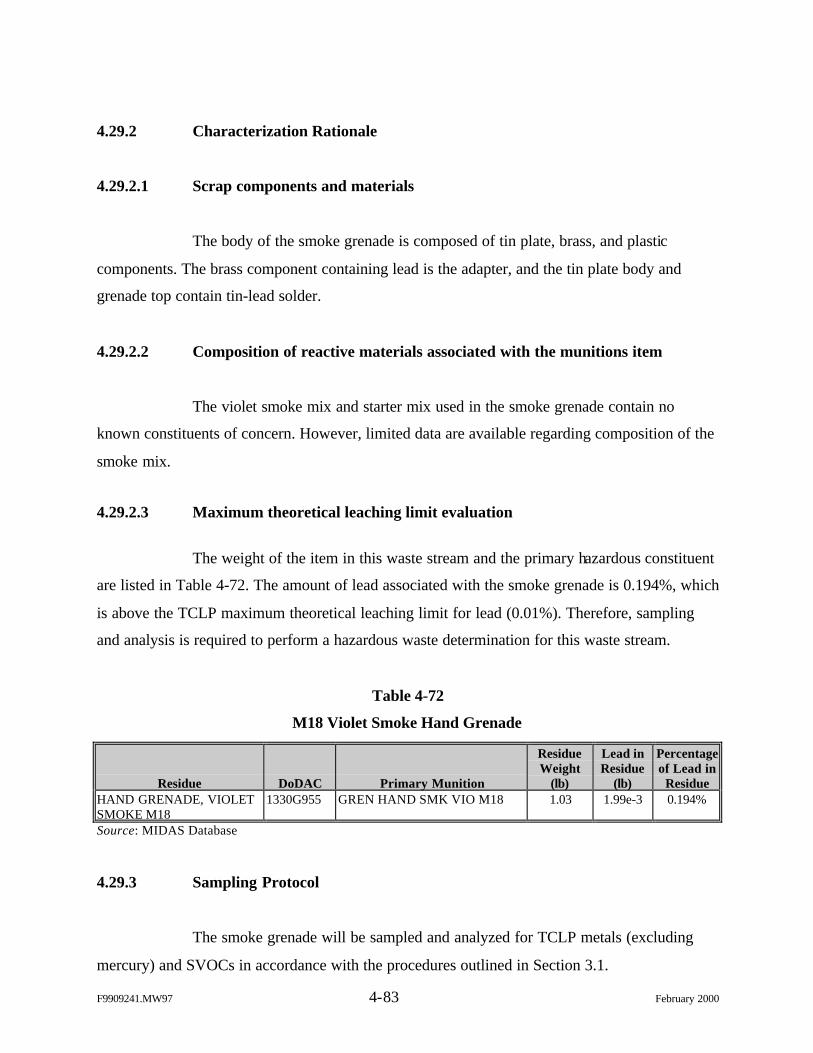
F9909241.MW97 4-83 February 2000
4.29.2 Characterization Rationale
4.29.2.1 Scrap components and materials
The body of the smoke grenade is composed of tin plate, brass, and plastic
components. The brass component containing lead is the adapter, and the tin plate body and
grenade top contain tin-lead solder.
4.29.2.2 Composition of reactive materials associated with the munitions item
The violet smoke mix and starter mix used in the smoke grenade contain no
known constituents of concern. However, limited data are available regarding composition of the
smoke mix.
4.29.2.3 Maximum theoretical leaching limit evaluation
The weight of the item in this waste stream and the primary hazardous constituent
are listed in Table 4-72. The amount of lead associated with the smoke grenade is 0.194%, which
is above the TCLP maximum theoretical leaching limit for lead (0.01%). Therefore, sampling
and analysis is required to perform a hazardous waste determination for this waste stream.
Table 4-72
M18 Violet Smoke Hand Grenade
Residue DoDAC Primary Munition
ResidueWeight
(lb)
Lead inResidue
(lb)
Percentageof Lead in
ResidueHAND GRENADE, VIOLETSMOKE M18
1330G955 GREN HAND SMK VIO M18 1.03 1.99e-3 0.194%
Source: MIDAS Database
4.29.3 Sampling Protocol
The smoke grenade will be sampled and analyzed for TCLP metals (excluding
mercury) and SVOCs in accordance with the procedures outlined in Section 3.1.
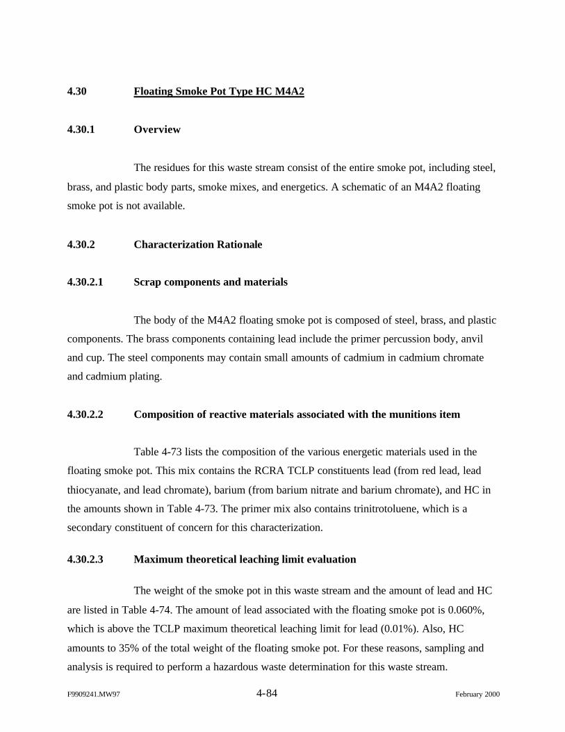
F9909241.MW97 4-84 February 2000
4.30 Floating Smoke Pot Type HC M4A2
4.30.1 Overview
The residues for this waste stream consist of the entire smoke pot, including steel,
brass, and plastic body parts, smoke mixes, and energetics. A schematic of an M4A2 floating
smoke pot is not available.
4.30.2 Characterization Rationale
4.30.2.1 Scrap components and materials
The body of the M4A2 floating smoke pot is composed of steel, brass, and plastic
components. The brass components containing lead include the primer percussion body, anvil
and cup. The steel components may contain small amounts of cadmium in cadmium chromate
and cadmium plating.
4.30.2.2 Composition of reactive materials associated with the munitions item
Table 4-73 lists the composition of the various energetic materials used in the
floating smoke pot. This mix contains the RCRA TCLP constituents lead (from red lead, lead
thiocyanate, and lead chromate), barium (from barium nitrate and barium chromate), and HC in
the amounts shown in Table 4-73. The primer mix also contains trinitrotoluene, which is a
secondary constituent of concern for this characterization.
4.30.2.3 Maximum theoretical leaching limit evaluation
The weight of the smoke pot in this waste stream and the amount of lead and HC
are listed in Table 4-74. The amount of lead associated with the floating smoke pot is 0.060%,
which is above the TCLP maximum theoretical leaching limit for lead (0.01%). Also, HC
amounts to 35% of the total weight of the floating smoke pot. For these reasons, sampling and
analysis is required to perform a hazardous waste determination for this waste stream.
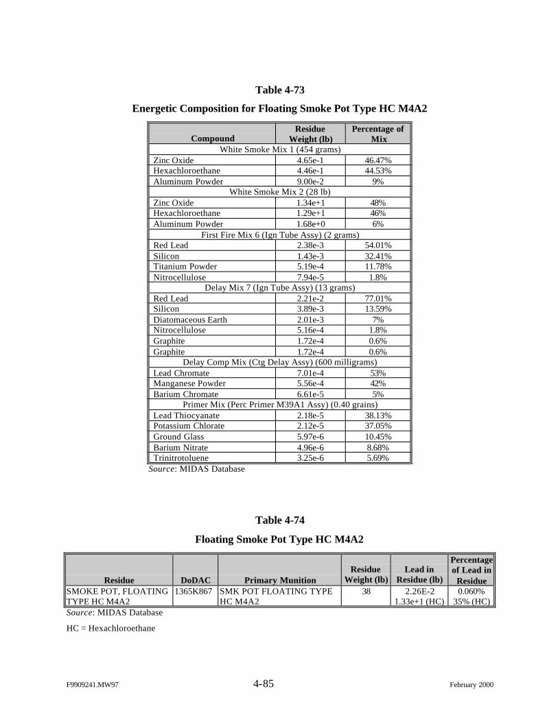
F9909241.MW97 4-85 February 2000
Table 4-73
Energetic Composition for Floating Smoke Pot Type HC M4A2
CompoundResidue
Weight (lb)Percentage of
MixWhite Smoke Mix 1 (454 grams)
Zinc Oxide 4.65e-1 46.47%Hexachloroethane 4.46e-1 44.53%Aluminum Powder 9.00e-2 9%
White Smoke Mix 2 (28 lb)Zinc Oxide 1.34e+1 48%Hexachloroethane 1.29e+1 46%Aluminum Powder 1.68e+0 6%
First Fire Mix 6 (Ign Tube Assy) (2 grams)Red Lead 2.38e-3 54.01%Silicon 1.43e-3 32.41%Titanium Powder 5.19e-4 11.78%Nitrocellulose 7.94e-5 1.8%
Delay Mix 7 (Ign Tube Assy) (13 grams)Red Lead 2.21e-2 77.01%Silicon 3.89e-3 13.59%Diatomaceous Earth 2.01e-3 7%Nitrocellulose 5.16e-4 1.8%Graphite 1.72e-4 0.6%Graphite 1.72e-4 0.6%
Delay Comp Mix (Ctg Delay Assy) (600 milligrams)Lead Chromate 7.01e-4 53%Manganese Powder 5.56e-4 42%Barium Chromate 6.61e-5 5%
Primer Mix (Perc Primer M39A1 Assy) (0.40 grains)Lead Thiocyanate 2.18e-5 38.13%Potassium Chlorate 2.12e-5 37.05%Ground Glass 5.97e-6 10.45%Barium Nitrate 4.96e-6 8.68%Trinitrotoluene 3.25e-6 5.69%
Source: MIDAS Database
Table 4-74
Floating Smoke Pot Type HC M4A2
Residue DoDAC Primary MunitionResidue
Weight (lb)Lead in
Residue (lb)
Percentageof Lead in
ResidueSMOKE POT, FLOATINGTYPE HC M4A2
1365K867 SMK POT FLOATING TYPEHC M4A2
38 2.26E-21.33e+1 (HC)
0.060%35% (HC)
Source: MIDAS Database
HC = Hexachloroethane
F9909241.MW97 4-86 February 2000
4.30.3 Sampling Protocol
The floating smoke pot will be sampled and analyzed for TCLP metals (including
mercury) and SVOCs in accordance with the procedures outlined in Section 3.1. Energetic
analysis (EPA Method 8330) will also be conducted since trinitrotoluene is present in the smoke
pot.
4.31 M11 Nonelectric Blasting Cap (Primary Detonator)
4.31.1 Overview
The nonelectric blasting cap (M11) is used to detonate all standard military
explosives or initiate shock tube blasting caps. The blasting caps are small aluminum tubes filled
with explosives (lead azide and RDX) and then factory-crimped to shock tube (M11 has 30 ft).
The shock tube is a thin plastic tube with a thin layer of explosive (betabiazochloric formalin-
pentoxide (BHT added as preservative) material deposited on its interior surface. A plastic
connector, called a “J hook,” is attached to the sealed end of the shock tube that is seated with a
small cover. The “J hook” allows for easy connection of standard blasting caps to the assembly.
The M11 must be initiated with a blasting cap.
Residues from the detonator and shock tube assemblies consist of the fired
aluminum detonator and the actual shock tube (30 ft length). The “J hook” assembly may or may
not be returned. Figure 4-28 provides a schematic of the M11 nonelectric blasting cap and shock
tube assembly.
Figure 4-28. M11 Nonelectric Blasting Cap
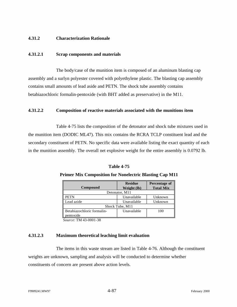
F9909241.MW97 4-87 February 2000
4.31.2 Characterization Rationale
4.31.2.1 Scrap components and materials
The body/case of the munition item is composed of an aluminum blasting cap
assembly and a surlyn polyester covered with polyethylene plastic. The blasting cap assembly
contains small amounts of lead aside and PETN. The shock tube assembly contains
betabiazochloric formalin-pentoxide (with BHT added as preservative) in the M11.
4.31.2.2 Composition of reactive materials associated with the munitions item
Table 4-75 lists the composition of the detonator and shock tube mixtures used in
the munition item (DODIC ML47). This mix contains the RCRA TCLP constituent lead and the
secondary constituent of PETN. No specific data were available listing the exact quantity of each
in the munition assembly. The overall net explosive weight for the entire assembly is 0.0792 lb.
Table 4-75
Primer Mix Composition for Nonelectric Blasting Cap M11
CompoundResidue
Weight (lb)Percentage of
Total MixDetonator, M11
PETN Unavailable UnknownLead azide Unavailable Unknown
Shock Tube, M11Betabiazochloric formalin-pentoxide
Unavailable 100
Source: TM 43-0001-38
4.31.2.3 Maximum theoretical leaching limit evaluation
The items in this waste stream are listed in Table 4-76. Although the constituent
weights are unknown, sampling and analysis will be conducted to determine whether
constituents of concern are present above action levels.
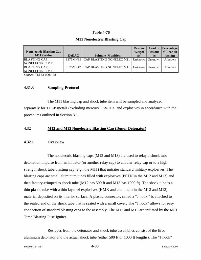
F9909241.MW97 4-88 February 2000
Table 4-76
M11 Nonelectric Blasting Cap
Nonelectric Blasting CapM11Residue DoDAC Primary Munition
ResidueWeight
(lb)
Lead inResidue
(lb)
Percentageof Lead in
ResidueBLASTING CAP,NONELECTRIC M11
1375MN36 CAP BLASTING NONELEC M11 Unknown Unknown Unknown
BLASTING CAP,NONELECTRIC M11
1375ML47 CAP BLASTING NONELEC M11 Unknown Unknown Unknown
Source: TM 43-0001-38
4.31.3 Sampling Protocol
The M11 blasting cap and shock tube item will be sampled and analyzed
separately for TCLP metals (excluding mercury), SVOCs, and explosives in accordance with the
procedures outlined in Section 3.1.
4.32 M12 and M13 Nonelectric Blasting Cap (Donor Detonator)
4.32.1 Overview
The nonelectric blasting caps (M12 and M13) are used to relay a shock tube
detonation impulse from an initiator (or another relay cap) to another relay cap or to a high
strength shock tube blasting cap (e.g., the M11) that initiates standard military explosives. The
blasting caps are small aluminum tubes filled with explosives (PETN in the M12 and M13) and
then factory-crimped to shock tube (M12 has 500 ft and M13 has 1000 ft). The shock tube is a
thin plastic tube with a thin layer of explosives (HMX and aluminum in the M12 and M13)
material deposited on its interior surface. A plastic connector, called a “J hook,” is attached to
the sealed end of the shock tube that is seated with a small cover. The “J hook” allows for easy
connection of standard blasting caps to the assembly. The M12 and M13 are initiated by the M81
Time Blasting Fuse Igniter.
Residues from the detonator and shock tube assemblies consist of the fired
aluminum detonator and the actual shock tube (either 500 ft or 1000 ft lengths). The “J hook”
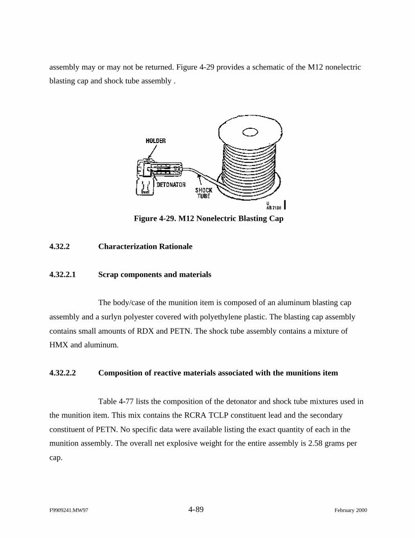
F9909241.MW97 4-89 February 2000
assembly may or may not be returned. Figure 4-29 provides a schematic of the M12 nonelectric
blasting cap and shock tube assembly .
Figure 4-29. M12 Nonelectric Blasting Cap
4.32.2 Characterization Rationale
4.32.2.1 Scrap components and materials
The body/case of the munition item is composed of an aluminum blasting cap
assembly and a surlyn polyester covered with polyethylene plastic. The blasting cap assembly
contains small amounts of RDX and PETN. The shock tube assembly contains a mixture of
HMX and aluminum.
4.32.2.2 Composition of reactive materials associated with the munitions item
Table 4-77 lists the composition of the detonator and shock tube mixtures used in
the munition item. This mix contains the RCRA TCLP constituent lead and the secondary
constituent of PETN. No specific data were available listing the exact quantity of each in the
munition assembly. The overall net explosive weight for the entire assembly is 2.58 grams per
cap.
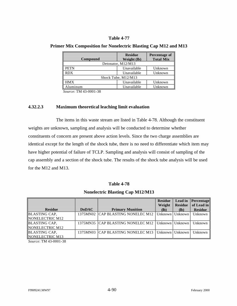
F9909241.MW97 4-90 February 2000
Table 4-77
Primer Mix Composition for Nonelectric Blasting Cap M12 and M13
CompoundResidue
Weight (lb)Percentage of
Total MixDetonator, M12/M13
PETN Unavailable UnknownRDX Unavailable Unknown
Shock Tube, M12/M13HMX Unavailable UnknownAluminum Unavailable Unknown
Source: TM 43-0001-38
4.32.2.3 Maximum theoretical leaching limit evaluation
The items in this waste stream are listed in Table 4-78. Although the constituent
weights are unknown, sampling and analysis will be conducted to determine whether
constituents of concern are present above action levels. Since the two charge assemblies are
identical except for the length of the shock tube, there is no need to differentiate which item may
have higher potential of failure of TCLP. Sampling and analysis will consist of sampling of the
cap assembly and a section of the shock tube. The results of the shock tube analysis will be used
for the M12 and M13.
Table 4-78
Nonelectric Blasting Cap M12/M13
Residue DoDAC Primary Munition
ResidueWeight
(lb)
Lead inResidue
(lb)
Percentageof Lead in
ResidueBLASTING CAP,NONELECTRIC M12
1375MN02 CAP BLASTING NONELEC M12 Unknown Unknown Unknown
BLASTING CAP,NONELECTRIC M12
1375MN35 CAP BLASTING NONELEC M12 Unknown Unknown Unknown
BLASTING CAP,NONELECTRIC M13
1375MN03 CAP BLASTING NONELEC M13 Unknown Unknown Unknown
Source: TM 43-0001-38
F9909241.MW97 4-91 February 2000
4.32.3 Sampling Protocol
The blasting cap and shock tube from any of the three DoDACs will be sampled
and analyzed separately for TCLP metals (excluding mercury), SVOCs, and explosives in
accordance with the procedures outlined in Section 3.1.
4.33 M14 Nonelectric Blasting Cap (Time Fuse)
4.33.1 Overview
Nonelectric blasting cap M14 is used to detonate all standard military explosives
or to initiate shock tube blasting caps approximately 5 minutes after it is ignited by the user. The
M14 is a small aluminum tubes filled with explosives (lead aside, lead styphnate, and PETN) and
then factory-crimped to an approximately 7-1/2 ft length of time blasting fuse. The M14
functions by transmitting an initiating flame (from a blasting fuse igniter or a match) slowly
burning through its length of time blasting fuse into its detonator. The flame coming through the
fuse initiates a small amount of explosives in the detonator. This, in turn, initiates a larger
amount of primary explosives.
Residues from the detonator and time blasting fuze assemblies consist of the fired
aluminum detonator and the actual fuze (7-1/2 ft length). Figure 4-30 provides a schematic of the
M14 nonelectric blasting cap and fuze assembly.
Figure 4-30. M14 Nonelectric Blasting Cap
F9909241.MW97 4-92 February 2000
4.33.2 Characterization Rationale
4.33.2.1 Scrap components and materials
The body/case of the munition item is composed of an aluminum blasting cap
assembly and a surlyn polyester covered with polyethylene plastic. The blasting cap assembly
contains small amounts of lead aside, lead styphnate, and PETN. The time blasting fuze
assembly contains black powder.
4.33.2.2 Composition of reactive materials associated with the munitions item
Table 4-79 lists the composition of the detonator and fuze mixtures used in the
munition item. This mix contains the RCRA TCLP constituent lead and the secondary
constituent of PETN. No specific data were available listing the exact quantity of each in the
munition assembly. The overall net explosive weight for the entire assembly is 0.0792 lb. There
are no constituents of concern associated with the time blasting fuze.
Table 4-79
Primer Mix Composition for Nonelectric Blasting Cap M14
CompoundResidue
Weight (lb)Percentage of
Total MixDetonator, M14
PETN Unavailable UnknownLead Styphnate Unavailable UnknownLead aside Unavailable Unknown
Time Blasting Fuze, M14Black Powder Unavailable 100
Source: TM 43-0001-38
4.33.2.3 Maximum theoretical leaching limit evaluation
The items in this waste stream are listed in Table 4-80. Although the constituent
weights are unknown, sampling and analysis will be conducted to determine whether
constituents of concern are present above action levels..
F9909241.MW97 4-93 February 2000
Table 4-80
Nonelectric Blasting Cap M14
Residue DoDAC Primary Munition
ResidueWeight
(lb)
Lead inResidue
(lb)
Percentageof Lead in
ResidueBLASTING CAP,NONELECTRIC DELAYM14
MN06 CAP BLASTING NONELECDELAY M14
Unknown Unknown Unknown
BLASTING CAP,NONELECTRIC DELAYM14
MN37 CAP BLASTING NONELECDELAY M14
Unknown Unknown Unknown
Source: TM 43-0001-38
4.33.3 Sampling Protocol
The M14 blasting cap will be sampled and analyzed for TCLP metals (excluding
mercury), SVOCs, and explosives in accordance with the procedures outlined in Section 3.1.
4.34 M15 Nonelectric Delay Blasting Cap
4.34.1 Overview
The M15 nonelectric blasting cap is used to provide a delay element in a shock
tube blasting cap priming system to obtain staged detonations such as those used in quarrying
operations. Normally, several M15s are used in tandem to obtain a multi-stage detonation with a
slight delay between each stage to allow the outer layer of rock to start moving before the next
layer’s detonation occurs.
The M15 consists of two small aluminum tubes (detonators) filled with explosives
and factory-crimped to each end of a 70-ft length of shock tube. Shock tube is a thin
polyethylene tube with a layer of explosives deposited on its interior surface. The detonators are
different sizes and contain different delay elements. The shorter piece initiates additional
detonators, while the longer piece initiates the explosives. A “J hook” is used to attach the
multiple shock tube assemblies. A blasting cap must initiate the M15. Figure 4-31 illustrates the
M15 assembly.
F9909241.MW97 4-94 February 2000
Figure 4-31. M15 Nonelectric Delay Blasting Cap
4.34.2 Characterization Rationale
4.34.2.1 Scrap components and materials
The body/case of the munition item is composed of an aluminum blasting cap
assembly and a surlyn polyester covered with polyethylene plastic. The blasting cap assembly
contains small amounts of lead aside and PETN. The shock tube assembly contains HMX and
aluminum.
4.34.2.2 Composition of reactive materials associated with the munitions item
Table 4-81 lists the composition of the detonator and shock tube mixtures used in
the munition item. This mix contains the RCRA TCLP constituent lead and the secondary
constituents of PETN and HMX. No specific data were available listing the exact quantity of
each in the munition assembly. The overall net explosive weight for the entire assembly is 1.63
grams.
Table 4-81
Primer Mix Composition for Nonelectric Blasting Cap M15
CompoundResidue
Weight (lb)Percentage of
Total MixDetonator, M15
PETN Unavailable UnknownLead aside Unavailable Unknown
Shock Tube, M15HMX Unavailable UnknownAluminum Unavailable Unknown
Source: TM 43-0001-38
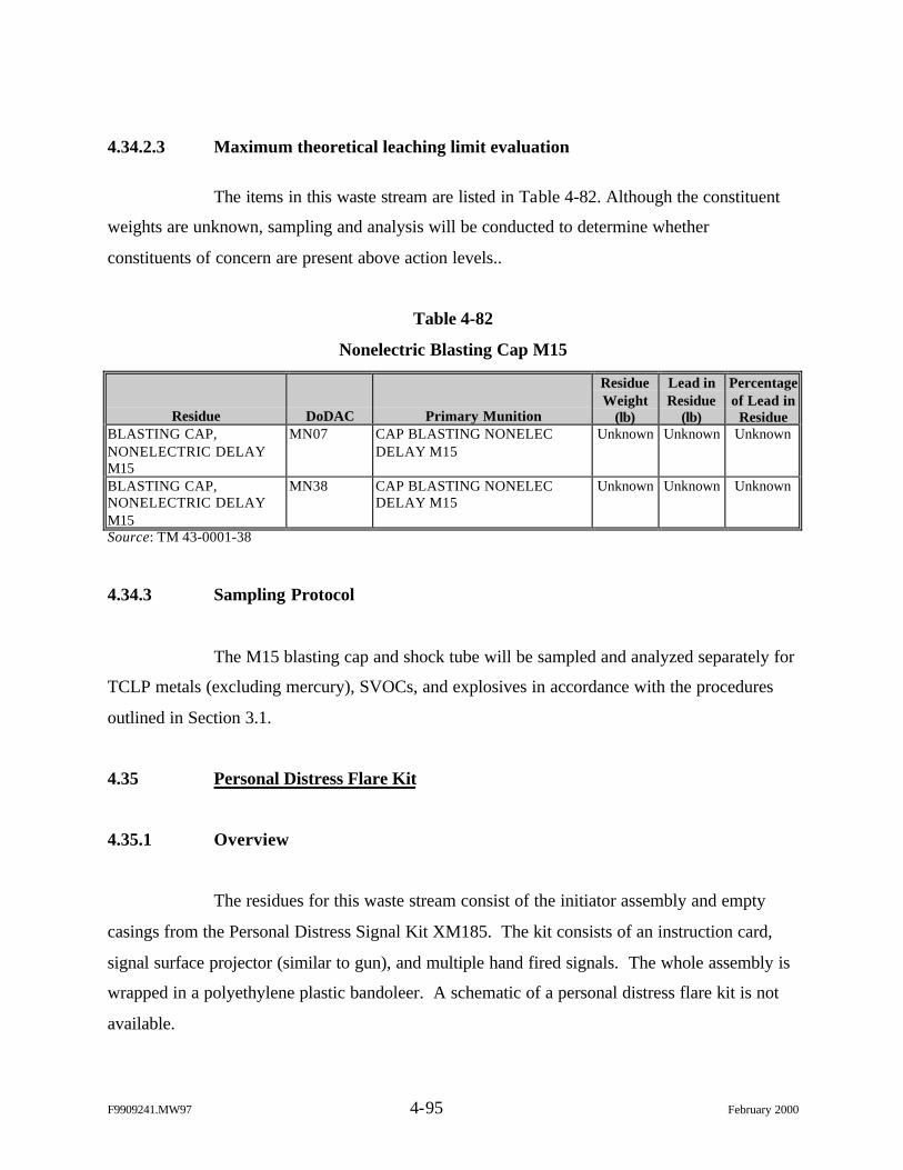
F9909241.MW97 4-95 February 2000
4.34.2.3 Maximum theoretical leaching limit evaluation
The items in this waste stream are listed in Table 4-82. Although the constituent
weights are unknown, sampling and analysis will be conducted to determine whether
constituents of concern are present above action levels..
Table 4-82
Nonelectric Blasting Cap M15
Residue DoDAC Primary Munition
ResidueWeight
(lb)
Lead inResidue
(lb)
Percentageof Lead in
ResidueBLASTING CAP,NONELECTRIC DELAYM15
MN07 CAP BLASTING NONELECDELAY M15
Unknown Unknown Unknown
BLASTING CAP,NONELECTRIC DELAYM15
MN38 CAP BLASTING NONELECDELAY M15
Unknown Unknown Unknown
Source: TM 43-0001-38
4.34.3 Sampling Protocol
The M15 blasting cap and shock tube will be sampled and analyzed separately for
TCLP metals (excluding mercury), SVOCs, and explosives in accordance with the procedures
outlined in Section 3.1.
4.35 Personal Distress Flare Kit
4.35.1 Overview
The residues for this waste stream consist of the initiator assembly and empty
casings from the Personal Distress Signal Kit XM185. The kit consists of an instruction card,
signal surface projector (similar to gun), and multiple hand fired signals. The whole assembly is
wrapped in a polyethylene plastic bandoleer. A schematic of a personal distress flare kit is not
available.
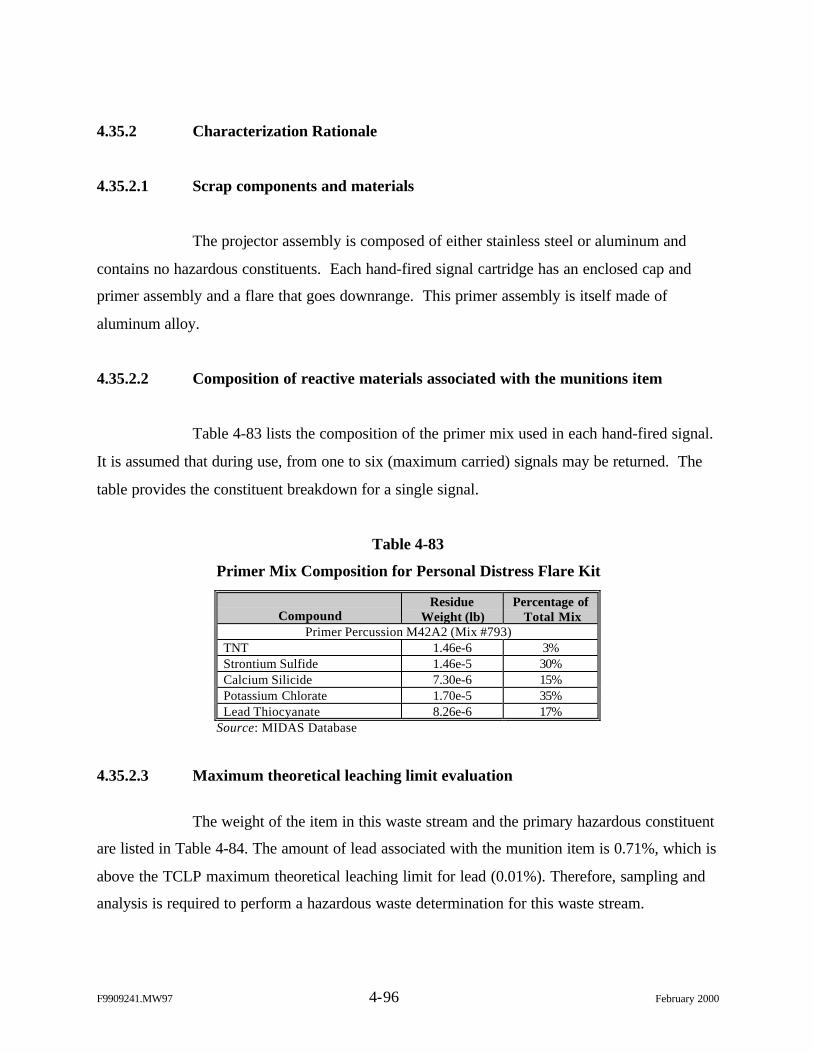
F9909241.MW97 4-96 February 2000
4.35.2 Characterization Rationale
4.35.2.1 Scrap components and materials
The projector assembly is composed of either stainless steel or aluminum and
contains no hazardous constituents. Each hand-fired signal cartridge has an enclosed cap and
primer assembly and a flare that goes downrange. This primer assembly is itself made of
aluminum alloy.
4.35.2.2 Composition of reactive materials associated with the munitions item
Table 4-83 lists the composition of the primer mix used in each hand-fired signal.
It is assumed that during use, from one to six (maximum carried) signals may be returned. The
table provides the constituent breakdown for a single signal.
Table 4-83
Primer Mix Composition for Personal Distress Flare Kit
CompoundResidue
Weight (lb)Percentage of
Total MixPrimer Percussion M42A2 (Mix #793)
TNT 1.46e-6 3%Strontium Sulfide 1.46e-5 30%Calcium Silicide 7.30e-6 15%Potassium Chlorate 1.70e-5 35%Lead Thiocyanate 8.26e-6 17%
Source: MIDAS Database
4.35.2.3 Maximum theoretical leaching limit evaluation
The weight of the item in this waste stream and the primary hazardous constituent
are listed in Table 4-84. The amount of lead associated with the munition item is 0.71%, which is
above the TCLP maximum theoretical leaching limit for lead (0.01%). Therefore, sampling and
analysis is required to perform a hazardous waste determination for this waste stream.
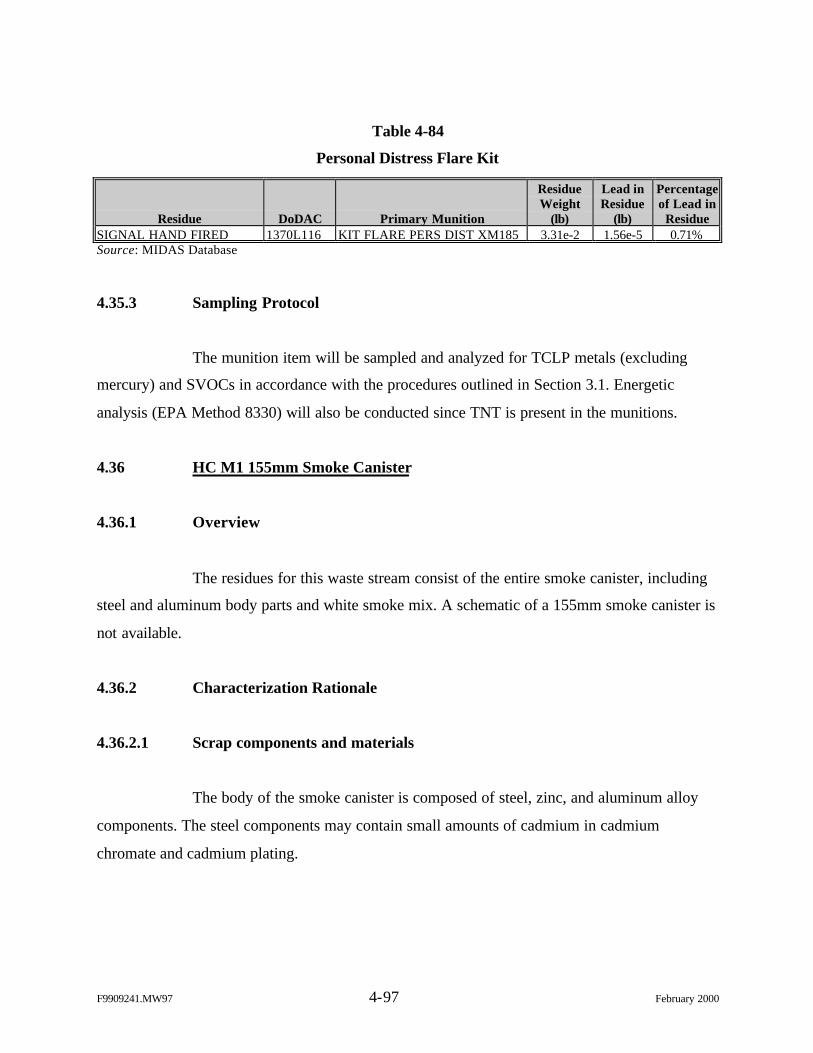
F9909241.MW97 4-97 February 2000
Table 4-84
Personal Distress Flare Kit
Residue DoDAC Primary Munition
ResidueWeight
(lb)
Lead inResidue
(lb)
Percentageof Lead in
ResidueSIGNAL HAND FIRED 1370L116 KIT FLARE PERS DIST XM185 3.31e-2 1.56e-5 0.71%Source: MIDAS Database
4.35.3 Sampling Protocol
The munition item will be sampled and analyzed for TCLP metals (excluding
mercury) and SVOCs in accordance with the procedures outlined in Section 3.1. Energetic
analysis (EPA Method 8330) will also be conducted since TNT is present in the munitions.
4.36 HC M1 155mm Smoke Canister
4.36.1 Overview
The residues for this waste stream consist of the entire smoke canister, including
steel and aluminum body parts and white smoke mix. A schematic of a 155mm smoke canister is
not available.
4.36.2 Characterization Rationale
4.36.2.1 Scrap components and materials
The body of the smoke canister is composed of steel, zinc, and aluminum alloy
components. The steel components may contain small amounts of cadmium in cadmium
chromate and cadmium plating.
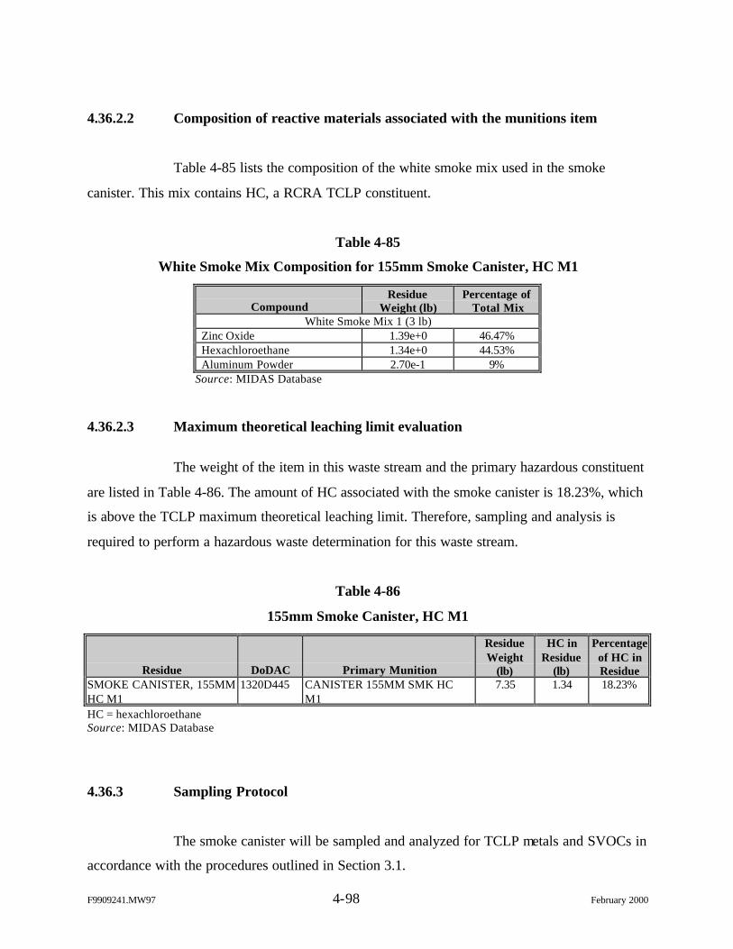
F9909241.MW97 4-98 February 2000
4.36.2.2 Composition of reactive materials associated with the munitions item
Table 4-85 lists the composition of the white smoke mix used in the smoke
canister. This mix contains HC, a RCRA TCLP constituent.
Table 4-85
White Smoke Mix Composition for 155mm Smoke Canister, HC M1
CompoundResidue
Weight (lb)Percentage of
Total MixWhite Smoke Mix 1 (3 lb)
Zinc Oxide 1.39e+0 46.47%Hexachloroethane 1.34e+0 44.53%Aluminum Powder 2.70e-1 9%
Source: MIDAS Database
4.36.2.3 Maximum theoretical leaching limit evaluation
The weight of the item in this waste stream and the primary hazardous constituent
are listed in Table 4-86. The amount of HC associated with the smoke canister is 18.23%, which
is above the TCLP maximum theoretical leaching limit. Therefore, sampling and analysis is
required to perform a hazardous waste determination for this waste stream.
Table 4-86
155mm Smoke Canister, HC M1
Residue DoDAC Primary Munition
ResidueWeight
(lb)
HC inResidue
(lb)
Percentageof HC inResidue
SMOKE CANISTER, 155MMHC M1
1320D445 CANISTER 155MM SMK HCM1
7.35 1.34 18.23%
HC = hexachloroethaneSource: MIDAS Database
4.36.3 Sampling Protocol
The smoke canister will be sampled and analyzed for TCLP metals and SVOCs in
accordance with the procedures outlined in Section 3.1.
F9909241.MW97 4-99 February 2000
4.37 Fired 10 Gauge Shotgun Cartridge Cases
4.37.1 Overview
This residue is the expended 10 gauge cartridge case. The small arms ammunition
is composed of a black powder propellant initiated by a percussion primer. The blank is used for
reveille and retreat salutes and is fired in the 3-in. gun, 75mm gun, 75mm howitzer, and 105mm
howitzer. The cartridge is similar to standard shotgun rounds but contains no lead shot. It has a
paper case with the forward closing disc marked "BLANK." The cartridge produces a sound
when initiated and is inserted either in a prepared cartridge case or in a breech block of the
weapon being used. Figure 4-32 provides a schematic of a typical 10 gauge shotgun cartridge.
Figure 4-32. 10 Gauge Shotgun Cartridge
4.37.2 Characterization Rationale
4.37.2.1 Scrap components and materials
According to the DoD references, the cartridge cases for these munitions are
composed of paper with a brass cartridge head that acts as the primer assembly. However,
discussions with both Olin-Winchester and Remington (government ammunition manufacturers)
indicate that the paper-casing munitions were all replaced with plastic-only casings within the
F9909241.MW97 4-100 February 2000
past 5 years. There are no suspected RCRA TCLP constituents in the cartridge case materials;
the casing is composed of polyethylene with a copper and zinc cartridge head.
4.37.2.2 Composition of reactive materials associated with the munitions item
The primer mix used in the cartridge contains lead from lead styphnate and
barium from barium nitrate in the amounts shown in Table 4-87. Constituent data for this
munition are not available in MIDAS. Therefore, constituent information was obtained from
Olin-Winchester on the typical composition of a 10 gauge shotgun blank round.
Table 4-87
Primer Mix for 10 Gauge Shotgun Cartridges
CompoundResidue
Weight (lb)Percentage ofPrimer Mix
Primer MixLead Styphnate (5.6 to 10%) Unknown UnknownIron (50 to 56%) Unknown UnknownCopper (2.8 to 20%) Unknown UnknownZinc (5.6 to 10%) Unknown UnknownBarium Nitrate (5.6 to 10%) Unknown Unknown
Source: Olin-Winchester MSDS
The propellant for the 10 gauge shotgun blank is black powder. Therefore, no
hazardous constituents of concern are present in the propellant to warrant additional
investigation, sampling, or analysis.
4.37.2.3 Maximum theoretical leaching limit evaluation
The item in this waste stream is listed in Table 4-88. Note that data on material
composition are only available from a Material Safety Data Sheet provided by Olin-Winchester,
a small arms ammunition manufacturer. Therefore, the exact percentage of lead in the primer is
unavailable. Sampling and analysis is recommended since all remaining small arms ammunition
that is larger and smaller in caliber are being sampled and these residues all contain lead
concentrations in the primer greater than the 0.01% theoretical leaching limit for TCLP.
F9909241.MW97 4-101 February 2000
Table 4-88
10 Gauge Shotgun Cartridge Cases
Residue DoDAC Primary MunitionResidue
Weight (lb)Lead in
Residue (lb)
Percentage ofLead inResidue
CASE, CTG, FIRED, BRASSAND PAPER/PLASTIC
1305A010 CTG 10 GA SHOTGUNBUCKSHOT BLANK
Unknown Unknown Unknown
Source: MIDAS Database
4.37.3 Sampling Protocol
The samples will be analyzed for TCLP metals (excluding mercury) and SVOCs
in accordance with the procedures outlined in Section 3.1. Energetic analysis (EPA Method
8330) will not be conducted since no explosive constituents are present in the munition.
4.38 M81 Firing Device
4.38.1 Overview
The M81 igniter is used to ignite the time blasting fuse or to initiate the shock
tube of the new shock tube non-electric blasting caps. The M81 is a small plastic tube with a
pull ring on a thin rod projecting from one end, a safety (cotter) pin that goes laterally through
the tube and a screw cap that secures a holding mechanism for the fuse or shock tube on the
other end.
The M81 is manually initiated by the operator. The cut end of either the time
blasting fuse or shock tube is inserted in the hole where the plug is removed. The cotter pin is
then removed and the operator pulls the pull ring. This action pulls the firing pin back; when
released, the firing pin is forced into the M42 primer (located within the assembly), which fires
with a flame and an explosive shock igniting the fuse or initiating the shock tube. Figure 4-33
shows the M81 firing device
F9909241.MW97 4-102 February 2000
Figure 4-33. M81 Firing Device
4.38.2 Characterization Rationale
4.38.2.1 Scrap components and materials
The M81 firing device is composed of a plastic casing and steel metal
components for the cotter pin, firing pin, pull ring, and spring assemblies. Once the M81 firing
device is no longer useable, the entire assembly is considered scrap.
4.38.2.2 Composition of reactive materials associated with the munitions item
The primer for the M81 firing device is the M42 primer assembly. Table 4-89
lists the properties of the primer mix. This mix contains the RCRA TCLP constituent lead from
the lead thiocyanate in the amounts shown in Table 4-89. The primer mix also contains TNT,
which is a secondary constituent of concern for this characterization.
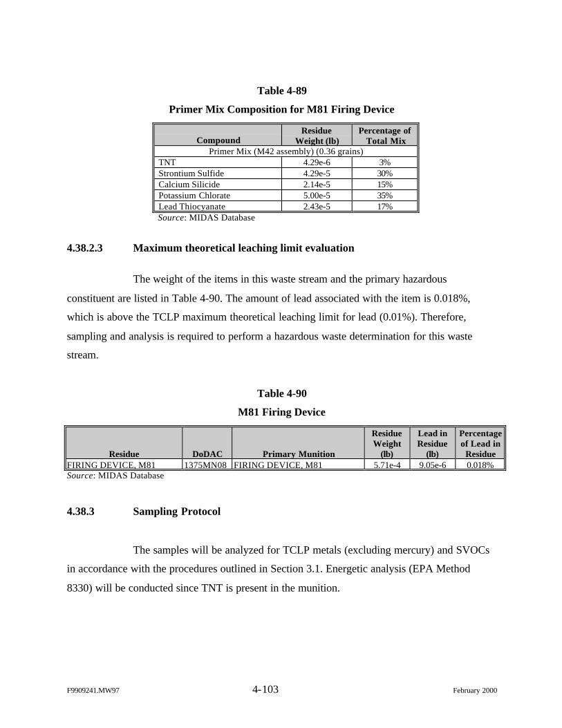
F9909241.MW97 4-103 February 2000
Table 4-89
Primer Mix Composition for M81 Firing Device
CompoundResidue
Weight (lb)Percentage of
Total MixPrimer Mix (M42 assembly) (0.36 grains)
TNT 4.29e-6 3%Strontium Sulfide 4.29e-5 30%Calcium Silicide 2.14e-5 15%Potassium Chlorate 5.00e-5 35%Lead Thiocyanate 2.43e-5 17%Source: MIDAS Database
4.38.2.3 Maximum theoretical leaching limit evaluation
The weight of the items in this waste stream and the primary hazardous
constituent are listed in Table 4-90. The amount of lead associated with the item is 0.018%,
which is above the TCLP maximum theoretical leaching limit for lead (0.01%). Therefore,
sampling and analysis is required to perform a hazardous waste determination for this waste
stream.
Table 4-90
M81 Firing Device
Residue DoDAC Primary Munition
ResidueWeight
(lb)
Lead inResidue
(lb)
Percentageof Lead in
ResidueFIRING DEVICE, M81 1375MN08 FIRING DEVICE, M81 5.71e-4 9.05e-6 0.018%Source: MIDAS Database
4.38.3 Sampling Protocol
The samples will be analyzed for TCLP metals (excluding mercury) and SVOCs
in accordance with the procedures outlined in Section 3.1. Energetic analysis (EPA Method
8330) will be conducted since TNT is present in the munition.
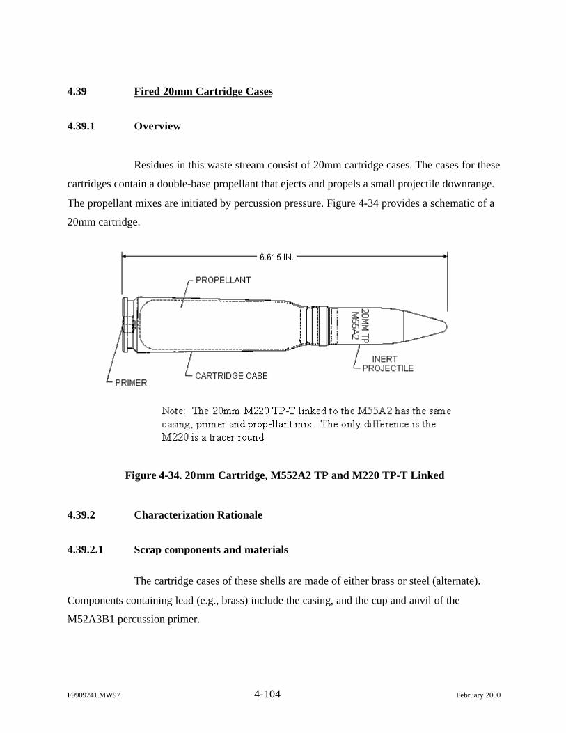
F9909241.MW97 4-104 February 2000
4.39 Fired 20mm Cartridge Cases
4.39.1 Overview
Residues in this waste stream consist of 20mm cartridge cases. The cases for these
cartridges contain a double-base propellant that ejects and propels a small projectile downrange.
The propellant mixes are initiated by percussion pressure. Figure 4-34 provides a schematic of a
20mm cartridge.
Figure 4-34. 20mm Cartridge, M552A2 TP and M220 TP-T Linked
4.39.2 Characterization Rationale
4.39.2.1 Scrap components and materials
The cartridge cases of these shells are made of either brass or steel (alternate).
Components containing lead (e.g., brass) include the casing, and the cup and anvil of the
M52A3B1 percussion primer.
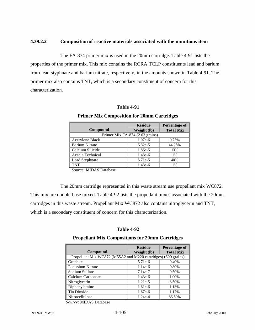
F9909241.MW97 4-105 February 2000
4.39.2.2 Composition of reactive materials associated with the munitions item
The FA-874 primer mix is used in the 20mm cartridge. Table 4-91 lists the
properties of the primer mix. This mix contains the RCRA TCLP constituents lead and barium
from lead styphnate and barium nitrate, respectively, in the amounts shown in Table 4-91. The
primer mix also contains TNT, which is a secondary constituent of concern for this
characterization.
Table 4-91
Primer Mix Composition for 20mm Cartridges
CompoundResidue
Weight (lb)Percentage of
Total MixPrimer Mix FA-874 (2.63 grains)
Acetylene Black 1.07e-6 0.75%Barium Nitrate 6.32e-5 44.25%Calcium Silicide 1.86e-5 13%Acacia Technical 1.43e-6 1%Lead Styphnate 5.71e-5 40%TNT 1.43e-6 1%Source: MIDAS Database
The 20mm cartridge represented in this waste stream use propellant mix WC872.
This mix are double-base mixed. Table 4-92 lists the propellant mixes associated with the 20mm
cartridges in this waste stream. Propellant Mix WC872 also contains nitroglycerin and TNT,
which is a secondary constituent of concern for this characterization.
Table 4-92
Propellant Mix Compositions for 20mm Cartridges
CompoundResidue
Weight (lb)Percentage of
Total MixPropellant Mix WC872 (M55A2 and M220 cartridges) (600 grains)
Graphite 5.71e-6 0.40%Potassium Nitrate 1.14e-6 0.80%Sodium Sulfate 7.14e-7 0.50%Calcium Carbonate 1.43e-6 1.00%Nitroglycerin 1.21e-5 8.50%Diphenylamine 1.61e-6 1.13%Tin Dioxide 1.67e-6 1.17%Nitrocellulose 1.24e-4 86.50%
Source: MIDAS Database
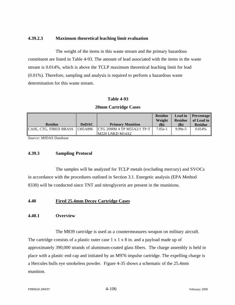
F9909241.MW97 4-106 February 2000
4.39.2.3 Maximum theoretical leaching limit evaluation
The weight of the items in this waste stream and the primary hazardous
constituent are listed in Table 4-93. The amount of lead associated with the items in the waste
stream is 0.014%, which is above the TCLP maximum theoretical leaching limit for lead
(0.01%). Therefore, sampling and analysis is required to perform a hazardous waste
determination for this waste stream.
Table 4-93
20mm Cartridge Cases
Residue DoDAC Primary Munition
ResidueWeight
(lb)
Lead inResidue
(lb)
Percentageof Lead in
ResidueCASE, CTG, FIRED BRASS 1305A896 CTG 20MM 4 TP M55A2/1 TP-T
M220 LNKD M14A27.05e-1 9.99e-5 0.014%
Source: MIDAS Database
4.39.3 Sampling Protocol
The samples will be analyzed for TCLP metals (excluding mercury) and SVOCs
in accordance with the procedures outlined in Section 3.1. Energetic analysis (EPA Method
8330) will be conducted since TNT and nitroglycerin are present in the munitions.
4.40 Fired 25.4mm Decoy Cartridge Cases
4.40.1 Overview
The M839 cartridge is used as a countermeasures weapon on military aircraft.
The cartridge consists of a plastic outer case 1 x 1 x 8 in. and a payload made up of
approximately 390,000 strands of aluminum-coated glass fibers. The charge assembly is held in
place with a plastic end cap and initiated by an M976 impulse cartridge. The expelling charge is
a Hercules bulls eye smokeless powder. Figure 4-35 shows a schematic of the 25.4mm
munition.
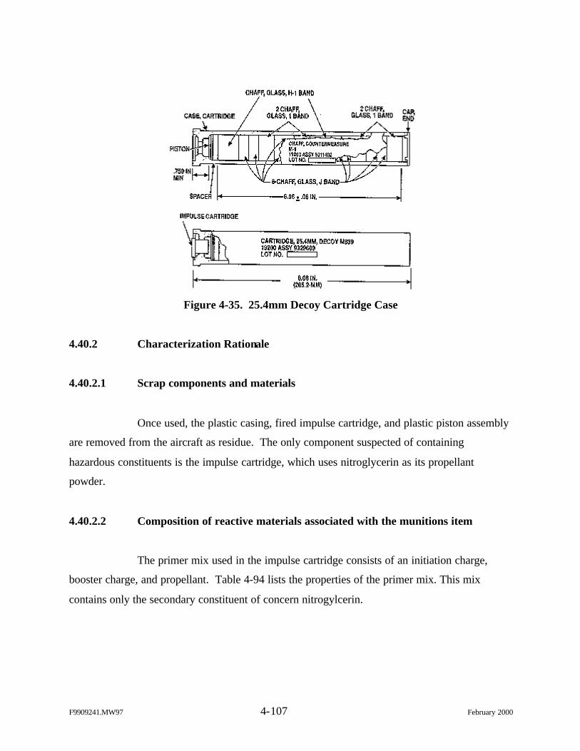
F9909241.MW97 4-107 February 2000
Figure 4-35. 25.4mm Decoy Cartridge Case
4.40.2 Characterization Rationale
4.40.2.1 Scrap components and materials
Once used, the plastic casing, fired impulse cartridge, and plastic piston assembly
are removed from the aircraft as residue. The only component suspected of containing
hazardous constituents is the impulse cartridge, which uses nitroglycerin as its propellant
powder.
4.40.2.2 Composition of reactive materials associated with the munitions item
The primer mix used in the impulse cartridge consists of an initiation charge,
booster charge, and propellant. Table 4-94 lists the properties of the primer mix. This mix
contains only the secondary constituent of concern nitrogylcerin.
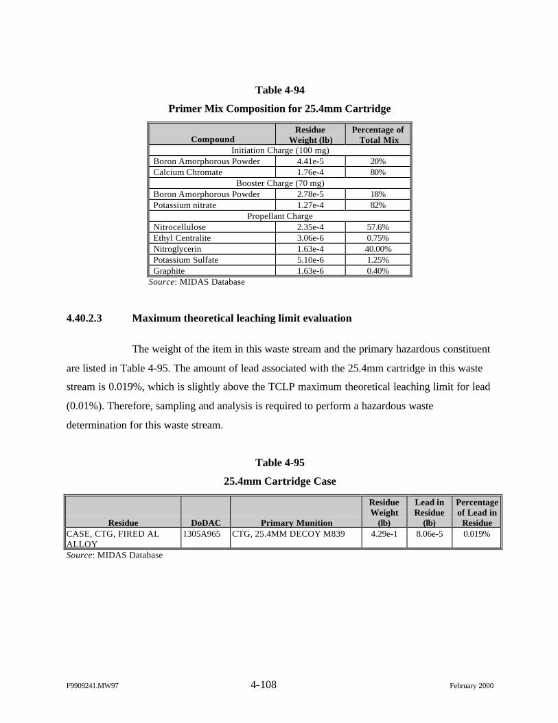
F9909241.MW97 4-108 February 2000
Table 4-94
Primer Mix Composition for 25.4mm Cartridge
CompoundResidue
Weight (lb)Percentage of
Total MixInitiation Charge (100 mg)
Boron Amorphorous Powder 4.41e-5 20%Calcium Chromate 1.76e-4 80%
Booster Charge (70 mg)Boron Amorphorous Powder 2.78e-5 18%Potassium nitrate 1.27e-4 82%
Propellant ChargeNitrocellulose 2.35e-4 57.6%Ethyl Centralite 3.06e-6 0.75%Nitroglycerin 1.63e-4 40.00%Potassium Sulfate 5.10e-6 1.25%Graphite 1.63e-6 0.40%
Source: MIDAS Database
4.40.2.3 Maximum theoretical leaching limit evaluation
The weight of the item in this waste stream and the primary hazardous constituent
are listed in Table 4-95. The amount of lead associated with the 25.4mm cartridge in this waste
stream is 0.019%, which is slightly above the TCLP maximum theoretical leaching limit for lead
(0.01%). Therefore, sampling and analysis is required to perform a hazardous waste
determination for this waste stream.
Table 4-95
25.4mm Cartridge Case
Residue DoDAC Primary Munition
ResidueWeight
(lb)
Lead inResidue
(lb)
Percentageof Lead in
ResidueCASE, CTG, FIRED ALALLOY
1305A965 CTG, 25.4MM DECOY M839 4.29e-1 8.06e-5 0.019%
Source: MIDAS Database
F9909241.MW97 4-109 February 2000
4.40.3 Sampling Protocol
The 25.4mm cartridge case in this waste stream, DoDAC 1305A965, will be
sampled and analyzed for SVOCs in accordance with the procedures outlined in Section 3.1.
Energetic analysis (EPA Method 8330) will also be conducted since nitroglycerin is present in
the munitions item. Testing for TCLP metals will not occur since there are no known metals of
concern (e.g., lead) in the munition residue.

This page intentionally left blank.
F9909241.MW97 5-1 February 2000
5.0 DATA INTERPRETATION AND REPORTING
5.1 Data Reduction, Validation, and Reporting
5.1.1 Data Reduction
Data reduction will be completed by the analytical and QA laboratories in
accordance with their published QA plans.
5.1.2 Calculation of Data Quality Indicators
5.1.2.1 Precision
For chemical analysis of environmental samples for this project, precision will be
determined from duplicate laboratory sample analyses; therefore, precision will be expressed as
RPD. Every batch of samples analyzed will include matrix spikes and/or matrix spike duplicates to
evaluate precision. Precision determined by RPD will be calculated as follows.
RPD = {[absolute value of (X1 - X2)]/[(X1 + X2)/2]} x 100%
Where:
X1 = primary sample result,X2 = duplicate sample result.
5.1.2.2 Accuracy
Accuracy will be determined from spiked samples (laboratory control and matrix
spike samples) for this project and will be expressed as percent recovery (%R). Accuracy
determined by percent recovery is calculated as follows:
%R = [(XS - XU)/K] x 100%
F9909241.MW97 5-2 February 2000
Where:
XS = measured value of the spiked sample,XU = measured value of the unspiked sample,K = known amount of the spike in the sample.
5.1.2.3 Completeness
Completeness, expressed as percent complete (%C), will be calculated for the
project as a whole as follows:
%C = (V/N) x 100%
Where:
V = number of measurements judged valid,N = number of valid measurements needed to achieve DQOs.
5.1.2.4 Method Detection Limits
MDL studies will follow the procedures outlined in 40 CFR 136.
5.1.3 Data Review
The analyst who generates the analytical data has prime responsibility for the
correctness and completeness of data. Data review will be completed by the analytical and QA
laboratories in accordance with their published QA plans. All data generated and reduced will
follow well-documented laboratory protocols, which will consist of the following, at a minimum.
Level 1 Technical Data Review. Analysts will review the quality of their work
based on an established set of guidelines as specified in each method. Level 1 data review will be
documented by using a checklist form with a signature and date entered by the reviewer.
Level 2 Technical Review. Level 2 review will be performed by a supervisor or
data review specialist whose function is to provide an independent review of the data package. This
review will also be conducted in accordance with an established set of guidelines. Level 2 review
F9909241.MW97 5-3 February 2000
will be structured so that all calibration data and QC sample results are reviewed and all the
analytical results from at least 10% of the samples are checked back to the sample preparation and
analytical bench sheets. If any problems are found with the data package, an additional 10% of the
sample results will be checked back to the sample preparatory and analytical bench sheets. This
cycle then repeats until either no errors are found in the data set checked or all data have been
checked. All errors and corrections noted will be documented. Level 2 data review will also be
documented on a checklist with the signature and date of the reviewer.
Level 3 Administrative Review. Level 3 review will be performed by the
laboratory QA officer or the program administrator. This review will be similar to the review as
provided in Level 2 except that it will provide a total overview of the data package to ensure its
consistency and compliance. All errors noted will be corrected and documented. Level 3 data
review will also be documented on a dated checklist with the signature of the reviewer.
5.1.4 Data Validation
Full independent validation of data packages is not required for this project. The
project team will review all analytical results, QA/QC reports, and case narratives reported by the
laboratories.
5.1.5 Data Reporting
A standard reporting format will be used to report all data along with the supporting
QC information. The standard data reporting format will include, at a minimum, a general
discussion, analytical data for field samples and QC samples, calibration information, laboratory
performance and matrix-specific information, and any other information that is pertinent to the
project samples. Electronic format will be provided in Microsoft Excel.
5.1.6 Laboratory Turnaround Time
Turnaround time for reporting will be 21 calendar days for delivery from the time of
sample receipt.
F9909241.MW97 5-4 February 2000
5.2 Project DQOs
The overall objective of this effort is to promote a consistent approach to the
management of range scrap items and do so in accordance with environmental requirements.
This characterization effort must be completed to:
Ø Address the unique characteristics of specific items (no “one size fits all”),
Ø Provide a consistent management approach for each item, and
Ø Provide the best benefit relative to a regulatory position for addressingconcerns.
The primary characterization requirements identified to meet these objectives
include (1) hazardous waste determination and (2) identification of UHCs for characteristically
hazardous items. Conducting a comprehensive characterization including energetic compounds,
as well as metals and SVOCs, for the scrap items was also identified as a secondary data
requirement to address concerns associated with CERCLA liability and downstream processors.
These characterization requirements must be satisfactorily fulfilled in order to achieve the
objectives of this study. The methodology for evaluating the sampling and analysis data and
characterization requirements is provided below.
5.2.1 Hazardous Waste Determination
Hazardous waste determination will be made by conducting TCLP analysis on a
sufficient number of samples as described in Section 3.1 and comparing the results to the TCLP
limits. As discussed in Section 2.6, the contaminants of concern will not be considered to be
present in the item at a hazardous level if the upper limit of the confidence interval is less than
the applicable TCLP limit. The equation for calculating the confidence interval is:
CI = 0 +/- t.20(sx)
Where: CI = 80% Confidence interval,0 = Mean of measurement generated by sample (sample mean),t.20 = Student’s “t” value for a two-tailed confidence interval and a
probability of 0.20,sx = Standard error (also standard deviation of mean) of sample.
F9909241.MW97 5-5 February 2000
In the case where samples representing the same waste stream or grouping contain
some detects and some non-detects, a value equivalent to the detection limit will be used for non-
detects when calculating the statistics of the group.
5.2.2 Identification of UHCs
TCLP results for metals and SVOC analytical results will be compared to the
respective limits listed in the Universal Treatment Standards (40 CFR 268.48) by calculating the
confidence interval in the same manner as described in Section 5.2.1.
5.2.3 Concerns Associated with CERCLA Liability and Downstream Processors
Results of the metals, SVOC, and energetics analyses planned for this effort will
be used collectively to provide managers of range scrap and downstream processors a
comprehensive characterization of the scrap items that includes all suspected contaminants.
Better management practices are currently being evaluated throughout the Army
and by this study to provide increased security and accountability of range scrap items prior to
sale, disposal, or recycling. Many of the measures being evaluated for this purpose, such as
secured containers, also serve as good environmental practices. The data generated by this effort
will also be used to evaluate the need for additional environmental management/processing
practices to take advantage of the RCRA exclusion and exemption. The additional
management/processing practices may include providing overhead cover, impermeable pad,
segregation of items, etc. Recommendations for additional management/processing practices will
be based on the presence of contaminants (leachable metals, leachable SVOCs, and/or energetic
compounds) and the physical state of the range scrap item (high/moderate/low potential to
release contaminants).
F9909241.MW97 5-6 February 2000
5.3 Profile Sheets
After the sampling and analysis data have been evaluated as described in
Sections 5.1 and 5.2, profile sheets will be prepared for each range scrap item. The profile sheets
will be organized to include the following:
Ø Identifying data;
Ø Hazardous waste determination;
Ø Other characterization data (UHCs, compounds detected, etc.);
Ø Waste management options (solid waste, recycle, reuse, or hazardous wastedisposal);
Ø Applicable BMPs; and
Ø Analytical results.
The profile sheets may be used by those who manage range scrap to:
Ø Complete waste profile sheets;
Ø Complete LDR notification/certification;
Ø Provide data to buyers, recycle companies, scrap dealers, and disposal andtreatment facilities;
Ø Determine BMPs applicable to their operation; and
Ø Review disposal options.
Appendix A
RANGE SCRAP INVENTORY SUMMARY REPORT
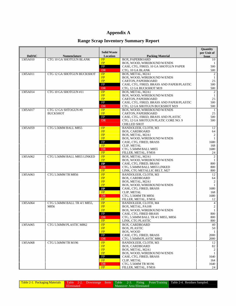
Table 2-1. Packaging Materials Table 2-2. Downrange ItemsEliminated
Table 2-3. Firing Point/TrainingManeuver Area Eliminated
Table 2-4. Residues Sampled.
Appendix A
Range Scrap Inventory Summary Report
DoDAC NomenclatureSolid Waste
Location Packing Material
Quantityper Unit of
Issue1305A010 CTG 10 GA SHOTGUN BLANK FP BOX, PAPERBOARD 10
FP BOX, WOOD, WIREBOUND W/ENDS 1FP CASE, CTG, FIRED, 10 GA SHOTGUN PAPER 500DR CTG, 10 GA BLANK 500
1305A011 CTG 12 GA SHOTGUN BUCKSHOT FP BOX, METAL, M2A1 2FP BOX, WOOD, WIREBOUND W/ENDS 1FP CARTON, PAPERBOARD 25FP CASE, CTG, FIRED, BRASS AND PAPER/PLASTIC 500DR CTG, 12 GA BUCKSHOT M19 500
1305A014 CTG 10 GA SHOTGUN #11 FP BOX, METAL, M2A1 2FP BOX, WOOD, WIREBOUND W/ENDS 1FP CARTON, PAPERBOARD 25FP CASE, CTG, FIRED, BRASS AND PAPER/PLASTIC 500DR CTG, 12 GA SHOTGUN BUCKSHOT M19 500
1305A017 CTG 12 GA SHTOGUN #9 FP BOX, WOOD, WIREBOUND W/ENDS 1BUCKSHOT FP CARTON, PAPERBOARD 25
FP CASE, CTG, FIRED, BRASS AND PLASTIC 500DR CTG, 12 GA SHOTGUN PLATIC CORE NO. 9
CHILLED SHOT500
1305A059 CTG 5.56MM BALL M855 FP BANDOLEER, CLOTH, M3 12FP BOX, CARDBOARD 64FP BOX, METAL, M2A1 2FP BOX, WOOD, WIREBOUND W/ENDS 1FP CASE, CTG, FIRED, BRASS 1680FP CLIP, METAL 168DR CTG, 5.56MM BALL M855 1680FP FILLER, METAL, F/M16 24
1305A062 CTG 5.56MM BALL M855 LINKED FP BOX, METAL, M2A1 2FP BOX, WOOD, WIREBOUND W/ENDS 1FP CASE, CTG, FIRED, BRASS 800DR CTG, 5.56MM BALL M855 LINKED 800FP LINK, CTG METALLIC BELT, M27 800
1305A063 CTG 5.56MM TR M856 FP BANDOLEER, CLOTH, M3 12FP BOX, CARDBOARD 64FP BOX, METAL, M2A1 2FP BOX, WOOD, WIREBOUND W/ENDS 1FP CASE, CTG, FIRED, BRASS 1680FP CLIP, METAL 168DR CTG, 5.56MM TR M856 1680FP FILLER, METAL, F/M16 12
1305A064 CTG 5.56MM BALL TR 4/1 M855, FP BANDOLEER, CLOTH, M4 4M856 FP BOX, METAL, PA108 2
FP BOX, WOOD, WIREBOUND W/ENDS 1FP CASE, CTG, FIRED BRASS 800DR CTG, 5.56MM BALL TR 4/1 M855, M856 800FP LINK, CTG PLASTIC 800
1305A065 CTG 5.56MM PLASTIC M862 FP BOX, CARDBOARD 40FP BOX, PLASTIC 50FP BOX, WOOD 1FP CASE, CTG, FIRED, BRASS 2000DR CTG, 5.56MM PLASTIC M862 2000
1305A068 CTG 5.56MM TR M196 FP BANDOLEER, CLOTH, M3 12FP BOX, CARDBOARD 82FP BOX, METAL, M2A1 2FP BOX, WOOD, WIREBOUND W/ENDS 1FP CASE, CTG, FIRED, BRASS 1640FP CLIP, METAL 164DR CTG, 5.56MM TR M196 1640FP FILLER, METAL, F/M16 24
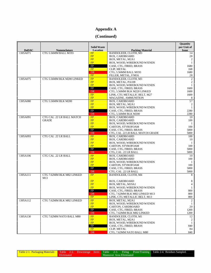
Table 2-1. Packaging Materials Table 2-2. Downrange ItemsEliminated
Table 2-3. Firing Point/TrainingManeuver Area Eliminated
Table 2-4. Residues Sampled.
Appendix A
(Continued)
DoDAC NomenclatureSolid Waste
Location Packing Material
Quantityper Unit of
Issue1305A071 CTG 5.56MM BALL M193 FP BANDOLEER, CLOTH, M3 14
FP BOX, CARDBOARD 28FP BOX, METAL, M2A1 2FP BOX, WOOD, WIREBOUND W/ENDS 1FP CASE, CTG, FIRED, BRASS 1680FP CLIP, METAL 168DR CTG, 5.56MM BALL M193 1680FP FILLER, METAL, F/M16 28
1305A075 CTG 5.56MM BLK M200 LINKED FP BANDOLEER, CLOTH, M3 2FP BOX, METAL, PA108 2FP BOX, WOOD, WIREBOUND W/ENDS 1FP CASE, CTG, FIRED, BRASS 1600DR CTG, 5.56MM BLK M220 LINKED 1600FP LINK, CTG METALLIC BELT, M27 1600FP MAGAZINE, AMMUNITION 8
1305A080 CTG 5.56MM BLK M200 FP BOX, CARDBOARD 57FP BOX, METAL, M2A1 2FP BOX, WOOD, WIREBOUND W/ENDS 1FP CASE, CTG, FIRED, BRASS 2280DR CTG, 5.56MM BLK M200 2280
1305A091 CTG CAL .22 LR BALL MATCH FP BOX, CARDBOARD 10GRADE FP BOX, CARDBOARD 100
FP BOX, WOOD, WIREBOUND W/ENDS 1FP CARTON, STYROFOAM 100FP CASE, CTG, FIRED, BRASS 5000DR CTG, CAL .22 LR BALL MATCH GRADE 5000
1305A093 CTG CAL .22 LR BALL FP BOX, CARDBOARD 100FP BOX, CARDBOARD 10FP BOX, WOOD, WIREBOUND W/ENDS 1FP CARTON, STYROFOAM 100FP CASE, CTG, FIRED, BRASS 5000DR CTG, CAL .22 LR BALL 5000
1305A106 CTG CAL .22 LR BALL FP BOX, CARDBOARD 10FP BOX, CARDBOARD 100FP BOX, WOOD, WIREBOUND W/ENDS 1FP CARTON, STYROFOAM 100FP CASE, CTG, FIRED, BRASS 5000DR CTG, CAL .22 LR BALL 5000
1305A111 CTG 7.62MM BLK M82 LINKEDM13
FP BANDOLEER, CLOTH, M4 8
FP BOX, CARDBOARD 8FP BOX, METAL, M19A1 4FP BOX, WOOD, WIREBOUND W/ENDS 1FP CASE, CTG, FIRED, BRASS 800DR CTG, 7.62MM BLK M82 LINKED M13 800FP LINK, CTG METALLIC BELT, M13 800
1305A112 CTG 7.62MM BLK M82 LINKED FP BOX, METAL, M2A1 2FP BOX, WOOD, WIREBOUND W/ENDS 1FP CARTON, CARDBOARD 20FP CASE, CTG, FIRED, BRASS 1200DR CTG, 7.62MM BLK M82 LINKED 1200
1305A130 CTG 7.62MM NATO BALL M80 FP BANDOLEER, CLOTH, M1 12FP BOX, METAL, M2A1 2FP BOX, WOOD, WIREBOUND W/ENDS 1FP CASE, CTG, FIRED, BRASS 840FP CLIP, METAL 84DR CTG, 7.62MM NATO BALL M80 840
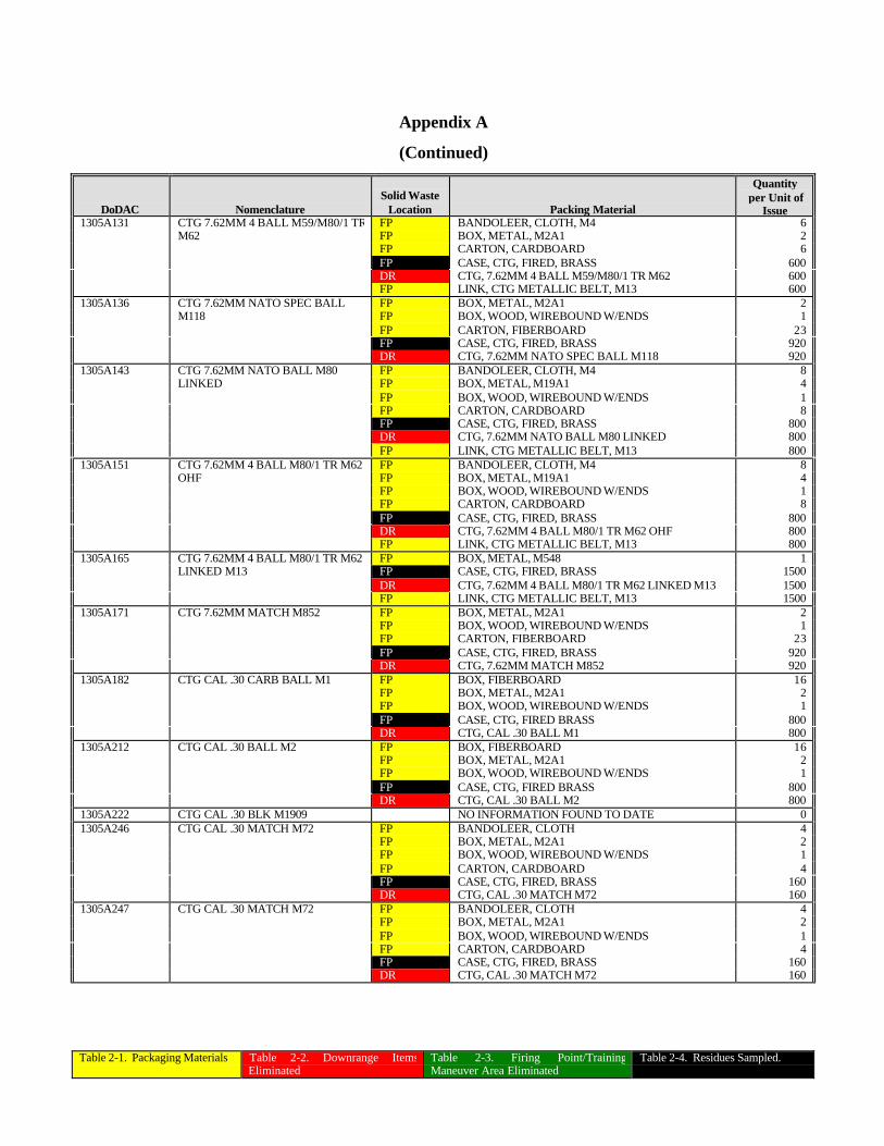
Table 2-1. Packaging Materials Table 2-2. Downrange ItemsEliminated
Table 2-3. Firing Point/TrainingManeuver Area Eliminated
Table 2-4. Residues Sampled.
Appendix A
(Continued)
DoDAC NomenclatureSolid Waste
Location Packing Material
Quantityper Unit of
Issue1305A131 CTG 7.62MM 4 BALL M59/M80/1 TR FP BANDOLEER, CLOTH, M4 6
M62 FP BOX, METAL, M2A1 2FP CARTON, CARDBOARD 6FP CASE, CTG, FIRED, BRASS 600DR CTG, 7.62MM 4 BALL M59/M80/1 TR M62 600FP LINK, CTG METALLIC BELT, M13 600
1305A136 CTG 7.62MM NATO SPEC BALL FP BOX, METAL, M2A1 2M118 FP BOX, WOOD, WIREBOUND W/ENDS 1
FP CARTON, FIBERBOARD 23FP CASE, CTG, FIRED, BRASS 920DR CTG, 7.62MM NATO SPEC BALL M118 920
1305A143 CTG 7.62MM NATO BALL M80 FP BANDOLEER, CLOTH, M4 8LINKED FP BOX, METAL, M19A1 4
FP BOX, WOOD, WIREBOUND W/ENDS 1FP CARTON, CARDBOARD 8FP CASE, CTG, FIRED, BRASS 800DR CTG, 7.62MM NATO BALL M80 LINKED 800FP LINK, CTG METALLIC BELT, M13 800
1305A151 CTG 7.62MM 4 BALL M80/1 TR M62 FP BANDOLEER, CLOTH, M4 8OHF FP BOX, METAL, M19A1 4
FP BOX, WOOD, WIREBOUND W/ENDS 1FP CARTON, CARDBOARD 8FP CASE, CTG, FIRED, BRASS 800DR CTG, 7.62MM 4 BALL M80/1 TR M62 OHF 800FP LINK, CTG METALLIC BELT, M13 800
1305A165 CTG 7.62MM 4 BALL M80/1 TR M62 FP BOX, METAL, M548 1LINKED M13 FP CASE, CTG, FIRED, BRASS 1500
DR CTG, 7.62MM 4 BALL M80/1 TR M62 LINKED M13 1500FP LINK, CTG METALLIC BELT, M13 1500
1305A171 CTG 7.62MM MATCH M852 FP BOX, METAL, M2A1 2FP BOX, WOOD, WIREBOUND W/ENDS 1FP CARTON, FIBERBOARD 23FP CASE, CTG, FIRED, BRASS 920DR CTG, 7.62MM MATCH M852 920
1305A182 CTG CAL .30 CARB BALL M1 FP BOX, FIBERBOARD 16FP BOX, METAL, M2A1 2FP BOX, WOOD, WIREBOUND W/ENDS 1FP CASE, CTG, FIRED BRASS 800DR CTG, CAL .30 BALL M1 800
1305A212 CTG CAL .30 BALL M2 FP BOX, FIBERBOARD 16FP BOX, METAL, M2A1 2FP BOX, WOOD, WIREBOUND W/ENDS 1FP CASE, CTG, FIRED BRASS 800DR CTG, CAL .30 BALL M2 800
1305A222 CTG CAL .30 BLK M1909 NO INFORMATION FOUND TO DATE 01305A246 CTG CAL .30 MATCH M72 FP BANDOLEER, CLOTH 4
FP BOX, METAL, M2A1 2FP BOX, WOOD, WIREBOUND W/ENDS 1FP CARTON, CARDBOARD 4FP CASE, CTG, FIRED, BRASS 160DR CTG, CAL .30 MATCH M72 160
1305A247 CTG CAL .30 MATCH M72 FP BANDOLEER, CLOTH 4FP BOX, METAL, M2A1 2FP BOX, WOOD, WIREBOUND W/ENDS 1FP CARTON, CARDBOARD 4FP CASE, CTG, FIRED, BRASS 160DR CTG, CAL .30 MATCH M72 160
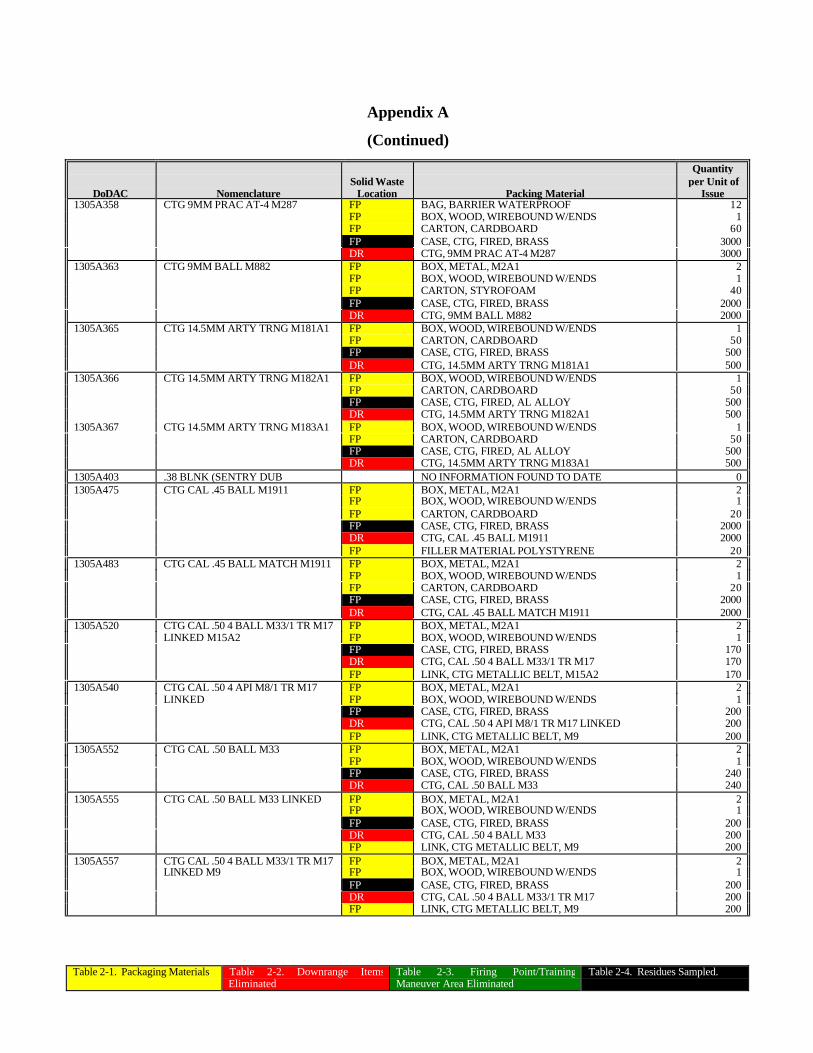
Table 2-1. Packaging Materials Table 2-2. Downrange ItemsEliminated
Table 2-3. Firing Point/TrainingManeuver Area Eliminated
Table 2-4. Residues Sampled.
Appendix A
(Continued)
DoDAC NomenclatureSolid Waste
Location Packing Material
Quantityper Unit of
Issue1305A358 CTG 9MM PRAC AT-4 M287 FP BAG, BARRIER WATERPROOF 12
FP BOX, WOOD, WIREBOUND W/ENDS 1FP CARTON, CARDBOARD 60FP CASE, CTG, FIRED, BRASS 3000DR CTG, 9MM PRAC AT-4 M287 3000
1305A363 CTG 9MM BALL M882 FP BOX, METAL, M2A1 2FP BOX, WOOD, WIREBOUND W/ENDS 1FP CARTON, STYROFOAM 40FP CASE, CTG, FIRED, BRASS 2000DR CTG, 9MM BALL M882 2000
1305A365 CTG 14.5MM ARTY TRNG M181A1 FP BOX, WOOD, WIREBOUND W/ENDS 1FP CARTON, CARDBOARD 50FP CASE, CTG, FIRED, BRASS 500DR CTG, 14.5MM ARTY TRNG M181A1 500
1305A366 CTG 14.5MM ARTY TRNG M182A1 FP BOX, WOOD, WIREBOUND W/ENDS 1FP CARTON, CARDBOARD 50FP CASE, CTG, FIRED, AL ALLOY 500DR CTG, 14.5MM ARTY TRNG M182A1 500
1305A367 CTG 14.5MM ARTY TRNG M183A1 FP BOX, WOOD, WIREBOUND W/ENDS 1FP CARTON, CARDBOARD 50FP CASE, CTG, FIRED, AL ALLOY 500DR CTG, 14.5MM ARTY TRNG M183A1 500
1305A403 .38 BLNK (SENTRY DUB NO INFORMATION FOUND TO DATE 01305A475 CTG CAL .45 BALL M1911 FP BOX, METAL, M2A1 2
FP BOX, WOOD, WIREBOUND W/ENDS 1FP CARTON, CARDBOARD 20FP CASE, CTG, FIRED, BRASS 2000DR CTG, CAL .45 BALL M1911 2000FP FILLER MATERIAL POLYSTYRENE 20
1305A483 CTG CAL .45 BALL MATCH M1911 FP BOX, METAL, M2A1 2FP BOX, WOOD, WIREBOUND W/ENDS 1FP CARTON, CARDBOARD 20FP CASE, CTG, FIRED, BRASS 2000DR CTG, CAL .45 BALL MATCH M1911 2000
1305A520 CTG CAL .50 4 BALL M33/1 TR M17 FP BOX, METAL, M2A1 2LINKED M15A2 FP BOX, WOOD, WIREBOUND W/ENDS 1
FP CASE, CTG, FIRED, BRASS 170DR CTG, CAL .50 4 BALL M33/1 TR M17 170FP LINK, CTG METALLIC BELT, M15A2 170
1305A540 CTG CAL .50 4 API M8/1 TR M17 FP BOX, METAL, M2A1 2LINKED FP BOX, WOOD, WIREBOUND W/ENDS 1
FP CASE, CTG, FIRED, BRASS 200DR CTG, CAL .50 4 API M8/1 TR M17 LINKED 200FP LINK, CTG METALLIC BELT, M9 200
1305A552 CTG CAL .50 BALL M33 FP BOX, METAL, M2A1 2FP BOX, WOOD, WIREBOUND W/ENDS 1FP CASE, CTG, FIRED, BRASS 240DR CTG, CAL .50 BALL M33 240
1305A555 CTG CAL .50 BALL M33 LINKED FP BOX, METAL, M2A1 2FP BOX, WOOD, WIREBOUND W/ENDS 1FP CASE, CTG, FIRED, BRASS 200DR CTG, CAL .50 4 BALL M33 200FP LINK, CTG METALLIC BELT, M9 200
1305A557 CTG CAL .50 4 BALL M33/1 TR M17 FP BOX, METAL, M2A1 2LINKED M9 FP BOX, WOOD, WIREBOUND W/ENDS 1
FP CASE, CTG, FIRED, BRASS 200DR CTG, CAL .50 4 BALL M33/1 TR M17 200FP LINK, CTG METALLIC BELT, M9 200
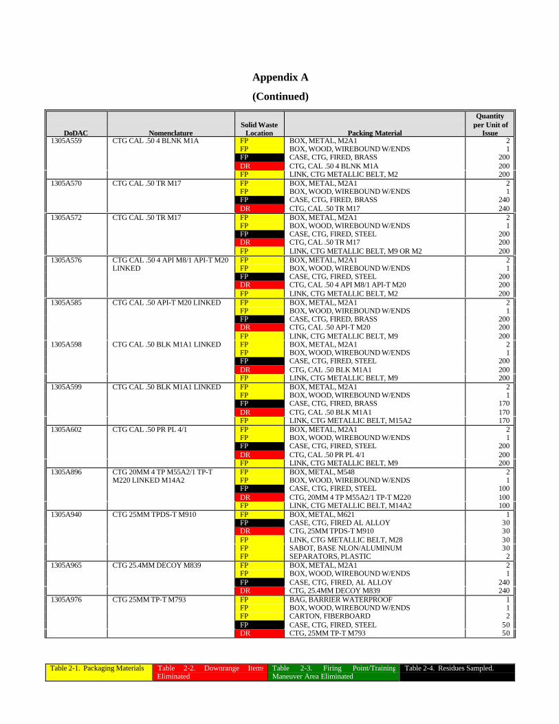
Table 2-1. Packaging Materials Table 2-2. Downrange ItemsEliminated
Table 2-3. Firing Point/TrainingManeuver Area Eliminated
Table 2-4. Residues Sampled.
Appendix A
(Continued)
DoDAC NomenclatureSolid Waste
Location Packing Material
Quantityper Unit of
Issue1305A559 CTG CAL .50 4 BLNK M1A FP BOX, METAL, M2A1 2
FP BOX, WOOD, WIREBOUND W/ENDS 1FP CASE, CTG, FIRED, BRASS 200DR CTG, CAL .50 4 BLNK M1A 200FP LINK, CTG METALLIC BELT, M2 200
1305A570 CTG CAL .50 TR M17 FP BOX, METAL, M2A1 2FP BOX, WOOD, WIREBOUND W/ENDS 1FP CASE, CTG, FIRED, BRASS 240DR CTG, CAL .50 TR M17 240
1305A572 CTG CAL .50 TR M17 FP BOX, METAL, M2A1 2FP BOX, WOOD, WIREBOUND W/ENDS 1FP CASE, CTG, FIRED, STEEL 200DR CTG, CAL .50 TR M17 200FP LINK, CTG METALLIC BELT, M9 OR M2 200
1305A576 CTG CAL .50 4 API M8/1 API-T M20 FP BOX, METAL, M2A1 2LINKED FP BOX, WOOD, WIREBOUND W/ENDS 1
FP CASE, CTG, FIRED, STEEL 200DR CTG, CAL .50 4 API M8/1 API-T M20 200FP LINK, CTG METALLIC BELT, M2 200
1305A585 CTG CAL .50 API-T M20 LINKED FP BOX, METAL, M2A1 2FP BOX, WOOD, WIREBOUND W/ENDS 1FP CASE, CTG, FIRED, BRASS 200DR CTG, CAL .50 API-T M20 200FP LINK, CTG METALLIC BELT, M9 200
1305A598 CTG CAL .50 BLK M1A1 LINKED FP BOX, METAL, M2A1 2FP BOX, WOOD, WIREBOUND W/ENDS 1FP CASE, CTG, FIRED, STEEL 200DR CTG, CAL .50 BLK M1A1 200FP LINK, CTG METALLIC BELT, M9 200
1305A599 CTG CAL .50 BLK M1A1 LINKED FP BOX, METAL, M2A1 2FP BOX, WOOD, WIREBOUND W/ENDS 1FP CASE, CTG, FIRED, BRASS 170DR CTG, CAL .50 BLK M1A1 170FP LINK, CTG METALLIC BELT, M15A2 170
1305A602 CTG CAL .50 PR PL 4/1 FP BOX, METAL, M2A1 2FP BOX, WOOD, WIREBOUND W/ENDS 1FP CASE, CTG, FIRED, STEEL 200DR CTG, CAL .50 PR PL 4/1 200FP LINK, CTG METALLIC BELT, M9 200
1305A896 CTG 20MM 4 TP M55A2/1 TP-T FP BOX, METAL, M548 2M220 LINKED M14A2 FP BOX, WOOD, WIREBOUND W/ENDS 1
FP CASE, CTG, FIRED, STEEL 100DR CTG, 20MM 4 TP M55A2/1 TP-T M220 100FP LINK, CTG METALLIC BELT, M14A2 100
1305A940 CTG 25MM TPDS-T M910 FP BOX, METAL, M621 1FP CASE, CTG, FIRED AL ALLOY 30DR CTG, 25MM TPDS-T M910 30FP LINK, CTG METALLIC BELT, M28 30FP SABOT, BASE NLON/ALUMINUM 30FP SEPARATORS, PLASTIC 2
1305A965 CTG 25.4MM DECOY M839 FP BOX, METAL, M2A1 2FP BOX, WOOD, WIREBOUND W/ENDS 1FP CASE, CTG, FIRED, AL ALLOY 240DR CTG, 25.4MM DECOY M839 240
1305A976 CTG 25MM TP-T M793 FP BAG, BARRIER WATERPROOF 1FP BOX, WOOD, WIREBOUND W/ENDS 1FP CARTON, FIBERBOARD 2FP CASE, CTG, FIRED, STEEL 50DR CTG, 25MM TP-T M793 50
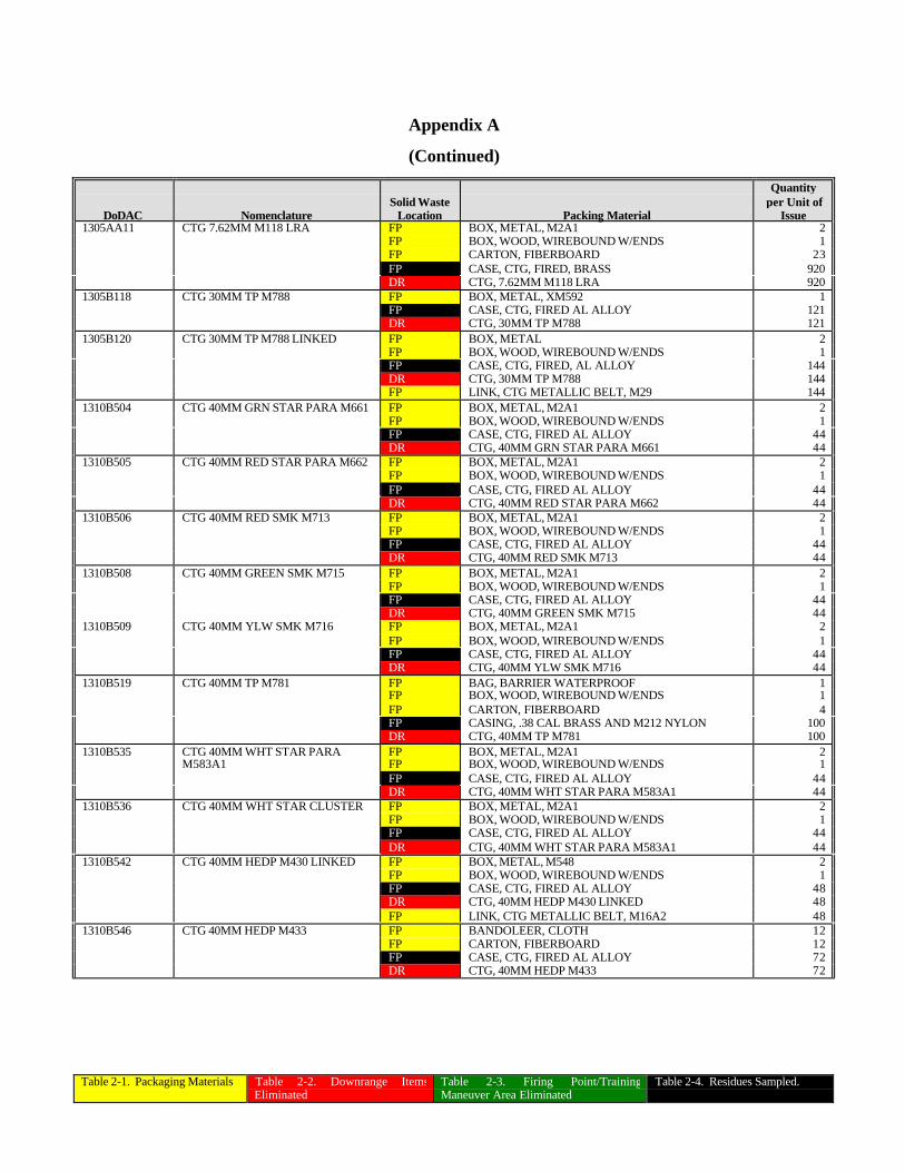
Table 2-1. Packaging Materials Table 2-2. Downrange ItemsEliminated
Table 2-3. Firing Point/TrainingManeuver Area Eliminated
Table 2-4. Residues Sampled.
Appendix A
(Continued)
DoDAC NomenclatureSolid Waste
Location Packing Material
Quantityper Unit of
Issue1305AA11 CTG 7.62MM M118 LRA FP BOX, METAL, M2A1 2
FP BOX, WOOD, WIREBOUND W/ENDS 1FP CARTON, FIBERBOARD 23FP CASE, CTG, FIRED, BRASS 920DR CTG, 7.62MM M118 LRA 920
1305B118 CTG 30MM TP M788 FP BOX, METAL, XM592 1FP CASE, CTG, FIRED AL ALLOY 121DR CTG, 30MM TP M788 121
1305B120 CTG 30MM TP M788 LINKED FP BOX, METAL 2FP BOX, WOOD, WIREBOUND W/ENDS 1FP CASE, CTG, FIRED, AL ALLOY 144DR CTG, 30MM TP M788 144FP LINK, CTG METALLIC BELT, M29 144
1310B504 CTG 40MM GRN STAR PARA M661 FP BOX, METAL, M2A1 2FP BOX, WOOD, WIREBOUND W/ENDS 1FP CASE, CTG, FIRED AL ALLOY 44DR CTG, 40MM GRN STAR PARA M661 44
1310B505 CTG 40MM RED STAR PARA M662 FP BOX, METAL, M2A1 2FP BOX, WOOD, WIREBOUND W/ENDS 1FP CASE, CTG, FIRED AL ALLOY 44DR CTG, 40MM RED STAR PARA M662 44
1310B506 CTG 40MM RED SMK M713 FP BOX, METAL, M2A1 2FP BOX, WOOD, WIREBOUND W/ENDS 1FP CASE, CTG, FIRED AL ALLOY 44DR CTG, 40MM RED SMK M713 44
1310B508 CTG 40MM GREEN SMK M715 FP BOX, METAL, M2A1 2FP BOX, WOOD, WIREBOUND W/ENDS 1FP CASE, CTG, FIRED AL ALLOY 44DR CTG, 40MM GREEN SMK M715 44
1310B509 CTG 40MM YLW SMK M716 FP BOX, METAL, M2A1 2FP BOX, WOOD, WIREBOUND W/ENDS 1FP CASE, CTG, FIRED AL ALLOY 44DR CTG, 40MM YLW SMK M716 44
1310B519 CTG 40MM TP M781 FP BAG, BARRIER WATERPROOF 1FP BOX, WOOD, WIREBOUND W/ENDS 1FP CARTON, FIBERBOARD 4FP CASING, .38 CAL BRASS AND M212 NYLON 100DR CTG, 40MM TP M781 100
1310B535 CTG 40MM WHT STAR PARA FP BOX, METAL, M2A1 2M583A1 FP BOX, WOOD, WIREBOUND W/ENDS 1
FP CASE, CTG, FIRED AL ALLOY 44DR CTG, 40MM WHT STAR PARA M583A1 44
1310B536 CTG 40MM WHT STAR CLUSTER FP BOX, METAL, M2A1 2FP BOX, WOOD, WIREBOUND W/ENDS 1FP CASE, CTG, FIRED AL ALLOY 44DR CTG, 40MM WHT STAR PARA M583A1 44
1310B542 CTG 40MM HEDP M430 LINKED FP BOX, METAL, M548 2FP BOX, WOOD, WIREBOUND W/ENDS 1FP CASE, CTG, FIRED AL ALLOY 48DR CTG, 40MM HEDP M430 LINKED 48FP LINK, CTG METALLIC BELT, M16A2 48
1310B546 CTG 40MM HEDP M433 FP BANDOLEER, CLOTH 12FP CARTON, FIBERBOARD 12FP CASE, CTG, FIRED AL ALLOY 72DR CTG, 40MM HEDP M433 72
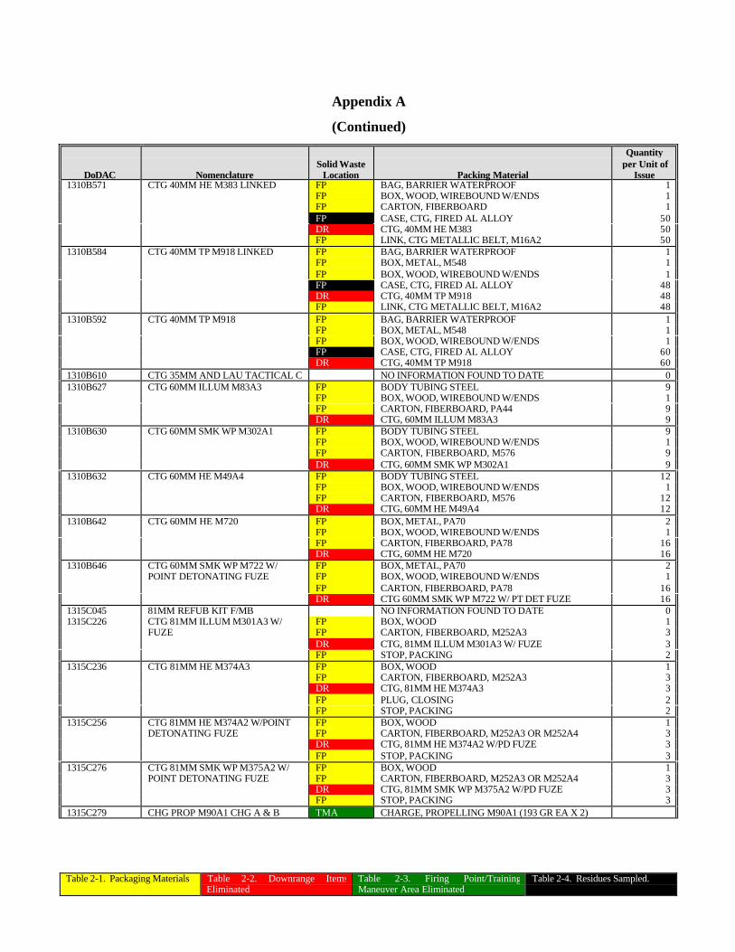
Table 2-1. Packaging Materials Table 2-2. Downrange ItemsEliminated
Table 2-3. Firing Point/TrainingManeuver Area Eliminated
Table 2-4. Residues Sampled.
Appendix A
(Continued)
DoDAC NomenclatureSolid Waste
Location Packing Material
Quantityper Unit of
Issue1310B571 CTG 40MM HE M383 LINKED FP BAG, BARRIER WATERPROOF 1
FP BOX, WOOD, WIREBOUND W/ENDS 1FP CARTON, FIBERBOARD 1FP CASE, CTG, FIRED AL ALLOY 50DR CTG, 40MM HE M383 50FP LINK, CTG METALLIC BELT, M16A2 50
1310B584 CTG 40MM TP M918 LINKED FP BAG, BARRIER WATERPROOF 1FP BOX, METAL, M548 1FP BOX, WOOD, WIREBOUND W/ENDS 1FP CASE, CTG, FIRED AL ALLOY 48DR CTG, 40MM TP M918 48FP LINK, CTG METALLIC BELT, M16A2 48
1310B592 CTG 40MM TP M918 FP BAG, BARRIER WATERPROOF 1FP BOX, METAL, M548 1FP BOX, WOOD, WIREBOUND W/ENDS 1FP CASE, CTG, FIRED AL ALLOY 60DR CTG, 40MM TP M918 60
1310B610 CTG 35MM AND LAU TACTICAL C NO INFORMATION FOUND TO DATE 01310B627 CTG 60MM ILLUM M83A3 FP BODY TUBING STEEL 9
FP BOX, WOOD, WIREBOUND W/ENDS 1FP CARTON, FIBERBOARD, PA44 9DR CTG, 60MM ILLUM M83A3 9
1310B630 CTG 60MM SMK WP M302A1 FP BODY TUBING STEEL 9FP BOX, WOOD, WIREBOUND W/ENDS 1FP CARTON, FIBERBOARD, M576 9DR CTG, 60MM SMK WP M302A1 9
1310B632 CTG 60MM HE M49A4 FP BODY TUBING STEEL 12FP BOX, WOOD, WIREBOUND W/ENDS 1FP CARTON, FIBERBOARD, M576 12DR CTG, 60MM HE M49A4 12
1310B642 CTG 60MM HE M720 FP BOX, METAL, PA70 2FP BOX, WOOD, WIREBOUND W/ENDS 1FP CARTON, FIBERBOARD, PA78 16DR CTG, 60MM HE M720 16
1310B646 CTG 60MM SMK WP M722 W/ FP BOX, METAL, PA70 2POINT DETONATING FUZE FP BOX, WOOD, WIREBOUND W/ENDS 1
FP CARTON, FIBERBOARD, PA78 16DR CTG 60MM SMK WP M722 W/ PT DET FUZE 16
1315C045 81MM REFUB KIT F/MB NO INFORMATION FOUND TO DATE 01315C226 CTG 81MM ILLUM M301A3 W/ FP BOX, WOOD 1
FUZE FP CARTON, FIBERBOARD, M252A3 3DR CTG, 81MM ILLUM M301A3 W/ FUZE 3FP STOP, PACKING 2
1315C236 CTG 81MM HE M374A3 FP BOX, WOOD 1FP CARTON, FIBERBOARD, M252A3 3DR CTG, 81MM HE M374A3 3FP PLUG, CLOSING 2FP STOP, PACKING 2
1315C256 CTG 81MM HE M374A2 W/POINT FP BOX, WOOD 1DETONATING FUZE FP CARTON, FIBERBOARD, M252A3 OR M252A4 3
DR CTG, 81MM HE M374A2 W/PD FUZE 3FP STOP, PACKING 3
1315C276 CTG 81MM SMK WP M375A2 W/ FP BOX, WOOD 1POINT DETONATING FUZE FP CARTON, FIBERBOARD, M252A3 OR M252A4 3
DR CTG, 81MM SMK WP M375A2 W/PD FUZE 3FP STOP, PACKING 3
1315C279 CHG PROP M90A1 CHG A & B TMA CHARGE, PROPELLING M90A1 (193 GR EA X 2)
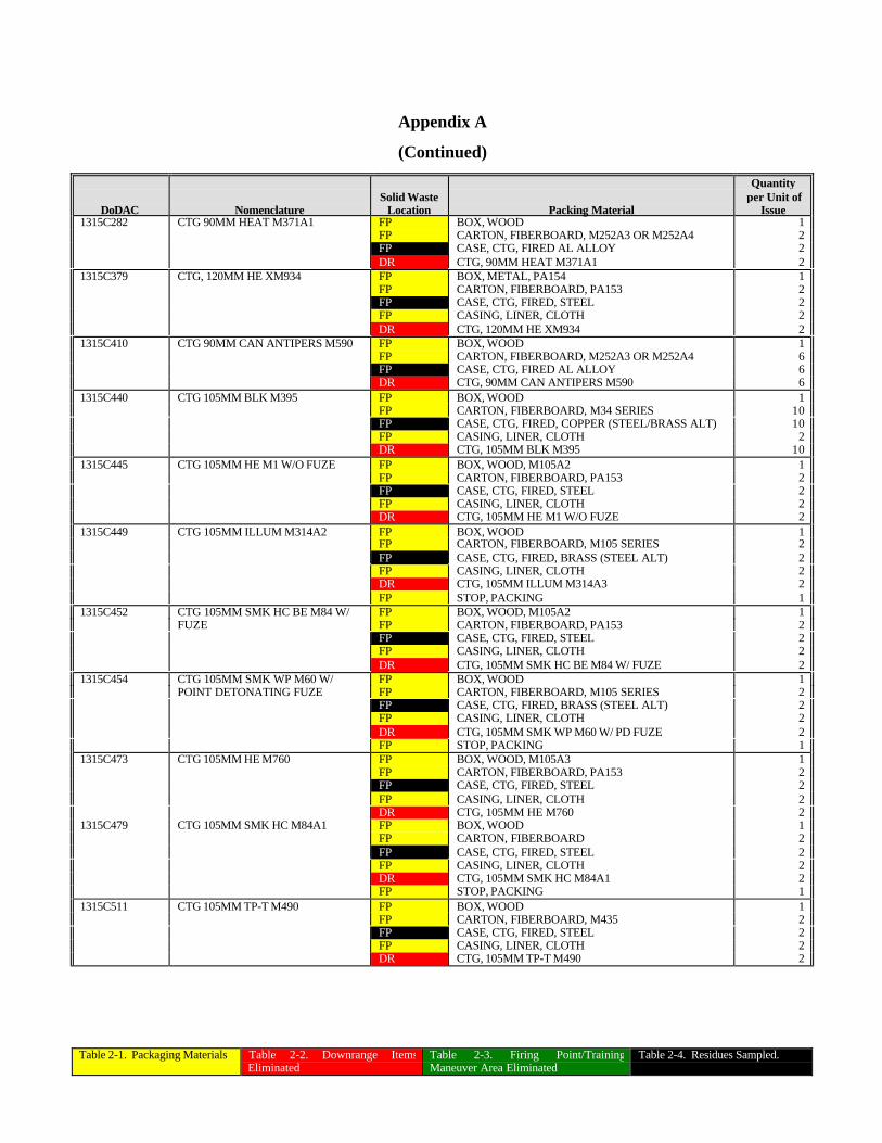
Table 2-1. Packaging Materials Table 2-2. Downrange ItemsEliminated
Table 2-3. Firing Point/TrainingManeuver Area Eliminated
Table 2-4. Residues Sampled.
Appendix A
(Continued)
DoDAC NomenclatureSolid Waste
Location Packing Material
Quantityper Unit of
Issue1315C282 CTG 90MM HEAT M371A1 FP BOX, WOOD 1
FP CARTON, FIBERBOARD, M252A3 OR M252A4 2FP CASE, CTG, FIRED AL ALLOY 2DR CTG, 90MM HEAT M371A1 2
1315C379 CTG, 120MM HE XM934 FP BOX, METAL, PA154 1FP CARTON, FIBERBOARD, PA153 2FP CASE, CTG, FIRED, STEEL 2FP CASING, LINER, CLOTH 2DR CTG, 120MM HE XM934 2
1315C410 CTG 90MM CAN ANTIPERS M590 FP BOX, WOOD 1FP CARTON, FIBERBOARD, M252A3 OR M252A4 6FP CASE, CTG, FIRED AL ALLOY 6DR CTG, 90MM CAN ANTIPERS M590 6
1315C440 CTG 105MM BLK M395 FP BOX, WOOD 1FP CARTON, FIBERBOARD, M34 SERIES 10FP CASE, CTG, FIRED, COPPER (STEEL/BRASS ALT) 10FP CASING, LINER, CLOTH 2DR CTG, 105MM BLK M395 10
1315C445 CTG 105MM HE M1 W/O FUZE FP BOX, WOOD, M105A2 1FP CARTON, FIBERBOARD, PA153 2FP CASE, CTG, FIRED, STEEL 2FP CASING, LINER, CLOTH 2DR CTG, 105MM HE M1 W/O FUZE 2
1315C449 CTG 105MM ILLUM M314A2 FP BOX, WOOD 1FP CARTON, FIBERBOARD, M105 SERIES 2FP CASE, CTG, FIRED, BRASS (STEEL ALT) 2FP CASING, LINER, CLOTH 2DR CTG, 105MM ILLUM M314A3 2FP STOP, PACKING 1
1315C452 CTG 105MM SMK HC BE M84 W/ FP BOX, WOOD, M105A2 1FUZE FP CARTON, FIBERBOARD, PA153 2
FP CASE, CTG, FIRED, STEEL 2FP CASING, LINER, CLOTH 2DR CTG, 105MM SMK HC BE M84 W/ FUZE 2
1315C454 CTG 105MM SMK WP M60 W/ FP BOX, WOOD 1POINT DETONATING FUZE FP CARTON, FIBERBOARD, M105 SERIES 2
FP CASE, CTG, FIRED, BRASS (STEEL ALT) 2FP CASING, LINER, CLOTH 2DR CTG, 105MM SMK WP M60 W/ PD FUZE 2FP STOP, PACKING 1
1315C473 CTG 105MM HE M760 FP BOX, WOOD, M105A3 1FP CARTON, FIBERBOARD, PA153 2FP CASE, CTG, FIRED, STEEL 2FP CASING, LINER, CLOTH 2DR CTG, 105MM HE M760 2
1315C479 CTG 105MM SMK HC M84A1 FP BOX, WOOD 1FP CARTON, FIBERBOARD 2FP CASE, CTG, FIRED, STEEL 2FP CASING, LINER, CLOTH 2DR CTG, 105MM SMK HC M84A1 2FP STOP, PACKING 1
1315C511 CTG 105MM TP-T M490 FP BOX, WOOD 1FP CARTON, FIBERBOARD, M435 2FP CASE, CTG, FIRED, STEEL 2FP CASING, LINER, CLOTH 2DR CTG, 105MM TP-T M490 2
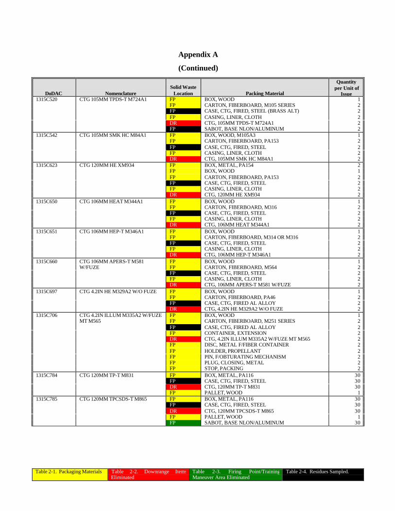
Table 2-1. Packaging Materials Table 2-2. Downrange ItemsEliminated
Table 2-3. Firing Point/TrainingManeuver Area Eliminated
Table 2-4. Residues Sampled.
Appendix A
(Continued)
DoDAC NomenclatureSolid Waste
Location Packing Material
Quantityper Unit of
Issue1315C520 CTG 105MM TPDS-T M724A1 FP BOX, WOOD 1
FP CARTON, FIBERBOARD, M105 SERIES 2FP CASE, CTG, FIRED, STEEL (BRASS ALT) 2FP CASING, LINER, CLOTH 2DR CTG, 105MM TPDS-T M724A1 2FP SABOT, BASE NLON/ALUMINUM 2
1315C542 CTG 105MM SMK HC M84A1 FP BOX, WOOD, M105A3 1FP CARTON, FIBERBOARD, PA153 2FP CASE, CTG, FIRED, STEEL 2FP CASING, LINER, CLOTH 2DR CTG, 105MM SMK HC M84A1 2
1315C623 CTG 120MM HE XM934 FP BOX, METAL, PA154 2FP BOX, WOOD 1FP CARTON, FIBERBOARD, PA153 2FP CASE, CTG, FIRED, STEEL 2FP CASING, LINER, CLOTH 2DR CTG, 120MM HE XM934 2
1315C650 CTG 106MM HEAT M344A1 FP BOX, WOOD 1FP CARTON, FIBERBOARD, M316 2FP CASE, CTG, FIRED, STEEL 2FP CASING, LINER, CLOTH 2DR CTG, 106MM HEAT M344A1 2
1315C651 CTG 106MM HEP-T M346A1 FP BOX, WOOD 1FP CARTON, FIBERBOARD, M314 OR M316 2FP CASE, CTG, FIRED, STEEL 2FP CASING, LINER, CLOTH 2DR CTG, 106MM HEP-T M346A1 2
1315C660 CTG 106MM APERS-T M581 FP BOX, WOOD 1W/FUZE FP CARTON, FIBERBOARD, M564 2
FP CASE, CTG, FIRED, STEEL 2FP CASING, LINER, CLOTH 2DR CTG, 106MM APERS-T M581 W/FUZE 2
1315C697 CTG 4.2IN HE M329A2 W/O FUZE FP BOX, WOOD 1FP CARTON, FIBERBOARD, PA46 2FP CASE, CTG, FIRED AL ALLOY 2DR CTG, 4.2IN HE M329A2 W/O FUZE 2
1315C706 CTG 4.2IN ILLUM M335A2 W/FUZE FP BOX, WOOD 1MT M565 FP CARTON, FIBERBOARD, M251 SERIES 2
FP CASE, CTG, FIRED AL ALLOY 2FP CONTAINER, EXTENSION 2DR CTG, 4.2IN ILLUM M335A2 W/FUZE MT M565 2FP DISC, METAL F/FIBER CONTAINER 2FP HOLDER, PROPELLANT 2FP PIN, F/OBTURATING MECHANISM 2FP PLUG, CLOSING, METAL 2FP STOP, PACKING 2
1315C784 CTG 120MM TP-T M831 FP BOX, METAL, PA116 30FP CASE, CTG, FIRED, STEEL 30DR CTG, 120MM TP-T M831 30FP PALLET, WOOD 1
1315C785 CTG 120MM TPCSDS-T M865 FP BOX, METAL, PA116 30FP CASE, CTG, FIRED, STEEL 30DR CTG, 120MM TPCSDS-T M865 30FP PALLET, WOOD 1FP SABOT, BASE NLON/ALUMINUM 30
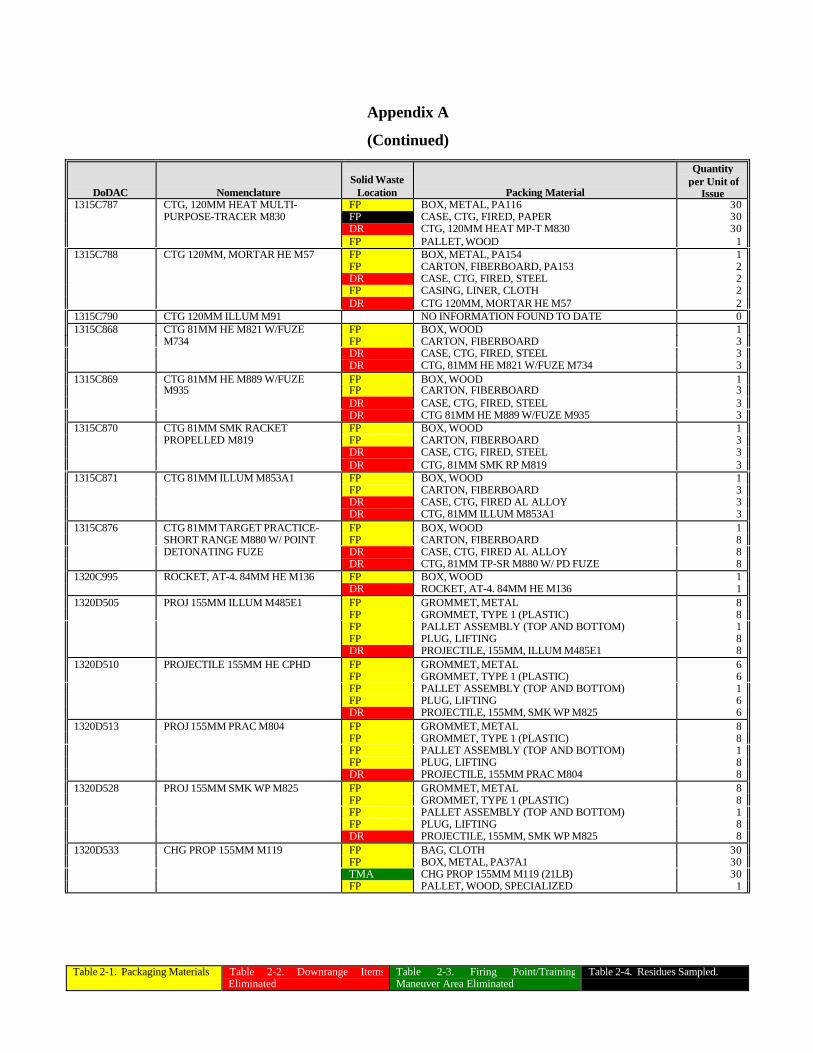
Table 2-1. Packaging Materials Table 2-2. Downrange ItemsEliminated
Table 2-3. Firing Point/TrainingManeuver Area Eliminated
Table 2-4. Residues Sampled.
Appendix A
(Continued)
DoDAC NomenclatureSolid Waste
Location Packing Material
Quantityper Unit of
Issue1315C787 CTG, 120MM HEAT MULTI- FP BOX, METAL, PA116 30
PURPOSE-TRACER M830 FP CASE, CTG, FIRED, PAPER 30DR CTG, 120MM HEAT MP-T M830 30FP PALLET, WOOD 1
1315C788 CTG 120MM, MORTAR HE M57 FP BOX, METAL, PA154 1FP CARTON, FIBERBOARD, PA153 2DR CASE, CTG, FIRED, STEEL 2FP CASING, LINER, CLOTH 2DR CTG 120MM, MORTAR HE M57 2
1315C790 CTG 120MM ILLUM M91 NO INFORMATION FOUND TO DATE 01315C868 CTG 81MM HE M821 W/FUZE FP BOX, WOOD 1
M734 FP CARTON, FIBERBOARD 3DR CASE, CTG, FIRED, STEEL 3DR CTG, 81MM HE M821 W/FUZE M734 3
1315C869 CTG 81MM HE M889 W/FUZE FP BOX, WOOD 1M935 FP CARTON, FIBERBOARD 3
DR CASE, CTG, FIRED, STEEL 3DR CTG 81MM HE M889 W/FUZE M935 3
1315C870 CTG 81MM SMK RACKET FP BOX, WOOD 1PROPELLED M819 FP CARTON, FIBERBOARD 3
DR CASE, CTG, FIRED, STEEL 3DR CTG, 81MM SMK RP M819 3
1315C871 CTG 81MM ILLUM M853A1 FP BOX, WOOD 1FP CARTON, FIBERBOARD 3DR CASE, CTG, FIRED AL ALLOY 3DR CTG, 81MM ILLUM M853A1 3
1315C876 CTG 81MM TARGET PRACTICE- FP BOX, WOOD 1SHORT RANGE M880 W/ POINT FP CARTON, FIBERBOARD 8DETONATING FUZE DR CASE, CTG, FIRED AL ALLOY 8
DR CTG, 81MM TP-SR M880 W/ PD FUZE 81320C995 ROCKET, AT-4. 84MM HE M136 FP BOX, WOOD 1
DR ROCKET, AT-4. 84MM HE M136 11320D505 PROJ 155MM ILLUM M485E1 FP GROMMET, METAL 8
FP GROMMET, TYPE 1 (PLASTIC) 8FP PALLET ASSEMBLY (TOP AND BOTTOM) 1FP PLUG, LIFTING 8DR PROJECTILE, 155MM, ILLUM M485E1 8
1320D510 PROJECTILE 155MM HE CPHD FP GROMMET, METAL 6FP GROMMET, TYPE 1 (PLASTIC) 6FP PALLET ASSEMBLY (TOP AND BOTTOM) 1FP PLUG, LIFTING 6DR PROJECTILE, 155MM, SMK WP M825 6
1320D513 PROJ 155MM PRAC M804 FP GROMMET, METAL 8FP GROMMET, TYPE 1 (PLASTIC) 8FP PALLET ASSEMBLY (TOP AND BOTTOM) 1FP PLUG, LIFTING 8DR PROJECTILE, 155MM PRAC M804 8
1320D528 PROJ 155MM SMK WP M825 FP GROMMET, METAL 8FP GROMMET, TYPE 1 (PLASTIC) 8FP PALLET ASSEMBLY (TOP AND BOTTOM) 1FP PLUG, LIFTING 8DR PROJECTILE, 155MM, SMK WP M825 8
1320D533 CHG PROP 155MM M119 FP BAG, CLOTH 30FP BOX, METAL, PA37A1 30TMA CHG PROP 155MM M119 (21LB) 30FP PALLET, WOOD, SPECIALIZED 1
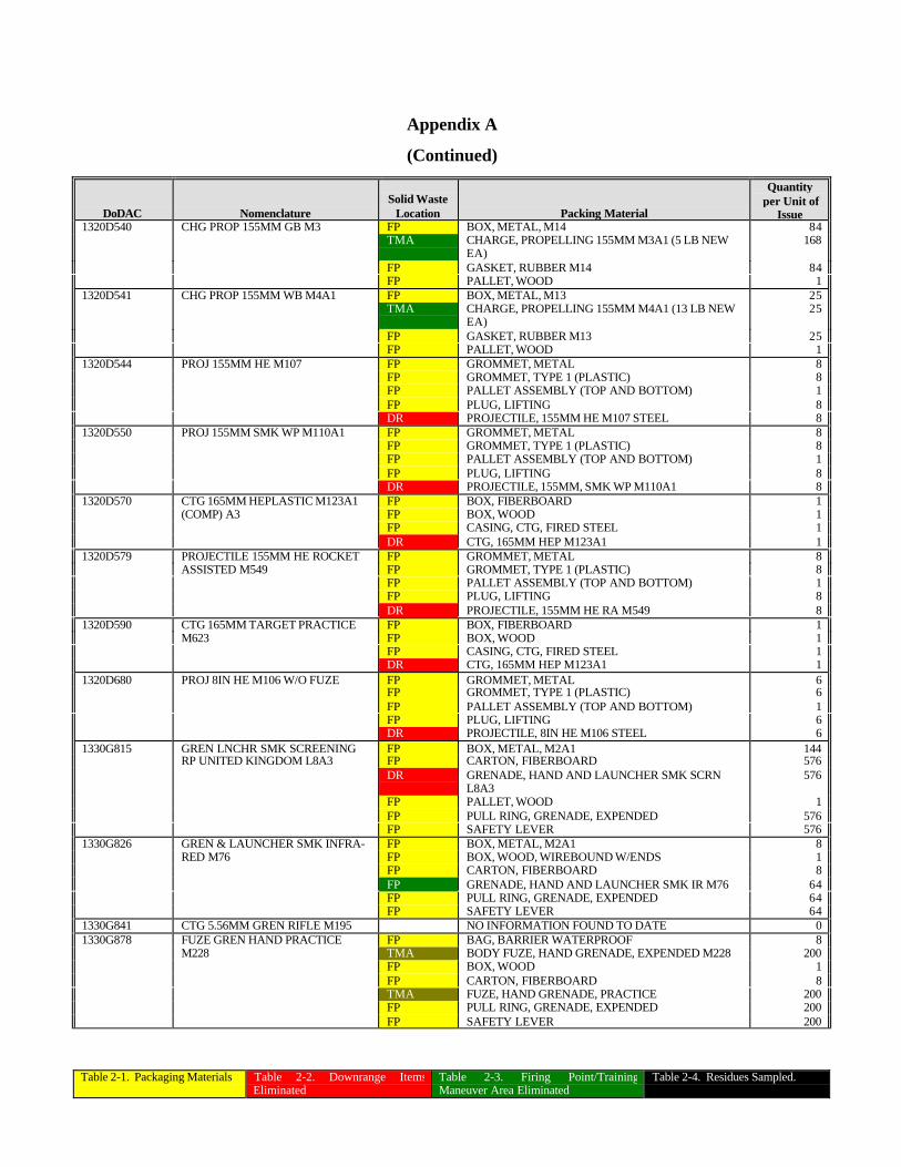
Table 2-1. Packaging Materials Table 2-2. Downrange ItemsEliminated
Table 2-3. Firing Point/TrainingManeuver Area Eliminated
Table 2-4. Residues Sampled.
Appendix A
(Continued)
DoDAC NomenclatureSolid Waste
Location Packing Material
Quantityper Unit of
Issue1320D540 CHG PROP 155MM GB M3 FP BOX, METAL, M14 84
TMA CHARGE, PROPELLING 155MM M3A1 (5 LB NEWEA)
168
FP GASKET, RUBBER M14 84FP PALLET, WOOD 1
1320D541 CHG PROP 155MM WB M4A1 FP BOX, METAL, M13 25TMA CHARGE, PROPELLING 155MM M4A1 (13 LB NEW
EA)25
FP GASKET, RUBBER M13 25FP PALLET, WOOD 1
1320D544 PROJ 155MM HE M107 FP GROMMET, METAL 8FP GROMMET, TYPE 1 (PLASTIC) 8FP PALLET ASSEMBLY (TOP AND BOTTOM) 1FP PLUG, LIFTING 8DR PROJECTILE, 155MM HE M107 STEEL 8
1320D550 PROJ 155MM SMK WP M110A1 FP GROMMET, METAL 8FP GROMMET, TYPE 1 (PLASTIC) 8FP PALLET ASSEMBLY (TOP AND BOTTOM) 1FP PLUG, LIFTING 8DR PROJECTILE, 155MM, SMK WP M110A1 8
1320D570 CTG 165MM HEPLASTIC M123A1 FP BOX, FIBERBOARD 1(COMP) A3 FP BOX, WOOD 1
FP CASING, CTG, FIRED STEEL 1DR CTG, 165MM HEP M123A1 1
1320D579 PROJECTILE 155MM HE ROCKET FP GROMMET, METAL 8ASSISTED M549 FP GROMMET, TYPE 1 (PLASTIC) 8
FP PALLET ASSEMBLY (TOP AND BOTTOM) 1FP PLUG, LIFTING 8DR PROJECTILE, 155MM HE RA M549 8
1320D590 CTG 165MM TARGET PRACTICE FP BOX, FIBERBOARD 1M623 FP BOX, WOOD 1
FP CASING, CTG, FIRED STEEL 1DR CTG, 165MM HEP M123A1 1
1320D680 PROJ 8IN HE M106 W/O FUZE FP GROMMET, METAL 6FP GROMMET, TYPE 1 (PLASTIC) 6FP PALLET ASSEMBLY (TOP AND BOTTOM) 1FP PLUG, LIFTING 6DR PROJECTILE, 8IN HE M106 STEEL 6
1330G815 GREN LNCHR SMK SCREENING FP BOX, METAL, M2A1 144RP UNITED KINGDOM L8A3 FP CARTON, FIBERBOARD 576
DR GRENADE, HAND AND LAUNCHER SMK SCRNL8A3
576
FP PALLET, WOOD 1FP PULL RING, GRENADE, EXPENDED 576FP SAFETY LEVER 576
1330G826 GREN & LAUNCHER SMK INFRA- FP BOX, METAL, M2A1 8RED M76 FP BOX, WOOD, WIREBOUND W/ENDS 1
FP CARTON, FIBERBOARD 8FP GRENADE, HAND AND LAUNCHER SMK IR M76 64FP PULL RING, GRENADE, EXPENDED 64FP SAFETY LEVER 64
1330G841 CTG 5.56MM GREN RIFLE M195 NO INFORMATION FOUND TO DATE 01330G878 FUZE GREN HAND PRACTICE FP BAG, BARRIER WATERPROOF 8
M228 TMA BODY FUZE, HAND GRENADE, EXPENDED M228 200FP BOX, WOOD 1FP CARTON, FIBERBOARD 8TMA FUZE, HAND GRENADE, PRACTICE 200FP PULL RING, GRENADE, EXPENDED 200FP SAFETY LEVER 200
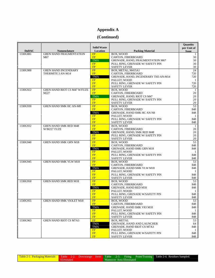
Table 2-1. Packaging Materials Table 2-2. Downrange ItemsEliminated
Table 2-3. Firing Point/TrainingManeuver Area Eliminated
Table 2-4. Residues Sampled.
Appendix A
(Continued)
DoDAC NomenclatureSolid Waste
Location Packing Material
Quantityper Unit of
Issue1330G881 GREN HAND FRAGMENTATION FP BOX, WOOD 1
M67 FP CARTON, FIBERBOARD 30TMA GRENADE, HAND, FRAGMENTATION M67 30FP PULL RING, GRENADE W/ SAFETY PIN 30FP SAFETY LEVER 30
1330G900 GREN HAND INCENDIARY FP BOX, METAL, M415A1 24THERMITE 3 AN-M14 FP CARTON, FIBERBOARD 720
TMA GRENADE, HAND, INCENDIARY TH3 AN-M14 720FP PALLET, WOOD 1FP PULL RING, GRENADE W/ SAFETY PIN 720FP SAFETY LEVER 720
1330G922 GREN HAND RIOT CS M47 W/FUZE FP BOX, WOOD 1M227 FP CARTON, FIBERBOARD 20
TMA GRENADE, HAND, RIOT CS M47 20FP PULL RING, GRENADE W/ SAFETY PIN 20FP SAFETY LEVER 20
1330G930 GREN HAND SMK HC AN-M8 FP BOX, WOOD 53FP CARTON, FIBERBOARD 848TMA GRENADE, HAND SMK HC AN-N8 848FP PALLET, WOOD 1FP PULL RING, GRENADE W/ SAFETY PIN 848FP SAFETY LEVER 848
1330G932 GREN HAND SMK RED M48 FP BOX, WOOD 1W/M227 FUZE FP CARTON, FIBERBOARD 20
TMA GRENADE, HAND, SMK RED M48 20FP PULL RING, GRENADE W/ SAFETY PIN 20FP SAFETY LEVER 20
1330G940 GREN HAND SMK GRN M18 FP BOX, WOOD 53FP CARTON, FIBERBOARD 848TMA GRENADE, HAND SMK GRN M18 848FP PALLET, WOOD 1FP PULL RING, GRENADE W/ SAFETY PIN 848FP SAFETY LEVER 848
1330G945 GREN HAND SMK YLW M18 FP BOX, WOOD 53FP CARTON, FIBERBOARD 848TMA GRENADE, HAND SMK YLW M18 848FP PALLET, WOOD 1FP PULL RING, GRENADE W/ SAFETY PIN 848FP SAFETY LEVER 848
1330G950 GREN HAND SMK RED M18 FP BOX, WOOD 53FP CARTON, FIBERBOARD 848TMA GRENADE, HAND RED M18 848FP PALLET, WOOD 1FP PULL RING, GRENADE W/SAFETY PIN 848FP SAFETY LEVER 848
1330G955 GREN HAND SMK VIOLET M18 FP BOX, WOOD 53FP CARTON, FIBERBOARD 848TMA GRENADE, HAND SMK VIO M18 848FP PALLET, WOOD 1FP PULL RING, GRENADE W/ SAFETY PIN 848FP SAFETY LEVER 848
1330G963 GREN HAND RIOT CS M7A3 FP BOX, METAL 53TMA GRENADE, HAND AND LAUNCHER 64TMA GRENADE, HAND RIOT CS M7A3 848FP PALLET, WOOD 1FP PULL RING, GRENADE W/SAFETY PIN 848FP SAFETY LEVER 848
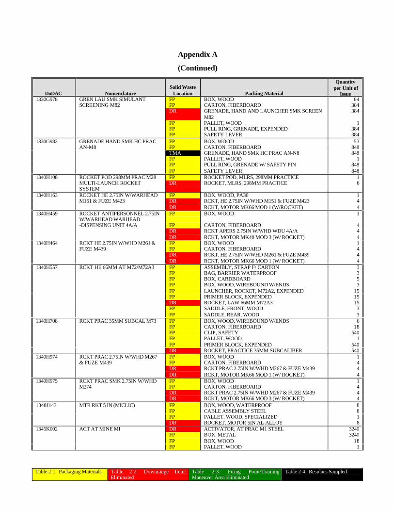
Table 2-1. Packaging Materials Table 2-2. Downrange ItemsEliminated
Table 2-3. Firing Point/TrainingManeuver Area Eliminated
Table 2-4. Residues Sampled.
Appendix A
(Continued)
DoDAC NomenclatureSolid Waste
Location Packing Material
Quantityper Unit of
Issue1330G978 GREN LAU SMK SIMULANT FP BOX, WOOD 64
SCREENING M82 FP CARTON, FIBERBOARD 384DR GRENADE, HAND AND LAUNCHER SMK SCREEN
M82384
FP PALLET, WOOD 1FP PULL RING, GRENADE, EXPENDED 384FP SAFETY LEVER 384
1330G982 GRENADE HAND SMK HC PRAC FP BOX, WOOD 53AN-M8 FP CARTON, FIBERBOARD 848
TMA GRENADE, HAND SMK HC PRAC AN-N8 848FP PALLET, WOOD 1FP PULL RING, GRENADE W/ SAFETY PIN 848FP SAFETY LEVER 848
1340H108 ROCKET POD 298MM PRAC M28 FP ROCKET POD, MLRS, 298MM PRACTICE 1MULTI-LAUNCH ROCKETSYSTEM
DR ROCKET, MLRS, 298MM PRACTICE 6
1340H163 ROCKET HE 2.75IN W/WARHEAD FP BOX, WOOD, PA30 1M151 & FUZE M423 DR RCKT, HE 2.75IN W/WHD M151 & FUZE M423 4
DR RCKT, MOTOR MK66 MOD 1 (W/ROCKET) 41340H459 ROCKET ANTIPERSONNEL 2.75IN
W/WARHEAD WARHEADFP BOX, WOOD 1
-DISPENSING UNIT 4A/A FP CARTON, FIBERBOARD 4DR RCKT APERS 2.75IN W/WHD WDU 4A/A 4DR RCKT, MOTOR MK40 MOD 3 (W/ ROCKET) 4
1340H464 RCKT HE 2.75IN W/WHD M261 & FP BOX, WOOD 1FUZE M439 FP CARTON, FIBERBOARD 4
DR RCKT, HE 2.75IN W/WHD M261 & FUZE M439 4DR RCKT, MOTOR MK66 MOD 1 (W/ ROCKET) 4
1340H557 RCKT HE 66MM AT M72/M72A3 FP ASSEMBLY, STRAP F/ CARTON 3FP BAG, BARRIER WATERPROOF 3FP BOX, CARDBOARD 5FP BOX, WOOD, WIREBOUND W/ENDS 3FP LAUNCHER, ROCKET, M72A2, EXPENDED 15FP PRIMER BLOCK, EXPENDED 15DR ROCKET, LAW 66MM M72A3 15FP SADDLE, FRONT, WOOD 3FP SADDLE, REAR, WOOD 3
1340H708 RCKT PRAC 35MM SUBCAL M73 FP BOX, WOOD, WIREBOUND W/ENDS 6FP CARTON, FIBERBOARD 18FP CLIP, SAFETY 540FP PALLET, WOOD 1FP PRIMER BLOCK, EXPENDED 540DR ROCKET, PRACTICE 35MM SUBCALIBER 540
1340H974 RCKT PRAC 2.75IN W/WHD M267 FP BOX, WOOD 1& FUZE M439 FP CARTON, FIBERBOARD 4
DR RCKT PRAC 2.75IN W/WHD M267 & FUZE M439 4DR RCKT, MOTOR MK66 MOD 1 (W/ ROCKET) 4
1340H975 RCKT PRAC SMK 2.75IN W/WHD FP BOX, WOOD 1M274 FP CARTON, FIBERBOARD 4
DR RCKT PRAC 2.75IN W/WHD M267 & FUZE M439 4DR RCKT, MOTOR MK66 MOD 3 (W/ ROCKET) 4
1340J143 MTR RKT 5 IN (MICLIC) FP BOX, WOOD, WATERPROOF 8FP CABLE ASSEMBLY STEEL 8FP PALLET, WOOD, SPECIALIZED 1DR ROCKET, MOTOR 5IN AL ALLOY 8
1345K002 ACT AT MINE MI DR ACTIVATOR, AT PRAC M1 STEEL 3240FP BOX, METAL 3240FP BOX, WOOD 18FP PALLET, WOOD 1
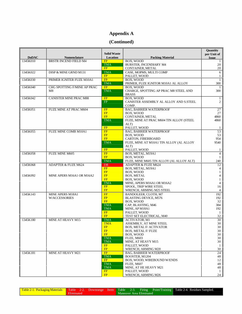
Table 2-1. Packaging Materials Table 2-2. Downrange ItemsEliminated
Table 2-3. Firing Point/TrainingManeuver Area Eliminated
Table 2-4. Residues Sampled.
Appendix A
(Continued)
DoDAC NomenclatureSolid Waste
Location Packing Material
Quantityper Unit of
Issue1345K010 BRSTR INCEND FIELD M4 FP BOX, WOOD 1
TMA BURSTER, INCENDIARY M4 20FP CONTAINER, METAL 20
1345K022 DISP & MINE GRND M131 TMA CASE, MOPMS, MULTI COMP 6FP PALLET, WOOD 1
1345K030 PRIMER IGNITER FUZE M10A1 FP BOX, WOOD 1TMA PRIMER, FUZE IGNITOR M10A1 AL ALLOY 300
1345K040 CHG SPOTTING F/MINE AP PRAC FP BOX, WOOD 1M8 TMA CHARGE, SPOTTING AP PRAC M8 STEEL AND
BRASS300
1345K042 CANISTER MINE PRAC M88 FP BOX, WOOD 1FP CANISTER ASSEMBLY AL ALLOY AND S.STEEL
COMP.2
1345K051 FUZE MINE AT PRAC M604 FP BAG, BARRIER WATERPROOF 27FP BOX, WOOD 27FP CONTAINER, METAL 4860TMA FUZE, MINE AT PRAC M604 TIN ALLOY (STEEL
ALT)4860
FP PALLET, WOOD 11345K055 FUZE MINE COMB M10A1 FP BAG, BARRIER WATERPROOF 53
FP BOX, WOOD 53FP CARTON, FIBERBOARD 954TMA FUZE, MINE AT M10A1 TIN ALLOY (AL ALLOY
ALT)9540
FP PALLET, WOOD 11345K058 FUZE MINE M605 FP BOX, METAL, M19A1 4
FP BOX, WOOD 1TMA FUZE, MINE M605 TIN ALLOY (AL ALLOY ALT) 240
1345K068 ADAPTER & FUZE M624 DR ADAPTER & FUZE M624 12FP BOX, METAL, M19A1 4FP BOX, WOOD 1
1345K092 MINE APERS M16A1 OR M16A2 FP BOX, METAL 4FP BOX, WOOD 1TMA MINE, APERS M16A1 OR M16A2 4FP SPOOL, TRIP WIRE STEEL 16FP WRENCH, ARMING M25 STEEL 4
1345K143 MINE APERS M18A1 FP BANDOLEER, CLOTH, M7 192W/ACCESSORIES FP BLASTING DEVICE, M576 192
FP BOX, WOOD 32TMA CAP, BLASTING, M46 384TMA MINE, AP M18A1 192FP PALLET, WOOD 1FP TEST SET ELECTRICAL, M40 32
1345K180 MINE AT HEAVY M15 TMA ACTIVATOR, M1 30TMA ASSEMBLY, AT MINE STEEL 30FP BOX, METAL F/ ACTIVATOR 30FP BOX, METAL F/ FUZE 30FP BOX, WOOD 30TMA FUZE, M603 30TMA MINE, AT HEAVY M15 30FP PALLET, WOOD 1FP WRENCH, ARMING M20 30
1345K181 MINE AT HEAVY M21 FP BAG, BARRIER WATERPROOF 24TMA BOOSTER, M1204 48FP BOX, WOOD, WIREBOUND W/ENDS 12TMA FUZE, M607 48TMA MINE, AT HE HEAVY M21 48FP PALLET, WOOD 1FP WRENCH, ARMING M26 24
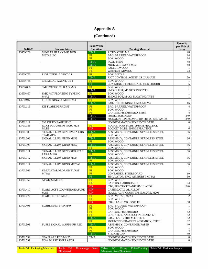
Table 2-1. Packaging Materials Table 2-2. Downrange ItemsEliminated
Table 2-3. Firing Point/TrainingManeuver Area Eliminated
Table 2-4. Residues Sampled.
Appendix A
(Continued)
DoDAC NomenclatureSolid Waste
Location Packing Material
Quantityper Unit of
Issue1345K250 MINE AT HEAVY M19 NON TMA ACTIVATOR, M2 48
METALLIC FP BAG, BARRIER WATERPROOF 24FP BOX, WOOD 24TMA FUZE, M606 48TMA MINE, AT HEAVY M19 48FP PALLET, WOOD 1FP WRENCH, ARMING 24
1365K765 RIOT CNTRL AGENT CS FP BOX, METAL 1TMA RIOT CONTROL AGENT, CS CAPSULE 50
1365K768 CHEMICAL AGENT, CS-1 FP BOX, WOOD 1FP CONTAINER, FIBERBOARD (8LB LIQUID) 5
1365K866 SMK POT HC 30LB ABC-M5 FP BOX, WOOD 1TMA SMOKE POT, M5 GROUND TYPE 1
1365K867 SMK POT FLOATING TYPE HC FP BOX, WOOD 1M4A2 TMA SMOKE POT, M4A2, FLOATING TYPE 1
1365K917 THICKENING COMPND M4 FP BOX, WOOD 1TMA PAIL, THICKENING COMPUND M4 16
1370L116 KIT FLARE PERS DIST FP BAG, BARRIER WATERPROOF 4FP BOX, WOOD 1FP CARTON, FIBERBOARD, M185 4TMA PROJECTOR, XM20 240TMA SIGNAL KIT, PERSONAL DISTRESS, RED XM185 840
1370L119 SIG KIT FOLIAGE PENE NO INFORMATION FOUND TO DATE 01370L185 RCKT POD 298MM PRAC M28 FP ROCKET POD, MLRS, 298MM PRACTICE 1
MLRS DR ROCKET, MLRS, 298MM PRACTICE 61370L305 SIGNAL ILLUM GRND PARA GRN TMA ASSEMBLY, CONTAINER STAINLESS STEEL 36
STAR M195 FP BOX, WOOD 11370L306 SIGNAL ILLUM GRND M158 TMA ASSEMBLY, CONTAINER STAINLESS STEEL 36
FP BOX, WOOD 11370L307 SIGNAL ILLUM GRND M159 TMA ASSEMBLY, CONTAINER STAINLESS STEEL 36
FP BOX, WOOD 11370L311 SIGNAL ILLUM GRND RED STAR TMA ASSEMBLY, CONTAINER STAINLESS STEEL 36
PARA M126 FP BOX, WOOD 11370L312 SIGNAL ILLUM GRND M127 TMA ASSEMBLY, CONTAINER STAINLESS STEEL 36
FP BOX, WOOD 11370L314 SIGNAL ILLUM GRND M125A1 TMA ASSEMBLY, CONTAINER STAINLESS STEEL 36
FP BOX, WOOD 11370L366 SIMULATOR PROJ AIR BURST FP BOX, WOOD 1
M74A1 FP CONTAINER, FIBERBOARD 10FP SIMULATOR, PROJ AIR BURST M74A1 80
1370L367 ATWESS (MILES) FP BOX, WOOD 1FP CARTON, CARDBOARD 24DR CTG, PRACTICE TANK SIMULATOR 240
1370L410 FLARE ACFT COUNTERMEASURE DR CASING, CTG, AL ALLOY 1M206 DR FLARE, ACFT COUNTERMEASURE, M206 1
1370L477 FLARE, IR TRK MK33 FP BOX, METAL, M2A1 2FP BOX, WOOD 1DR CTG, FLARE MK 33 STEEL 50
1370L495 FLARE SURF TRIP M49 FP BAG, BARRIER WATERPROOF 1FP BOX, WOOD 1FP CARTON, FIBERBOARD 32FP COIL STEEL AND ROOFING NAILS (2) 32TMA CTG, FLARE, TRIP M49 STEEL 32FP MOUNTING BRACKET ASSEMBLY, STEEL 32
1370L508 FUSEE SIGNAL WARNS RR RED TMA ASSEMBLY, CONTAINER PAPER 40FP BOX, WOOD 1FP CARTON, FIBERBOARD 4TMA STRIKER CAP 40
1370L554 SEA FLARE RED MK25 TMA NO INFORMATION FOUND TO DATE 01370L592 TOW BLAST SIMULATOR NO INFORMATION FOUND TO DATE 0
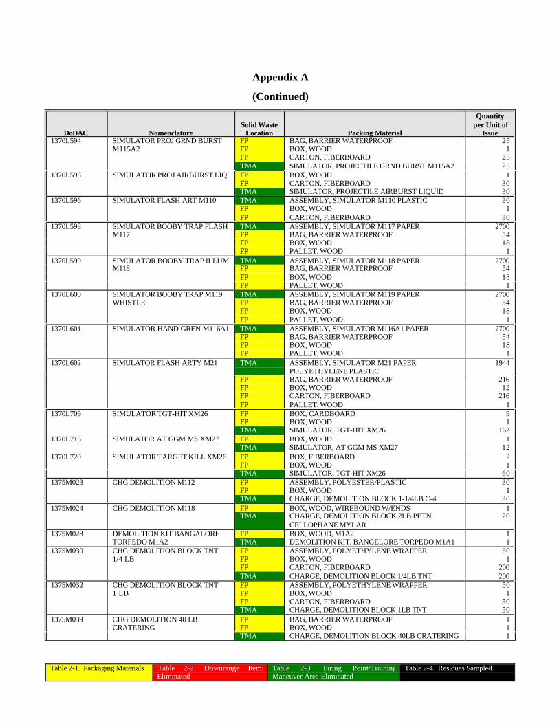
Table 2-1. Packaging Materials Table 2-2. Downrange ItemsEliminated
Table 2-3. Firing Point/TrainingManeuver Area Eliminated
Table 2-4. Residues Sampled.
Appendix A
(Continued)
DoDAC NomenclatureSolid Waste
Location Packing Material
Quantityper Unit of
Issue1370L594 SIMULATOR PROJ GRND BURST FP BAG, BARRIER WATERPROOF 25
M115A2 FP BOX, WOOD 1FP CARTON, FIBERBOARD 25TMA SIMULATOR, PROJECTILE GRND BURST M115A2 25
1370L595 SIMULATOR PROJ AIRBURST LIQ FP BOX, WOOD 1FP CARTON, FIBERBOARD 30TMA SIMULATOR, PROJECTILE AIRBURST LIQUID 30
1370L596 SIMULATOR FLASH ART M110 TMA ASSEMBLY, SIMULATOR M110 PLASTIC 30FP BOX, WOOD 1FP CARTON, FIBERBOARD 30
1370L598 SIMULATOR BOOBY TRAP FLASH TMA ASSEMBLY, SIMULATOR M117 PAPER 2700M117 FP BAG, BARRIER WATERPROOF 54
FP BOX, WOOD 18FP PALLET, WOOD 1
1370L599 SIMULATOR BOOBY TRAP ILLUM TMA ASSEMBLY, SIMULATOR M118 PAPER 2700M118 FP BAG, BARRIER WATERPROOF 54
FP BOX, WOOD 18FP PALLET, WOOD 1
1370L600 SIMULATOR BOOBY TRAP M119 TMA ASSEMBLY, SIMULATOR M119 PAPER 2700WHISTLE FP BAG, BARRIER WATERPROOF 54
FP BOX, WOOD 18FP PALLET, WOOD 1
1370L601 SIMULATOR HAND GREN M116A1 TMA ASSEMBLY, SIMULATOR M116A1 PAPER 2700FP BAG, BARRIER WATERPROOF 54FP BOX, WOOD 18FP PALLET, WOOD 1
1370L602 SIMULATOR FLASH ARTY M21 TMA ASSEMBLY, SIMULATOR M21 PAPERPOLYETHYLENE PLASTIC
1944
FP BAG, BARRIER WATERPROOF 216FP BOX, WOOD 12FP CARTON, FIBERBOARD 216FP PALLET, WOOD 1
1370L709 SIMULATOR TGT-HIT XM26 FP BOX, CARDBOARD 9FP BOX, WOOD 1TMA SIMULATOR, TGT-HIT XM26 162
1370L715 SIMULATOR AT GGM MS XM27 FP BOX, WOOD 1TMA SIMULATOR, AT GGM MS XM27 12
1370L720 SIMULATOR TARGET KILL XM26 FP BOX, FIBERBOARD 2FP BOX, WOOD 1TMA SIMULATOR, TGT-HIT XM26 60
1375M023 CHG DEMOLITION M112 FP ASSEMBLY, POLYESTER/PLASTIC 30FP BOX, WOOD 1TMA CHARGE, DEMOLITION BLOCK 1-1/4LB C-4 30
1375M024 CHG DEMOLITION M118 FP BOX, WOOD, WIREBOUND W/ENDS 1TMA CHARGE, DEMOLITION BLOCK 2LB PETN
CELLOPHANE MYLAR20
1375M028 DEMOLITION KIT BANGALORE FP BOX, WOOD, M1A2 1TORPEDO M1A2 TMA DEMOLITION KIT, BANGELORE TORPEDO M1A1 1
1375M030 CHG DEMOLITION BLOCK TNT FP ASSEMBLY, POLYETHYLENE WRAPPER 501/4 LB FP BOX, WOOD 1
FP CARTON, FIBERBOARD 200TMA CHARGE, DEMOLITION BLOCK 1/4LB TNT 200
1375M032 CHG DEMOLITION BLOCK TNT FP ASSEMBLY, POLYETHYLENE WRAPPER 501 LB FP BOX, WOOD 1
FP CARTON, FIBERBOARD 50TMA CHARGE, DEMOLITION BLOCK 1LB TNT 50
1375M039 CHG DEMOLITION 40 LB FP BAG, BARRIER WATERPROOF 1CRATERING FP BOX, WOOD 1
TMA CHARGE, DEMOLITION BLOCK 40LB CRATERING 1
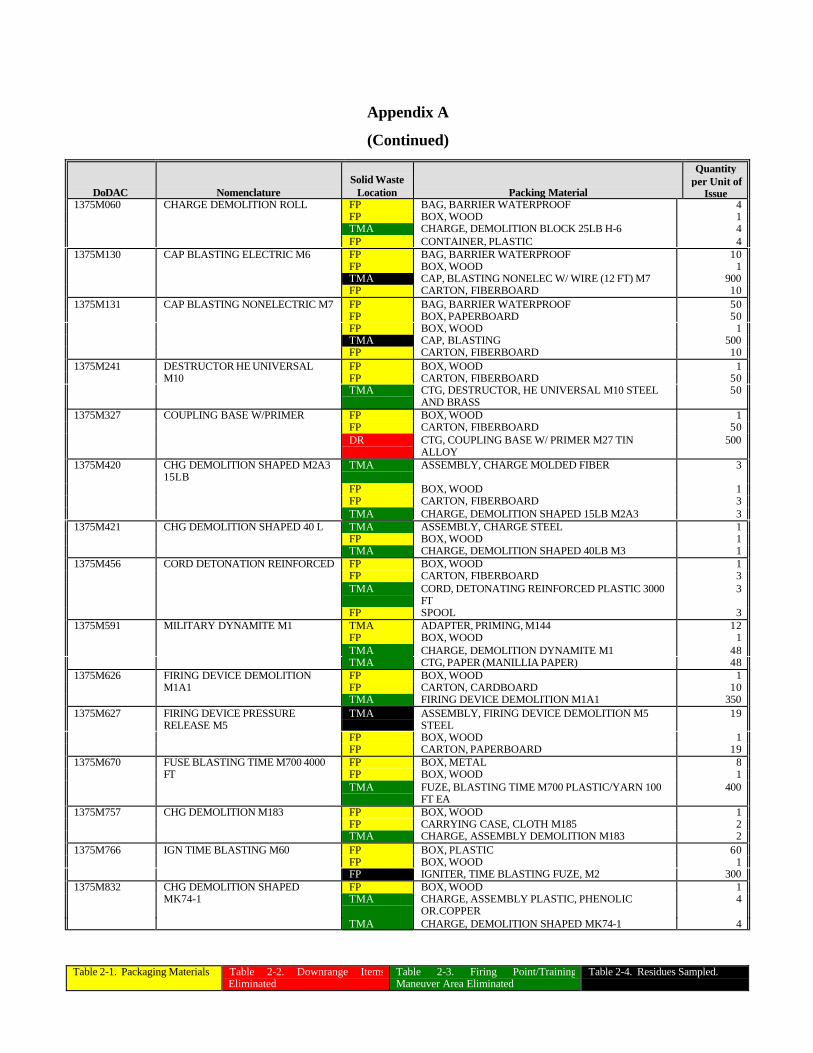
Table 2-1. Packaging Materials Table 2-2. Downrange ItemsEliminated
Table 2-3. Firing Point/TrainingManeuver Area Eliminated
Table 2-4. Residues Sampled.
Appendix A
(Continued)
DoDAC NomenclatureSolid Waste
Location Packing Material
Quantityper Unit of
Issue1375M060 CHARGE DEMOLITION ROLL FP BAG, BARRIER WATERPROOF 4
FP BOX, WOOD 1TMA CHARGE, DEMOLITION BLOCK 25LB H-6 4FP CONTAINER, PLASTIC 4
1375M130 CAP BLASTING ELECTRIC M6 FP BAG, BARRIER WATERPROOF 10FP BOX, WOOD 1TMA CAP, BLASTING NONELEC W/ WIRE (12 FT) M7 900FP CARTON, FIBERBOARD 10
1375M131 CAP BLASTING NONELECTRIC M7 FP BAG, BARRIER WATERPROOF 50FP BOX, PAPERBOARD 50FP BOX, WOOD 1TMA CAP, BLASTING 500FP CARTON, FIBERBOARD 10
1375M241 DESTRUCTOR HE UNIVERSAL FP BOX, WOOD 1M10 FP CARTON, FIBERBOARD 50
TMA CTG, DESTRUCTOR, HE UNIVERSAL M10 STEELAND BRASS
50
1375M327 COUPLING BASE W/PRIMER FP BOX, WOOD 1FP CARTON, FIBERBOARD 50DR CTG, COUPLING BASE W/ PRIMER M27 TIN
ALLOY500
1375M420 CHG DEMOLITION SHAPED M2A315LB
TMA ASSEMBLY, CHARGE MOLDED FIBER 3
FP BOX, WOOD 1FP CARTON, FIBERBOARD 3TMA CHARGE, DEMOLITION SHAPED 15LB M2A3 3
1375M421 CHG DEMOLITION SHAPED 40 L TMA ASSEMBLY, CHARGE STEEL 1FP BOX, WOOD 1TMA CHARGE, DEMOLITION SHAPED 40LB M3 1
1375M456 CORD DETONATION REINFORCED FP BOX, WOOD 1FP CARTON, FIBERBOARD 3TMA CORD, DETONATING REINFORCED PLASTIC 3000
FT3
FP SPOOL 31375M591 MILITARY DYNAMITE M1 TMA ADAPTER, PRIMING, M144 12
FP BOX, WOOD 1TMA CHARGE, DEMOLITION DYNAMITE M1 48TMA CTG, PAPER (MANILLIA PAPER) 48
1375M626 FIRING DEVICE DEMOLITION FP BOX, WOOD 1M1A1 FP CARTON, CARDBOARD 10
TMA FIRING DEVICE DEMOLITION M1A1 3501375M627 FIRING DEVICE PRESSURE
RELEASE M5TMA ASSEMBLY, FIRING DEVICE DEMOLITION M5
STEEL19
FP BOX, WOOD 1FP CARTON, PAPERBOARD 19
1375M670 FUSE BLASTING TIME M700 4000 FP BOX, METAL 8FT FP BOX, WOOD 1
TMA FUZE, BLASTING TIME M700 PLASTIC/YARN 100FT EA
400
1375M757 CHG DEMOLITION M183 FP BOX, WOOD 1FP CARRYING CASE, CLOTH M185 2TMA CHARGE, ASSEMBLY DEMOLITION M183 2
1375M766 IGN TIME BLASTING M60 FP BOX, PLASTIC 60FP BOX, WOOD 1FP IGNITER, TIME BLASTING FUZE, M2 300
1375M832 CHG DEMOLITION SHAPED FP BOX, WOOD 1MK74-1 TMA CHARGE, ASSEMBLY PLASTIC, PHENOLIC
OR.COPPER4
TMA CHARGE, DEMOLITION SHAPED MK74-1 4
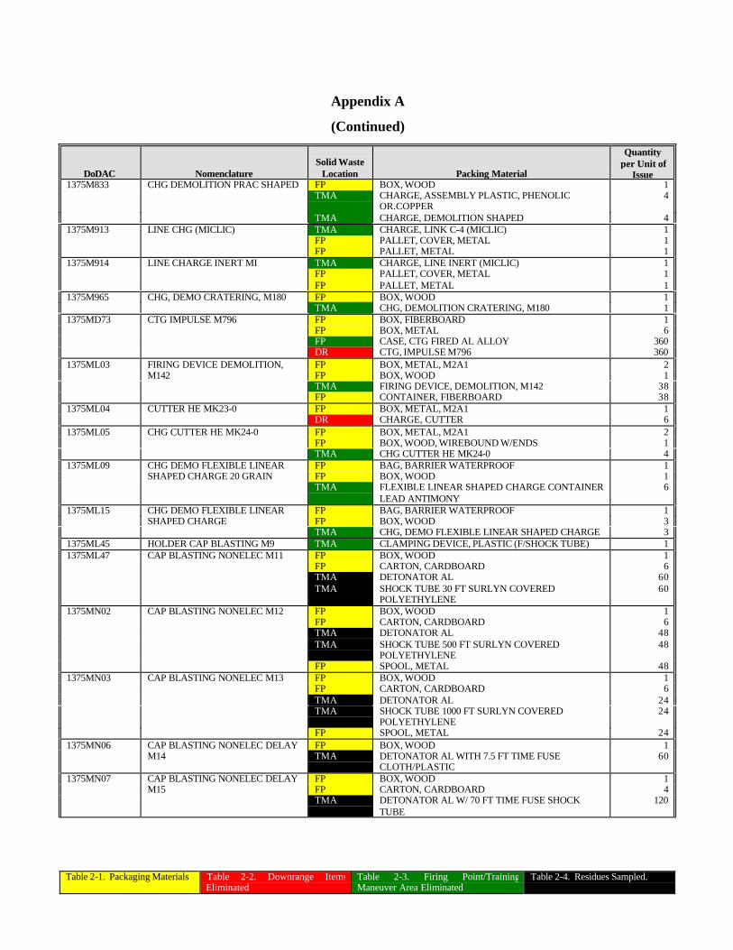
Table 2-1. Packaging Materials Table 2-2. Downrange ItemsEliminated
Table 2-3. Firing Point/TrainingManeuver Area Eliminated
Table 2-4. Residues Sampled.
Appendix A
(Continued)
DoDAC NomenclatureSolid Waste
Location Packing Material
Quantityper Unit of
Issue1375M833 CHG DEMOLITION PRAC SHAPED FP BOX, WOOD 1
TMA CHARGE, ASSEMBLY PLASTIC, PHENOLICOR.COPPER
4
TMA CHARGE, DEMOLITION SHAPED 41375M913 LINE CHG (MICLIC) TMA CHARGE, LINK C-4 (MICLIC) 1
FP PALLET, COVER, METAL 1FP PALLET, METAL 1
1375M914 LINE CHARGE INERT MI TMA CHARGE, LINE INERT (MICLIC) 1FP PALLET, COVER, METAL 1FP PALLET, METAL 1
1375M965 CHG, DEMO CRATERING, M180 FP BOX, WOOD 1TMA CHG, DEMOLITION CRATERING, M180 1
1375MD73 CTG IMPULSE M796 FP BOX, FIBERBOARD 1FP BOX, METAL 6FP CASE, CTG FIRED AL ALLOY 360DR CTG, IMPULSE M796 360
1375ML03 FIRING DEVICE DEMOLITION, FP BOX, METAL, M2A1 2M142 FP BOX, WOOD 1
TMA FIRING DEVICE, DEMOLITION, M142 38FP CONTAINER, FIBERBOARD 38
1375ML04 CUTTER HE MK23-0 FP BOX, METAL, M2A1 1DR CHARGE, CUTTER 6
1375ML05 CHG CUTTER HE MK24-0 FP BOX, METAL, M2A1 2FP BOX, WOOD, WIREBOUND W/ENDS 1TMA CHG CUTTER HE MK24-0 4
1375ML09 CHG DEMO FLEXIBLE LINEAR FP BAG, BARRIER WATERPROOF 1SHAPED CHARGE 20 GRAIN FP BOX, WOOD 1
TMA FLEXIBLE LINEAR SHAPED CHARGE CONTAINERLEAD ANTIMONY
6
1375ML15 CHG DEMO FLEXIBLE LINEAR FP BAG, BARRIER WATERPROOF 1SHAPED CHARGE FP BOX, WOOD 3
TMA CHG, DEMO FLEXIBLE LINEAR SHAPED CHARGE 31375ML45 HOLDER CAP BLASTING M9 TMA CLAMPING DEVICE, PLASTIC (F/SHOCK TUBE) 11375ML47 CAP BLASTING NONELEC M11 FP BOX, WOOD 1
FP CARTON, CARDBOARD 6TMA DETONATOR AL 60TMA SHOCK TUBE 30 FT SURLYN COVERED
POLYETHYLENE60
1375MN02 CAP BLASTING NONELEC M12 FP BOX, WOOD 1FP CARTON, CARDBOARD 6TMA DETONATOR AL 48TMA SHOCK TUBE 500 FT SURLYN COVERED
POLYETHYLENE48
FP SPOOL, METAL 481375MN03 CAP BLASTING NONELEC M13 FP BOX, WOOD 1
FP CARTON, CARDBOARD 6TMA DETONATOR AL 24TMA SHOCK TUBE 1000 FT SURLYN COVERED
POLYETHYLENE24
FP SPOOL, METAL 241375MN06 CAP BLASTING NONELEC DELAY FP BOX, WOOD 1
M14 TMA DETONATOR AL WITH 7.5 FT TIME FUSECLOTH/PLASTIC
60
1375MN07 CAP BLASTING NONELEC DELAY FP BOX, WOOD 1M15 FP CARTON, CARDBOARD 4
TMA DETONATOR AL W/ 70 FT TIME FUSE SHOCKTUBE
120
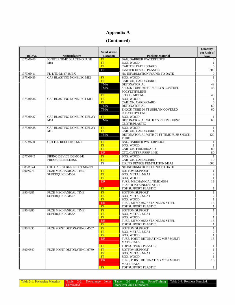
Table 2-1. Packaging Materials Table 2-2. Downrange ItemsEliminated
Table 2-3. Firing Point/TrainingManeuver Area Eliminated
Table 2-4. Residues Sampled.
Appendix A
(Continued)
DoDAC NomenclatureSolid Waste
Location Packing Material
Quantityper Unit of
Issue1375MN08 IGNITER TIME BLASTING FUSE FP BAG, BARRIER WATERPROOF 6
M81 FP BOX, WOOD 1FP CARTON, PAPERBOARD 6FP IGNITER DEVICE PLASTIC 300
1375MN11 FD DTD M147 48/BX NO INFORMATION FOUND TO DATE 01375MN35 CAP BLASTING NONELEC M12 FP BOX, WOOD 1
FP CARTON, CARDBOARD 6TMA DETONATOR AL 48TMA SHOCK TUBE 500 FT SURLYN COVERED
POLYETHYLENE48
FP SPOOL, METAL 481375MN36 CAP BLASTING NONELECT M11 FP BOX, WOOD 1
FP CARTON, CARDBOARD 6TMA DETONATOR AL 60TMA SHOCK TUBE 30 FT SURLYN COVERED
POLYETHYLENE60
1375MN37 CAP BLASTING NONELEC DELAY FP BOX, WOOD 1M14 TMA DETONATOR AL WITH 7.5 FT TIME FUSE
CLOTH/PLASTIC60
1375MN38 CAP BLASTING NONELEC DELAY FP BOX, WOOD 1M15 FP CARTON, CARDBOARD 4
TMA DETONATOR AL WITH 70 FT TIME FUSE SHOCKTUBE
120
1377M500 CUTTER REEF LINE M21 FP BAG, BARRIER WATERPROOF 1FP BOX, WOOD 1FP CARTON, FIBERBOARD 80DR CTG, CUTTER REEF LINE 80
1377M842 FIRING DEVICE DEMO M1 FP BOX, WOOD 1PRESSURE RELEASE FP CARTON, CARDBOARD 10
FP FIRING DEVICE DEMOLITION M1A1 5001385M174 CTG CAL .50 BLK ELECT MK209 NO INFORMATION FOUND TO DATE 01390N278 FUZE MECHANICAL TIME FP BOTTOM SUPPORT 1
SUPERQUICK M564 FP BOX, METAL, M2A1 2FP BOX, WOOD 1DR FUZE, MECHANICAL TIME M564
PLASTIC/STAINLESS STEEL16
FP TOP SUPPORT PLASTIC 11390N285 FUZE MECHANICAL TIME FP BOTTOM SUPPORT 1
SUPERQUICK M577 FP BOX, METAL, M2A1 2FP BOX, WOOD 1DR FUZE, MTSQ M577 STAINLESS STEEL 16FP TOP SUPPORT PLASTIC 1
1390N286 FUZE MECHANICAL TIME FP BOTTOM SUPPORT 1SUPERQUICK M582 FP BOX, METAL, M2A1 2
FP BOX, WOOD 1DR FUZE, MTSO M582 STAINLESS STEEL 16FP TOP SUPPORT PLASTIC 1
1390N335 FUZE POINT DETONATING M557 FP BOTTOM SUPPORT 1FP BOX, METAL, M2A1 2FP BOX, WOOD 1DR FUZE, POINT DETONATING M557 MULTI
MATERIALS16
FP TOP SUPPORT PLASTIC 11390N340 FUZE POINT DETONATING M739 FP BOTTOM SUPPORT 1
FP BOX, METAL, M2A1 2FP BOX, WOOD 1DR FUZE, POINT DETONATING M739 MULTI
MATERIALS16
FP TOP SUPPORT PLASTIC 1
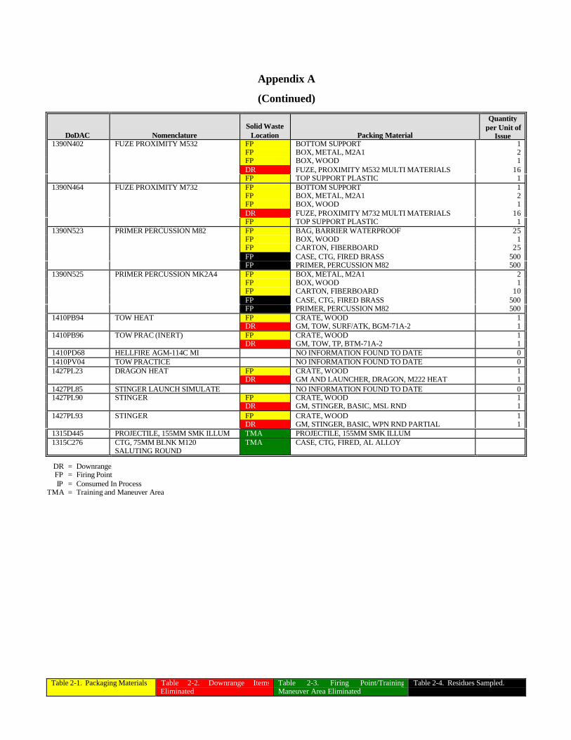
Table 2-1. Packaging Materials Table 2-2. Downrange ItemsEliminated
Table 2-3. Firing Point/TrainingManeuver Area Eliminated
Table 2-4. Residues Sampled.
Appendix A
(Continued)
DoDAC NomenclatureSolid Waste
Location Packing Material
Quantityper Unit of
Issue1390N402 FUZE PROXIMITY M532 FP BOTTOM SUPPORT 1
FP BOX, METAL, M2A1 2FP BOX, WOOD 1DR FUZE, PROXIMITY M532 MULTI MATERIALS 16FP TOP SUPPORT PLASTIC 1
1390N464 FUZE PROXIMITY M732 FP BOTTOM SUPPORT 1FP BOX, METAL, M2A1 2FP BOX, WOOD 1DR FUZE, PROXIMITY M732 MULTI MATERIALS 16FP TOP SUPPORT PLASTIC 1
1390N523 PRIMER PERCUSSION M82 FP BAG, BARRIER WATERPROOF 25FP BOX, WOOD 1FP CARTON, FIBERBOARD 25FP CASE, CTG, FIRED BRASS 500FP PRIMER, PERCUSSION M82 500
1390N525 PRIMER PERCUSSION MK2A4 FP BOX, METAL, M2A1 2FP BOX, WOOD 1FP CARTON, FIBERBOARD 10FP CASE, CTG, FIRED BRASS 500FP PRIMER, PERCUSSION M82 500
1410PB94 TOW HEAT FP CRATE, WOOD 1DR GM, TOW, SURF/ATK, BGM-71A-2 1
1410PB96 TOW PRAC (INERT) FP CRATE, WOOD 1DR GM, TOW, TP, BTM-71A-2 1
1410PD68 HELLFIRE AGM-114C MI NO INFORMATION FOUND TO DATE 01410PV04 TOW PRACTICE NO INFORMATION FOUND TO DATE 01427PL23 DRAGON HEAT FP CRATE, WOOD 1
DR GM AND LAUNCHER, DRAGON, M222 HEAT 11427PL85 STINGER LAUNCH SIMULATE NO INFORMATION FOUND TO DATE 01427PL90 STINGER FP CRATE, WOOD 1
DR GM, STINGER, BASIC, MSL RND 11427PL93 STINGER FP CRATE, WOOD 1
DR GM, STINGER, BASIC, WPN RND PARTIAL 11315D445 PROJECTILE, 155MM SMK ILLUM TMA PROJECTILE, 155MM SMK ILLUM1315C276 CTG, 75MM BLNK M120
SALUTING ROUNDTMA CASE, CTG, FIRED, AL ALLOY
DR = DownrangeFP = Firing PointIP = Consumed In Process
TMA = Training and Maneuver Area
Appendix B
SAMPLE COLLECTION RECORD
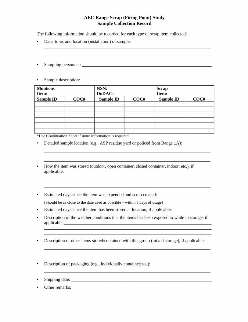
AEC Range Scrap (Firing Point) StudySample Collection Record
The following information should be recorded for each type of scrap item collected:
• Date, time, and location (installation) of sample:
• Sampling personnel: __________________________________________________________
___________________________________________________________________________
• Sample description:
MuntionsItem:
NSN:DoDAC:
ScrapItem:
Sample ID COC# Sample ID COC# Sample ID COC#
*Use Continuation Sheet if more information is required.
• Detailed sample location (e.g., ASP residue yard or policed from Range 1A):
• How the item was stored (outdoor, open container, closed container, indoor, etc.), ifapplicable:
• Estimated days since the item was expended and scrap created:
(Should be as close to the date used as possible – within 5 days of usage)
• Estimated days since the item has been stored at location, if applicable:
• Description of the weather conditions that the items has been exposed to while in storage, ifapplicable:________________________________________________________________________________________________________________________________________________________________________________________________________________________
• Description of other items stored/contained with this group (mixed storage), if applicable:
• Description of packaging (e.g., individually containerized):
• Shipping date: _______________________________________________________________
• Other remarks:

Appendix C
SOLID FLUX ANALYSIS
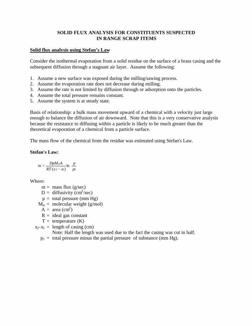
SOLID FLUX ANALYSIS FOR CONSTITUENTS SUSPECTEDIN RANGE SCRAP ITEMS
Solid flux analysis using Stefan’s Law
Consider the isothermal evaporation from a solid residue on the surface of a brass casing and thesubsequent diffusion through a stagnant air layer. Assume the following:
1. Assume a new surface was exposed during the milling/sawing process.2. Assume the evaporation rate does not decrease during milling.3. Assume the rate is not limited by diffusion through or adsorption onto the particles.4. Assume the total pressure remains constant.5. Assume the system is at steady state.
Basis of relationship: a bulk mass movement upward of a chemical with a velocity just largeenough to balance the diffusion of air downward. Note that this is a very conservative analysisbecause the resistance to diffusing within a particle is likely to be much greater than thetheoretical evaporation of a chemical from a particle surface.
The mass flow of the chemical from the residue was estimated using Stefan's Law.
Stefan's Law:
Where:m = mass flux (g/sec)D = diffusivity (cm2/sec)p = total pressure (mm Hg)
Mw = molecular weight (g/mol)A = area (cm2)R = ideal gas constantT = temperature (K)
x2-x1 = length of casing (cm)Note: Half the length was used due to the fact the casing was cut in half.
p1 = total pressure minus the partial pressure of substance (mm Hg).
−
=112
ln)( p
pxxRT
ADpMm w
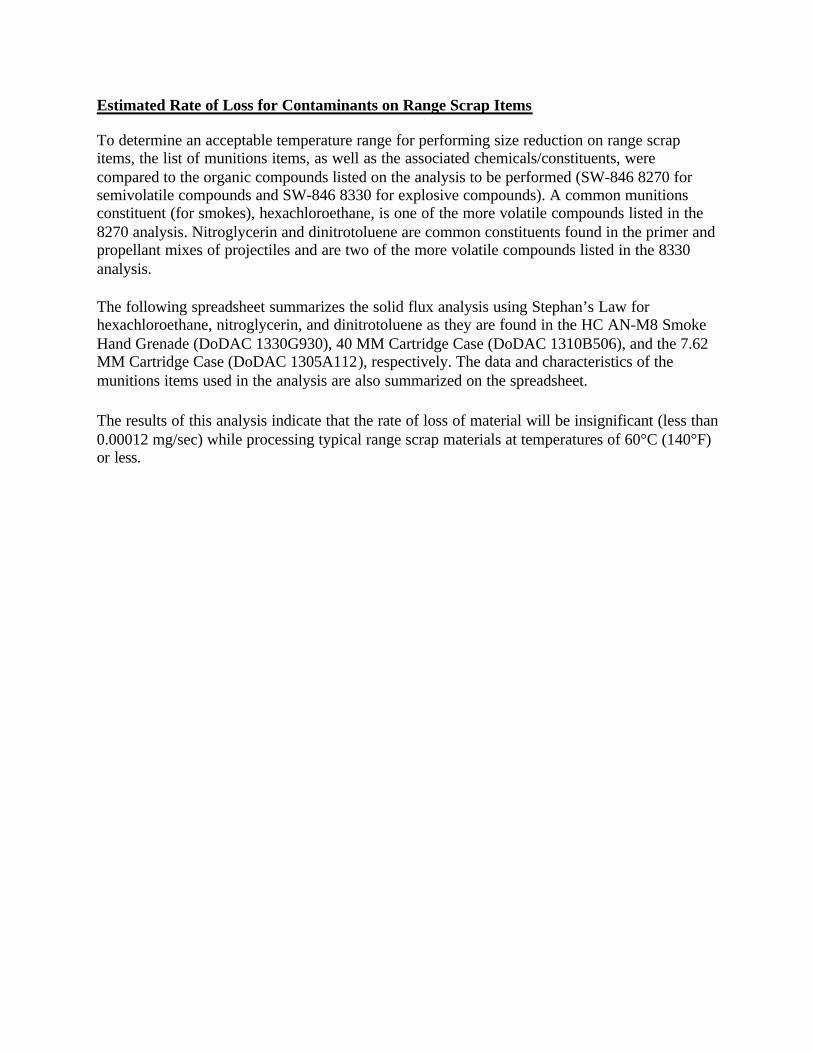
Estimated Rate of Loss for Contaminants on Range Scrap Items
To determine an acceptable temperature range for performing size reduction on range scrapitems, the list of munitions items, as well as the associated chemicals/constituents, werecompared to the organic compounds listed on the analysis to be performed (SW-846 8270 forsemivolatile compounds and SW-846 8330 for explosive compounds). A common munitionsconstituent (for smokes), hexachloroethane, is one of the more volatile compounds listed in the8270 analysis. Nitroglycerin and dinitrotoluene are common constituents found in the primer andpropellant mixes of projectiles and are two of the more volatile compounds listed in the 8330analysis.
The following spreadsheet summarizes the solid flux analysis using Stephan’s Law forhexachloroethane, nitroglycerin, and dinitrotoluene as they are found in the HC AN-M8 SmokeHand Grenade (DoDAC 1330G930), 40 MM Cartridge Case (DoDAC 1310B506), and the 7.62MM Cartridge Case (DoDAC 1305A112), respectively. The data and characteristics of themunitions items used in the analysis are also summarized on the spreadsheet.
The results of this analysis indicate that the rate of loss of material will be insignificant (less than0.00012 mg/sec) while processing typical range scrap materials at temperatures of 60°C (140°F)or less.
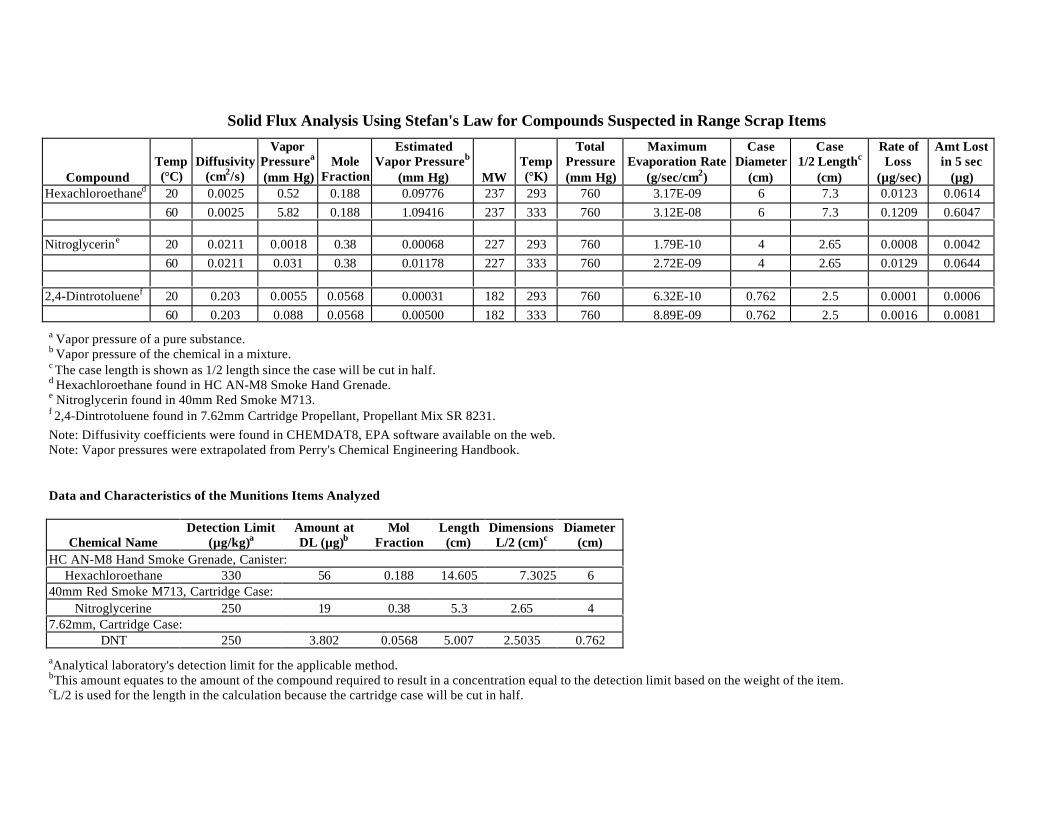
Solid Flux Analysis Using Stefan's Law for Compounds Suspected in Range Scrap Items
CompoundTemp(°C)
Diffusivity(cm2/s)
VaporPressurea
(mm Hg)Mole
Fraction
EstimatedVapor Pressureb
(mm Hg) MWTemp(°K)
TotalPressure(mm Hg)
MaximumEvaporation Rate
(g/sec/cm2)
CaseDiameter
(cm)
Case1/2 Lengthc
(cm)
Rate ofLoss
(µg/sec)
Amt Lostin 5 sec
(µg)Hexachloroethaned 20 0.0025 0.52 0.188 0.09776 237 293 760 3.17E-09 6 7.3 0.0123 0.0614
60 0.0025 5.82 0.188 1.09416 237 333 760 3.12E-08 6 7.3 0.1209 0.6047
Nitroglycerine 20 0.0211 0.0018 0.38 0.00068 227 293 760 1.79E-10 4 2.65 0.0008 0.004260 0.0211 0.031 0.38 0.01178 227 333 760 2.72E-09 4 2.65 0.0129 0.0644
2,4-Dintrotoluenef 20 0.203 0.0055 0.0568 0.00031 182 293 760 6.32E-10 0.762 2.5 0.0001 0.000660 0.203 0.088 0.0568 0.00500 182 333 760 8.89E-09 0.762 2.5 0.0016 0.0081
a Vapor pressure of a pure substance.b Vapor pressure of the chemical in a mixture.c The case length is shown as 1/2 length since the case will be cut in half.d Hexachloroethane found in HC AN-M8 Smoke Hand Grenade.e Nitroglycerin found in 40mm Red Smoke M713.f 2,4-Dintrotoluene found in 7.62mm Cartridge Propellant, Propellant Mix SR 8231.Note: Diffusivity coefficients were found in CHEMDAT8, EPA software available on the web.Note: Vapor pressures were extrapolated from Perry's Chemical Engineering Handbook.
Data and Characteristics of the Munitions Items Analyzed
Chemical NameDetection Limit
(µg/kg)aAmount atDL (µg)b
MolFraction
Length(cm)
DimensionsL/2 (cm)c
Diameter(cm)
HC AN-M8 Hand Smoke Grenade, Canister:Hexachloroethane 330 56 0.188 14.605 7.3025 6
40mm Red Smoke M713, Cartridge Case:Nitroglycerine 250 19 0.38 5.3 2.65 4
7.62mm, Cartridge Case:DNT 250 3.802 0.0568 5.007 2.5035 0.762
aAnalytical laboratory's detection limit for the applicable method.bThis amount equates to the amount of the compound required to result in a concentration equal to the detection limit based on the weight of the item.cL/2 is used for the length in the calculation because the cartridge case will be cut in half.
Appendix D
SAMPLE PREPARATION RECORD
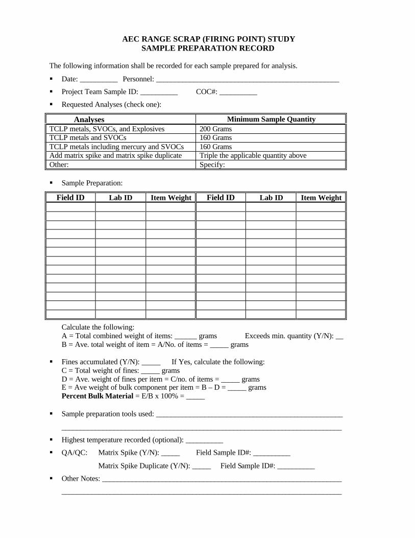
AEC RANGE SCRAP (FIRING POINT) STUDYSAMPLE PREPARATION RECORD
The following information shall be recorded for each sample prepared for analysis.
§ Date: __________ Personnel: _________________________________________________
§ Project Team Sample ID: __________ COC#: __________
§ Requested Analyses (check one):
Analyses Minimum Sample QuantityTCLP metals, SVOCs, and Explosives 200 GramsTCLP metals and SVOCs 160 GramsTCLP metals including mercury and SVOCs 160 GramsAdd matrix spike and matrix spike duplicate Triple the applicable quantity aboveOther: Specify:
§ Sample Preparation:
Field ID Lab ID Item Weight Field ID Lab ID Item Weight
Calculate the following:A = Total combined weight of items: ______ grams Exceeds min. quantity (Y/N): __B = Ave. total weight of item = A/No. of items = _____ grams
§ Fines accumulated (Y/N): _____ If Yes, calculate the following:C = Total weight of fines: _____ gramsD = Ave. weight of fines per item = C/no. of items = _____ gramsE = Ave weight of bulk component per item = B – D = _____ gramsPercent Bulk Material = E/B x 100% = _____
§ Sample preparation tools used: __________________________________________________
___________________________________________________________________________
§ Highest temperature recorded (optional): __________
§ QA/QC: Matrix Spike (Y/N): _____ Field Sample ID#: __________
Matrix Spike Duplicate (Y/N): _____ Field Sample ID#: __________
§ Other Notes: ________________________________________________________________
___________________________________________________________________________
Appendix E
EXAMPLE STATEMENT OF WORK FOR SAMPLING AND ANALYSIS
Appendix E-1
GENERAL SAMPLE COLLECTION PROCEDURES
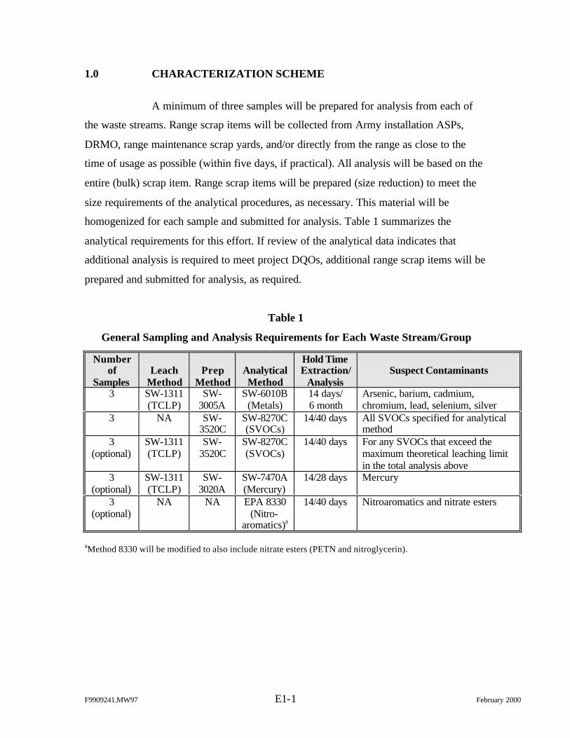
F9909241.MW97 E1-1 February 2000
1.0 CHARACTERIZATION SCHEME
A minimum of three samples will be prepared for analysis from each of
the waste streams. Range scrap items will be collected from Army installation ASPs,
DRMO, range maintenance scrap yards, and/or directly from the range as close to the
time of usage as possible (within five days, if practical). All analysis will be based on the
entire (bulk) scrap item. Range scrap items will be prepared (size reduction) to meet the
size requirements of the analytical procedures, as necessary. This material will be
homogenized for each sample and submitted for analysis. Table 1 summarizes the
analytical requirements for this effort. If review of the analytical data indicates that
additional analysis is required to meet project DQOs, additional range scrap items will be
prepared and submitted for analysis, as required.
Table 1
General Sampling and Analysis Requirements for Each Waste Stream/Group
Numberof
SamplesLeach
MethodPrep
MethodAnalyticalMethod
Hold TimeExtraction/
AnalysisSuspect Contaminants
3 SW-1311(TCLP)
SW-3005A
SW-6010B(Metals)
14 days/6 month
Arsenic, barium, cadmium,chromium, lead, selenium, silver
3 NA SW-3520C
SW-8270C(SVOCs)
14/40 days All SVOCs specified for analyticalmethod
3(optional)
SW-1311(TCLP)
SW-3520C
SW-8270C(SVOCs)
14/40 days For any SVOCs that exceed themaximum theoretical leaching limitin the total analysis above
3(optional)
SW-1311(TCLP)
SW-3020A
SW-7470A(Mercury)
14/28 days Mercury
3(optional)
NA NA EPA 8330(Nitro-
aromatics)a
14/40 days Nitroaromatics and nitrate esters
aMethod 8330 will be modified to also include nitrate esters (PETN and nitroglycerin).
F9909241.MW97 E1-2 February 2000
2.0 SAMPLE COLLECTION PROCEDURES
The sample collection procedures presented in this section apply to
collection of range scrap items to be submitted for sample preparation (size reduction) by
a subcontract laboratory or the project team.
2.1 Sample Collection
2.1.1 Sample collection performed by the project team
Range scrap items targeted for sampling may be collected from various
Army installations across the country based on the availability of the item. Range scrap
items stored at the ASP, DRMO, or other residue yard may be accumulated over various
periods of time. In lieu of designing an extensive sampling approach that would account
for the variability of item storage, this sampling effort will attempt to collect residues as
close to the time of usage as possible. This approach will ensure that characterization of
the range scrap items is consistent and the most conservative scenario.
The range scrap items will be collected, processed, and analyzed in an
effort to meet the holding time requirements listed in Table 1. Range scrap items will be
collected within 5 days from the date of usage to ensure the minimum holding time
requirement (14 days) is met. Variances from the holding time requirements may be
granted for items that are difficult to obtain due to the infrequency of use and will be
evaluated on a case by case basis. After collecting the range scrap items, the project team
will proceed to follow the requirements stated in Sections 2.2 through 2.8.
2.1.2 Sample collection performed by others
Sample collection may also be performed by other organizations and
provided to the project team for characterization. The project team will coordinate with
the other organization to prepare a listing of the range scrap items to be collected for
F9909241.MW97 E1-3 February 2000
characterization and the required quantities. The other organization must collect the range
scrap items in a timely manner as stated in Section 2.1.1. The range scrap items shall be
collected and shipped to the project team within 5 days of the date of usage. The
sampling procedure is outlined below:
1. Don a new pair of disposable gloves (avoid contacting samples withsynthetic materials, which could be a source of SVOC contamination)between each type of range scrap collected.
2. Obtain/collect the range scrap items (specific items and quantitiescoordinated with the project team) as close to the date of usage aspossible (refer to Section 2.1.1).
3. Perform “inert certification” (responsible organization) and retain acopy of the certification to accompany the samples.
4. Record the information requested on the Sample Collection Recordprovided in Attachment A.
5. Individually containerize (refer to Section 2.4) each range scrap itemat the time of collection to prevent the loss of materials associated withthe item. The project team may provide plastic baggies, plasticsheeting, sample labels, COC records, sample seals, and/or samplecoolers (shipping containers), if necessary.
6. Assign a sample identifier to each item by listing the DoDIC of theitem followed by an alphabetical code “A” through “Z” (for example:samples for the M18 red hand smoke grenade, DoDAC 1330G950,would have sample identifiers G950A, G950B, G950C, G950D, etc.)or as directed by the project team.
7. Label each containerized item with the sample identifier, date and timeof collection, and sampler initials.
8. Place containerized samples in shipping coolers (refer to Section 2.4)and complete a shipping waybill for each cooler.
9. Prepare a COC record for each shipping container (refer toSection 2.7).
10. Include a copy of the corresponding COC record and “inertcertification” in each shipping container and affix a sample seal toeach container (refer to Section 2.6).
11. Retain a copy of COC record, Sample Collection Record, “inertcertification”, shipping waybill, and any other pertinent documentationfor your files.
12. Ship the sample coolers to the project team as instructed.
F9909241.MW97 E1-4 February 2000
2.1.3 Health and Safety Precautions
The project team will be restricted to collecting range scrap items at the
ASP, DRMO, and/or range clearance/maintenance yard where these items have been
certified inert. Sampling personnel must be supervised/escorted at these locations and are
not permitted to collect samples directly from range areas. Therefore, sampling personnel
will adhere to the health and safety precautions prescribed by the local organization.
Other organizations collecting range scrap items for characterization
should follow their own standard procedures for collecting range residues and performing
“inert certification”.
A copy of the “inert certification” should be provided to and retained by
each organization that handles the samples. This may include the project team, other
organizations conducting sample collection, the sample preparation laboratory, and the
analytical laboratory.
2.2 Field QA/QC Samples
Field QA samples are not required for this sampling effort. The sampling
procedures do not require the addition of preservatives, use of sampling equipment, or
other special sample management/handling techniques. Therefore, field QA samples,
such as field blanks, rinsate blanks, or trip blanks, are not required.
Since the general sampling approach for this effort consists of obtaining
multiple samples of the same type of scrap item, collection of additional QC samples
(replicates) will not be necessary to evaluate the representativeness of the sampling
approach. However, laboratory duplicates will be performed per the methods specified in
Table 1. This data will determine the representativeness of the laboratory sample aliquot
used for analyses and variation of concentration of constituents within the scrap item
sample.
F9909241.MW97 E1-5 February 2000
2.3 Sample Labeling and Handling
Samples will be labeled at the time of collection. The label will contain the
following information:
Ø Sample identifier,
Ø Date and time of collection, and
Ø Sampler initials.
This information may be written directly on the sample container or on a label affixed to
the container. Sample label information should be completed using indelible ink.
2.4 Sample and Shipping Containers
The range scrap items must be individually containerized at the time of
collection to prevent loss or mixing of materials. The following types of containment may
be employed:
1. Double bag and seal the containers with standard bags using quart,half-gallon, gallon, 20- x 20-in, 24- x 24-in., or other various sizes.The seal or open end of the bags shall be folded and secured with tape.
2. For larger range scrap items (will not fit in 24- x 24-in plastic baggie),clear 6-mil plastic sheeting shall be used to wrap and enclose the item.Open edges of the plastic sheeting shall be folded and secured withduct tape. If there are loose, fine materials associated with the scrapitem, these materials shall be emptied into bags as described above andplaced inside the plastic sheeting with the scrap item.
Standard food/beverage coolers designated solely for sample shipment
shall be used for shipping the range scrap samples collected for this effort. A copy of the
COC record, shipping waybill, and “inert certification” shall be included in each shipping
container. The contents of the shipping container should be specified as “environmental
samples”.
F9909241.MW97 E1-6 February 2000
2.5 Sample Preservation and Storage
It is not expected that the scrap items will undergo physical, biological,
and/or chemical changes during sample handling due to their solid and stable nature.
Consequently, no preservation or special storage techniques will be employed. The most
likely cause of sample degradation is loss of solid materials from the samples, which is
addressed in Section 2.4. However, if extreme high temperatures are anticipated during
shipping/handling, keep the samples cooled to a temperature of 4°C.
2.7 Sample Seals
Sample seals are used to preserve the integrity of the sample from the time
it is collected until it is opened in the laboratory. Gummed paper or plastic is used as
official sample seals. These seals will be applied to the outside of shipping packages.
2.8 Chain-of-Custody Record
All field samples submitted for sample preparation will be documented on
a standard COC form. If samples are hand delivered, the sampler, the courier (if other
than the sampler), and the receiver will sign the form. If samples are shipped via an
overnight express service, the number of the waybill will be substituted for the receiver
signature. The receiver must still sign the COC to acknowledge receipt at the sample
preparation location.
The COC will include the following minimum information:
Ø Place of collection (sample identification),
Ø Data and time of collection,
Ø Sample type (grab or composite),
Ø Sample description,
Ø Number of containers,
F9909241.MW97 E1-7 February 2000
Ø Signatures of personnel involved in the chain of possession, and
Ø Inclusive dates of possession.
2.9 Field Logbooks/Records
Field logbooks, field notes, COC/Analysis Request Forms, and any other
field documentation generated to support this effort will be copied and retained in the
record file for this project. The following information will be recorded for each group of
scrap item collected:
Ø Date, time, and location (installation) of sample;
Ø Sampling personnel;
Ø Sample group, description, and number of scrap items collected;
Ø Sample identification code;
Ø COC number;
Ø Detailed sample location (e.g., ASP residue yard);
Ø How the item was stored (outdoor, open container, closed container,indoor, etc.);
Ø Estimated days since the item was expended and scrap created;
Ø Estimated days since the item has been stored at location;
Ø Description of other items stored/contained with this group (mixedstorage);
Ø Description of packaging; and
Ø Other remarks.
The Sample Collection Record (Attachment A) may be used in addition to the field
logbook to facilitate recording the sample collection information.
Attachment E-1
SAMPLE COLLECTION RECORD
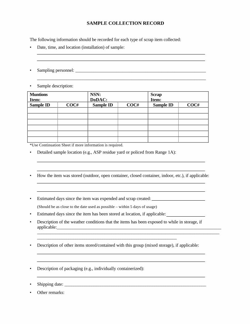
SAMPLE COLLECTION RECORD
The following information should be recorded for each type of scrap item collected:
• Date, time, and location (installation) of sample:
• Sampling personnel: __________________________________________________________
___________________________________________________________________________
• Sample description:
MuntionsItem:
NSN:DoDAC:
ScrapItem:
Sample ID COC# Sample ID COC# Sample ID COC#
*Use Continuation Sheet if more information is required.
• Detailed sample location (e.g., ASP residue yard or policed from Range 1A):
• How the item was stored (outdoor, open container, closed container, indoor, etc.), if applicable:
• Estimated days since the item was expended and scrap created:
(Should be as close to the date used as possible – within 5 days of usage)
• Estimated days since the item has been stored at location, if applicable:
• Description of the weather conditions that the items has been exposed to while in storage, ifapplicable:________________________________________________________________________________________________________________________________________________________________________________________________________________________
• Description of other items stored/contained with this group (mixed storage), if applicable:
• Description of packaging (e.g., individually containerized):
• Shipping date: _______________________________________________________________
• Other remarks:
Appendix E-2
RANGE SCRAP SAMPLE PREPARATION PROCEDURES
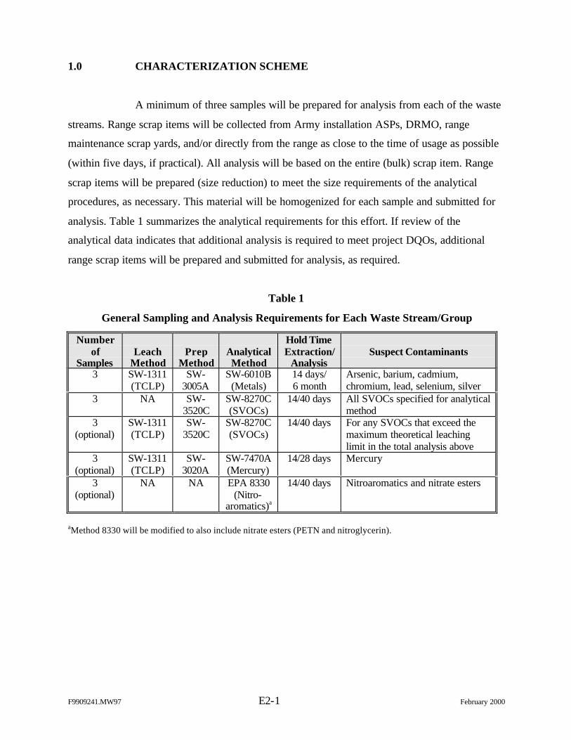
F9909241.MW97 E2-1 February 2000
1.0 CHARACTERIZATION SCHEME
A minimum of three samples will be prepared for analysis from each of the waste
streams. Range scrap items will be collected from Army installation ASPs, DRMO, range
maintenance scrap yards, and/or directly from the range as close to the time of usage as possible
(within five days, if practical). All analysis will be based on the entire (bulk) scrap item. Range
scrap items will be prepared (size reduction) to meet the size requirements of the analytical
procedures, as necessary. This material will be homogenized for each sample and submitted for
analysis. Table 1 summarizes the analytical requirements for this effort. If review of the
analytical data indicates that additional analysis is required to meet project DQOs, additional
range scrap items will be prepared and submitted for analysis, as required.
Table 1
General Sampling and Analysis Requirements for Each Waste Stream/Group
Numberof
SamplesLeach
MethodPrep
MethodAnalyticalMethod
Hold TimeExtraction/
AnalysisSuspect Contaminants
3 SW-1311(TCLP)
SW-3005A
SW-6010B(Metals)
14 days/6 month
Arsenic, barium, cadmium,chromium, lead, selenium, silver
3 NA SW-3520C
SW-8270C(SVOCs)
14/40 days All SVOCs specified for analyticalmethod
3(optional)
SW-1311(TCLP)
SW-3520C
SW-8270C(SVOCs)
14/40 days For any SVOCs that exceed themaximum theoretical leachinglimit in the total analysis above
3(optional)
SW-1311(TCLP)
SW-3020A
SW-7470A(Mercury)
14/28 days Mercury
3(optional)
NA NA EPA 8330(Nitro-
aromatics)a
14/40 days Nitroaromatics and nitrate esters
aMethod 8330 will be modified to also include nitrate esters (PETN and nitroglycerin).
F9909241.MW97 E2-2 February 2000
2. SAMPLE PREPARATION
Prior to submitting the scrap items to the analytical laboratory, they will undergo
size reduction at the project team’s facility or a materials engineering laboratory experienced in
preparing metallic samples for analysis. Items will be managed to ensure that materials (bulk or
residual) are not lost from the sample. Scrap items will be reduced in size by hand tools or
machined, as necessary, to achieve weight, size, and/or surface area requirements specified in the
analytical procedures.
2.1 Specification
This section describes the requirements for performing the sample preparation
(size reduction) required for range scrap items submitted for analysis.
2.1.1 TCLP particle size reduction
The range scrap items collected for this effort must be reduced in size per the
requirements of the TCLP extraction method 1311: “particle size reduction is required, unless the
solid has a surface area per gram of material equal to or greater than 3.1 cm2, or is smaller than 1
cm in its narrowest dimension (i.e. is capable of passing through a 9.5 mm standard sieve). If the
surface area is smaller or the particle size is larger than described above, prepare the waste for
extraction by crushing, cutting, or grinding the waste to a surface area or particle size as
described above.”
Size reduction for the metallic range scrap items may be accomplished by use of
hand tools and/or machining tools. Hand tools may include hand shears, diagonal cutters, pliers,
tubing cutters, and/or other hand tools typically used in the laboratory for sample preparation.
Electric or air-driven hand tools, such as an air-driven metal nibbler, that perform the same
function of the hand tools previously mentioned may also be utilized. A hand hacksaw may be
used on a limited basis, if necessary, for initial breakdown or separation of items.
F9909241.MW97 E2-3 February 2000
Some metallic range scrap items may also require limited machining for initial
breakdown or separation to accommodate use of the hand tools. Machining tools typically
include lathes, milling machines, various saws, and grinders. Saws and grinders are not
recommended for achieving size reduction due to the inability to control loss of materials. Saws
tend to accumulate very fine materials in the internal components of the machine. Likewise,
grinders tend to produce very fine particles that are hard to capture and account for. However,
lathes and milling machines of various types produce chips of material in a controlled manner.
Although both the lathe and milling machine can vary the width of chip of material produced, the
type of metal limits the depth of the material taken out of the item. The lathe can typically
achieve a depth closer to the TCLP requirement than a milling machine (2–9 mm for the lathe
versus 2 – 5 mm for the milling machine). For this reason and because the lathe is a more
common and readily available tool, the lathe is the recommended machining tool for use in
preparing samples. Note that mechanical/machining tools should only be used on a limited basis
to provide better access to materials for hand tools.
2.1.2 Loss of materials
The TCLP analysis must be based on the entire range scrap item. Therefore, the
sample preparation methods must prevent the loss of materials during size reduction. This should
be accomplished by ensuring that a container is always under the area of work to capture
materials generated during size reduction. A glove box may also be used, if available, to prevent
the loss of materials. Materials adhering to the surfaces of tools, which come into contact with
the scrap item, should also be removed and captured by brushing the tool or equivalent method.
2.1.3 Cross contamination
The tools used for sample preparation should be dedicated for this use and not
used for maintenance or other activities. Cross contamination between range scrap items will be
avoided by decontaminating tool surfaces, which come into contact with the items, with a
method that incorporates rinsing with a nitric acid solution (metal elimination) and isopropanol
(organic elimination). Tools shall be decontaminated between each use. Disposable gloves shall
also be used and changed for each sample processed.
F9909241.MW97 E2-4 February 2000
2.1.4 Temperature control
There may be a concern with the loss of constituents of concern during sample
preparation due to heating the surface of range scrap items, particularly when using a hacksaw or
lathe as described above. The goal of this sample preparation method is to limit the temperature
during all operations to a maximum of 60°C (140°F) for samples that will be analyzed for
SVOCs or explosives. This temperature, 60°C (140°F), is noticeable to the touch and is the
maximum temperature for handling materials without insulating gloves or other tools. It is
anticipated that out of all the tools approved for use and listed in Section 2.1.1, the hacksaw may
be the only one that will not achieve the temperature requirement. If this is the case, only the
lathe will be used for breaking down items as described in Section 2.1.1. A thermocouple should
be applied to the scrap item when using the lathe or hacksaw if the temperature threshold will
potentially be exceeded.
2.1.5 Providing a representative sample for analysis
The size reduction required to be performed on the range scrap items prior to
testing will physically separate the different components of an item (casing body, primer
assembly, base plate, etc.) into numerous individual pieces and separate the loose fine materials
from the bulk materials. The different components of the scrap item may contain differing
constituents of concerns and/or constituents at differing concentrations. These components must
be managed and reconfigured in a way that provides a material representative of the entire scrap
item to the analytical laboratory. This requirement presents the following challenge: The sample
directly subjected to analytical testing must, to the extent practical, contain the pieces of different
bulk components and the fine materials in an amount proportional to their weight in relation to
the entire scrap item.
In cases where an individual range scrap it em weighs less than the minimum
required sample weight (Section 2.5), representativeness is not as high of a concern regarding the
bulk materials since all the separated components/materials of the scrap item will be placed into
the sample container. However, in the cases where the scrap item weighs more than the
minimum sample weight, there is a concern that some of the bulk components of the item will
F9909241.MW97 E2-5 February 2000
not be placed into the sample container. To ensure this does not happen when processing an item
that weighs more than the minimum required sample weight, the pieces produced during size
reduction of the different components will be segregated during sample preparation. The
materials accumulated from each different component will be homogenized separately. The
appropriate sample containers will then be filled proportionally with pieces from all the different
components. The samples provided to the analytical laboratory will be further homogenized by
manually mixing the materials prior to testing.
The presence of loose fine materials associated with the scrap item presents a
different concern than that of the different bulk components. Even if a proportional amount of
fine materials are placed in the sample container, typical homogenization techniques will only
stratify the sample materials by size and weight, which will increase the likelihood that the fine
materials will accumulate at the bottom of the container and not be included in the materials
subjected to testing. Therefore, fine materials, when present, will be homogenized and
containerized separately in an amount proportional to the amount of bulk materials
containerized. Both containers will be submitted to the analytical laboratory with an attached
record of the ratio of bulk to fine materials that is to be maintained throughout testing. The
analytical laboratory must then composite the bulk and fine materials based on the weight ratio
provided when preparing an aliquot of material for testing.
2.2 Sample Preparation Procedure
The following procedure shall be followed for preparation of the samples for
analysis:
1. Follow an approved quality assurance plan and laboratory standard procedurefor sample receipt and internal COC. Obtain one field sample of the item to beprepared. If the weight of the item is less than 200 grams (minimum of 200grams are required to conduct TCLP, total SVOC, and explosive analyses,however, only 160 grams are required to conduct TCLP and total SVOCanalyses), obtain a sufficient number of additional items until the combinedweight exceeds 200 grams (160 grams when performing TCLP and totalSVOC analyses only). Confirm the minimum required sample weight with thespecific analytical laboratory to be used. Record the combined weight of the
F9909241.MW97 E2-6 February 2000
items to be processed to complete one sample on the Sample PreparationRecord (Section 2.9).
2. Don a new pair of disposable gloves between samples to prevent crosscontamination.
3. If the sample does not contain fine materials that can be separated from thebulk item, then proceed to step 4. If the sample contains fine materials that canbe separated from the bulk item, then perform the following:
Ø Carefully open the plastic container for the item over a secondarycontainer (Container A) to retain any loose materials.
Ø Remove the remainder of loose materials with a stainless steel ordisposable spoon/spatula or similar tool.
Ø Record the weight of the fine material captured in Container A on theSample Preparation Record (Section 2.9).
4. If no portion of the item can be processed (size reduction) using hand tools,then proceed to step 5. Otherwise, reduce the size of the item to meet thesample preparation requirements using hand tools. Hand tools will consist ofhand shears, diagonal cutters, pliers, tubing cutters, and an air-driven metalnibbler. A hand hacksaw may be used on a limited basis, if necessary, asdescribed in Section 2.1.1. Perform size reduction over plastic sheeting orother container to collect materials. Hand tools will be used inside a dedicatedglove box when possible. If there are any materials that require processing bymilling tools, then proceed to step 5. If no portion of the item requiresprocessing by milling tools, then proceed to step 6.
5. Some metal items may require limited machining for initial breakdown. Usingan acceptable milling tool (Section 2.1.1), reduce the size of those portions ofthe item that cannot be prepared with hand tools. Perform this size reductionover plastic sheeting or other container to collect materials. Use hand tools tofurther reduce the size of particles as needed (refer to step 4).
6. Consolidate materials from all containers or plastic linings, which have beenused to control loss of materials, into Container B. Visually inspect thecontents of Container B to identify any materials obviously not meeting thesize reduction requirement (Section 2.1.1). Repeat steps 4 through 6 asnecessary.
7. Sift the contents of Container B through a standard 9.5 mm or 0.375-in sieveand capture the materials in Container C. Return any materials not passingthrough the sieve to Container B and repeat steps 4 through 7.
8. Fill the sample container for TCLP analysis. TCLP analysis must be based onthe entire scrap item to provide a representative sample (Section 2.1.5) byperforming the following:
Ø If the scrap item being sampled weighs less than or equal to 100 grams(bulk and fine materials combined, if applicable), then process (sizereduction) a sufficient number of items (always processing the entire scrapitem) to exceed the 100 grams required for TCLP analysis and place all
F9909241.MW97 E2-7 February 2000
the material directly into the TCLP sample container (Section 2.5). If thereare fine materials associated with the scrap item, then refer to step 11.
Ø If the item being sampled weighs more than 100 grams (bulk and finematerials combined, if applicable), then completely process one item.Segregate different components (primer components, base plate, casing,etc.) of the item, if applicable. Homogenize (Section 2.4) materialsaccumulated from each different component separately. Fill theappropriate sample container (Section 2.5) with a minimum of 100 gramsof material by placing a proportional amount of each different componentinto the container. Remaining material may be used to fill the containerrequired for total SVOC and explosive analyses, step 9 and 10. If there arefine materials associated with the scrap item, then refer to step 11.
9. Fill the sample container for total SVOC analysis. A representative samplewill be provided by conducting the following:
Ø If the scrap item being sampled weighs less than or equal to 30 grams(bulk and fine materials combined, if applicable), then process (sizereduction) a sufficient number of items (always processing the entire scrapitem) to exceed the 30 grams required for total SVOC analysis and placeall the material directly into the appropriate sample container (Section2.5). If there are fine materials associated with the scrap item, then refer tostep 11.
Ø If the item being sampled weighs more than 30 grams (bulk and finematerials combined, if applicable), then completely process one item.Segregate different components (primer components, base plate, casing,etc.) of the item, if applicable. Homogenize (Section 2.4) materialsaccumulated from each different component separately. Fill theappropriate sample container (Section 2.5) with a minimum of 30 grams ofmaterial by placing a proportional amount of each different componentinto the container. Remaining material may be used to fill the containerrequired for explosive analysis, step 10. If there are fine materialsassociated with the scrap item, then refer to step 11.
Ø Fill the sample container for explosive analysis. A representative samplewill be provided by conducting the following:
Ø If the scrap item being sampled weighs less than or equal to 20 grams(bulk and fine materials combined, if applicable), then process (sizereduction) a sufficient number of items (always processing the entire scrapitem) to exceed the 20 grams required for explosive analysis and place allthe material directly into the appropriate sample container (Section 2.5). Ifthere are fine materials associated with the scrap item, then refer to step11.
Ø If the item being sampled weighs more than 20 grams (bulk and finematerials combined, if applicable), then completely process one item.Segregate different components (primer components, base plate, casing,etc.) of the item, if applicable. Homogenize (Section 2.4) materialsaccumulated from each different component separately. Fill the
F9909241.MW97 E2-8 February 2000
appropriate sample container (Section 2.5) with a minimum of 20 grams ofmaterial by placing a proportional amount of each different componentinto the container. If there are fine materials associated with the scrapitem, then refer to step 11.
10. Fine materials must be managed in a way to ensure a representative aliquot ofthe sample is taken in the laboratory and subjected to the required testing(Section 2.1.5). Determine the ratio of fine material to bulk material from theinformation recorded in steps 1 and 3 in accordance with the instructions onthe Sample Preparation Record (Section 2.9). Homogenize (Section 2.4) thefine materials accumulated and place the appropriate amount of fine material(based on the amount of bulk material containerized in steps 9, 10, and 11)into a separate container marked for the same analysis. Instructions must besent with the COC/analytical request that provide the analytical laboratorywith the ratio of bulk and fine materials to be maintained when preparing analiquot of the sample for testing.
11. Label sample containers, apply sample seals, complete chain-of-custodyforms, and complete required documentation as discussed in Sections 2.6, 2.7,2.8, and 2.9 respectively.
12. Decontaminate tools and equipment as described in Section 2.10.
13. Collect excess materials in plastic bags and record the scrap type on theexterior of the bag. Seal bags and return to the installation point of contact thatprovided the item. Otherwise, store the accumulated bags and dispose of thematerials based on the results of the analytical testing and in accordance withfederal, state, and local requirements.
Figures 1 and 2 provide an example of the flow of sample preparation for a small and large scrap
item, respectively
2.3 Quality Assurance/Quality Control Samples
QA Rinsate blank samples will be prepared at a rate of 1 blank per 20 samples
prepared (5%). Equipment/tool rinsate blanks will be performed by collecting laboratory grade,
deionized water that has been rinsed over decontaminated equipment/tool surfaces that contacted
the range scrap item during sample preparation.
QC split samples will be collected at a rate of 1 split sample per 20 samples
prepared (5%). Samples targeted for QC will be prepared as stated in Section 2.2, but at least 400
grams of material will be processed. The QC split sample will be performed after the material
has been homogenized by filling an additional sample container for each analysis. All sample
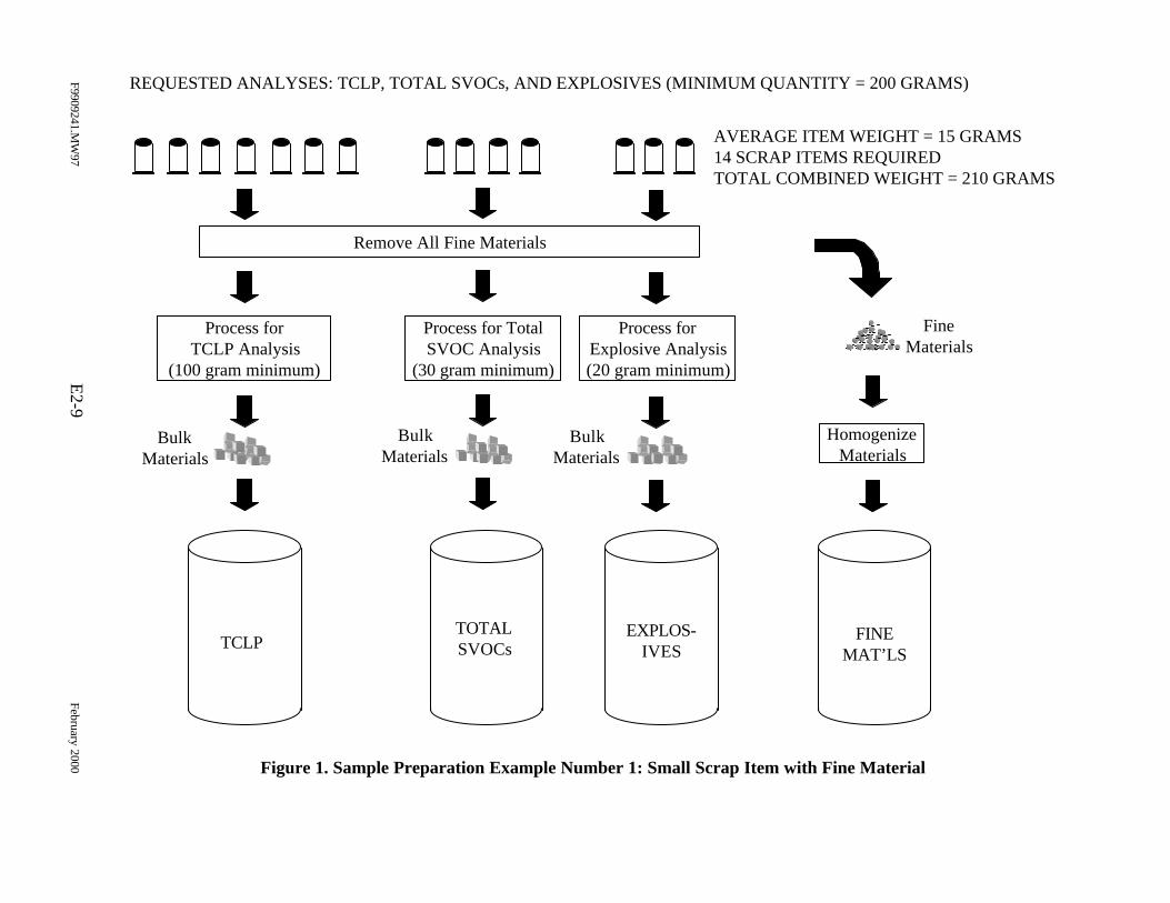
Figure 1. Sample Preparation Example Number 1: Small Scrap Item with Fine Material
F9909241.MW
97E
2-9February 2000
TCLPTOTALSVOCs
EXPLOS-IVES
FINEMAT’LS
REQUESTED ANALYSES: TCLP, TOTAL SVOCs, AND EXPLOSIVES (MINIMUM QUANTITY = 200 GRAMS)
AVERAGE ITEM WEIGHT = 15 GRAMS14 SCRAP ITEMS REQUIREDTOTAL COMBINED WEIGHT = 210 GRAMS
Process forTCLP Analysis
(100 gram minimum)
Process for TotalSVOC Analysis
(30 gram minimum)
Process forExplosive Analysis(20 gram minimum)
Remove All Fine Materials
BulkMaterials
BulkMaterials
BulkMaterials
FineMaterials
HomogenizeMaterials
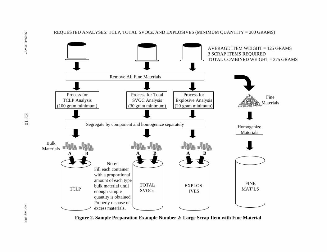
Figure 2. Sample Preparation Example Number 2: Large Scrap Item with Fine Material
F9909241.MW
97E
2-10February 2000
TCLPTOTALSVOCs
EXPLOS-IVES
FINEMAT’LS
REQUESTED ANALYSES: TCLP, TOTAL SVOCs, AND EXPLOSIVES (MINIMUM QUANTITY = 200 GRAMS)
AVERAGE ITEM WEIGHT = 125 GRAMS3 SCRAP ITEMS REQUIREDTOTAL COMBINED WEIGHT = 375 GRAMS
Process forTCLP Analysis
(100 gram minimum)
Process for TotalSVOC Analysis
(30 gram minimum)
Process forExplosive Analysis(20 gram minimum)
Remove All Fine Materials
HomogenizeMaterials
FineMaterials
Segregate by component and homogenize separately
BulkMaterials
A B A B A B
Note:Fill each containerwith a proportionalamount of each typebulk material untilenough samplequantity is obtained.Properly dispose ofexcess materials.
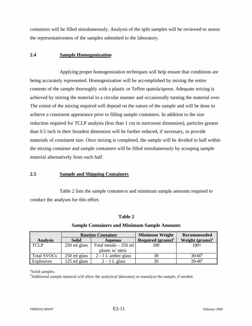
F9909241.MW97 E2-11 February 2000
containers will be filled simultaneously. Analysis of the split samples will be reviewed to assess
the representativeness of the samples submitted to the laboratory.
2.4 Sample Homogenization
Applying proper homogenization techniques will help ensure that conditions are
being accurately represented. Homogenization will be accomplished by mixing the entire
contents of the sample thoroughly with a plastic or Teflon spatula/spoon. Adequate mixing is
achieved by stirring the material in a circular manner and occasionally turning the material over.
The extent of the mixing required will depend on the nature of the sample and will be done to
achieve a consistent appearance prior to filling sample containers. In addition to the size
reduction required for TCLP analysis (less than 1 cm in narrowest dimension), particles greater
than 0.5 inch in their broadest dimension will be further reduced, if necessary, to provide
materials of consistent size. Once mixing is completed, the sample will be divided in half within
the mixing container and sample containers will be filled simultaneously by scooping sample
material alternatively from each half.
2.5 Sample and Shipping Containers
Table 2 lists the sample containe rs and minimum sample amounts required to
conduct the analyses for this effort.
Table 2
Sample Containers and Minimum Sample Amounts
Routine ContainerAnalysis Solid Aqueous
Minimum WeightRequired (grams)a
RecommendedWeight (grams)a
TCLP 250 ml glass Total metals – 250 mlplastic w/ nitric
100 100+
Total SVOCs 250 ml glass 2 - 1 L amber glass 30 30-60b
Explosives 125 ml glass 2 – 1 L glass 20 20-40b
aSolid samples.bAdditional sample material will allow the analytical laboratory to reanalyze the sample, if needed.
F9909241.MW97 E2-12 February 2000
Standard food/beverage coolers designated solely for sample shipment shall be
used for shipping the samples prepared for this effort. A copy of the COC record, shipping
waybill, and “inert certification” shall be included in each shipping container. The contents of the
shipping container should be specified as “environmental samples”.
2.6 Sample Labeling
Samples will be labeled at the time sample containers are filled. The label will
contain the following information:
Ø Sample identifier,
Ø Requested analysis
Ø Date and time of collection, and
Ø Sampler initials.
This information will be written on a label affixed to the container. Sample label information
should be completed using indelible ink.
2.7 Sample Seals
Sample seals are used to preserve the integrity of the sample from the time it is
collected until it is opened in the analytical laboratory. Gummed paper or plastic is used as
official sample seals. These seals will be applied to the outside of shipping packages.
2.8 Sample COC and Analytical Request
All samples submitted to the analytical laboratory will be documented on a
standard COC form. If samples are hand delivered to the laboratory, the sampler, the courier (if
other than the sampler), and the receiver will sign the form. If samples are shipped via an
overnight express service, the number of the waybill will be substituted for the receiver
signature. The laboratory receiving clerk must still sign the COC to acknowledge receipt at the
laboratory.
F9909241.MW97 E2-13 February 2000
The COC/analytical request will include the following minimum information:
Ø Place of collection (sample identification),
Ø Data and time of collection,
Ø Sample type (grab or composite),
Ø Sample description,
Ø Requested analyses,
Ø Number of containers,
Ø Signatures of personnel involved in the chain of possession,
Ø Inclusive dates of possession, and
Ø Instructions or reference to an attachment that provides additional instructionsto the analytical laboratory regarding non-routine activities.
2.9 Sample Preparation Documentation
Attachment A contains a Sample Preparation Record that will be used to record
the sample preparation information.
2.10 Equipment/Tools Decontamination
Equipment and tools that are reused during sample preparation will be
decontaminated as follows:
1. Wipe the equipment with a laboratory grade wipe that has been saturated witha 2% nitric acid solution.
2. Rinse thoroughly with distilled water.
3. Rinse with laboratory grade isopropanol.
4. Rinse thoroughly with laboratory grade organic-free water.
5. Dry the equipment with laboratory grade disposable wipes.
Unless the equipment is going to be used immediately, it should be stored in a clean place (on
plastic sheeting).
Attachment E-2
SAMPLE PREPARATION RECORD
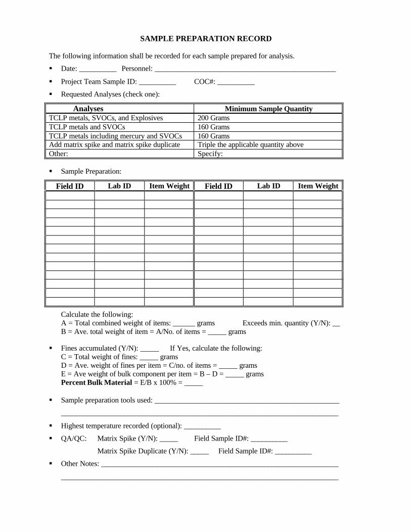
SAMPLE PREPARATION RECORD
The following information shall be recorded for each sample prepared for analysis.
§ Date: __________ Personnel: _________________________________________________
§ Project Team Sample ID: __________ COC#: __________
§ Requested Analyses (check one):
Analyses Minimum Sample QuantityTCLP metals, SVOCs, and Explosives 200 GramsTCLP metals and SVOCs 160 GramsTCLP metals including mercury and SVOCs 160 GramsAdd matrix spike and matrix spike duplicate Triple the applicable quantity aboveOther: Specify:
§ Sample Preparation:
Field ID Lab ID Item Weight Field ID Lab ID Item Weight
Calculate the following:A = Total combined weight of items: ______ grams Exceeds min. quantity (Y/N): __B = Ave. total weight of item = A/No. of items = _____ grams
§ Fines accumulated (Y/N): _____ If Yes, calculate the following:C = Total weight of fines: _____ gramsD = Ave. weight of fines per item = C/no. of items = _____ gramsE = Ave weight of bulk component per item = B – D = _____ gramsPercent Bulk Material = E/B x 100% = _____
§ Sample preparation tools used: __________________________________________________
___________________________________________________________________________
§ Highest temperature recorded (optional): __________
§ QA/QC: Matrix Spike (Y/N): _____ Field Sample ID#: __________
Matrix Spike Duplicate (Y/N): _____ Field Sample ID#: __________
§ Other Notes: ________________________________________________________________
___________________________________________________________________________

Appendix E-3
RANGE SCRAP ANALYTICAL PROCEDURES
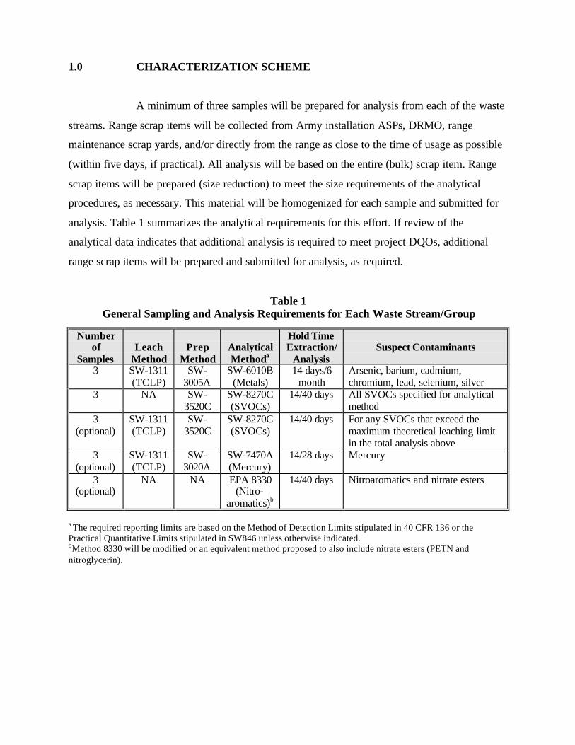
1.0 CHARACTERIZATION SCHEME
A minimum of three samples will be prepared for analysis from each of the waste
streams. Range scrap items will be collected from Army installation ASPs, DRMO, range
maintenance scrap yards, and/or directly from the range as close to the time of usage as possible
(within five days, if practical). All analysis will be based on the entire (bulk) scrap item. Range
scrap items will be prepared (size reduction) to meet the size requirements of the analytical
procedures, as necessary. This material will be homogenized for each sample and submitted for
analysis. Table 1 summarizes the analytical requirements for this effort. If review of the
analytical data indicates that additional analysis is required to meet project DQOs, additional
range scrap items will be prepared and submitted for analysis, as required.
Table 1General Sampling and Analysis Requirements for Each Waste Stream/Group
Numberof
SamplesLeach
MethodPrep
MethodAnalyticalMethoda
Hold TimeExtraction/
AnalysisSuspect Contaminants
3 SW-1311(TCLP)
SW-3005A
SW-6010B(Metals)
14 days/6month
Arsenic, barium, cadmium,chromium, lead, selenium, silver
3 NA SW-3520C
SW-8270C(SVOCs)
14/40 days All SVOCs specified for analyticalmethod
3(optional)
SW-1311(TCLP)
SW-3520C
SW-8270C(SVOCs)
14/40 days For any SVOCs that exceed themaximum theoretical leaching limitin the total analysis above
3(optional)
SW-1311(TCLP)
SW-3020A
SW-7470A(Mercury)
14/28 days Mercury
3(optional)
NA NA EPA 8330(Nitro-
aromatics)b
14/40 days Nitroaromatics and nitrate esters
a The required reporting limits are based on the Method of Detection Limits stipulated in 40 CFR 136 or thePractical Quantitative Limits stipulated in SW846 unless otherwise indicated.bMethod 8330 will be modified or an equivalent method proposed to also include nitrate esters (PETN andnitroglycerin).
2.0 SAMPLE ANALYSIS
2.1 Analytical Methods/Procedures
The subcontract laboratory used for this study shall be certified by the U.S. Army
Corps of Engineers Missouri River District for the applicable methods. The analytical procedures
for this project are specified as a sample matrix in Table 1. Chemical analyses will be performed
in accordance with the following guidelines:
Ø SW-846, Test Methods for Evaluating Solid Waste: Physical/ChemicalMethods, EPA Office of Solid Waste and Emergency Response, November1986 and
Ø EPA, Method for Chemical Analysis of Water and Wastes, EPA/600/4-79-020,March 1993.
As stated earlier, Modified Method 8330 will be used for the analysis of
nitroglycerin and PETN. The difference between the two methods (8330 and Modified 8330) is
the addition of a salting out procedure used for 8330. This procedure allows for lower (i.e., more
sensitive) detection limits of the analytes.
Analytical data report packages will be provided at an EPA “Level III” format or
U.S. Army Corps of Engineers standard data reporting format as described below:
A standard reporting format will be used to report all data along with thesupporting QC information. The standard data reporting format will include,at a minimum, a general discussion, analytical data for field samples andQC samples, calibration information, laboratory performance and matrix-specific information, and any other information that is pertinent to theproject samples. Electronic format will be provided in Microsoft Excel.
Attachment A provides an example specification for analytical services, which may be used in
procuring a laboratory for analysis of range scrap items.
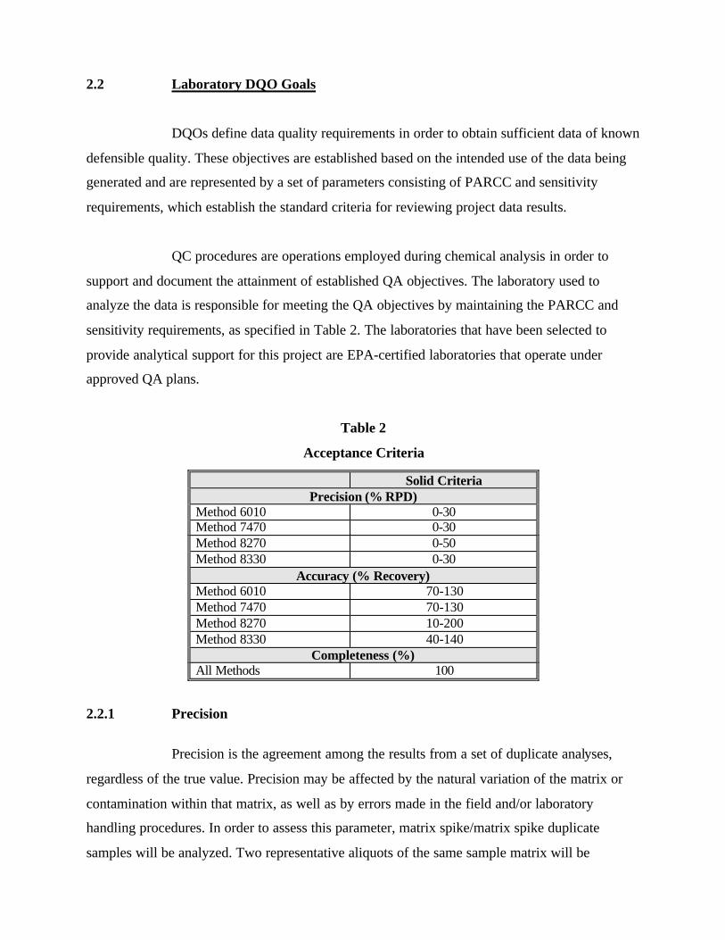
2.2 Laboratory DQO Goals
DQOs define data quality requirements in order to obtain sufficient data of known
defensible quality. These objectives are established based on the intended use of the data being
generated and are represented by a set of parameters consisting of PARCC and sensitivity
requirements, which establish the standard criteria for reviewing project data results.
QC procedures are operations employed during chemical analysis in order to
support and document the attainment of established QA objectives. The laboratory used to
analyze the data is responsible for meeting the QA objectives by maintaining the PARCC and
sensitivity requirements, as specified in Table 2. The laboratories that have been selected to
provide analytical support for this project are EPA-certified laboratories that operate under
approved QA plans.
Table 2
Acceptance Criteria
Solid CriteriaPrecision (% RPD)
Method 6010 0-30Method 7470 0-30Method 8270 0-50Method 8330 0-30
Accuracy (% Recovery)Method 6010 70-130Method 7470 70-130Method 8270 10-200Method 8330 40-140
Completeness (%)All Methods 100
2.2.1 Precision
Precision is the agreement among the results from a set of duplicate analyses,
regardless of the true value. Precision may be affected by the natural variation of the matrix or
contamination within that matrix, as well as by errors made in the field and/or laboratory
handling procedures. In order to assess this parameter, matrix spike/matrix spike duplicate
samples will be analyzed. Two representative aliquots of the same sample matrix will be
subjected to identical analytical procedures in order to assess the procedural precision of the
method through the calculation of relative percent difference (RPD). This value will be used to
ensure precision objectives have been met. Method-specific RPD limits will be provided in the
laboratory-specific reports of results. The number of matrix spike and matrix spike duplicate
samples will be determined in accordance with the specified methods.
2.2.2 Accuracy
Accuracy is defined as the closeness of agreement between the measured value
and the true value and is calculated as percent recovery. Sources of error include the sampling
process, field contamination, preservation, handling, sample matrix, sample preparation, and
analysis techniques. Analytical accuracy will be assessed by measuring the percent recovery of
known concentrations of target analytes spiked into a field sample (matrix spikes). Method-
specific percent recovery limits will be provided in the laboratory-specific reports of results.
2.2.3 Representativeness
Representativeness expresses the degree to which sample data accurately and
precisely represent the characteristics of a population of samples or an environmental condition.
Employing appropriate sampling strategies as described in Section 3.2 will ensure
representativeness. In the laboratory, representativeness may be enhanced by making certain that
all subsamples taken from a given sample are representative of the entire sample.
Representativeness will be assessed by the use of duplicate field and laboratory samples.
For the laboratory (matrix) duplicates, two representative aliquots of the same
sample matrix will be subjected to identical analytical procedures. The RPD between the two
sample results will be calculated.
2.2.4 Comparability
Comparability is the confidence with which one data set can be compared to
another. Sample data will be comparable with other measurement data for similar samples and
sample conditions. This goal will be achieved by using standard methods for sample collection,
sample analysis, data review, reporting data in standard units, and using standard and
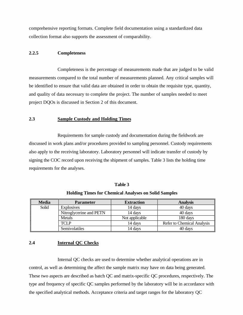
comprehensive reporting formats. Complete field documentation using a standardized data
collection format also supports the assessment of comparability.
2.2.5 Completeness
Completeness is the percentage of measurements made that are judged to be valid
measurements compared to the total number of measurements planned. Any critical samples will
be identified to ensure that valid data are obtained in order to obtain the requisite type, quantity,
and quality of data necessary to complete the project. The number of samples needed to meet
project DQOs is discussed in Section 2 of this document.
2.3 Sample Custody and Holding Times
Requirements for sample custody and documentation during the fieldwork are
discussed in work plans and/or procedures provided to sampling personnel. Custody requirements
also apply to the receiving laboratory. Laboratory personnel will indicate transfer of custody by
signing the COC record upon receiving the shipment of samples. Table 3 lists the holding time
requirements for the analyses.
Table 3
Holding Times for Chemical Analyses on Solid Samples
Media Parameter Extraction AnalysisSolid Explosives 14 days 40 days
Nitroglycerine and PETN 14 days 40 daysMetals Not applicable 180 daysTCLP 14 days Refer to Chemical AnalysisSemivolatiles 14 days 40 days
2.4 Internal QC Checks
Internal QC checks are used to determine whether analytical operations are in
control, as well as determining the affect the sample matrix may have on data being generated.
These two aspects are described as batch QC and matrix-specific QC procedures, respectively. The
type and frequency of specific QC samples performed by the laboratory will be in accordance with
the specified analytical methods. Acceptance criteria and target ranges for the laboratory QC
samples are presented within the analytical methods and summarized in Table 2. Data that vary
from these target ranges will result in the implementation of appropriate corrective measures. Full
documentation of all actions taken will be recorded within a case narrative.
2.4.1 Batch QC
Typical batch QC for analyses to be performed for this project is described below.
Method Blanks. Method blanks are analyzed to assess the level of background
interference or contamination that exists in the analytical system and that might lead to the
reporting of elevated concentration levels or false positive data. At least one method blank will
be prepared and analyzed with every batch of samples processed. The concentration of all target
analytes in the blank will be below the MDL or 5% of the measured concentration in the sample.
If the blank does not meet acceptance criteria, the source of contamination will be investigated
and appropriate corrective action will be taken and documented. Corrective actions may include
reanalysis of the blank and/or re-preparation and reanalysis of the blank and all associated
samples at the laboratory’s cost. Sample results will not be corrected for blank contamination.
Laboratory Control Samples. Laboratory performance QC will be based on the
use of standard control matrices that are prepared independently from the standard solutions used
in establishing the calibration curve, to calculate precision and accuracy data. These QC data will
be compared on a per-batch basis, to the control limits of the methods, to verify compliance. This
data, along with method blank data, will be used to assess laboratory performance.
Other QC Samples. In order to maintain the quality of the data and laboratory
performance, the laboratory will implement the QC requirements and standards described in the
reference methods that is uses. These method-specific QC requirements include the following:
Ø Initial Calibration (metals and SVOCs);
Ø Initial Calibration Verification (metals);
Ø Initial Calibration Blank and Continuing Calibration Blank (metals);
Ø Continuing Calibration Verification (metals, explosives, and SVOCs);
Ø Interference Check Sample (metals);
Ø Tune (SVOCs);
Ø Linear Range Analysis (metals);
Ø Method Blank (metals, explosives, and SVOCs);
Ø Serial Dilution (metals);
Ø Laboratory Control Sample (metals, explosives, and SVOCs);
Ø Surrogate Spike (SVOCs); and
Ø Matrix spikes (metals, explosives, and SVOCs).
2.4.2 Matrix-Specific QC
Matrix-specific QC will be based on the use of an actual environmental sample
for precision and accuracy determinations and will rely on the analysis of matrix duplicates,
surrogate compounds, matrix spikes, and matrix spike duplicates. The required frequency of
these sample types is established within each specific analytical method. Results of these
samples will be used to assess the affect of sample matrix conditions on analytical data.
Attachment E-3
EXAMPLE SPECIFICATIONS FOR ANALYTICAL SERVICES
Example Specifications for Analytical Services
QA/QC Element Project Minimum Acceptable Level
1. Sample Custody A record of COC must be discernible for "individual sample containers"while they are in the possession of the laboratory. A copy of the originalcomplete COC record must be provided with the results for each sample aspart of the hardcopy deliverable.
2. Sample Receipt The laboratory must be able to receive and store sample shipments(including weekends and holidays) without compromising the integrity ofthe samples. The laboratory must note on the COC form when samples arereceived.
3. Holding Times Where holding times have been specified in the published method (e.g., 40CFR 136, SW-846), the laboratory is expected to meet those holding timeswithout exception. Evidence of hold time compliance must be reported withthe results for each sample. The laboratory should maintain a real-timesystem for determining percent compliance.
4. Published Method Compliance Where published methods for analysis exist, those methods will be followed(in most cases, the latest version of the method) without exception unlessexceptions are requested by THE PROJECT TEAM or our client. Allexceptions must be agreed to in writing and before award is made.
5. Standard Traceability A clear record must exist for each result to show what material was used asthe reference standard. All dilutions and preparations of standard materialsmust be documented in a permanent record. Each standard preparation mustbe uniquely identified such that no two preparations could be confused in theevidentiary files.
6. Reporting of AnalyticalMeasurement Results
Results for analytical measurements will be reported in a consistent,standardized format. The laboratory must be able to report with eachconstituent measurement result with the minimum detection andcorresponding reporting limit determined, adjusted for sample specificpreparation activities. All reported measurements must be obtained from asystem operated in a state of "statistical control," as evidenced by batch QCmeasurements which fall within the laboratory's Standard OperatingProcedures (SOPs), and associated QA manuals. If the batch QC indicatesthat the system is not in control, corrections must be made, and samplesreanalyzed. If it is not possible to reanalyze samples using an in-controlsystem, the sample result may be flagged with a qualifier. No sample resultsmay be reported from an out of control system without incurring penalties asdescribed in Item 13. If the batch QC measurements and sample reanalysisindicate that the system is in control and that the sample matrix is the causeof QC measurements falling outside of specifications, the data may beflagged without penalty and will not be counted against the completenessobjective, as would out-of-control system results described above.
7. QC Data Reporting Results for QC measurements relevant to each analytical measurement mustbe maintained in a consistent, standardized format. For each QCmeasurement, the theoretical value, the quality objective and the calculatederror (in terms of the quality objective for the measurement) must bemaintained in a permanent record. The same information reported forsamples must also be reported for analytical QC samples. It must be clearfrom the QC data report that the correct QC measurements have been madefor the method employed and what the outcome was. Relevant QCmeasurement data (e.g., method blank, laboratory control sample, calibrationstandards) must be maintained in a consistent, standardized format andreported with the results for each sample in a manner that allowsdetermination that the required frequency of analytical QC samples wereanalyzed with each "batch" of samples.
QA/QC Element Project Minimum Acceptable Level
8. Electronic Transfer of Data The laboratory must have the ability to transfer information for Items 3, 6,and 7 in predefined, consistent, standardized data files or equivalent asagreed to by THE PROJECT TEAM and the laboratory subcontractor. Eachdata file must contain the exact information as the corresponding hard copyrecord except for the COC form(s) and case narrative. The structure of thesefiles must be held constant for the duration of this subcontract unless achange is requested by THE PROJECT TEAM.
9. Turn Around Time (TAT) The laboratory will complete all analyses and be able to report measurementdata (as per Items 1, 3, 4, 6, 7, and 8) in electronic format within thefollowing required TAT (14 days) to ensure reporting requirements are met.The hardcopy report for the submitted data may be received by THEPROJECT TEAM up to 5 working days after the electronic data issubmitted.
10. Disposal Samples must be kept in laboratory storage for at least 2 months. Once thesample disposal is approved by THE PROJECT TEAM, the laboratory willincur all costs associated with disposal of samples. The laboratory isresponsible for the transportation of all associated laboratory waste productsto an approved waste disposal facility in accordance with U.S. Departmentof Transportation, U.S. Environmental Protection Agency, U.S. NRC,federal, and state regulations. THE PROJECT TEAM retains the right toaudit the laboratory for evidence of proper disposal.
11. Recordkeeping The laboratory will maintain a recordkeeping system that can reproduce an"evidentiary file" adequate for use in legal defense of analyticalmeasurements. This should include but is not limited to evidence of COC,sample preparation, instruments, preservation, standard traceability,calibration, the actual measurement, and all other QC measurements.Additional records such as instrument run logs, maintenance logs, personal(analyst) logs and analysis related correspondence may be necessary todefend some types of measurement data.
12. Archiving The laboratory is required to maintain in a retrievable medium allinformation relevant to the analysis of THE PROJECT TEAM samples for aperiod of at least 10 years from the date of sample receipt. Transfer of rawdata to THE PROJECT TEAM custody may be required in the event the datamust be maintained for a longer period of time.
13. Penalties Non-Defensible Sample Analysis Results. In cases where the results reportedby the laboratory are found to be non-defensible due to laboratory handlingof the sample or related laboratory measurement information, or due tomissing or inadequate documentation such that results cannot be reproducedor recalculated from the raw data and laboratory records, those findings willresult in nonpayment for all associated samples. If non-defensible results aredetermined to be "critical" to meeting the objectives of THE PROJECTTEAM, the laboratory will be required to pay THE PROJECT TEAM costsdirectly related to resampling including, for example, labor, materials, andshipment expenses. THE PROJECT TEAM will minimize the costs ofresampling by combining these efforts with other field activities.Non-compliant Sample Analytical Results. THE PROJECT TEAM shallhave three months from receipt of analytical data (including associatedQA/QC information) to identify sample results which are non-compliantwith system control requirements. Should the non-compliant sample resultsbe "critical" to meeting the objectives of THE PROJECT TEAM, resamplingand reanalysis will be required at the laboratory's expense.
QA/QC Element Project Minimum Acceptable Level
Corrective Action TAT Non-compliance. In cases where the resultsreported by the laboratory are found to be indefensible, unusable, orboth, based on initial review of hard copy reports by THE PROJECTTEAM QC staff, a rejection of the data package will occur. Theunacceptable data package will be returned to the subcontractor, withwritten comments on the hard copy report explaining reasons forrejection (i.e., incorrect calculations, incorrect reporting limits,insufficient batch QC, etc.). Once notification of data package rejectionis given, THE PROJECT TEAM will expect corrective actions be takento deliver a defensible written response or error-free reissuance of thehard copy report within (14) calendar days. If final resolution ofidentified problems takes more than (14) calendar days, payment tosubcontractor will be discounted according to the following schedule:
PERCENT OFDAYS LATE COMPENSATION WITHHELD 1 - 7 20% 8 - 14 40% > 14 100%
The (14) day corrective action TAT schedule begins on the initial date ofproblem notification.
14. Price The cost of analytical services shall not be escalated during the period thatthis subcontract is in effect. The laboratory QC samples should be includedin cost per THE PROJECT TEAM field sample. Any anticipated annual costescalation factors shall be indicated in the response to this SOW
15. Laboratory Certifications/
License
The laboratory will maintain all certifications required to comply with theobjectives of THE PROJECT TEAM for given sets of samples. For thisprogram, MRD certification and approval is required.