Embed Size (px)
Citation preview
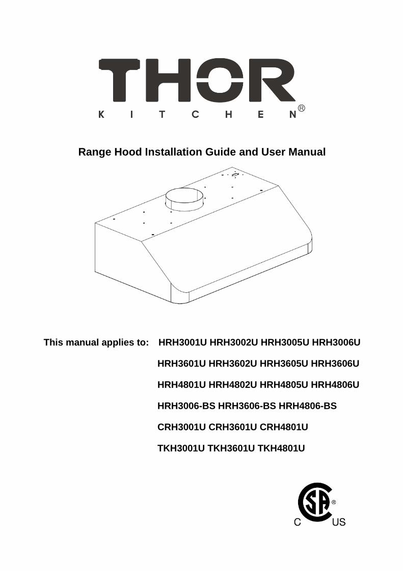
Range Hood Installation Guide and User Manual
This manual applies to: HRH3001U HRH3002U HRH3005U HRH3006U
HRH3601U HRH3602U HRH3605U HRH3606U
HRH4801U HRH4802U HRH4805U HRH4806U
HRH3006-BS HRH3606-BS HRH4806-BS
CRH3001U CRH3601U CRH4801U
TKH3001U TKH3601U TKH4801U
1
Safety Notice Your Thor Kitchen Range hood is designed and approved for residential use only. The warranty will be
void if apply for commercial use.
Please read instructions completely before starting.
The installation of the appliance must apply to local codes.
Important: Save instruction so that it may be provided to your installer in your local area.
Safety Warning: Turn off the circuit breaker at your electrical panel before connecting to a power source.
Power requirement: 110V-120V/60HZ.
CAUTION: THIS PRODUCT IS FOR GENERAL RESIDENTIAL USE ONLY. DO NOT USE THIS PRODUCT TO
EXHAUST FUMES OR HAZARDOUS OR EXPLOSIVE GAS
WARNING: TO REDUCE THE RISK OF FIRE, ELECTRICAL SHOCK OR INJURY TO PEOPLE, PLEASE BE AWARE
OF THE FOLLOWING REQUIREMENT:
1. For Any product maintenance, please cut off the power to prevent accidentally activating the power.
2. A qualified installer is required to perform the installation and wiring of the electricity in accordance
with all codes and standards in your local areas, including fire resistance rating.
3. It is recommended to provide proper evacuation of gas through the chimney pipe to prevent back
flow of air. Follow the instructions and safety standards of the manufacturer heating equipment,
such as those published by the National Fire Protection Association (NFPA), the American Society for
Heating, Refrigeration and Air Conditioning Engineers (ASJRAE) and the code authorities in your area.
4. When cutting or drilling into a wall or ceiling, please take extra care not to damage electrical wiring
or other wiring layout.
5. It’s required that holding plate (mounting plate) needs to be anchored in studs – the wall alone will
not be strong enough to support range hood’s weight. The center of a stud provides the best
support for the range hood. At least one Drywall Screw set needs to be mounted into stud.
6. Always evacuate outside through a conduct system.
To reduce the risk of fire and to properly vent air, make sure that the pipe is leading outside, do not
vent system into the space between the walls, ceilings, attics, crawl spaces or garages.
WARNING:
TO REDUCE THE RISK OF FIRE, USE ONLY METAL DUCT, install this hood in accordance with all
requirements mentioned.
WARNING:
1. Never leave the stove unattended when in use. Cooking oils at high temperature will cause smoke
which could be ignited.
2. Always operate the hood when using the top burners / oven function
3. Clean ventilating fans frequently. Do not let grease accumulated on the filters or fan blades.
4. Use proper pan size for cooking. Always use an appropriate pot size on your range.
5. Do not touch working LED during operation.
WARNING:
2
TO AVOID INJURIES IN A GREASE FIRE, PLEASE FOLLOW THE FOLLOWING:
1. Put out the fire with a lid according dimension of the cooking pot, or baking & cookie sheet or other
metal tray, then turn off the gas or power supply of the stove. If the flames do not go out immediately,
CALL THE FIRE DEPARTMENT IMMEDIATELY.
2. DO NOT USE WATER TO PUT OUT FIRE ON A RANGE, including wet dish towels.
3. Use an extinguisher only if:
3.1 Make sure to have a Class ABC extinguisher;
3.2 The fire is confined to the area where it was formed.
3.3 Firefighters are is informed.
3.4 Before putting out the fire, locate the exit in the area.
Thor is not liable for any damage or injuries if any requirement in this manual, including but not
restricted to installation info, maintenance and proper use of the product, is not followed.
Thor will not be held responsible for any injuries or damage caused by negligence.
3
Electrical Requirements and Installation Requirements
Power Requirements
IMPORTANT:
Please review all local area installation codes. The customer is responsible for: Contacting a certified installer, checking that the electrical installation is adequate and is in accordance with the National Electrical Code, ANSI / NFPA 70 (or latest edition *) or CSA Standards C22.1-94, Canadian Electrical Code, Part 1 and C22.2 No.0-M91 (the latest edition **) of the CSA, and all codes and ordinances in your area. Per local codes, use a wire to separate the ground, it is recommended to check the path of the wire by an electrician. Consult a qualified person if you are not sure whether hood is properly grounded or not. Do not install a fuse in the neutral circuit or circuit ground. Location of the electrical installation: The cable must enter the rear wall at least 20 to 1/4 "above the height of the installation base, and between 7-5/8" and 4-7/8" from the left side of the mid-line. IMPORTANT Keep these instructions to provide to the electrical inspector. The hood must be plugged directly into a 110-volt wall outlet.
Before installing the range hood 1. To ensure the most efficient ventilation performance, install the pipe in a straight line or with fewer elbows. CAUTION: The output of the vent pipe should be routed to outside. 2. Two people are recommended for installation. 3. Holding plate (mounting plate) can secure the hood to most walls and ceilings. Please consult to a qualified installer to ensure that the plate provided is suitable for your type of wall or cabinet. It’s recommended that holding plate (mounting plate) needs to be anchoredto studs – Dry wall alone is not strong enough to support range hood’s weight. The center of a stud provides the best support for the range hood. 4. In the case of an area with COLD WEATHER, install and check against extra-circulation to minimize the cold air return and a nonmetallic thermal break to minimize conduction of outside temperature in the duct. The valve must be placed on the side of the cold air from the heat insulator. The insulation must be placed as closed as possible to where the pipe enters the heated part of the house. 5. Air booster: For current design, air booster is not available to be connected to current range hood. 6. During the removal of the package: CAUTION: Remove the cardboard carefully, please wear gloves to prevent getting hurt from sharp edges. 7. Your Thor Kitchen Range Hood needs strict requirement on Size of Venting Duct and the Clearance between countertop to Range hood. Please read the two chapters below carefully. Thor won’t be responsible for any issues related to incorrect installation.
Size for Venting Duct Follow the guidelines presented in this manual.
4
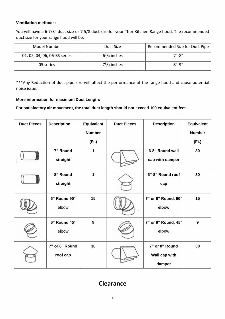
Ventilation methods:
You will have a 6 7/8" duct size or 7 5/8 duct size for your Thor Kitchen Range hood. The recommended
duct size for your range hood will be:
Model Number Duct Size Recommended Size for Duct Pipe
01, 02, 04, 06, 06-BS series 67/8 inches 7”-8”
05 series 75/8 inches 8”-9”
***Any Reduction of duct pipe size will affect the performance of the range hood and cause potential
noise issue.
More information for maximum Duct Length:
For satisfactory air movement, the total duct length should not exceed 100 equivalent feet.
Duct Pieces Description Equivalent
Number
(Ft.)
Duct Pieces Description Equivalent
Number
(Ft.)
7” Round
straight
1
6-8” Round wall
cap with damper
30
8” Round
straight
1
6”-8” Round roof
cap
30
6” Round 90°
elbow
15
7” or 8” Round, 90°
elbow
15
6” Round 45°
elbow
9
7” or 8” Round, 45°
elbow
9
7” or 8” Round
roof cap
30
7” or 8” Round
Wall cap with
damper
30
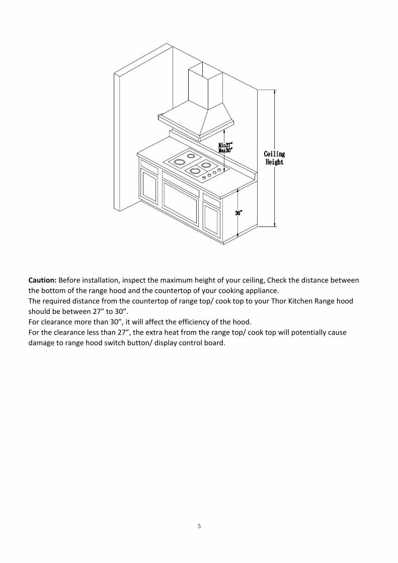
Clearance
5
Caution: Before installation, inspect the maximum height of your ceiling, Check the distance between
the bottom of the range hood and the countertop of your cooking appliance.
The required distance from the countertop of range top/ cook top to your Thor Kitchen Range hood
should be between 27” to 30”.
For clearance more than 30”, it will affect the efficiency of the hood.
For the clearance less than 27”, the extra heat from the range top/ cook top will potentially cause
damage to range hood switch button/ display control board.
6
Installation
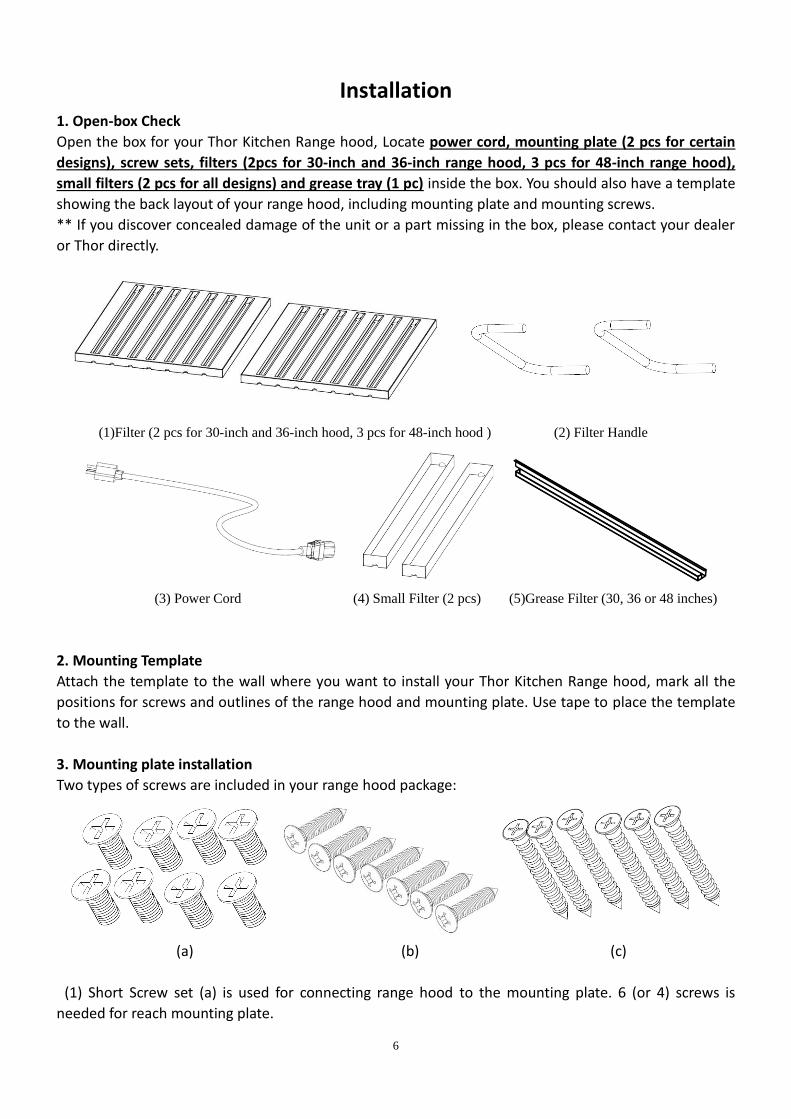
1. Open-box Check
Open the box for your Thor Kitchen Range hood, Locate power cord, mounting plate (2 pcs for certain
designs), screw sets, filters (2pcs for 30-inch and 36-inch range hood, 3 pcs for 48-inch range hood),
small filters (2 pcs for all designs) and grease tray (1 pc) inside the box. You should also have a template
showing the back layout of your range hood, including mounting plate and mounting screws.
** If you discover concealed damage of the unit or a part missing in the box, please contact your dealer
or Thor directly.
(1)Filter (2 pcs for 30-inch and 36-inch hood, 3 pcs for 48-inch hood ) (2) Filter Handle
(3) Power Cord (4) Small Filter (2 pcs) (5)Grease Filter (30, 36 or 48 inches)
2. Mounting Template
Attach the template to the wall where you want to install your Thor Kitchen Range hood, mark all the
positions for screws and outlines of the range hood and mounting plate. Use tape to place the template
to the wall.
3. Mounting plate installation
Two types of screws are included in your range hood package:
(a) (b) (c)
(1) Short Screw set (a) is used for connecting range hood to the mounting plate. 6 (or 4) screws is
needed for reach mounting plate.
7
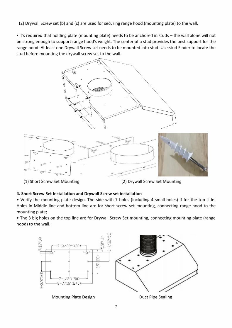
(2) Drywall Screw set (b) and (c) are used for securing range hood (mounting plate) to the wall.
• It’s required that holding plate (mounting plate) needs to be anchored in studs – the wall alone will not
be strong enough to support range hood’s weight. The center of a stud provides the best support for the
range hood. At least one Drywall Screw set needs to be mounted into stud. Use stud Finder to locate the
stud before mounting the drywall screw set to the wall.
(1) Short Screw Set Mounting (2) Drywall Screw Set Mounting
4. Short Screw Set Installation and Drywall Screw set installation
• Verify the mounting plate design. The side with 7 holes (including 4 small holes) if for the top side.
Holes in Middle line and bottom line are for short screw set mounting, connecting range hood to the
mounting plate;
• The 3 big holes on the top line are for Drywall Screw Set mounting, connecting mounting plate (range
hood) to the wall.
Mounting Plate Design Duct Pipe Sealing
8
5. Duct Pipe Sealing
Use duct sealing tape to connect duct pipe to the hood duct. Avoid reducing for the duct pipe size or it
will affect hood performance.
• We provide a 67/8 inches (in certain models 75/8 inches) duct size for your Thor Kitchen Range Hood.
Recommended duct size for your range hood is shown below:
Model Number Duct Size Recommended Size for Duct Pipe
01, 02, 04, 06, 06-BS series 67/8 inches 7”-8”
05 series 75/8 inches 8”-9”
6. Connect Power Cord to the range hood
• Locate the power cord in your range hood package, connect the power cord to your range hood power outlet
(located on the top rear right of the range hood)
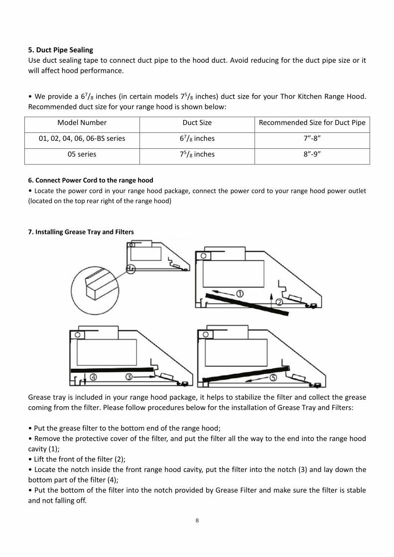
7. Installing Grease Tray and Filters
Grease tray is included in your range hood package, it helps to stabilize the filter and collect the grease
coming from the filter. Please follow procedures below for the installation of Grease Tray and Filters:
• Put the grease filter to the bottom end of the range hood;
• Remove the protective cover of the filter, and put the filter all the way to the end into the range hood
cavity (1);
• Lift the front of the filter (2);
• Locate the notch inside the front range hood cavity, put the filter into the notch (3) and lay down the
bottom part of the filter (4);
• Put the bottom of the filter into the notch provided by Grease Filter and make sure the filter is stable
and not falling off.
9
8. Filter handle Installation
Your Thor Kitchen Range Hood might have a KD design handle.
9. For Ceiling pipe
If the duct vents to the top ceiling:
• Use a pencil to draw a vertical line from the center of the template to the top ceiling;
• Make sure there’s at least 4” clearance from the back wall to the top ceiling where the hood duct is
located, and the size of the hood duct on top ceiling should be no less than 71/2” (81/2” for 05 series
range hood).
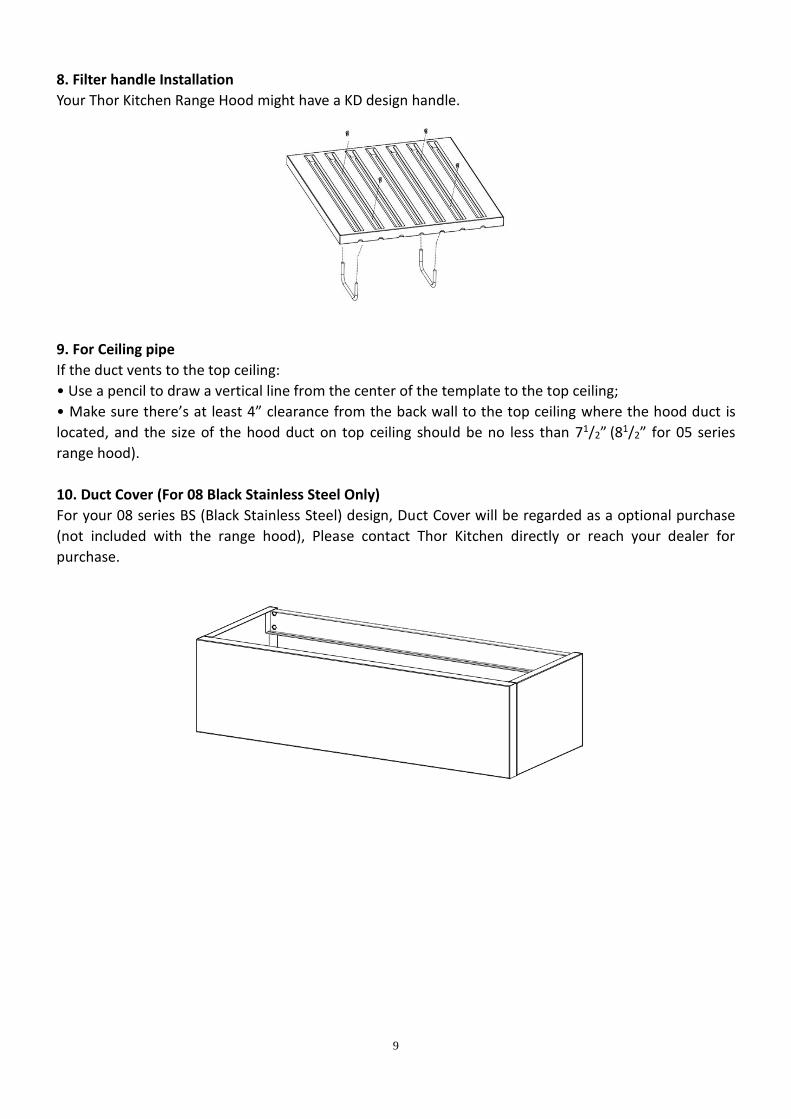
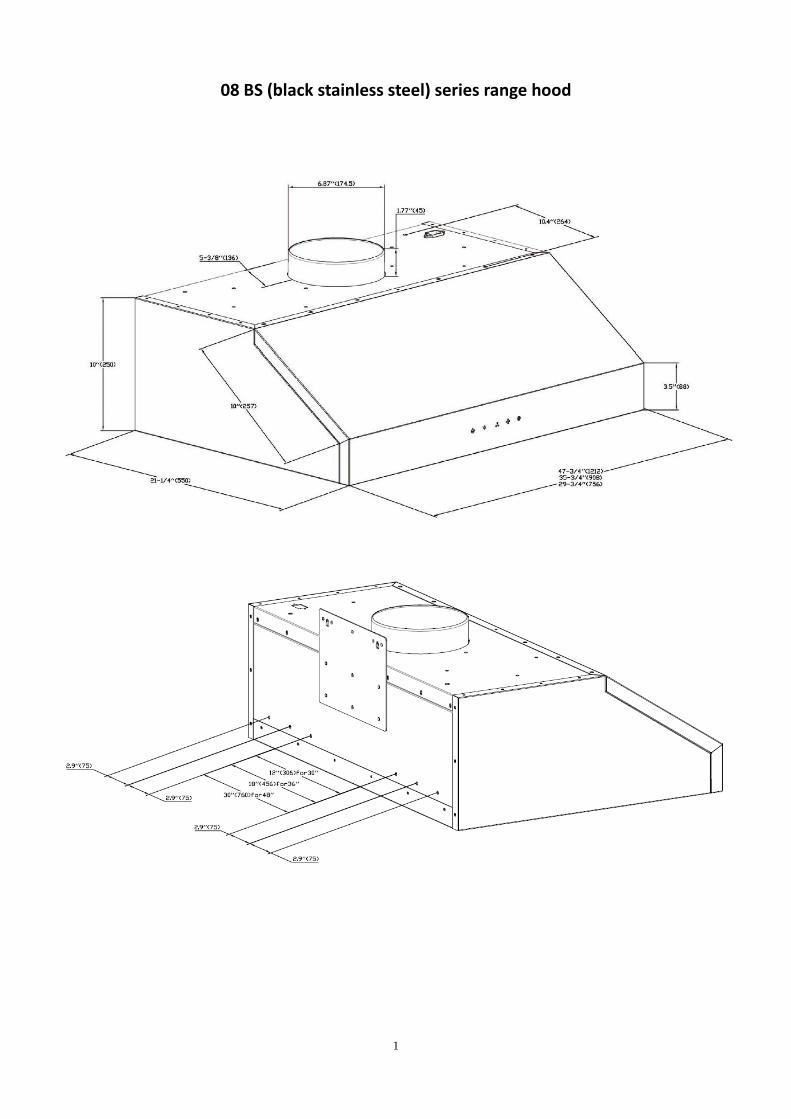
10. Duct Cover (For 08 Black Stainless Steel Only)
For your 08 series BS (Black Stainless Steel) design, Duct Cover will be regarded as a optional purchase
(not included with the range hood), Please contact Thor Kitchen directly or reach your dealer for
purchase.
10
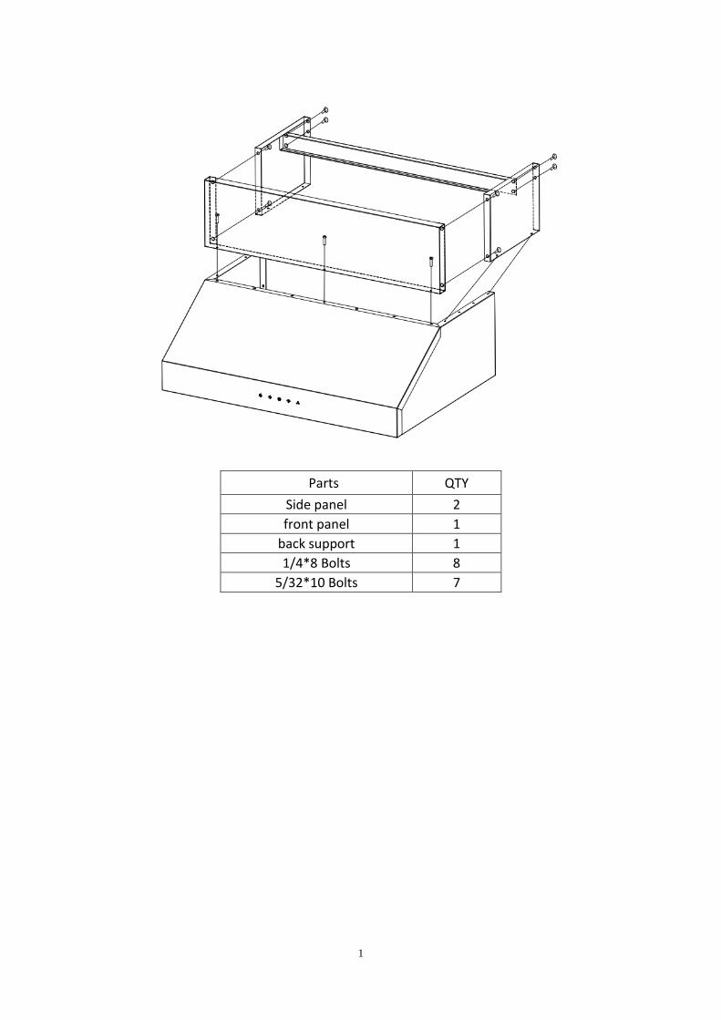
Parts QTY Side panel 2
front panel 1
back support 1
1/4*8 Bolts 8
5/32*10 Bolts 7
11
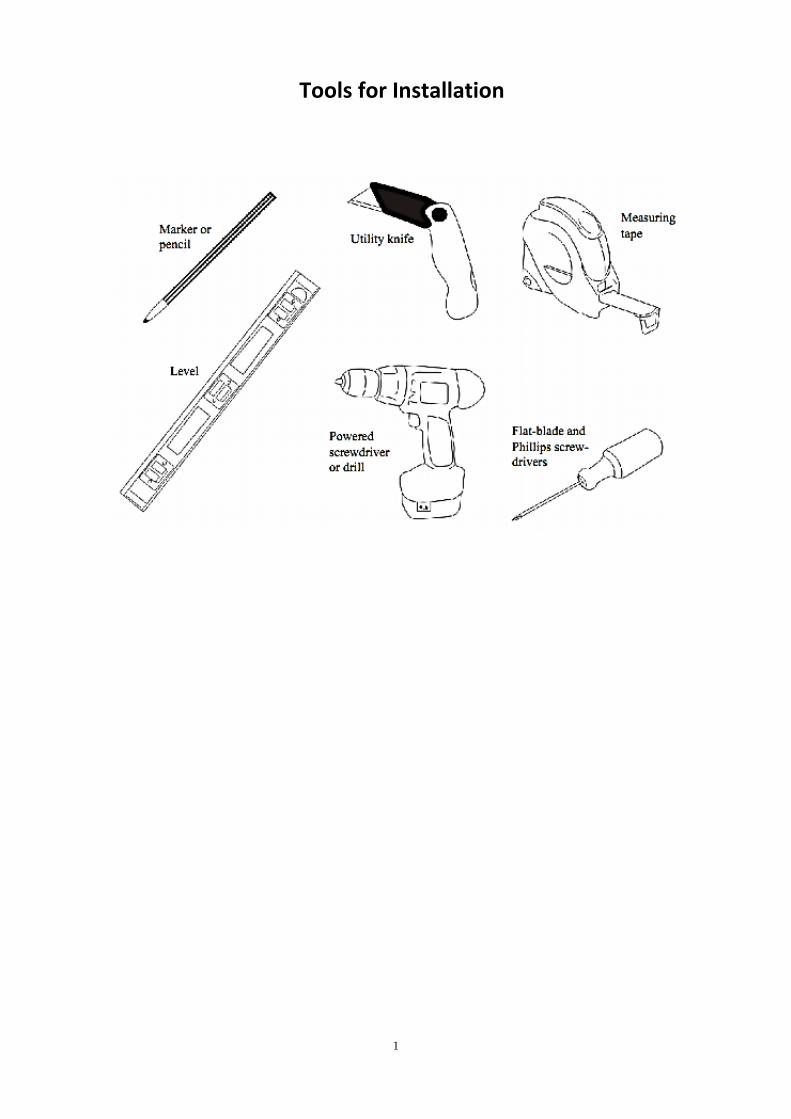
Tools for Installation
12
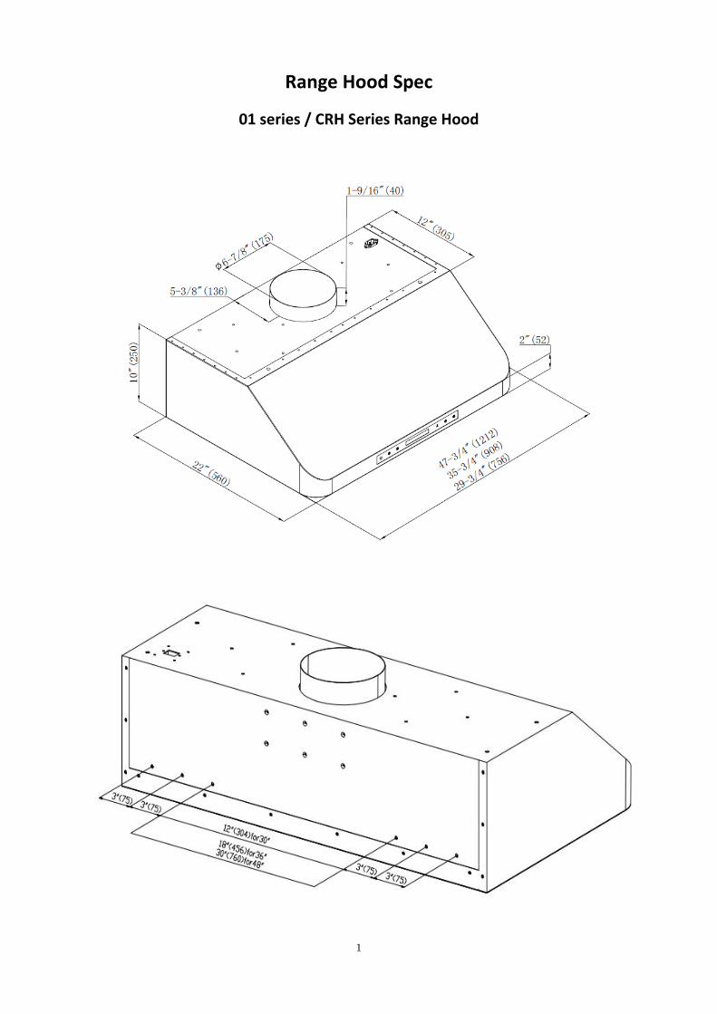
Range Hood Spec
01 series / CRH Series Range Hood
13
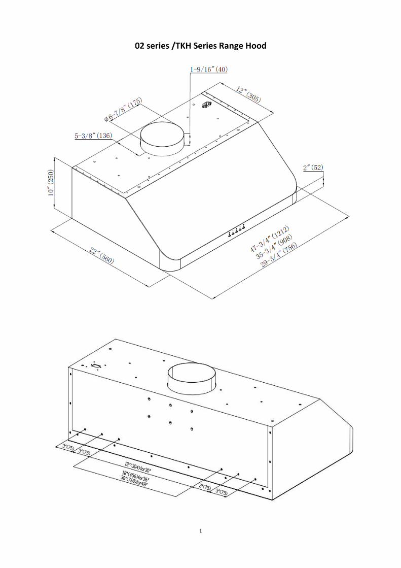
02 series /TKH Series Range Hood
14
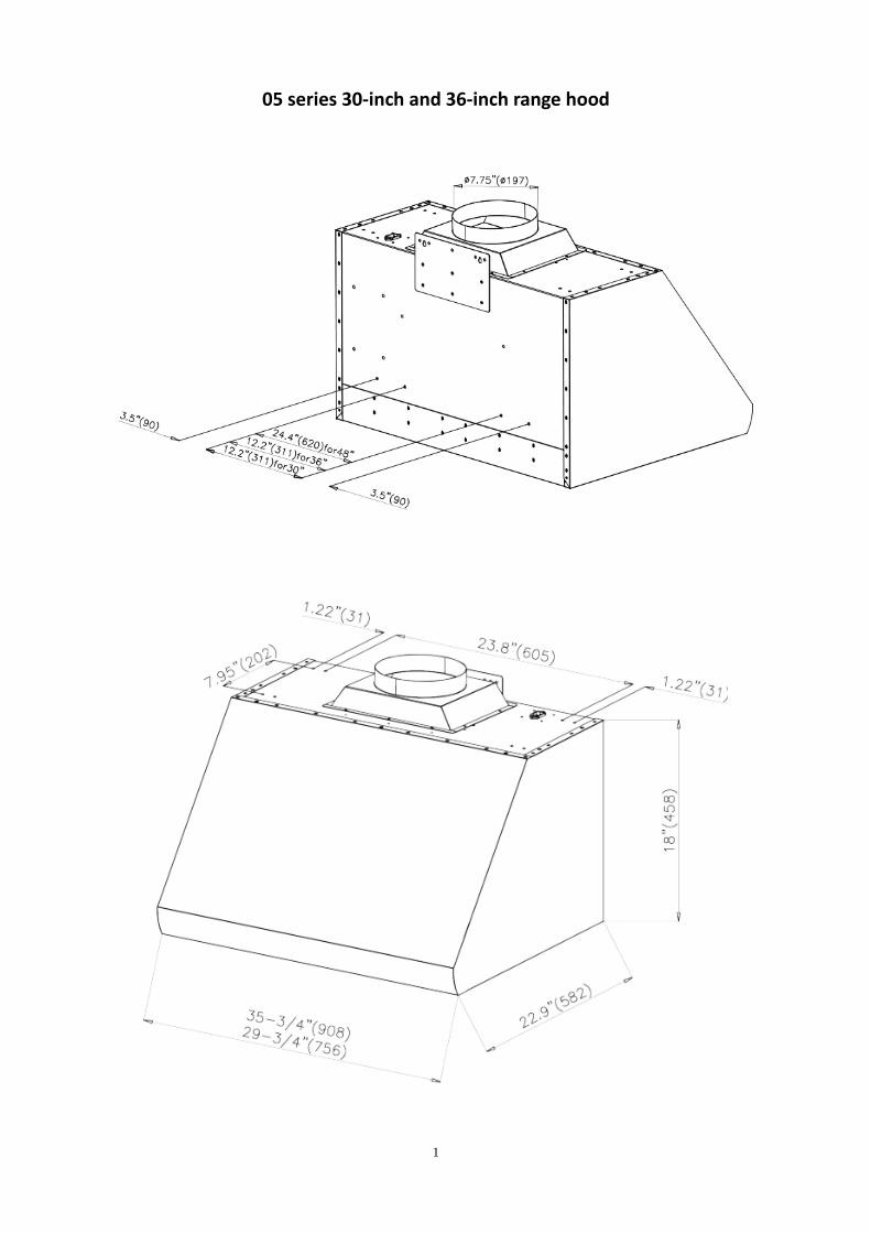
05 series 30-inch and 36-inch range hood
15
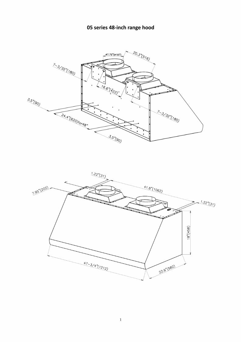
05 series 48-inch range hood
16
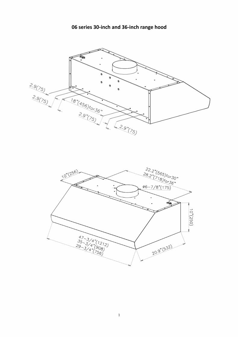
06 series 30-inch and 36-inch range hood
17
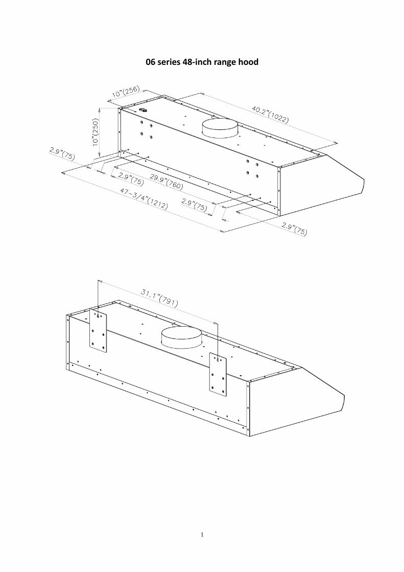
06 series 48-inch range hood
18
08 BS (black stainless steel) series range hood
19
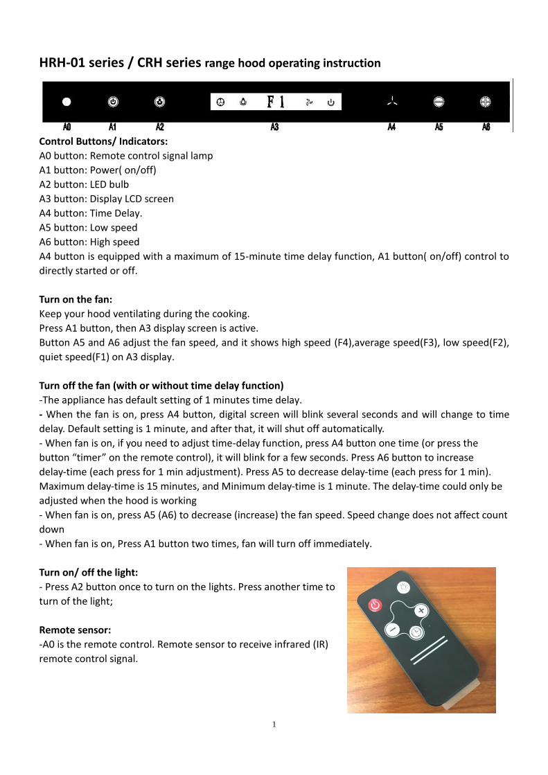
HRH-01 series / CRH series range hood operating instruction
Control Buttons/ Indicators:
A0 button: Remote control signal lamp
A1 button: Power( on/off)
A2 button: LED bulb
A3 button: Display LCD screen
A4 button: Time Delay.
A5 button: Low speed
A6 button: High speed
A4 button is equipped with a maximum of 15-minute time delay function, A1 button( on/off) control to
directly started or off.
Turn on the fan:
Keep your hood ventilating during the cooking.
Press A1 button, then A3 display screen is active.
Button A5 and A6 adjust the fan speed, and it shows high speed (F4),average speed(F3), low speed(F2),
quiet speed(F1) on A3 display.
Turn off the fan (with or without time delay function)
-The appliance has default setting of 1 minutes time delay.
- When the fan is on, press A4 button, digital screen will blink several seconds and will change to time
delay. Default setting is 1 minute, and after that, it will shut off automatically.
- When fan is on, if you need to adjust time-delay function, press A4 button one time (or press the
button “timer” on the remote control), it will blink for a few seconds. Press A6 button to increase
delay-time (each press for 1 min adjustment). Press A5 to decrease delay-time (each press for 1 min).
Maximum delay-time is 15 minutes, and Minimum delay-time is 1 minute. The delay-time could only be
adjusted when the hood is working
- When fan is on, press A5 (A6) to decrease (increase) the fan speed. Speed change does not affect count
down
- When fan is on, Press A1 button two times, fan will turn off immediately.
Turn on/ off the light:
- Press A2 button once to turn on the lights. Press another time to
turn of the light;
Remote sensor:
-A0 is the remote control. Remote sensor to receive infrared (IR)
remote control signal.
20
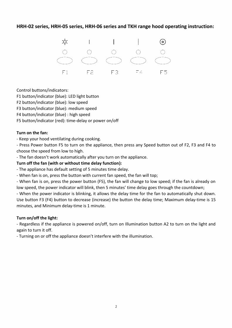
HRH-02 series, HRH-05 series, HRH-06 series and TKH range hood operating instruction:
Control buttons/indicators:
F1 button/indicator (blue): LED light button
F2 button/indicator (blue): low speed
F3 button/indicator (blue): medium speed
F4 button/indicator (blue) : high speed
F5 button/indicator (red): time-delay or power on/off
Turn on the fan:
- Keep your hood ventilating during cooking.
- Press Power button F5 to turn on the appliance, then press any Speed button out of F2, F3 and F4 to
choose the speed from low to high.
- The fan doesn’t work automatically after you turn on the appliance.
Turn off the fan (with or without time delay function):
- The appliance has default setting of 5 minutes time delay.
- When fan is on, press the button with current fan speed, the fan will top;
- When fan is on, press the power button (F5), the fan will change to low speed; if the fan is already on
low speed, the power indicator will blink, then 5 minutes’ time delay goes through the countdown;
- When the power indicator is blinking, it allows the delay time for the fan to automatically shut down.
Use button F3 (F4) button to decrease (increase) the button the delay time; Maximum delay-time is 15
minutes, and Minimum delay-time is 1 minute.
Turn on/off the light:
- Regardless if the appliance is powered on/off, turn on Illumination button A2 to turn on the light and
again to turn it off.
- Turning on or off the appliance doesn’t interfere with the illumination.
21
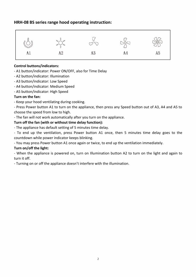
HRH-08 BS series range hood operating instruction:
Control buttons/indicators:
- A1 button/indicator: Power ON/OFF, also for Time Delay
- A2 button/indicator: Illumination
- A3 button/indicator: Low Speed
- A4 button/indicator: Medium Speed
- A5 button/indicator: High Speed
Turn on the fan:
- Keep your hood ventilating during cooking.
- Press Power button A1 to turn on the appliance, then press any Speed button out of A3, A4 and A5 to
choose the speed from low to high.
- The fan will not work automatically after you turn on the appliance.
Turn off the fan (with or without time delay function):
- The appliance has default setting of 5 minutes time delay.
- To end up the ventilation, press Power button A1 once, then 5 minutes time delay goes to the
countdown while power indicator keeps blinking.
- You may press Power button A1 once again or twice, to end up the ventilation immediately.
Turn on/off the light:
- When the appliance is powered on, turn on Illumination button A2 to turn on the light and again to
turn it off.
- Turning on or off the appliance doesn’t interfere with the illumination.
22
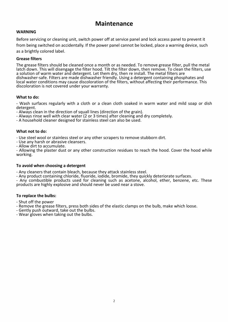
Maintenance WARNING
Before servicing or cleaning unit, switch power off at service panel and lock access panel to prevent it
from being switched on accidentally. If the power panel cannot be locked, place a warning device, such
as a brightly colored label.
Grease filters
The grease filters should be cleaned once a month or as needed. To remove grease filter, pull the metal latch down. This will disengage the filter hood. Tilt the filter down, then remove. To clean the filters, use a solution of warm water and detergent. Let them dry, then re install. The metal filters are dishwasher-safe. Filters are made dishwasher friendly. Using a detergent containing phosphates and local water conditions may cause discoloration of the filters, without affecting their performance. This discoloration is not covered under your warranty.
What to do:
- Wash surfaces regularly with a cloth or a clean cloth soaked in warm water and mild soap or dish detergent. - Always clean in the direction of squall lines (direction of the grain). - Always rinse well with clear water (2 or 3 times) after cleaning and dry completely. - A household cleaner designed for stainless steel can also be used.
What not to do:
- Use steel wool or stainless steel or any other scrapers to remove stubborn dirt. - Use any harsh or abrasive cleansers. - Allow dirt to accumulate. - Allowing the plaster dust or any other construction residues to reach the hood. Cover the hood while working.
To avoid when choosing a detergent
- Any cleaners that contain bleach, because they attack stainless steel. - Any product containing chloride, fluoride, iodide, bromide, they quickly deteriorate surfaces. - Any combustible products used for cleaning such as acetone, alcohol, ether, benzene, etc. These products are highly explosive and should never be used near a stove.
To replace the bulbs:
- Shut off the power - Remove the grease filters, press both sides of the elastic clamps on the bulb, make which loose. - Gently push outward, take out the bulbs. - Wear gloves when taking out the bulbs.
23
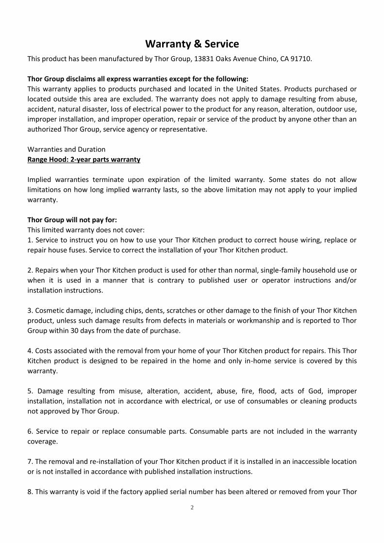
Warranty & Service This product has been manufactured by Thor Group, 13831 Oaks Avenue Chino, CA 91710.
Thor Group disclaims all express warranties except for the following:
This warranty applies to products purchased and located in the United States. Products purchased or
located outside this area are excluded. The warranty does not apply to damage resulting from abuse,
accident, natural disaster, loss of electrical power to the product for any reason, alteration, outdoor use,
improper installation, and improper operation, repair or service of the product by anyone other than an
authorized Thor Group, service agency or representative.
Warranties and Duration
Range Hood: 2-year parts warranty
Implied warranties terminate upon expiration of the limited warranty. Some states do not allow
limitations on how long implied warranty lasts, so the above limitation may not apply to your implied
warranty.
Thor Group will not pay for:
This limited warranty does not cover:
1. Service to instruct you on how to use your Thor Kitchen product to correct house wiring, replace or
repair house fuses. Service to correct the installation of your Thor Kitchen product.
2. Repairs when your Thor Kitchen product is used for other than normal, single-family household use or
when it is used in a manner that is contrary to published user or operator instructions and/or
installation instructions.
3. Cosmetic damage, including chips, dents, scratches or other damage to the finish of your Thor Kitchen
product, unless such damage results from defects in materials or workmanship and is reported to Thor
Group within 30 days from the date of purchase.
4. Costs associated with the removal from your home of your Thor Kitchen product for repairs. This Thor
Kitchen product is designed to be repaired in the home and only in-home service is covered by this
warranty.
5. Damage resulting from misuse, alteration, accident, abuse, fire, flood, acts of God, improper
installation, installation not in accordance with electrical, or use of consumables or cleaning products
not approved by Thor Group.
6. Service to repair or replace consumable parts. Consumable parts are not included in the warranty
coverage.
7. The removal and re-installation of your Thor Kitchen product if it is installed in an inaccessible location
or is not installed in accordance with published installation instructions.
8. This warranty is void if the factory applied serial number has been altered or removed from your Thor
24
Kitchen product.
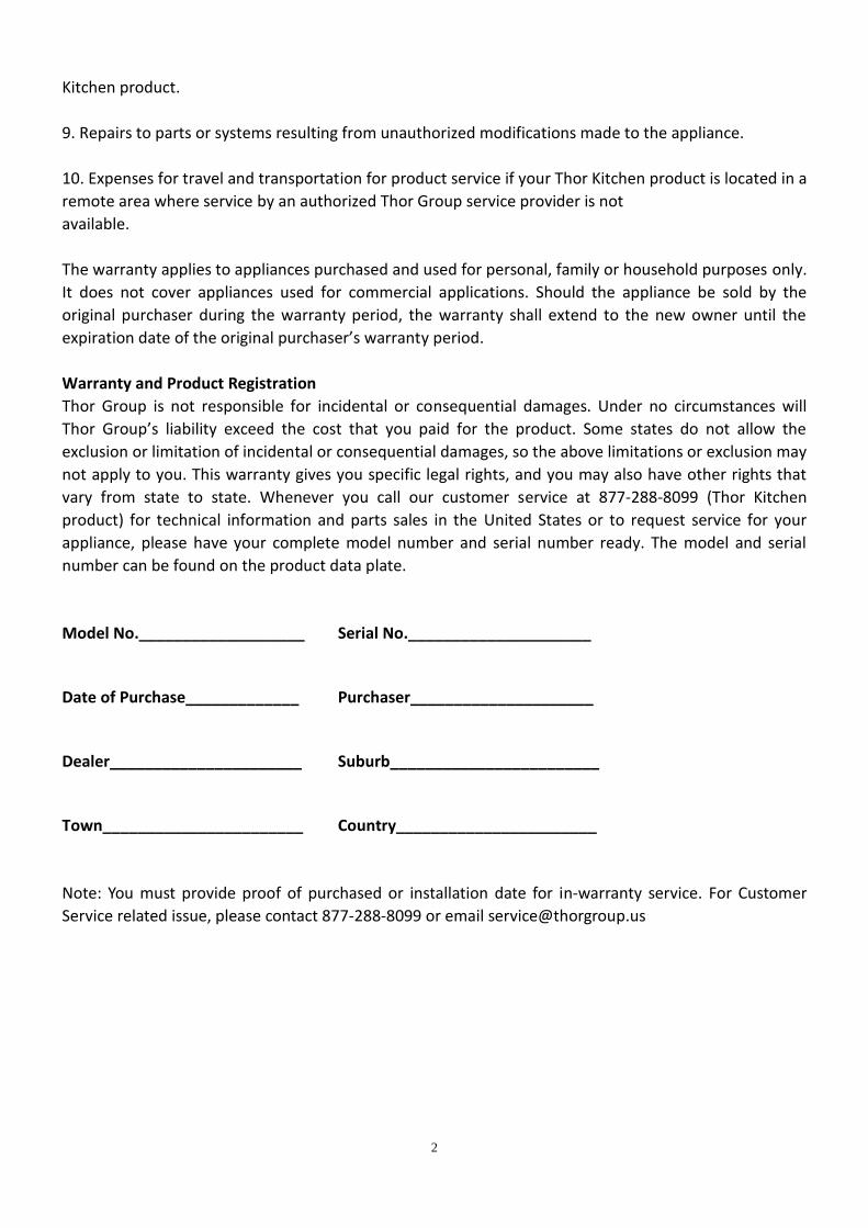
9. Repairs to parts or systems resulting from unauthorized modifications made to the appliance.
10. Expenses for travel and transportation for product service if your Thor Kitchen product is located in a
remote area where service by an authorized Thor Group service provider is not
available.
The warranty applies to appliances purchased and used for personal, family or household purposes only.
It does not cover appliances used for commercial applications. Should the appliance be sold by the
original purchaser during the warranty period, the warranty shall extend to the new owner until the
expiration date of the original purchaser’s warranty period.
Warranty and Product Registration
Thor Group is not responsible for incidental or consequential damages. Under no circumstances will
Thor Group’s liability exceed the cost that you paid for the product. Some states do not allow the
exclusion or limitation of incidental or consequential damages, so the above limitations or exclusion may
not apply to you. This warranty gives you specific legal rights, and you may also have other rights that
vary from state to state. Whenever you call our customer service at 877-288-8099 (Thor Kitchen
product) for technical information and parts sales in the United States or to request service for your
appliance, please have your complete model number and serial number ready. The model and serial
number can be found on the product data plate.
Model No.___________________ Serial No._____________________ Date of Purchase_____________ Purchaser_____________________ Dealer______________________ Suburb________________________ Town_______________________ Country_______________________
Note: You must provide proof of purchased or installation date for in-warranty service. For Customer
Service related issue, please contact 877-288-8099 or email [email protected]