Embed Size (px)
Citation preview
TechnicalInformation
Range-free Multi-controllerFA-M3R Overview
TI 34M6A01-01EFeb. 2009, 3rd EditionYokogawa Electric Corporation
www.yokogawa.com/itc/
Information in this document is current as of Feb. 2009.For the latest product information, contact Yokogawa sales office.
This document does not include detailed description of the latest F3SP66-4S and F3SP67-6S Sequence CPU Modules (with network functions).See “Sequence CPU Module (with network functions): New Product Introduction” (TI34M6A08-01E) instead.
ITI 34M6A01-01E
Contents
Introduction to FA-M3R .................................................................................................................. 1
FA-M3R Features............................................................................................................................. 2
Ultra-fast Processing Speed.......................................................................................................... 3
Comparison with Competitors ...................................................................................................... 4
Postcard-sized Controller .............................................................................................................. 5
Universal I/O Range Achievable with One PLC ........................................................................... 6
Mixed Installation of Different CPUs within One Unit ................................................................. 7
Sequence CPU Modules ............................................................................................................. 8
(F3SP08-SP, F3SP21-0N, F3SP28-3S, F3SP38-6S, F3SP53-4S, F3SP58-6S, F3SP59-7S,
F3SP66-4S, F3SP67-6S)
BASIC CPU Modules................................................................................................................... 9
(F3BP20-0N, F3BP30-0N, SF560-ECW)
Easy Real-time Processing with BASIC .................................................................................... 10
FA-M3 Value 2........................................................................................................................... 11
(F3SC23-1A, F3SC23-1F, F3SC23-2F)
FA-M3R Programming Tools
FA-M3R Programming Tool WideField2 (SF620-MCW)
Ladder Programming Tool Designed for Engineers............................................................. 12
Object Ladder ....................................................................................................................... 13
Structure ............................................................................................................................... 14
Input Macro........................................................................................................................... 16
Indirect Specification ............................................................................................................ 17
Downloading Comments ...................................................................................................... 18
Program Component ............................................................................................................ 19
Index View ............................................................................................................................ 20
Collective Change of I/O Positions....................................................................................... 21
Logical Design by Tag Name ............................................................................................... 22
Group Tag Name.................................................................................................................. 23
Flexible Find Function .......................................................................................................... 24
Advantages of Windows Environment.................................................................................. 25
Flexible Operability ............................................................................................................... 26
Sophisticated Debugging Functions..................................................................................... 27
Enriched Help Provides Convenient Help Information......................................................... 28
System Log........................................................................................................................... 29
User log ................................................................................................................................ 30
Sampling Trace .................................................................................................................... 31

IITI 34M6A01-01E
Remote OME in Your Preferred Way........................................................................................... 32
Remote OME by E-mail via Internet..................................................................................... 33
Remote OME via Ethernet Network ..................................................................................... 36
Remote OME via Public Telephone Line using Analog Modem .......................................... 38
Advanced Function Modules
Analog Input/Output Modules ....................................................................................................39
(F3AD04-0 , F3AD08- V, F3AD08- R, F3DA02-0N, F3DA04-1N, F3DA08-5N)
High-speed Data Acquisition Module ........................................................................................ 40
(F3HA08-0N)
Memory Card Module ................................................................................................................ 41
(F3EM01-0N)
Temperature Control/PID Modules............................................................................................ 42
(F3CU04-0S, F3CU04-1S)
Temperature Monitoring Module ............................................................................................... 43
(F3CX04-0N)
Positioning Modules................................................................................................................... 44
Positioning Modules for Controlling Every Type of Motor
Positioning Modules with Pulse Output
(F3NC32-0N, F3NC34-0N)
Positioning Modules with Analog Voltage Output
(F3NC51-0N, F3NC52-0N)
Positioning Modules with Multi-channel Pulse Output
(F3YP14-0N, F3YP18-0N)
Positioning Module with MECHATROLINK-II Interface
(F3NC96-0N)
ToolBox Software for Advanced Function Modules ................................................................. 48
ToolBox for Temperature Control and Monitoring Modules (SF661-ECW)
ToolBox for Positioning Modules (SF662-ECW)
Communications Information Network
Ethernet Interface Module ......................................................................................................... 51
(F3LE01-5T, F3LE11-0T, F3LE12-0T)
NX Interface Module .................................................................................................................. 52
(F3NX01-0N)
Control Network
FL-net (OPCN-2) Interface Module ........................................................................................... 53
(F3LX02-1N)
FA Link H Module ...................................................................................................................... 54
(F3LP02-0N)
IIITI 34M6A01-01E
Field Network
Fiber-optic FA-bus Module ........................................................................................................ 55
(F3LR01-0N)
Fiber-optic FA-bus Type 2 Module ............................................................................................ 56
(F3LR02-0N)
DeviceNet Interface Module ...................................................................................................... 57
(F3LD01-0N)
YHLS Master Module and Slave Units ...................................................................................... 58
(F3LH01-1N, F3LH02-1N, TAH Series)
Peripheral Modules Applications of Personal Computer Link Interface .................................................................. 59
(Connecting personal computer/display)
Personal Computer Link Modules ............................................................................................. 60
(F3LC11-1F, F3LC12-1F, F3LC11-2F)
Personal Computer Link via Programming Port ........................................................................ 61
UT Link Module (for connecting temperature controllers and recorders from Yokogawa) ....... 62
(F3LC51-2N)
GP-IB Communication Module (for connecting GP-IB instruments) ......................................... 63
(F3GB01-0N)
RS-232-C and RS-422/485 Communication Modules ..............................................................64
(F3RZ81-0F, F3RZ82-0F, F3RZ91-0F, F3RS22-0N, F3RS41-0N)
Terminal Block Units.......................................................................................................... 66
FA-M3R I/O Open Concept Allows FA-M3R-Compatible User I/O Modules .................. 67
Reduced Wiring System .................................................................................................... 68
1TI 34M6A01-01E
- FA-M3R is the new generic name for FA-M3 controllers installed with one or moreof the ultra-fast CPU modules.
- FA-M3R can simply be called the "M3R".- FA-M3R and FA-M3 are upward compatible.
From EVOLUTION to REVOLUTION
The FA-M3 has reborned as the FA-M3R, to revolutionize users' equipment.
for Revolution!
Range-free Controller FA-M3RTransforms user “Machine” into “M@chine”.
Introduction to FA-M3R
Transforms Equipment Using IT
2TI 34M6A01-01E
Ultra-fast Processing Speed- 20K steps of ladder program scanned per millisecond*
- Minimum scan time of 200 µs- Sensor control function with constant scan from 200 µs- Quick response from input to output of 10 µs - Quick response of 100 µs to an interrupt signal
Postcard-size Controller- Compact, 147 (W) x 100 (H) x 88 (D) mm size handles
192 points.
Universal I/O Range Achievable with One PLC - Controls up to 8,192 points and contain devices of up to
344K words per system.- Capabilities of a high-end PLC at the cost of a low- or
mid-range PLC- One third to one half the price of competitors’ PLC for
1000- to 2000-point range
Mixed Installation of Different CPUs within 1 Unit- Tasks can be divided among multiple ladder CPUs- Data processing using BASIC CPU
FA-M3R Programming Tool WideField2- Object ladder, a new programming paradigm after structured
programming- Structure facilitates data reuse.- Program componentization using Indirect specification and
input macro instructions- Circuit comments/subcomments and tag name definitions can
be stored in CPU to speed up maintenance.- Partial download increases debugging efficiency- Blocks and macros can be coded independently, thus
dramatically increasing reusability.- Improved visibility increases efficiency of reuse- Easy data exchange with Windows-based applications- System logs and user logs for troubleshooting- Sampling trace for troubleshooting
Remote OME** in Your Preferred Way- Remote OME by E-mail via Internet- Remote OME via Ethernet network- Remote OME via public telephone line and analog modem
FA-M3R Features
* These figures indicate the performance when running a program with typical ratio of basic instructions to application instructions. Not all user programs are guaranteed to run at this speed.
** Acronym of remote Operation Maintenance and Engineering proposed by Yokogawa Electric Corporation.
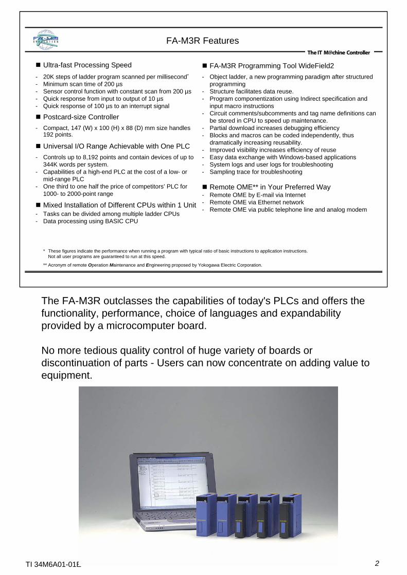
The FA-M3R outclasses the capabilities of today's PLCs and offers the functionality, performance, choice of languages and expandability provided by a microcomputer board.
No more tedious quality control of huge variety of boards or discontinuation of parts - Users can now concentrate on adding value to equipment.
3TI 34M6A01-01E
Ultra-fast Processing Speed
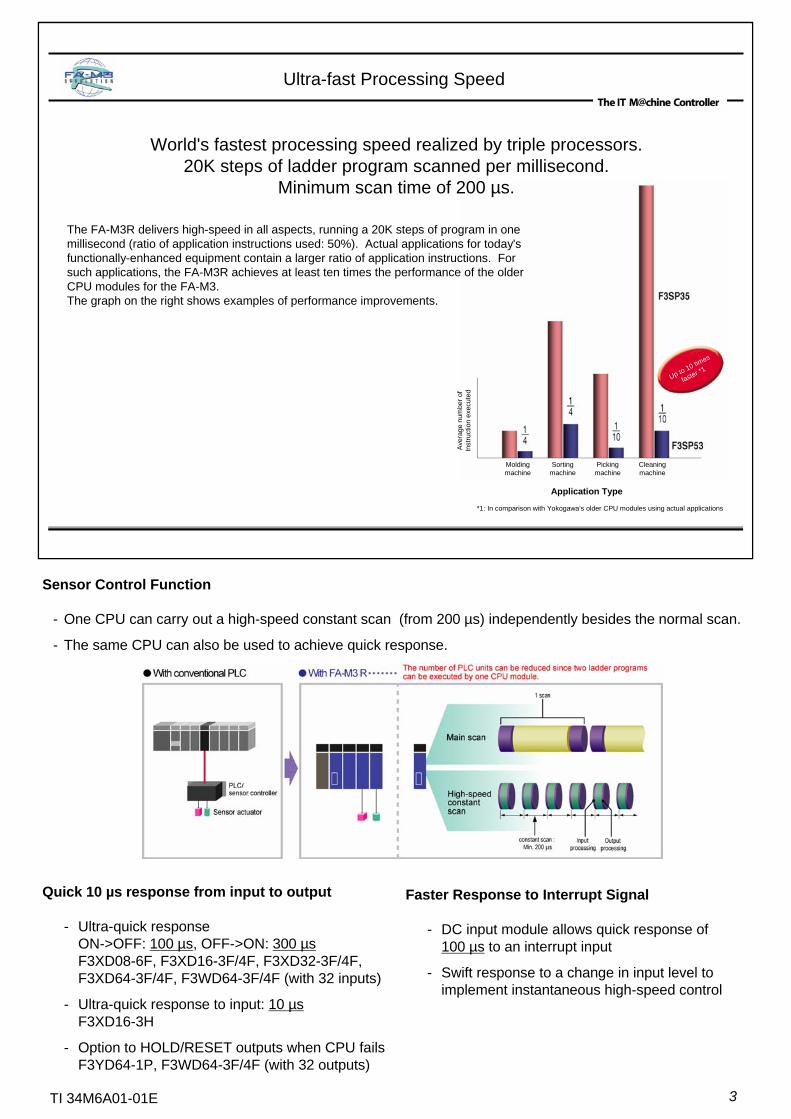
World's fastest processing speed realized by triple processors.20K steps of ladder program scanned per millisecond.
Minimum scan time of 200 µs.
The FA-M3R delivers high-speed in all aspects, running a 20K steps of program in one millisecond (ratio of application instructions used: 50%). Actual applications for today's functionally-enhanced equipment contain a larger ratio of application instructions. For such applications, the FA-M3R achieves at least ten times the performance of the older CPU modules for the FA-M3.The graph on the right shows examples of performance improvements.
*1: In comparison with Yokogawa’s older CPU modules using actual applications
Molding machine
Sortingmachine
Pickingmachine
Cleaningmachine
Aver
age
num
ber o
fIn
stru
ctio
n ex
ecut
ed
Application Type
Up to 10 times
faster *1
Quick 10 µs response from input to output
- Ultra-quick responseON->OFF: 100 µs, OFF->ON: 300 µsF3XD08-6F, F3XD16-3F/4F, F3XD32-3F/4F,F3XD64-3F/4F, F3WD64-3F/4F (with 32 inputs)
- Ultra-quick response to input: 10 µsF3XD16-3H
- Option to HOLD/RESET outputs when CPU failsF3YD64-1P, F3WD64-3F/4F (with 32 outputs)
Faster Response to Interrupt Signal
- DC input module allows quick response of 100 µs to an interrupt input
- Swift response to a change in input level toimplement instantaneous high-speed control
Sensor Control Function
- One CPU can carry out a high-speed constant scan (from 200 µs) independently besides the normal scan.
- The same CPU can also be used to achieve quick response.
4TI 34M6A01-01E
Comparison with Competitors
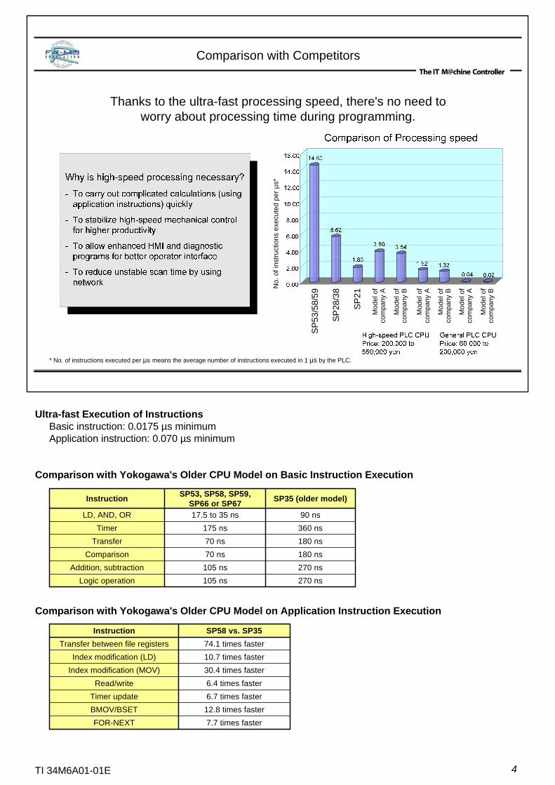
Thanks to the ultra-fast processing speed, there's no need to worry about processing time during programming.
* No. of instructions executed per µs means the average number of instructions executed in 1 µs by the PLC.
No.
of i
nstru
ctio
ns e
xecu
ted
per µ
s*
SP2
1
SP5
3/58
/59
SP28
/38
Mod
el o
f co
mpa
ny B
Mod
el o
f co
mpa
ny A
Mod
el o
f co
mpa
ny B
Mod
el o
f co
mpa
ny A
Mod
el o
f co
mpa
ny B
Mod
el o
f co
mpa
ny A
Ultra-fast Execution of InstructionsBasic instruction: 0.0175 µs minimumApplication instruction: 0.070 µs minimum
Comparison with Yokogawa's Older CPU Model on Application Instruction Execution
Comparison with Yokogawa's Older CPU Model on Basic Instruction Execution
270 ns105 nsLogic operation270 ns105 nsAddition, subtraction180 ns70 nsComparison180 ns70 nsTransfer360 ns175 nsTimer90 ns17.5 to 35 nsLD, AND, OR
SP35 (older model)SP53, SP58, SP59, SP66 or SP67Instruction
7.7 times fasterFOR-NEXT12.8 times fasterBMOV/BSET6.7 times fasterTimer update6.4 times fasterRead/write
30.4 times fasterIndex modification (MOV)10.7 times fasterIndex modification (LD)74.1 times fasterTransfer between file registersSP58 vs. SP35Instruction
5TI 34M6A01-01E
Postcard-sized Controller
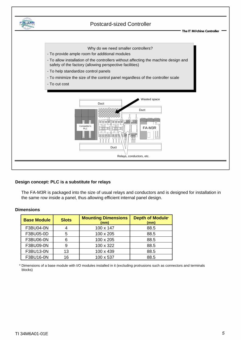
Why do we need smaller controllers?- To provide ample room for additional modules- To allow installation of the controllers without affecting the machine design and
safety of the factory (allowing perspective facilities)- To help standardize control panels- To minimize the size of the control panel regardless of the controller scale- To cut cost
Duct
Duct
Duct
Relays, conductors, etc.
Wasted space
Competitor’sPLC FA-M3R
Design concept: PLC is a substitute for relays
The FA-M3R is packaged into the size of usual relays and conductors and is designed for installation in the same row inside a panel, thus allowing efficient internal panel design.
* Dimensions of a base module with I/O modules installed in it (excluding protrusions such as connectors and terminals blocks)
Dimensions
88.5100 x 2055F3BU05-0D
88.5100 x 53716F3BU16-0N88.5100 x 43913F3BU13-0N88.5100 x 3229F3BU09-0N88.5100 x 2056F3BU06-0N
88.5100 x 1474F3BU04-0N
Depth of Module*
(mm)Mounting Dimensions
(mm)SlotsBase Module
6TI 34M6A01-01E
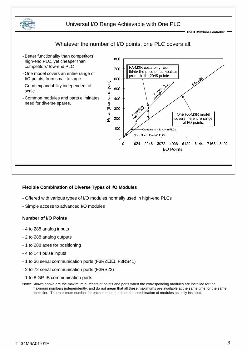
Whatever the number of I/O points, one PLC covers all.
Universal I/O Range Achievable with One PLC
- Better functionality than competitors’high-end PLC, yet cheaper than competitors’ low-end PLC
- One model covers an entire range of I/O points, from small to large
- Good expandability independent of scale
- Common modules and parts eliminates need for diverse spares.
Flexible Combination of Diverse Types of I/O Modules
- Offered with various types of I/O modules normally used in high-end PLCs
- Simple access to advanced I/O modules
Number of I/O Points
- 4 to 288 analog inputs
- 2 to 288 analog outputs
- 1 to 288 axes for positioning
- 4 to 144 pulse inputs
- 1 to 36 serial communication ports (F3RZ , F3RS41)
- 2 to 72 serial communication ports (F3RS22)
- 1 to 8 GP-IB communication ports Note: Shown above are the maximum numbers of points and ports when the corresponding modules are installed for the
maximum numbers independently, and do not mean that all these maximums are available at the same time for the same controller. The maximum number for each item depends on the combination of modules actually installed.

7TI 34M6A01-01E
-Use any programming language you like. -Use the optimal language for your applications. -Combine languages freely.
Mixed Installation of Different CPUs within One Unit
* Only one BASIC CPU module can be installed per controller.
- Any CPU can directly access I/O modules.- Different types of CPU modules can exchange data with each other.- A controller can comprise of a single CPU module or CPU modules of a single type.- FA-M3R (Sequence CPU or BASIC CPU) can be combined in a multi-CPU configuration.
Electrical and mechanical engineers may prefer a ladder diagram, while production engineers may prefer BASIC.
The FA-M3R allows free choice of CPUs and programming languages to fit application needs.
Object ladder language 30K steps, 0.045 µs/basic instructionF3SP28-3S
YM-BASIC/FA language, 510KBF3BP30-0NYM-BASIC/FA language, 120KBF3BP20-0N
BASIC CPU Module
Object ladder 120K steps, 0.0175 µs/basic instruction, with network functionsF3SP67-6SObject ladder 56K steps, 0.0175 µs/basic instruction, with network functionsF3SP66-4SObject ladder language 254K steps, 0.0175 µs/basic instructionF3SP59-7SObject ladder language 120K steps, 0.0175 µs/basic instructionF3SP58-6SObject ladder language 56K steps, 0.0175 µs/basic instructionF3SP53-4SObject ladder language 120K steps, 0.045 µs/basic instruction F3SP38-6S
Sequence CPU module
Object ladder language 10K steps, 0.18 µs/basic instructionF3SP21-0NSpecificationsModelModule
All CPU types do not require replacement of the memory battery (maintenance free).The service life of this battery exceeds 10 years in standby mode at room temperature but may be shortened when exposed to extreme low or high temperatures.
8TI 34M6A01-01E
Sequence CPU Modules
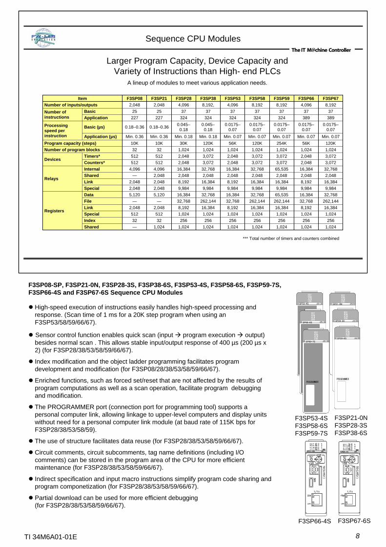
Larger Program Capacity, Device Capacity and Variety of Instructions than High- end PLCs
A lineup of modules to meet various application needs.
*** Total number of timers and counters combined
1,024 256
1,024 16,384 262,144 65,535 9,984 16,384 2,048 65,535 3,072 3,072 1,024 254K
Min. 0.07
0.0175–0.07
324 37
8,192 F3SP59
1,024 256
1,024 8,19232,76816,384 9,984 8,1922,048 16,384 2,048 2,048 1,024 56K
Min. 0.07
0.0175–0.07
389 37
4,096 F3SP66
1,024 256
1,024 16,384 262,144 32,768 9,984 16,384 2,048 32,768 3,072 3,072 1,024 120K
Min. 0.07
0.0175–0.07
389 37
8,192 F3SP67
1,0241,0241,0241,0241,024—Shared2562562562563232Index
1,0241,0241,0241,024512512Special16,3848,19216,3848,1922,0482,048Link262,14432,768262,14432,768——File32,76816,38432,76816,3845,1205,120Data
Registers
9,9849,9849,9849,9842,0482,048Special16,3848,19216,3848,1922,0482,048Link2,0482,0482,0482,0482,048—Shared32,76816,38432,76816,3844,0964,096Internal
Relays
3,0722,0483,0722,048512512Counters*3,0722,0483,0722,048512512Timers*
Devices
1,0241,0241,0241,0243232Number of program blocks120K56K120K30K10K10KProgram capacity (steps)
Min. 0.07Min. 0.07Min. 0.18Min. 0.18Min. 0.36Min. 0.36Application (µs)
0.0175–0.07
0.0175–0.07
0.045–0.18
0.045–0.180.18–0.360.18–0.36Basic (µs)Processing
speed per instruction
324324324324227227Application373737372525BasicNumber of
instructions
8,1924,0968,192,4,0962,0482,048Number of inputs/outputsF3SP58F3SP53F3SP38F3SP28F3SP21F3SP08Item
High-speed execution of instructions easily handles high-speed processing and response. (Scan time of 1 ms for a 20K step program when using an F3SP53/58/59/66/67).
Sensor control function enables quick scan (input program execution output) besides normal scan . This allows stable input/output response of 400 µs (200 µs x 2) (for F3SP28/38/53/58/59/66/67).
Index modification and the object ladder programming facilitates program development and modification (for F3SP08/28/38/53/58/59/66/67).
Enriched functions, such as forced set/reset that are not affected by the results of program computations as well as a scan operation, facilitate program debugging and modification.
The PROGRAMMER port (connection port for programming tool) supports a personal computer link, allowing linkage to upper-level computers and display units without need for a personal computer link module (at baud rate of 115K bps for F3SP28/38/53/58/59).
The use of structure facilitates data reuse (for F3SP28/38/53/58/59/66/67).
Circuit comments, circuit subcomments, tag name definitions (including I/O comments) can be stored in the program area of the CPU for more efficient maintenance (for F3SP28/38/53/58/59/66/67).
Indirect specification and input macro instructions simplify program code sharing and program componetization (for F3SP28/38/53/58/59/66/67).
Partial download can be used for more efficient debugging (for F3SP28/38/53/58/59/66/67).
F3SP08-SP, F3SP21-0N, F3SP28-3S, F3SP38-6S, F3SP53-4S, F3SP58-6S, F3SP59-7S, F3SP66-4S and F3SP67-6S Sequence CPU Modules
F3SP53-4SF3SP58-6SF3SP59-7S
F3SP21-0NF3SP28-3SF3SP38-6S
SIO
SIO
F3SP66-4S F3SP67-6S
RDYRUNALMERR
SP53-4S CPU
RDYRUNALMERR
SP21-0N CPU
RDYRUNALMERR
PROGRAMMER
SP28-3S CPU
RDYRUNALMERR
PROGRAMMER
SP38-6S CPU
RDYRUNALMERR
SP58-6S CPU
PROGRAMMER
RDYRUNALMERR
SP59-7S CPU
PROGRAMMER
RDYRUNALMERR
SP53-4S CPU
RDYRUNALMERR
SP53-4S CPU
RDYRUNALMERR
SP21-0N CPU
RDYRUNALMERR
PROGRAMMER
SP28-3S CPU
RDYRUNALMERR
PROGRAMMER
SP38-6S CPU
RDYRUNALMERR
SP21-0N CPU
RDYRUNALMERR
SP21-0N CPU
RDYRUNALMERR
PROGRAMMER
SP28-3S CPU
RDYRUNALMERR
PROGRAMMER
SP28-3S CPU
RDYRUNALMERR
PROGRAMMER
SP38-6S CPU
RDYRUNALMERR
PROGRAMMER
SP38-6S CPU
RDYRUNALMERR
SP58-6S CPU
PROGRAMMER
RDYRUNALMERR
SP58-6S CPU
RDYRUNALMERR
SP58-6S CPU
PROGRAMMER
RDYRUNALMERR
SP59-7S CPU
PROGRAMMER
RDYRUNALMERR
SP59-7S CPU
RDYRUNALMERR
SP59-7S CPU
PROGRAMMER
9TI 34M6A01-01E
BASIC CPU Modules
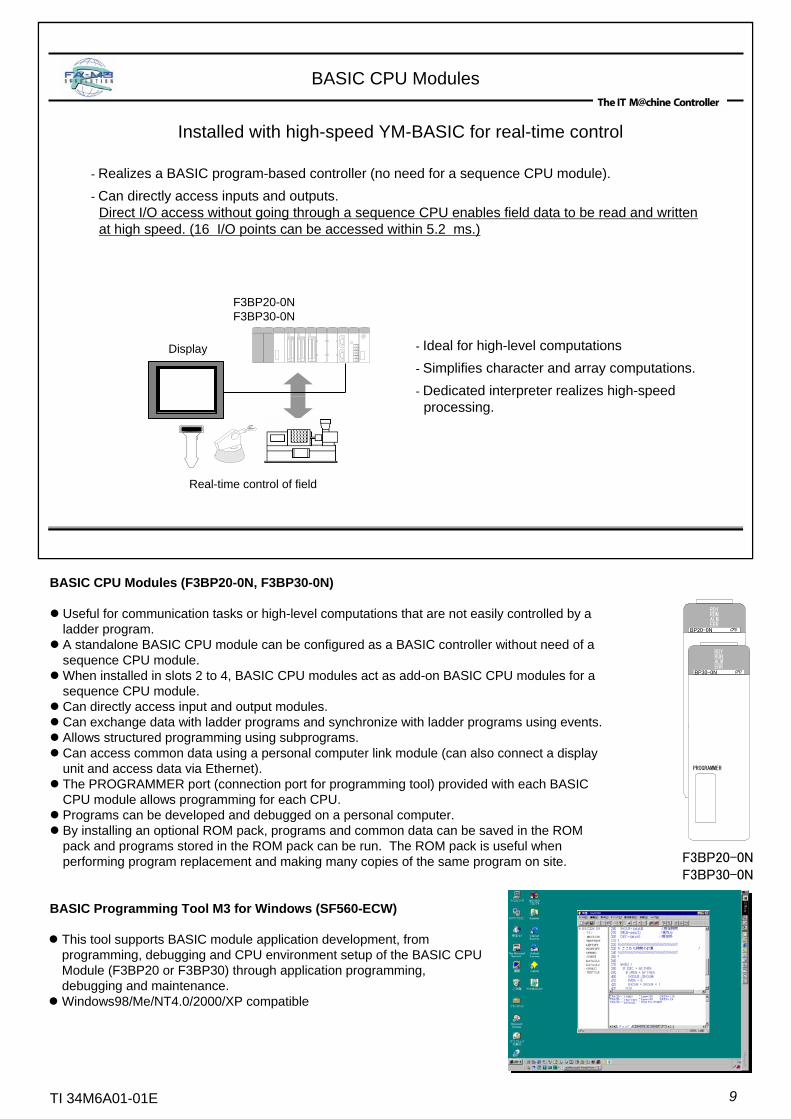
- Realizes a BASIC program-based controller (no need for a sequence CPU module).- Can directly access inputs and outputs.
Direct I/O access without going through a sequence CPU enables field data to be read and written at high speed. (16 I/O points can be accessed within 5.2 ms.)
- Ideal for high-level computations- Simplifies character and array computations.- Dedicated interpreter realizes high-speed
processing.
Installed with high-speed YM-BASIC for real-time control
F3BP20-0NF3BP30-0N
Real-time control of field
Display
BASIC CPU Modules (F3BP20-0N, F3BP30-0N)
Useful for communication tasks or high-level computations that are not easily controlled by a ladder program.A standalone BASIC CPU module can be configured as a BASIC controller without need of a sequence CPU module.When installed in slots 2 to 4, BASIC CPU modules act as add-on BASIC CPU modules for a sequence CPU module.Can directly access input and output modules.Can exchange data with ladder programs and synchronize with ladder programs using events.Allows structured programming using subprograms.Can access common data using a personal computer link module (can also connect a display unit and access data via Ethernet).The PROGRAMMER port (connection port for programming tool) provided with each BASIC CPU module allows programming for each CPU.Programs can be developed and debugged on a personal computer.By installing an optional ROM pack, programs and common data can be saved in the ROM pack and programs stored in the ROM pack can be run. The ROM pack is useful when performing program replacement and making many copies of the same program on site. F3BP20-0N
F3BP30-0N
RDYRUNALMERR
PROGRAMMER
BP20-0N CPU
RDYRUNALMERR
PROGRAMMER
BP30-0N CPU
This tool supports BASIC module application development, from programming, debugging and CPU environment setup of the BASIC CPU Module (F3BP20 or F3BP30) through application programming, debugging and maintenance.Windows98/Me/NT4.0/2000/XP compatible
BASIC Programming Tool M3 for Windows (SF560-ECW)

10TI 34M6A01-01E
Easy Real-time Processing with BASIC
Declaration of an interrupt routine needs only one statement.F3BP20-0N and F3BP30-0N
100 ON INT 2 , 5 GOSUB WARI@110 !120 LOOP@130.. Main routine.
140 GOTO LOOP@150 !160 WARI@170 !180 ENTER xxxxx Data input190 OUTPUT xxxxx Data output200 RETURN210 !220 STOP230 END
real-time BASIC,YM-BASIC/FA
Interrupt declaration
Interrupt routine
FA-M3R
Barcode Remote ID
Barcode reader
F3BP20-0NF3BP30-0N
YM-BASIC/FA
On-line real-time processing- Supports extensive interrupt methods to enable immediate response of a BASIC program to external
events.- Facilitates development of on-line real-time programs.
Modular program structure- Supports the use of subprograms.- Variables, line numbers and labels in the main and individual subprograms are independent. This
simplifies program development, maintenance and reuse.- The main program and subprograms can be developed separately, and combined later using the
APPEND command.Combination with sequence programs- Variables used in a BASIC program can be combined with shared registers simply using a common
variable statement, facilitating data exchange with sequence CPU modules. Synchronization with sequence CPU modules can also be achieved by using SIGNAL, ON SEQEVT, ENTER and OUTPUT statements.
- Device values in CPU modules can be read and written using ENTER and OUTPUT statements.I/O support- Can access various communication modules such as serial communication modules, various digital I/O
modules, and various analog I/O modules by using ENTER statements for input and OUTPUT statements for output.

11TI 34M6A01-01E
FA-M3 Value 2
FA-M3R's extensive functions and unrivaled performance available at an attractive price.Special sets of CPU, power supply and I/O modules are offered
at discounted prices as value packs.Each FA-M3 value2 pack (F3SC23-1A, F3SC23-1F or F3SC23-2F) is a compact controller composed of different modules:
F3SC23-1A comprises F3SP08-SP, F3BU04-0N, F3XD16-3F, F3YD14-5A. F3SC23-1F comprises F3SP08-SP, F3BU04-0N, F3WD32-3F.F3SC23-2F comprises F3SP08-SP, F3BU04-0N, F3WD64-3F.
14 transistor contacts (sink); rated voltage: 12-24 VDCF3YD14-5Aoutput module
16 DC voltage inputs (sink/source), rated voltage: 24 VDCF3XD16-3Finput module
16 transistor contacts (sink); rated voltage: 24 VDCOutput16 DC voltage inputs, rated voltage: 24 VDCInputF3WD32-3F
input/output module
32 transistor contacts (sink); rated voltage: 24 VDCOutput32 DC voltage inputs, rated voltage: 24 VDCInputF3WD64-3F
input/output module
The same as F3SP21-0NOthersMax.2048Number of I/O points10K steps (can be saved to a ROM)Program capacityBasic instructions:25 kinds; application instructions:227 kindsInstructionsStructured ladder, mnemonicProgramming language
Sequence CPU
The same as F3PU10-0SOthers5 V DC, 2.0 ARated output
100-240 V AC, single phase, 50/60 HzInput power supply voltagePower
supply unit
F3SP08-SP sequence CPU module
4 (available spare I/O slots: 2)Number of slotsF3BU04-0N base module
SpecificationItem
FA-M3 Value 2 packs (F3SC23-1A, F3SC23-1F and F3SC23-2F)
Ultra-compact for space saving inside the panel.The sequence CPU module can receive universal power supply voltage ranging from 100 to 240 V AC, so the power supply need not be considered.High-speed execution of instructions facilitates development of applications requiring fast response.
Installing an optional ROM pack allows programs and data to be saved.
F3SC23-2F
PROGRAMMER
CPUSP08-SP
RUN RDY
RUN
14 91317212529261014182216303711151923273148121620242832
WD64-3F
DISPLAYDC IN
1 2
12TI 34M6A01-01E
System Design
Program Design
Programming
Debugging
Running
WideField2 greatly reduces the timerequired for these
processes.
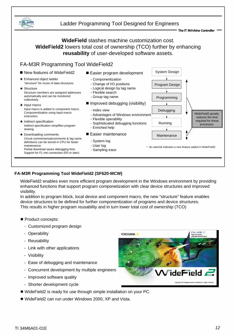
New features of WideField2★ Enhanced object ladder
“structure” for reuse of data structures
★ StructureStructure members are assigned addresses automatically and can be monitored collectively.
★ Input macroInput macro is added to component macro. Componentization using input macro instruction.
★ Indirect specificationIndirect specification simplifies program sharing
★ Downloading commentsCircuit comments/subcomments & tag name definitions can be stored in CPU for faster maintenance.Partial download saves debugging time.Support for FL-net connection (R3 or later)
Easier program development- Componentization- Change of I/O positions- Logical design by tag name- Flexible search- Group tag name
Improved debugging (visibility)- Index view- Advantages of Windows environment- Flexible operability- Sophisticated debugging functions- Enriched help
Easier maintenance- System log- User log- Sampling trace
Maintenance
FA-M3R Programming Tool WideField2
WideField slashes machine customization cost. WideField2 lowers total cost of ownership (TCO) further by enhancing
reusability of user-developed software assets.
Ladder Programming Tool Designed for Engineers
* An asterisk indicates a new feature added in WideField2.
FA-M3R Programming Tool WideField2 (SF620-MCW)
WideField2 enables even more efficient program development in the Windows environment by providing enhanced functions that support program componetization with clear device structures and improved visibility.In addition to program block, local device and component macro, the new “structure” feature enables device structures to be defined for further componentization of programs and device structures. This results in higher program reusability and in turn lower total cost of ownership (TCO)
Product concepts:- Customized program design
- Operability
- Reusability
- Link with other applications
- Visibility
- Ease of debugging and maintenance
- Concurrent development by multiple engineers
- Improved software quality
- Shorter development cycle
WideField2 is ready for use through simple installation on your PC.
WideField2 can run under Windows 2000, XP and Vista.

13TI 34M6A01-01E
Object Ladder
The FA-M3R Programming Tool WideField2 is a revolutionary application for object ladder programming − a successor of structured ladder programming in program development.In object ladder programming, program code for a function unit and its related devices are combined in an object called a block. Blocks are then combined to form a ladder program. Each block is functionally independent, thus improving productivity and program maintainability over and above structured programming*.Object ladder code is highly reusable. When customizing an existing machine control program for a user, the details of each block need not be checked; blocks are simply added or replaced.
*Structured programming is a programming method proposed by Yokogawa Electric Corporation in 1989, whereby a complex ladder program is divided into parts by functional unit so that developers can more easily understand the program structure, leading to improved productivity and program maintainability. Along with recognition of its advantages, use of structured programming grew rapidly in the 1990's as other PLC manufacturers rolled out products based on the same concept. Today structured programming is the de facto standard in PLC programming.
Conventional ladderprogramming
Structuredprogramming
Object ladderprogramming
1990 2000 Introduction of
“Structure”
Independent program blocks and data structures improve reusability
Conventional ladder(like a scroll)
Structured programming(like a file)
Program blocks are combined with data to create an application.
Object ladder
Program code and associated data are encapsulated within independent functional blocks, which are then combined to create an application.
Pro
gram
proc
essi
ng
Block A
DCB
Allows program code to be divided into blocks
Allows program code and data to be encapsulated within an independent block
Data
Block A
Program processing
DCB
Dat
a
14TI 34M6A01-01E
Structure
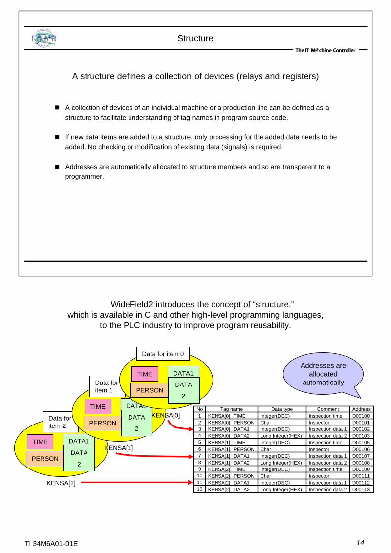
A collection of devices of an individual machine or a production line can be defined as a structure to facilitate understanding of tag names in program source code.
If new data items are added to a structure, only processing for the added data needs to be added. No checking or modification of existing data (signals) is required.
Addresses are automatically allocated to structure members and so are transparent to a programmer.
A structure defines a collection of devices (relays and registers)
TIME
PERSON
DATA1
DATA
2
Data for item 2
KENSA[2]
Addresses are allocated
automatically
TIME
PERSON
DATA1
DATA
2
Data for item 1
KENSA[1]
TIME
PERSON
DATA1
DATA
2
Data for item 0
KENSA[0]
WideField2 introduces the concept of “structure,”which is available in C and other high-level programming languages,
to the PLC industry to improve program reusability.
D00113Inspection data 2Long Integer(HEX)KENSA[2].DATA212D00112Inspection data 1Integer(DEC)KENSA[2].DATA111D00111InspectorCharKENSA[2].PERSON10D00100Inspection timeInteger(DEC)KENSA[2].TIME9D00108Inspection data 2Long Integer(HEX)KENSA[1].DATA28D00107Inspection data 1Integer(DEC)KENSA[1].DATA17D00106InspectorCharKENSA[1].PERSON6D00105Inspection timeInteger(DEC)KENSA[1].TIME5D00103Inspection data 2Long Integer(HEX)KENSA[0].DATA24D00102Inspection data 1Integer(DEC)KENSA[0].DATA13D00101InspectorCharKENSA[0].PERSON2D00100Inspection timeInteger(DEC)KENSA[0].TIME1AddressCommentData typeTag nameNo
15TI 34M6A01-01E
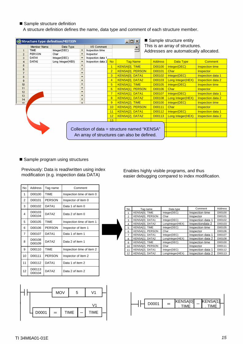
Sample structure definitionA structure definition defines the name, data type and comment of each structure member.
Sample structure entityThis is an array of structures.Addresses are automatically allocated.
Enables highly visible programs, and thuseasier debugging compared to index modification.
Previously: Data is read/written using index modification (e.g. inspection data DATA)
TIME=D0001
V15MOV
V1
- TIME
KENSA[0].TIME=D0001 -
KENSA[1].TIME
Sample program using structures
Data 2 of item 2DATA2D00113 D0010412
Data 1 of item 2DATA1D0011211
Inspector of item 2PERSOND0011110
Inspection time of item 2TIMED001109
Data 2 of item 1DATA2D00108 D001098
Data 1 of item 1DATA1D001077
Inspector of item 1PERSOND001066
Inspection time of item 1TIMED001055
Data 2 of item 0DATA2D00103 D001044
Data 1 of item 0DATA1D001023
Inspector of item 0PERSOND001012
Inspection time of item 0TIMED001001
CommentTag nameAddressNo
16151413
Inspection data 2Long Integer(HEX)D00113KENSA[2].DATA212Inspection data 1Integer(DEC)D00112KENSA[2].DATA111InspectorCharD00111KENSA[2].PERSON10Inspection timeInteger(DEC)D00100KENSA[2].TIME9Inspection data 2Long Integer(HEX)D00108KENSA[1].DATA28Inspection data 1Integer(DEC)D00107KENSA[1].DATA17InspectorCharD00106KENSA[1].PERSON6Inspection timeInteger(DEC)D00105KENSA[1].TIME5Inspection data 2Long Integer(HEX)D00103KENSA[0].DATA24Inspection data 1Integer(DEC)D00102KENSA[0].DATA13InspectorCharD00101KENSA[0].PERSON2Inspection timeInteger(DEC)D00100KENSA[0].TIME1
CommentData TypeAddressTag NameNo
Collection of data = structure named “KENSA”An array of structures can also be defined.
D00113Inspection data 2LongInteger(HEX)KENSA[2].DATA212D00112Inspection data 1Integer(DEC)KENSA[2].DATA111D00111InspectorCharKENSA[2].PERSON10D00100Inspection timeInteger(DEC)KENSA[2].TIME9D00108Inspection data 2LongInteger(HEX)KENSA[1].DATA28D00107Inspection data 1Integer(DEC)KENSA[1].DATA17D00106InspectorCharKENSA[1].PERSON6D00105Inspection timeInteger(DEC)KENSA[1].TIME5D00103Inspectiondata 2LongInteger(HEX)KENSA[0].DATA24D00102Inspection data 1Integer(DEC)KENSA[0].DATA13D00101InspectorCharKENSA[0].PERSON2D00100Inspection timeInteger(DEC)KENSA[0].TIME1AddressCommentData typeTag nameNo
16TI 34M6A01-01E
Input Macro
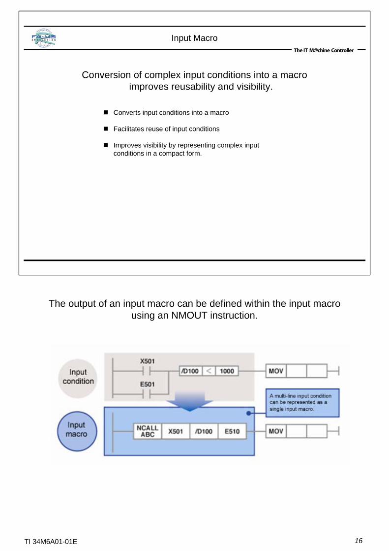
Conversion of complex input conditions into a macro improves reusability and visibility.
Converts input conditions into a macro
Facilitates reuse of input conditions
Improves visibility by representing complex inputconditions in a compact form.
The output of an input macro can be defined within the input macro using an NMOUT instruction.

17TI 34M6A01-01E
Indirect Specification
Improves parameter visibility and program reusability.
Improves program reusability by allowing pointer-like address modificationprovided in the C programming language.
A device can be passed as a parameter to a subroutine or block using indirect specification.
Sets address
Sets address
Calls subroutine
SET@ X201 @D001
SET@ B00001 @D004
CALL ABC
@D001
SubroutineABC
Moves data stored in B50001
X201
Adds to address
Indirect specification
ADD@ @D004 50000
MOV @D004
Indirect specification simplifies program code sharing.
18TI 34M6A01-01E
Downloading Comments
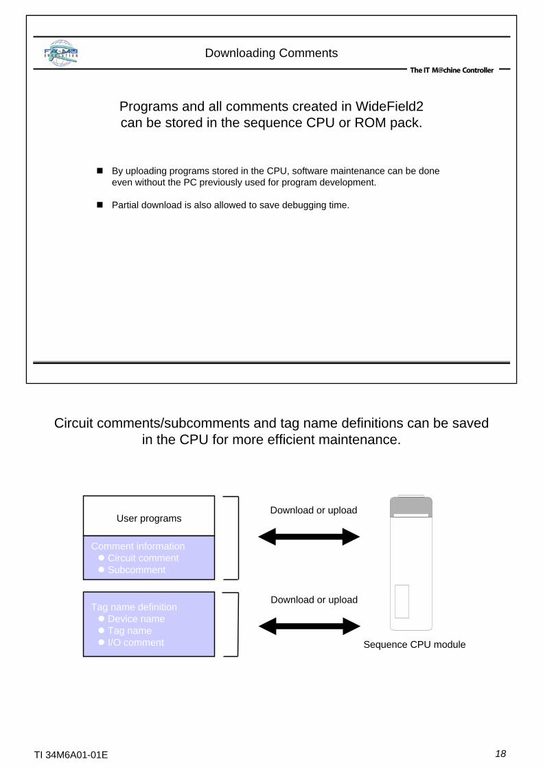
By uploading programs stored in the CPU, software maintenance can be done even without the PC previously used for program development.
Partial download is also allowed to save debugging time.
Programs and all comments created in WideField2 can be stored in the sequence CPU or ROM pack.
Tag name definitionDevice nameTag nameI/O comment
Comment informationCircuit commentSubcomment
User programs
Sequence CPU module
Download or upload
Download or upload
Circuit comments/subcomments and tag name definitions can be saved in the CPU for more efficient maintenance.
19TI 34M6A01-01E
Program Component
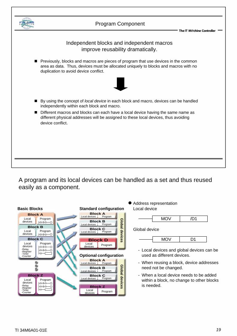
Previously, blocks and macros are pieces of program that use devices in the common area as data. Thus, devices must be allocated uniquely to blocks and macros with no duplication to avoid device conflict.
By using the concept of local device in each block and macro, devices can be handled independently within each block and macro.Different macros and blocks can each have a local device having the same name as different physical addresses will be assigned to these local devices, thus avoiding device conflict.
Independent blocks and independent macros improve reusability dramatically.
A program and its local devices can be handled as a set and thus reused easily as a component.
Address representationLocal device
Global device
- Local devices and global devices can be used as different devices.
- When reusing a block, device addresses need not be changed.
- When a local device needs to be added within a block, no change to other blocks is needed.
MOV /D1
MOV D1
Standard configuration
Optional configuration
Global devices
Basic BlocksBlock A
Localdevices
Program
Block BLocal
devicesProgram
Block CLocal
devices-Relay-Register-Timer-Counter
Program
Localdevices
-Relay-Register-Timer-Counter
ProgramBlock Z
Block DLocal
devices Program
Localdevices Program
Local devices
Local devices
Local devices
Program
Program
Program
Block A
Block B
Block C
Local devices
Local devices
Local devices
Program
Program
Program
Block A
Block B
Block C
Global devicesBlock Z
20TI 34M6A01-01E
�Supply of materials
� Preparatory heating
� Flacks coating
� Formalting
� Idling�
� �
� Supply of materials
� Preparatory heating
� Flacks coating
� Coating
� Fixing heating
� Cleaning
� Cooling
� Unloading� � �
� Diagnosis
� Power off
� Formalting
� Idling� � �
� Supply of materials
� Preparatory heating
� Flacks coating
� Coating
� Fixing heating
� Cleaning
� Cooling
� Unloading
� Diagnosis
� Power off
Index View
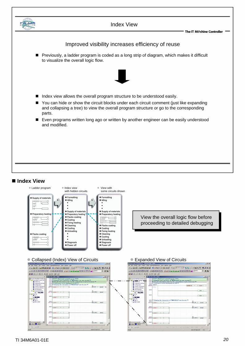
Previously, a ladder program is coded as a long strip of diagram, which makes it difficult to visualize the overall logic flow.
Index view allows the overall program structure to be understood easily.You can hide or show the circuit blocks under each circuit comment (just like expanding and collapsing a tree) to view the overall program structure or go to the corresponding parts.Even programs written long ago or written by another engineer can be easily understood and modified.
Improved visibility increases efficiency of reuse
Index View
Collapsed (Index) View of Circuits Expanded View of Circuits
View the overall logic flow before proceeding to detailed debugging
Ladder program Index view with hidden circuits
View with some circuits shown
21TI 34M6A01-01E
Collective Change of I/O Positions
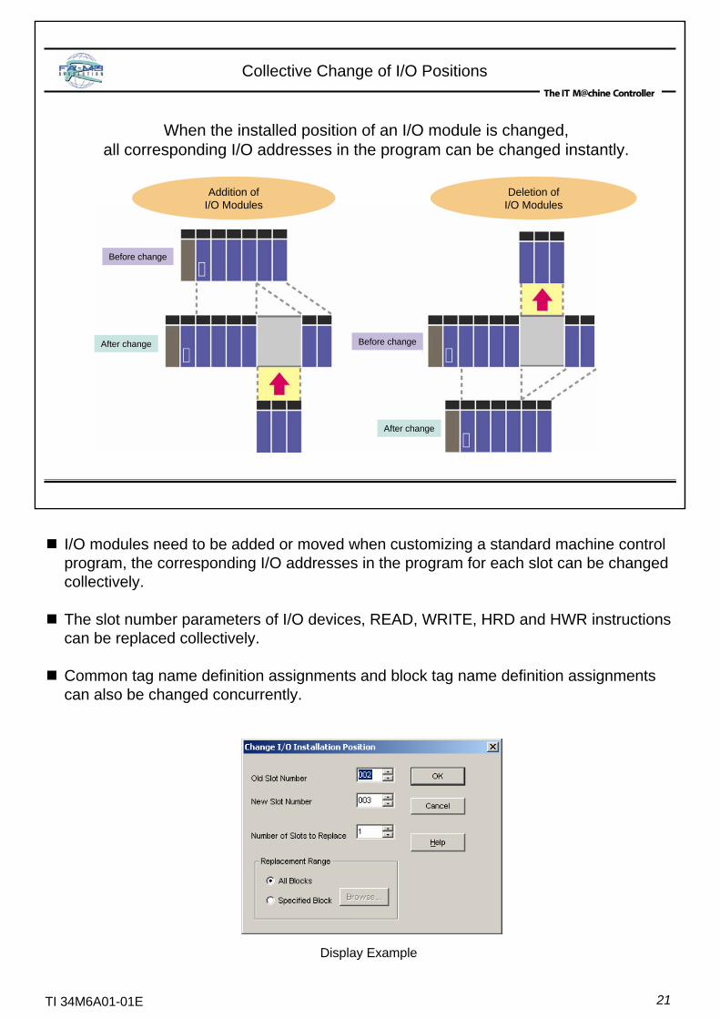
When the installed position of an I/O module is changed, all corresponding I/O addresses in the program can be changed instantly.
Addition of I/O Modules
Deletion of I/O Modules
Before change
After change Before change
After change
I/O modules need to be added or moved when customizing a standard machine control program, the corresponding I/O addresses in the program for each slot can be changed collectively.
The slot number parameters of I/O devices, READ, WRITE, HRD and HWR instructions can be replaced collectively.
Common tag name definition assignments and block tag name definition assignments can also be changed concurrently.
Display Example

22TI 34M6A01-01E
A meaningful name can be assigned to each device to improve maintainability.
Arbitrary tag names for individual devices can be used in programs before terminal assignment is decided. This separation of logical design and physical design (i.e., program design and terminal assignment) shortens engineering time significantly.
Wiring changes can be accomplished simply by changing tag definitions.
Use of tag names helps standardize circuits and facilitates reuse of programs.
Logical Design by Tag Name
Tag names can be defined easily (see the figure on the right); Moreover, tag names can be used in ladder diagrams even before they are defined.
In other words, programs can be developed using tag names even before terminal assignments are decided.
Tag names must be up to 8 characters long, beginning with 2 alphanumeric characters. Tag names are case insensitive.
Display Example
23TI 34M6A01-01E
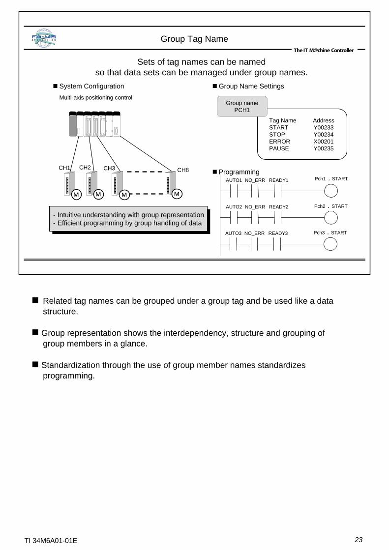
Sets of tag names can be named so that data sets can be managed under group names.
Group Tag Name
System ConfigurationMulti-axis positioning control
Group Name Settings
Tag Name AddressSTART Y00233STOP Y00234ERROR X00201PAUSE Y00235
Group namePCH1
Programming
- Intuitive understanding with group representation- Efficient programming by group handling of data
- Intuitive understanding with group representation- Efficient programming by group handling of data
Pch1 . STARTAUTO1 NO_ERR READY1
Pch2 . STARTAUTO2 NO_ERR READY2
Pch3 . STARTAUTO3 NO_ERR READY3
CH1 CH2 CH3 CH8
C
H
1
C
H
2
C
H
3
C
H
3
M M M M
Related tag names can be grouped under a group tag and be used like a data structure.
Group representation shows the interdependency, structure and grouping of group members in a glance.
Standardization through the use of group member names standardizes programming.
24TI 34M6A01-01E
Flexible Find Functionincreases programming and debugging efficiency
Standardized “Find” operationBoth finding within a block and finding within an entire project can be initiated from a Find toolbar located at the top of the screen. Using this function, you can search for the same device within a single block, as well as within an entire project.
Quick findSimply pressing the [Shift+F3] finds the next instance of the device name at the cursor position.
Finding hidden devicesInstructions such as BMOV which use multiple devices are displayed only with the first device on the screen even though subsequent devices are actually also used. WideField2 allows you to find even such hidden devices.
Finding using tag names or addressesIf tag names are used in programming, tag names are displayed in circuits.A tag name will be found even if a search request uses the address assigned to the tag name.
Major improvements to the “Find” function, which is used frequently in application programming and debugging.
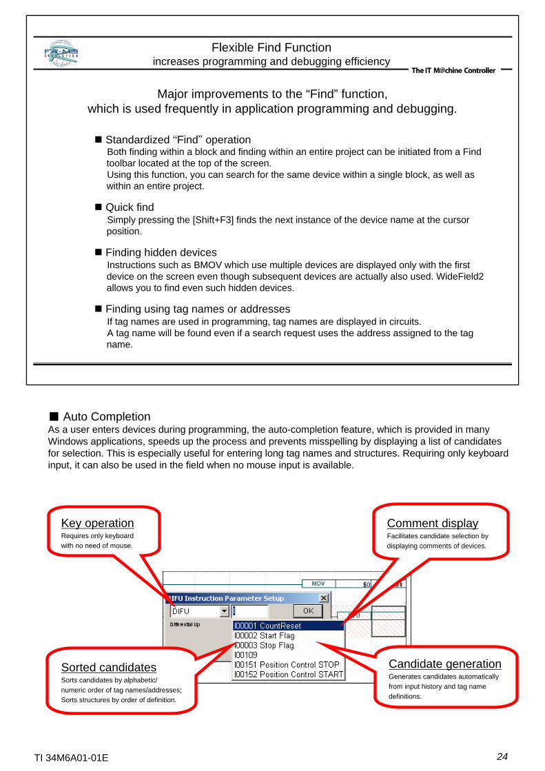
■ Auto CompletionAs a user enters devices during programming, the auto-completion feature, which is provided in many Windows applications, speeds up the process and prevents misspelling by displaying a list of candidates for selection. This is especially useful for entering long tag names and structures. Requiring only keyboard input, it can also be used in the field when no mouse input is available.
Comment displayFacilitates candidate selection by displaying comments of devices.
Sorted candidatesSorts candidates by alphabetic/numeric order of tag names/addresses; Sorts structures by order of definition.
Candidate generationGenerates candidates automatically from input history and tag name definitions.
Key operationRequires only keyboard with no need of mouse.
25TI 34M6A01-01E
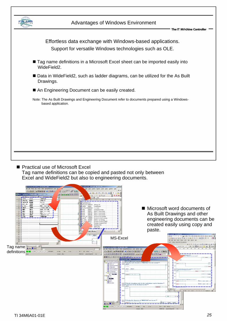
Tag name definitions in a Microsoft Excel sheet can be imported easily intoWideField2.
Data in WideField2, such as ladder diagrams, can be utilized for the As Built Drawings.
An Engineering Document can be easily created.
Note: The As Built Drawings and Engineering Document refer to documents prepared using a Windows-based application.
Advantages of Windows Environment
Effortless data exchange with Windows-based applications.Support for versatile Windows technologies such as OLE.
Practical use of Microsoft ExcelTag name definitions can be copied and pasted not only between Excel and WideField2 but also to engineering documents.
Microsoft word documents of As Built Drawings and other engineering documents can be created easily using copy and paste.
Tag namedefinitions
MS-Excel

26TI 34M6A01-01E
Ladder diagrams can be modified like editing a document with a word processor.Programming problems are minimized and operability maximized.
Flexible Operability
Program modification and monitoring can be done simultaneously by opening multiple windows.Both mouse and key operations are supported.Connection lines can be dawn and deleted by dragging.Shortcut menus displayed by right-clicking provide quick access to commands valid for that screen region or selection.A range of a ladder diagram can be copied and pasted between different programs.From a list of search results, a desired point can be retrieved.All instructions can be entered by typing their mnemonics, and automatically converted to the corresponding device on the screen.You can select a device type from the I/O configuration and monitor the statuses of the corresponding devices.
Display Example
Intuitive operations using visual icons.
Comments and circuits are differentiated by color.
File structure can be viewed during programming.
Allows constant monitoring of CPU operating status.
27TI 34M6A01-01E
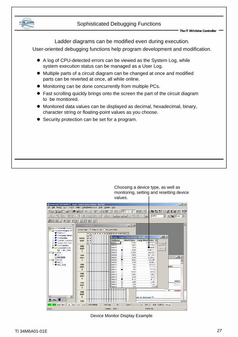
Ladder diagrams can be modified even during execution.User-oriented debugging functions help program development and modification.
Sophisticated Debugging Functions
A log of CPU-detected errors can be viewed as the System Log, while system execution status can be managed as a User Log.Multiple parts of a circuit diagram can be changed at once and modified parts can be reverted at once, all while online.Monitoring can be done concurrently from multiple PCs.Fast scrolling quickly brings onto the screen the part of the circuit diagram to be monitored.Monitored data values can be displayed as decimal, hexadecimal, binary, character string or floating-point values as you choose.Security protection can be set for a program.
Device Monitor Display Example
Choosing a device type, as well as monitoring, setting and resetting device values.
28TI 34M6A01-01E
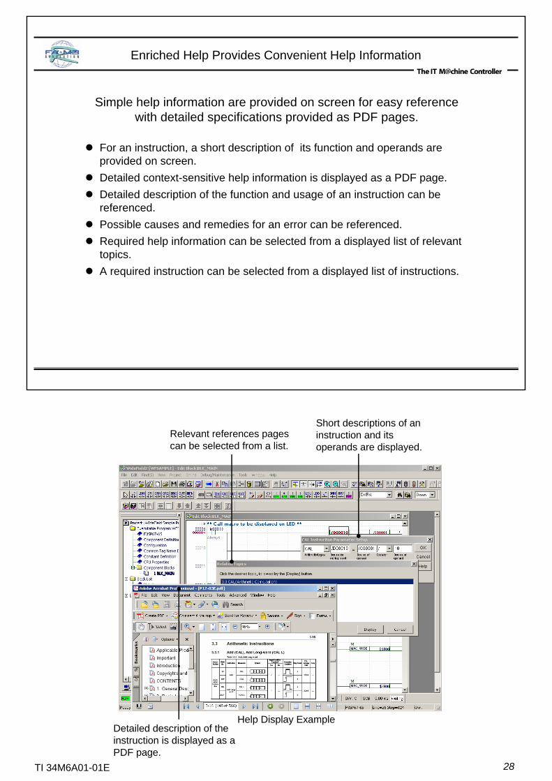
Simple help information are provided on screen for easy referencewith detailed specifications provided as PDF pages.
Enriched Help Provides Convenient Help Information
For an instruction, a short description of its function and operands are provided on screen.Detailed context-sensitive help information is displayed as a PDF page.Detailed description of the function and usage of an instruction can be referenced.Possible causes and remedies for an error can be referenced.Required help information can be selected from a displayed list of relevant topics.A required instruction can be selected from a displayed list of instructions.
Short descriptions of an instruction and its operands are displayed.
Relevant references pages can be selected from a list.
Detailed description of the instruction is displayed as a PDF page.
Help Display Example
29TI 34M6A01-01E
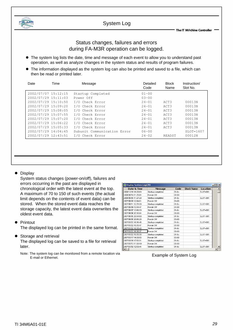
The system log lists the date, time and message of each event to allow you to understand past operation, as well as analyze changes in the system status and results of program failures.The information displayed as the system log can also be printed and saved to a file, which can then be read or printed later.
System Log
2002/07/07 15:12:15 Startup Completed 01-002002/07/29 15:11:03 Power Off 03-002002/07/29 15:10:50 I/O Check Error 24-01 ACT3 00013N2002/07/29 15:09:20 I/O Check Error 24-01 ACT3 00013N2002/07/29 15:08:05 I/O Check Error 24-01 ACT3 00013N2002/07/29 15:07:55 I/O Check Error 24-01 ACT3 00013N2002/07/29 15:07:20 I/O Check Error 24-01 ACT3 00013N2002/07/29 15:06:22 I/O Check Error 24-01 ACT3 00013N2002/07/29 15:05:33 I/O Check Error 24-01 ACT3 00013N2002/07/29 14:04:45 Subunit Communication Error 06-00 SLOT=16072002/07/29 12:43:51 I/O Check Error 24-02 READST 00012N
Status changes, failures and errors during FA-M3R operation can be logged.
Date Time Message Detailed Block Instruction/Code Name Slot No.
DisplaySystem status changes (power-on/off), failures anderrors occurring in the past are displayed inchronological order with the latest event at the top.A maximum of 70 to 150 of such events (the actuallimit depends on the contents of event data) can bestored. When the stored event data reaches thestorage capacity, the latest event data overwrites theoldest event data.
PrintoutThe displayed log can be printed in the same format.
Storage and retrievalThe displayed log can be saved to a file for retrievallater.Note: The system log can be monitored from a remote location via
E-mail or Ethernet. Example of System Log
30TI 34M6A01-01E
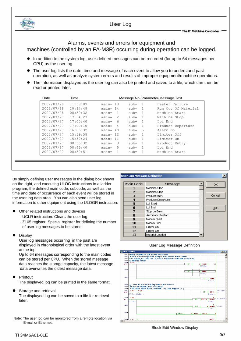
In addition to the system log, user-defined messages can be recorded (for up to 64 messages per CPU) as the user log.The user log lists the date, time and message of each event to allow you to understand past operation, as well as analyze system errors and results of improper equipment/machine operations.The information displayed as the user log can also be printed and saved to a file, which can then be read or printed later.
User Log
2002/07/28 11:59:09 main= 18 sub= 1 Heater Failure2002/07/28 10:34:48 main= 14 sub= 1 Run Out Of Material2002/07/28 08:30:32 main= 1 sub= 1 Machine Start2002/07/27 17:34:27 main= 2 sub= 1 Machine Stop2002/07/27 17:05:40 main= 6 sub= 1 Lot End2002/07/27 17:00:10 main= 4 sub= 1 Product Departure2002/07/27 16:05:32 main= 40 sub= 5 Alarm On2002/07/27 15:59:58 main= 12 sub= 1 Limiter Off2002/07/27 15:57:24 main= 11 sub= 1 Limiter On2002/07/27 08:55:32 main= 3 sub= 1 Product Entry2002/07/27 08:45:40 main= 5 sub= 1 Lot End2002/07/27 08:30:51 main= 1 sub= 1 Machine Start
Date Time Message No./Parameter/Message Text
Alarms, events and errors for equipment and machines (controlled by an FA-M3R) occurring during operation can be logged.
By simply defining user messages in the dialog box shown on the right, and executing ULOG instructions in a ladder program, the defined main code, subcode, as well as the time and date of occurrence of each event will be stored in the user log data area. You can also send user log information to other equipment using the ULOGR instruction.
Other related instructions and devices- UCLR instruction: Clears the user log.
- Z105 register: Special register for defining the numberof user log messages to be stored
DisplayUser log messages occurring in the past are displayed in chronological order with the latest eventat the top. Up to 64 messages corresponding to the main codescan be stored per CPU. When the stored messagedata reaches the storage capacity, the latest messagedata overwrites the oldest message data.
PrintoutThe displayed log can be printed in the same format.
Storage and retrievalThe displayed log can be saved to a file for retrievallater.
Note: The user log can be monitored from a remote location via E-mail or Ethernet.
Block Edit Window Display
User Log Message Definition
31TI 34M6A01-01E
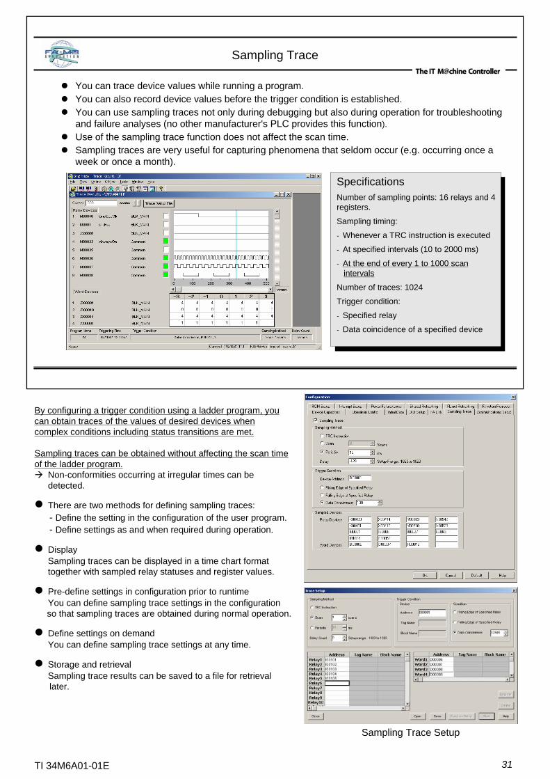
SpecificationsNumber of sampling points: 16 relays and 4registers.
Sampling timing:
- Whenever a TRC instruction is executed
- At specified intervals (10 to 2000 ms)
- At the end of every 1 to 1000 scanintervals
Number of traces: 1024
Trigger condition:
- Specified relay
- Data coincidence of a specified device
You can trace device values while running a program.You can also record device values before the trigger condition is established.You can use sampling traces not only during debugging but also during operation for troubleshooting and failure analyses (no other manufacturer's PLC provides this function).Use of the sampling trace function does not affect the scan time.Sampling traces are very useful for capturing phenomena that seldom occur (e.g. occurring once a week or once a month).
Sampling Trace
By configuring a trigger condition using a ladder program, you can obtain traces of the values of desired devices when complex conditions including status transitions are met.
Sampling traces can be obtained without affecting the scan time of the ladder program.
Non-conformities occurring at irregular times can bedetected.
There are two methods for defining sampling traces:- Define the setting in the configuration of the user program.- Define settings as and when required during operation.
DisplaySampling traces can be displayed in a time chart formattogether with sampled relay statuses and register values.
Pre-define settings in configuration prior to runtimeYou can define sampling trace settings in the configurationso that sampling traces are obtained during normal operation.
Define settings on demandYou can define sampling trace settings at any time.
Storage and retrievalSampling trace results can be saved to a file for retrievallater.
Sampling Trace Setup
32TI 34M6A01-01E
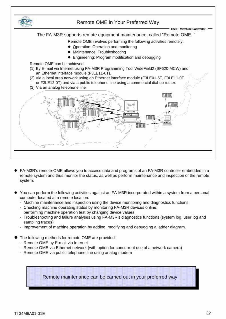
The FA-M3R supports remote equipment maintenance, called "Remote OME. "Remote OME involves performing the following activities remotely:
Operation: Operation and monitoringMaintenance: TroubleshootingEngineering: Program modification and debugging
Remote OME can be achieved:(1) By E-mail via Internet using FA-M3R Programming Tool WideField2 (SF620-MCW) and
an Ethernet interface module (F3LE11-0T).(2) Via a local area network using an Ethernet interface module (F3LE01-5T, F3LE11-0T
or F3LE12-0T) and via a public telephone line using a commercial dial-up router.(3) Via an analog telephone line
Remote OME in Your Preferred Way
Remote maintenance can be carried out in your preferred way. Remote maintenance can be carried out in your preferred way.
FA-M3R’s remote-OME allows you to access data and programs of an FA-M3R controller embedded in a remote system and thus monitor the status, as well as perform maintenance and inspection of the remote system.
You can perform the following activities against an FA-M3R incorporated within a system from a personal computer located at a remote location:- Machine maintenance and inspection using the device monitoring and diagnostics functions- Checking machine operating status by monitoring FA-M3R devices online;
performing machine operation test by changing device values- Troubleshooting and failure analyses using FA-M3R's diagnostics functions (system log, user log and
sampling traces)- Improvement of machine operation by adding, modifying and debugging a ladder diagram.
The following methods for remote OME are provided:- Remote OME by E-mail via Internet- Remote OME via Ethernet network (with option for concurrent use of a network camera)- Remote OME via public telephone line using analog modem
33TI 34M6A01-01E
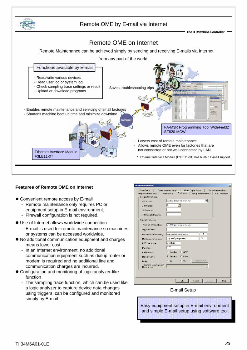
Remote OME by E-mail via Internet
Remote OME on InternetRemote Maintenance can be achieved simply by sending and receiving E-mails via Internet
from any part of the world.
- Enables remote maintenance and servicing of small factories- Shortens machine boot up time and minimize downtime
- Lowers cost of remote maintenance- Allows remote OME even for factories that are
not connected or not well-connected by LAN
- Saves troubleshooting trips
FA-M3R Programming Tool WideField2SF620-MCW
Ethernet Interface ModuleF3LE11-0T
- Read/write various devices- Read user log or system log- Check sampling trace settings or result- Upload or download programs
Functions available by E-mail
* Ethernet Interface Module (F3LE11-0T) has built-in E-mail support.
Features of Remote OME on Internet
Convenient remote access by E-mail- Remote maintenance only requires PC or
equipment setup in E-mail environment.- Firewall configuration is not required.
Use of Internet allows worldwide connection- E-mail is used for remote maintenance so machines
or systems can be accessed worldwide. No additional communication equipment and charges
means lower cost- In an Internet environment, no additional
communication equipment such as dialup router or modem is required and no additional line and communication charges are incurred.
Configuration and monitoring of logic analyzer-like function
- The sampling trace function, which can be used like a logic analyzer to capture device data changes using triggers, can be configured and monitored simply by E-mail.
E-mail Setup
Easy equipment setup in E-mail environment and simple E-mail setup using software tool.
34TI 34M6A01-01E
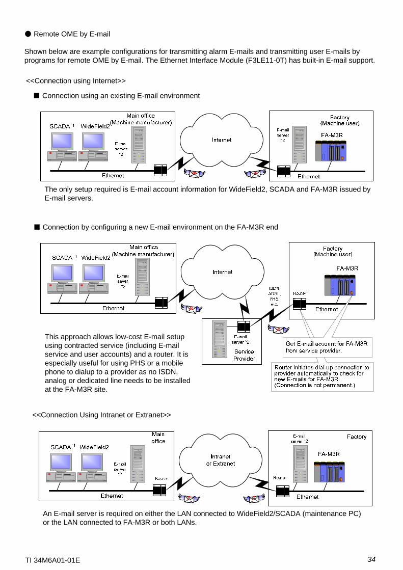
● Remote OME by E-mail
Shown below are example configurations for transmitting alarm E-mails and transmitting user E-mails by programs for remote OME by E-mail. The Ethernet Interface Module (F3LE11-0T) has built-in E-mail support.
<<Connection using Internet>>
<<Connection Using Intranet or Extranet>>
The only setup required is E-mail account information for WideField2, SCADA and FA-M3R issued by E-mail servers.
■ Connection using an existing E-mail environment
■ Connection by configuring a new E-mail environment on the FA-M3R end
This approach allows low-cost E-mail setup using contracted service (including E-mail service and user accounts) and a router. It is especially useful for using PHS or a mobile phone to dialup to a provider as no ISDN, analog or dedicated line needs to be installed at the FA-M3R site.
An E-mail server is required on either the LAN connected to WideField2/SCADA (maintenance PC) or the LAN connected to FA-M3R or both LANs.

35TI 34M6A01-01E
Analog line
WideField2SCADA*1
Mobile equipment Factory
Dialup router for analog line
Modem for analog line
E-mail server *2
WideField2SCADA*1
Mobile equipment
USB cable
Mobile phone
Ethernet Ethernet
Main office Factory
EthernetISDN
TAISDN router
E-mail server *2
WideField2SCADA *1
Ethernet
WideField2SCADA *1
Mobile equpiment
PHS card
<<Connection Using Public Line>>
Also allows dialup connection using PIAFS-enabled ISDN router and PIAFS-capable PHS.
This approach is useful in situations where dial-up connection to an E-mail server is allowed but not direct access to the FA-M3R.
*1: Remote OME via E-mail requires a separate E-mail-capable OPC server.*2: An SMTP/POP3 E-mail server is required for connection using WideField2 and F3LE11-0T Ethernet Interface Module.
* PIAFS: Standard specification for 32K/64K data communication
■ ISDN Connection
■ PHS Connection
■ Analog Connection
36TI 34M6A01-01E
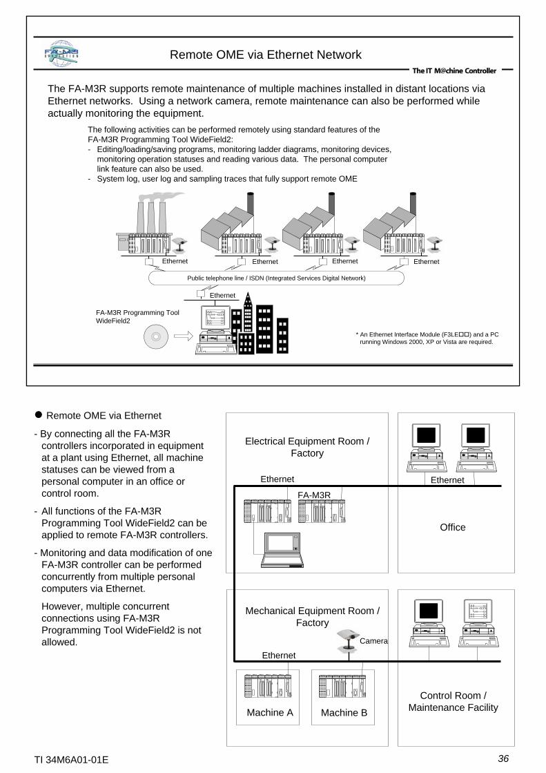
Remote OME via Ethernet
- By connecting all the FA-M3R controllers incorporated in equipment at a plant using Ethernet, all machinestatuses can be viewed from a personal computer in an office or control room.
- All functions of the FA-M3R Programming Tool WideField2 can be applied to remote FA-M3R controllers.
- Monitoring and data modification of one FA-M3R controller can be performed concurrently from multiple personal computers via Ethernet.
However, multiple concurrent connections using FA-M3R Programming Tool WideField2 is not allowed.
Ethernet
Ethernet
EthernetEthernet Ethernet
The FA-M3R supports remote maintenance of multiple machines installed in distant locations via Ethernet networks. Using a network camera, remote maintenance can also be performed while actually monitoring the equipment.
Remote OME via Ethernet Network
The following activities can be performed remotely using standard features of the FA-M3R Programming Tool WideField2:- Editing/loading/saving programs, monitoring ladder diagrams, monitoring devices,
monitoring operation statuses and reading various data. The personal computerlink feature can also be used.
- System log, user log and sampling traces that fully support remote OME
* An Ethernet Interface Module (F3LE ) and a PC running Windows 2000, XP or Vista are required.
Public telephone line / ISDN (Integrated Services Digital Network)
FA-M3R Programming ToolWideField2
Electrical Equipment Room / Factory
Office
Ethernet
FA-M3R
Ethernet
Ethernet
Machine BMachine A
Camera
Mechanical Equipment Room / Factory
Control Room /Maintenance Facility
37TI 34M6A01-01E
FA-M3R FA-M3R FA-M3R
Network camera
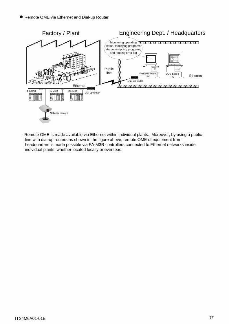
Remote OME via Ethernet and Dial-up Router
- Remote OME is made available via Ethernet within individual plants. Moreover, by using a publicline with dial-up routers as shown in the figure above, remote OME of equipment fromheadquarters is made possible via FA-M3R controllers connected to Ethernet networks insideindividual plants, whether located locally or overseas.
Factory / Plant Engineering Dept. / Headquarters
EthernetDial-up router
Monitoring operating status, modifying programs, starting/stopping programs,
and reading error log
Windows-basedPC
DOS-basedPC
Public line
Dial-up router
Ethernet
38TI 34M6A01-01E
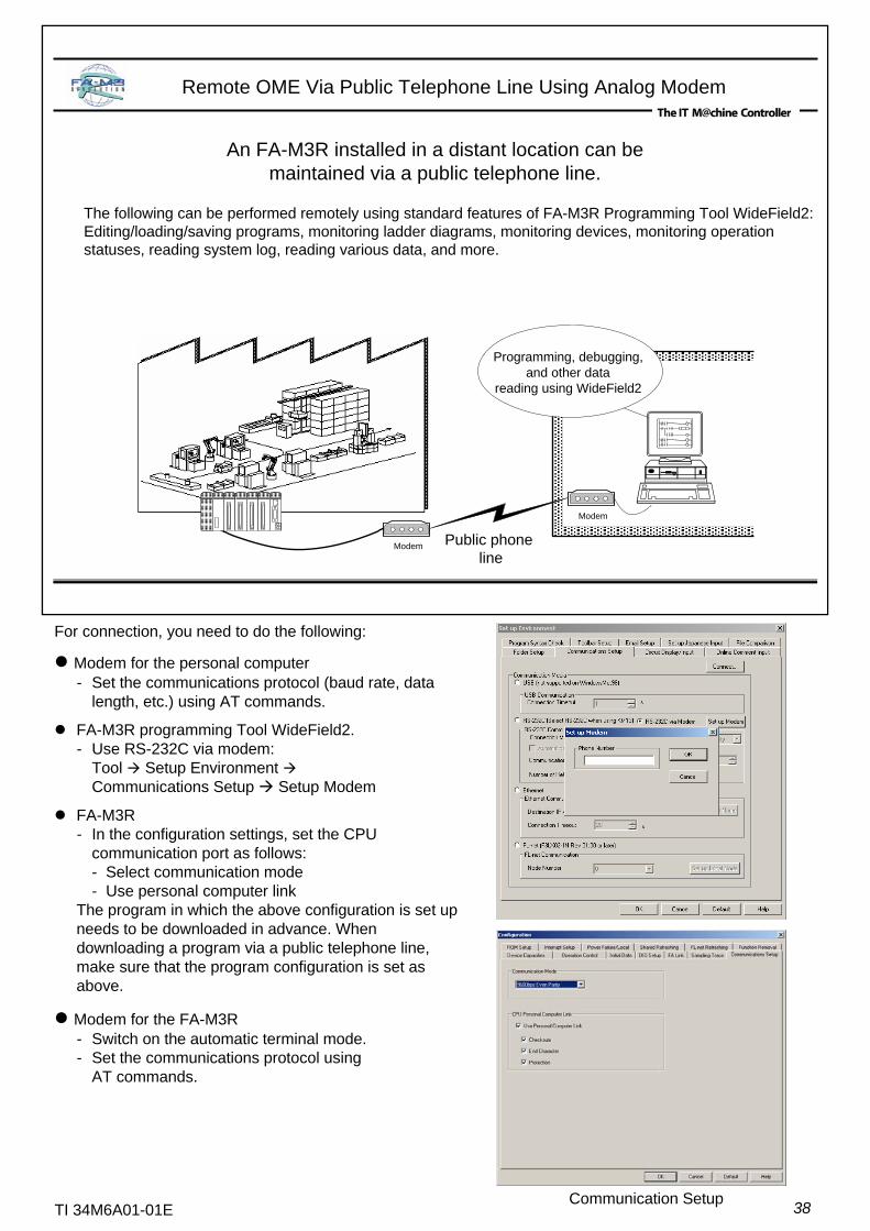
Remote OME Via Public Telephone Line Using Analog Modem
An FA-M3R installed in a distant location can be maintained via a public telephone line.
The following can be performed remotely using standard features of FA-M3R Programming Tool WideField2:Editing/loading/saving programs, monitoring ladder diagrams, monitoring devices, monitoring operation statuses, reading system log, reading various data, and more.
Public phone line
Modem
Modem
Programming, debugging,and other data
reading using WideField2
For connection, you need to do the following:
Modem for the personal computer- Set the communications protocol (baud rate, data
length, etc.) using AT commands.
FA-M3R programming Tool WideField2.- Use RS-232C via modem:
Tool Setup Environment Communications Setup Setup Modem
FA-M3R- In the configuration settings, set the CPU
communication port as follows:- Select communication mode- Use personal computer link
The program in which the above configuration is set up needs to be downloaded in advance. When downloading a program via a public telephone line, make sure that the program configuration is set as above.
Modem for the FA-M3R- Switch on the automatic terminal mode.- Set the communications protocol using
AT commands.
Communication Setup
39TI 34M6A01-01E
Advanced Function Module
(1)Analog Input Modules
(2)Analog Output Modules
Analog Input/Output Modules
High-speed Conversion, High Accuracy and Excellent Noise ImmunityModules can be combined with high-speed CPU modules to build high-speed analog I/O control systems.
―Supports filtering, scaling, channel skipping and noise-tolerant conversionOthers1ms50μs/250μs/1ms/16.6ms/20ms/100ms/166ms/200msConversion speed
0.2% of F.S.(23℃±2℃),0.5% of F.S. (0-55℃)
0.1%of F.S. (23℃±2℃),0.2% of F.S. (0-55℃)
Overall accuracy
Current signals only0-20mADC, 4-20 mADC
Current or voltage signals0-5VDC, 1-5VDC,
-10 to 10VDC, 0-10VDC0-20mADC, 4-20mADC
Voltage signals only0-5VDC, 1-5VDC,
-10 to 10VDC, 0-10VDC
Current signals only0-20mADC, 4-20 mADCInput signal range
12bit A/D16bit A/DResolution8No. of inputs
F3AD08-4VF3AD08-6RF3AD08-5RF3AD08-4RSpecifications
Item
Supports filtering, scaling, channel skipping and noise-tolerant conversionOthers1ms per inputConversion speed
0.1% of F.S. (23℃±2℃), 0.3% of F.S. (0-55℃)
0.2% of F.S. (23℃±2℃), 0.5% of F.S. (0-55℃)
Overall accuracy
0-5 VDC , 1-5 VDC, -10 to 10 VDCInput signal range16-bit A/D12-bit A/DResolution
484No. of inputsF3AD04-0RF3AD08-1VF3AD04-0V
SpecificationsItem
Hold outputs or outputs specified valueHold outputsOthers (output on CPU failure)
4ms2msConversion speed0.2% of F.S. (23℃±2℃), 0.5% of F.S. (0-55℃)Overall accuracy
-10 to 10VDC-10 to 10VDC, 4-20mADCOutput signal range
12bit A/DResolution842No. of outputs
F3DA08-5NF3DA04-1NF3DA02-0NSpecifications
Item
RDY
ALM
DA02-0N DAC
V+
V-OUT1
I+
I-
V+
V-OUT2
I+
I-
+
-
RDY
ALM
DA04-1N DAC
V+
-
V+
-
OUT1
V+
-
V+
-
OUT2
V+
-
V+
-
OUT3
V+
-
V+
-
OUT4
F3DA04-1NF3DA02-0N
RDY
ALM
AD08-1V ADC
IN1+
-
IN2+
-
IN3+
-
IN4+
-
IN8+
-
IN7+
-
IN6+
-
IN5+
-
SHIELD
AG
F3AD08-□VF3AD08-□R
RDY
ALM
AD04-0V ADC
+
-
IN1
+
-
IN2
+
-
IN3
+
-
IN4
SHIELD
SHIELD
F3AD04-0VF3AD04-0R
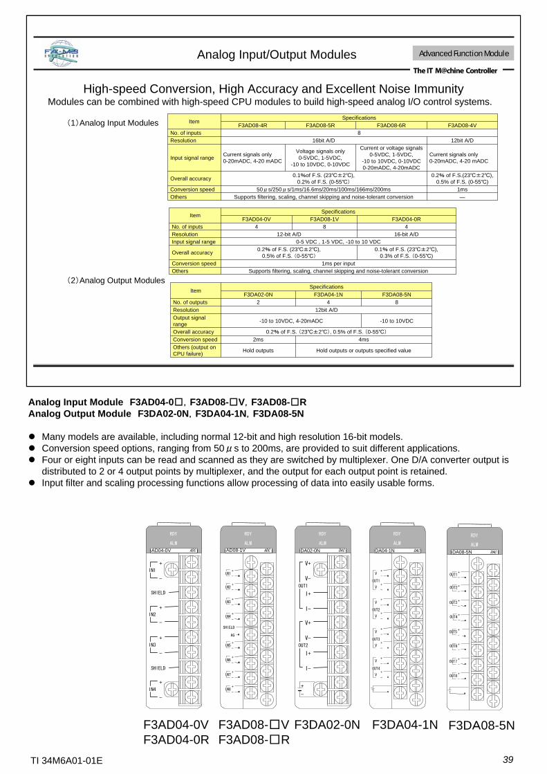
Analog Input Module F3AD04-0□,F3AD08-□V,F3AD08-□RAnalog Output Module F3DA02-0N,F3DA04-1N,F3DA08-5N
Many models are available, including normal 12-bit and high resolution 16-bit models.Conversion speed options, ranging from 50μs to 200ms, are provided to suit different applications.Four or eight inputs can be read and scanned as they are switched by multiplexer. One D/A converter output is distributed to 2 or 4 output points by multiplexer, and the output for each output point is retained.Input filter and scaling processing functions allow processing of data into easily usable forms.
RDY
ALM
DA08-5N DAC
OUT1+
-
OUT2+
-
OUT3+
-
OUT4+
-
OUT8+
-
OUT7+
-
OUT6+
-
OUT5+
-
F3DA08-5N
40TI 34M6A01-01E
Four Built-in A/D Converters
Capturing fast changing analog data at sampling period shorter than PLC cycle time(Concurrent data acquisition for 4 channels)
* 1 Configurable independently for each channel by software.* 2 Configurable on module basis. Valid data values depend on the number of channels used and whether filtering is used.
High-speed Data Acquisition Module Advanced function module
Activation by periodic timer or by external pacer inputA/D conversion
YesFilter
YesScaling
24 K wordInput buffer
50 μs min. when channels 1 to 4 are used.500 μs min. when channels 1 to 8 are used.Sampling period*2
23±2ºC: ±0.2% of F. S. 0-55ºC: ±0.5% of F. S.Overall accuracy
1.4 mV (for 0-5 V DC); 5.7 mV (for -10 to 10 V DC range)Resolution (12 bit ADC)
2M ΩInput resistance
Isolated by photocouplers between input terminals and internal circuitryNo isolation between input terminalsIsolation method
0 to 5 VDC (-0.25 to 5.25 VDC)-10 to 10 VDC (-11.0 to 11.0 VDC)Input signal range*1
8 differential inputsNumber of inputs
SpecificationsItem
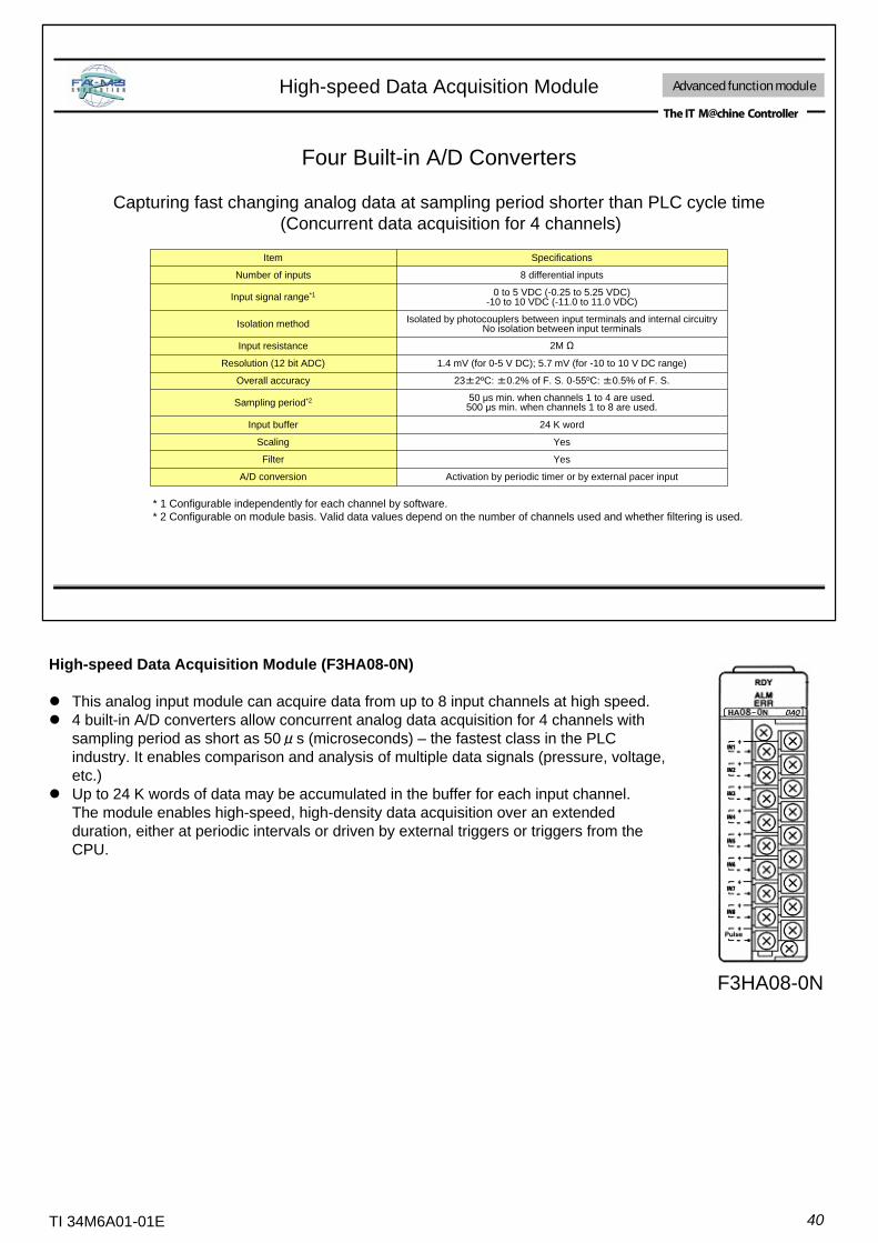
High-speed Data Acquisition Module (F3HA08-0N)
This analog input module can acquire data from up to 8 input channels at high speed. 4 built-in A/D converters allow concurrent analog data acquisition for 4 channels with sampling period as short as 50μs (microseconds) – the fastest class in the PLC industry. It enables comparison and analysis of multiple data signals (pressure, voltage, etc.)Up to 24 K words of data may be accumulated in the buffer for each input channel.The module enables high-speed, high-density data acquisition over an extended duration, either at periodic intervals or driven by external triggers or triggers from the CPU.
F3HA08-0N
41TI 34M6A01-01E
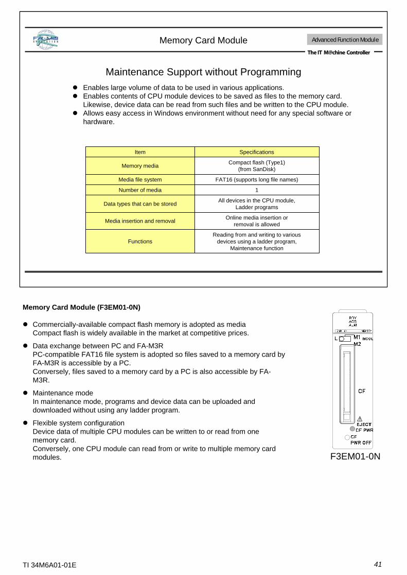
Maintenance Support without Programming
Reading from and writing to variousdevices using a ladder program,
Maintenance functionFunctions
Online media insertion orremoval is allowedMedia insertion and removal
All devices in the CPU module,Ladder programsData types that can be stored
1Number of media
FAT16 (supports long file names)Media file system
Compact flash (Type1)(from SanDisk)Memory media
SpecificationsItem
Memory Card Module
Enables large volume of data to be used in various applications.Enables contents of CPU module devices to be saved as files to the memory card. Likewise, device data can be read from such files and be written to the CPU module.Allows easy access in Windows environment without need for any special software or hardware.
Advanced Function Module
F3EM01-0N
Memory Card Module (F3EM01-0N)
Commercially-available compact flash memory is adopted as mediaCompact flash is widely available in the market at competitive prices.
Data exchange between PC and FA-M3RPC-compatible FAT16 file system is adopted so files saved to a memory card by FA-M3R is accessible by a PC.Conversely, files saved to a memory card by a PC is also accessible by FA-M3R.
Maintenance modeIn maintenance mode, programs and device data can be uploaded and downloaded without using any ladder program.
Flexible system configurationDevice data of multiple CPU modules can be written to or read from one memory card.Conversely, one CPU module can read from or write to multiple memory card modules.

42TI 34M6A01-01E
Four temperature control loops implemented by one compact FA-M3R module
Temperature Control/PID Modules Advanced Function Module
Same as input sampling cycleControl cycle
ON/OFF, PID, heating/cooling, settingoutput, dynamic auto-tuning, and "Super"Control functionControl
section
YesNoContinuous PID(4-20 mA output)
Yes (ON/OFF control, forward/reverse)Time proportioning PID(Open collector output)Output
type
YesBurnout detection function
250Ω max. for thermocouple and DC mV,100Ω max. for RTD (with same wire resistance),
and 2 kΩ max. for DC VAllowable signal impedance
1MΩ or moreInput impedance
100 ms for 2 channels or 200 ms for 4 channelsInput sampling cycle
Universal input (individual inputs configurable separately bysoftware or collectively by hardware): 15 thermocouples,
9 RTDs, 2 DC mV ranges, and 4 DC V rangesInput type
Between input terminals and internal circuit:Isolation by photocouplers and transformers
Between input terminals: Independent circuits for different channelsIsolation method
4 loopsNo. of loops
F3CU04-1SF3CU04-0S
SpecificationItem
F3CU04-0S F3CU04-1S
Temperature Control/PID Modules (F3CU04-0S, F3CU04-1S)
High-speed, High-Accuracy, High-ResolutionInput sampling cycle is 100 ms for 2 loops or 200 ms for 4 loops.Input conversion accuracy is ±0.1% of F.S.Input resolution is 0.1ºC (5-digit display).
Universal InputThermocouple, RTD, DC mV and DC V
Versatile Control ModesSupports single-loop, cascade, two-input changeover,heating/cooling output and continuous output controlwith output overshooting suppression function
Simple Control using Dynamic Auto-tuningSimply setting the input type, output type and control set point is sufficient to start operation.
ToolBox for Temperature Control and Monitoring ModulesCan be used to set up operation parameters easily
43TI 34M6A01-01E
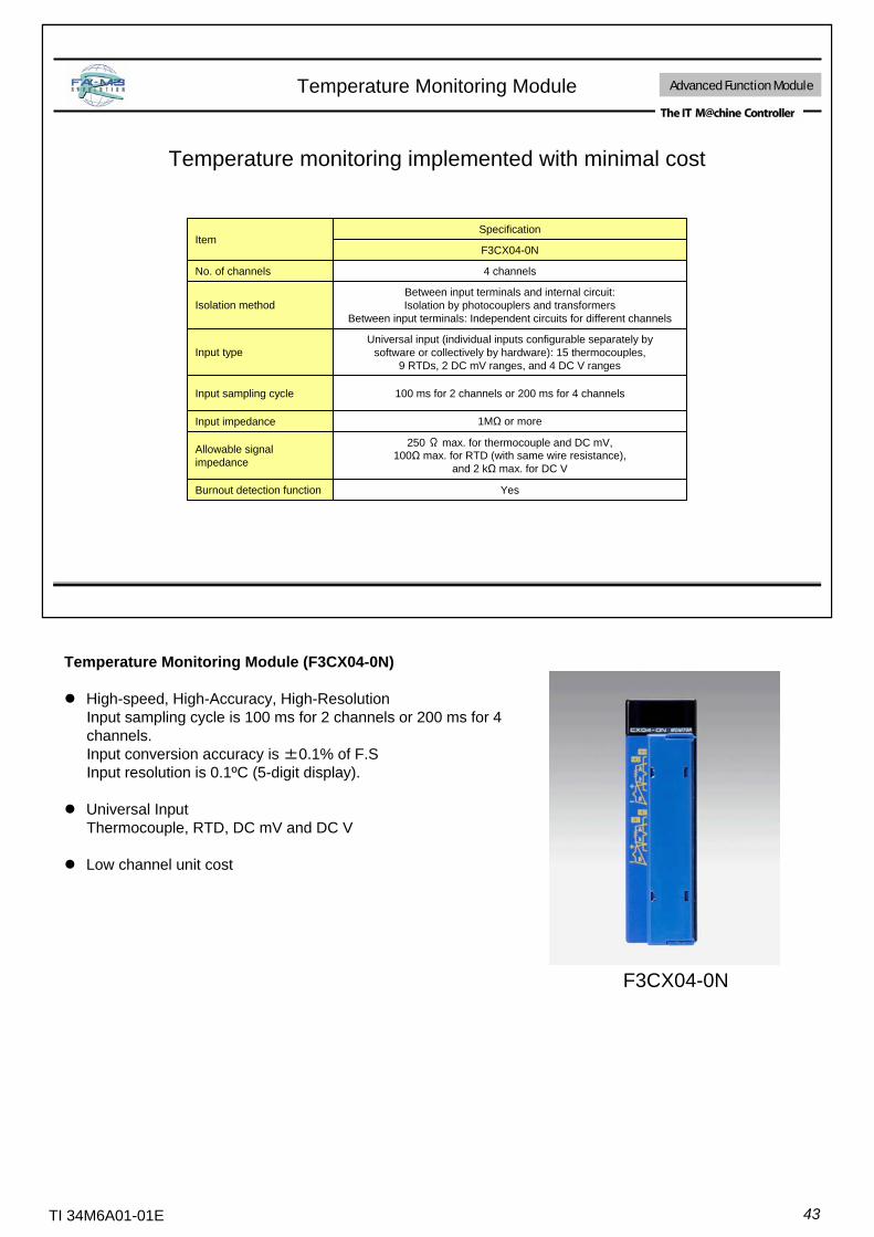
Temperature Monitoring Module Advanced Function Module
Temperature monitoring implemented with minimal cost
YesBurnout detection function
250 Ω max. for thermocouple and DC mV,100Ω max. for RTD (with same wire resistance),
and 2 kΩ max. for DC V
Allowable signal impedance
1MΩ or moreInput impedance
100 ms for 2 channels or 200 ms for 4 channelsInput sampling cycle
Universal input (individual inputs configurable separately bysoftware or collectively by hardware): 15 thermocouples,
9 RTDs, 2 DC mV ranges, and 4 DC V rangesInput type
Between input terminals and internal circuit:Isolation by photocouplers and transformers
Between input terminals: Independent circuits for different channelsIsolation method
4 channelsNo. of channels
F3CX04-0N
SpecificationItem
Temperature Monitoring Module (F3CX04-0N)
High-speed, High-Accuracy, High-ResolutionInput sampling cycle is 100 ms for 2 channels or 200 ms for 4 channels.Input conversion accuracy is ±0.1% of F.SInput resolution is 0.1ºC (5-digit display).
Universal InputThermocouple, RTD, DC mV and DC V
Low channel unit cost
F3CX04-0N

44TI 34M6A01-01E
Positioning Modules for Controlling Every Type of Motor
Built-in MECHATROLINK-II network interface for open, high-speed motion control- Controls up to 15 axes per module- Network connection enables lower cost and reduced wiring- High baud rate of 10Mbps supports short cycle time of 1 ms per set of 8 axes
F3NC96
Applicable MotorFeaturesModule
Speed control in combination with an inverterF3DA□□
Semi closed-loop controlGood controllability- Fast response (6 ms startup time) - En-route action, control mode switching by an external trigger signal - Biaxial arc interpolation; trapezoidal acceleration/deceleration- Position control, speed control, switchover between position-control and speed-control
F3NC51F3NC52
Open-loop controlFast, accurate positioning control- Output pulse rate of 5 Mpps for servomotor control or 1 Mpps for stepping motor controlRich positioning control functions- position control (PTP, CP and indexing),- speed control (switchover between speed-control and position-control)- interpolation modes (linear, circular, and helical interpolation)- operation modes (pattern operation using preset actions, direct operation by a ladder program)Built-in pulse counters and general purpose I/O contacts
F3NC32F3NC34
Open-loop controlControls up to 8 axes per module (up to 288 axes per system)- Fast response (0.09 ms startup time) • multi-axial linear interpolated positioning - Trapezoidal and S-shaped acceleration/deceleration
F3YP14F3YP18
Applicable MotorFeaturesModule
stepping motor
Induction motor
MECHATROLINK-ⅡcompatiblesN
etw
ork
enab
led
Servomotor
DD motor
Open-loop control (F3NC32-0N, F3NC34-0N, F3YP14-0N, F3YP18-0N)Based on reference data sent from a CPU module, the positioning module computes the positioning reference values and outputs them as pulse trains.
Semi-closed-loop control (F3NC51-0N and F3NC52-0N)Based on reference data sent from a CPU module, the positioning module performs position servo computation based on position feedback signal input from the external position sensor, and outputs speed reference values as an analog voltage signal.
Drive Current
ServomotorAnalogVoltage
Servo Driver
SpeedServo
Computation
CPU Module
PositioningServo
Computation
Positioning Module
Positioning Data Speed Data
FA-M3R
Speed Feedback
En-coder
Position Feedback
Encoder Output
Speed and Position Feedback
Drive Current
SpeedServo
Computation
Servo Driver
Positioning Module
CPU Module
Pulse Train Positioning Data
Speed Data
FA-M3R
Servomotor
PositioningServo
Computation En-coder
Encoder Output

45TI 34M6A01-01E
Example Application of Multiaxial Interpolation
Driver
Positioning Modules with Analog Voltage Output (F3NC51-0N and F3NC52-0N)
For motor control on either 1 or 2 axes per module. Outputs speed reference values as analog voltages to servomotors and servo drivers based on feedback signal from an external position sensor (encoder).High speed response of 6 ms max. from activation to pulse outputSuitable for various encoders:- Incremental encoders, including:
General-purpose two-phase rotary encoders- Absolute encoders, including:
Yaskawa Electric serial absolute encoderSanyo Denki serial absolute encoders and their compatibles
Motor control at a maximum speed of 2 Mpps in quad-speed mode- Can control a motor axis of 8000 pulses/rotation at 12000 rpm
(equivalent to 1.6 Mpps).A variety of available functions include:- Switching between speed control and position control, target position
changes, linear interpolation, arc interpolation and en-route movement
Trapezoidal, two-line segment and three-step S-shaped drives are available in both acceleration and deceleration modes.- No mechanical shock to transported goods- No mechanical stress to machines
Positioning Modules with Pulse Output (F3NC32-0N, F3NC34-0N)
For motor control on either 2 or 4 axes per module. High speed position reference pulse output at 5 Mpps max. for servo motor control and 1 Mppsmax. for stepping motor control.
High speed response of 0.15 ms per axis from activation to pulse output
Position control (PTP control, CP control and indexing control),
Speed control (switchover between speed-control and position-control)
Available interpolation modes include linear interpolation, arc interpolation and helical interpolation.
Supports pattern operation using preset actions and direct operation using a ladder program to specify target position and speed for each positioning action.
A 5-Mpps pulse counter (supporting absolute encoders) is provided for each axis.
6 general inputs and 3 general outputs are provided for each control axis. F3NC34-0NF3NC32-0N
F3NC51-0N F3NC52-0N
NC51-0N POSIT
RDY
ERR1
NC52-0N POSIT
RDYERR1ERR2
NC32-0N POSIT
RDY
ERR
NC34-0N POSIT
RDY
ERR
FA-M3R
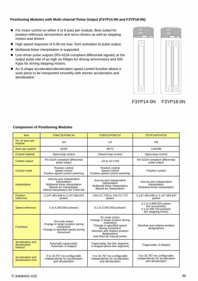
46TI 34M6A01-01E
For motor control on either 4 or 8 axes per module. Best suited for position-reference servomotors and servo drivers as well as stepping motors and drivers.High speed response of 0.09 ms max. from activation to pulse output.Multiaxial linear interpolation is supported.Line-driver pulse outputs (RS-422A-compliant differential signals) at the output pulse rate of as high as 4Mpps for driving servomotors and 500 Kpps for driving stepping motors.An S-shape acceleration/deceleration speed control function allows a work piece to be transported smoothly with shorter acceleration and deceleration.
YP14-0N POSIT
RDY
ERR
F3YP14-0N F3YP18-0N
YP18-0N POSIT
RDY
ERR
0 to 32,767 ms configurable independently for acceleration
and deceleration
0 to 32,767 ms configurable independently for acceleration
and deceleration
0 to 32,767 ms configurable independently for acceleration
and decelerationAcceleration and deceleration time
Trapezoidal, S-shapedTrapezoidal, two-line segment,S-shaped (three-line segment)
Automatic trapezoidal, Automatic S-shaped
Acceleration and deceleration method
Absolute and relative position designations
En-route actionChange in target position during
movementChange in specified speed
during movementAbsolute and relative position
designationsAxis feed by manual pulser
En-route actionChange in target position during
movementChange in specified speed during
movement
Functions
0.1 to 3,998,000 pulses (for servomotor)
0.1 to 449,750 pulses/s (for stepping motor)
0.1 to 2,000,000 pulses/s1 to 5,000,000 pulses/sSpeed reference
-2,147,483,648 to 2,147,483,647 pulses
-134,217,728 to 134,217,727 pulses
-2,147,483,648 to 2,147,483,647 pulses
Position reference
Axis-by-axis independent interpolation
Multiaxial linear interpolation
Axis-by-axis independent interpolation
Multiaxial linear interpolationBiaxial arc interpolation
Axis-by-axis independent interpolation
Multiaxial linear interpolationBiaxial arc interpolation
Helical interpolation (for F3NC34)
Interpolation
Position controlPosition controlSpeed control
Position-speed control switching
Position controlSpeed control
Position-speed control switchingControl mode
RS-422A-compliant differential pulse output-10 to 10 V DCRS-422A-compliant differential
pulse outputControl output
Open-loop controlClosed-loop controlOpen-loop controlControl method
144/28836/7232/64Axes per system
4/81/22/4No. of axes per module
F3YP14/F3YP18F3NC51/F3NC52F3NC32/F3NC34Item
Comparison of Positioning Modules
Positioning Modules with Multi-channel Pulse Output (F3YP14-0N and F3YP18-0N)
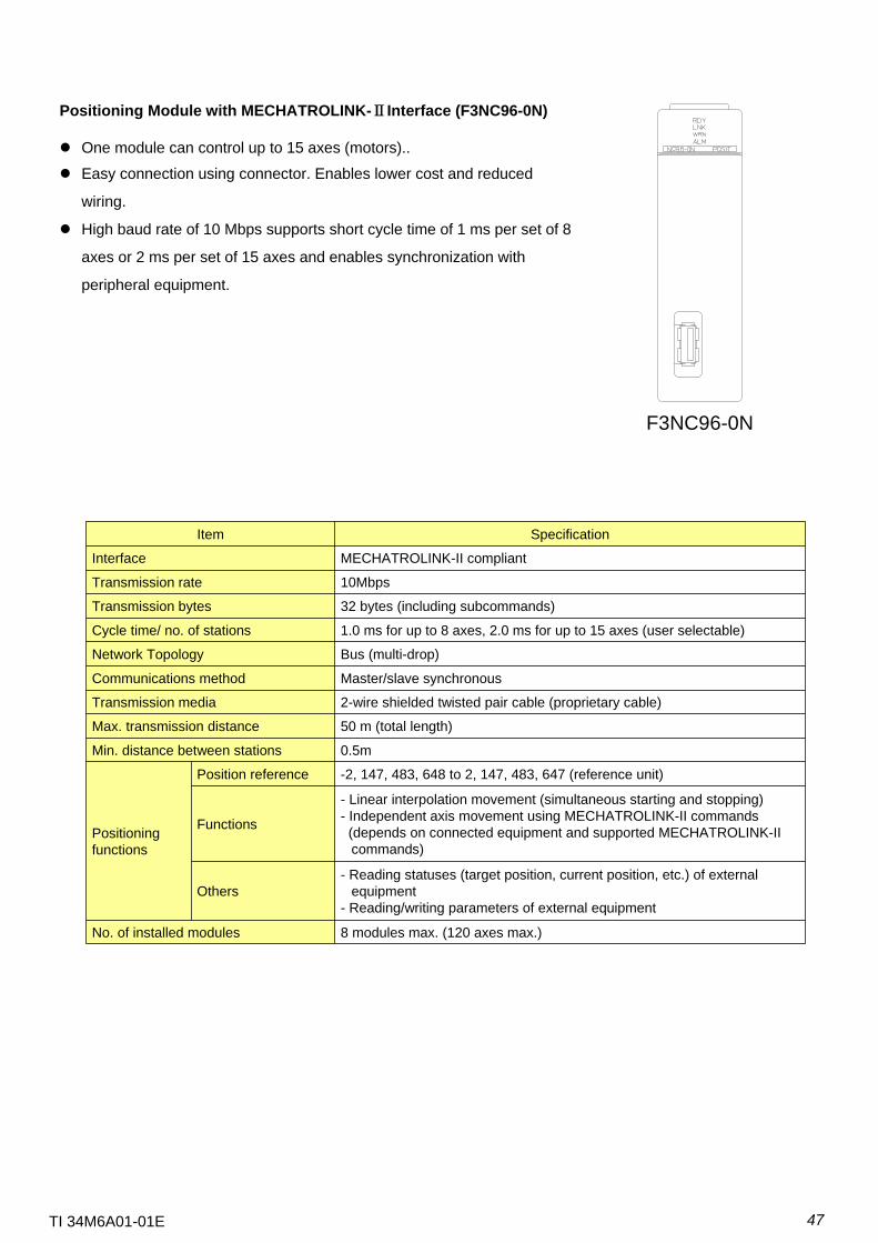
47TI 34M6A01-01E
Positioning Module with MECHATROLINK-ⅡInterface (F3NC96-0N)
One module can control up to 15 axes (motors)..
Easy connection using connector. Enables lower cost and reduced
wiring.
High baud rate of 10 Mbps supports short cycle time of 1 ms per set of 8
axes or 2 ms per set of 15 axes and enables synchronization with
peripheral equipment.
F3NC96-0N
8 modules max. (120 axes max.)No. of installed modules
- Reading statuses (target position, current position, etc.) of external equipment
- Reading/writing parameters of external equipmentOthers
- Linear interpolation movement (simultaneous starting and stopping)- Independent axis movement using MECHATROLINK-II commands
(depends on connected equipment and supported MECHATROLINK-II commands)
Functions
-2, 147, 483, 648 to 2, 147, 483, 647 (reference unit)Position reference
Positioningfunctions
0.5mMin. distance between stations
50 m (total length)Max. transmission distance
2-wire shielded twisted pair cable (proprietary cable)Transmission media
Master/slave synchronousCommunications method
Bus (multi-drop)Network Topology
1.0 ms for up to 8 axes, 2.0 ms for up to 15 axes (user selectable)Cycle time/ no. of stations
32 bytes (including subcommands)Transmission bytes
10MbpsTransmission rate
MECHATROLINK-II compliantInterface
SpecificationItem
48TI 34M6A01-01E
ToolBox Software for Advanced Function Modules
Software tool lineup for tapping performance of advanced function modules with ease
ToolBox for Temperature Control and Monitoring Modules (for F3CU04, F3CX04)
ToolBox for Positioning Modules (for F3NC32, F3NC34)
Supports concurrent use with FA-M3R Programming Tool WideField2
Supports network connection (via Internet) using Ethernet Interface Module
(F3LE□□)
FL-net connection via FL-net Interface Module (F3LX02) is also supported.
Can be executed from common ToolBox environment (by selecting the required
advanced function module from the ToolBox icon)
Future support for other modules expected
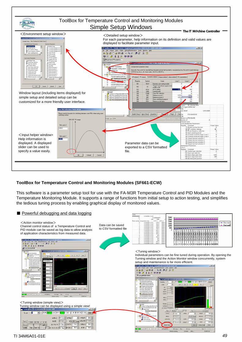
49TI 34M6A01-01E
ToolBox for Temperature Control and Monitoring ModulesSimple Setup Windows
Window layout (including items displayed) for simple setup and detailed setup can be customized for a more friendly user interface.
<Detailed setup window>For each parameter, help information on its definition and valid values are displayed to facilitate parameter input.
<Environment setup window>
<Input helper window>Help information is displayed. A displayed slider can be used to specify a value easily.
Parameter data can be exported to a CSV formatted file.
ToolBox for Temperature Control and Monitoring Modules (SF661-ECW)
This software is a parameter setup tool for use with the FA-M3R Temperature Control and PID Modules and the Temperature Monitoring Module. It supports a range of functions from initial setup to action testing, and simplifies the tedious tuning process by enabling graphical display of monitored values.
■ Powerful debugging and data logging
<Action monitor window>Channel control status of a Temperature Control and PID module can be saved as log data to allow analysis of application characteristics from measured data.
<Tuning window>Individual parameters can be fine tuned during operation. By opening the Turning window and the Action Monitor window concurrently, system setup and maintenance is far more efficient.
<Tuning window (simple view)>Tuning window can be displayed using a simple view!
Data can be saved to CSV formatted file
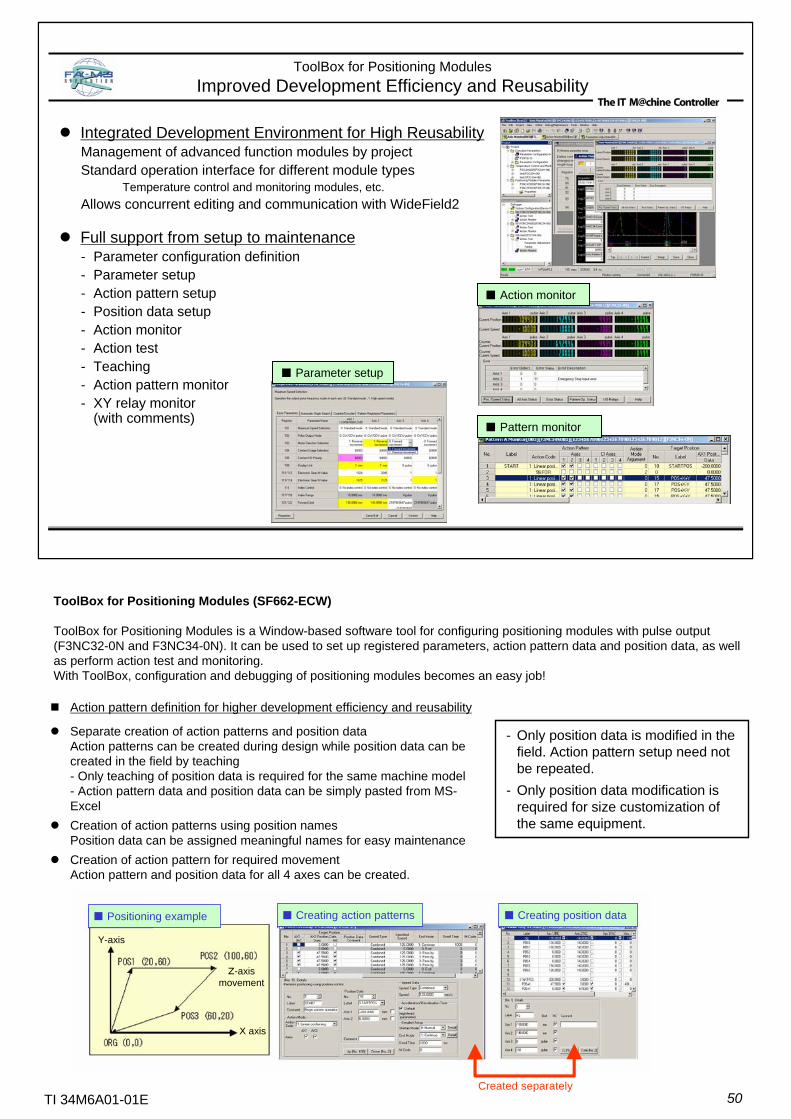
50TI 34M6A01-01E
■ Positioning example ■ Creating position data■ Creating action patterns
Created separately
ToolBox for Positioning Modules (SF662-ECW)
ToolBox for Positioning Modules is a Window-based software tool for configuring positioning modules with pulse output (F3NC32-0N and F3NC34-0N). It can be used to set up registered parameters, action pattern data and position data, as well as perform action test and monitoring.With ToolBox, configuration and debugging of positioning modules becomes an easy job!
Integrated Development Environment for High ReusabilityManagement of advanced function modules by projectStandard operation interface for different module types
Temperature control and monitoring modules, etc.Allows concurrent editing and communication with WideField2
Full support from setup to maintenance- Parameter configuration definition- Parameter setup- Action pattern setup- Position data setup- Action monitor- Action test- Teaching- Action pattern monitor- XY relay monitor
(with comments)
ToolBox for Positioning ModulesImproved Development Efficiency and Reusability
■ Parameter setup
■ Action monitor
■ Pattern monitor
- Only position data is modified in the field. Action pattern setup need not be repeated.
- Only position data modification is required for size customization of the same equipment.
Z-axis movement
Y-axis
X axis
Action pattern definition for higher development efficiency and reusability
Separate creation of action patterns and position dataAction patterns can be created during design while position data can be created in the field by teaching- Only teaching of position data is required for the same machine model- Action pattern data and position data can be simply pasted from MS-ExcelCreation of action patterns using position namesPosition data can be assigned meaningful names for easy maintenanceCreation of action pattern for required movementAction pattern and position data for all 4 axes can be created.
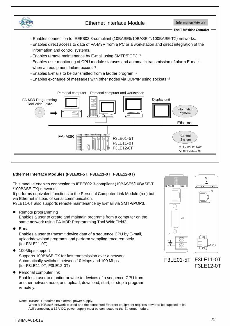
51TI 34M6A01-01E
Ethernet Interface Module
FA-M3R Programming Tool WideField2
Personal computer and workstation
F3LE01‐5TF3LE11‐0TF3LE12-0T
FA‐M3R
Ethernet
Information System
Personal computer
Display unit
- Enables connection to IEEE802.3-compliant (10BASE5/10BASE-T/100BASE-TX) networks.- Enables direct access to data of FA-M3R from a PC or a workstation and direct integration of the information and control systems.
- Enables remote maintenance by E-mail using SMTP/POP3 *1
- Enables user monitoring of CPU module statuses and automatic transmission of alarm E-mails when an equipment failure occurs *1
- Enables E-mails to be transmitted from a ladder program *1
- Enables exchange of messages with other nodes via UDP/IP using sockets *2
*1: for F3LE11-0T*2: for F3LE12-0T
Information Network
Control System
Note: 10Base-T requires no external power supply. When a 10Base5 network is used and the connected Ethernet equipment requires power to be supplied to its AUI connector, a 12 V DC power supply must be connected to the Ethernet module.
Ethernet Interface Modules (F3LE01-5T,F3LE11-0T,F3LE12-0T)
This module enables connection to IEEE802.3-compliant (10BASE5/10BASE-T/100BASE-TX) networks. It performs equivalent functions to the Personal Computer Link Module (n:n) but via Ethernet instead of serial communication. F3LE11-0T also supports remote maintenance by E-mail via SMTP/POP3.
RDYSNDRCVERR
LE01-5T ETHER
T
AUI
+
-
F3LE01-5T
TX
F3LE11-0TF3LE12-0T
Remote programmingEnables a user to create and maintain programs from a computer on the same network using FA-M3R Programming Tool WideField2.
E-mailEnables a user to transmit device data of a sequence CPU by E-mail, upload/download programs and perform sampling trace remotely.(for F3LE11-0T)
100Mbps supportSupports 100BASE-TX for fast transmission over a network. Automatically switches between 10 Mbps and 100 Mbps. (for F3LE11-0T, F3LE12-0T)
Personal computer linkEnables a user to monitor or write to devices of a sequence CPU from another network node, and upload, download, start, or stop a program remotely.

52TI 34M6A01-01E
NX Interface Module
F3NX01-0N
FA-M3R
F3NX01-0N
FA-M3R
Workstation
F3NX01-0N
FA-M3R
Ethernet
F3NX01-0N
FA-M3R
F3NX01-0N
FA-M3R
Repeater
Multi-port transceiver
Interface module for connection to Autonomous Distributed *1 Systems (NeXUS).
*1: Autonomous Distribution” is registered trademark of Hitachi Ltd.
Information Network
NX Interface Module (F3NX01-0N)
This module supports the Autonomous Distribution protocol for data exchange between FA-M3Rs, as well as connection to PCs, FA computers and other NeXUS-compatible external devices.
Each node transmits data to the data field to which it belongs by multicast communication via Ethernet; Other nodes in the same data field can select to receive this data autonomously. There is no need for identification of or synchronization with communication counterparts.
By using alive signals, status of individual equipment, as well as status of programs and hardware in equipment can be autonomously collected. Fault information can also be added to alive signals.
RDYSNDRCVERR
NX01-0N NX I/F
T
AUI
+
-
F3NX01-0N
Autonomous Decentralized System (ADS) is a vendor-independent, open FA network system which has been standardized and verified through a demonstration project by universities, users and vendors under the lead of the Manufacturing Science and Technology Center (MSTC) of Japan (an extra-governmental organization of MITI) and the Japan FA Open Promotion Group (JOP). As part of ADS, its network specification has been established as ADS-net. The ADS-net is expected to be widely accepted in the future as an international standard network specification initiated by Japan.

53TI 34M6A01-01E
FL-net (OPCN-2) Interface Module
This module supports an open, vendor-independent network for connecting FA machines.The FL-net, which sits between an information network and field network,
is intended for high-speed data exchange between FA controllers.It allows a user to easily build a multi-vendor system.
Control Network
FA-M3R Programming Tool WideField2
In addition to RS-232-C and Ethernet connection, connection using FL-net protocol is added (in R3 and later versions) to enable application development and maintenance from a PC within an FL-net network.
Compliant to IEEE802.3 Transmission media 500m max. (2.5 km when using repeaters) Transmission distance BusTopology 10MbpsTransmission rate 2 max. (modules cannot be installed in a sub-unit)No. of installed modules 1024 bytes max.Message transmission 8192 words in area 2
512 words in area 1Cyclic transmission
254 max.No. of connected nodesSpecificationsItem
FL-net (OPCN-2) Interface Module (F3LX02-1N)
FL-net (OPCN-2) is a vendor-independent, open FA network standard defined by the Manufacturing Science and Technology Center (MSTC) of Japan for data exchange between control instruments. The module allows up to 254 nodes (one module is counted as one node) to be connected.
F3LX02-1N
OPCN-2 Ver.2.00
*: The RRR technology, short for Rapid Refresh and Reflection, thanks to fast data processing within the module and fast data exchange between the interface module and the CPU module, reduces the time taken for ladder application programs to recognize transferred data (delivery time) between PLCs (FA-M3R).
The built-in proprietary RRR technology* enables short delivery time (between PLC applications) of 12 ms for 8 nodes and 2048 points (2048bits+2048 words), which isabout 4 times the speed of data transfer using conventional high-speed PLC networks. Up to 2 modules can be installed in an FA-M3R main unit, allowing for multi-layer data linking.The number of link points (8192 max. per module) can be configured independently for each module.Good expandability as it is based on standard Ethernet protocolSupports both cyclic transmission (data acquisition from each node at regular intervals) and message transfer (event notification).Guarantees data transfer within a given time frame by managing and controlling communication media access by individual nodes on the network.
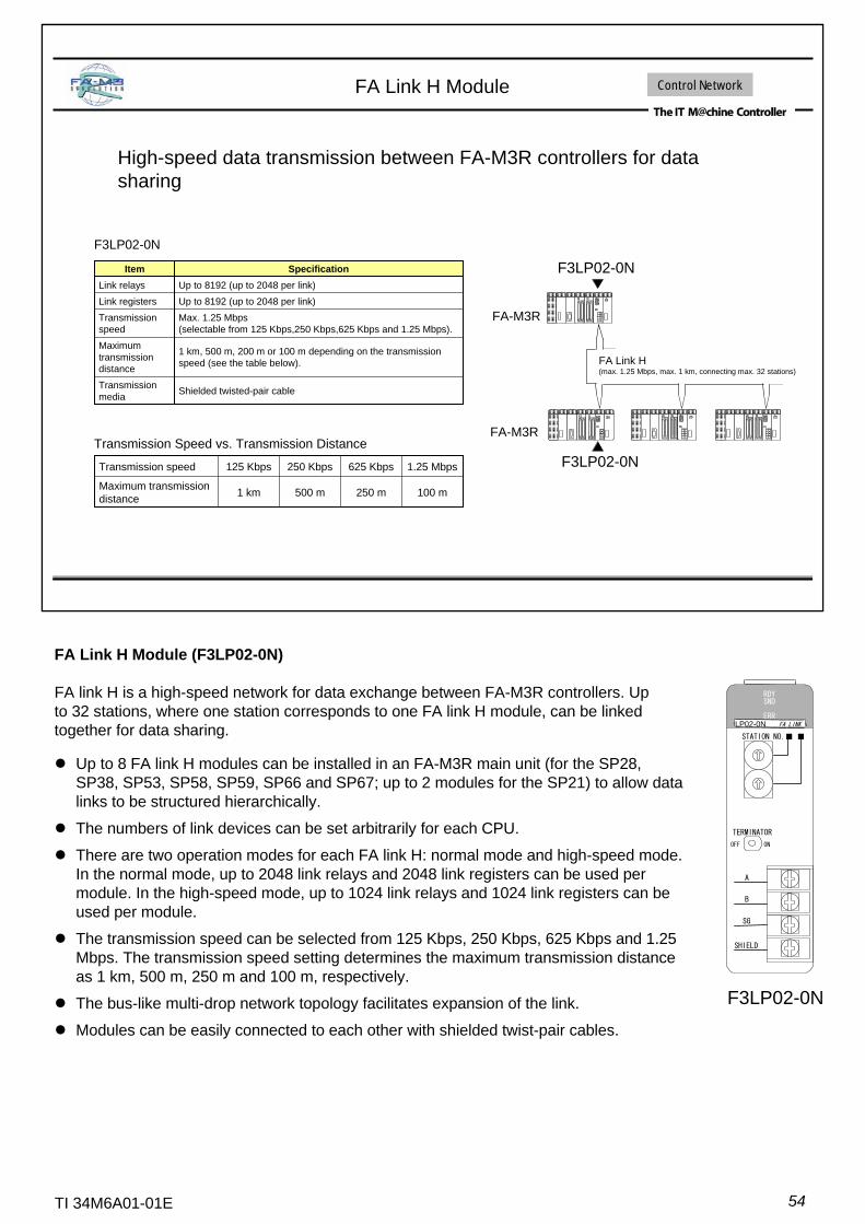
54TI 34M6A01-01E
High-speed data transmission between FA-M3R controllers for data sharing
FA Link H Module
F3LP02-0N
Transmission Speed vs. Transmission Distance
FA Link H (max. 1.25 Mbps, max. 1 km, connecting max. 32 stations)
F3LP02-0N
F3LP02-0N
FA-M3R
FA-M3R
Shielded twisted-pair cableTransmission media
1 km, 500 m, 200 m or 100 m depending on the transmission speed (see the table below).
Maximum transmission distance
Max. 1.25 Mbps (selectable from 125 Kbps,250 Kbps,625 Kbps and 1.25 Mbps).
Transmission speed
Up to 8192 (up to 2048 per link)Link registersUp to 8192 (up to 2048 per link)Link relays
SpecificationItem
100 m250 m500 m1 kmMaximum transmission distance
1.25 Mbps625 Kbps250 Kbps125 KbpsTransmission speed
Control Network
FA Link H Module (F3LP02-0N)
FA link H is a high-speed network for data exchange between FA-M3R controllers. Up to 32 stations, where one station corresponds to one FA link H module, can be linked together for data sharing.
Up to 8 FA link H modules can be installed in an FA-M3R main unit (for the SP28, SP38, SP53, SP58, SP59, SP66 and SP67; up to 2 modules for the SP21) to allow data links to be structured hierarchically.
The numbers of link devices can be set arbitrarily for each CPU.
There are two operation modes for each FA link H: normal mode and high-speed mode. In the normal mode, up to 2048 link relays and 2048 link registers can be used per module. In the high-speed mode, up to 1024 link relays and 1024 link registers can be used per module.
The transmission speed can be selected from 125 Kbps, 250 Kbps, 625 Kbps and 1.25 Mbps. The transmission speed setting determines the maximum transmission distance as 1 km, 500 m, 250 m and 100 m, respectively.
The bus-like multi-drop network topology facilitates expansion of the link.
Modules can be easily connected to each other with shielded twist-pair cables.
STATION NO.■ ■
TERMINATOR
OFF ON
SG
SHIELD
B
A
RDYSND
ERRLP02-0N FA LINK
F3LP02-0N
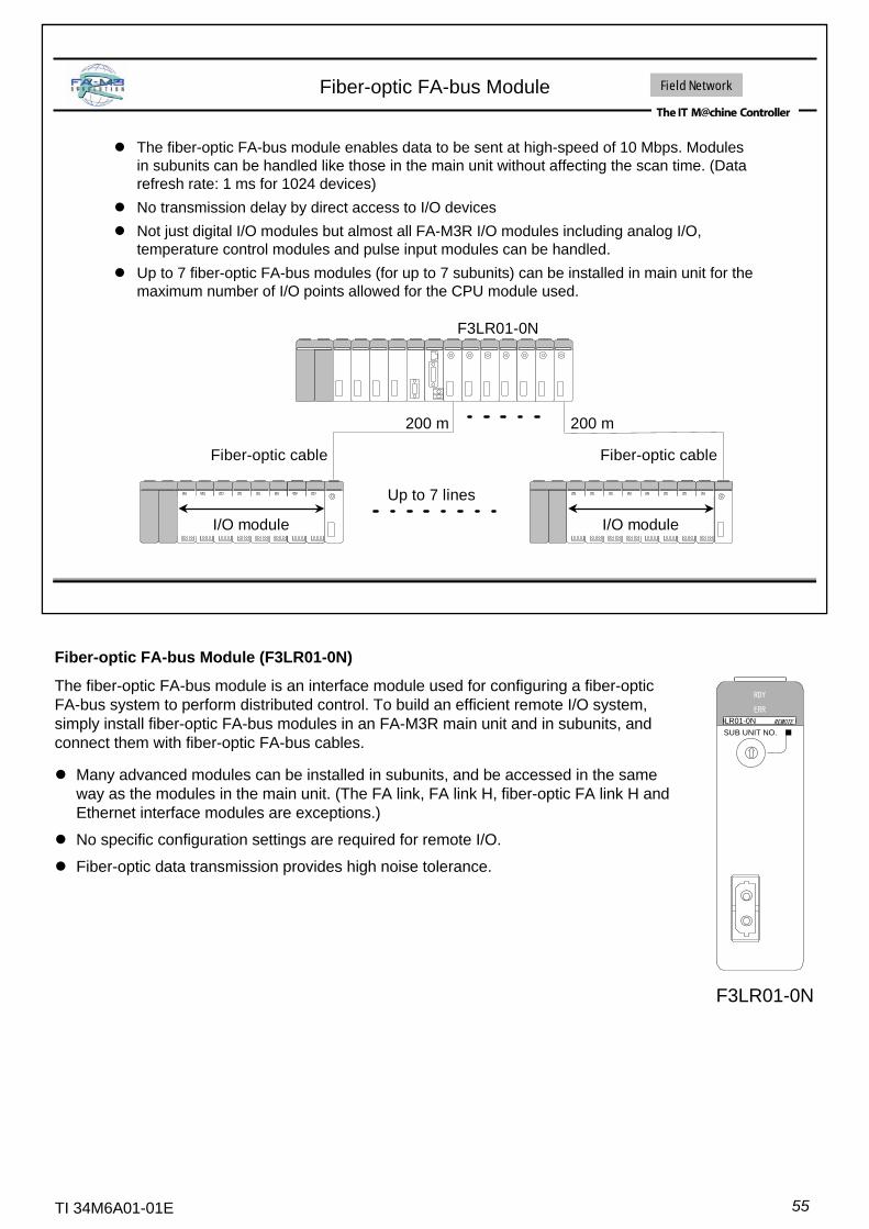
55TI 34M6A01-01E
The fiber-optic FA-bus module enables data to be sent at high-speed of 10 Mbps. Modules in subunits can be handled like those in the main unit without affecting the scan time. (Data refresh rate: 1 ms for 1024 devices)No transmission delay by direct access to I/O devicesNot just digital I/O modules but almost all FA-M3R I/O modules including analog I/O, temperature control modules and pulse input modules can be handled.Up to 7 fiber-optic FA-bus modules (for up to 7 subunits) can be installed in main unit for the maximum number of I/O points allowed for the CPU module used.
Fiber-optic FA-bus Module
I/O module
Fiber-optic cable
I/O module
Fiber-optic cable
Up to 7 lines
200 m 200 m
F3LR01-0N
Field Network
Fiber-optic FA-bus Module (F3LR01-0N)
The fiber-optic FA-bus module is an interface module used for configuring a fiber-optic FA-bus system to perform distributed control. To build an efficient remote I/O system, simply install fiber-optic FA-bus modules in an FA-M3R main unit and in subunits, and connect them with fiber-optic FA-bus cables.
Many advanced modules can be installed in subunits, and be accessed in the same way as the modules in the main unit. (The FA link, FA link H, fiber-optic FA link H and Ethernet interface modules are exceptions.)
No specific configuration settings are required for remote I/O.
Fiber-optic data transmission provides high noise tolerance.
RDY
ERR
LR01-0N REMOTE
SUB UNIT NO. ■
F3LR01-0N
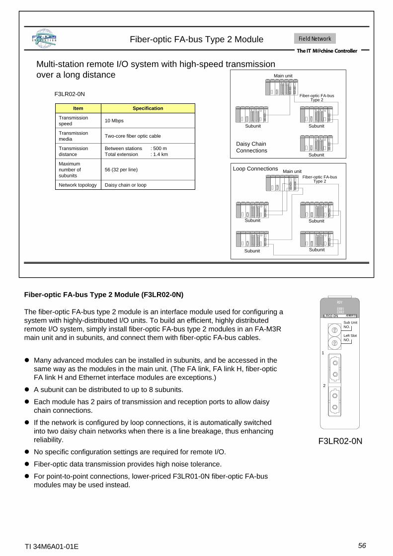
56TI 34M6A01-01E
Multi-station remote I/O system with high-speed transmission over a long distance
Fiber-optic FA-bus Type 2 Module
F3LR02-0N
Main unit
Fiber-optic FA-busType 2
Daisy ChainConnections
Subunit
Main unitFiber-optic FA-bus
Type 2
Loop Connections
Subunit
Subunit
Subunit Subunit
SubunitSubunit
Field Network
Daisy chain or loopNetwork topology
56 (32 per line)Maximum number of subunits
Between stations : 500 mTotal extension : 1.4 km
Transmission distance
Two-core fiber optic cableTransmission media
10 MbpsTransmission speed
SpecificationItem
Fiber-optic FA-bus Type 2 Module (F3LR02-0N)
The fiber-optic FA-bus type 2 module is an interface module used for configuring a system with highly-distributed I/O units. To build an efficient, highly distributedremote I/O system, simply install fiber-optic FA-bus type 2 modules in an FA-M3R main unit and in subunits, and connect them with fiber-optic FA-bus cables.
Many advanced modules can be installed in subunits, and be accessed in the same way as the modules in the main unit. (The FA link, FA link H, fiber-optic FA link H and Ethernet interface modules are exceptions.)
A subunit can be distributed to up to 8 subunits.
Each module has 2 pairs of transmission and reception ports to allow daisy chain connections.
If the network is configured by loop connections, it is automatically switched into two daisy chain networks when there is a line breakage, thus enhancing reliability.
No specific configuration settings are required for remote I/O.
Fiber-optic data transmission provides high noise tolerance.
For point-to-point connections, lower-priced F3LR01-0N fiber-optic FA-bus modules may be used instead.
Sub UnitNO.
RDY
ERR2LR02-0N REMORTE
Left SlotNO.
ERR1
1
2
F3LR02-0N
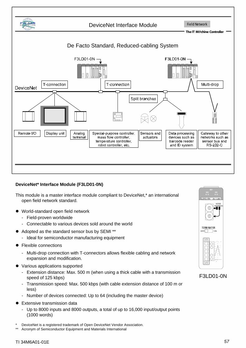
57TI 34M6A01-01E
DeviceNet Interface Module
De Facto Standard, Reduced-cabling System
Field Network
DeviceNet* Interface Module (F3LD01-0N)
This module is a master interface module compliant to DeviceNet,* an international open field network standard.
World-standard open field network- Field-proven worldwide- Connectable to various devices sold around the world
Adopted as the standard sensor bus by SEMI **- Ideal for semiconductor manufacturing equipment
Flexible connections
- Multi-drop connection with T-connectors allows flexible cabling and network expansion and modification.
Various applications supported- Extension distance: Max. 500 m (when using a thick cable with a transmission
speed of 125 kbps)- Transmission speed: Max. 500 kbps (with cable extension distance of 100 m or
less)- Number of devices connected: Up to 64 (including the master device)
Extensive transmission data- Up to 8000 inputs and 8000 outputs, a total of up to 16,000 input/output points
(1000 words)
* DeviceNet is a registered trademark of Open DeviceNet Vendor Association.** Acronym of Semiconductor Equipment and Materials International
F3LD01-0N
LD01-0N DeviceNet
NODEADDRESS
MS NS
TERMINATOROFF ON
RDY
◎ ◎ ◎ ◎

58TI 34M6A01-01E
YHLS Master Module and Slave Units
High-speed remote I/O providing flexibility for development, production and maintenance
Field Network
Info. network: Ethernet, ADS-net
Control network: FL-net
Sensors & peripherals network: DeviceNet, Asi, MECHATROLINK-II, PROFIBUS-DP
Bit reduced wiring: Anywire
G/WHigh-speed remote I/O: YHLS
F3LH01-1N F3LH02-1N
YHLS Master Module – F3LH01-1N, F3LH02-1NFast- Up to 12 Mbps. Scans 63 slave units in just 0.96 ms in full-duplex mode.- High-speed scan of 243 ms per 256 I/O pointsCompact- Slave unit size is halved (32-point slave the same size as competitors’ 16-point slave.)Reliable- Guaranteed constant scan time
(not affected by noise and online connection/disconnection of slave units)- Protected against short-circuit of I/O power supply of slave. (Error is reported to master)- Protected against short-circuit of output terminals of slave unit.Maintainable- Both power and communication connectors of slave support insertion/removal of live wires.- Allows online replacement of slave units.- Supports maintenance of individual sensors (I/O is equipped with individual power and
ground signals and supports e-CON like wiring.)- Both master module and slave units have communications quality indicators.Open- Allows connection of third-party HLS devices.- Adopts “HLS” open protocol, allowing user development of proprietary slave units.
DescriptionSuffix CodeModel
16 TR outputs (source-type, with short-circuit protection), 24 V DC 0.1 A, MIL-3EBM16 TR outputs (sink-type, with short-circuit protection), 24 V DC 0.1 A, MIL-3EAM
TAHYD16
16 DC inputs (negative common), 24 V DC, MIL-3NEM16 DC inputs (positive common), 24 V DC, MIL-3PEM
TAHXD16
16 TR outputs (source-type, with short-circuit protection), 24 V DC 0.1 A, MIL16 DC inputs (negative common), 24 V DC, MIL
-3NBM
16 TR outputs (sink-type, with short-circuit protection), 24 V DC 0.1 A, MIL16 DC inputs (positive common), 24 V DC, MIL
-3PAMTAHWD32
YHLS Slave Units - TAH Series
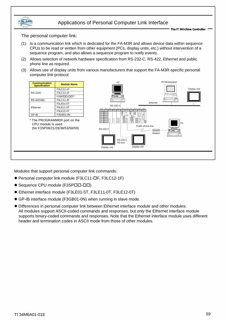
59TI 34M6A01-01E
The personal computer link:
(1) Is a communication link which is dedicated for the FA-M3R and allows device data within sequence CPUs to be read or written from other equipment (PCs, display units, etc.) without intervention of a sequence program, and also allows a sequence program to notify events.
(2) Allows selection of network hardware specification from RS-232-C, RS-422, Ethernet and public phone line as required.
(3) Allows use of display units from various manufacturers that support the FA-M3R-specific personal computer link protocol.
Applications of Personal Computer Link Interface
PC PC/Workstation
EthernetRS-232-C
RS-232-C
Display unit Display unit
RS-232-CRS-422
Public phone line
Modem
PC
F3GB01-0NGP-IBF3LE12-0TF3LE11-0TF3LE01-5T
Ethernet
F3LC11-2FRS-422/485F3SP - *1F3LC12-1FF3LC11-1F
RS-232C
Module NameCommunication Specification
Display unit
Modules that support personal computer link commands:
Personal computer link module (F3LC11- F, F3LC12-1F)
Sequence CPU module (F3SP - )
Ethernet interface module (F3LE01-5T, F3LE11-0T, F3LE12-0T)
GP-IB interface module (F3GB01-0N) when running in slave mode.
Differences in personal computer link between Ethernet interface module and other modules:All modules support ASCII-coded commands and responses, but only the Ethernet interface module supports binary-coded commands and responses. Note that the Ethernet interface module uses different header and termination codes in ASCII mode from those of other modules.
* The PROGRAMMER port on the CPU module is used. (for F3SP08/21/28/38/53/58/59)

60TI 34M6A01-01E
The built-in communications protocol allows connections to be made to other equipment that supports the same protocol without requiring any program, and facilitates system configuration. A personal computer link module is typically used to connect display units.
Personal Computer Link Modules
PC, Display Unit, etc.
Display Units, etc.
A personal computer link module provides the FA-M3R with the personal computer link feature via RS-232-C or RS-422/485.
F3LC11-2FF3LC11-1F (1 port)F3LC12-1F (2 ports)
RS-232-C
RS-422/485
FA-M3R
Peripheral Interface
Modem
Read/Write all devices in sequence CPU modules
Read/Write common variables in the BASIC CPU module
User program for data transmission is not needed. Devices can beread or written even if no ladder program is running.
Direct connection to a display unit having a programmable controller interface
Run/Stop a sequence CPU module remotely
Load/Save a sequence program
Read sequence program information such as program names, program size and block names, as well as error logs and user logs
An external modem can be optionally attached for use of PHS or mobile phone in locations with no 56 Kbps high-speed communication or telephone line. *1
Both ports can be used concurrently as personal computer links. *2
*1: For F3LC11-1F and F3LC12-1F only
*2: For F3LC12-1F only
LC11-2F C LINK
RDY
STATIONNO.■■
TERMINATOR
2- 4-WIRE
OFF
SD A
SD B
RD A
RD B
SG
SHIELD
F3LC11-1F (1 port) F3LC12-1F (2 ports)For RS-232-C
F3LC11-2FFor RS-422/485
LC12-1F C LINK
RDY
1
2
Personal Computer Link Modules (F3LC11-1F, F3LC11-2F and F3LC12-1F)

61TI 34M6A01-01E
A personal computer or display unit can be connected to the PROGRAMMER port of a sequence CPU module, providing an instant and low-cost personal computer link.
Supports high-speed display units of up to 115 Kbps
Personal Computer Link via PROGRAMMER Port
RS-232-C
Display UnitFA-M3RF3SP -
The same commands used for personal computer link modules are used with the sequence CPU modules.
Note: The following cables are available for connection from Yokogawa.
Model: KM11-2TSpecification: D-sub 9-pin female; approx. 3 meters long
Model : KM10C-0CSpecification : D-sub 9-pin female; approx. 0.5 meter long
Note: For details, see the General Specifications, FA-M3 CPU Port Cables (GS 34M6C91-01E).
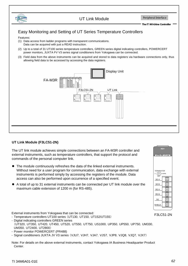
62TI 34M6A01-01E
Easy Monitoring and Setting of UT Series Temperature ControllersFeatures:(1) Data access from ladder programs with transparent communications.
Data can be acquired with just a READ instruction.(2) Up to a total of 31 UT100 series temperature controllers, GREEN series digital indicating controllers, POWERCERT
power monitors, JUXTA FV V3 series signal conditioners from Yokogawa can be connected.(3) Field data from the above instruments can be acquired and stored to data registers via hardware connections only, thus
allowing field data to be accessed by accessing the data registers.
UT Link Module
FA-M3R
F3LC51-2N UT Link
Display Unit
Peripheral Interface
UT Link Module (F3LC51-2N)
The UT link module achieves simple connections between an FA-M3R controller and external instruments, such as temperature controllers, that support the protocol and commands of the personal computer link.
The module continuously refreshes the data of the linked external instruments. Without need for a user program for communication, data exchange with external instruments is performed simply by accessing the registers of the module. Data access can also be performed upon occurrence of a specified event.
A total of up to 31 external instruments can be connected per UT link module over the maximum cable extension of 1200 m (for RS-485).
LC51-2N UT LINK
RDY
TERMINATOR
2- 4-WIRE
OFF
SD A
SD B
RD A
RD B
SG
SHIELD
F3LC51-2NExternal instruments from Yokogawa that can be connected:- Temperature controllers UT100 series (UT130,UT150,UT152/UT155)- Digital indicating controllers GREEN series(UT320,UT350,UT420,UT450,UT520,UT550,UT750,US1000,UP350,UP550,UP750,UM330,UM350,UT2400,UT2800)
- Power monitor POWERCERT (PR488)- Signal conditioners JUXTA JV V3 series (VJU7,VJH7,VJA7,VJS7,VJP8,VJQ8,VJQ7,VJX7)
Note: For details on the above external instruments, contact Yokogawa IA Business Headquarter Product Center.
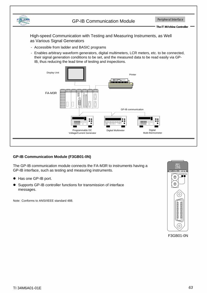
63TI 34M6A01-01E
GP-IB Communication Module
High-speed Communication with Testing and Measuring Instruments, as Well as Various Signal Generators- Accessible from ladder and BASIC programs- Enables arbitrary waveform generators, digital multimeters, LCR meters, etc. to be connected,
their signal generation conditions to be set, and the measured data to be read easily via GP-IB, thus reducing the lead time of testing and inspections.
Programmable DCVoltage/Current Generator
Display UnitPrinter
Digital Multimeter DigitalMulti-thermometer
FA-M3R
GP-IB communication
Peripheral Interface
GP-IB Communication Module (F3GB01-0N)
The GP-IB communication module connects the FA-M3R to instruments having a GP-IB interface, such as testing and measuring instruments.
Note: Conforms to ANSI/IEEE standard 488.
Has one GP-IB port.
Supports GP-IB controller functions for transmission of interface messages.
ADDRESS
RDYTALKLSTN
GB01-0N GP-IB
F3GB01-0N
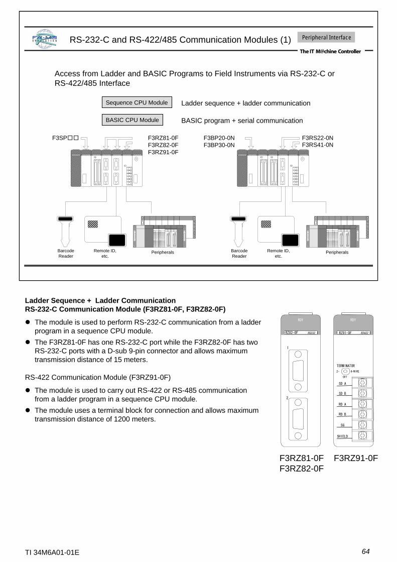
64TI 34M6A01-01E
Access from Ladder and BASIC Programs to Field Instruments via RS-232-C or RS-422/485 Interface
RS-232-C and RS-422/485 Communication Modules (1)
Sequence CPU Module Ladder sequence + ladder communication
BASIC CPU Module BASIC program + serial communication
Barcode Reader
Remote ID, etc.
Barcode Reader
Remote ID, etc.
Peripherals Peripherals
F3SP□□ F3BP20-0NF3BP30-0N
F3RZ81-0FF3RZ82-0FF3RZ91-0F
F3RS22-0NF3RS41-0N
Peripheral Interface
Ladder Sequence + Ladder CommunicationRS-232-C Communication Module (F3RZ81-0F, F3RZ82-0F)
The module is used to perform RS-232-C communication from a ladder program in a sequence CPU module.The F3RZ81-0F has one RS-232-C port while the F3RZ82-0F has two RS-232-C ports with a D-sub 9-pin connector and allows maximum transmission distance of 15 meters.
RS-422 Communication Module (F3RZ91-0F)
The module is used to carry out RS-422 or RS-485 communication from a ladder program in a sequence CPU module.The module uses a terminal block for connection and allows maximum transmission distance of 1200 meters.
RZ91-0F RS422
RDY
TERMINATOR
2- 4-WIRE
OFF
SD A
SD B
RD A
RD B
SG
SHIELD
RDY
RZ82-0F RS232
F3RZ91-0FF3RZ81-0FF3RZ82-0F
1
2

65TI 34M6A01-01E
Accessing from a Ladder Sequence Program by Combination of a Sequence CPU Module and a Ladder Communication Module
RS-232-C and RS-422 Communication Modules (2)
Accessing from a BASIC Program by Combination of a BASIC CPU Module and a Serial Communication Module
Peripheral Interface
BASIC Program + Serial CommunicationRS-232-C Communication Module (F3RS22-0N)
The F3RS22-0N module is used to carry out RS-232-C communication from a BASIC program running on a BASIC CPU module.The module has two RS-232-C ports with D-sub 9-pin connectors and allows the maximum transmission distance of 15 meters.BASIC statements for transmission and reception to/from communication lines are provided.
Note: This module is dedicated for use with a BASIC CPU module.
RS-422 Communication Module (F3RS41-0N)
The F3RS41-0N module is used to carry out RS-422 or RS-485 communication from a BASIC program running on a BASIC CPU module.The module uses a terminal block for connection and allows maximum transmission distance of 1200 meters.BASIC statements for data transmission and reception to/from thecommunication lines are provided.
RS41-0N RS422
RDY
TERMINATOR
2- 4-WIRE
OFF
SD A
SD B
RD A
RD B
SG
SHIELD
RDY
RS22-0N RS232
2
1
Note: This module is dedicated for use with a BASIC CPU module.
F3RS22-0N F3RS41-0N
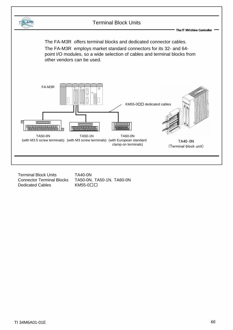
66TI 34M6A01-01E
Terminal Block Units
The FA-M3R offers terminal blocks and dedicated connector cables. The FA-M3R employs market standard connectors for its 32- and 64-point I/O modules, so a wide selection of cables and terminal blocks from other vendors can be used.
TA40‐0N(Terminal block unit)
FA-M3R
KM55-0 dedicated cables
TA50-0N(with M3.5 screw terminals)
TA50-1N(with M3 screw terminals)
TA60-0N(with European standard
clamp-on terminals)
Terminal Block Units TA40-0NConnector Terminal Blocks TA50-0N,TA50-1N,TA60-0NDedicated Cables KM55-0□□
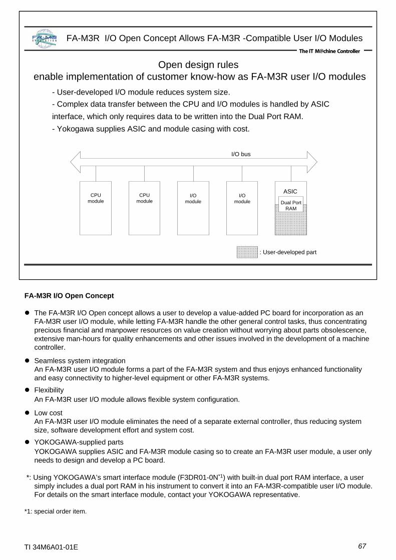
67TI 34M6A01-01E
Open design rules enable implementation of customer know-how as FA-M3R user I/O modules
ASICCPU
module
: User-developed part
CPUmodule
I/Omodule
I/Omodule Dual Port
RAM
I/O bus
- User-developed I/O module reduces system size.- Complex data transfer between the CPU and I/O modules is handled by ASIC interface, which only requires data to be written into the Dual Port RAM.- Yokogawa supplies ASIC and module casing with cost.
FA-M3R I/O Open Concept Allows FA-M3R -Compatible User I/O Modules
FA-M3R I/O Open Concept
The FA-M3R I/O Open concept allows a user to develop a value-added PC board for incorporation as an FA-M3R user I/O module, while letting FA-M3R handle the other general control tasks, thus concentrating precious financial and manpower resources on value creation without worrying about parts obsolescence, extensive man-hours for quality enhancements and other issues involved in the development of a machine controller.
Seamless system integrationAn FA-M3R user I/O module forms a part of the FA-M3R system and thus enjoys enhanced functionality and easy connectivity to higher-level equipment or other FA-M3R systems.
FlexibilityAn FA-M3R user I/O module allows flexible system configuration.
Low costAn FA-M3R user I/O module eliminates the need of a separate external controller, thus reducing system size, software development effort and system cost.
YOKOGAWA-supplied partsYOKOGAWA supplies ASIC and FA-M3R module casing so to create an FA-M3R user module, a user only needs to design and develop a PC board.
*: Using YOKOGAWA’s smart interface module (F3DR01-0N*1) with built-in dual port RAM interface, a user simply includes a dual port RAM in his instrument to convert it into an FA-M3R-compatible user I/O module. For details on the smart interface module, contact your YOKOGAWA representative.
*1: special order item.

68TI 34M6A01-01E
Reduced Wiring System
*1: For Fiber-optic FA bus 2, max. distance between stations is 500 mand max. total distance is 1.4 km, 32 stations per system
Distributed I/O to required locationsReduced wiring costNo communication program needed
Reduced wiring within panel or equipmentD/IO,A/IOTwist-pair cable500m,
63 stationsHigh-speedSAVE NET
Transmission within factoryD/IO,A/IOTwist-pair cable2km,
128 stationsLong-distance with many nodesVity Liner
Reduced wiring within panel
Uni-wire(D/IO, manifold)4-wire cabtire cable200m,
20 stationsHigh-speedUni-wire system
Reduced wiring within panel or factory
D/IO, various instruments, sensors, actuators
5-wire dedicated cable
500m,64 nodesHigh-speedDeviceNet
Transmission within panel
FA-M3R (D/IO, A/IO, pulse, temperature control)
Dedicated fiber-optic cable
500m, 56 stations*1
Ultra-high speed,Diverse I/O
Fiber-optic FA bus 2 system
Transmission within panel
FA-M3R (D/IO, A/IO, pulse, temperature control)
Dedicated fiber-optic cable
200m, 7 stations
Ultra-high speed,Diverse I/O
Fiber-optic FA bus system
Recommended usageI/O TypesTransmission cableDistance/No. of nodesFeaturesMethod

Windows and Excel are registered trademarks of Microsoft Corporation.Intel, MMX, and Pentium are trademarks or registered trademarks of Intel Corporation.Ethernet is a registered trademark of XEROX Corporation.Other product and company names appearing in this document are trademarks or registered trademarks of their respective holders.
TI 34M6A01-01E