Embed Size (px)
Citation preview
STREET DESIGN MANUALRALEIGH, NORTH CAROLINA
JANUARY, 2014
RESOLUTION NO. 2013 – 851
A RESOLUTION TO ADOPT THE RALEIGH STREET DESIGN MANUAL AND REPEAL THE STREETS, SIDEWALKS AND DRIVEWAY ACCESS HANDBOOK
WHEREAS, the Raleigh Street Design Manual is an adjunct to the recently adopted Unified Development Ordinance; and
WHEREAS, the Manual provides technical specifications used in construction of public improvements; and
WHEREAS, many of the technical specifications are engineering based standards that are not appropriate for inclusion in the Unified Development Ordinance; and
WHEREAS, the Manual will replace the existing Streets, Sidewalks and Driveway Access Handbook; and
WHEREAS, these enhancements were reviewed and discussed with public input.
NOW, THEREFORE, BE IT RESOLVED BY THE CITY COUNCIL OF RALEIGH, NORTH CAROLINA:
Section 1. The Raleigh Street Design Manual dated November 6, 2013 together with the Planning Commission recommendations dated August 13, 2013 contained in certified recommendation number CR-11547, are hereby adopted.
Section 2. The Raleigh Street Design Manual shall be effective five days after the adoption of this resolution.
Section 3. The Streets, Sidewalk and Driveway Access Handbook is hereby repealed coincident with the adoption of the Raleigh Street Design Manual.
Section 4. The Raleigh Street Design Manual is incorporated by the Unified Development Ordinance, Part 10A of the City Code.
Section 5. Except as otherwise authorized in this section, changes to the Raleigh Street Design Manual shall be approved by the City Council after a public hearing. The following changes may be made by staff without need for a City Council public hearing:
a. Technical corrections to illustrations where standards are not altered.
b. Correction of typographical errors, erroneous information or the addition of or alteration to references to external forms, applications or other governmental information.
c. Updates that are a result of recently adopted reference manuals required by Federal or State law.
d. The addition of any City Council-adopted alternative street cross section or public improvement related to specific capital improvement projects or streetscape plans or projects. This shall include street right-of-way width, location and dimension of all components contained within the right-of-way, street furniture elements, pavement treatment, pedestrian lighting, tree lawn and sidewalks.
e. Formatting and publication of the document where content is not altered.
Adopted: November 19, 2013
Effective: November 24, 2013
Distribution: Planning – Silver, Bowers, Crane, Lamb, Daniel
Public Works – Dawson, McGee
Transcription Svcs – Taylor
S T R E E T D E S I G N M A N U A L Pu b l i c Wo r k s D e p a r t m e n t , C i t y o f R a l e i g h , N o r t h C a r o l i n a
iJ a n u a r y, 2 014
4.2. Local Streets . . . . . . . . . . . . . . . . . . . . . . . . . . . . . . . . . 114.2.1. Neighborhood Yield 12
4.2.2. Neighborhood Local 13
4.2.3. Neighborhood Street 14
4.2.4. Multifamily Street 15
4.3. Mixed Use Streets . . . . . . . . . . . . . . . . . . . . . . . . . . . . . .164.3.1. Avenue 2-Lane, Undivided or Divided 17
4.3.2. Avenue 3-Lane, Parallel Parking 18
4.3.3. Main Street, Parallel or Angular Parking 19
4.4. Major Streets . . . . . . . . . . . . . . . . . . . . . . . . . . . . . . . . 204.4.1. Avenue 4-Lane, Parallel Parking 21
4.4.2. Avenue 4-Lane and 6-Lane, Divided 22
4.4.3. Multi-Way Boulevard, Parallel Parking or Angular Parking 23
4.5. Industrial and Service Streets . . . . . . . . . . . . . . . . . . . . . .244.5.1. Industrial Street 25
4.5.2. Alley, Residential (Private) 26
4.5.3. Alley, Mixed Use (Private) 26
4.6. Private Accessways . . . . . . . . . . . . . . . . . . . . . . . . . . . . . 274.6.1. Primary Internal Access Drive 27
4.6.2. Pedestrian Passage 28
SECTION 5. ADMINISTRATIVE PROCEDURES AND POLICIES5.1. Administrative Design Adjustment . . . . . . . . . . . . . . . . . . .29
5.1.1. Blocks, Lots, Access 29
5.1.2. New Streets 29
5.1.3. Existing Streets 29
SECTION 1. INTRODUCTION1.1. Purpose and Scope . . . . . . . . . . . . . . . . . . . . . . . . . . . . . . 1
SECTION 2. STREETS FOR ALL USERS2.1. Introduction . . . . . . . . . . . . . . . . . . . . . . . . . . . . . . . . . 2
2.2. Complete and Context Sensitive Streets . . . . . . . . . . . . . . . . 2
2.3. Process of Street Design . . . . . . . . . . . . . . . . . . . . . . . . . 3
2.4. Raleigh Standard Street Typologies . . . . . . . . . . . . . . . . . . 3
SECTION 3. STREET ELEMENT OVERVIEW3.1. Streetscape . . . . . . . . . . . . . . . . . . . . . . . . . . . . . . . . . . 4
3.2. Travelway . . . . . . . . . . . . . . . . . . . . . . . . . . . . . . . . . . . 43.2.1. General Travel Lane 4
3.2.2. Bicycle Facility 4
3.2.3. Transit Facility 4
3.2.4. On-Street Parking 4
3.2.5. Gutter and/or Shoulder 4
3.2.6. Median 5
3.2.7. Turn Lane 5
3.3. Roadway Classification Design Vehicle Type . . . . . . . . . . . . . 5
SECTION 4. STREET TYPES OVERVIEW4.1. Sensitive Area Streets . . . . . . . . . . . . . . . . . . . . . . . . . . . 7
4.1.1. Sensitive Area Parkway 8
4.1.2. Sensitive Area Avenue 9
4.1.3. Sensitive Area Residential Street 10
Contents
S T R E E T D E S I G N M A N U A L Pu b l i c Wo r k s D e p a r t m e n t , C i t y o f R a l e i g h , N o r t h C a r o l i n a
iiJ a n u a r y, 2 014
SECTION 6. PLANNING AND DESIGN CRITERIA6.1. Connectivity . . . . . . . . . . . . . . . . . . . . . . . . . . . . . . . . . 37
6.2. Vehicular Access . . . . . . . . . . . . . . . . . . . . . . . . . . . . . . .38
6.3. Pedestrian Access . . . . . . . . . . . . . . . . . . . . . . . . . . . . . .38
6.4. Sidewalks . . . . . . . . . . . . . . . . . . . . . . . . . . . . . . . . . . .386.4.1. Sidewalk Access Ramps 39
6.4.2. ADA Requirements 39
6.5. Driveway Access Points . . . . . . . . . . . . . . . . . . . . . . . . . .396.5.1. Driveway Dimensions 39
6.5.2. Driveways for Residential Uses 40
6.5.3. Driveways for Mixed Use and Nonresidential Uses 40
6.5.4. Residential Development Access 40
6.5.5. Driveway Type 40
6.5.6. Alignment and Grades 40
6.5.7. Plot plan criteria for residential driveway approvals 41
6.5.8. Commercial Development Access 41
6.6. Curb and Gutter . . . . . . . . . . . . . . . . . . . . . . . . . . . . . . .42
6.7. Roadway Improvements . . . . . . . . . . . . . . . . . . . . . . . . . .42
6.8. Roadway Layout . . . . . . . . . . . . . . . . . . . . . . . . . . . . . . .426.8.1. Street Intersection Design 42
6.9. Cul-de-sac Design . . . . . . . . . . . . . . . . . . . . . . . . . . . . . .44
6.10. Horizontal Street Design . . . . . . . . . . . . . . . . . . . . . . . .44
6.11. Vertical Street Design . . . . . . . . . . . . . . . . . . . . . . . . . .44
6.12. Sight Distance . . . . . . . . . . . . . . . . . . . . . . . . . . . . . . . .466.12.1. Stopping Sight Distance 46
6.12.2. Intersection Sight Distance 47
6.12.3. Sight Distance Note applicable to all Plans 48
5.2. Encroachments in the Right-of-Way . . . . . . . . . . . . . . . . . . . 305.2.1. Major Encroachments 30
5.2.2. Minor Encroachments 30
5.3. Infrastructure Requirements . . . . . . . . . . . . . . . . . . . . . .305.3.1. Infrastructure Sufficiency 30
5.3.2. Roadway Construction Through and Adjoining Developments 30
5.3.3. Minimum Paving Construction 30
5.3.4. Fee in Lieu 31
5.3.5. Exemptions to Fee in Lieu and pavement construction 31
5.4. Infrastructure Construction Plans . . . . . . . . . . . . . . . . . . 32
5.5. Infrastructure Reimbursements . . . . . . . . . . . . . . . . . . . . . 325.5.1. Improvements Eligible for Reimbursement 32
5.5.2. Expiration of Reimbursement 32
5.6. Construction Surety . . . . . . . . . . . . . . . . . . . . . . . . . . . . 32
5.7. NCDOT Coordination . . . . . . . . . . . . . . . . . . . . . . . . . . . . 33
5.8. Public Street Right-of-Way Conveyance . . . . . . . . . . . . . . . . 335.8.1. Right-of-Way Widths 34
5.8.2. Coordination with Adopted Roadway Plans 35
5.8.3. Reservation Periods for Right-of-Way 35
5.8.4. Slope Easements 35
5.8.5. Adjustments to Required Right-of-Way Widths 35
5.9. Temporary ROW Closure for Public Streets & Sidewalks . . . . . 35
5.10. Right-of-Way Permits . . . . . . . . . . . . . . . . . . . . . . . . . . .365.10.1. Site Final 36
5.10.2. Construction Purposes 36
5.10.3. Driveway/Sidewalk 36
5.10.4. Street Cut permits (Permit to do work in the Public Right of Way) 36
5.10.5. Lane Closure Permit 36
S T R E E T D E S I G N M A N U A L Pu b l i c Wo r k s D e p a r t m e n t , C i t y o f R a l e i g h , N o r t h C a r o l i n a
i i iJ a n u a r y, 2 014
6.12.4. Objects permitted in the Sight Distance Triangle 48
6.13. Transition and Roadway Design . . . . . . . . . . . . . . . . . . . .486.13.1. Turn Lane Warrants 48
6.13.2. Turning Lanes 49
6.13.3. Total Length of Turn Lane 50
6.13.4. Turn Lane Storage -- Signalized Intersections 50
6.13.5. Turn Lane Storage – Non-signalized Intersections 51
6.13.6. Right-Turn / Deceleration Lengths 51
6.13.7. Tapers 51
6.14. Intersection Design and Operations . . . . . . . . . . . . . . . . . 516.14.1. Traffic Control Devices 51
6.14.2. Curb Return Radii 51
6.14.3. Pavement Markings 52
6.15. Private Streets . . . . . . . . . . . . . . . . . . . . . . . . . . . . . . . 526.15.1. General 52
6.16. Parking . . . . . . . . . . . . . . . . . . . . . . . . . . . . . . . . . . . . 536.16.1. Parking Lot Design and Layout (On-site Parking) 53
6.16.2. On-Street Parking (Public Parking Spaces) 54
6.17. Streetscape Design and Operations . . . . . . . . . . . . . . . . . .546.17.1. Streetscape 54
6.17.2. Adopted Streetscape Plans 55
6.18. Street Trees . . . . . . . . . . . . . . . . . . . . . . . . . . . . . . . . . 556.18.1. Street Tree Plantings in an Urban Setting 55
6.18.2. Tree Infrastructure, Installation and Maintenance Standards 56
6.19. Transit . . . . . . . . . . . . . . . . . . . . . . . . . . . . . . . . . . . .586.19.1. Overview 58
6.19.2. Planning Phase 58
6.19.3. Design Phase 59
6.20. Solid Waste Design . . . . . . . . . . . . . . . . . . . . . . . . . . . . .596.20.1. General Access Standards 59
6.20.2. Alley Access Standards 60
6.20.3. Residential Access Standards 60
6.21. Traffic Calming (Pending project approval) . . . . . . . . . . . . .61
6.22. Street Lights . . . . . . . . . . . . . . . . . . . . . . . . . . . . . . . .616.22.1. Lighting Design for City Maintained Streets 62
6.23. Traffic Studies . . . . . . . . . . . . . . . . . . . . . . . . . . . . . . .636.23.1. Purpose of Traffic Studies 63
6.23.2. Initiating Traffic Studies 64
6.23.3. Land Uses 64
6.23.4. Trip Generation 64
6.23.5. Site Context 64
6.23.6. Miscellaneous Applications 65
6.23.7. Study Area 65
6.23.8. Access Points and Intersections 65
6.23.9. Traffic Study Scope 65
6.23.10. Traffic Model Analysis Programs 65
6.23.11. Preferred Analysis Programs 66
6.23.12. Existing Conditions 66
6.23.13. Existing Conditions Data Requirements 66
6.23.14. Non-Site Traffic Forecast 66
6.23.15. Site Traffic Generation 67
6.23.16. Internal Capture Trips 67
6.23.17. Pass-by Trips 67
6.23.18. Alternative Mode Trips 67
6.23.19. Site Traffic Distribution and Assignment 67
S T R E E T D E S I G N M A N U A L Pu b l i c Wo r k s D e p a r t m e n t , C i t y o f R a l e i g h , N o r t h C a r o l i n a
ivJ a n u a r y, 2 014
6.23.20. Analysis 67
6.23.21. Measures of Effectiveness 68
6.23.22. Traffic Analysis Default Values 68
6.23.23. Traffic Impact Mitigation Measures 69
6.23.24. Traffic Study Report 69
6.23.25. Multimodal Analysis 69
6.23.26. Accident History 69
6.23.27. Traffic Study Conclusion and Recommendations 70
6.23.28. Traffic Study Submittal Requirements 70
6.24. Bicycle Infrastructure . . . . . . . . . . . . . . . . . . . . . . . . . . 706.24.1. Bike Parking Standards 70
6.24.2. On-Road Bicycle Facility Design Standards 72
SECTION 7. GLOSSARY 7.1. Defined Terms . . . . . . . . . . . . . . . . . . . . . . . . . . . . . . . . . 74
SECTION 8. STANDARD DETAIL DRAWINGS
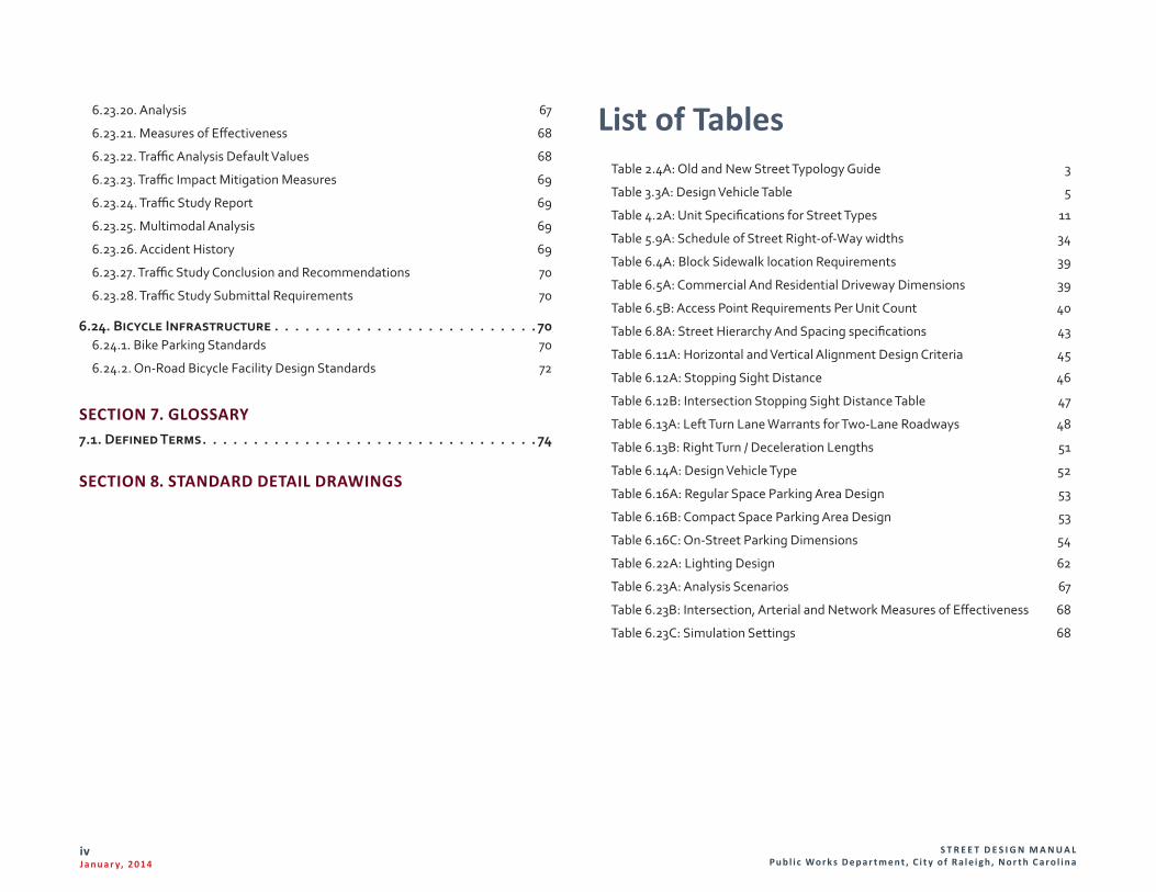
List of TablesTable 2.4A: Old and New Street Typology Guide 3
Table 3.3A: Design Vehicle Table 5
Table 4.2A: Unit Specifications for Street Types 11
Table 5.9A: Schedule of Street Right-of-Way widths 34
Table 6.4A: Block Sidewalk location Requirements 39
Table 6.5A: Commercial And Residential Driveway Dimensions 39
Table 6.5B: Access Point Requirements Per Unit Count 40
Table 6.8A: Street Hierarchy And Spacing specifications 43
Table 6.11A: Horizontal and Vertical Alignment Design Criteria 45
Table 6.12A: Stopping Sight Distance 46
Table 6.12B: Intersection Stopping Sight Distance Table 47
Table 6.13A: Left Turn Lane Warrants for Two-Lane Roadways 48
Table 6.13B: Right Turn / Deceleration Lengths 51
Table 6.14A: Design Vehicle Type 52
Table 6.16A: Regular Space Parking Area Design 53
Table 6.16B: Compact Space Parking Area Design 53
Table 6.16C: On-Street Parking Dimensions 54
Table 6.22A: Lighting Design 62
Table 6.23A: Analysis Scenarios 67
Table 6.23B: Intersection, Arterial and Network Measures of Effectiveness 68
Table 6.23C: Simulation Settings 68
S T R E E T D E S I G N M A N U A L Pu b l i c Wo r k s D e p a r t m e n t , C i t y o f R a l e i g h , N o r t h C a r o l i n a
1J a n u a r y, 2 014
Section 1. Introduction1.1. Purpose and ScopeA. This Manual has been developed in conjunction with the Unified Development
Ordinance, which recognizes the critical link between land use and transportation, insuring that both work together to preserve and create great places within the City of Raleigh.
B. In the case where any requirement in the City of Raleigh Code conflicts with any regulation or standard presented in this manual, the City of Raleigh Code shall control.
C. The design guidelines contained in this Manual are intended to provide for adequate and coordinated development with necessary facilities to serve and protect all users of Raleigh’s transportation system.
D. Staff will apply fundamental engineering principles and practices in the evaluation of the design and construction plans in review.
E. It is recognized that certain improvements financed wholly or in part with State and Federal funds are subject to the regulations and standards prescribed by those agencies. Such regulations and standards may be different than those of the City and may take priority over City regulations and standards presented in this manual. The guidance presented herein is based on nationally-accepted design parameters, including AASHTO’s A Policy on the Geometric Design of Highways and Streets and Flexibility in Highway Design, and supplemented by context-specific guidance such as that contained in the joint ITE/CNU Designing Walkable Urban Thoroughfares: A Context Sensitive Approach.
F. The Public Works Director, or his/her designee thereafter referred to as the Public Works Director, in consultation with other City departments and state agencies, may in accordance with Section 8.3.6 and 10.2.18 of the Unified Development Ordinance, approve design adjustments for identified regulations established in Chapter 8 of the Unified Development Ordinance.
S T R E E T D E S I G N M A N U A L Pu b l i c Wo r k s D e p a r t m e n t , C i t y o f R a l e i g h , N o r t h C a r o l i n a
2J a n u a r y, 2 014
2.2. Complete and Context Sensitive StreetsA. In 2009, NCDOT adopted a Complete Streets Policy. The Policy Statement is
cited for reference below:
Transportation, quality of life, and economic development are all undeniably connected through well-planned, well-designed, and context sensitive transportation solutions. To NCDOT, the designations “well-planned”, “well-designed” and “context-sensitive” imply that transportation is an integral part of a comprehensive network that safely supports the needs of the communities and the traveling public that are served.
The North Carolina Department of Transportation, in its role as stewards over the transportation infrastructure, is committed to:
§ Providing an efficient multi-modal transportation network in North Carolina such that the access, mobility, and safety needs of motorists, transit users, bicyclists, and pedestrians of all ages and abilities are safely accommodated;
§ Caring for the built and natural environments by promoting sustainable development practices that minimize impacts on natural resources, historic, businesses, residents, scenic and other community values, while also recognizing that transportation improvements have significant potential to contribute to local, regional, and statewide quality of life and economic development objectives;
§ Working in partnership with local government agencies, interest groups, and the public to plan, fund, design, construct, and manage complete street networks that sustain mobility while accommodating walking, biking, and transit opportunities safely.
This policy requires that NCDOT’s planners and designers will consider and incorporate multimodal alternatives in the design and improvement of all appropriate transportation projects within a growth area of a town or city unless exceptional circumstances exist. Routine maintenance projects may be excluded from this requirement; if an appropriate source of funding is not available.
Section 2. Streets for All Users2.1. IntroductionA. Raleigh’s Unified Development Ordinance, sets forth many street typologies to
work with various streetscapes and frontage types. While the UDO establishes the appropriate street typology, this manual assists with specific design details related to the engineering aspects of the various street typologies.
B. It is the responsibility of the developer to take future roadway plans of the City and NCDOT into consideration when developing a site plan for a future development. Sources of information include, but are not limited to:
1. The Arterials, Thoroughfares and Collector Streets Map and the Street Typology Map in the Transportation Element of Raleigh’s Comprehensive Plan
2. NCDOT Transportation Improvement Program (TIP)
3. Capital Improvement Plan (CIP)
4. City of Raleigh and Wake County Short and Long Range Transit Plans
5. CAMPO Metropolitan Transportation Plan (MTP)
6. City Council Authorized Roadway Projects
7. Approved Roadway Plans
8. Approved Corridor Plans
9. American Association of State and Highway and Transportation Officials (AASHTO)
10. Manual on Uniform Traffic Control Devices (MUTCD)
11. Public Right of Way Advisory Group (PROWAG)
12. American with Disability Accessible Design Requirements
C. In addition, character and circulation patterns of developments in the immediate vicinity should also be taken into consideration to address existing development patterns and context.
S T R E E T D E S I G N M A N U A L Pu b l i c Wo r k s D e p a r t m e n t , C i t y o f R a l e i g h , N o r t h C a r o l i n a
3J a n u a r y, 2 014
B. The City of Raleigh supports that complete streets as an important aspect of the quality of life in the City, and has therefore developed a palette of street typologies that accommodate all users within the context of the UDO. While the street typologies adhere to the principles of Complete Streets, some place more emphasis on moving vehicular traffic than others. Context and frontage type strongly influence the balance between various modes of transportation.
C. The sections contained herein were developed concurrently and in coordination with NCDOT’s Complete Streets Policy; however, in some instances, they may vary somewhat from the NCDOT sections in order to be consistent with a certain land use or development typology context.
2.3. Process of Street DesignStreets shall be designed to be consistent and supportive of their context, serving all modes of mobility which occur within that context in a safe and efficient manner.
2.4. Raleigh Standard Street TypologiesA. The street typologies, their primary functions and elements are defined herein.
Typical cross-sections are depicted with the acknowledgement that appropriate modifications to the preferred cross-sections and dimensions may be approved. Any deviations from the required dimensions must be approved by the Public Works Director as a Design Adjustment.
B. These street typologies are set forth in the UDO; however, this Manual provides the typologies with additional and more detailed engineering and technical specifications.
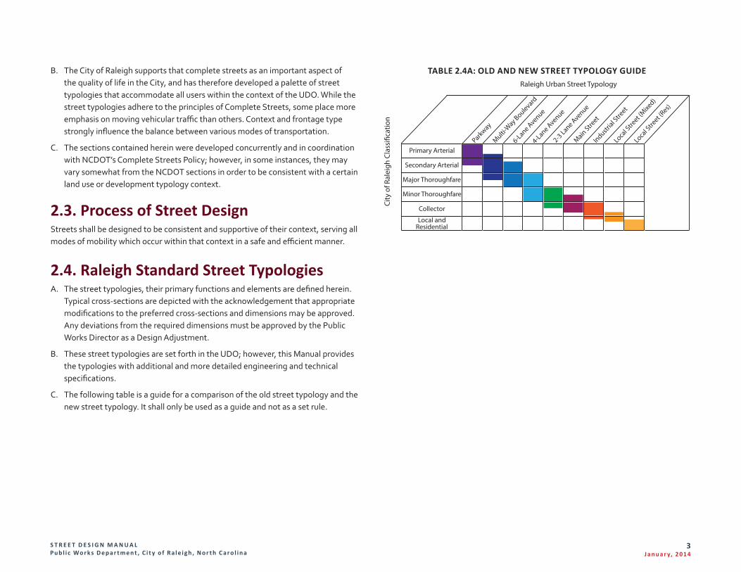
C. The following table is a guide for a comparison of the old street typology and the new street typology. It shall only be used as a guide and not as a set rule.
TABLE 2.4A: OLD AND NEW STREET TYPOLOGY GUIDE
Primary Arterial
Secondary Arterial
Major Thoroughfare
Minor Thoroughfare
Collector
Local andResidential
Parkway
6-Lane Avenue4-Lane Avenue2-3 Lane AvenueMain Stre
etIndustr
ial Stre
etLo
cal S
treet (
Mixed)
Loca
l Stre
et (Res)
Multi-Way Boulevard
Raleigh Urban Street Typology
City
of R
alei
gh C
lass
i�ca
tion
S T R E E T D E S I G N M A N U A L Pu b l i c Wo r k s D e p a r t m e n t , C i t y o f R a l e i g h , N o r t h C a r o l i n a
4J a n u a r y, 2 014
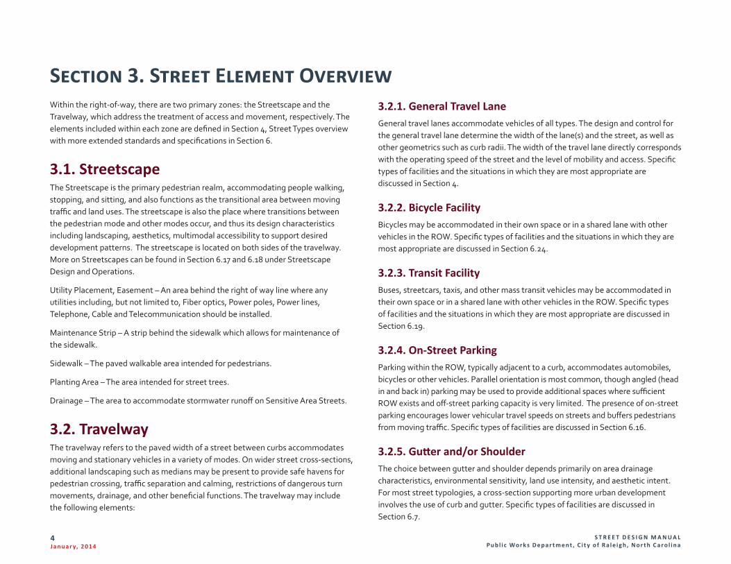
Section 3. Street Element Overview3.2.1. General Travel LaneGeneral travel lanes accommodate vehicles of all types. The design and control for the general travel lane determine the width of the lane(s) and the street, as well as other geometrics such as curb radii. The width of the travel lane directly corresponds with the operating speed of the street and the level of mobility and access. Specific types of facilities and the situations in which they are most appropriate are discussed in Section 4.
3.2.2. Bicycle FacilityBicycles may be accommodated in their own space or in a shared lane with other vehicles in the ROW. Specific types of facilities and the situations in which they are most appropriate are discussed in Section 6.24.
3.2.3. Transit FacilityBuses, streetcars, taxis, and other mass transit vehicles may be accommodated in their own space or in a shared lane with other vehicles in the ROW. Specific types of facilities and the situations in which they are most appropriate are discussed in Section 6.19.
3.2.4. On-Street ParkingParking within the ROW, typically adjacent to a curb, accommodates automobiles, bicycles or other vehicles. Parallel orientation is most common, though angled (head in and back in) parking may be used to provide additional spaces where sufficient ROW exists and off-street parking capacity is very limited. The presence of on-street parking encourages lower vehicular travel speeds on streets and buffers pedestrians from moving traffic. Specific types of facilities are discussed in Section 6.16.
3.2.5. Gutter and/or ShoulderThe choice between gutter and shoulder depends primarily on area drainage characteristics, environmental sensitivity, land use intensity, and aesthetic intent. For most street typologies, a cross-section supporting more urban development involves the use of curb and gutter. Specific types of facilities are discussed in Section 6.7.
Within the right-of-way, there are two primary zones: the Streetscape and the Travelway, which address the treatment of access and movement, respectively. The elements included within each zone are defined in Section 4, Street Types overview with more extended standards and specifications in Section 6.
3.1. StreetscapeThe Streetscape is the primary pedestrian realm, accommodating people walking, stopping, and sitting, and also functions as the transitional area between moving traffic and land uses. The streetscape is also the place where transitions between the pedestrian mode and other modes occur, and thus its design characteristics including landscaping, aesthetics, multimodal accessibility to support desired development patterns. The streetscape is located on both sides of the travelway. More on Streetscapes can be found in Section 6.17 and 6.18 under Streetscape Design and Operations.
Utility Placement, Easement – An area behind the right of way line where any utilities including, but not limited to, Fiber optics, Power poles, Power lines, Telephone, Cable and Telecommunication should be installed.
Maintenance Strip – A strip behind the sidewalk which allows for maintenance of the sidewalk.
Sidewalk – The paved walkable area intended for pedestrians.
Planting Area – The area intended for street trees.
Drainage – The area to accommodate stormwater runoff on Sensitive Area Streets.
3.2. TravelwayThe travelway refers to the paved width of a street between curbs accommodates moving and stationary vehicles in a variety of modes. On wider street cross-sections, additional landscaping such as medians may be present to provide safe havens for pedestrian crossing, traffic separation and calming, restrictions of dangerous turn movements, drainage, and other beneficial functions. The travelway may include the following elements:
S T R E E T D E S I G N M A N U A L Pu b l i c Wo r k s D e p a r t m e n t , C i t y o f R a l e i g h , N o r t h C a r o l i n a
5J a n u a r y, 2 014
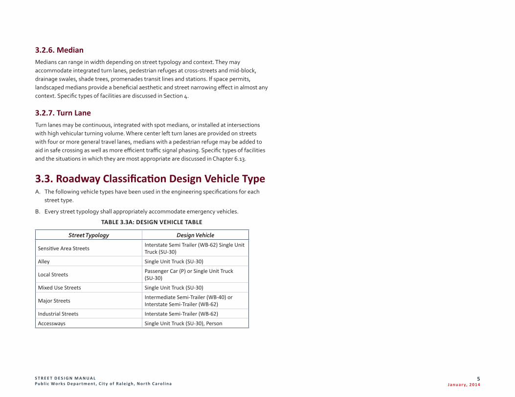
3.2.6. MedianMedians can range in width depending on street typology and context. They may accommodate integrated turn lanes, pedestrian refuges at cross-streets and mid-block, drainage swales, shade trees, promenades transit lines and stations. If space permits, landscaped medians provide a beneficial aesthetic and street narrowing effect in almost any context. Specific types of facilities are discussed in Section 4.
3.2.7. Turn LaneTurn lanes may be continuous, integrated with spot medians, or installed at intersections with high vehicular turning volume. Where center left turn lanes are provided on streets with four or more general travel lanes, medians with a pedestrian refuge may be added to aid in safe crossing as well as more efficient traffic signal phasing. Specific types of facilities and the situations in which they are most appropriate are discussed in Chapter 6.13.
3.3. Roadway Classification Design Vehicle TypeA. The following vehicle types have been used in the engineering specifications for each
street type.
B. Every street typology shall appropriately accommodate emergency vehicles.
TABLE 3.3A: DESIGN VEHICLE TABLE
Street Typology Design Vehicle
Sensitive Area Streets Interstate Semi Trailer (WB-62) Single Unit Truck (SU-30)
Alley Single Unit Truck (SU-30)
Local Streets Passenger Car (P) or Single Unit Truck (SU-30)
Mixed Use Streets Single Unit Truck (SU-30)
Major Streets Intermediate Semi-Trailer (WB-40) or Interstate Semi-Trailer (WB-62)
Industrial Streets Interstate Semi-Trailer (WB-62)
Accessways Single Unit Truck (SU-30), Person
S T R E E T D E S I G N M A N U A L Pu b l i c Wo r k s D e p a r t m e n t , C i t y o f R a l e i g h , N o r t h C a r o l i n a
6J a n u a r y, 2 014
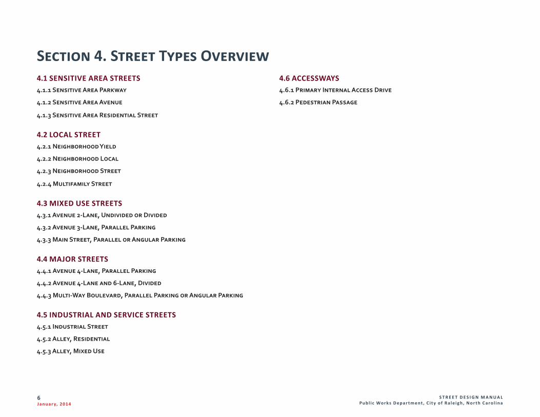
Section 4. Street Types Overview4.6 ACCESSWAYS4.6.1 Primary Internal Access Drive
4.6.2 Pedestrian Passage
4.1 SENSITIVE AREA STREETS 4.1.1 Sensitive Area Parkway
4.1.2 Sensitive Area Avenue
4.1.3 Sensitive Area Residential Street
4.2 LOCAL STREET4.2.1 Neighborhood Yield
4.2.2 Neighborhood Local
4.2.3 Neighborhood Street
4.2.4 Multifamily Street
4.3 MIXED USE STREETS4.3.1 Avenue 2-Lane, Undivided or Divided
4.3.2 Avenue 3-Lane, Parallel Parking
4.3.3 Main Street, Parallel or Angular Parking
4.4 MAJOR STREETS4.4.1 Avenue 4-Lane, Parallel Parking
4.4.2 Avenue 4-Lane and 6-Lane, Divided
4.4.3 Multi-Way Boulevard, Parallel Parking or Angular Parking
4.5 INDUSTRIAL AND SERVICE STREETS4.5.1 Industrial Street
4.5.2 Alley, Residential
4.5.3 Alley, Mixed Use
S T R E E T D E S I G N M A N U A L Pu b l i c Wo r k s D e p a r t m e n t , C i t y o f R a l e i g h , N o r t h C a r o l i n a
7J a n u a r y, 2 014
4.1. Sensitive Area StreetsA. In areas of Raleigh where stormwater and wastewater do not feed into sewers,
other forms of drainage must be provided. Along encompassed streets, open channel drainage ditches are typical and must be accommodated within special cross-sections. The following roadway cross-sections are intended for use in these “Sensitive” areas.
1. Sensitive Area Parkways are semi-limited access corridors, and are often used to preserve scenic views. They are intended primarily to support regional travel. Medians are a standard feature of parkways in almost every case, except where a narrower cross-section is needed to minimize right-of-way and environmental impact.
2. Sensitive Area Avenues are for use in low-intensity areas that do not have sewer provisions. They have relatively narrow paved widths, which includes shoulders for bicycle and pedestrian uses in retrofit situations lacking sidewalks.
3. Sensitive Area Residential Streets are appropriate in rural conditions with large lot homes, without water and sewer provisions.
S T R E E T D E S I G N M A N U A L Pu b l i c Wo r k s D e p a r t m e n t , C i t y o f R a l e i g h , N o r t h C a r o l i n a
8J a n u a r y, 2 014
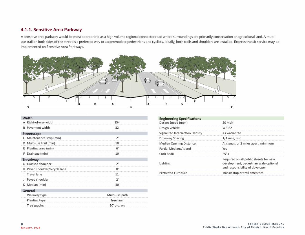
4.1.1. Sensitive Area ParkwayA sensitive area parkway would be most appropriate as a high volume regional connector road where surroundings are primarily conservation or agricultural land. A multi-use trail on both sides of the street is a preferred way to accommodate pedestrians and cyclists. Ideally, both trails and shoulders are installed. Express transit service may be implemented on Sensitive Area Parkways.
Width A Right-of-way width 154' B Pavement width 32'
StreetscapeC Maintenance strip (min) 2'D Multi-use trail (min) 10'E Planting area (min) 6'F Drainage (min) 10'
TravelwayG Grassed shoulder 2'H Paved shoulder/bicycle lane 8'I Travel lane 11' J Paved shoulder 2'K Median (min) 30'
General Walkway type Multi-use pathPlanting type Tree lawnTree spacing 50' o.c. avg
D IHF
HK
IF
E
A
DE CGG J J
B B
I IC
Engineering SpecificationsDesign Speed (mph) 50 mphDesign Vehicle WB-62Signalized Intersection Density As warrantedDriveway Spacing 1/4 mile, minMedian Opening Distance At signals or 2 miles apart, minimumPartial Medians/Island YesCurb Radii 25' +
LightingRequired on all public streets for new development, pedestrian scale optional and responsibility of developer
Permitted Furniture Transit stop or trail amenities
S T R E E T D E S I G N M A N U A L Pu b l i c Wo r k s D e p a r t m e n t , C i t y o f R a l e i g h , N o r t h C a r o l i n a
9J a n u a r y, 2 014
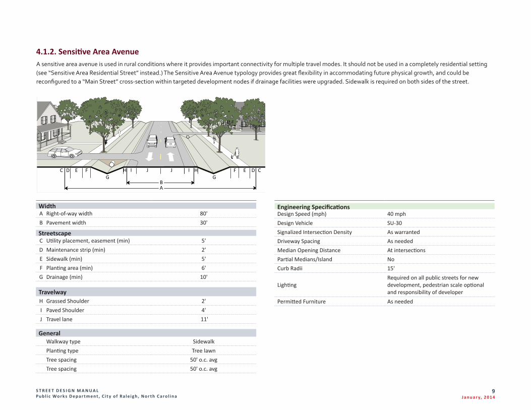
4.1.2. Sensitive Area AvenueA sensitive area avenue is used in rural conditions where it provides important connectivity for multiple travel modes. It should not be used in a completely residential setting (see “Sensitive Area Residential Street” instead.) The Sensitive Area Avenue typology provides great flexibility in accommodating future physical growth, and could be reconfigured to a “Main Street” cross-section within targeted development nodes if drainage facilities were upgraded. Sidewalk is required on both sides of the street.
WidthA Right-of-way width 80'B Pavement width 30'
StreetscapeC Utility placement, easement (min) 5'D Maintenance strip (min) 2'E Sidewalk (min) 5'F Planting area (min) 6'G Drainage (min) 10'
TravelwayH Grassed Shoulder 2'I Paved Shoulder 4'J Travel lane 11'
General Walkway type SidewalkPlanting type Tree lawnTree spacing 50' o.c. avgTree spacing 50' o.c. avg
EC J JI IG
FD HHG
AB
EF D C
Engineering SpecificationsDesign Speed (mph) 40 mphDesign Vehicle SU-30Signalized Intersection Density As warrantedDriveway Spacing As neededMedian Opening Distance At intersectionsPartial Medians/Island NoCurb Radii 15'
LightingRequired on all public streets for new development, pedestrian scale optional and responsibility of developer
Permitted Furniture As needed
S T R E E T D E S I G N M A N U A L Pu b l i c Wo r k s D e p a r t m e n t , C i t y o f R a l e i g h , N o r t h C a r o l i n a
10J a n u a r y, 2 014
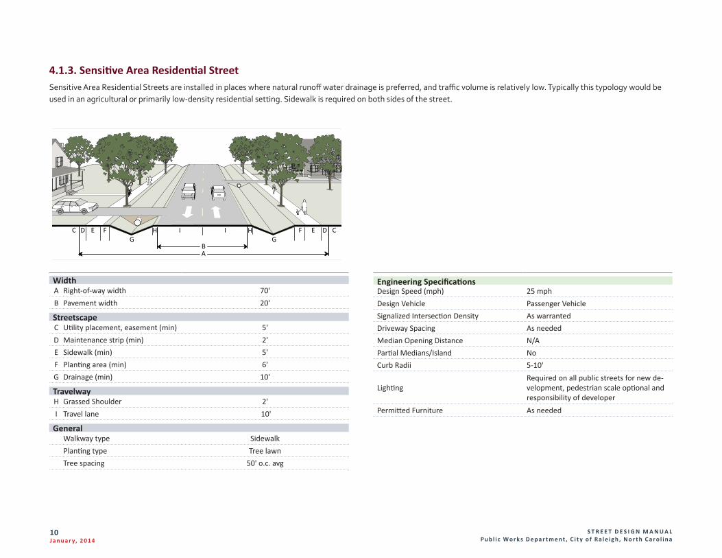
4.1.3. Sensitive Area Residential StreetSensitive Area Residential Streets are installed in places where natural runoff water drainage is preferred, and traffic volume is relatively low. Typically this typology would be used in an agricultural or primarily low-density residential setting. Sidewalk is required on both sides of the street.
Engineering SpecificationsDesign Speed (mph) 25 mphDesign Vehicle Passenger VehicleSignalized Intersection Density As warrantedDriveway Spacing As neededMedian Opening Distance N/APartial Medians/Island NoCurb Radii 5-10'
LightingRequired on all public streets for new de-velopment, pedestrian scale optional and responsibility of developer
Permitted Furniture As needed
WidthA Right-of-way width 70'B Pavement width 20'
StreetscapeC Utility placement, easement (min) 5'D Maintenance strip (min) 2'E Sidewalk (min) 5'F Planting area (min) 6'G Drainage (min) 10'
TravelwayH Grassed Shoulder 2'I Travel lane 10'
General Walkway type SidewalkPlanting type Tree lawnTree spacing 50' o.c. avg
EC I IH HG
FDG
AB
EF D C
S T R E E T D E S I G N M A N U A L Pu b l i c Wo r k s D e p a r t m e n t , C i t y o f R a l e i g h , N o r t h C a r o l i n a
11J a n u a r y, 2 014
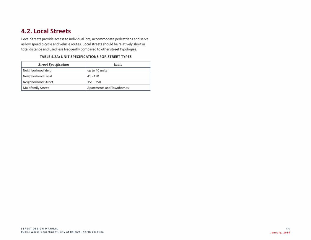
4.2. Local StreetsLocal Streets provide access to individual lots, accommodate pedestrians and serve as low speed bicycle and vehicle routes. Local streets should be relatively short in total distance and used less frequently compared to other street typologies.
TABLE 4.2A: UNIT SPECIFICATIONS FOR STREET TYPES
Street Specification Units
Neighborhood Yield up to 40 units
Neighborhood Local 41 - 150
Neighborhood Street 151 - 350
Multifamily Street Apartments and Townhomes
S T R E E T D E S I G N M A N U A L Pu b l i c Wo r k s D e p a r t m e n t , C i t y o f R a l e i g h , N o r t h C a r o l i n a
12J a n u a r y, 2 014
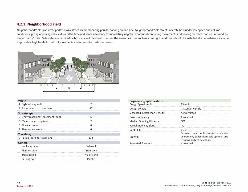
4.2.1. Neighborhood YieldNeighborhood Yield is an unstriped two-way street accommodating parallel parking on one side. Neighborhood Yield streets operate best under low speed and volume conditions, giving opposing vehicle drivers the time and space necessary to successfully negotiate potential conflicting movements and serving no more than 40 units and no longer than ½ mile. Sidewalks are required on both sides of the street. Items in the amenities zone such as streetlights and trees should be installed at a pedestrian scale so as to provide a high level of comfort for residents and non-motorized street users.
Engineering SpecificationsDesign Speed (mph) 25 mphDesign Vehicle Passenger VehicleSignalized Intersection Density As warrantedDriveway Spacing As neededMedian Opening Distance N/APartial Medians/Island NoCurb Radii 5-10'
LightingRequired on all public streets for new de-velopment, pedestrian scale optional and responsibility of developer
Permitted Furniture As needed
ED F G GBA
F E CDC
WidthA Right-of-way width 55'B Back-of-curb to back-of-curb 27'
StreetscapeC Utility placement, easement (min) 5'D Maintenance strip (min) 2'E Sidewalk (min) 6'F Planting area (min) 6'
TravelwayG Parallel parking/travel lane 13.5'
General Walkway type SidewalkPlanting type Tree lawnTree spacing 40' o.c. avgParking type Parallel
S T R E E T D E S I G N M A N U A L Pu b l i c Wo r k s D e p a r t m e n t , C i t y o f R a l e i g h , N o r t h C a r o l i n a
13J a n u a r y, 2 014
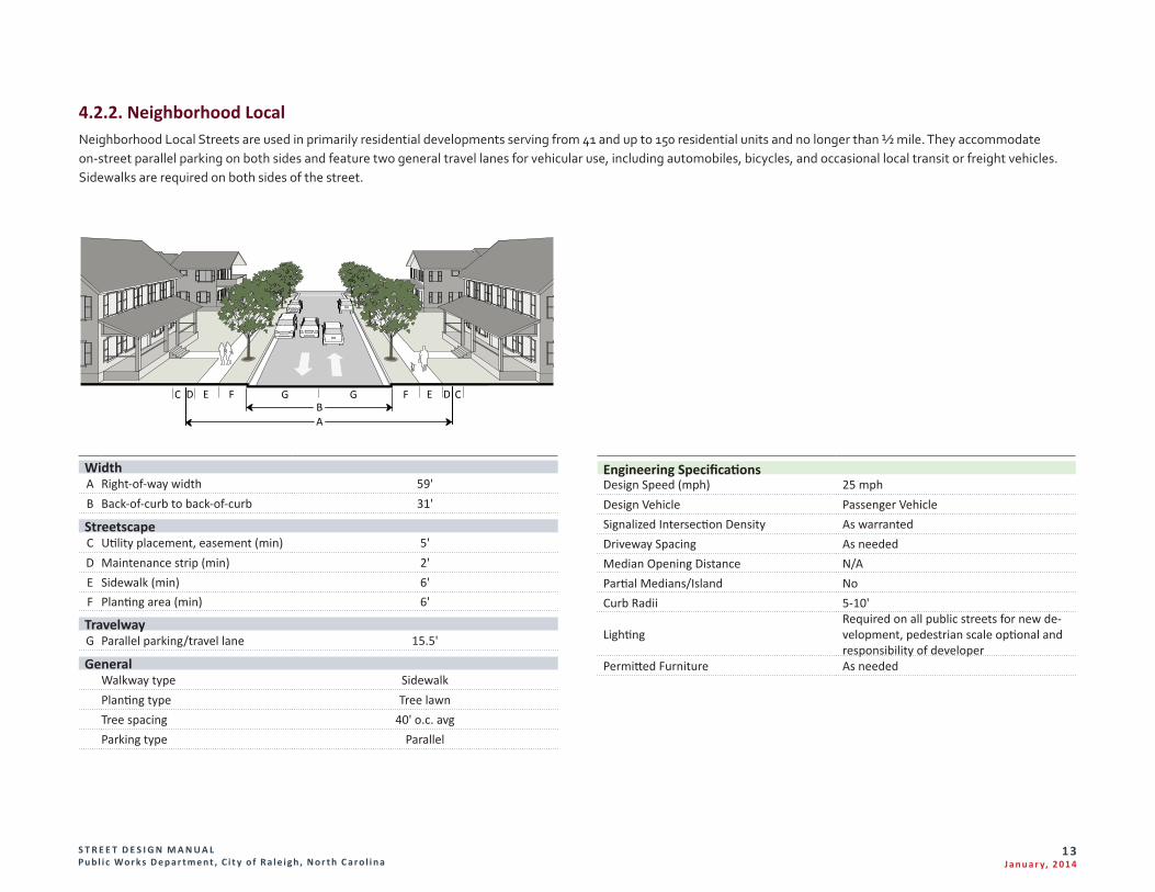
4.2.2. Neighborhood LocalNeighborhood Local Streets are used in primarily residential developments serving from 41 and up to 150 residential units and no longer than ½ mile. They accommodate on-street parallel parking on both sides and feature two general travel lanes for vehicular use, including automobiles, bicycles, and occasional local transit or freight vehicles. Sidewalks are required on both sides of the street.
Engineering SpecificationsDesign Speed (mph) 25 mphDesign Vehicle Passenger VehicleSignalized Intersection Density As warrantedDriveway Spacing As neededMedian Opening Distance N/APartial Medians/Island NoCurb Radii 5-10'
LightingRequired on all public streets for new de-velopment, pedestrian scale optional and responsibility of developer
Permitted Furniture As needed
WidthA Right-of-way width 59'B Back-of-curb to back-of-curb 31'
StreetscapeC Utility placement, easement (min) 5'D Maintenance strip (min) 2'E Sidewalk (min) 6'F Planting area (min) 6'
TravelwayG Parallel parking/travel lane 15.5'
General Walkway type SidewalkPlanting type Tree lawnTree spacing 40' o.c. avgParking type Parallel
ED F GBA
G F E DC C
S T R E E T D E S I G N M A N U A L Pu b l i c Wo r k s D e p a r t m e n t , C i t y o f R a l e i g h , N o r t h C a r o l i n a
14J a n u a r y, 2 014
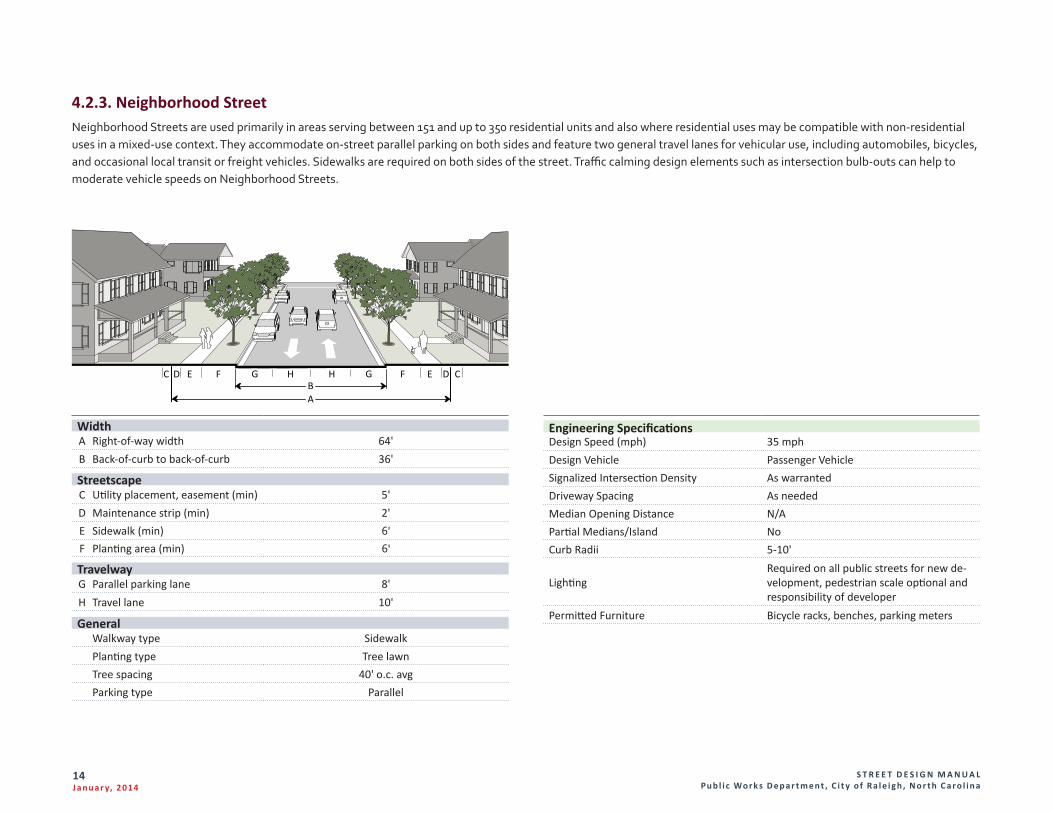
4.2.3. Neighborhood StreetNeighborhood Streets are used primarily in areas serving between 151 and up to 350 residential units and also where residential uses may be compatible with non-residential uses in a mixed-use context. They accommodate on-street parallel parking on both sides and feature two general travel lanes for vehicular use, including automobiles, bicycles, and occasional local transit or freight vehicles. Sidewalks are required on both sides of the street. Traffic calming design elements such as intersection bulb-outs can help to moderate vehicle speeds on Neighborhood Streets.
Engineering SpecificationsDesign Speed (mph) 35 mphDesign Vehicle Passenger VehicleSignalized Intersection Density As warrantedDriveway Spacing As neededMedian Opening Distance N/APartial Medians/Island NoCurb Radii 5-10'
LightingRequired on all public streets for new de-velopment, pedestrian scale optional and responsibility of developer
Permitted Furniture Bicycle racks, benches, parking meters
WidthA Right-of-way width 64'B Back-of-curb to back-of-curb 36'
StreetscapeC Utility placement, easement (min) 5'D Maintenance strip (min) 2'E Sidewalk (min) 6'F Planting area (min) 6'
TravelwayG Parallel parking lane 8'H Travel lane 10'
General Walkway type SidewalkPlanting type Tree lawnTree spacing 40' o.c. avgParking type Parallel
ED F G HHBA
G F E DC C
S T R E E T D E S I G N M A N U A L Pu b l i c Wo r k s D e p a r t m e n t , C i t y o f R a l e i g h , N o r t h C a r o l i n a
15J a n u a r y, 2 014
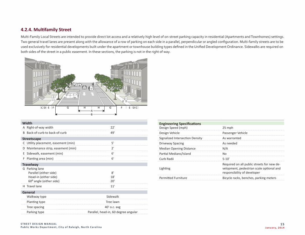
4.2.4. Multifamily StreetMulti-Family Local Streets are intended to provide direct lot access and a relatively high level of on-street parking capacity in residential (Apartments and Townhomes) settings. Two general travel lanes are present along with the allowance of a row of parking on each side in a parallel, perpendicular or angled configuration. Multi-family streets are to be used exclusively for residential developments built under the apartment or townhouse building types defined in the Unified Development Ordinance. Sidewalks are required on both sides of the street in a public easement. In these sections, the parking is not in the right of way.
Engineering SpecificationsDesign Speed (mph) 25 mphDesign Vehicle Passenger VehicleSignalized Intersection Density As warrantedDriveway Spacing As neededMedian Opening Distance N/APartial Medians/Island NoCurb Radii 5-10'
LightingRequired on all public streets for new de-velopment, pedestrian scale optional and responsibility of developer
Permitted Furniture Bicycle racks, benches, parking meters
F GE EHH
BA
G FDC CD
WidthA Right-of-way width 22'B Back-of-curb to back-of-curb 49'
Streetscape C Utility placement, easement (min) 5'D Maintenance strip, easement (min) 2'E Sidewalk, easement (min) 6'F Planting area (min) 6'
TravelwayG Parking lane
Parallel (either side) Head-in (either side) 60⁰ angle (either side)
8'18'20’
H Travel lane 11'
General Walkway type SidewalkPlanting type Tree lawnTree spacing 40' o.c. avgParking type Parallel, head-in, 60 degree angular
S T R E E T D E S I G N M A N U A L Pu b l i c Wo r k s D e p a r t m e n t , C i t y o f R a l e i g h , N o r t h C a r o l i n a
16J a n u a r y, 2 014
4.3. Mixed Use StreetsTwo general street typologies are listed under “Mixed Use Streets”: Avenues and Main Streets.
A. Avenues are walkable, low-speed streets, generally shorter in length than boulevards. They provide access to abutting commercial and mixed land uses as well as multi-unit residential development. They serve as primary bicycle and pedestrian routes, and may accommodate local transit vehicles. Avenues may feature a median and on-street parking.
B. Main Streets are designed to provide connections between neighborhoods and districts, as well as providing access to Avenues and Boulevards from local streets. Main Streets are highly walkable and may serve as the primary street for commercial or mixed-use centers. On-street parking is typically provided.
S T R E E T D E S I G N M A N U A L Pu b l i c Wo r k s D e p a r t m e n t , C i t y o f R a l e i g h , N o r t h C a r o l i n a
17J a n u a r y, 2 014
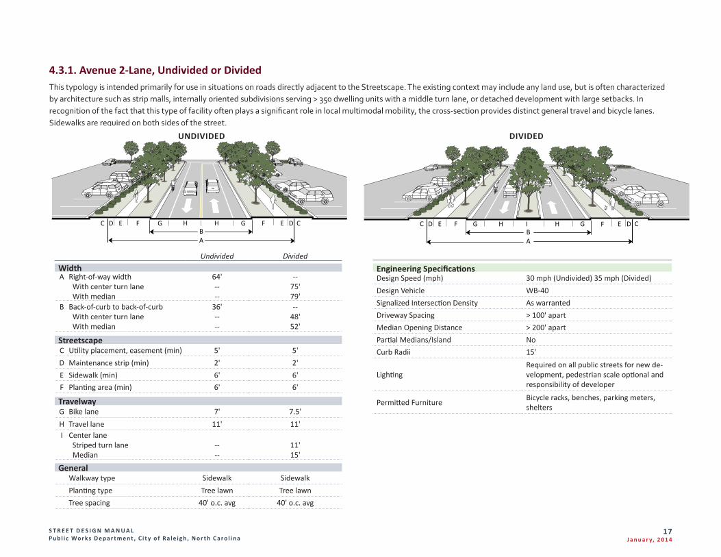
4.3.1. Avenue 2-Lane, Undivided or DividedThis typology is intended primarily for use in situations on roads directly adjacent to the Streetscape. The existing context may include any land use, but is often characterized by architecture such as strip malls, internally oriented subdivisions serving > 350 dwelling units with a middle turn lane, or detached development with large setbacks. In recognition of the fact that this type of facility often plays a significant role in local multimodal mobility, the cross-section provides distinct general travel and bicycle lanes. Sidewalks are required on both sides of the street.
Undivided DividedWidthA Right-of-way width
With center turn lane With median
64'----
--75'79'
B Back-of-curb to back-of-curb With center turn lane With median
36'----
--48'52'
StreetscapeC Utility placement, easement (min) 5' 5'D Maintenance strip (min) 2' 2'E Sidewalk (min) 6' 6'F Planting area (min) 6' 6'
TravelwayG Bike lane 7' 7.5'H Travel lane 11' 11'I Center lane
Striped turn lane Median
----
11'15'
General Walkway type Sidewalk Sidewalk Planting type Tree lawn Tree lawnTree spacing 40' o.c. avg 40' o.c. avg
E F G HBA
G F EDC CDH
Engineering SpecificationsDesign Speed (mph) 30 mph (Undivided) 35 mph (Divided)Design Vehicle WB-40Signalized Intersection Density As warrantedDriveway Spacing > 100' apartMedian Opening Distance > 200' apartPartial Medians/Island NoCurb Radii 15'
LightingRequired on all public streets for new de-velopment, pedestrian scale optional and responsibility of developer
Permitted Furniture Bicycle racks, benches, parking meters, shelters
E F G H HIBA
G F E CDC D
UNDIVIDED DIVIDED
S T R E E T D E S I G N M A N U A L Pu b l i c Wo r k s D e p a r t m e n t , C i t y o f R a l e i g h , N o r t h C a r o l i n a
18J a n u a r y, 2 014
C D FE EG H GBA
F D C
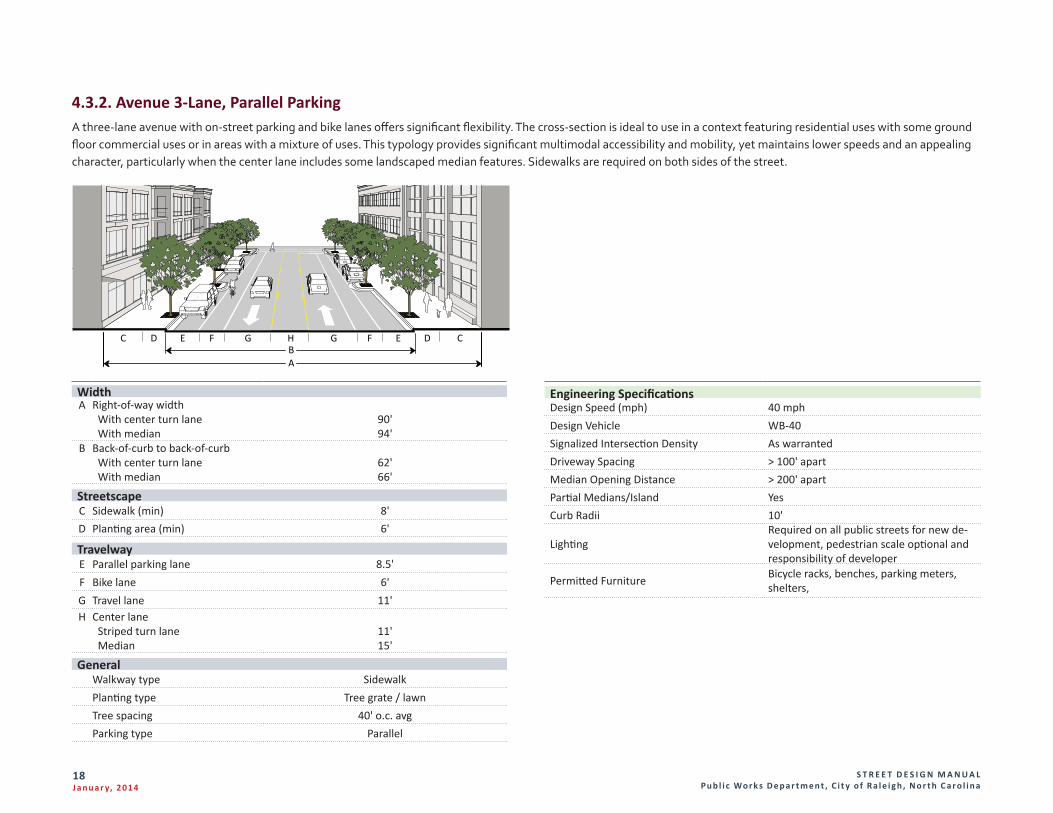
4.3.2. Avenue 3-Lane, Parallel ParkingA three-lane avenue with on-street parking and bike lanes offers significant flexibility. The cross-section is ideal to use in a context featuring residential uses with some ground floor commercial uses or in areas with a mixture of uses. This typology provides significant multimodal accessibility and mobility, yet maintains lower speeds and an appealing character, particularly when the center lane includes some landscaped median features. Sidewalks are required on both sides of the street.
WidthA Right-of-way width
With center turn lane With median
90'94'
B Back-of-curb to back-of-curb With center turn lane With median
62'66'
StreetscapeC Sidewalk (min) 8'D Planting area (min) 6'
TravelwayE Parallel parking lane 8.5'F Bike lane 6'G Travel lane 11'H Center lane
Striped turn lane Median
11'15'
General Walkway type Sidewalk Planting type Tree grate / lawnTree spacing 40' o.c. avgParking type Parallel
Engineering SpecificationsDesign Speed (mph) 40 mphDesign Vehicle WB-40Signalized Intersection Density As warrantedDriveway Spacing > 100' apartMedian Opening Distance > 200' apartPartial Medians/Island YesCurb Radii 10'
LightingRequired on all public streets for new de-velopment, pedestrian scale optional and responsibility of developer
Permitted Furniture Bicycle racks, benches, parking meters, shelters,
S T R E E T D E S I G N M A N U A L Pu b l i c Wo r k s D e p a r t m e n t , C i t y o f R a l e i g h , N o r t h C a r o l i n a
19J a n u a r y, 2 014
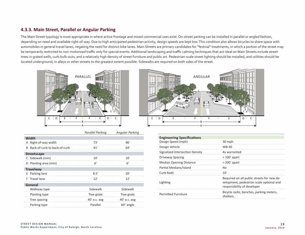
4.3.3. Main Street, Parallel or Angular ParkingThe Main Street typology is most appropriate in where active frontage and mixed commercial uses exist. On-street parking can be installed in parallel or angled fashion, depending on need and available right-of-way. Due to high anticipated pedestrian activity, design speeds are kept low. This condition also allows bicycles to share space with automobiles in general travel lanes, negating the need for distinct bike lanes. Main Streets are primary candidates for “festival” treatments, in which a portion of the street may be temporarily restricted to non-motorized traffic only for special events. Additional landscaping and traffic calming techniques that are ideal on Main Streets include street trees in grated wells, curb bulb-outs, and a relatively high density of street furniture and public art. Pedestrian-scale street lighting should be installed, and utilities should be located underground, in alleys or other streets to the greatest extent possible. Sidewalks are required on both sides of the street.
Engineering SpecificationsDesign Speed (mph) 30 mphDesign Vehicle WB-40Signalized Intersection Density As warrantedDriveway Spacing > 100' apartMedian Opening Distance > 200' apartPartial Medians/Island NoCurb Radii 10'
LightingRequired on all public streets for new de-velopment, pedestrian scale optional and responsibility of developer
Permitted Furniture Bicycle racks, benches, parking meters, shelters,
Parallel Parking Angular Parking
WidthA Right-of-way width 73' 96'B Back-of-curb to back-of-curb 41' 64'
StreetscapeC Sidewalk (min) 10' 10'D Planting area (min) 6' 6'
TravelwayE Parking lane 8.5' 20'F Travel lane 12' 12'
General Walkway type Sidewalk Sidewalk Planting type Tree grate Tree grateTree spacing 40' o.c. avg 40' o.c. avgParking type Parallel 60° angle
C D E F FBA
E D C C D E FFBA
E D C
PARALLEL ANGULAR
S T R E E T D E S I G N M A N U A L Pu b l i c Wo r k s D e p a r t m e n t , C i t y o f R a l e i g h , N o r t h C a r o l i n a
20J a n u a r y, 2 014
4.4. Major StreetsA. The categories of streets classified as “Major Streets” are Avenues with four or
more lanes and Boulevards.
1. Four and Six Lane Avenues have a similar purpose to two- and three-lane Avenues but apply to thoroughfare and arterial streets that require four or more lanes to accommodate traffic demand. Avenues with four or more lanes always feature medians. Signalized intersections are spaced further apart on major streets to better facilitate vehicular mobility. Midblock pedestrian crossings shall be installed on long blocks to maintain walkability in areas where pedestrian usage could be heavy. Major transit routes are often found on these corridors.
2. Boulevards are designed to support multiple travel modes, including automobiles, freight movers, transit vehicles, pedestrians and bicyclists. Boulevards balance high vehicular capacity with high pedestrian and vehicular accessibility to adjoining urban land uses. Landscaped medians separate and buffer through traffic from a local access are that accommodate parking, low-speed vehicular traffic, bicyclists and pedestrians.
B. There are two typical multi-way boulevard configurations: parallel and angled parking where a center median exists with two additional side medians and accessway. Multi-Way configurations are intended to fully support multiple travel modes, providing a high level of mobility and access. They have high vehicular capacity and side accessways provide additional options for right turns, allowing intersections to operate more efficiently.
S T R E E T D E S I G N M A N U A L Pu b l i c Wo r k s D e p a r t m e n t , C i t y o f R a l e i g h , N o r t h C a r o l i n a
21J a n u a r y, 2 014
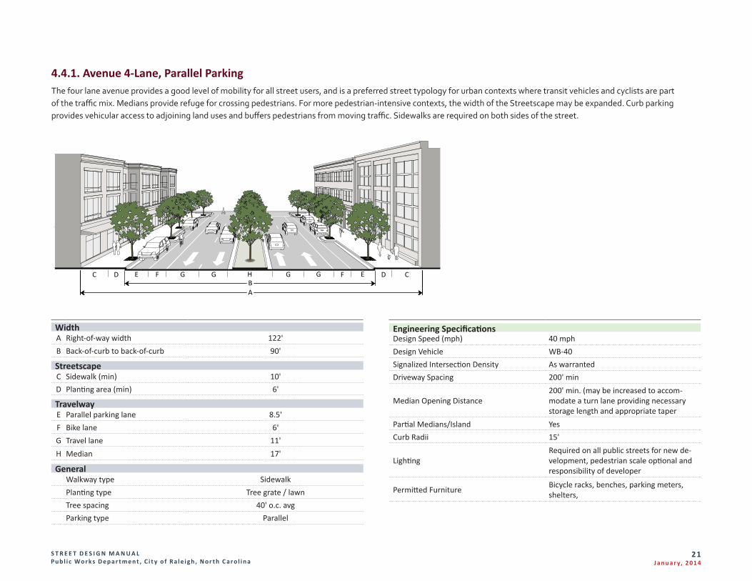
4.4.1. Avenue 4-Lane, Parallel ParkingThe four lane avenue provides a good level of mobility for all street users, and is a preferred street typology for urban contexts where transit vehicles and cyclists are part of the traffic mix. Medians provide refuge for crossing pedestrians. For more pedestrian-intensive contexts, the width of the Streetscape may be expanded. Curb parking provides vehicular access to adjoining land uses and buffers pedestrians from moving traffic. Sidewalks are required on both sides of the street.
Engineering SpecificationsDesign Speed (mph) 40 mphDesign Vehicle WB-40Signalized Intersection Density As warrantedDriveway Spacing 200' min
Median Opening Distance200' min. (may be increased to accom-modate a turn lane providing necessary storage length and appropriate taper
Partial Medians/Island YesCurb Radii 15'
LightingRequired on all public streets for new de-velopment, pedestrian scale optional and responsibility of developer
Permitted Furniture Bicycle racks, benches, parking meters, shelters,
WidthA Right-of-way width 122'B Back-of-curb to back-of-curb 90'
StreetscapeC Sidewalk (min) 10'D Planting area (min) 6'
TravelwayE Parallel parking lane 8.5'F Bike lane 6'G Travel lane 11'H Median 17'
General Walkway type Sidewalk Planting type Tree grate / lawnTree spacing 40' o.c. avgParking type Parallel
C D FE EGG H G GBA
F D C
S T R E E T D E S I G N M A N U A L Pu b l i c Wo r k s D e p a r t m e n t , C i t y o f R a l e i g h , N o r t h C a r o l i n a
22J a n u a r y, 2 014
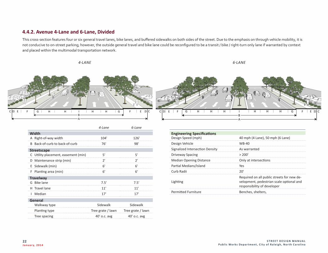
4.4.2. Avenue 4-Lane and 6-Lane, DividedThis cross-section features four or six general travel lanes, bike lanes, and buffered sidewalks on both sides of the street. Due to the emphasis on through vehicle mobility, it is not conducive to on-street parking; however, the outside general travel and bike lane could be reconfigured to be a transit / bike / right-turn only lane if warranted by context and placed within the multimodal transportation network.
Engineering SpecificationsDesign Speed (mph) 40 mph (4 Lane), 50 mph (6 Lane)Design Vehicle WB-40Signalized Intersection Density As warrantedDriveway Spacing > 200'Median Opening Distance Only at intersectionsPartial Medians/Island YesCurb Radii 20'
LightingRequired on all public streets for new de-velopment, pedestrian scale optional and responsibility of developer
Permitted Furniture Benches, shelters,
E F G H HH I HH HBA
G F EC D CDE F G HHBA
C D EFGH HI CD
4-Lane 6-Lane
WidthA Right-of-way width 104' 126'B Back-of-curb to back-of-curb 76' 98'
StreetscapeC Utility placement, easement (min) 5' 5'D Maintenance strip (min) 2' 2'E Sidewalk (min) 6' 6'F Planting area (min) 6' 6'
TravelwayG Bike lane 7.5' 7.5'H Travel lane 11' 11'I Median 17' 17'
General Walkway type Sidewalk SidewalkPlanting type Tree grate / lawn Tree grate / lawnTree spacing 40' o.c. avg 40' o.c. avg
4-LANE 6-LANE
S T R E E T D E S I G N M A N U A L Pu b l i c Wo r k s D e p a r t m e n t , C i t y o f R a l e i g h , N o r t h C a r o l i n a
23J a n u a r y, 2 014
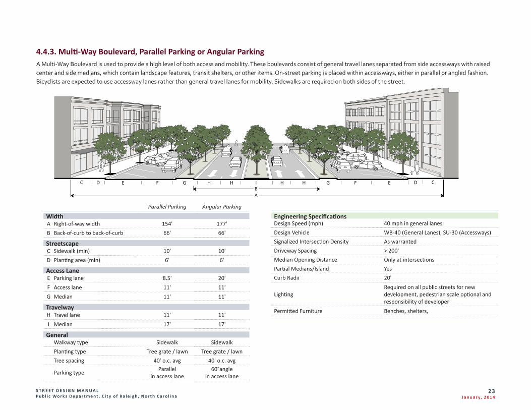
4.4.3. Multi-Way Boulevard, Parallel Parking or Angular ParkingA Multi-Way Boulevard is used to provide a high level of both access and mobility. These boulevards consist of general travel lanes separated from side accessways with raised center and side medians, which contain landscape features, transit shelters, or other items. On-street parking is placed within accessways, either in parallel or angled fashion. Bicyclists are expected to use accessway lanes rather than general travel lanes for mobility. Sidewalks are required on both sides of the street.
Engineering SpecificationsDesign Speed (mph) 40 mph in general lanesDesign Vehicle WB-40 (General Lanes), SU-30 (Accessways)Signalized Intersection Density As warrantedDriveway Spacing > 200'Median Opening Distance Only at intersectionsPartial Medians/Island YesCurb Radii 20'
LightingRequired on all public streets for new development, pedestrian scale optional and responsibility of developer
Permitted Furniture Benches, shelters,
Parallel Parking Angular Parking
WidthA Right-of-way width 154' 177'B Back-of-curb to back-of-curb 66' 66'
StreetscapeC Sidewalk (min) 10' 10'D Planting area (min) 6' 6'
Access LaneE Parking lane 8.5' 20'F Access lane 11' 11'G Median 11' 11'
TravelwayH Travel lane 11' 11'I Median 17' 17'
General Walkway type Sidewalk Sidewalk Planting type Tree grate / lawn Tree grate / lawnTree spacing 40' o.c. avg 40' o.c. avg
Parking type Parallel in access lane
60°angle in access lane
C D D CE F G IH HBA
G F EH H
S T R E E T D E S I G N M A N U A L Pu b l i c Wo r k s D e p a r t m e n t , C i t y o f R a l e i g h , N o r t h C a r o l i n a
24J a n u a r y, 2 014
4.5. Industrial and Service StreetsA. Streets within industrial and service areas typically carry lower traffic volumes
but accommodate a higher proportion of truck traffic. Pedestrian facilities do not need to be as generous as in mixed-use areas, and separate bicycle facilities are not provided for. This street section represents the minimum standard for commercial property for the purpose of facility fees and reimbursements.
B. A related typology is the alley, defined as a narrow low-speed road behind buildings that provides access to parking, service areas and rear uses such as accessory structures. It may also accommodate utilities, in shoulders or easements. Some informal pedestrian and bicycle use is to be expected on alleys, but these activities can share space with motorized vehicles due to land constraints, general lack of amenities, and low traffic volume. Sidewalks are required on both sides of the street.
S T R E E T D E S I G N M A N U A L Pu b l i c Wo r k s D e p a r t m e n t , C i t y o f R a l e i g h , N o r t h C a r o l i n a
25J a n u a r y, 2 014
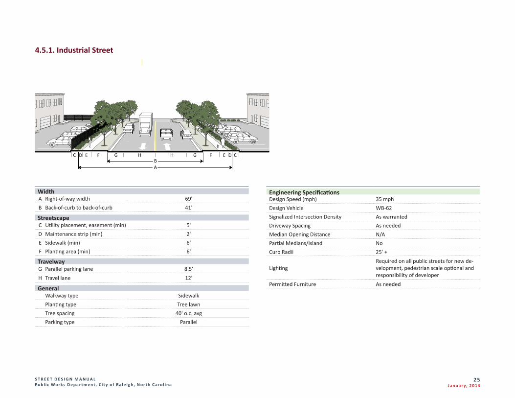
4.5.1. Industrial Street
Engineering SpecificationsDesign Speed (mph) 35 mphDesign Vehicle WB-62Signalized Intersection Density As warrantedDriveway Spacing As neededMedian Opening Distance N/APartial Medians/Island NoCurb Radii 25' +
LightingRequired on all public streets for new de-velopment, pedestrian scale optional and responsibility of developer
Permitted Furniture As needed
WidthA Right-of-way width 69'B Back-of-curb to back-of-curb 41'
StreetscapeC Utility placement, easement (min) 5'D Maintenance strip (min) 2'E Sidewalk (min) 6'F Planting area (min) 6'
TravelwayG Parallel parking lane 8.5'H Travel lane 12'
General Walkway type Sidewalk Planting type Tree lawnTree spacing 40' o.c. avgParking type Parallel
E F HHG GBA
F EDC CD
S T R E E T D E S I G N M A N U A L Pu b l i c Wo r k s D e p a r t m e n t , C i t y o f R a l e i g h , N o r t h C a r o l i n a
26J a n u a r y, 2 014
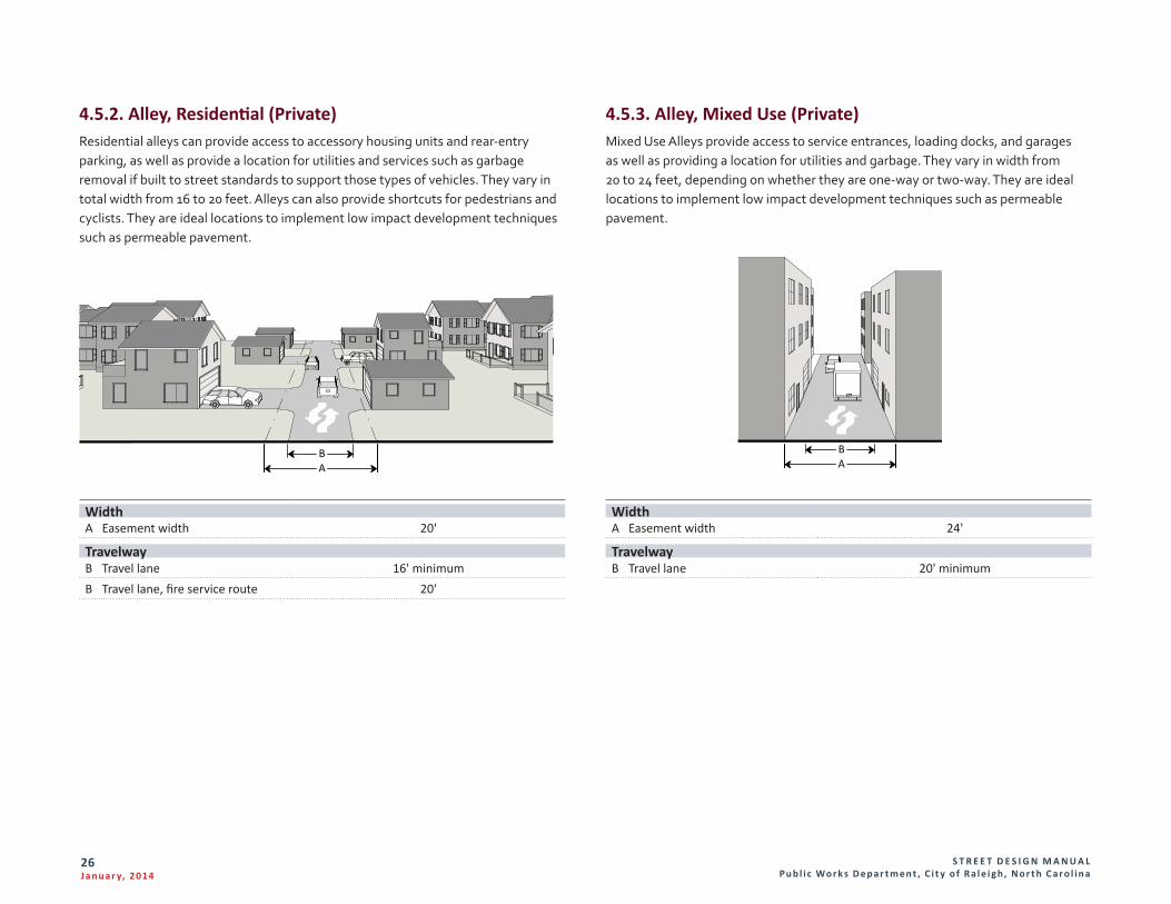
4.5.2. Alley, Residential (Private)Residential alleys can provide access to accessory housing units and rear-entry parking, as well as provide a location for utilities and services such as garbage removal if built to street standards to support those types of vehicles. They vary in total width from 16 to 20 feet. Alleys can also provide shortcuts for pedestrians and cyclists. They are ideal locations to implement low impact development techniques such as permeable pavement.
4.5.3. Alley, Mixed Use (Private)Mixed Use Alleys provide access to service entrances, loading docks, and garages as well as providing a location for utilities and garbage. They vary in width from 20 to 24 feet, depending on whether they are one-way or two-way. They are ideal locations to implement low impact development techniques such as permeable pavement.
WidthA Easement width 20'
TravelwayB Travel lane 16' minimumB Travel lane, fire service route 20'
WidthA Easement width 24'
TravelwayB Travel lane 20' minimum
BA
BA
S T R E E T D E S I G N M A N U A L Pu b l i c Wo r k s D e p a r t m e n t , C i t y o f R a l e i g h , N o r t h C a r o l i n a
27J a n u a r y, 2 014
4.6. Private AccesswaysAccessways are used to provide a formal travel path within a block for pedestrians and/or vehicles.
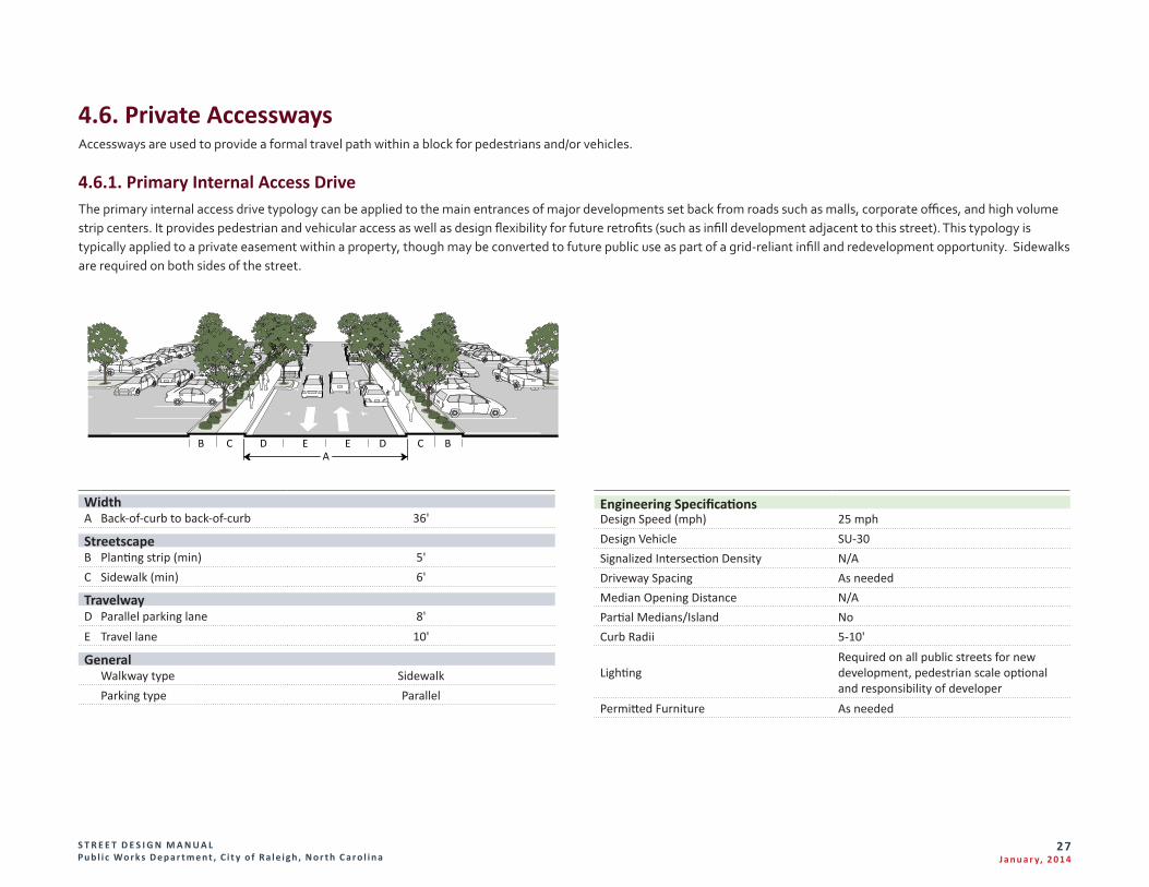
4.6.1. Primary Internal Access DriveThe primary internal access drive typology can be applied to the main entrances of major developments set back from roads such as malls, corporate offices, and high volume strip centers. It provides pedestrian and vehicular access as well as design flexibility for future retrofits (such as infill development adjacent to this street). This typology is typically applied to a private easement within a property, though may be converted to future public use as part of a grid-reliant infill and redevelopment opportunity. Sidewalks are required on both sides of the street.
Engineering SpecificationsDesign Speed (mph) 25 mphDesign Vehicle SU-30Signalized Intersection Density N/ADriveway Spacing As neededMedian Opening Distance N/APartial Medians/Island NoCurb Radii 5-10'
LightingRequired on all public streets for new development, pedestrian scale optional and responsibility of developer
Permitted Furniture As needed
B C D EEA
D C B
WidthA Back-of-curb to back-of-curb 36'
StreetscapeB Planting strip (min) 5'C Sidewalk (min) 6'
TravelwayD Parallel parking lane 8'E Travel lane 10'
General Walkway type Sidewalk Parking type Parallel
S T R E E T D E S I G N M A N U A L Pu b l i c Wo r k s D e p a r t m e n t , C i t y o f R a l e i g h , N o r t h C a r o l i n a
28J a n u a r y, 2 014
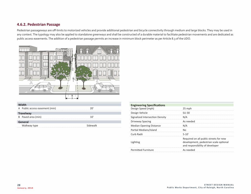
4.6.2. Pedestrian PassagePedestrian passageways are off-limits to motorized vehicles and provide additional pedestrian and bicycle connectivity through medium and large blocks. They may be used in any context. The typology may also be applied to standalone greenways and shall be constructed of a durable material to facilitate pedestrian movements and are dedicated as public access easements. The addition of a pedestrian passage permits an increase in minimum block perimeter as per Article 8.3 of the UDO.
Engineering SpecificationsDesign Speed (mph) 25 mphDesign Vehicle SU-30Signalized Intersection Density N/ADriveway Spacing As neededMedian Opening Distance N/APartial Medians/Island NoCurb Radii 5-10'
LightingRequired on all public streets for new development, pedestrian scale optional and responsibility of developer
Permitted Furniture As needed
WidthA Public access easement (min) 20'
TravelwayB Paved area (min) 10'
General Walkway type Sidewalk
BA
S T R E E T D E S I G N M A N U A L Pu b l i c Wo r k s D e p a r t m e n t , C i t y o f R a l e i g h , N o r t h C a r o l i n a
29J a n u a r y, 2 014
Section 5. Administrative Procedures and Policies5.1.2. New StreetsThe Public Works Director may in accordance with Sec. 10.2.18 approve a street design adjustment to the standards of Article 8.4, subject to all of the following findings:
A. The approved adjustment meets the intent of this Article.
B. The approved adjustment complies with the Comprehensive Plan and adopted City plans.
C. The approved adjustment does not increase congestion or compromise safety.
D. The approved adjustment does not create additional maintenance responsibilities for the City.
E. The approved adjustment has been designed and certified by a Professional engineer.
F. The approved adjustment shall address stormwater collection and conveyance and not adversely impact stormwater collection.
5.1.3. Existing StreetsThe Public Works Director may in accordance with Sec. 10.2.18 approve a design adjustment to the standards of Article 8.5, subject to all of the following findings:
A. Administrative Design Adjustment Findings:
1. The approved adjustment meets the intent of this Article.
2. The approved adjustment complies with the Comprehensive Plan and adopted City plans.
3. The approved adjustment does not increase congestion or compromise safety.
4. The approved adjustment does not create additional maintenance responsibilities for the City.
5. The approved adjustment has been designed and certified by a Professional engineer.
Many of these policies and procedures can be found in the Unified Development Ordinance (hereby UDO), of the City of Raleigh Code.
5.1. Administrative Design AdjustmentAdministrative Design Adjustment Findings may be found in Chapter 8 of the UDO. They may be applied to regulations in Article 8.3 for Blocks, Lots, Access, Article 8.4 for New Streets, and Article 8.5 for Existing Streets.
5.1.1. Blocks, Lots, AccessThe Public Works Director may in accordance with Sec. 10.2.18 approve a design adjustment to the standards of Article 8.3, subject to all of the following findings:
A. The approved design adjustment meets the intent of this Article.
B. The approved design adjustment complies with the Comprehensive Plan and adopted City plans.
C. The approved design adjustment does not increase congestion or compromise safety.
D. The approved adjustment does not create any lots without direct street frontage.
E. The design adjustment is deemed reasonable due to one or more of the following:
1. Topographic changes are too steep;
2. The presence of existing buildings, streams, other natural features;
3. Site layout of developed properties;
4. Adjoining uses or their vehicles are incompatible; or
5. Strict compliance would pose a safety hazard.
6. Does not conflict with an approved or built roadway construction project adjacent to or in the vicinity of the site.
F. No design adjustment shall be approved when the City Council has authorized a roadway project in the vicinity, where the roadway design has not yet been finalized.
S T R E E T D E S I G N M A N U A L Pu b l i c Wo r k s D e p a r t m e n t , C i t y o f R a l e i g h , N o r t h C a r o l i n a
30J a n u a r y, 2 014
5.2. Encroachments in the Right-of-WayThe Encroachment approval is a process by which private property owners, firms or corporations may request use of the Public Right of Way for private purposes, such as landscaping, structures or outdoor dining. This review process is intended to ensure the health and safety of the public, as well as protection against potential damage to the streetscape, trees and vegetation, sidewalks, streets, and other publicly owned amenities.
5.2.1. Major EncroachmentsMajor Encroachments are permanent structures for private use on public right-of-way in any part of the City. Examples include landscaping and cable and data transmission lines. City Council reviews and approves major encroachments following staff reviews.
5.2.2. Minor EncroachmentsMinor Encroachments are temporary items for private use on public right-of-way. Examples include outdoor dining tables, awnings and street vending carts. Minor encroachments are permitted in these areas: Downtown Overlay District, Glenwood South Business Districts, North Person Street Business District, Peace Street Business District and sections of Hillsborough Street. Requests for minor encroachments are reviewed and approved City staff.
5.3. Infrastructure Requirements5.3.1. Infrastructure Sufficiency A. To lessen congestion in the streets, and to facilitate the efficient and adequate
provision of transportation, water and sewage and to secure safety from fire, every subdivision plan and site plan shall be subject to a determination of the sufficiency of infrastructure, as defined below according to the established levels of service in this Article.
B. Infrastructure shall be considered sufficient where it is demonstrated to have available capacity to accommodate the demand generated by the proposed development as well as other approved developments and Planned Development Master Plans.
C. In order to avoid undue hardship, the applicant may propose to construct or secure sufficient funding for the facilities necessary to provide capacity to accommodate the proposed development at the adopted level of service. The commitment for construction or advancement of necessary facilities shall be included as a condition of development.
5.3.2. Roadway Construction Through and Adjoining Developments A. All public roadways inside the Corporate limits of the City shall be constructed in
conformance with City standards and specifications; however, if the roadway is maintained by NCDOT, then the roadway shall be constructed in conformance with either City or NCDOT standards and specifications, whichever is more stringent.
B. All public roadways that are outside the Corporate limits of the City and when water or sewer is connected to the City utility system or made available within one (1) year after approval of a development plan, shall be constructed in conformance with either City or NCDOT standards and specifications, whichever is more stringent.
C. Roadways that are outside the Corporate limits of the City and where neither City water nor sewer are available or made available within one (1) year after approval of a site plan, shall be constructed in conformance with NCDOT standards and specifications.
D. Roadways that are within a Watershed Protection Area Overlay District or classified as a sensitive area thoroughfare, shall be constructed in conformance with either City or NCDOT standards and specifications, whichever is more stringent.
E. The minimum design cross-section for roadways constructed to City standards are illustrated in the City of Raleigh Standard Details Manual. Consult NCDOT for minimum design cross-sections for roadways that require their approval.
5.3.3. Minimum Paving ConstructionA. The developer shall be responsible for the cost and installation of the applicable
width and pavement design requirements. Frontage improvements shall be installed for roadways in accordance with adopted City or State standards and specifications. The developer shall make off site street improvements constructed to minimum street pavement standards in accordance with this section.
S T R E E T D E S I G N M A N U A L Pu b l i c Wo r k s D e p a r t m e n t , C i t y o f R a l e i g h , N o r t h C a r o l i n a
31J a n u a r y, 2 014
B. Minimum street pavement standards shall be twenty feet (20 feet) from edge of pavement to edge of pavement for two way streets. The street width may be increased at the discretion of the City, if required to mitigate safety problems or expected increases in traffic congestion.
C. The developer shall also provide additional pavement surfaces for turning movements to serve the development where prescribed by a traffic impact analysis or as specified elsewhere in this chapter. Street improvements required in excess of minimum paving construction standards associated with a site plan may be eligible for reimbursements per Section 8.6.3 of the UDO. Additional pavement surfaces required to accommodate turning movements generated by the development are not eligible for reimbursement.
D. The City may elect to require payment of a fee-in-lieu of installation to the applicable minimum paving construction standards as outlined in this section. Methodology for requiring fee-in-lieu payments is specified in the City’s administrative regulation for “Fee-in-lieu of Determination and Administration.
E. An exemption from paving construction requirements shall not relieve the developer of a payment in-lieu of construction unless otherwise specified below.
5.3.4. Fee in LieuA. Where the Public Works Director determines that construction of public
improvements would not be feasible, a fee in lieu may be permitted. In this instance, right-of-way dedication and all necessary easements shall be dedicated to the city. Engineering drawings may be required to determine the extent of public improvements and easements.
B. The installation of the designated streetscape is part of the construction of public improvements and shall be subject to a fee in lieu when the street is not to be constructed. In the event the streetscape is not installed, the following fee shall apply based on each tree required or tree grate that is installed. Please refer to the development fee schedule.
5.3.5. Exemptions to Fee in Lieu and pavement constructionA. Streets with curb and gutter, other than thoroughfare or collector system
roadways, which were built pursuant to earlier City or State paving standards, do not have to be widened unless such widening is needed to alleviate safety problems or increased traffic congestion. Sidewalk construction, curb and gutter improvements, and right-of-way dedications required in this chapter shall not be exempted by this provision.
B. Developments will not be responsible for street and streetscape construction requirements along existing or planned roadways if any of the following conditions exist:
1. Exemptions for construction shall be provided for existing single-family lots, single-family subdivisions which have all lots fronting on existing streets, and multi-unit conversions of existing single-family homes, except when construction is needed to extend adjacent street and sidewalk facilities.
2. Exemptions for street construction and fee-in-lieu payment for curb and gutter and sidewalk shall be provided for frontage on roadways that are exempt from curb and gutter requirements, such as streets within a Watershed Protection Overlay District. Construction or fee-in-lieu payment for additional pavement widths to provide sufficient travel lane or shoulder widths per minimum City or State standards may still be required.
3. Exemptions for street construction shall be provided for frontage along future thoroughfares when construction as part of the development is not required in the plan approval process.
4. Exemptions for street construction and fee-in-lieu payment shall be provided for frontage along streets approved for construction funding by the State Transportation Improvement Program or other State funding programs, provided that the NCDOT Board of Transportation has authorized the project for public bid or for right-of-way acquisition. The City’s street improvement assessment policies may be applicable in these cases, as directed by the City Council.
5. Exemptions shall be provided for frontage along streets approved for construction funding in the City’s Capital Improvement Program, provided that the City Council has authorized the project for public bid or for right-of-way acquisition. The City’s normal street improvement assessment policies will be applicable in these cases, as directed by the City Council.
S T R E E T D E S I G N M A N U A L Pu b l i c Wo r k s D e p a r t m e n t , C i t y o f R a l e i g h , N o r t h C a r o l i n a
32J a n u a r y, 2 014
6. Exemptions for street construction and fee-in-lieu payment shall be provided for frontage along existing or planned future roadways having full control of access (i.e., no direct access from the property to the roadway is permitted;
7. Exemptions for construction shall be provided where the City for the same improvements, or on a property where assessments for same street improvements by the City were previously levied has received a previous fee-in-lieu payment. In certain cases, the City may elect to refund a previous fee-in-lieu payment if the Public Works Director determines that construction of frontage improvements would be more appropriate.
5.4. Infrastructure Construction PlansThe Infrastructure Construction Plans review process is for applicants who want to install public or private infrastructure improvements associated with a development project. City staff reviews the plans for compliance with the City Code and regulations related to stormwater, public utilities, transportation, fire, urban forestry, planning and zoning.
5.5. Infrastructure Reimbursements5.5.1. Improvements Eligible for Reimbursement A. For further information, see Section 8.6.3 A and B of the Unified Development
Ordinance.
B. The City will pay to the developer unit costs for development-related improvements over and above the unit costs for applicable streets.
C. The following installations are eligible for reimbursement:
1. Any street construction in excess of the minimum standard needed to serve the development.
2. Any right-of-way dedication in excess of the minimum standard needed to serve the development.
3. Right-of-way for controlled-access freeways.
D. Reimbursements are subject to availability of funds and eligibility for reimbursement through the City’s facility fee program and are paid based on the unit prices in the Raleigh City Code.
5.5.2. Expiration of ReimbursementA. For further information, see Section 8.6.4 of the Unified Development
Ordinance.
B. Any request for reimbursement for street, greenway or utility installation must be submitted to the City within two years of completion and acceptance by the city or state, whichever is applicable.
5.6. Construction SuretyConstruction Surety applies when all public infrastructure related improvements and installations are not completed and accepted by the City of Raleigh. The purpose of this surety is for the protection of the homeowners and businesses affected by the development, in case the developer does not complete the public improvements. This guarantees that the City will have the resources to complete the improvements. Construction Surety shall apply at the following stages:
A. If all development-related improvements and installations are not completed and accepted by the City prior to a request to record all or a part of any
S T R E E T D E S I G N M A N U A L Pu b l i c Wo r k s D e p a r t m e n t , C i t y o f R a l e i g h , N o r t h C a r o l i n a
33J a n u a r y, 2 014
subdivision or issuance of a building permit for any site plan, whichever first occurs, a security instrument shall be posted, in lieu of completion of the work, in an amount of 125% of the estimated construction cost of the development-related improvements which remain incomplete and with surety and conditions satisfactory to the City, providing for and securing to the City the actual construction and installation of improvements.
B. All development-related improvements that are secured by a surety shall be installed prior to the issuance of the first certificate of occupancy within the subdivision phase or prior to the issuance of the first certificate of occupancy for the site plan, whichever event first occurs on the property; however, the final coat of asphalt for street improvements and the installation of required street furniture or sidewalks (not required per the NC Building Code) may at the option of the applicant be installed within 24 months following the issuance of the first certificate of occupancy provided surety in the amount of 125% of these improvements are first provided to the City. Where improvements are required on a State-maintained road, a 100% construction surety is required. In this instance, proof of bond or surety with the State must be supplied to the City.
C. Where the Director of Public Works determines that landscaping in the public right-of-way cannot be installed due to inclement weather conditions, a surety in the amount of 125% of the value of the landscaping shall be provided to the City, in accordance with section 8.5.1.B. The landscaping improvements shall be installed within 12 months of issuance of the conditional letter of final acceptance.
5.7. NCDOT CoordinationA. Any time a project has the potential to impact a State maintained roadway, all
efforts should be made to coordinate with the North Carolina Department of Transportation (NCDOT). Therefore, a joint meeting between the applicant, NCDOT and the City is often recommended early in the process to discuss project details. Some details include, but not limited to, access location and types, potential roadway improvements, necessary Right of Way dedication and a project timeline.
B. Within the City of Raleigh’s jurisdiction, the City has site plan approval for developments; however on State maintained roadways the NCDOT has the ultimate authority for any work in the Right of Way. It is the sole responsibility of the requesting party to determine if a street is State maintained or not.
C. It is common for a project to involve both the NCDOT and the City of Raleigh. Plan submittals, review and approvals should be coordinated concurrently with both agencies to avoid conflicting requirements. In situations where an agency’s regulation differs from that of the other agency, the more restrictive of the two shall govern.
D. Applicant is encouraged to coordinate early and often with the two agencies, because NCDOT’s review process does not always coincide with the City’s, the Notification of any changes to a project’s plan based on review comments or requirements is essential to avoiding delays in the approval process.
E. The NCDOT’s Street and Driveway Access Permit Application requires a Local Governmental Authority’s approval prior to submission. The City must have an approved Site Plan prior to signing the back of NCDOT’s application form. Likewise, the City will withhold final Construction Drawings approval until all executed NCDOT permits are approved.
F. As a project moves forward into the construction phase, both the NCDOT and the City of Raleigh have enforcement authority to ensure safety in the Right of Way is not being compromised. Both agencies have the ability to affect a project’s progress if there is reason to believe proper construction practices are not being adhered to and/or if unsuitable materials are being used in the Right of Way. Failure to comply with permits and the approved plans may result in revocation of permits.
G. The City of Raleigh has the authority to withhold the issuance of a Certificate of Occupancy until all work is completed and in compliance with the approved permits.
H. For additional information regarding the coordination between NCDOT and the City of Raleigh please see NCDOT-Policy On Street And Driveway Access to North Carolina Highways, Chapter 2, section A.
5.8. Public Street Right-of-Way ConveyanceA. Proposed Public Right of Way shall be dedicated in accordance with the current
Street Typology Map and Slope Easements where applicable.
1. Freeways/expressways - the minimum right-of-way width required to serve a development. (To determine the minimum required right-of-way for streets by type and intensity, see definitions of roadways in the streets section).
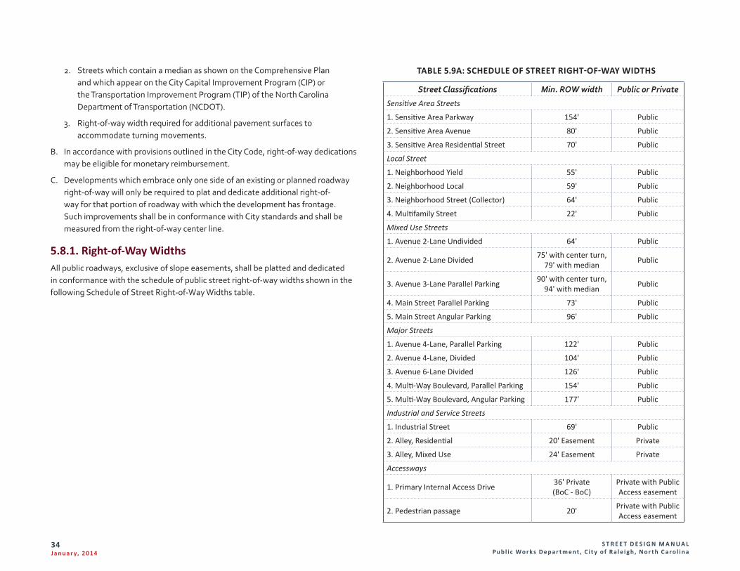
S T R E E T D E S I G N M A N U A L Pu b l i c Wo r k s D e p a r t m e n t , C i t y o f R a l e i g h , N o r t h C a r o l i n a
34J a n u a r y, 2 014
2. Streets which contain a median as shown on the Comprehensive Plan and which appear on the City Capital Improvement Program (CIP) or the Transportation Improvement Program (TIP) of the North Carolina Department of Transportation (NCDOT).
3. Right-of-way width required for additional pavement surfaces to accommodate turning movements.
B. In accordance with provisions outlined in the City Code, right-of-way dedications may be eligible for monetary reimbursement.
C. Developments which embrace only one side of an existing or planned roadway right-of-way will only be required to plat and dedicate additional right-of-way for that portion of roadway with which the development has frontage. Such improvements shall be in conformance with City standards and shall be measured from the right-of-way center line.
5.8.1. Right-of-Way WidthsAll public roadways, exclusive of slope easements, shall be platted and dedicated in conformance with the schedule of public street right-of-way widths shown in the following Schedule of Street Right-of-Way Widths table.
TABLE 5.9A: SCHEDULE OF STREET RIGHT-OF-WAY WIDTHS
Street Classifications Min. ROW width Public or Private
Sensitive Area Streets
1. Sensitive Area Parkway 154' Public
2. Sensitive Area Avenue 80' Public
3. Sensitive Area Residential Street 70' Public
Local Street
1. Neighborhood Yield 55' Public
2. Neighborhood Local 59' Public
3. Neighborhood Street (Collector) 64' Public
4. Multifamily Street 22' Public
Mixed Use Streets
1. Avenue 2-Lane Undivided 64' Public
2. Avenue 2-Lane Divided 75' with center turn, 79' with median Public
3. Avenue 3-Lane Parallel Parking 90' with center turn, 94' with median Public
4. Main Street Parallel Parking 73' Public
5. Main Street Angular Parking 96' Public
Major Streets
1. Avenue 4-Lane, Parallel Parking 122' Public
2. Avenue 4-Lane, Divided 104' Public
3. Avenue 6-Lane Divided 126' Public
4. Multi-Way Boulevard, Parallel Parking 154' Public
5. Multi-Way Boulevard, Angular Parking 177' Public
Industrial and Service Streets
1. Industrial Street 69' Public
2. Alley, Residential 20' Easement Private
3. Alley, Mixed Use 24' Easement Private
Accessways
1. Primary Internal Access Drive 36' Private (BoC - BoC)
Private with Public Access easement
2. Pedestrian passage 20' Private with Public Access easement
S T R E E T D E S I G N M A N U A L Pu b l i c Wo r k s D e p a r t m e n t , C i t y o f R a l e i g h , N o r t h C a r o l i n a
35J a n u a r y, 2 014
5.8.2. Coordination with Adopted Roadway PlansIt is the responsibility of the developer to take future roadway plans of the City and NCDOT into account when laying out a development plan.
5.8.3. Reservation Periods for Right-of-WayA. For thoroughfare system roadways where the planned right-of-way width
is greater than that which can be required, (as specified in the preceding paragraphs), the developer shall be required to reserve the extra right-of-way width for a period not to exceed 12 months from the date of approval of the development plan.
B. The reservation shall continue in effect for a period of not more than one year from the date of approval of the preliminary plan or site plan. This reservation period may be extended for an additional year upon submission of a letter to the City Council of intent to purchase by the appropriate governmental agency. Further extensions may be permitted upon mutual agreement between the land owner and the City Council, each of which shall not exceed two years.
5.8.4. Slope EasementsA. A slope easement of 20 feet in width shall be required adjoining each side of a
street right-of- way. The City may reduce or increase the slope easement width if due to terrain.
B. If a property owner submits to the City sufficient information to show that improvements to be located in the slope easement do not interfere with the right of the public to construct within the adjoining right-of-way, streets, sidewalks, or both, then the City shall allow the proposed improvement.
5.8.5. Adjustments to Required Right-of-Way WidthsThe Public Works Director may reduce the required minimum right-of-way width due to the location of an existing building or use in the proposed new right-of-way pursuant to section 5.1 of this Manual.
5.9. Temporary ROW Closure for Public Streets & SidewalksA. All sidewalk, traffic lane and on street parking closures must allow for safe
vehicular traffic flow and pedestrian access around the construction site. Sidewalk closures result in re-routing pedestrian traffic and must be reviewed for the safe movement of pedestrians and meet ADA (American Disability Act) requirements during construction.
B. Travel lanes and parking lanes must meet MUTCD standards.
C. Extra planning and design must be considered to provide for safe movement of vehicular and pedestrian traffic in areas where pedestrian activity is a priority such as where the DX district is mapped or where SF, UG or UL frontages are mapped.
D. Right of Way plan elements for temporary street/sidewalk closures associated with Commercial projects must include the following at a minimum:
1. location of the building on the site
2. location of the sidewalk
3. location of on-street parking
4. location of any transit facilities
5. direction of travel lanes
6. location of any streetscape item (utilities, street furniture, trees)
7. description of same improvements 100 feet to either side of the site
8. location of eight foot chain link fence
9. location of covered sidewalk and details of construction in accordance with the NC State Building Code, Chapter 33
10. site accessibility/ADA requirements in accordance with the NC Building Code and Section 8.3.5 of the UDO
11. location of barricades
12. location of traffic merge cones
13. location of businesses affected by barricades and/or fences
14. estimated timeframe for project
15. any items that will be affected by the closure
16. the logistics of the closure
S T R E E T D E S I G N M A N U A L Pu b l i c Wo r k s D e p a r t m e n t , C i t y o f R a l e i g h , N o r t h C a r o l i n a
36J a n u a r y, 2 014
5.10. Right-of-Way PermitsFor all permit issuance and fees, please see the Development Services – Customer Service Center and the current Development Fee Schedule.
5.10.1. Site FinalThe inspector will check the condition of the existing and new infrastructure improvements, and site related items.
5.10.2. Construction PurposesWhen work occurs in the public right of way such as lane closures, sidewalk closures and items not pertaining to street or sidewalk repair or improvements, this permit will be required.
5.10.3. Driveway/SidewalkWhen new curb cut construction is proposed, this permit will be required. When new sidewalk construction is proposed, not related to Infrastructure Construction Drawings, this permit will be required.
5.10.4. Street Cut permits (Permit to do work in the Public Right of Way)When existing sidewalk or a driveway is modified or replaced, this permit will be required. When utility contractors are doing work in the public right of way, this permit will be required.
5.10.5. Lane Closure PermitA permit required for the closure of a travel lane and/or parking lane measured from Back of Curb to Back of Curb. This permit is issued by the Public Works Department.
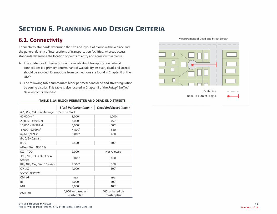
S T R E E T D E S I G N M A N U A L Pu b l i c Wo r k s D e p a r t m e n t , C i t y o f R a l e i g h , N o r t h C a r o l i n a
37J a n u a r y, 2 014
Section 6. Planning and Design Criteria
Dend-End Street Length
Centerline
Measurement of Dead-End Street Length6.1. ConnectivityConnectivity standards determine the size and layout of blocks within a place and the general density of intersections of transportation facilities, whereas access standards determine the location of points of entry and egress within blocks.
A. The existence of intersections and availability of transportation network connections is a primary determinant of walkability. As such, dead-end streets should be avoided. Exemptions from connections are found in Chapter 8 of the UDO.
B. The following table summarizes block perimeter and dead end street regulation by zoning district. This table is also located in Chapter 8 of the Raleigh Unified Development Ordinance.
TABLE 6.1A: BLOCK PERIMETER AND DEAD END STREETS
Block Perimeter (max.) Dead End Street (max.)R-1, R-2, R-4, R-6: Average Lot Size on Block40,000+ sf 8,000' 1,000'20,000 - 39,999 sf 6,000' 750'10,000 - 19,999 sf 5,000' 600' 6,000 - 9,999 sf 4,500' 550'up to 5,999 sf 3,000' 400'R-10: By DistrictR-10 2,500' 300'Mixed Used DistrictsDX-, -TOD 2,000' Not Allowed RX-, NX-, CX-, OX-: 3 or 4 Stories 3,000' 400'
RX-, NX-, CX-, OX-: 5 Stories 2,500' 300'OP-, IX-, 4,000' 500'Special DistrictsCM, AP n/a n/aIH 6,000' 400'MH 3,000' 400'
CMP, PD 4,000' or based on master plan
400' or based on master plan
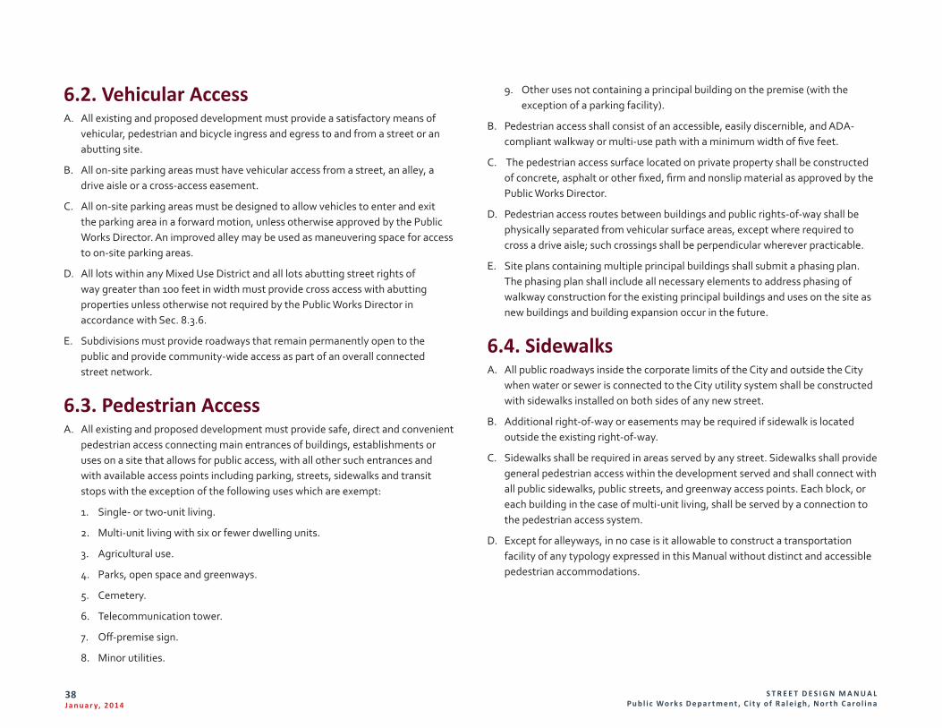
S T R E E T D E S I G N M A N U A L Pu b l i c Wo r k s D e p a r t m e n t , C i t y o f R a l e i g h , N o r t h C a r o l i n a
38J a n u a r y, 2 014
6.2. Vehicular AccessA. All existing and proposed development must provide a satisfactory means of
vehicular, pedestrian and bicycle ingress and egress to and from a street or an abutting site.
B. All on-site parking areas must have vehicular access from a street, an alley, a drive aisle or a cross-access easement.
C. All on-site parking areas must be designed to allow vehicles to enter and exit the parking area in a forward motion, unless otherwise approved by the Public Works Director. An improved alley may be used as maneuvering space for access to on-site parking areas.
D. All lots within any Mixed Use District and all lots abutting street rights of way greater than 100 feet in width must provide cross access with abutting properties unless otherwise not required by the Public Works Director in accordance with Sec. 8.3.6.
E. Subdivisions must provide roadways that remain permanently open to the public and provide community-wide access as part of an overall connected street network.
6.3. Pedestrian AccessA. All existing and proposed development must provide safe, direct and convenient
pedestrian access connecting main entrances of buildings, establishments or uses on a site that allows for public access, with all other such entrances and with available access points including parking, streets, sidewalks and transit stops with the exception of the following uses which are exempt:
1. Single- or two-unit living.
2. Multi-unit living with six or fewer dwelling units.
3. Agricultural use.
4. Parks, open space and greenways.
5. Cemetery.
6. Telecommunication tower.
7. Off-premise sign.
8. Minor utilities.
9. Other uses not containing a principal building on the premise (with the exception of a parking facility).
B. Pedestrian access shall consist of an accessible, easily discernible, and ADA-compliant walkway or multi-use path with a minimum width of five feet.
C. The pedestrian access surface located on private property shall be constructed of concrete, asphalt or other fixed, firm and nonslip material as approved by the Public Works Director.
D. Pedestrian access routes between buildings and public rights-of-way shall be physically separated from vehicular surface areas, except where required to cross a drive aisle; such crossings shall be perpendicular wherever practicable.
E. Site plans containing multiple principal buildings shall submit a phasing plan. The phasing plan shall include all necessary elements to address phasing of walkway construction for the existing principal buildings and uses on the site as new buildings and building expansion occur in the future.
6.4. Sidewalks A. All public roadways inside the corporate limits of the City and outside the City
when water or sewer is connected to the City utility system shall be constructed with sidewalks installed on both sides of any new street.
B. Additional right-of-way or easements may be required if sidewalk is located outside the existing right-of-way.
C. Sidewalks shall be required in areas served by any street. Sidewalks shall provide general pedestrian access within the development served and shall connect with all public sidewalks, public streets, and greenway access points. Each block, or each building in the case of multi-unit living, shall be served by a connection to the pedestrian access system.
D. Except for alleyways, in no case is it allowable to construct a transportation facility of any typology expressed in this Manual without distinct and accessible pedestrian accommodations.
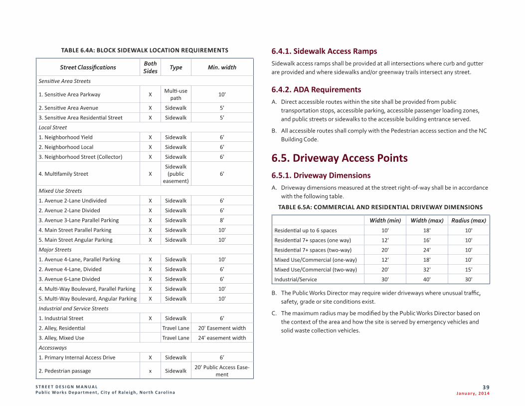
S T R E E T D E S I G N M A N U A L Pu b l i c Wo r k s D e p a r t m e n t , C i t y o f R a l e i g h , N o r t h C a r o l i n a
39J a n u a r y, 2 014
TABLE 6.4A: BLOCK SIDEWALK LOCATION REQUIREMENTS
Street Classifications Both Sides
Type Min. width
Sensitive Area Streets
1. Sensitive Area Parkway X Multi-use path 10'
2. Sensitive Area Avenue X Sidewalk 5'
3. Sensitive Area Residential Street X Sidewalk 5'
Local Street
1. Neighborhood Yield X Sidewalk 6'
2. Neighborhood Local X Sidewalk 6'
3. Neighborhood Street (Collector) X Sidewalk 6'
4. Multifamily Street XSidewalk (public
easement)6'
Mixed Use Streets
1. Avenue 2-Lane Undivided X Sidewalk 6'
2. Avenue 2-Lane Divided X Sidewalk 6'
3. Avenue 3-Lane Parallel Parking X Sidewalk 8'
4. Main Street Parallel Parking X Sidewalk 10'
5. Main Street Angular Parking X Sidewalk 10'
Major Streets
1. Avenue 4-Lane, Parallel Parking X Sidewalk 10'
2. Avenue 4-Lane, Divided X Sidewalk 6'
3. Avenue 6-Lane Divided X Sidewalk 6'
4. Multi-Way Boulevard, Parallel Parking X Sidewalk 10'
5. Multi-Way Boulevard, Angular Parking X Sidewalk 10'
Industrial and Service Streets
1. Industrial Street X Sidewalk 6'
2. Alley, Residential Travel Lane 20' Easement width
3. Alley, Mixed Use Travel Lane 24' easement width
Accessways
1. Primary Internal Access Drive X Sidewalk 6’
2. Pedestrian passage x Sidewalk 20' Public Access Ease-ment
6.4.1. Sidewalk Access RampsSidewalk access ramps shall be provided at all intersections where curb and gutter are provided and where sidewalks and/or greenway trails intersect any street.
6.4.2. ADA RequirementsA. Direct accessible routes within the site shall be provided from public
transportation stops, accessible parking, accessible passenger loading zones, and public streets or sidewalks to the accessible building entrance served.
B. All accessible routes shall comply with the Pedestrian access section and the NC Building Code.
6.5. Driveway Access Points 6.5.1. Driveway DimensionsA. Driveway dimensions measured at the street right-of-way shall be in accordance
with the following table.
TABLE 6.5A: COMMERCIAL AND RESIDENTIAL DRIVEWAY DIMENSIONS
Width (min) Width (max) Radius (max)
Residential up to 6 spaces 10' 18' 10'
Residential 7+ spaces (one way) 12' 16' 10'
Residential 7+ spaces (two-way) 20' 24' 10'
Mixed Use/Commercial (one-way) 12' 18' 10'
Mixed Use/Commercial (two-way) 20' 32' 15'
Industrial/Service 30' 40' 30'
B. The Public Works Director may require wider driveways where unusual traffic, safety, grade or site conditions exist.
C. The maximum radius may be modified by the Public Works Director based on the context of the area and how the site is served by emergency vehicles and solid waste collection vehicles.
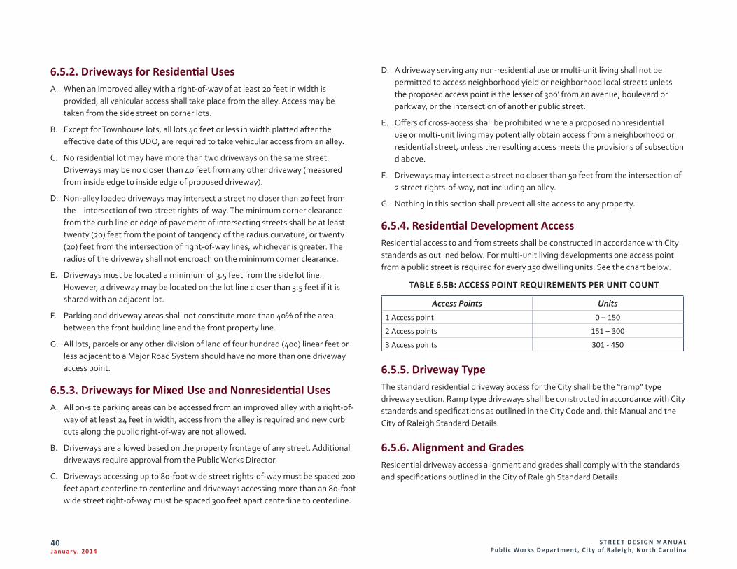
S T R E E T D E S I G N M A N U A L Pu b l i c Wo r k s D e p a r t m e n t , C i t y o f R a l e i g h , N o r t h C a r o l i n a
40J a n u a r y, 2 014
6.5.2. Driveways for Residential UsesA. When an improved alley with a right-of-way of at least 20 feet in width is
provided, all vehicular access shall take place from the alley. Access may be taken from the side street on corner lots.
B. Except for Townhouse lots, all lots 40 feet or less in width platted after the effective date of this UDO, are required to take vehicular access from an alley.
C. No residential lot may have more than two driveways on the same street. Driveways may be no closer than 40 feet from any other driveway (measured from inside edge to inside edge of proposed driveway).
D. Non-alley loaded driveways may intersect a street no closer than 20 feet from the intersection of two street rights-of-way. The minimum corner clearance from the curb line or edge of pavement of intersecting streets shall be at least twenty (20) feet from the point of tangency of the radius curvature, or twenty (20) feet from the intersection of right-of-way lines, whichever is greater. The radius of the driveway shall not encroach on the minimum corner clearance.
E. Driveways must be located a minimum of 3.5 feet from the side lot line. However, a driveway may be located on the lot line closer than 3.5 feet if it is shared with an adjacent lot.
F. Parking and driveway areas shall not constitute more than 40% of the area between the front building line and the front property line.
G. All lots, parcels or any other division of land of four hundred (400) linear feet or less adjacent to a Major Road System should have no more than one driveway access point.
6.5.3. Driveways for Mixed Use and Nonresidential UsesA. All on-site parking areas can be accessed from an improved alley with a right-of-
way of at least 24 feet in width, access from the alley is required and new curb cuts along the public right-of-way are not allowed.
B. Driveways are allowed based on the property frontage of any street. Additional driveways require approval from the Public Works Director.
C. Driveways accessing up to 80-foot wide street rights-of-way must be spaced 200 feet apart centerline to centerline and driveways accessing more than an 80-foot wide street right-of-way must be spaced 300 feet apart centerline to centerline.
D. A driveway serving any non-residential use or multi-unit living shall not be permitted to access neighborhood yield or neighborhood local streets unless the proposed access point is the lesser of 300' from an avenue, boulevard or parkway, or the intersection of another public street.
E. Offers of cross-access shall be prohibited where a proposed nonresidential use or multi-unit living may potentially obtain access from a neighborhood or residential street, unless the resulting access meets the provisions of subsection d above.
F. Driveways may intersect a street no closer than 50 feet from the intersection of 2 street rights-of-way, not including an alley.
G. Nothing in this section shall prevent all site access to any property.
6.5.4. Residential Development AccessResidential access to and from streets shall be constructed in accordance with City standards as outlined below. For multi-unit living developments one access point from a public street is required for every 150 dwelling units. See the chart below.
TABLE 6.5B: ACCESS POINT REQUIREMENTS PER UNIT COUNT
Access Points Units
1 Access point 0 – 150
2 Access points 151 – 300
3 Access points 301 - 450
6.5.5. Driveway TypeThe standard residential driveway access for the City shall be the “ramp” type driveway section. Ramp type driveways shall be constructed in accordance with City standards and specifications as outlined in the City Code and, this Manual and the City of Raleigh Standard Details.
6.5.6. Alignment and GradesResidential driveway access alignment and grades shall comply with the standards and specifications outlined in the City of Raleigh Standard Details.
S T R E E T D E S I G N M A N U A L Pu b l i c Wo r k s D e p a r t m e n t , C i t y o f R a l e i g h , N o r t h C a r o l i n a
41J a n u a r y, 2 014
6.5.7. Plot plan criteria for residential driveway approvalsA. Plans shall bear the Note: "ALL CONSTRUCTION SHALL BE PER CITY OF
RALEIGH AND/OR NCDOT STANDARDS AND SPECIFICATIONS."
B. Show the property lines and dimension the subject lot.
C. Show location of residential structure.
D. Show and dimension any existing curb and gutter, and existing sidewalk.
E. Show recorded sight distance triangles or sight easements across the property frontage.
F. Locate and dimension all existing and proposed driveways, and their radii. Residential driveways dimensions are required to be per table in section 6.5.1 and perpendicular to the street within the right-of-way.
G. The driveway must be a minimum 18 feet in length as measured from the right-of-way line to the face of the garage or structure.
H. Label street name and dimension street of right-of-way(s).
I. Non-alley loaded driveways may intersect a street no closer than 20 feet from the intersection of two street rights-of-way. The minimum corner clearance from the curb line or edge of pavement of intersecting streets shall be at least twenty (20) feet from the point of tangency of the radius curvature, or twenty (20) feet from the intersection of right-of-way lines, whichever is greater. The radius of the driveway shall not encroach on the minimum corner clearance.
J. Driveways must be located a minimum of 3.5 feet from the side lot line. However, a driveway may be located on the lot line closer than 3.5 feet if it is shared with an adjacent lot.
K. No residential lot may have more than two driveways on the same street. Driveways may be no closer than 40 feet from any other driveway (measured from inside edge to inside edge of proposed driveway).
6.5.8. Commercial Development AccessA. Commercial driveway access to and from streets shall be constructed in
accordance with the standards and specifications provided in the manual, “Policy on Street and Driveway Access to North Carolina Highways,” as adopted and amended by NCDOT. The standard commercial driveway access for the City shall be the “street” type driveway section. Street type driveways shall be
constructed in accordance with City standards and specifications as outlined in the City Code, this Manual and the City of Raleigh Standard Details.
B. For any development, the number of driveway access points may be restricted where it is necessary for purposes of decreasing traffic congestion or hazards. These restrictions may include required common access points. Any required cross access documents shall be recorded by map and easement document prior to any permit issuance.
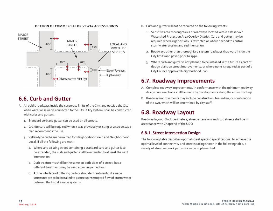
S T R E E T D E S I G N M A N U A L Pu b l i c Wo r k s D e p a r t m e n t , C i t y o f R a l e i g h , N o r t h C a r o l i n a
42J a n u a r y, 2 014
Edge of PavementRight-of-way
Driveway Access Point (typ.)
300’
300’
300’ 200’
100’
150’
LOCATION OF COMMERCIAL DRIVEWAY ACCESS POINTS
6.6. Curb and GutterA. All public roadways inside the corporate limits of the City, and outside the City
when water or sewer is connected to the City utility system, shall be constructed with curbs and gutters.
1. Standard curb and gutter can be used on all streets.
2. Granite curb will be required when it was previously existing or a streetscape plan recommends the use.
3. Valley-type curbs are permitted for Neighborhood Yield and Neighborhood Local, if all the following are met:
a. Where any existing street containing a standard curb and gutter is to be extended, the curb and gutter shall be extended to at least the next intersection.
b. Curb treatments shall be the same on both sides of a street, but a different treatment may be used adjoining a median.
c. At the interface of differing curb or shoulder treatments, drainage structures are to be installed to assure uninterrupted flow of storm water between the two drainage systems.
B. Curb and gutter will not be required on the following streets:
1. Sensitive area thoroughfares or roadways located within a Reservoir Watershed Protection Area Overlay District. Curb and gutter may be required where right-of-way is restricted or where needed to control stormwater erosion and sedimentation.
2. Roadways other than thoroughfare system roadways that were inside the City limits and paved prior to 1950.
3. Where curb and gutter is not planned to be installed in the future as part of design plans on street improvements, or where none is required as part of a City Council approved Neighborhood Plan.
6.7. Roadway ImprovementsA. Complete roadway improvements, in conformance with the minimum roadway
design cross-sections shall be made by developments along the entire frontage.
B. Roadway improvements may include construction, fee-in-lieu, or combination of the two, which will be determined by city staff.
6.8. Roadway LayoutRoadway layout, Block perimeters, street extensions and stub streets shall be in accordance with Chapter 8 of the UDO
6.8.1. Street Intersection DesignThe following table describes optimal street spacing specifications. To achieve the optimal level of connectivity and street spacing shown in the following table, a variety of street network patterns can be implemented.
MAJOR STREET
MAJOR STREET LOCAL AND
MIXED USE STREETS
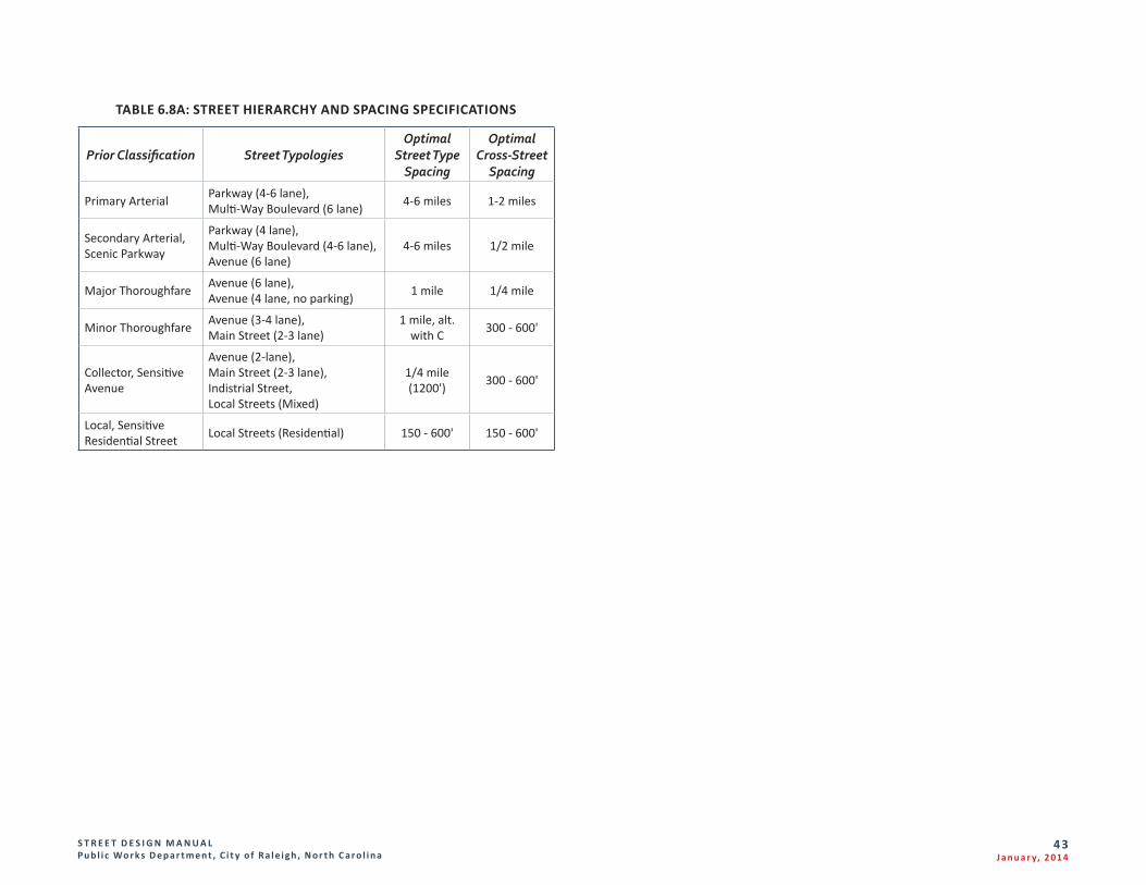
S T R E E T D E S I G N M A N U A L Pu b l i c Wo r k s D e p a r t m e n t , C i t y o f R a l e i g h , N o r t h C a r o l i n a
4 3J a n u a r y, 2 014
TABLE 6.8A: STREET HIERARCHY AND SPACING SPECIFICATIONS
Prior Classification Street TypologiesOptimal
Street Type Spacing
Optimal Cross-Street
Spacing
Primary Arterial Parkway (4-6 lane),Multi-Way Boulevard (6 lane) 4-6 miles 1-2 miles
Secondary Arterial, Scenic Parkway
Parkway (4 lane),Multi-Way Boulevard (4-6 lane),Avenue (6 lane)
4-6 miles 1/2 mile
Major Thoroughfare Avenue (6 lane),Avenue (4 lane, no parking) 1 mile 1/4 mile
Minor Thoroughfare Avenue (3-4 lane),Main Street (2-3 lane)
1 mile, alt. with C 300 - 600'
Collector, Sensitive Avenue
Avenue (2-lane),Main Street (2-3 lane),Indistrial Street,Local Streets (Mixed)
1/4 mile (1200') 300 - 600'
Local, Sensitive Residential Street Local Streets (Residential) 150 - 600' 150 - 600'
S T R E E T D E S I G N M A N U A L Pu b l i c Wo r k s D e p a r t m e n t , C i t y o f R a l e i g h , N o r t h C a r o l i n a
44J a n u a r y, 2 014
6.9. Cul-de-sac Design A. Minimum dimensions for circular cul-de-sac streets are shown in the City of Raleigh
Standard Details. Alternative turnaround designs on residential streets serving six dwelling units or less may be considered for alternate designs. Alternative designs must readily accommodate emergency vehicles and sanitation trucks.
B. Medians may be permitted where the cul-de-sac radius is increased and it can be demonstrated that emergency vehicles and sanitation trucks can be accommodated. The City will not maintain landscaped medians and a private maintenance agreement for the median shall be required to be approved by the City Attorney.
6.10. Horizontal Street DesignA. Design criteria for design speed, centerline radius, reverse curve tangent distance
and maximum superelevation rates for streets are summarized in Table 6.11A. Superelevation rates, minimum runoff lengths and methods of distribution should be in accordance with AASHTO standards and specifications.
B. The minimum tangent length of an approaching intersection should be 50 feet for local access system streets. All higher system streets shall have a tangent section no less than 100 feet approaching the intersection. Tangent lengths shall be measured from the intersection of the two rights-of-way.
6.11. Vertical Street DesignA. Wherever practical, streets should follow the existing contours of a site so as to
avoid excessive grading and removal of existing vegetation. Street grades shall not be less than 0.75%. Standards for vertical street design are listed in Table 6.11A.
B. At signalized intersections, the maximum grade approaching the intersection should not exceed two percent and extend a minimum distance of 200 feet in each direction measured from the outside edge of travel way of the intersecting street. For intersections not controlled by a traffic signal, the maximum grade approaching the intersection should not exceed five percent and extend a minimum distance of 100 feet in each direction.
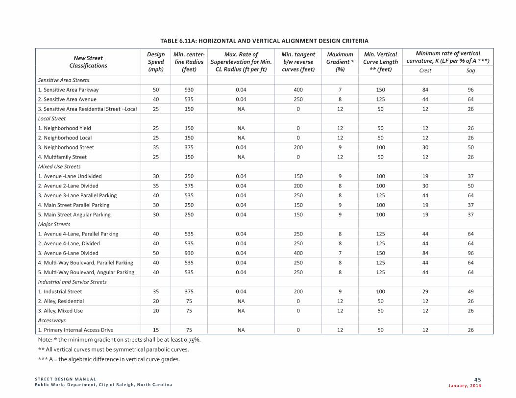
S T R E E T D E S I G N M A N U A L Pu b l i c Wo r k s D e p a r t m e n t , C i t y o f R a l e i g h , N o r t h C a r o l i n a
45J a n u a r y, 2 014
TABLE 6.11A: HORIZONTAL AND VERTICAL ALIGNMENT DESIGN CRITERIA
New Street Classifications
Design Speed (mph)
Min. center-line Radius
(feet)
Max. Rate of Superelevation for Min.
CL Radius (ft per ft)
Min. tangent b/w reverse
curves (feet)
Maximum Gradient *
(%)
Min. Vertical Curve Length
** (feet)
Minimum rate of vertical curvature, K (LF per % of A ***)
Crest Sag
Sensitive Area Streets
1. Sensitive Area Parkway 50 930 0.04 400 7 150 84 96
2. Sensitive Area Avenue 40 535 0.04 250 8 125 44 64
3. Sensitive Area Residential Street ¬Local 25 150 NA 0 12 50 12 26
Local Street
1. Neighborhood Yield 25 150 NA 0 12 50 12 26
2. Neighborhood Local 25 150 NA 0 12 50 12 26
3. Neighborhood Street 35 375 0.04 200 9 100 30 50
4. Multifamily Street 25 150 NA 0 12 50 12 26
Mixed Use Streets
1. Avenue -Lane Undivided 30 250 0.04 150 9 100 19 37
2. Avenue 2-Lane Divided 35 375 0.04 200 8 100 30 50
3. Avenue 3-Lane Parallel Parking 40 535 0.04 250 8 125 44 64
4. Main Street Parallel Parking 30 250 0.04 150 9 100 19 37
5. Main Street Angular Parking 30 250 0.04 150 9 100 19 37
Major Streets
1. Avenue 4-Lane, Parallel Parking 40 535 0.04 250 8 125 44 64
2. Avenue 4-Lane, Divided 40 535 0.04 250 8 125 44 64
3. Avenue 6-Lane Divided 50 930 0.04 400 7 150 84 96
4. Multi-Way Boulevard, Parallel Parking 40 535 0.04 250 8 125 44 64
5. Multi-Way Boulevard, Angular Parking 40 535 0.04 250 8 125 44 64
Industrial and Service Streets
1. Industrial Street 35 375 0.04 200 9 100 29 49
2. Alley, Residential 20 75 NA 0 12 50 12 26
3. Alley, Mixed Use 20 75 NA 0 12 50 12 26
Accessways
1. Primary Internal Access Drive 15 75 NA 0 12 50 12 26
Note: * the minimum gradient on streets shall be at least 0.75%.
** All vertical curves must be symmetrical parabolic curves.
*** A = the algebraic difference in vertical curve grades.
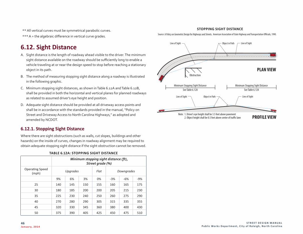
S T R E E T D E S I G N M A N U A L Pu b l i c Wo r k s D e p a r t m e n t , C i t y o f R a l e i g h , N o r t h C a r o l i n a
46J a n u a r y, 2 014
** All vertical curves must be symmetrical parabolic curves.
*** A = the algebraic difference in vertical curve grades.
6.12. Sight DistanceA. Sight distance is the length of roadway ahead visible to the driver. The minimum
sight distance available on the roadway should be sufficiently long to enable a vehicle traveling at or near the design speed to stop before reaching a stationary object in its path.
B. The method of measuring stopping sight distance along a roadway is illustrated in the following graphic.
C. Minimum stopping sight distances, as shown in Table 6.12A and Table 6.12B, shall be provided in both the horizontal and vertical planes for planned roadways as related to assumed driver’s eye height and position.
D. Adequate sight distance should be provided at all driveway access points and shall be in accordance with the standards provided in the manual, “Policy on Street and Driveway Access to North Carolina Highways,” as adopted and amended by NCDOT.
6.12.1. Stopping Sight DistanceWhere there are sight obstructions (such as walls, cut slopes, buildings and other hazards) on the inside of curves, changes in roadway alignment may be required to obtain adequate stopping sight distance if the sight obstruction cannot be removed.
TABLE 6.12A: STOPPING SIGHT DISTANCE Minimum stopping sight distance (ft),
Street grade (%)
Operating Speed (mph) Upgrades Flat Downgrades
9% 6% 3% 0% -3% -6% -9%
25 140 145 150 155 160 165 175
30 180 185 200 200 205 215 230
35 225 230 240 250 260 275 290
40 270 280 290 305 315 335 355
45 320 330 345 360 380 400 430
50 375 390 405 425 450 475 510
Line of SightObject in Path
Object in Path Line of SightLine of Sight
Line of Sight
Obstruction
Minimum Stopping Sight DistanceSee Table 6.12A
Minimum Stopping Sight DistanceSee Table 6.12A
Note: 1. Driver’s eye height shall be 3.5 feet above pavement 2. Object height shall be 0.5 feet above center of tra�c lane
PLAN VIEW
PROFILE VIEW
Source: A Policy on Geometric Design for Highways and Streets. American Association of State Highway and Transportation O�cials, 1990.
STOPPING SIGHT DISTANCE
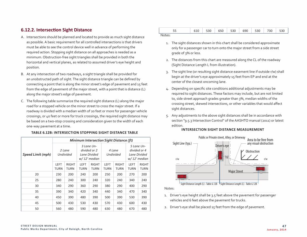
S T R E E T D E S I G N M A N U A L Pu b l i c Wo r k s D e p a r t m e n t , C i t y o f R a l e i g h , N o r t h C a r o l i n a
47J a n u a r y, 2 014
6.12.2. Intersection Sight DistanceA. Intersections should be planned and located to provide as much sight distance
as possible. A basic requirement for all controlled intersections is that drivers must be able to see the control device well in advance of performing the required action. Stopping sight distance on all approaches is needed as a minimum. Obstruction-free sight triangles shall be provided in both the horizontal and vertical planes, as related to assumed driver’s eye height and position.
B. At any intersection of two roadways, a sight triangle shall be provided for an unobstructed path of sight. The sight distance triangle can be defined by connecting a point that is along the minor street’s edge of pavement and 15 feet from the edge of pavement of the major street, with a point that is distance (L) along the major street’s edge of pavement.
C. The following table summarize the required sight distance (L) along the major road for a stopped vehicle on the minor street to cross the major street. If a roadway is divided with a median width of 20 feet or more for passenger vehicle crossings, or 40 feet or more for truck crossings, the required sight distance may be based on a two-stop crossing and consideration given to the width of each one-way pavement at a time.
TABLE 6.12B: INTERSECTION STOPPING SIGHT DISTANCE TABLE
Speed Limit (mph)
Minimum Intersection Sight Distance (ft)
2 Lane Undivided
3 Lane Un-divided or 2 Lane Divided
w/ 12' median
4 Lane Undivided
5 Lane Un-divided or 4 Lane Divided
w/ 12' median
LEFT TURN
RIGHT TURN
LEFT TURN
RIGHT TURN
LEFT TURN
RIGHT TURN
LEFT TURN
RIGHT TURN
20 230 200 240 200 250 200 270 200
25 280 240 300 240 320 240 340 240
30 340 290 360 290 380 290 400 290
35 390 340 420 340 440 340 470 340
40 450 390 480 390 500 390 530 390
45 500 430 530 430 570 430 600 430
50 560 480 590 480 630 480 670 480
55 610 530 650 530 690 530 730 530Notes:
1. The sight distances shown in this chart shall be considered approximate only for a passenger car to turn onto the major street from a side street grade of 3% or less.
2. The distances from this chart are measured along the CL of the roadway (Sight Distance Length L from illustration).
3. The sight line (or resulting sight distance easement line if outside r/w) shall begin at the driver's eye approximately 15 feet from EP and end at the center of the closest oncoming lane.
4. Depending on specific site conditions additional adjustments may be required to sight distances. These factors may include, but are not limited to, side street approach grades greater than 3%, median widths of the crossing street, skewed intersections, or other variables that would affect sight distances.
5. Any adjustments to the above sight distances shall be in accordance with section "9.5.3 Intersection Control" of the AASHTO manual (2011) or latest edition.
Obstruction
Area to be free fromSight Line (typ.)
Street or drive way
15’
Major Street
Sight Distance Length (L) - Table 6.12BSight Distance Length (L) - Table 6.12B
Driver’s eye
r/w r/w
any visual obstruction
INTERSECTION SIGHT DISTANCE MEASUREMENT
Notes:
1. Driver’s eye height shall be 3.5 feet above the pavement for passenger vehicles and 6 feet above the pavement for trucks.
2. Driver’s eye shall be placed 15 feet from the edge of pavement.
Public or Private street, Alley, or Driveway
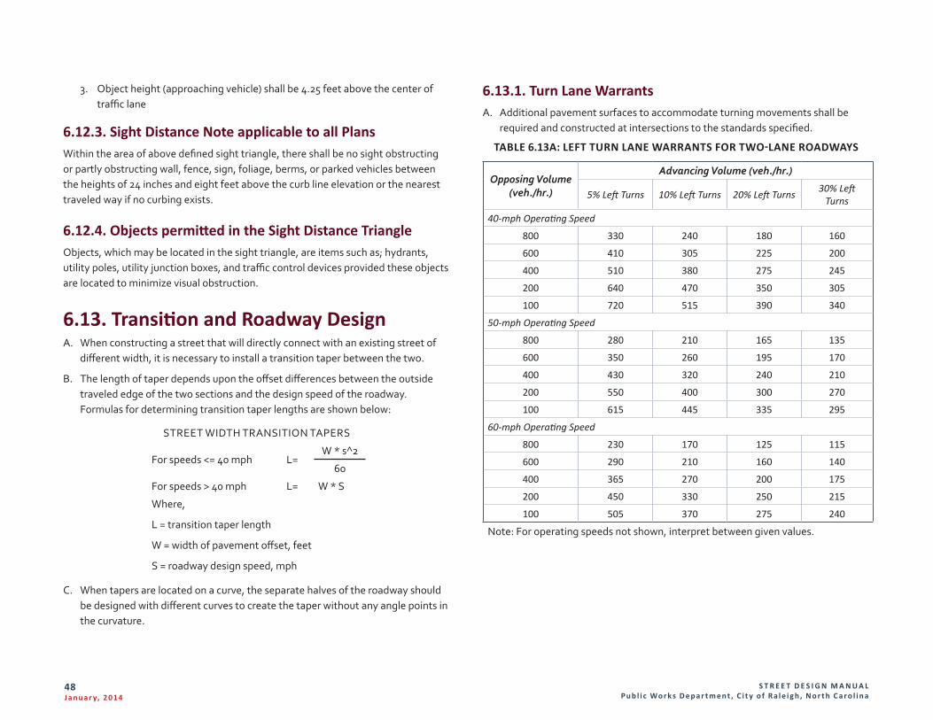
S T R E E T D E S I G N M A N U A L Pu b l i c Wo r k s D e p a r t m e n t , C i t y o f R a l e i g h , N o r t h C a r o l i n a
48J a n u a r y, 2 014
3. Object height (approaching vehicle) shall be 4.25 feet above the center of traffic lane
6.12.3. Sight Distance Note applicable to all PlansWithin the area of above defined sight triangle, there shall be no sight obstructing or partly obstructing wall, fence, sign, foliage, berms, or parked vehicles between the heights of 24 inches and eight feet above the curb line elevation or the nearest traveled way if no curbing exists.
6.12.4. Objects permitted in the Sight Distance TriangleObjects, which may be located in the sight triangle, are items such as; hydrants, utility poles, utility junction boxes, and traffic control devices provided these objects are located to minimize visual obstruction.
6.13. Transition and Roadway DesignA. When constructing a street that will directly connect with an existing street of
different width, it is necessary to install a transition taper between the two.
B. The length of taper depends upon the offset differences between the outside traveled edge of the two sections and the design speed of the roadway. Formulas for determining transition taper lengths are shown below:
STREET WIDTH TRANSITION TAPERS
For speeds <= 40 mph L=W * s^2
60
For speeds > 40 mph L= W * S
Where,
L = transition taper length
W = width of pavement offset, feet
S = roadway design speed, mph
C. When tapers are located on a curve, the separate halves of the roadway should be designed with different curves to create the taper without any angle points in the curvature.
6.13.1. Turn Lane WarrantsA. Additional pavement surfaces to accommodate turning movements shall be
required and constructed at intersections to the standards specified.
TABLE 6.13A: LEFT TURN LANE WARRANTS FOR TWO-LANE ROADWAYS
Opposing Volume (veh./hr.)
Advancing Volume (veh./hr.)
5% Left Turns 10% Left Turns 20% Left Turns 30% Left Turns
40-mph Operating Speed
800 330 240 180 160
600 410 305 225 200
400 510 380 275 245
200 640 470 350 305
100 720 515 390 340
50-mph Operating Speed
800 280 210 165 135
600 350 260 195 170
400 430 320 240 210
200 550 400 300 270
100 615 445 335 295
60-mph Operating Speed
800 230 170 125 115
600 290 210 160 140
400 365 270 200 175
200 450 330 250 215
100 505 370 275 240
Note: For operating speeds not shown, interpret between given values.
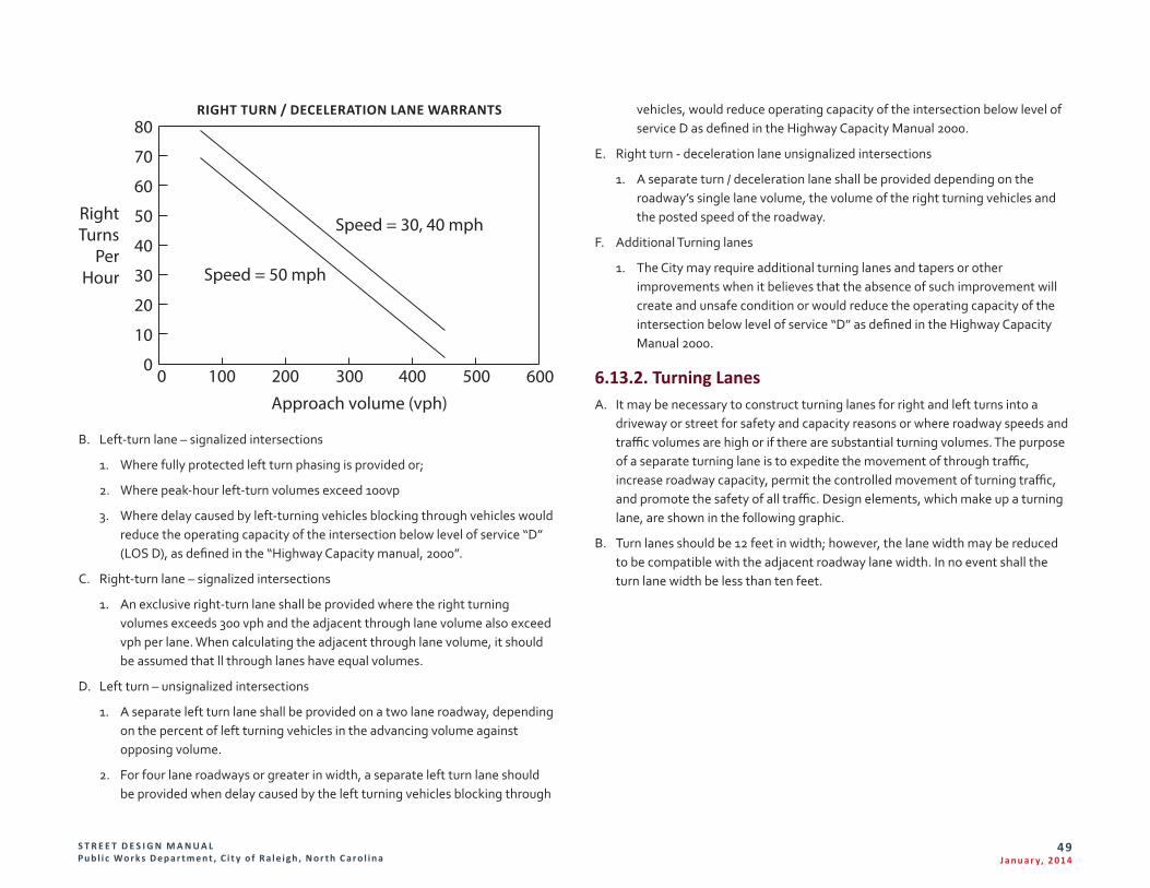
S T R E E T D E S I G N M A N U A L Pu b l i c Wo r k s D e p a r t m e n t , C i t y o f R a l e i g h , N o r t h C a r o l i n a
49J a n u a r y, 2 014
0
10
20
30
40
50
60
70
80
100 200 300 400 500 6000
Speed = 30, 40 mph
Speed = 50 mph
Approach volume (vph)
RIGHT TURN / DECELERATION LANE WARRANTS
B. Left-turn lane – signalized intersections
1. Where fully protected left turn phasing is provided or;
2. Where peak-hour left-turn volumes exceed 100vp
3. Where delay caused by left-turning vehicles blocking through vehicles would reduce the operating capacity of the intersection below level of service “D” (LOS D), as defined in the “Highway Capacity manual, 2000”.
C. Right-turn lane – signalized intersections
1. An exclusive right-turn lane shall be provided where the right turning volumes exceeds 300 vph and the adjacent through lane volume also exceed vph per lane. When calculating the adjacent through lane volume, it should be assumed that ll through lanes have equal volumes.
D. Left turn – unsignalized intersections
1. A separate left turn lane shall be provided on a two lane roadway, depending on the percent of left turning vehicles in the advancing volume against opposing volume.
2. For four lane roadways or greater in width, a separate left turn lane should be provided when delay caused by the left turning vehicles blocking through
vehicles, would reduce operating capacity of the intersection below level of service D as defined in the Highway Capacity Manual 2000.
E. Right turn - deceleration lane unsignalized intersections
1. A separate turn / deceleration lane shall be provided depending on the roadway’s single lane volume, the volume of the right turning vehicles and the posted speed of the roadway.
F. Additional Turning lanes
1. The City may require additional turning lanes and tapers or other improvements when it believes that the absence of such improvement will create and unsafe condition or would reduce the operating capacity of the intersection below level of service “D” as defined in the Highway Capacity Manual 2000.
6.13.2. Turning LanesA. It may be necessary to construct turning lanes for right and left turns into a
driveway or street for safety and capacity reasons or where roadway speeds and traffic volumes are high or if there are substantial turning volumes. The purpose of a separate turning lane is to expedite the movement of through traffic, increase roadway capacity, permit the controlled movement of turning traffic, and promote the safety of all traffic. Design elements, which make up a turning lane, are shown in the following graphic.
B. Turn lanes should be 12 feet in width; however, the lane width may be reduced to be compatible with the adjacent roadway lane width. In no event shall the turn lane width be less than ten feet.
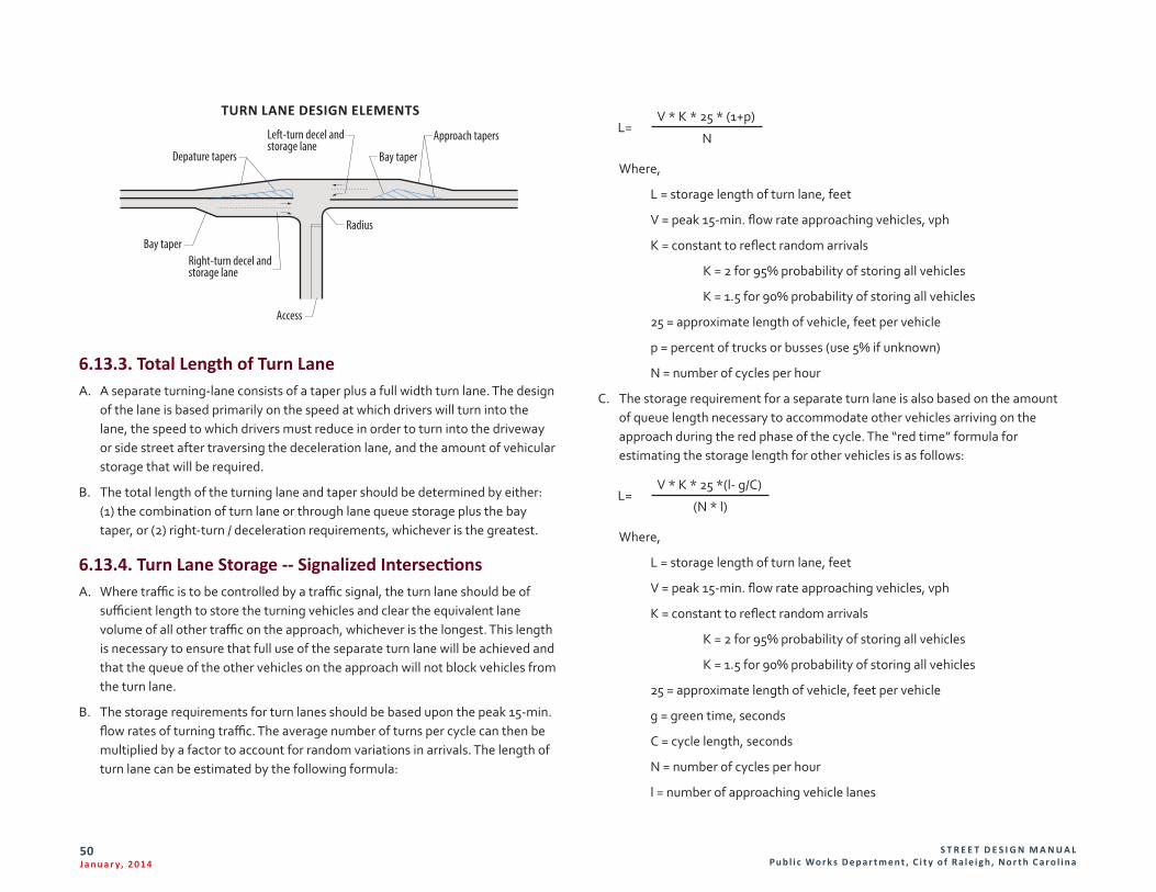
S T R E E T D E S I G N M A N U A L Pu b l i c Wo r k s D e p a r t m e n t , C i t y o f R a l e i g h , N o r t h C a r o l i n a
50J a n u a r y, 2 014
Approach tapers
Depature tapers Bay taper
Radius
Access
Bay taper
Left-turn decel andstorage lane
Right-turn decel andstorage lane
TURN LANE DESIGN ELEMENTS
6.13.3. Total Length of Turn LaneA. A separate turning-lane consists of a taper plus a full width turn lane. The design
of the lane is based primarily on the speed at which drivers will turn into the lane, the speed to which drivers must reduce in order to turn into the driveway or side street after traversing the deceleration lane, and the amount of vehicular storage that will be required.
B. The total length of the turning lane and taper should be determined by either: (1) the combination of turn lane or through lane queue storage plus the bay taper, or (2) right-turn / deceleration requirements, whichever is the greatest.
6.13.4. Turn Lane Storage -- Signalized IntersectionsA. Where traffic is to be controlled by a traffic signal, the turn lane should be of
sufficient length to store the turning vehicles and clear the equivalent lane volume of all other traffic on the approach, whichever is the longest. This length is necessary to ensure that full use of the separate turn lane will be achieved and that the queue of the other vehicles on the approach will not block vehicles from the turn lane.
B. The storage requirements for turn lanes should be based upon the peak 15-min. flow rates of turning traffic. The average number of turns per cycle can then be multiplied by a factor to account for random variations in arrivals. The length of turn lane can be estimated by the following formula:
L=V * K * 25 * (1+p)
N
Where,
L = storage length of turn lane, feet
V = peak 15-min. flow rate approaching vehicles, vph
K = constant to reflect random arrivals
K = 2 for 95% probability of storing all vehicles
K = 1.5 for 90% probability of storing all vehicles
25 = approximate length of vehicle, feet per vehicle
p = percent of trucks or busses (use 5% if unknown)
N = number of cycles per hour
C. The storage requirement for a separate turn lane is also based on the amount of queue length necessary to accommodate other vehicles arriving on the approach during the red phase of the cycle. The “red time” formula for estimating the storage length for other vehicles is as follows:
L=V * K * 25 *(l- g/C)
(N * l)
Where,
L = storage length of turn lane, feet
V = peak 15-min. flow rate approaching vehicles, vph
K = constant to reflect random arrivals
K = 2 for 95% probability of storing all vehicles
K = 1.5 for 90% probability of storing all vehicles
25 = approximate length of vehicle, feet per vehicle
g = green time, seconds
C = cycle length, seconds
N = number of cycles per hour
l = number of approaching vehicle lanes
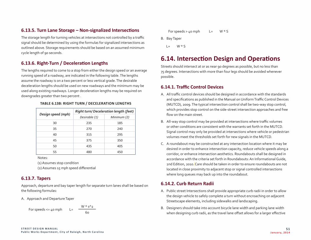
S T R E E T D E S I G N M A N U A L Pu b l i c Wo r k s D e p a r t m e n t , C i t y o f R a l e i g h , N o r t h C a r o l i n a
51J a n u a r y, 2 014
6.13.5. Turn Lane Storage – Non-signalized IntersectionsThe storage length for turning vehicles at intersections not controlled by a traffic signal should be determined by using the formulas for signalized intersections as outlined above. Storage requirements should be based on an assumed minimum cycle length of 90 seconds.
6.13.6. Right-Turn / Deceleration LengthsThe lengths required to come to a stop from either the design speed or an average running speed of a roadway, are indicated in the following table. The lengths assume the roadway is on a two percent or less vertical grade. The desirable deceleration lengths should be used on new roadways and the minimum may be used along existing roadways. Longer deceleration lengths may be required on downgrades greater than two percent .
TABLE 6.13B: RIGHT TURN / DECELERATION LENGTHS
Design speed (mph)Right turn/ Deceleration length (feet)
Desirable (1) Minimum (2)
30 235 185
35 270 240
40 315 295
45 375 350
50 435 405
55 480 450
Notes: (1) Assumes stop condition (2) Assumes 15 mph speed differential
6.13.7. TapersApproach, departure and bay taper length for separate turn lanes shall be based on the following formulas:
A. Approach and Departure Taper
For speeds <= 40 mph L=W * s^2
60
For speeds > 40 mph L= W * S
B. Bay Taper
L= W * S
6.14. Intersection Design and OperationsStreets should intersect at or as near 90 degrees as possible, but no less than 75 degrees. Intersections with more than four legs should be avoided whenever possible.
6.14.1. Traffic Control DevicesA. All traffic control devices should be designed in accordance with the standards
and specifications as published in the Manual on Uniform Traffic Control Devices (MUTCD), 2009. The typical intersection control shall be two-way stop control, which provides stop control on the side-street intersection approaches and free flow on the main street.
B. All-way stop control may be provided at intersections where traffic volumes or other conditions are consistent with the warrants set forth in the MUTCD. Signal control may only be provided at intersections where vehicle or pedestrian volumes meet the thresholds set forth for new signals in the MUTCD.
C. A roundabout may be constructed at any intersection location where it may be desired in order to enhance intersection capacity, reduce vehicle speeds along a corridor, or enhance intersection aesthetics. Roundabouts shall be designed in accordance with the criteria set forth in Roundabouts: An Informational Guide, 2nd Edition, 2010. Care should be taken in order to ensure roundabouts are not located in close proximity to adjacent stop or signal controlled intersections where long queues may back up into the roundabout.
6.14.2. Curb Return RadiiA. Public street Intersections shall provide appropriate curb radii in order to allow
the design vehicle to safely complete a turn without encroaching on adjacent Streetscape elements, including sidewalks and landscaping.
B. Designers should take into account bicycle lane width and parking lane width when designing curb radii, as the travel lane offset allows for a larger effective
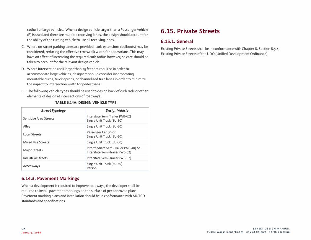
S T R E E T D E S I G N M A N U A L Pu b l i c Wo r k s D e p a r t m e n t , C i t y o f R a l e i g h , N o r t h C a r o l i n a
52J a n u a r y, 2 014
radius for large vehicles. When a design vehicle larger than a Passenger Vehicle (P) is used and there are multiple receiving lanes, the design should account for the ability of the turning vehicle to use all receiving lanes.
C. Where on-street parking lanes are provided, curb extensions (bulbouts) may be considered, reducing the effective crosswalk width for pedestrians. This may have an effect of increasing the required curb radius however, so care should be taken to account for the relevant design vehicle.
D. Where intersection radii larger than 25 feet are required in order to accommodate large vehicles, designers should consider incorporating mountable curbs, truck aprons, or channelized turn lanes in order to minimize the impact to intersection width for pedestrians.
E. The following vehicle types should be used to design back of curb radii or other elements of design at intersections of roadways:
TABLE 6.14A: DESIGN VEHICLE TYPE
Street Typology Design Vehicle
Sensitive Area Streets Interstate Semi Trailer (WB-62)Single Unit Truck (SU-30)
Alley Single Unit Truck (SU-30)
Local Streets Passenger Car (P) orSingle Unit Truck (SU-30)
Mixed Use Streets Single Unit Truck (SU-30)
Major Streets Intermediate Semi-Trailer (WB-40) orInterstate Semi-Trailer (WB-62)
Industrial Streets Interstate Semi-Trailer (WB-62)
Accessways Single Unit Truck (SU-30)Person
6.14.3. Pavement MarkingsWhen a development is required to improve roadways, the developer shall be required to install pavement markings on the surface of per approved plans. Pavement marking plans and installation should be in conformance with MUTCD standards and specifications.
6.15. Private Streets6.15.1. GeneralExisting Private Streets shall be in conformance with Chapter 8, Section 8.5.4, Existing Private Streets of the UDO (Unified Development Ordinance).
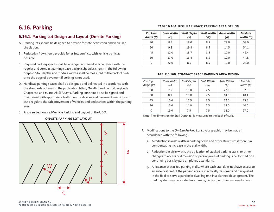
S T R E E T D E S I G N M A N U A L Pu b l i c Wo r k s D e p a r t m e n t , C i t y o f R a l e i g h , N o r t h C a r o l i n a
53J a n u a r y, 2 014
6.16. Parking 6.16.1. Parking Lot Design and Layout (On-site Parking)A. Parking lots should be designed to provide for safe pedestrian and vehicular
circulation.
B. Pedestrian flow should provide for as few conflicts with vehicle traffic as possible.
C. Required parking spaces shall be arranged and sized in accordance with the regular and compact parking space design schedules shown in the following graphic. Stall depths and module widths shall be measured to the back of curb or to the edge of pavement if curbing is not used.
D. Handicap parking spaces shall be designed and delineated in accordance with the standards outlined in the publication titled, “North Carolina Building Code Chapter 10 and 11 and ANSI A 117.1. Parking lots should also be signed and maintained with appropriate traffic control devices and pavement markings so as to regulate the safe movement of vehicles and pedestrians within the parking area.
E. Also see Section 7.1.6 Vehicle Parking and Layout of the UDO.
B
S
S
A
P
C
W
ON-SITE PARKING LOT LAYOUT
TABLE 6.16A: REGULAR SPACE PARKING AREA DESIGN
Parking Angle (P)
Curb Width (C)
Stall Depth (S)
Stall Width (W)
Aisle Width (A)
Module Width (B)
90 8.5 18.0 8.5 22.0 58.0
60 9.8 19.8 8.5 14.5 54.1
45 12.0 18.7 8.5 12.0 49.4
30 17.0 16.4 8.5 12.0 44.8
0 22.0 8.5 8.5 12.0 28.0
TABLE 6.16B: COMPACT SPACE PARKING AREA DESIGN
Parking Angle (P)
Curb Width (C)
Stall Depth (S)
Stall Width (W)
Aisle Width (A)
Module Width (B)
90 7.5 15.0 7.5 22.0 52.0
60 8.7 16.8 7.5 14.5 48.1
45 10.6 15.9 7.5 12.0 43.8
30 15.0 14.0 7.5 12.0 40.0
0 19.0 7.5 7.5 12.0 27.0
Note: The dimension for Stall Depth (S) is measured to the back of curb.
F. Modifications to the On-Site Parking Lot Layout graphic may be made in accordance with the following:
1. A reduction in aisle width in parking decks and other structures if there is a compensating increase in the stall width.
2. Reductions in aisle width, the utilization of stacked parking stalls, or other changes to access or dimension of parking areas if parking is performed on a continuing basis by paid employee attendants.
3. Allowance of stacked parking stalls, where each stall does not have access to an aisle or street, if the parking area is specifically designed and designated in the field to serve a particular dwelling unit in a planned development. The parking stall may be located in a garage, carport, or other enclosed space.
S T R E E T D E S I G N M A N U A L Pu b l i c Wo r k s D e p a r t m e n t , C i t y o f R a l e i g h , N o r t h C a r o l i n a
54J a n u a r y, 2 014
6.16.2. On-Street Parking (Public Parking Spaces)On-street parking shall be parallel, angular (60 degree) or perpendicular. On-street parking shall be provided in accordance with the following table for dimensions.
TABLE 6.16C: ON-STREET PARKING DIMENSIONS
Parking Angle (P)
Curb Width (C)
Stall Depth (S)
Stall Width
(W)
Stall Length (L)
Module Width (B)
Stall Length (L)
90 8.5 18.0 8.5 18.0 52.0 15.0
60 9.8 20.0 8.5 18.0 56.0 15.0
0 22.0 8.0 8.5 18.0 48.1 15.0
6.17. Streetscape Design and OperationsConsiderations in Streetscape design include sidewalk width, slope, furniture accommodation, utilities, landscaping, and building access. Primary guidance on best practices regarding universal accessibility in the Streetscape is available via the US Access Board’s draft Public Right-of-Way Accessibility Guidelines (PROWAG), as approved in 2012, as well as related Americans with Disabilities Act Accessibility Guidelines (ADAAG) for transportation facilities. The information in this chapter is drawn from the aforementioned guidelines, ITE manual on Designing Walkable Urban Thoroughfares, Raleigh UDO, and other resources.
6.17.1. StreetscapeA. The required streetscape is determined by the zoning district or the
designated frontage. The Streetscapes are described in the UDO in Chapter 8. Subdivision & Site Plan Standards, Section 8.5.2.
B. More information can be found in Section 8.5.2 (Streetscape Types) of the UDO.
1. Frontage: The frontages are defined in Article 3.4 (Frontage Requirements) of the UDO. Listed below are the different types of frontages.
a. Parkway (-PK)
b. Detached (-DE)
c. Parking Limited (-PL)
d. Green (-GR)
e. Urban Limited (-UL)
f. Urban General (-UG)
g. Shopfront (-SH)
2. Zoning District: The applicable zoning district
3. Width: Defines the maximum Streetscape width
4. Streetscape: defines all the facilities placed in the area
5. General: Defines Walkway type, Planting type and tree spacing
S T R E E T D E S I G N M A N U A L Pu b l i c Wo r k s D e p a r t m e n t , C i t y o f R a l e i g h , N o r t h C a r o l i n a
55J a n u a r y, 2 014
6.17.2. Adopted Streetscape Plans A. In the event an adopted streetscape plan regulates streetscape improvements,
the adopted Plan shall control. The adopted streetscape plans are contained within the Raleigh Street Design Manual.
B. The requirements of this Article are intended to serve as minimum standards. Where a streetscape plan adopted before the effective date of this UDO sets a lower standard, the standard in this Article shall prevail.
C. The City Council may modify an adopted Streetscape Plan following written notice to property owners along the street.
D. The following adopted streetscape plans must be followed in place of the streetscape types in Sec. 8.5.2 of the UDO:
1. Cameron Village Streetscape and Parking Plan
2. Cameron Village Streetscape and Parking Plan Amendment
3. Downtown Streetscape Master Plan
4. Glenlake Office Park Streetscape & Parking Plan
5. Glenwood South Streetscape & Parking Plan
6. Hillsborough Morgan Streetscape & Parking
7. Oakwood Mordecai Business District Streetscape Plan
8. Peace Streetscape & Parking Plan
9. Promenade at Crabtree Streetscape & Parking Plan
10. Southeast Raleigh Streetscape Master Plan
11. Stanhope Center Streetscape and Parking Plan
12. University Village Streetscape Plan on Hillsborough Street
E. The requirements of this Article are intended to serve as minimum standards. Where a streetscape plan adopted before the effective date of this UDO sets a lower standard, the standard in this Article shall prevail.
6.18. Street Trees6.18.1. Street Tree Plantings in an Urban SettingThe Parks and Recreation Department is responsible for plan review, inspection, monitoring and enforcement associated with tree planting and maintenance on property owned or controlled by the City. Tree related activities are conducted in adherence to City of Raleigh Municipal Code Trees and Vegetation, Part 9 Chapter 8 and the City Tree Manual. Where the Transportation Manual deviates from the referenced materials the Municipal Code Part 9 Chapter 8 shall take precedence.
A. Development and Landscape Plan Requirements
1. The Urban Forester or designee shall review all site plans with trees in the right of way and on city owned or controlled property. This application process describes the requirements for plan review, permitting, tree protection, standard specifications, tree quality, installation and maintenance.
2. Where development abuts a street controlled by the North Carolina Department of Transportation trees may not be required or will fall under the landscape requirements of the state. The city is still required to review and approve all proposed trees in the right of way.
B. Application Process
This is the application process for activities impacting city trees. Impacts include but are not limited to planting, removal, pruning, trenching, boring, excavating, filling, fertilizing, treating for disease or insects, installing decorations and planting.
1. Submit Tree Impact Permit Request to the Urban Forester
2. Additional documentation required
a. Site and/or Landscape Plan
i. Identify property boundaries and rights of way
ii. Label streets and other plan elements
iii. Overhead utilities and lighting plan
iv. Identify trees for demolition and preservation
v. Depict the required site distance triangles
S T R E E T D E S I G N M A N U A L Pu b l i c Wo r k s D e p a r t m e n t , C i t y o f R a l e i g h , N o r t h C a r o l i n a
56J a n u a r y, 2 014
vi. Depict tree protection zones and fencing detail
vii. Tree species including botanical name, installation size and counts
viii. Urban tree pit detail and subsurface root treatment if applicable with 600cuft minimum soil requirement.
ix. Adherence to tree quality specifications and detail
x. Adherence to tree planting specifications and detail
xi. Tree Protection Plan (waived if no trees impacted within Critical Root Zone on site)
6.18.2. Tree Infrastructure, Installation and Maintenance StandardsA. Trees in sidewalks, pits and grates and tree lawn
1. A tree maintenance fee shall be assessed at the time of permit issuance for each street tree to be installed. This shall be included in the Fee Schedule
2. Tree Grate
a. 4 feet x 6 feet gray iron, ADA compliant
b. Tree grates shall have a provision for trunk expansion of the tree, such as pop out concentric rings in the grate around the trunk
c. No utilities or electrical conduits are permitted within the tree pit or grate (utilities may run below and through the subsurface root expansion infrastructure)
d. Trees shall be centered in the pit
e. Tree pits shall accommodate a depth of 3 feet of planting soil
f. High quality planting soil shall be used in the pit directly below the grate
g. Drainage shall be provided
3. Tree Lawn
a. Minimum 6 fee wide tree lawn
b. Trees centered in area
c. No utilities or electrical conduits are permitted within the tree lawn (utilities may run below and through the subsurface root expansion infrastructure)
d. 600 cubic feet of organic soil in the immediate area where the tree is to be placed
B. Required Subsurface Root Expansion
1. High quality top soil or structural soil shall be used to accomplish the soil volume requirement.
2. Require minimum 600 cubic feet.
3. Exceptions and design alternatives are encouraged to achieve soil volume: Urban Forester review required. Designs that group trees and connect root spaces will be favored as well as the introduction of LID materials and technology
4. Select one or more options below
a. Structural Soil
b. Subsurface Soil containment structure
c. Minimum 6 paths from each tree, 3 on each side 20’ minimum extension for each path. Connect to adjacent pit path.
d. Suspended pavement
5. When root expansion paths extend under sidewalks, ensure minimum density requirements are met.
C. Planting Standards
1. All plant material and installation work shall conform to the standards detailed in the following documents:
a. American National Standards for Tree Care Operations, ANSI A300. American National Standards Institute, 11 West 42nd Street, New York, N.Y. 10036
b. American National Standard for Nursery Stock, ANSI Z60.1. American Nursery and Landscape Association, 1250 Eye Street. NW, Suite 500, Washington, D.C. 20005
c. Hortus Third, The Staff of the L.H. Bailey Hortorium. 1976. MacMillan Publishing Co., New York
S T R E E T D E S I G N M A N U A L Pu b l i c Wo r k s D e p a r t m e n t , C i t y o f R a l e i g h , N o r t h C a r o l i n a
57J a n u a r y, 2 014
2. All plant material shall be free of all pests, diseases, and cankers, in healthy condition, and free of mechanical damage at the time of planting.
3. Balled and Burlapped (B&B) Street Trees
a. Trees designated B&B shall be properly dug with firm, natural balls of soil retaining as many fibrous roots as possible, in sizes and shapes as specified in the American Standard for Nursery Stock ANSI Z60.1.
b. Root balls shall be firmly wrapped with nonsynthetic, rottable burlap and secured with nails and heavy, nonsynthetic twine.
c. The root collar shall be apparent at surface of ball, or the contractor will be responsible for removing excess soil from the top of the rootball. The tree shall be planted at grade; no more than 2” above grade and shall not be planted below grade.
d. Remove all burlap, lacing, and wire basket from at least the top 1/2 of the rootball and discard from planting hole.
e. Do not maneuver by trunk. Handle by root ball only.
4. Containerized material
a. Trees designated containerized shall have firm, natural balls of soil retaining as many fibrous roots as possible, in sizes and shapes as specified in the American Standard for Nursery Stock ANSI Z60.1.
b. The root collar shall be apparent at surface of ball, or the contractor will be responsible for removing excess soil from the top of the rootball. The tree shall be planted at grade; no more than 2” above grade and shall not be planted below grade.
c. Remove container prior to planting.
5. Installation size for right of way trees
a. 3 inch caliper, 10 feet tall for large maturing or shade trees
b. Understory trees shall be a minimum of 1.5 inch caliper for single stem and 6 feet tall for both single and multi-stemmed trees.
D. Maintenance and Warrantee Standards
1. It is the adjacent property owner’s responsibility to maintain the mulch ring or tree grate around trees in the right of way and prevent string trimmer or mower damage.
2. A 2 year warrantee and maintenance period is required after the final inspection of permitted planting.
3. Tree Grates
a. Maintain grates free of weeds, trash and debris.
b. Replenish gravel as needed to maintain an even surface. Gravel shall match existing material; typically gray pea gravel/ #67 washed stone gravel.
c. Notify Urban Forester if the tree grate is girdling tree or causing damage to tree.
4. Mulch- organic
a. Mulch shall not exceed 3 inches in depth and will remain a minimum of 3 inches away from the base of any given tree.
b. Mulch shall be the responsibility of the owner.
5. Staking
a. Do not stake unless the tree becomes unstable or it is a high wind area
b. If stability is a concern, remove all staking material after 1 year
6. Watering Instructions
a. 2 year watering and maintenance required (minimum)
b. After installation trees shall be thoroughly soaked and watered at least twice per week until establishment.
c. Use a slow flow hose end device and water each tree at the base for several minutes. Commercially available water bags are acceptable but the root ball shall be soaked as well as filling the bag.
d. Watering volumes should be based upon delivery of 1 inch of moisture / week to the tree if precipitation does not meet that amount during the active growing season defined as April 15th through November 1st.
E. Tree Pruning
1. All tree pruning shall be done by or under the supervision of an ISA Certified Arborist or City approved professional.
2. ANSI A-300 Pruning Standards shall be strictly adhered to.
S T R E E T D E S I G N M A N U A L Pu b l i c Wo r k s D e p a r t m e n t , C i t y o f R a l e i g h , N o r t h C a r o l i n a
58J a n u a r y, 2 014
F. Root Pruning
1. Area for root pruning must be approved by an ISA Certified Arborist to prevent a hazardous tree condition.
2. Acceptable methods of cutting are with sharp hand pruners, loppers, handsaw or hydraulic tools. Implement must leave a clean cut.
3. If excavation causes pruned roots over 1.5” in diameter to remain exposed for more than 24 hours, roots on tree side shall be kept moist. Backfill with topsoil, moist mulch, or drape with wet burlap.
4. Where concrete is poured adjacent to pruned roots heavy duty plastic shall be installed against the tree side of the pruned roots to prevent uptake (toxic to tree).
G. Tree Protection
1. Tree protection fencing shall be installed at a minimum radius of the Critical Root Zone (CRZ) of trees (CRZ defined as radius 1.25’ (ft) per caliper inch at dbh from trunk of tree)
2. Signage necessary every 50’ Do Not Enter Tree Protection Area
3. If construction occurs within the (CRZ) at least 12” of mulch shall be placed and/or logging mats or plywood where machinery maneuvers to reduce soil compaction in this zone.
4. The tree protection fencing shall not be violated for the entire duration of the project without approval from arborist.
5. There will be zero tolerance for storing or parking vehicles, supplies, or equipment under trees.
H. Tree Replacement
1. Trees shall be replaced in the next planting season if they are more than 25% dead, in rapid decline, are infested by insects or disease, have lost the natural shape due to dead branches, excessive pruning including vandalism, inadequate or improper maintenance, or are failing due to other causes.
2. Replacement trees installed after the 1st year of the 2 year warrantee/maintenance period shall get a full 1 year of warrantee/maintenance from the time of planting.
3. Dead, dying, diseased or vandalized trees that are destroyed shall be removed within 15 days.
4. Species may be changed with approval from Urban Forester or designee.
6.19. Transit6.19.1. OverviewThe Capital Area Transit Program (CAT) has the responsibility for providing transit services for the City of Raleigh and surrounding areas. CAT encourages developers and local municipalities to follow guidelines and recommendations set forth in the Passenger Amenity Guidelines and Transit Design Standards Guidebook and to work with CAT staff when planning new developments or changes to existing developments. This teamwork and collaboration will create transit-oriented environments that will meet the City’s initiative to foster Complete Streets infrastructure and to support the mandates of the Americans with Disabilities Act (ADA).
6.19.2. Planning PhaseThe following questions can be used in planning and evaluating accessibility of a development to public transit and a new or improved bus stop. Proposed developments can be evaluated by the responses provided. A “Yes” response is required and will determine if the proposed development will accommodate transit vehicles and will provide access to public transit. Refer to the Passenger Amenity Guidelines and Transit Design Standards Guidebook for appropriate layout and design suggestions, if a “Yes” is not received. CAT planning staff will review all development sites and provide transit related design recommendations and technical assistance if additional assistance in required.
_____ Is this a Major Activity Center (hospitals and universities)
_____ Is this a High Density development
_____ Is this a Medium Density development
_____ Is this a Low/Rural Development
_____ Will roadways within and around the development be accessible to buses?
_____ Do radii for driveways and intersections meet bus turning radius designs?
S T R E E T D E S I G N M A N U A L Pu b l i c Wo r k s D e p a r t m e n t , C i t y o f R a l e i g h , N o r t h C a r o l i n a
59J a n u a r y, 2 014
_____ Are roadway lane widths 11’ wide?
_____ Are curb and gutter provided?
_____ Are vertical grades 6% or less?
_____ Are residential developments designed with a central collector street that will provide access for buses?
_____ Have bus stop locations near the proposed development been identified by CAT planning staff?
_____ Has CAT planning staff reviewed the proposed transit stop location?
_____ Are passenger amenities such as a shelter or bench required as part of this development?
_____ Are sidewalks, ramps, bus pads and other development features designed to meet ADA guidelines?
_____ Are direct access paths provided from building entrances to the bus stop?
_____ Have the plans been reviewed and approved by CAT planning staff for all transit related amenities?
6.19.3. Design PhaseOnce the planning work has been completed and approved by CAT planning staff, design efforts may begin. Construction Standard Drawings, shown on the following pages in Appendix A, T-1 through T-12, are available to assist in the design and layout of required bus stop amenities. Design elements will include the following steps:
A. Provide enough topographic survey information to properly layout the site. Include nearest intersection and/or driveway turnouts to determine if sight distance and clear recovery requirements are in violation. Sight distance and clear recovery requirements will follow the guidelines of the AASHTO “Green Book” - A Policy on Geometric Design of Highways and Streets.
B. Provide utility information and show street rights-of-way and property lines to determine if easements will be required.
C. Provide CAT planning staff with twenty-five percent (25%) design plans with all amenities approved during the planning phase. Design plans should
include existing conditions topographic survey to determine grades of pad and surrounding areas meet ADA and if retaining walls are needed.
D. Prepare NCDOT Encroachment Agreements (Form R/W 16.1A) and provide appropriate number of copies of plans to Division for review. Coordinate with NCDOT Division 5, District 1 Office.
E. Prepare Easement Exhibits on legal size sheet, sealed and signed by a North Carolina Registered Surveyor and provide to City Real Estate Department.
F. Provide technical specifications for all construction items to be reviewed by the City to ensure that they meet the current standards.
6.20. Solid Waste DesignThis section in the Transportation manual provides guidance for the access standards. Further information can be found in the Solid Waste Collection Design Manual (Part 7, Chapter 2 of the Raleigh City Code).
6.20.1. General Access StandardsA. All parking areas to be directly accessed by solid waste collection vehicles must
maintain all Internal inside curb radii at a min. 28’. All parking lot aisles that will be traversed by solid waste collection vehicles must meet the standards of the City of Raleigh Standard Details. Site plans must designate the ingress and egress routes for solid waste collection vehicles.
B. Access to collection devices must be by internal driveways and parking areas within a site. No collection device may be accessed directly from a public street, and no backing movement from an internal collection device may encroach into a public right of way. Exemption of this condition for properties within the Downtown District may be authorized in writing by the Solid Waste Services Director.
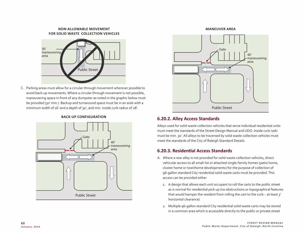
S T R E E T D E S I G N M A N U A L Pu b l i c Wo r k s D e p a r t m e n t , C i t y o f R a l e i g h , N o r t h C a r o l i n a
60J a n u a r y, 2 014
Public Street
30’maneuveringarea
NON-ALLOWABLE MOVEMENT FOR SOLID WASTE COLLECTION VEHICLES
C. Parking areas must allow for a circular through movement wherever possible to avoid back-up movements. Where a circular through movement is not possible, maneuvering space in front of any dumpster as noted in the graphic below must be provided (30’ min.). Backup and turnaround space must be in an aisle with a minimum width of 16’ and a depth of 30’, and min. inside curb radius of 28’.
Public Street
40’maneuveringarea
Gate
BACK-UP CONFIGURATION
Public Street
40’maneuveringarea
Gate
MANEUVER AREA
6.20.2. Alley Access StandardsAlleys used for solid waste collection vehicles that serve individual residential units must meet the standards of the Street Design Manual and UDO. Inside curb radii must be min. 30’. All alleys to be traversed by solid waste collection vehicles must meet the standards of the City of Raleigh Standard Details.
6.20.3. Residential Access StandardsA. Where a rear alley is not provided for solid waste collection vehicles, direct
vehicular access to all small-lot or attached single-family homes (patio home, cluster home or townhome developments) for the purpose of collection of 96-gallon standard City residential solid waste carts must be provided. This access can be provided either
1. A design that allows each unit occupant to roll the carts to the public street as is normal for residential pick-up (no obstructions or topographical features that would hamper the resident from rolling the cart to the curb – at least 3’ horizontal clearance)
2. Multiple 96-gallon standard City residential solid waste carts may be stored in a common area which is accessible directly to the public or private street
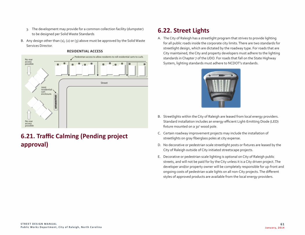
S T R E E T D E S I G N M A N U A L Pu b l i c Wo r k s D e p a r t m e n t , C i t y o f R a l e i g h , N o r t h C a r o l i n a
61J a n u a r y, 2 014
3. The development may provide for a common collection facility (dumpster) to be designed per Solid Waste Standards
B. Any design other than (1), (2) or (3) above must be approved by the Solid Waste Services Director.
Pedestrian access to allow residents to roll residential carts to curb.
Joint residentialcart enclosure.
No rearaccesspossible
No rearaccesspossible
Street
RESIDENTIAL ACCESS
6.21. Traffic Calming (Pending project approval)
6.22. Street LightsA. The City of Raleigh has a streetlight program that strives to provide lighting
for all public roads inside the corporate city limits. There are two standards for streetlight design, which are dictated by the roadway type. For roads that are City maintained, the City and property developers must adhere to the lighting standards in Chapter 7 of the UDO. For roads that fall on the State Highway System, lighting standards must adhere to NCDOT’s standards.
B. Streetlights within the City of Raleigh are leased from local energy providers. Standard installation includes an energy efficient Light-Emitting Diode (LED) fixture mounted on a 30' wood pole.
C. Certain roadway improvement projects may include the installation of streetlights on gray fiberglass poles at city expense.
D. No decorative or pedestrian scale streetlight posts or fixtures are leased by the City of Raleigh outside of City initiated streetscape projects.
E. Decorative or pedestrian scale lighting is optional on City of Raleigh public streets, and will not be paid for by the City unless it is a City driven project. The developer and/or property owner will be completely responsible for up-front and ongoing costs of pedestrian scale lights on all non-City projects. The different styles of approved products are available from the local energy providers.
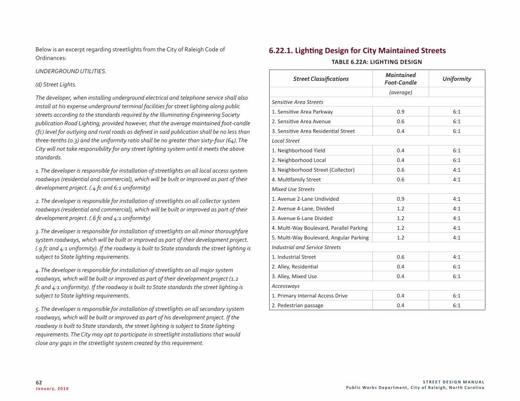
S T R E E T D E S I G N M A N U A L Pu b l i c Wo r k s D e p a r t m e n t , C i t y o f R a l e i g h , N o r t h C a r o l i n a
62J a n u a r y, 2 014
Below is an excerpt regarding streetlights from the City of Raleigh Code of Ordinances:
UNDERGROUND UTILITIES.
(d) Street Lights.
The developer, when installing underground electrical and telephone service shall also install at his expense underground terminal facilities for street lighting along public streets according to the standards required by the Illuminating Engineering Society publication Road Lighting; provided however, that the average maintained foot-candle (fc) level for outlying and rural roads as defined in said publication shall be no less than three-tenths (0.3) and the uniformity ratio shall be no greater than sixty-four (64). The City will not take responsibility for any street lighting system until it meets the above standards.
1. The developer is responsible for installation of streetlights on all local access system roadways (residential and commercial), which will be built or improved as part of their development project. (.4 fc and 6:1 uniformity)
2. The developer is responsible for installation of streetlights on all collector system roadways (residential and commercial), which will be built or improved as part of their development project. (.6 fc and 4:1 uniformity)
3. The developer is responsible for installation of streetlights on all minor thoroughfare system roadways, which will be built or improved as part of their development project. (.9 fc and 4:1 uniformity). If the roadway is built to State standards the street lighting is subject to State lighting requirements.
4. The developer is responsible for installation of streetlights on all major system roadways, which will be built or improved as part of their development project (1.2 fc and 4:1 uniformity). If the roadway is built to State standards the street lighting is subject to State lighting requirements.
5. The developer is responsible for installation of streetlights on all secondary system roadways, which will be built or improved as part of his development project. If the roadway is built to State standards, the street lighting is subject to State lighting requirements. The City may opt to participate in streetlight installations that would close any gaps in the streetlight system created by this requirement.
6.22.1. Lighting Design for City Maintained StreetsTABLE 6.22A: LIGHTING DESIGN
Street Classifications Maintained Foot-Candle
Uniformity
(average)
Sensitive Area Streets
1. Sensitive Area Parkway 0.9 6:1
2. Sensitive Area Avenue 0.6 6:1
3. Sensitive Area Residential Street 0.4 6:1
Local Street
1. Neighborhood Yield 0.4 6:1
2. Neighborhood Local 0.4 6:1
3. Neighborhood Street (Collector) 0.6 4:1
4. Multifamily Street 0.6 4:1
Mixed Use Streets
1. Avenue 2-Lane Undivided 0.9 4:1
2. Avenue 4-Lane, Divided 1.2 4:1
3. Avenue 6-Lane Divided 1.2 4:1
4. Multi-Way Boulevard, Parallel Parking 1.2 4:1
5. Multi-Way Boulevard, Angular Parking 1.2 4:1
Industrial and Service Streets
1. Industrial Street 0.6 4:1
2. Alley, Residential 0.4 6:1
3. Alley, Mixed Use 0.4 6:1
Accessways
1. Primary Internal Access Drive 0.4 6:1
2. Pedestrian passage 0.4 6:1
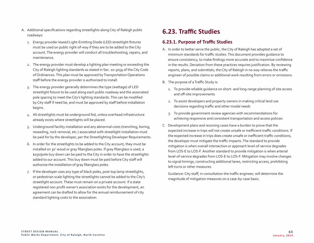
S T R E E T D E S I G N M A N U A L Pu b l i c Wo r k s D e p a r t m e n t , C i t y o f R a l e i g h , N o r t h C a r o l i n a
63J a n u a r y, 2 014
A. Additional specifications regarding streetlights along City of Raleigh public roadways:
1. Energy provider leased Light-Emitting Diode (LED) streetlight fixtures must be used on public right-of-way if they are to be added to the City account. The energy provider will conduct all troubleshooting, repairs, and maintenance.
2. The energy provider must develop a lighting plan meeting or exceeding the City of Raleigh lighting standards as stated in Sec. 10-3059 of the City Code of Ordinances. This plan must be approved by Transportation Operations staff before the energy provider is authorized to install.
3. The energy provider generally determines the type (wattage) of LED streetlight fixture to be used along each public roadway and the associated pole spacing to meet the City’s lighting standards. This can be modified by City staff if need be, and must be approved by staff before installation begins.
4. All streetlights must be underground fed, unless overhead infrastructure already exists where streetlights will be placed.
5. Underground facility installation and any abnormal costs (trenching, boring, reseeding, rock removal, etc.) associated with streetlight installation must be paid for by the developer, per the Streetlighting Developer Requirements.
6. In order for the streetlights to be added to the City account, they must be installed on 30’ wood or gray fiberglass poles. If gray fiberglass is used, a $250/pole buy down can be paid to the City in order to have the streetlights added to our account. This buy down must be paid before City staff will authorize the installation of gray fiberglass poles.
7. If the developer uses any type of black poles, post-top lamp streetlights, or pedestrian scale lighting the streetlights cannot be added to the City’s streetlight account. These must remain on a private account. If a state registered non-profit owner’s association exists for the development, an agreement can be drafted to allow for the annual reimbursement of city standard lighting costs to the association.
6.23. Traffic Studies6.23.1. Purpose of Traffic Studies A. In order to better serve the public, the City of Raleigh has adopted a set of
minimum standards for traffic studies. This document provides guidance to ensure consistency, to make findings more accurate and to maximize confidence in the results. Deviation from these practices requires justification. By reviewing reports, plans, and submittals, the City of Raleigh in no way relieves the traffic engineer of possible claims or additional work resulting from errors or omissions.
B. The purpose of a Traffic Study is:
1. To provide reliable guidance on short- and long-range planning of site access and off-site improvements
2. To assist developers and property owners in making critical land use decisions regarding traffic and other modal needs
3. To provide government review agencies with recommendations for achieving responsive and consistent transportation and access policies
C. Development plans and rezoning cases have a burden to prove that the expected increase in trips will not create unsafe or inefficient traffic conditions. If the expected increase in trips does create unsafe or inefficient traffic conditions, the developer must mitigate the traffic impacts. The standard to provide mitigation is when overall intersection or approach level-of-service degrades from LOS-E to LOS-F. Another standard to provide mitigation is when arterial level-of-service degrades from LOS-E to LOS-F. Mitigation may involve changes to signal timings, constructing additional lanes, restricting access, prohibiting left turns or other measures.
Guidance: City staff, in consultation the traffic engineer, will determine the magnitude of mitigation measures on a case-by-case basis.
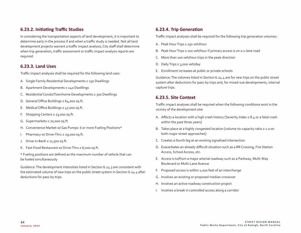
S T R E E T D E S I G N M A N U A L Pu b l i c Wo r k s D e p a r t m e n t , C i t y o f R a l e i g h , N o r t h C a r o l i n a
64J a n u a r y, 2 014
6.23.2. Initiating Traffic Studies In considering the transportation aspects of land development, it is important to determine early in the process if and when a traffic study is needed. Not all land development projects warrant a traffic impact analysis; City staff shall determine when trip generation, traffic assessment or traffic impact analysis reports are required.
6.23.3. Land Uses Traffic impact analyses shall be required for the following land uses:
A. Single Family Residential Developments ≥ 150 Dwellings
B. Apartment Developments ≥ 240 Dwellings
C. Residential Condo/Townhome Developments ≥ 300 Dwellings
D. General Office Buildings ≥ 64,000 sq.ft.
E. Medical Office Buildings ≥ 47,000 sq.ft.
F. Shopping Centers ≥ 23,000 sq.ft.
G. Supermarkets ≥ 20,000 sq.ft.
H. Convenience Market w/ Gas Pumps: 6 or more Fueling Positions*
I. Pharmacy w/ Drive-Thru ≥ 29,000 sq.ft.
J. Drive-In Bank ≥ 11,500 sq.ft.
K. Fast-Food Restaurant w/ Drive-Thru ≥ 6,000 sq.ft.
* Fueling positions are defined as the maximum number of vehicle that can be fueled simultaneously
Guidance: The development intensities listed in Section 6.24.3 are consistent with the estimated volume of new trips on the public street system in Section 6.24.4 after deductions for pass-by trips.
6.23.4. Trip Generation Traffic impact analyses shall be required for the following trip generation volumes:
A. Peak Hour Trips ≥ 150 veh/hour
B. Peak Hour Trips ≥ 100 veh/hour if primary access is on a 2-lane road
C. More than 100 veh/hour trips in the peak direction
D. Daily Trips ≥ 3,000 veh/day
E. Enrollment increases at public or private schools
Guidance: The volumes listed in Section 6.24.4 are for new trips on the public street system after deductions for pass-by trips and, for mixed-sue developments, internal capture trips.
6.23.5. Site Context Traffic impact analyses shall be required when the following conditions exist in the vicinity of the development site:
A. Affects a location with a high crash history [Severity Index ≥ 8.4 or a fatal crash within the past three years]
B. Takes place at a highly congested location [volume-to-capacity ratio ≥ 1.0 on both major street approaches]
C. Creates a fourth leg at an existing signalized intersection
D. Exacerbates an already difficult situation such as a RR Crossing, Fire Station Access, School Access, etc.
E. Access is to/from a major arterial roadway such as a Parkway, Multi-Way Boulevard or Multi-Lane Avenue
F. Proposed access is within 1,000 feet of an interchange
G. Involves an existing or proposed median crossover
H. Involves an active roadway construction project
I. Involves a break in controlled access along a corridor
S T R E E T D E S I G N M A N U A L Pu b l i c Wo r k s D e p a r t m e n t , C i t y o f R a l e i g h , N o r t h C a r o l i n a
65J a n u a r y, 2 014
6.23.6. Miscellaneous Applications Traffic impact analyses shall be required for:
A. Planned Development Districts
B. In response to Raleigh Planning Commission or Raleigh City Council concerns
Guidance: For rezoning applications, the basis of comparison for trip generation thresholds will be the difference between the maximum allowable land use intensity under current zoning compared to the maximum land use intensity under the proposed zoning. For site plans and subdivisions, the basis of comparison for trip generation thresholds should be the difference between trips generated by the site at the time of preliminary plan submittal versus the expected increase in roadway trips upon development of the site.
6.23.7. Study Area The extent of a traffic study depends on the location and size of the proposed development and the conditions prevailing in the surrounding area. It is recognized that an excessively large study area may unnecessarily increase costs, time and effort for the developer, the traffic engineer and City staff. Alternatively, an inappropriately small traffic study area may fail to include roadway segments and/or intersections that would need to be improved to accommodate the trips generated by a proposed development.
6.23.8. Access Points and Intersections A. Any traffic study that analyzes off-site impacts shall include all site access points
and major intersections (signalized and unsignalized) adjacent to the site.
B. Guidance: City staff (with input from the developer’s traffic engineer) will determine any additional areas to be included based on local or site-specific conditions, development size or neighborhood sensitivities. The study area boundaries may also be influenced by impacts other than pure capacity issues such as neighborhood cut-thru trips, known congestion issues, accident history, temporary anomalies in the existing roadway system that would influence travel patterns, long-range transportation planning goals, etc.
6.23.9. Traffic Study Scope It is critical that all parties discuss the traffic study early in the planning process. An understanding as to the level of detail and the assumptions required for analysis will be determined at that time. In addition to learning the study issues, coverage and level of detail, the traffic engineer must obtain and verify the following information:
1. Available traffic counts
2. Information about available transit, bicycle and pedestrian facilities
3. Committed and planned roadway improvements and the schedule for those improvements
4. Approved development and background traffic data
5. Applicable agency codes and policies
6. Existing congestion locations within the study area
7. Crash data for all intersections and/or street segments within the study area
8. Traffic signal timings
9. Committed and planned signal system improvements
10. Neighborhood sensitivities
11. Other traffic-related issues determined by City staff
Guidance: City staff will assist the traffic engineer in obtaining all information needed to initiate and complete the traffic study.
6.23.10. Traffic Model Analysis Programs Except for very simple cases, all traffic analyses shall be produced with special software programs that are designed specifically for traffic model applications. For software to be acceptable it must be based on the most current Highway Capacity Manual methods.
S T R E E T D E S I G N M A N U A L Pu b l i c Wo r k s D e p a r t m e n t , C i t y o f R a l e i g h , N o r t h C a r o l i n a
66J a n u a r y, 2 014
6.23.11. Preferred Analysis Programs A. Signalized intersection delay Synchro
B. Unsignalized intersection delay Synchro
C. Queuing and blocking SimTraffic
D. Roundabouts SimTraffic
E. Simulation SimTraffic
F. Actuated signal cycle variables SimTraffic
G. Arterial delay SimTraffic
H. Arterial travel time SimTraffic
I. Arterial speed and Level-of-Service SimTraffic
J. Network total stops SimTraffic
K. Network stops per vehicle SimTraffic
L. Network fuel consumed SimTraffic
M. Network air quality/vehicle emissions SimTraffic
N. Multimodal Level-of-Service Artplan
Guidance: Use of alternate analysis software must be approved by City staff; however the above software is not specifically endorsed by City staff. Other traffic analysis tools and programs will be considered on a case-by-case basis. City staff shall determine the appropriateness of the alternative models.
6.23.12. Existing Conditions Once all information listed in the study scope has been obtained, it is used to create an existing conditions traffic model. The existing conditions model will be used to create a foundation for assessing the land use and traffic impact changes over time. Thus it is critical that the existing conditions model be as accurate as possible.
6.23.13. Existing Conditions Data Requirements Traffic volumes shall reflect normal weekday and/or peak hour traffic conditions. When submitting a traffic study document for review, the traffic counts used for capacity analysis purposes shall have been taken no more than one year prior to the submittal date of the document. Exceptions to this standard can be approved on
a case-by-case basis. In some cases, it is necessary to conduct new traffic counts. Counts shall not be taken on holidays, when school is not in session, during adverse weather or when special events occur. The existing conditions model shall accurately reflect the current street and traffic control environment including, but not limited to:
A. Road geometry
B. Number and type of travel lanes
C. Auxiliary turning lanes, storage lengths and tapers
D. Medians and two-way left turn lanes
E. Traffic volumes, including heavy vehicles and pedestrians
F. Transit stops, exclusive bicycle lanes and on-street parking (when applicable)
G. Cycle length, signal offsets, splits and phase sequence
H. Detector layout and detector settings
I. Phase settings such as recall mode, volume-density settings, minimum green, maximum green and clearance times
J. Two-way and all-way stop control
K. Roundabouts and other unconventional intersections
Guidance: City staff will assist the traffic engineer in obtaining turning movement counts, existing signal plans and current signal timings from City of Raleigh archives.
6.23.14. Non-Site Traffic Forecast A. Estimates of non-site traffic are required to complete the analysis of horizon
year conditions. Non-site traffic volumes, when added to existing volumes, are typically known as Background Traffic. These estimates characterize the “base” conditions, i.e., traffic conditions prior to a site being redeveloped. Non-site traffic consists of two components: existing traffic volumes projected forward to the horizon year using an annual grow rate and trips generated by approved developments within or adjacent to the study area.
B. Projections of existing traffic volumes to the horizon year are dependent on an assumed annual growth rate. City staff (with input from the developer’s traffic engineer) will determine the appropriate growth rate based on information such as the Triangle Regional Traffic model, historical daily traffic volumes obtained from NCDOT, existing turning movement counts, previous traffic studies or other sources.
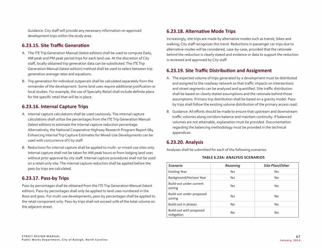
S T R E E T D E S I G N M A N U A L Pu b l i c Wo r k s D e p a r t m e n t , C i t y o f R a l e i g h , N o r t h C a r o l i n a
67J a n u a r y, 2 014
Guidance: City staff will provide any necessary information on approved development trips within the study area.
6.23.15. Site Traffic Generation A. The ITE Trip Generation Manual (latest edition) shall be used to compute Daily,
AM peak and PM peak period trips for each land use. At the discretion of City staff, locally obtained trip generation data can be substituted. The ITE Trip Generation Manual (latest edition) method shall be used to select between trip generation average rates and equations.
B. Trip generation for individual outparcels shall be calculated separately from the remainder of the development. Some land uses require additional justification or local studies. For example, the use of Specialty Retail shall include definite plans for the specific retail that will be in place.
6.23.16. Internal Capture Trips A. Internal capture calculations shall be used cautiously. The internal capture
calculations shall utilize the percentages from the ITE Trip Generation Manual (latest edition) to estimate the internal capture reduction percentage. Alternatively, the National Cooperative Highway Research Program Report 684 Enhancing Internal Trip Capture Estimates for Mixed-Use Developments can be used with concurrence of City staff.
B. Reductions for internal capture shall be applied to multi- or mixed-use sites only. Internal capture shall not be taken for AM peak hours or from lodging land uses without prior approval by city staff. Internal capture procedures shall not be used on a retail-only site. The internal capture reduction shall be applied before the pass-by trips are calculated.
6.23.17. Pass-by Trips Pass-by percentages shall be obtained from the ITE Trip Generation Manual (latest edition). Pass-by percentages shall only be applied to land uses numbered in the 800s and 900s. For multi-use developments, pass-by percentages shall be applied to the retail component only. Pass-by trips shall not exceed 10% of the total volume on the adjacent street.
6.23.18. Alternative Mode Trips Increasingly, site trips are made by alternative modes such as transit, bikes and walking; City staff recognizes this trend. Reductions in passenger car trips due to alternative modes will be considered, case-by-case, provided that the rationale behind the reduction is clearly stated and evidence or data to support the reduction is reviewed and approved by City staff.
6.23.19. Site Traffic Distribution and Assignment A. The expected volume of trips generated by a development must be distributed
and assigned to the roadway network so that traffic impacts on intersections and street segments can be analyzed and quantified. Site traffic distribution shall be based on clearly stated assumptions and the rationale behind those assumptions. Primary trip distribution shall be based on a gravity model. Pass-by trips shall follow the existing volume distribution of the primary access road.
B. Guidance: All efforts should be made to ensure that upstream and downstream traffic volumes along corridors balance and maintain continuity. If balanced volumes are not attainable, explanation must be provided. Documentation regarding the balancing methodology must be provided in the technical appendices.
6.23.20. Analysis Analyses shall be submitted for each of the following scenarios:
TABLE 6.23A: ANALYSIS SCENARIOS
Scenario Rezoning Site Plan/Other
Existing Year Yes Yes
Background/Horizon Year Yes Yes
Build-out under current zoning Yes Yes
Build-out under proposed zoning Yes No
Build-out in phases No Yes
Build-out with proposed mitigation No Yes
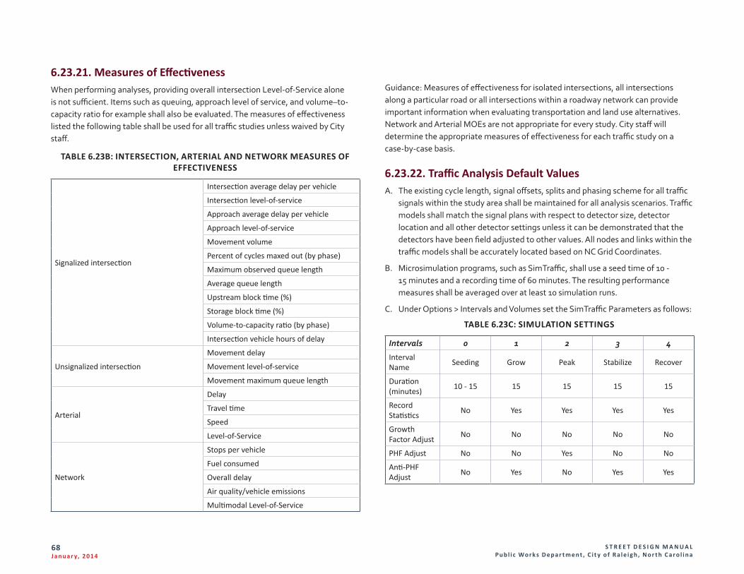
S T R E E T D E S I G N M A N U A L Pu b l i c Wo r k s D e p a r t m e n t , C i t y o f R a l e i g h , N o r t h C a r o l i n a
68J a n u a r y, 2 014
6.23.21. Measures of EffectivenessWhen performing analyses, providing overall intersection Level-of-Service alone is not sufficient. Items such as queuing, approach level of service, and volume–to-capacity ratio for example shall also be evaluated. The measures of effectiveness listed the following table shall be used for all traffic studies unless waived by City staff.
TABLE 6.23B: INTERSECTION, ARTERIAL AND NETWORK MEASURES OF EFFECTIVENESS
Signalized intersection
Intersection average delay per vehicle
Intersection level-of-service
Approach average delay per vehicle
Approach level-of-service
Movement volume
Percent of cycles maxed out (by phase)
Maximum observed queue length
Average queue length
Upstream block time (%)
Storage block time (%)
Volume-to-capacity ratio (by phase)
Intersection vehicle hours of delay
Unsignalized intersection
Movement delay
Movement level-of-service
Movement maximum queue length
Arterial
Delay
Travel time
Speed
Level-of-Service
Network
Stops per vehicle
Fuel consumed
Overall delay
Air quality/vehicle emissions
Multimodal Level-of-Service
Guidance: Measures of effectiveness for isolated intersections, all intersections along a particular road or all intersections within a roadway network can provide important information when evaluating transportation and land use alternatives. Network and Arterial MOEs are not appropriate for every study. City staff will determine the appropriate measures of effectiveness for each traffic study on a case-by-case basis.
6.23.22. Traffic Analysis Default Values A. The existing cycle length, signal offsets, splits and phasing scheme for all traffic
signals within the study area shall be maintained for all analysis scenarios. Traffic models shall match the signal plans with respect to detector size, detector location and all other detector settings unless it can be demonstrated that the detectors have been field adjusted to other values. All nodes and links within the traffic models shall be accurately located based on NC Grid Coordinates.
B. Microsimulation programs, such as SimTraffic, shall use a seed time of 10 - 15 minutes and a recording time of 60 minutes. The resulting performance measures shall be averaged over at least 10 simulation runs.
C. Under Options > Intervals and Volumes set the SimTraffic Parameters as follows:
TABLE 6.23C: SIMULATION SETTINGS
Intervals 0 1 2 3 4
Interval Name Seeding Grow Peak Stabilize Recover
Duration (minutes) 10 - 15 15 15 15 15
Record Statistics No Yes Yes Yes Yes
Growth Factor Adjust No No No No No
PHF Adjust No No Yes No No
Anti-PHF Adjust No Yes No Yes Yes
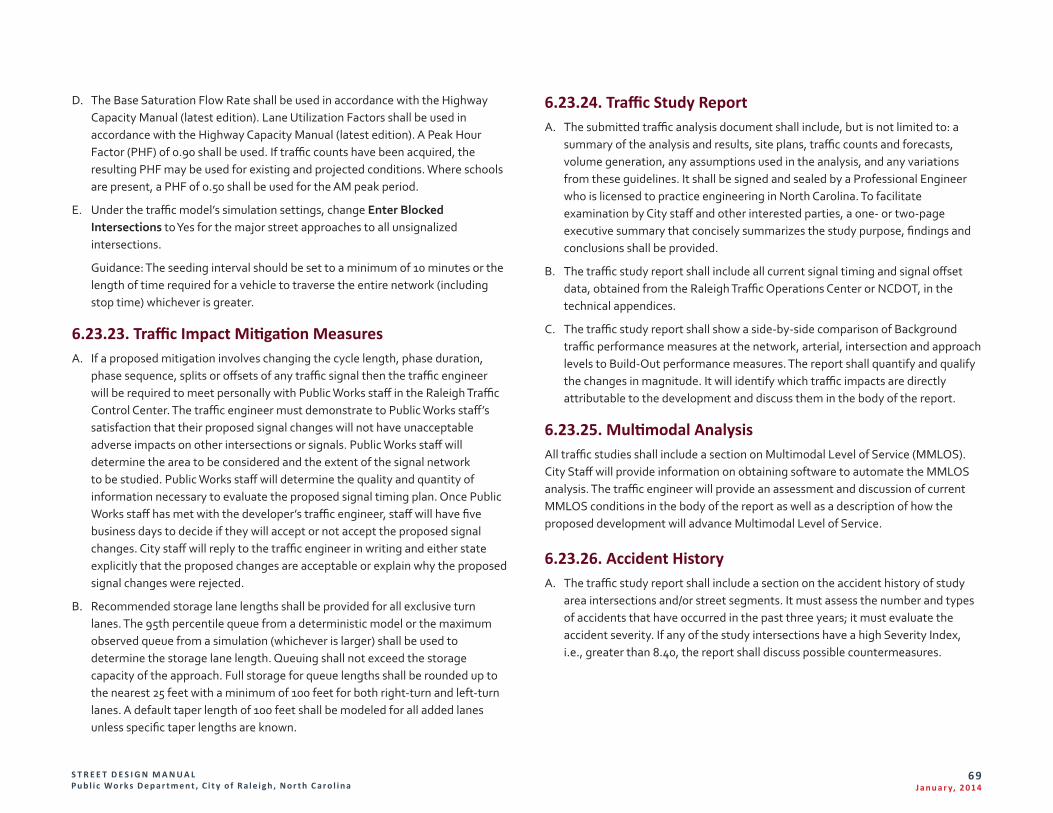
S T R E E T D E S I G N M A N U A L Pu b l i c Wo r k s D e p a r t m e n t , C i t y o f R a l e i g h , N o r t h C a r o l i n a
69J a n u a r y, 2 014
D. The Base Saturation Flow Rate shall be used in accordance with the Highway Capacity Manual (latest edition). Lane Utilization Factors shall be used in accordance with the Highway Capacity Manual (latest edition). A Peak Hour Factor (PHF) of 0.90 shall be used. If traffic counts have been acquired, the resulting PHF may be used for existing and projected conditions. Where schools are present, a PHF of 0.50 shall be used for the AM peak period.
E. Under the traffic model’s simulation settings, change Enter Blocked Intersections to Yes for the major street approaches to all unsignalized intersections.
Guidance: The seeding interval should be set to a minimum of 10 minutes or the length of time required for a vehicle to traverse the entire network (including stop time) whichever is greater.
6.23.23. Traffic Impact Mitigation Measures A. If a proposed mitigation involves changing the cycle length, phase duration,
phase sequence, splits or offsets of any traffic signal then the traffic engineer will be required to meet personally with Public Works staff in the Raleigh Traffic Control Center. The traffic engineer must demonstrate to Public Works staff’s satisfaction that their proposed signal changes will not have unacceptable adverse impacts on other intersections or signals. Public Works staff will determine the area to be considered and the extent of the signal network to be studied. Public Works staff will determine the quality and quantity of information necessary to evaluate the proposed signal timing plan. Once Public Works staff has met with the developer’s traffic engineer, staff will have five business days to decide if they will accept or not accept the proposed signal changes. City staff will reply to the traffic engineer in writing and either state explicitly that the proposed changes are acceptable or explain why the proposed signal changes were rejected.
B. Recommended storage lane lengths shall be provided for all exclusive turn lanes. The 95th percentile queue from a deterministic model or the maximum observed queue from a simulation (whichever is larger) shall be used to determine the storage lane length. Queuing shall not exceed the storage capacity of the approach. Full storage for queue lengths shall be rounded up to the nearest 25 feet with a minimum of 100 feet for both right-turn and left-turn lanes. A default taper length of 100 feet shall be modeled for all added lanes unless specific taper lengths are known.
6.23.24. Traffic Study Report A. The submitted traffic analysis document shall include, but is not limited to: a
summary of the analysis and results, site plans, traffic counts and forecasts, volume generation, any assumptions used in the analysis, and any variations from these guidelines. It shall be signed and sealed by a Professional Engineer who is licensed to practice engineering in North Carolina. To facilitate examination by City staff and other interested parties, a one- or two-page executive summary that concisely summarizes the study purpose, findings and conclusions shall be provided.
B. The traffic study report shall include all current signal timing and signal offset data, obtained from the Raleigh Traffic Operations Center or NCDOT, in the technical appendices.
C. The traffic study report shall show a side-by-side comparison of Background traffic performance measures at the network, arterial, intersection and approach levels to Build-Out performance measures. The report shall quantify and qualify the changes in magnitude. It will identify which traffic impacts are directly attributable to the development and discuss them in the body of the report.
6.23.25. Multimodal Analysis All traffic studies shall include a section on Multimodal Level of Service (MMLOS). City Staff will provide information on obtaining software to automate the MMLOS analysis. The traffic engineer will provide an assessment and discussion of current MMLOS conditions in the body of the report as well as a description of how the proposed development will advance Multimodal Level of Service.
6.23.26. Accident History A. The traffic study report shall include a section on the accident history of study
area intersections and/or street segments. It must assess the number and types of accidents that have occurred in the past three years; it must evaluate the accident severity. If any of the study intersections have a high Severity Index, i.e., greater than 8.40, the report shall discuss possible countermeasures.
S T R E E T D E S I G N M A N U A L Pu b l i c Wo r k s D e p a r t m e n t , C i t y o f R a l e i g h , N o r t h C a r o l i n a
70J a n u a r y, 2 014
B. The North Carolina Department of Transportation maintains a database of all reported accidents that occur within the state. NCDOT has developed special software known as TEAAS (Traffic Engineering Accident Analysis Software) to analyze and report on crashes that occur on roadway segments. TEAAS reports shall be included in the technical appendices. City staff will assist the traffic engineer in obtaining TEAAS reports from NCDOT.
6.23.27. Traffic Study Conclusion and Recommendations A. The traffic study report is to be an objective, technical analysis. All conclusions
and recommendations shall be based solely on information contained within the report; all findings shall be clearly documented. It is acceptable to cite publications within the public realm such as the Manual on Uniform Traffic Control Devices, the AASHTO Highway Safety Manual, Federal Highway Administration reports, etc. in order to provide supporting evidence or to articulate key points provided that the citation includes the title, section/chapter and page number of the reference source.
B. The analyses shall be presented in a straightforward and logical sequence. The analyses shall lead the reader step-by-step through the various stages of the process to the resulting conclusion and recommendations. Sufficient detail shall be included so that City staff will be able to follow the rationale and methodology of the analysis.
C. Whenever possible, data should be presented in tables, graphs, maps and diagrams rather than narrative text. When appropriate, schematics drawings of roadway improvements, such as intersection reconfigurations, may be included and described in the text. Since the report may be read by nontechnical decision-makers and interested citizens, it should be as concise as possible with a minimum of jargon.
D. Recommendations where mitigation or improvements are identified “by others” shall clarify which parties are to provide the additional improvements. The traffic study report shall provide documentation that those parties have agreed to construct the additional improvements. The study shall not use planned, but unfunded improvements, by government agencies as a means of mitigation.
E. The traffic study report shall not include political views or statements, nor shall it take an advocacy position.
Guidance: City staff reserves the right to impose additional conditions and to ask for additional information during the course of the review if warranted by obvious concerns over possible traffic impacts on adjacent properties, roads or intersections. Inadequate reports will be returned to the traffic engineer for completion or modification. In such cases, City staff will state in writing the report’s deficiencies and will provide direction for addressing those deficiencies.
6.23.28. Traffic Study Submittal Requirements A. Submit all traffic model data files, a pdf file of the traffic study report [including
appendices] and two bound copies of the traffic study report directly to:
City of Raleigh, Office of Transportation Planning One Exchange Plaza, Suite 727 Raleigh, NC 27601
B. City staff will acknowledge receipt of the report via email within 24 hours. Until acknowledged by City staff, the report has not been officially received.
Guidance: Staff’s preference is that one hard copy contains the body of the report and the second hard copy contains both the body and the technical appendix.
6.24. Bicycle Infrastructure 6.24.1. Bike Parking Standards A. Standard U-Rack Design Detail
1. Distance to other Racks:
a. Racks aligned parallel to each other (side by side) must be at least 36 inches (3ft) apart.
b. Rack units aligned end to end must be at least 96 inches (8ft) apart.
2. Distance from a Curb:
a. Rack units placed perpendicular to the curb must be at least 48 inches (4ft) from the curb to the nearest vertical component of the rack.
b. Rack units placed parallel to the curb must be at least 24 (2ft) inches from the curb.
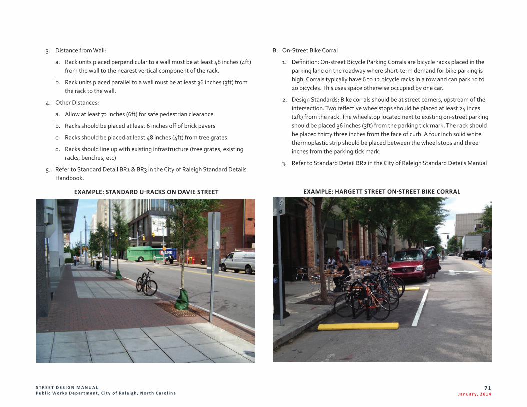
S T R E E T D E S I G N M A N U A L Pu b l i c Wo r k s D e p a r t m e n t , C i t y o f R a l e i g h , N o r t h C a r o l i n a
71J a n u a r y, 2 014
3. Distance from Wall:
a. Rack units placed perpendicular to a wall must be at least 48 inches (4ft) from the wall to the nearest vertical component of the rack.
b. Rack units placed parallel to a wall must be at least 36 inches (3ft) from the rack to the wall.
4. Other Distances:
a. Allow at least 72 inches (6ft) for safe pedestrian clearance
b. Racks should be placed at least 6 inches off of brick pavers
c. Racks should be placed at least 48 inches (4ft) from tree grates
d. Racks should line up with existing infrastructure (tree grates, existing racks, benches, etc)
5. Refer to Standard Detail BR1 & BR3 in the City of Raleigh Standard Details Handbook.
EXAMPLE: STANDARD U-RACKS ON DAVIE STREET
B. On-Street Bike Corral
1. Definition: On-street Bicycle Parking Corrals are bicycle racks placed in the parking lane on the roadway where short-term demand for bike parking is high. Corrals typically have 6 to 12 bicycle racks in a row and can park 10 to 20 bicycles. This uses space otherwise occupied by one car.
2. Design Standards: Bike corrals should be at street corners, upstream of the intersection. Two reflective wheelstops should be placed at least 24 inces (2ft) from the rack. The wheelstop located next to existing on-street parking should be placed 36 inches (3ft) from the parking tick mark. The rack should be placed thirty three inches from the face of curb. A four inch solid white thermoplastic strip should be placed between the wheel stops and three inches from the parking tick mark.
3. Refer to Standard Detail BR2 in the City of Raleigh Standard Details Manual
EXAMPLE: HARGETT STREET ON-STREET BIKE CORRAL
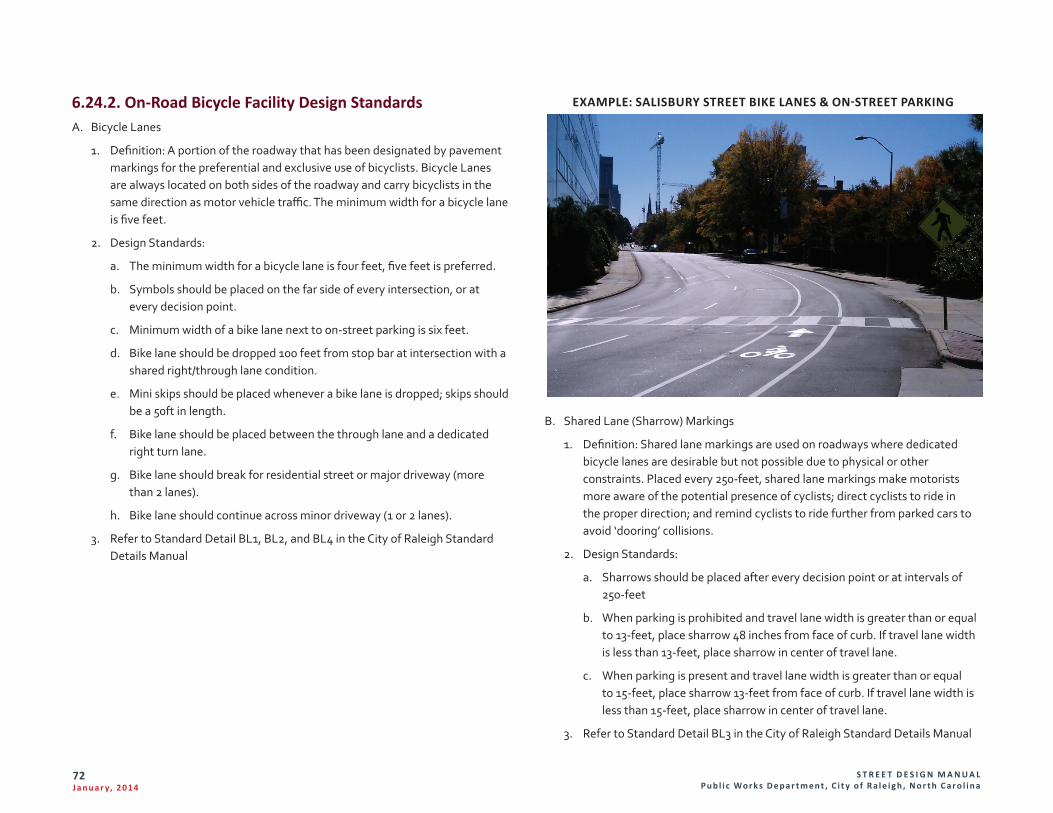
S T R E E T D E S I G N M A N U A L Pu b l i c Wo r k s D e p a r t m e n t , C i t y o f R a l e i g h , N o r t h C a r o l i n a
72J a n u a r y, 2 014
6.24.2. On-Road Bicycle Facility Design Standards A. Bicycle Lanes
1. Definition: A portion of the roadway that has been designated by pavement markings for the preferential and exclusive use of bicyclists. Bicycle Lanes are always located on both sides of the roadway and carry bicyclists in the same direction as motor vehicle traffic. The minimum width for a bicycle lane is five feet.
2. Design Standards:
a. The minimum width for a bicycle lane is four feet, five feet is preferred.
b. Symbols should be placed on the far side of every intersection, or at every decision point.
c. Minimum width of a bike lane next to on-street parking is six feet.
d. Bike lane should be dropped 100 feet from stop bar at intersection with a shared right/through lane condition.
e. Mini skips should be placed whenever a bike lane is dropped; skips should be a 50ft in length.
f. Bike lane should be placed between the through lane and a dedicated right turn lane.
g. Bike lane should break for residential street or major driveway (more than 2 lanes).
h. Bike lane should continue across minor driveway (1 or 2 lanes).
3. Refer to Standard Detail BL1, BL2, and BL4 in the City of Raleigh Standard Details Manual
EXAMPLE: SALISBURY STREET BIKE LANES & ON-STREET PARKING
B. Shared Lane (Sharrow) Markings
1. Definition: Shared lane markings are used on roadways where dedicated bicycle lanes are desirable but not possible due to physical or other constraints. Placed every 250-feet, shared lane markings make motorists more aware of the potential presence of cyclists; direct cyclists to ride in the proper direction; and remind cyclists to ride further from parked cars to avoid ‘dooring’ collisions.
2. Design Standards:
a. Sharrows should be placed after every decision point or at intervals of 250-feet
b. When parking is prohibited and travel lane width is greater than or equal to 13-feet, place sharrow 48 inches from face of curb. If travel lane width is less than 13-feet, place sharrow in center of travel lane.
c. When parking is present and travel lane width is greater than or equal to 15-feet, place sharrow 13-feet from face of curb. If travel lane width is less than 15-feet, place sharrow in center of travel lane.
3. Refer to Standard Detail BL3 in the City of Raleigh Standard Details Manual
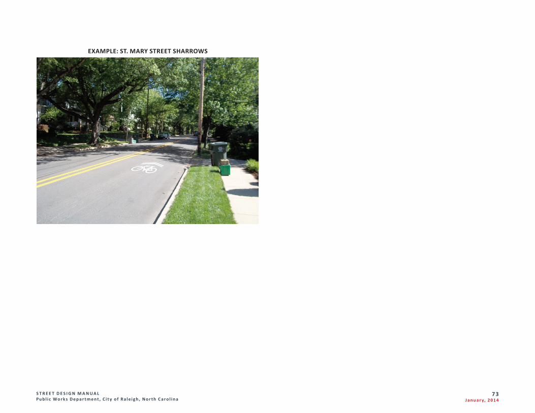
S T R E E T D E S I G N M A N U A L Pu b l i c Wo r k s D e p a r t m e n t , C i t y o f R a l e i g h , N o r t h C a r o l i n a
73J a n u a r y, 2 014
EXAMPLE: ST. MARY STREET SHARROWS
S T R E E T D E S I G N M A N U A L Pu b l i c Wo r k s D e p a r t m e n t , C i t y o f R a l e i g h , N o r t h C a r o l i n a
74J a n u a r y, 2 014
Section 7. Glossary 7.1. Defined TermsAASHTO. The American Association of State Highway Transportation Officials.
Access Point. A point of ingress and/or egress, which connects a development to a public or private street.
Approach. The portion of an intersection leg which is used by traffic approaching the intersection.
Bicycle Lanes. A portion of the roadway that has been designated by pavement markings for the preferential and exclusive use of bicyclists. Bicycle Lanes are always located on both sides of the roadway and carry bicyclists in the same direction as motor vehicle traffic. The minimum width for a bicycle lane is five feet.
Capacity. The maximum sustainable hourly rate at which persons or vehicles can reasonably be expected to traverse a point or uniform segment of a lane or roadway during a given time period under prevailing traffic, roadway and control conditions.
City. The City of Raleigh, North Carolina.
City Code. The Charter and Code of Ordinances of the City of Raleigh, North Carolina.
City Council. The governing body for the City of Raleigh, North Carolina.
City Standards and Specifications. Those standards prescribed for the construction of streets, sidewalks, driveway access points, curb and gutter set out in this manual and the City Code.
Commercial Driveway Access. Any driveway access point that does not meet the definition of residential driveway access.
Comprehensive Plan. The “Raleigh Comprehensive Plan” was adopted by the City Council as a guide for the development of the City and territory surrounding the City, consisting of maps, charts and text.
Connective Street. A street within a development, other than a cul-de-sac street or loop street, which will allow vehicular and pedestrian circulation to adjoining developments; thereby providing for community-wide circulation.
Coordination (signal). Maintaining a predictable time relationship between the operation of a traffic signal relative to the operation of other signals in a group or system.
Cycle. A complete sequence of traffic signal indications.
Cycle Length. The time elapsed between the endings of two sequential terminations of a given interval. For coordinated signals, this is measured by using the coordinated phase green interval.
Design Speed. Usually up to five miles per hour above the expected operating speed of the facility under design.
Design Vehicle. Motor and non-motor vehicles with representative weight, dimensions, and operating characteristics that are used to establish stree design controls and standards. Five general classes of design vehicles have been stablished: (1) passenger cars, (2) buses, (3) trucks, (4) recreational vehicles, and (5) bycicles. The truck class includes single-unit trucks, truck tractor-semitrailer combinations, and truck tractors with semitrailers in combination with full trailers.
Development or Development Plan. Any site plan, subdivision, or plot plan
Detector. A device used to sense the presence or absence of vehicles or pedestrians in the vicinity of a signalized intersection.
Detector Settings. Controls used to affect the operation of a detector.
Developer. A site planner, landowner or subdivider.
Development/Development Plan. Any site plan or subdivision plan.
Driveway Access Point. A point of ingress and egress, or both, which is considered a private driveway. It can be either a residential access point or a commercial driveway access point.
Driveway Width. The narrowest width of driveway measured parallel with the edge of street.
S T R E E T D E S I G N M A N U A L Pu b l i c Wo r k s D e p a r t m e n t , C i t y o f R a l e i g h , N o r t h C a r o l i n a
75J a n u a r y, 2 014
Frontage. The shy distance (additional sidewalk or shoulder width) required between the pedestrian traveler and adjacent building or environmental features to maintain comfort.
Green Interval. The duration of the green indication for a given movement at a signalized intersection.
Internal Capture Trip. A trip made within the confines of a mixed use development that does not use the off-site street system.
ITE. The Institute of Transportation Engineers
Level-of-Service (LOS). A quantitative stratification of a performance measure or measures that represent quality of service, measured on an A – F scale, with LOS A representing the best operating conditions from the traveler’s perspective and LOS F the worst.
LID. Low Impact development
Loop Street. A street which is designed to discourage through traffic from other areas and both ends of the loop street connect with the same intersecting street.
Measures of effectiveness (MOEs). Are measureable quantities and characteristics used to compare traffic impacts from various alternatives. Measures of effectiveness quantify traffic impacts and allow for an objective examination of the results. Traffic impacts can be quantified in a variety of ways such as delay, queuing or average speed and at different scales. In many instances, the specific quantity for a given MOE is not as significant as the relative change of in MOE quantity between different alternatives. “Scale” refers to impacts for a specific area under review: an isolated intersection, all intersections along a particular road or all intersections within a roadway network.
Median. That portion of a divided roadway separating the traveled ways for traffic in opposite directions.
Mitigation. Alleviation, reduction, abatement or diminution of traffic impacts created by a development.
Mixed Use Development. A single real estate project that consists of two or more land use classifications between which trips can be made without using the off-site street system.
Multimodal. Being used by more than one travel mode such as motor vehicles, pedestrians and bicycles.
Multimodal Level-of-Service (MMLOS). A type of analysis where the level-of-service of each travel mode on a facility is evaluated simultaneously.
NCDOT. The North Carolina Department of Transportation
Offset. The time that the reference phase of a traffic signal begins (or ends) relative to the system master time zero.
On-Street Bike Corral. On-street Bicycle Parking Corrals are bicycle racks placed in the parking lan on the roadway where short-term demand for bike parking is high. Corrals typically have 6 to 12 bicycle racks in a row and can park 10 to 20 bicycles. This uses space otherwise occupied by one car.
Pass-by Trip. A trip made as an intermediate stop from an origin to a destination that does not require a route diversion.
Phase (signal). The part of the signal cycle allocated to any combination of traffic movements receiving the right-of-way simultaneously during one or more intervals. A phase includes the green, yellow change, and red clearance intervals.
Phase Sequence. (1) The sequence of service provided to each traffic movement. (2) A description of the order in which left-turn movements are served relative to the through movements.
Phase Settings. Controls used to influence the start, duration and ending of a signal phase.
Primary Trip. A trip made for the specific purpose of visiting a destination. Stopping at the destination is the primary reason for the trip.
Pavement Markings. All lines, words or symbols, except signs officially placed within the roadway or parking area to regulate, warn or guide traffic.
Peak-Hour Volume. Hourly traffic volume used for roadway design and capacity analysis, usually occurring during one or more peak travel hours during a 24 hour period.
Public Works Director. The Department Head of the City of Raleigh Public Works Department.
S T R E E T D E S I G N M A N U A L Pu b l i c Wo r k s D e p a r t m e n t , C i t y o f R a l e i g h , N o r t h C a r o l i n a
76J a n u a r y, 2 014
Reference Phase. One of the two coordinated phases of a traffic signal.
Residential Driveway Access. A driveway access point serving a single family dwelling, mobile home, detached townhouse, two attached townhouses, duplex, multi-unit supportive housing residence, supportive housing residence which is required to provide no more than two (2) off-street parking spaces, or a driveway serving a nonresidential use if the daily volume of two-way driveway traffic is expected to be less than fifty (50) vehicles.
Right-of-Way. An interest in land to the City which provides for the perpetual right and privilege of the City and its agents, franchise holders, successors, and assigns to construct, install, improve, repair, maintain, and use a public street, including related and customary uses of street rights-of-way such as sidewalk, bike path, landscaping, traffic control devices and signage, sanitary sewer, stormwater drainage devices, water supply, cable television, electric power, gas, and telephone transmission and related purposes in, upon, over, below, and across the rights of- way. The City is authorized to remove,and keep removed from the rights-of-way all trees, vegetation, and other obstructions as is determined to be necessary by the City to maintain, repair, and protect facilities located in the right-of-way
Right-of-Way Centerline
1) The right-of-way centerline of a two-way street shall be a point equidistant between the inside edges of the innermost through travel lane in each direction of travel.
2) The right-of-way centerline of a one-way street shall be a point equidistant between the outside edges of the outermost through travel lanes in the direction of travel.
3) Where the alignment of an existing street is to be altered or changed, the right-of-way centerline shall be determined in accordance with the new realignment plan, provided the City and/or NCDOT have approved the plan.
4) In special cases where non-symmetrical street widening has occurred or other unique situations not covered by the above exist, the right-of-way centerline shall be defined by the Public Works Director.
Roadway. See definition of street.
Roundabout. An unsignalized intersection with a generally circular shape, characterized by yield on entry and circulation around a central island.
Shall. When used in the context of this Manual and its contents, shall indicates a mandatory action, procedure or practice.
Shared Lane (Sharrow) Markings. Shared lane markings are used on roadways where dedicated bicycle lanes are desirable but not possible due to physical or other constraints. Placed every 250-feet, shared lane markings make motorists more aware of the potential presence of cyclists; direct cyclists to ride in the proper direction; and remind cyclists to ride further from parked cars to avoid ‘dooring’ collisions.
Shopping Center. A planned, unified development which contains at least three (3) retail or recreational establishments within a minimum of twenty-five thousand (25,000) square feet of floor area gross on a land area of at least two and one-half (2.5) areas in size.
Should. As used in the context of traffic studies, should indicates a mandatory action, procedure or practice that City staff is empowered to waive.
Slope Easement. An easement, which is reasonably necessary and incidental to the construction within the adjoining right-of-way of public street or sidewalk, or both, by the City, state, or their contractors. The purposes to which the easement area may be used include cutting, sloping, filling, installation of stormwater drain pipes or other drainage facilities, grading or otherwise changing the natural contour of the easement area in order to support and to accommodate the development of the adjacent street right-of-way, in accord with generally accepted engineering practices. Following the construction of the adjacent street or sidewalk, or both, the area subject to this easement will be graded, stabilized, and restored using conventional engineering and landscaping methods. Thereafter, the landowners with the underlying fee interest may make and enjoy all lawful uses of the property subject to this easement, provided there be no damage to the lateral and subjacent support of the public street, sidewalk, or both or to any stormwater drainage facility.
Split. The segment of the cycle length allocated to each phase or interval that may occur. In an actuated controller unit, split is the time in the cycle allocated to a phase – the sum of the green, yellow change, and red clearance intervals for a phase.
Street. A general term for denoting a public way for purposes of pedestrian, bike
S T R E E T D E S I G N M A N U A L Pu b l i c Wo r k s D e p a r t m e n t , C i t y o f R a l e i g h , N o r t h C a r o l i n a
77J a n u a r y, 2 014
and vehicular travel, including the entire area within the right-of-way.
Street Furniture. Undefined at this time
Traffic Engineer. A professional engineer who is licensed by the North Carolina Board of Examiners for Engineers and Surveyors to practice engineering and who has special knowledge of traffic engineering principles through a combination of education, training and experience.
Traffic Engineering. The application of scientific and mathematical principles to facilitate the safe and efficient movement of people, goods and information.
Traffic Impact. A measurable, quantifiable or qualified effect on one or more traffic performance measures. Traffic impacts can be beneficial or detrimental.
Traffic Performance Measures. Synonymous with Measures of Effectiveness.
Traffic Sign. A device mounted on a fixed or movable support, conveying a message or symbol to regulate, warn or guide traffic.
Traffic Study. A collective term for Trip Generation Reports, Traffic Assessment Report or Traffic Impact Analysis Reports (see below).
1) Trip Generation Report: Calculates the expected number of new trips that a development will generate during the AM and PM peak periods. Trip generation reports are required for all rezoning cases. Exceptions can be made for rezoning cases that do not affect the trip generation characteristics of the property such as tree conservation areas, stormwater retention, location and size of building signs, etc.
2) Traffic Assessment (TA) Report: Calculates the expected number of new trips and calculates the current amount of delay, queuing and traffic capacity available at the nearest intersection(s). If existing delays and volume-to-capacity ratios are low, City staff may conclude that the adjacent roadway network can absorb new trips without becoming congested. In that case, no further study is needed.
3) Traffic Impact Analysis (TIA) Report: Calculates the expected number of new trips and calculates the current amount of delay, queuing and traffic capacity available at the nearest intersections. TIAs calculate the amount of delay, queuing and volume-to-capacity ratio and other variables both before and after a development is built. City staff will then use engineering judgment to determine if the developers should mitigate some of the traffic impacts
from their development by adding a new turn lane or installing some other improvement. If mitigation is recommended, the TIA shall recalculate the traffic impacts after the mitigation measures have been installed. It will quantify those impacts that can be directly attributed to the new development and the effect of any mitigation.
Travelway. The travelway refers to the paved width of a street between curbs accommodates moving and stationary vehicles in a variety of modes.
Trip. Travel between an origin and a destination.
Urban Design Guidelines. A portion of the Guidelines section (Chapter 4) of the Raleigh Comprehensive Plan that describes the elements of Mixed-Use Neighborhood and Village Centers.
Volume. The number of vehicles passing a given point during a specified period of time.

S T R E E T D E S I G N M A N U A L Pu b l i c Wo r k s D e p a r t m e n t , C i t y o f R a l e i g h , N o r t h C a r o l i n a
78J a n u a r y, 2 014
Section 8. Standard Detail Drawings A complete listing of standard detail drawings are available on the web in the following formats: Adobe Acrobat, AutoCAD and MicroStation, click here for full listing.