Embed Size (px)
Citation preview
1
DOCUMENT
Open Competitive Bid (OCB)
For
Supply and Installation of equipments to
Materials Characterization Lab and
Materials Testing and Processing Lab of
Metallurgical & Materials Engineering Dept. at the three campuses of
Rajiv Gandhi University of Knowledge Technologies
Proprietary & Confidential
RAJIV GANDHI UNIVERSITY OF KNOWLEDGE TECHNOLOGIES
Ground Floor, Vindhya C4 Building, IIIT-H Campus, Gachibowli
HYDERABAD- 500 032 Phone: 040-23001830
2
Proprietary & Confidential
No part of this document can be reproduced in any form
or by any means, disclosed or distributed to any person
without the prior consent of RGUKT except to the extent
required for submitting bid and no more.
3
Contents
Description
Page No.
Newspaper advertisement 4
Time Schedule 5
Tender Form 6
Statement of important limits and values of bid 7-8
Eligibility criteria 9-10
Requirement & Technical Specifications 11-30
Note 31
4
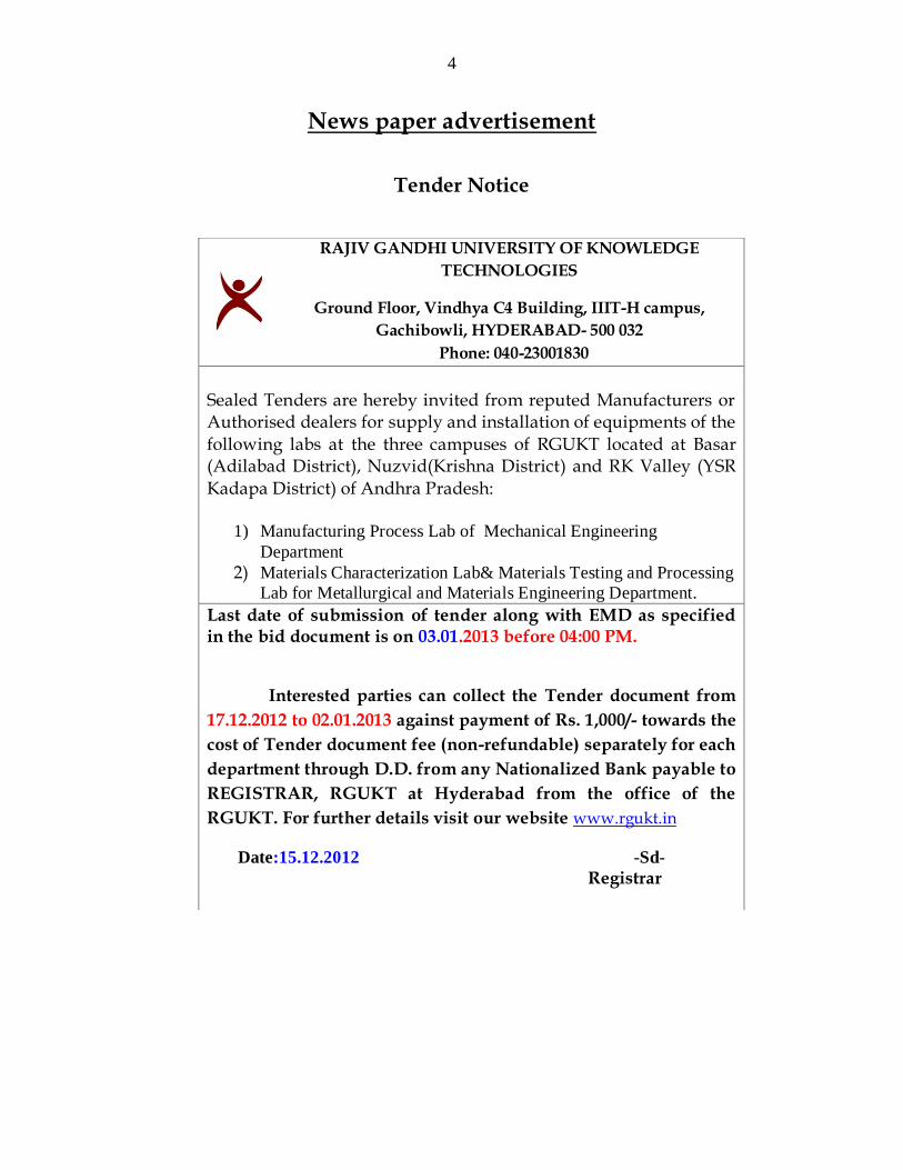
News paper advertisement
Tender Notice
RAJIV GANDHI UNIVERSITY OF KNOWLEDGE
TECHNOLOGIES
Ground Floor, Vindhya C4 Building, IIIT-H campus,
Gachibowli, HYDERABAD- 500 032
Phone: 040-23001830
Sealed Tenders are hereby invited from reputed Manufacturers or Authorised dealers for supply and installation of equipments of the
following labs at the three campuses of RGUKT located at Basar (Adilabad District), Nuzvid(Krishna District) and RK Valley (YSR
Kadapa District) of Andhra Pradesh:
1) Manufacturing Process Lab of Mechanical Engineering
Department
2) Materials Characterization Lab& Materials Testing and Processing
Lab for Metallurgical and Materials Engineering Department.
Last date of submission of tender along with EMD as specified in the bid document is on 03.01.2013 before 04:00 PM.
Interested parties can collect the Tender document from
17.12.2012 to 02.01.2013 against payment of Rs. 1,000/- towards the
cost of Tender document fee (non-refundable) separately for each
department through D.D. from any Nationalized Bank payable to
REGISTRAR, RGUKT at Hyderabad from the office of the
RGUKT. For further details visit our website www.rgukt.in
Date:15.12.2012 -Sd-
Registrar
5
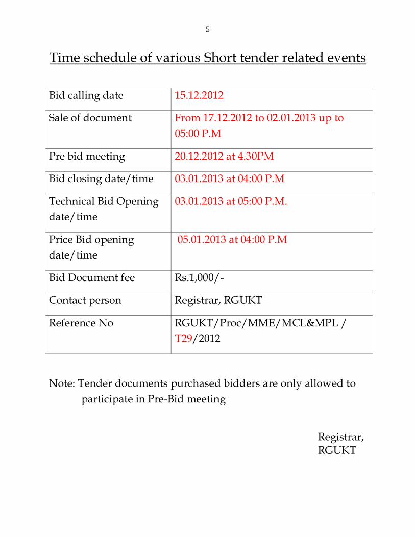
Time schedule of various Short tender related events
Bid calling date 15.12.2012
Sale of document From 17.12.2012 to 02.01.2013 up to
05:00 P.M
Pre bid meeting 20.12.2012 at 4.30PM
Bid closing date/time 03.01.2013 at 04:00 P.M
Technical Bid Opening
date/time
03.01.2013 at 05:00 P.M.
Price Bid opening
date/time
05.01.2013 at 04:00 P.M
Bid Document fee Rs.1,000/-
Contact person Registrar, RGUKT
Reference No RGUKT/Proc/MME/MCL&MPL /
T29/2012
Note: Tender documents purchased bidders are only allowed to
participate in Pre-Bid meeting
Registrar, RGUKT
6
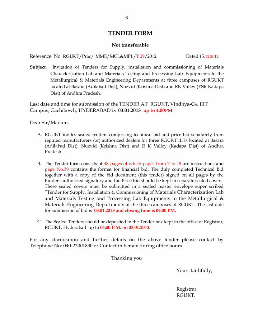
TENDER FORM
Not transferable
Reference. No. RGUKT/Proc/ MME/MCL&MPL/T 29/2012 Dated 15.12.2012
Subject: Invitation of Tenders for Supply, installation and commissioning of Materials
Characterization Lab and Materials Testing and Processing Lab Equipments to the
Metallurgical & Materials Engineering Departments at three campuses of RGUKT
located at Basara (Adilabad Dist), Nuzvid (Krishna Dist) and RK Valley (YSR Kadapa
Dist) of Andhra Pradesh.
Last date and time for submission of the TENDER AT RGUKT, Vindhya-C4, IIIT
Campus, Gachibowli, HYDERABAD is 03.01.2013 up to 4:00PM
Dear Sir/Madam,
A. RGUKT invites sealed tenders comprising technical bid and price bid separately from
reputed manufacturers (or) authorized dealers for three RGUKT IIITs located at Basara (Adilabad Dist), Nuzvid (Krishna Dist) and R K Valley (Kadapa Dist) of Andhra Pradesh.
B. The Tender form consists of 48 pages of which pages from 7 to 18 are instructions and
page No.39 contains the format for financial bid. The duly completed Technical Bid together with a copy of the bid document (this tender) signed on all pages by the Bidders authorized signatory and the Price Bid should be kept in separate sealed covers. These sealed covers must be submitted in a sealed master envelope super scribed
“Tender for Supply, Installation & Commissioning of Materials Characterization Lab
and Materials Testing and Processing Lab Equipments to the Metallurgical & Materials Engineering Departments at the three campuses of RGUKT. The last date for submission of bid is 03.01.2013 and closing time is 04:00 PM.
C. The Sealed Tenders should be deposited in the Tender box kept in the office of Registrar, RGUKT, Hyderabad up to 04:00 P.M. on 03.01.2013.
For any clarification and further details on the above tender please contact by Telephone No: 040-23001830 or Contact in Person during office hours.
Thanking you
Yours faithfully,
Registrar,
RGUKT.
7
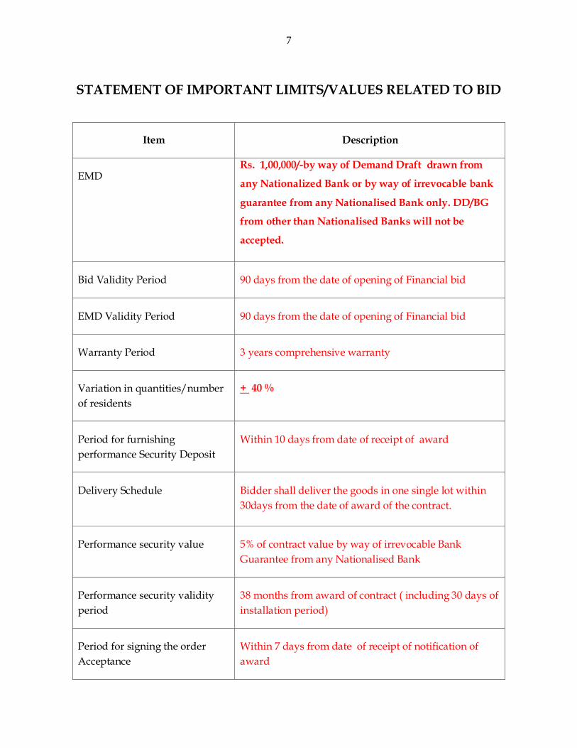
STATEMENT OF IMPORTANT LIMITS/VALUES RELATED TO BID
Item Description
EMD Rs. 1,00,000/-by way of Demand Draft drawn from
any Nationalized Bank or by way of irrevocable bank
guarantee from any Nationalised Bank only. DD/BG
from other than Nationalised Banks will not be
accepted.
Bid Validity Period 90 days from the date of opening of Financial bid
EMD Validity Period 90 days from the date of opening of Financial bid
Warranty Period 3 years comprehensive warranty
Variation in quantities/number
of residents
+ 40 %
Period for furnishing
performance Security Deposit
Within 10 days from date of receipt of award
Delivery Schedule Bidder shall deliver the goods in one single lot within
30days from the date of award of the contract.
Performance security value 5% of contract value by way of irrevocable Bank
Guarantee from any Nationalised Bank
Performance security validity
period
38 months from award of contract ( including 30 days of
installation period)
Period for signing the order
Acceptance
Within 7 days from date of receipt of notification of
award
8
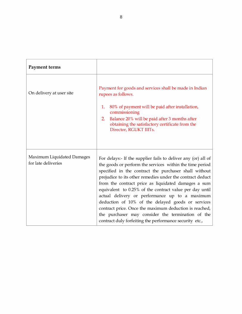
Payment terms
On delivery at user site
Payment for goods and services shall be made in Indian
rupees as follows.
1. 80% of payment will be paid after installation, commissioning
2. Balance 20% will be paid after 3 months after obtaining the satisfactory certificate from the Director, RGUKT IIITs.
Maximum Liquidated Damages
for late deliveries
For delays:- If the supplier fails to deliver any (or) all of
the goods or perform the services within the time period
specified in the contract the purchaser shall without
prejudice to its other remedies under the contract deduct
from the contract price as liquidated damages a sum
equivalent to 0.25% of the contract value per day until
actual delivery or performance up to a maximum
deduction of 10% of the delayed goods or services
contract price. Once the maximum deduction is reached,
the purchaser may consider the termination of the
contract duly forfeiting the performance security etc.,
9
ELIGIBILITY CRITERIA
5.1. This bid is open to all firms within India who are eligible to do business under
relevant Indian laws as in force at the time of bidding, subject to meeting the pre-
qualification criterion. They should provide list of customers of previous supply of
similar/ same items to IITs, NIT’s or Central Universities or any Academic Institute
of National repute with contact details. Copies of orders received from the reputed
firms on bidding firm need to be submitted.
5.2. The bidder should have servicing facility or work shop with in India so the
provision of service is possible at a short notice and without incurrence of delay.
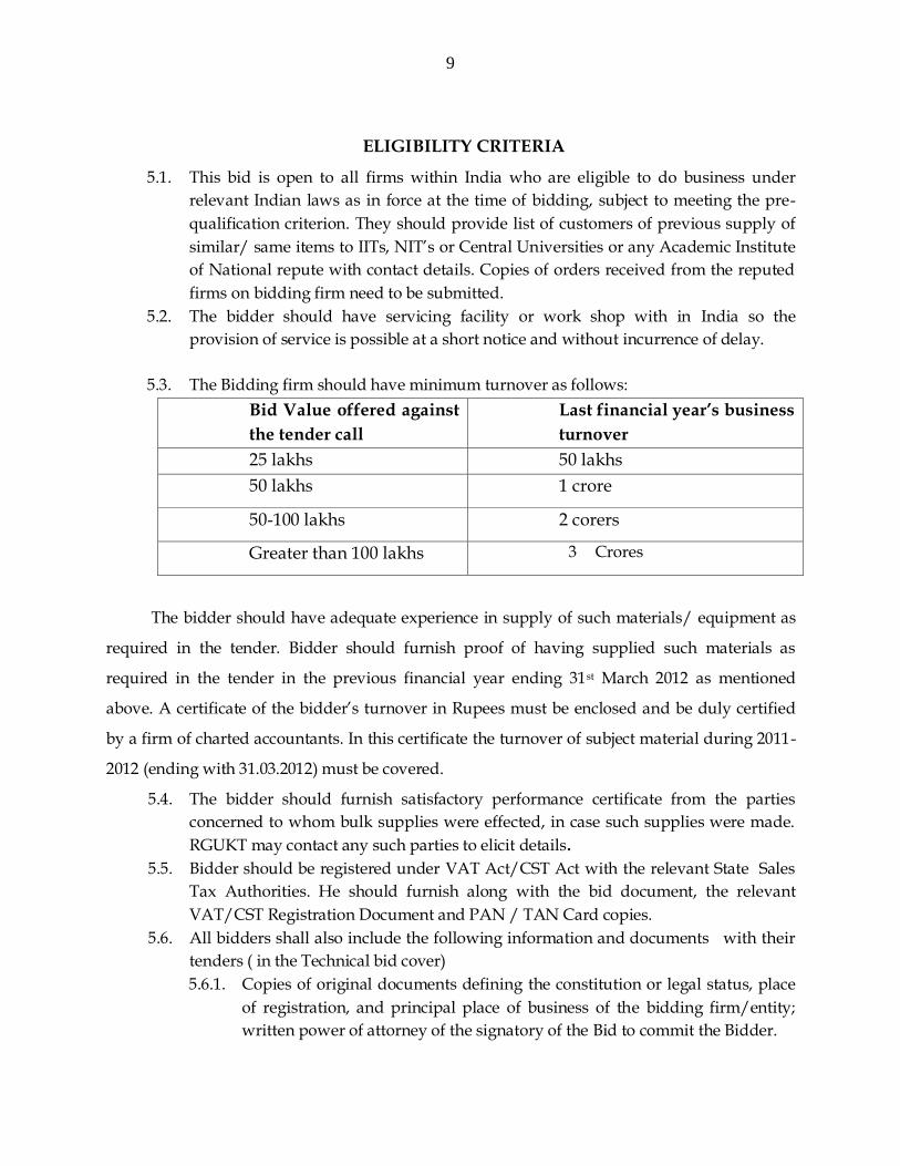
5.3. The Bidding firm should have minimum turnover as follows:
Bid Value offered against
the tender call
Last financial year’s business
turnover
25 lakhs 50 lakhs
50 lakhs 1 crore
50-100 lakhs 2 corers
Greater than 100 lakhs 3 Crores
The bidder should have adequate experience in supply of such materials/ equipment as
required in the tender. Bidder should furnish proof of having supplied such materials as
required in the tender in the previous financial year ending 31st March 2012 as mentioned
above. A certificate of the bidder’s turnover in Rupees must be enclosed and be duly certified
by a firm of charted accountants. In this certificate the turnover of subject material during 2011-
2012 (ending with 31.03.2012) must be covered.
5.4. The bidder should furnish satisfactory performance certificate from the parties
concerned to whom bulk supplies were effected, in case such supplies were made.
RGUKT may contact any such parties to elicit details.
5.5. Bidder should be registered under VAT Act/CST Act with the relevant State Sales
Tax Authorities. He should furnish along with the bid document, the relevant
VAT/CST Registration Document and PAN / TAN Card copies.
5.6. All bidders shall also include the following information and documents with their
tenders ( in the Technical bid cover)
5.6.1. Copies of original documents defining the constitution or legal status, place
of registration, and principal place of business of the bidding firm/entity;
written power of attorney of the signatory of the Bid to commit the Bidder.

10
5.6.2. Machinery/equipment owned by the bidder and number of employees.
5.6.3. Latest Income Tax returns and VAT/ CST Returns filed.
5.6.4. List of Present Clientele with contact addresses & telephone numbers.
5.7. All the certificates furnished along with technical bids should be attested by a
Gazetted Officer, counter signed by bidder along with their seal.
The bidders must submit all relevant documentary evidence in support to
their claim for eligibility in placing bid. The tenders received without the
above documents will be rejected.
11
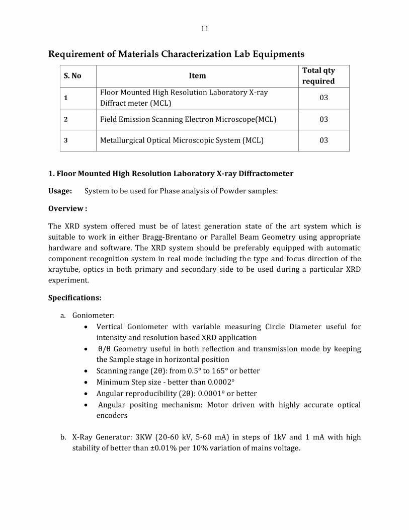
Requirement of Materials Characterization Lab Equipments
S. No Item Total qty
required
1 Floor Mounted High Resolution Laboratory X-ray
Diffract meter (MCL) 03
2 Field Emission Scanning Electron Microscope(MCL) 03
3 Metallurgical Optical Microscopic System (MCL) 03
1. Floor Mounted High Resolution Laboratory X-ray Diffractometer
Usage: System to be used for Phase analysis of Powder samples:
Overview :
The XRD system offered must be of latest generation state of the art system which is
suitable to work in either Bragg-Brentano or Parallel Beam Geometry using appropriate
hardware and software. The XRD system should be preferably equipped with automatic
component recognition system in real mode including the type and focus direction of the
xraytube, optics in both primary and secondary side to be used during a particular XRD
experiment.
Specifications:
a. Goniometer:
Vertical Goniometer with variable measuring Circle Diameter useful for
intensity and resolution based XRD application
θ/θ Geometry useful in both reflection and transmission mode by keeping
the Sample stage in horizontal position
Scanning range (2θ): from 0.5° to 165° or better
Minimum Step size - better than 0.0002°
Angular reproducibility (2θ): 0.0001º or better
Angular positing mechanism: Motor driven with highly accurate optical
encoders
b. X-Ray Generator: 3KW (20-60 kV, 5-60 mA) in steps of 1kV and 1 mA with high
stability of better than ±0.01% per 10% variation of mains voltage.
12
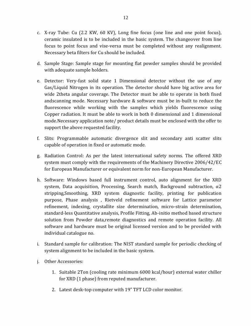
c. X-ray Tube: Cu (2.2 KW, 60 KV), Long fine focus (one line and one point focus),
ceramic insulated is to be included in the basic system. The changeover from line
focus to point focus and vise-versa must be completed without any realignment.
Necessary beta filters for Cu should be included.
d. Sample Stage: Sample stage for mounting flat powder samples should be provided
with adequate sample holders.
e. Detector: Very-fast solid state 1 Dimensional detector without the use of any
Gas/Liquid Nitrogen in its operation. The detector should have big active area for
wide 2theta angular coverage. The Detector must be able to operate in both fixed
andscanning mode. Necessary hardware & software must be in-built to reduce the
fluorescence while working with the samples which yields fluorescence using
Copper radiation. It must be able to work in both 0 dimensional and 1 dimensional
mode.Necessary application note/ product details must be enclosed with the offer to
support the above requested facility.
f. Slits: Programmable automatic divergence slit and secondary anti scatter slits
capable of operation in fixed or automatic mode.
g. Radiation Control: As per the latest international safety norms. The offered XRD
system must comply with the requirements of the Machinery Directive 2006/42/EC
for European Manufacturer or equivalent norm for non-European Manufacturer.
h. Software: Windows based full instrument control, auto alignment for the XRD
system, Data acquisition, Processing, Search match, Background subtraction, α2
stripping,Smoothing, XRD system diagnostic facility, printing for publication
purpose, Phase analysis , Rietveld refinement software for Lattice parameter
refinement, indexing, crystallite size determination, micro-strain determination,
standard-less Quantitative analysis, Profile Fitting, Ab-initio method based structure
solution from Powder data,remote diagnostics and remote operation facility. All
software and hardware must be original licensed version and to be provided with
individual catalogue no.
i. Standard sample for calibration: The NIST standard sample for periodic checking of
system alignment to be included in the basic system.
j. Other Accessories:
1. Suitable 2Ton (cooling rate minimum 6000 kcal/hour) external water chiller
for XRD (1 phase) from reputed manufacturer.
2. Latest desk-top computer with 19” TFT LCD color monitor.
13
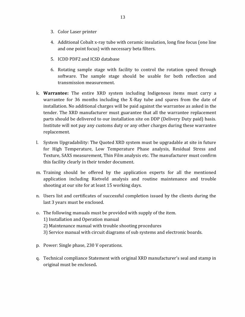
3. Color Laser printer
4. Additional Cobalt x-ray tube with ceramic insulation, long fine focus (one line
and one point focus) with necessary beta filters.
5. ICDD PDF2 and ICSD database
6. Rotating sample stage with facility to control the rotation speed through
software. The sample stage should be usable for both reflection and
transmission measurement.
k. Warrantee: The entire XRD system including Indigenous items must carry a
warrantee for 36 months including the X-Ray tube and spares from the date of
installation. No additional charges will be paid against the warrantee as asked in the
tender. The XRD manufacturer must guarantee that all the warrantee replacement
parts should be delivered to our installation site on DDP (Delivery Duty paid) basis.
Institute will not pay any customs duty or any other charges during these warrantee
replacement.
l. System Upgradability: The Quoted XRD system must be upgradable at site in future
for High Temperature, Low Temperature Phase analysis, Residual Stress and
Texture, SAXS measurement, Thin Film analysis etc. The manufacturer must confirm
this facility clearly in their tender document.
m. Training should be offered by the application experts for all the mentioned
application including Rietveld analysis and routine maintenance and trouble
shooting at our site for at least 15 working days.
n. Users list and certificates of successful completion issued by the clients during the
last 3 years must be enclosed.
o. The following manuals must be provided with supply of the item.
1) Installation and Operation manual
2) Maintenance manual with trouble shooting procedures
3) Service manual with circuit diagrams of sub systems and electronic boards.
p. Power: Single phase, 230 V operations.
q. Technical compliance Statement with original XRD manufacturer’s seal and stamp in
original must be enclosed.
14
2. Field Emission Scanning Electron Microscope
Description of item
Scanning electron microscope for High-resolution morphological and compositional
analysis of materials such as metals, metal oxides, semiconducting materials,
polymers, nano-composites etc.
Specifications of scanning electron microscope
A. Microscope
Resolution: 1.0 nm (at accelerating voltage 15 kV); 1.5 nm (at accelerating
voltage 1 kV).
In low vacuum (SE) (2.0nm at 30kV)
Magnification range: X 25 to X 1,000,000
Accelerating voltage: 0.1 to 30 kV
Probe current: Up to 200nA at 15kV
Electron gun: Schottky field emission with In-Lens gun with warranty for
three years or more.
Specimen Stage: PC controlled large eucentric stage with 5 axes motorized
movements.
X=70mm, Y= 50mm, Z= 1.5 to 25mm and tilt -5 to 70º, tilt = 360º.
Specimen size: 150mm or better.
Ability to view non-conducting specimens
Specimen exchange: Easy sample introduction through an air lock
mechanism
Multi Specimen Holder: For introducing many specimens
Detectors: Upper and Lower SE Detector, BSE, EDS and Low Angle
Backscatter Electron Detector, ET secondary electron detector, Low vacuum
SE detector
Nano-area analysis: Controlled Spot size with high-resolution analysis.
Scanning/Display System: A high-definition display system with 1280 X 960
pixels or better for high quality image in real time under graphical user
interface.
Vacuum System: Fully automated ION pumps & Turbo Molecular pump.
Safety Devices: Devices for protect ion against vacuum, water, power,
nitrogen gas pressure failures and ground fault.
15
System Control
Appropriate microscope control software for alignment, image capture and
archival etc. (system should be capable of automatic gun alignment)
Should offer both automatic and manual control of features like dynamic
focus, topographical contrast, compositional contrast, astigmatism
correction.
Dell/HP make PC with Intel Pentium dual core processor or better, 8GB DDR
RAM or better, 320 GB hard disk or better, minimum 2 No. of USB ports
accessible from the front panel, 52 x or better read/write DVD drive, 2 No. of
24’’ LED monitors, wireless keyboard and mouse.
Anti-vibration table for chamber, microscope column and support for
monitor.
Latest Microsoft Windows based operating system (preferably windows 8)
State of the art software for image acquisition and post processing. All
software features should be open for access with proper licensing.
Utilities such as data archiving software, report generation wizard, multiple
image alignment software and different contrast enhancement
Software: Complete software for image analysis.
B. Energy Dispersive X-Ray EDS Detector Peltier cooled and LN2 Free
Spectroscopy (EDS) System:
1. Motorized Detector Movement
2. Resolution: 127eV or better at MnKα
3. Detection : from Be to U
4. Computer with 24" Monitor
5. Software for Qualitative and Quantitative analysis, Mapping and
6. Point & ID Navigators
7. EDS system software should be designed to be extremely user friendly
catering to applications (a) Elemental analysis, multi element mapping with
chemic information, (b) in built help, (c) Customized reporting,(d) Automatic
qualitative & qualitative analysis, Smart map, Pt& ID – Image correlated area
analysis and automatic data collection in specified analysis area, (e) phase
analysis, (f) spectrum synthesis, etc.
C. Optional : STEM Attachment for Transmission Electron Detecting device, sputter
coater
(2) EBSD attachment
16
D. Future Upgradeability: The specimen chamber should be large and compatible to
accommodate other detectors such as EBSD, WDS, CLD and CCD Camera for future
requirements.
E. Chiller: Cooling Water Circulator.
F. Battery Backup unit: For maintaining the vacuum and electron gun.
G. Sputter Coater (Optional): Carbon Coating of the non-conducting specimens.
H. Standard specimens: For demonstrating the maximum resolution and
magnification capability of FE-SEM and performances of EDS and STEM
attachments.
I. A separate computer with dedicated quantitative image analysis software is to be
provided for image analysis and corresponding data storage. The software should
provide at least the following basic features:
Point, linear and area measurements ( for
volume fraction, particle size and spacing, grain size etc.,)
Line profile
Annotation
Image archival and retrieval
Database (with functionalities)
Spares and consumables
Equipment supplier should provide a complete set of spare and consumables( including
filaments) for three year troublefree operation (Please provide a complete list of spares
with item-wise price)
Calibration standards
Standard samples to check system calibration and other parameters should be supplied.
Documentation: At least two hard copies in original form need to be provided.
The manual shall explain the Safety instructions, general information about
system, testing procedure, instruction for routine and periodical maintenance,
instruction for operation, error message manual, machine calibration manual,
preventive maintenance manual, trouble-shooting manual, electrical and
electronic circuit diagrams, complete list of parts with identification numbers.
Manuals and circuit diagrams
Complete set of manuals for the operation and the servicing of the equipment.
All circuit diagrams, block diagrams and other electrical and mechanical
17
schematics must be provided for main unit, subsystems and accessories
(Including bought-out items).
A list of laboratories in India where same/similar models from the manufacturer
are already in use must be furnished with the bid.
The instrument shall bear 3 years comprehensive warranty.
Pre-Installation Requirements •
Pre-installation requirements such as room size, required power rating, utility requirements – CC chiller, gases (argon, N2) etc. are to be clearly mentioned.
Site inspection and qualification must be performed by vendor’s authorized representative, well in advance of system delivery
Post installation training
One week training on the instrument after its successful installation and commission will be provided for 4 people on the equipment’s operation, maintenance and trouble shooting.
3. Metallurgical Optical Microscopic System (MCL)
A. Microscope
Fully automatic Metallurgical Microscope with bright-field, dark-field and DIC/NIC
and polarizing contrastobservation modes.
A contrast manager for automatically changing the contrast of image.
DIC function should be automatic by just touch of a button –or the polarizer,
analyzer and DIC prisms should be brought in the optical path or by computer control
System integrated automated z-focus with programmable multi-steps. Bid must
specify the no of levels possible in automatic z-focus
Binocular tube
12V 100W illumination with built in power supply AC 90-250V or LED illumination
with separate control box with 2- RS232 and 2- USB ports
Switching of Objective: switching shall be either automatic or manual
The objective turret is motorized/ coded objectives with provision for at least 5
objectives.
18
Manual override facility for the z-focus.
Microscope shall have a manual/motorized reflector turret
It shall have motorized field diaphragm and aperture diaphragm
Parfocality management in sharp images
Constant color intensity control for maintaining the color temperature of the
illumination at 3200 K.
Optional facility to store several settings of microscope and camera for specific
samples including the specific objective used, so Just by selecting the method
microscope and camera will be ready for operation or system prompts for manual
intervention to progress towards the set parameters
Basic stand shall have programmable buttons to change functions like
Illumination manager
Focus functions
Camera port operation
Magnification
Fluorescence functions
Control element for Z and X-Y-stage movement
Manual stage
Position memory slot for fast travel to selected Z positions
Semi Apo Chromatic Objectives between 5x to 100x
Eyepiece 10x/25x
Motorized port for attaching camera
C-mount adapter for Camera
B. Digital camera
• Fast, full color real-time live imaging
• 5 Megapixel High resolution CCD camera
• 12/16/32 bit analog-digital conversion for optimum color reproduction 36 bit color
depth
• Color or gray-scale images
• Large 3.4 µm x 3.4 µm pixel size for high sensitivity Binning facility
• Exposure time of 1 ms to 60 seconds
19
• Intuitive user interface with convenient image capture and image editing functions
• Shading correction applied to live and captured images
• FireWire B interface for compatibility with a wide range of computers
• Ultra compact metallic housing for thermal noise dissipation
C. Computer interface
PC with high end graphics card, 22” LCD monitor & HP/Canon laser monochrome
printer
Any peripheral required for interfacing and operation of computer with other
elements of the microscopic system
D. Camera Control Software
Camera should be supplied with software with following facility.
o Complete control of the camera functions like white balancing, Gamma, color
saturation, exposure time should be possible.
o Facility for both Monochrome and color images should be possible
o Facility to invert the images both vertically and horizontally should be possible
o Control facility for the microscope should be possible
o If the details of objective, eyepiece, magnification changer and C-mount is fed in the
software, it should do automatic calibration .
o Facility for manual calibration with stage micrometer should be possible
o Facility to compare live image and stored image side by side on the screen should be
possible.
o Stitching the individual images manually for getting the mosaic image of the sample
should be possible.
o Micron marker, point to point length measurement, Annotation should be possible
E. Software
Microscope system software conforming to applicable ASTM, ISI,DIN and JIS standards:
Basic Software enabling the functionality of microscope, enabling the interfacing
the other application softwares and report generation capability
Quantitative metallography software that demonstrates interactively the point, lineal,
areal, aspect ratio measurements on the sample.
20
Phase analysis software
Nodularity and nodule count analysis software for cast irons
Grain size, shape analysis software.
F. Optional items
All additional add-ons (both hardware and software) that enhance/extend the capability of
configuration need to be quoted as optional items.
G. Manuals
Operation and maintenance manual: At least two hard copies in original form need to be
provided. The manual shall explain the Safety instructions, general information about
system, testing procedure, instruction for routine and periodical maintenance, instruction
for operation, error message manual, machine calibration manual, preventive
maintenance manual, trouble-shooting manual, electrical and electronic circuit diagrams,
complete list of parts with identification numbers.
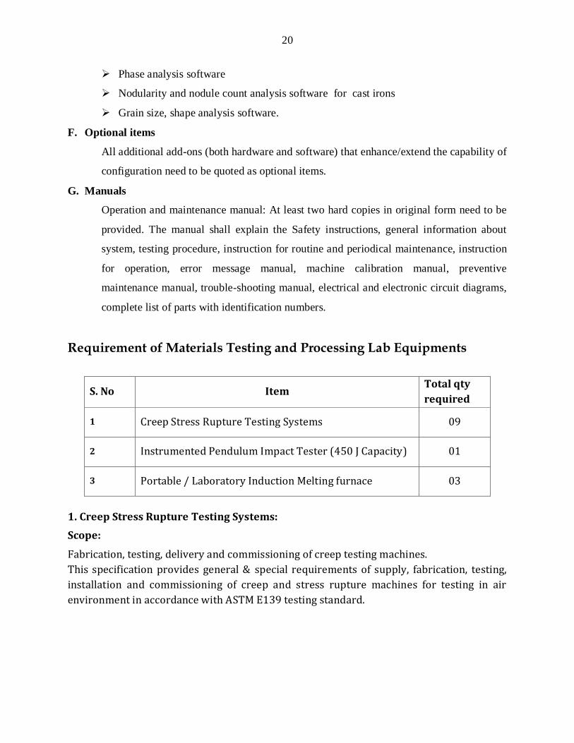
Requirement of Materials Testing and Processing Lab Equipments
S. No Item Total qty
required
1 Creep Stress Rupture Testing Systems 09
2 Instrumented Pendulum Impact Tester (450 J Capacity) 01
3 Portable / Laboratory Induction Melting furnace 03
1. Creep Stress Rupture Testing Systems:
Scope:
Fabrication, testing, delivery and commissioning of creep testing machines.
This specification provides general & special requirements of supply, fabrication, testing,
installation and commissioning of creep and stress rupture machines for testing in air
environment in accordance with ASTM E139 testing standard.
21
A. General specifications of the systems :
1. The machine shall comprise a loading frame with an integral control cabinet. A load of up to 50kN is to be applied through a lever arm with a single lever ratio of 1 : 20 and a load accuracy of +/- 0.5 %.
2. The machine shall be equipped with a three zone furnace to carry out the tests at high temperature in the range 373 K to 1273 K with an accuracy of +/- 1 K. The uniform hot zone temperature will be ensured on the test specimen over a length 150 mm.
3. High precision, high accuracy temperature controller and power control unit is to be employed to achieve the above mentioned temperature accuracy.
4. Separate controllers would be employed to control the temperature of each zone. The detailed specifications of the furnace and temperature controller with power supply unit are specified below. Since the creep tests are of longer duration, the furnace shall perform uninterruptedly during the creep test.
5. Automatic load lever beam leveling device with over travel trips shall be given. Provisions shall be made to prevent the motorized draw head assembly from exceeding the limits during manual or mechanical operations.
6. There shall be a provision to manually operate the draw head motor (i.e. the motor and gear assembly which supports the creep specimen train) electrically to move it up or down. During the test, it shall be ensured the draw head motor moves down automatically by the above said beam-leveling unit.
7. There shall be a provision to de-clutch the motor assembly from the gear assembly so that (hand wheel or equivalent) the specimen train assembly can be moved up or down manually.
8. The specimen elongation (strain) shall be measured by using Linear Variable Differential Transformer (LVDT) during the test.
9. Signal conditioner and scanning unit for LVDT shall also be supplied.
10. Continuous temperature and strain measurements and also storage and analyses of data are required through computer controlled data acquisition system.
11. There shall be a provision to automatically shut off the electrical power to the machine when the specimen breaks.
12. The operating power for the whole control cabinet and the furnace would be of 230 volts single phase 50 Hz.
13. The main switch and the other switches for temperature controllers, elevator motors etc. shall be provided with suitable good quality circuit breaker for the safety reasons.
14. Fuses shall be used wherever required and the fuse points shall be easily accessible.

22
15. Spirit level shall be mounted on top of lever arm in each machine, so that the horizontal position of the beam can be confirmed periodically or as and when required.
16. Provision shall be there, to put off the power to the furnace, in case of overshooting of temperature due to malfunctioning of any of the temperature controllers.
B. Mechanical Systems :
The mechanical system shall comprise of the following:
a. Frame: The material for the frame is of suitable mild steel (MS) or equivalent. All the MS components shall be painted or powder coated.
b. Lever Arm.
c. Clutch and Draw Head Assembly
d. Elevator
e. Hand Wheel
f. Motorized Load Train assembly
g. Three pairs of adaptors / grippers shall be supplied with each machine. M8, M10, M12 with standard pitch.
h. Clevis and Coupling
i. Stud
j. High temperature Creep Extensometer
k. Weights of denominations suitable to entire range of 5000 Kgf( Lever Arm is 1:20} . Weights have to be supplied in Newtons. Conformity by the supplier shall be done.
C. Furnace Specifications:
Number : One with each machine
Type: Three-zone vertical cylindrical furnace shall be of split construction hinged in the rear. Other end will have provision for locking at top and bottom using CAMLOC type of assembly or equivalent.
Top and bottom finish insulation: shall be low thermal conducting (low „K‟ factor)
vacuum cast ceramic fiber insulation to provide minimum heat loss, high temperature capability and for rigid structure.
Exterior Finish: The outer shell shall be made by a bright stainless steel 1.4 mm thick or above. Closures at top and bottom of the furnace shall l fit snuggly around pull bars and reduce the heat loss at these points.
Provisions shall be there to seal the top and bottom of the furnace by the compressed cast ceramic fiber insulation.

23
Clamps or equivalent can be provided to keep the tight fitting of the above thermal insulation boards to seal the leakages.
Dimensions : ( Aproximate. )
Outer Diameter : 14‟ ( 350 mm or more. )
Inner Diameter : 3‟
Height : 15‟ ( 375 mm or more upto 400 mm)
Uniform temperature zone at the middle of the furnace shall be of 150 mm.
The power supply terminals to the furnace shall be kept near the hinges
Heating Element: Kanthal – A1
Max Temperature: 1100 deg C
Operating Voltage: 230 V AC single phase 50 Hz.
The rear-hinged part of the furnace shall be mounted on the machine frame such that the frame position of the furnace is adjustable vertically.
D. Detailed Specifications of PID Temperature Controllers and Thyristor Power Control Units
PID Temperature Controller : Three Numbers with each machine m
High quality controllers of EUROTHERM Make or equivalent
Input :
1. Temperature Range : 0 – 1373 K
2. Input Range : +/- 100 mV and 0 to 10 VDC ( Auto ranging )
3. Sample rate ; 9 Hz (110 mS )
4. Calibration accuracy : 0.25 % of reading +/- 1 LSD, +/- 10 C/F
5. Resolution : < 1uV for +/- 100 mV range, < 2.0 mV for +/- 10 VDC range.
6. Linearization Accuracy :< 1.0 of reading
7. Input filter : 1.0 to 999.9 seconds
8. Zero filter : shall be available
Thermocouple :
1. Cold Junction compensation Automatic
2. Thermocouple break protection shall be available
3. Output Relay output and control output (4-20 mA)
Control Functions :
1. Modes PID or PI with overshoot inhibition, PD, PI, P only on/off
24
2. Application Heating and cooling
3. Auto/manual Bump less transfer
4. Set point rate limit 0.01 to 99.99 degrees or displays units per minute
5. Cooling algorithms Linear
6. Tuning: One-shot tune Automatic calculation of PID and overshoot inhibition parameters
7. Automatic droop Automatic calculation of manual reset value when using PD control
8. Alarm types Full scale high or low, Deviation high, low, or band.
General :
1. Display Dual, 4 digit x 7 segment high intensity LED
2. Dimensions 48 x 48 x 103 mm (width, height and depth respectively)
3. Supply 230 V AC, 50 Hz, 10 Watts max
4. Temperature and RH 0 to 55 deg C RH: 5 to 90 % non-condensing
5. Panel sealing
6. Non-volatile EERPOM shall be available
Thyristor Power control units : One number for each Zone ( High quality type from reputed)
1. Load type Constant resistance
2. Power supply 230 V AC, 50 Hz
3. Heater voltage 230 V AC
4. AC current rating 15 A
5. Firing mode Phase angle
6. Input 4-20 mA DC
7. Manual Input Input impedance 330-kilo ohms
8. Slave output +10 V
9. Operating temperature upto 50 deg C
10. Mounting Din Mounting
11. Current limit Adjusted from 10 to 100%
12. Compatibility Will be compatible with the above temperature controller
Detailed Specifications of LVDT
Linear Variable Displacement Transducer (LVDT):[ One Number with each machine ]
- Inductive Spring loaded type
25
- 0-10 mm range, Stroke + / - 5 mm or + / - 10 mm
- Linearity deviation: +/- 0.5 % of full scale
- Repeatability: +/-0.1 % of full scale
- Excitation: 1 V rms ~ 4 kHz sinusoidal
- Sensitivity: Better than 20 mV/V/mm
- minimum 3 m long coaxially shielded cable with matching connectors at both ends
Programmable Eurotherm 12 (twelve) channel 6100A DATA LOGGER, facility to log LVDT, Thermocouple, load cell etc.
Computer , Printer and Workstation : [ One SET ]
- Latest Pentium series CPU workstation, with 22” LCD Monitor x Key Board x HP Laserjet B & W Printer + UPS for 25 minutes battery backup.
E. Optional Grips& Accessories
* Additional SET of inserts per SET of any sizes ( for Round / Flat specimens )
* Load Cell Capacity: 50kN with Amplifier [ Optional ]
Packing, Freight, Forwarding and Insurance Charges must be quoted separately
Installation and commissioning has to be carried out at three campuses of RGUKT by the supplier.
Performance tests have to be demonstrated at RGUKT’s laboratories.
Two Personnel of RGUKT have to be trained for a week on the installed machines
2. Instrumented Pendulum impact tester (450 J capacity)
Item description
Bid for the Supply, installation, commissioning, and user training of notched bar
impact testing of metallic materials system for carrying out tests of standard Impact
energy determination tests including Ductile Brittle Transition Temperature
determination, and dynamic fracture toughness evaluation as per GB/T19748-
2005, ISO 14556: 2000(E), ASTM E23 etc
1. Specifications:
The machine, accessories shall provide experimental capability with sufficient
accuracy in controlling test and data acquisition parameters for the following types
of tests:
26
Instrumented Charpy tests for steels to determine dynamic fracture toughness and
dynamic load-deflection behavior with specimens of sizes of 10 x 10 x 55 mm,
Fixture or attachment for low to above ambient temperature shall be quoted as
optional item.
The instrumented tups, anvils and fixtures supplied shall be capable to conduct
above mentioned impact tests on specimens specified therein.
2.1 Essential features of machine:
A. Main frame and accessories
The machine shall provide the impact energy in the range of up to 450 J with a
resolution better than or equal to 0.1 J
The total friction and windage lossesof the machine during the swing in the
striking direction shall not exceed 0.5 % of the scale range capacity.
The instrumented striker assembly for the Instrumented Charpy test should be
attached with integral force transducer, Full scale ±50 kN with 0.01 kN or better
resolution.
The velocity of the striker on the point of impact shall be adjustable over a wide
range of 1m/s to 5 m/s.
The overall system shall be designed to be very rigid, to minimize vibration and
machine compliance issues.
The system shall ensure minimum energy loss due to base flexure.
Charpy fixture shall able to accommodate different specimen dimensions by using
appropriate sized Charpy supports precisely positioned via set pins/other suitable
means.
Quick-change adapter plates shall be supplied to adapt the pendulum impact
tester to different specimen widths.
Option for manual control for setting up the impact point with the specimen shall
be provided.
The suitable fixture shall be supplied to ensure that anvils are accurately
positioned relative to the tup.
27
Anvils shall be designed to be easily and inexpensively replaced independently of
the supports or adapter plates.
Control systems shall provide electrically driven motorized system fitted with
brake for positioning and releasing of the pendulum.
Power Supply: 230 V, 50 Hz AC
B. Safety
1) Access to specimen area should be protected when impact mass are in unsafe
position.
2) Adequate Safety enclosure with electric interlock and clear visibility for easy
viewing of the specimen during testing shall be provided.
3) Projectile resistant arrangements must be ensured.
4) All safety systems should be dual circuit and fail-safe.
5) No unsafe release of the impact mass shall be possible under any of the following
conditions:
a. Failure of mains power supply
b. Failure of compressed air supply
c. Failure of control software
6) Any other added safety feature may be described fully and quoted separately.
7) The impact tester must have a safety encompassing and safety regulations must
comply with CE and other international norms.
C. Direct Dynamic Force Measurement System
The machine must be accompanied by a system for directly measuring the dynamic
force/displacement/energy of the specimen as a function of time during contact of
striker with the specimen for a temperature range of – 180 °C to + 200 °C.
Force-time data must be precisely triggered and shall be accomplished by
continuously monitoring the load signal and saving data when a significant
rise in load occurs.
The system shall be capable of recording rapid load change events of the
specimen.
28
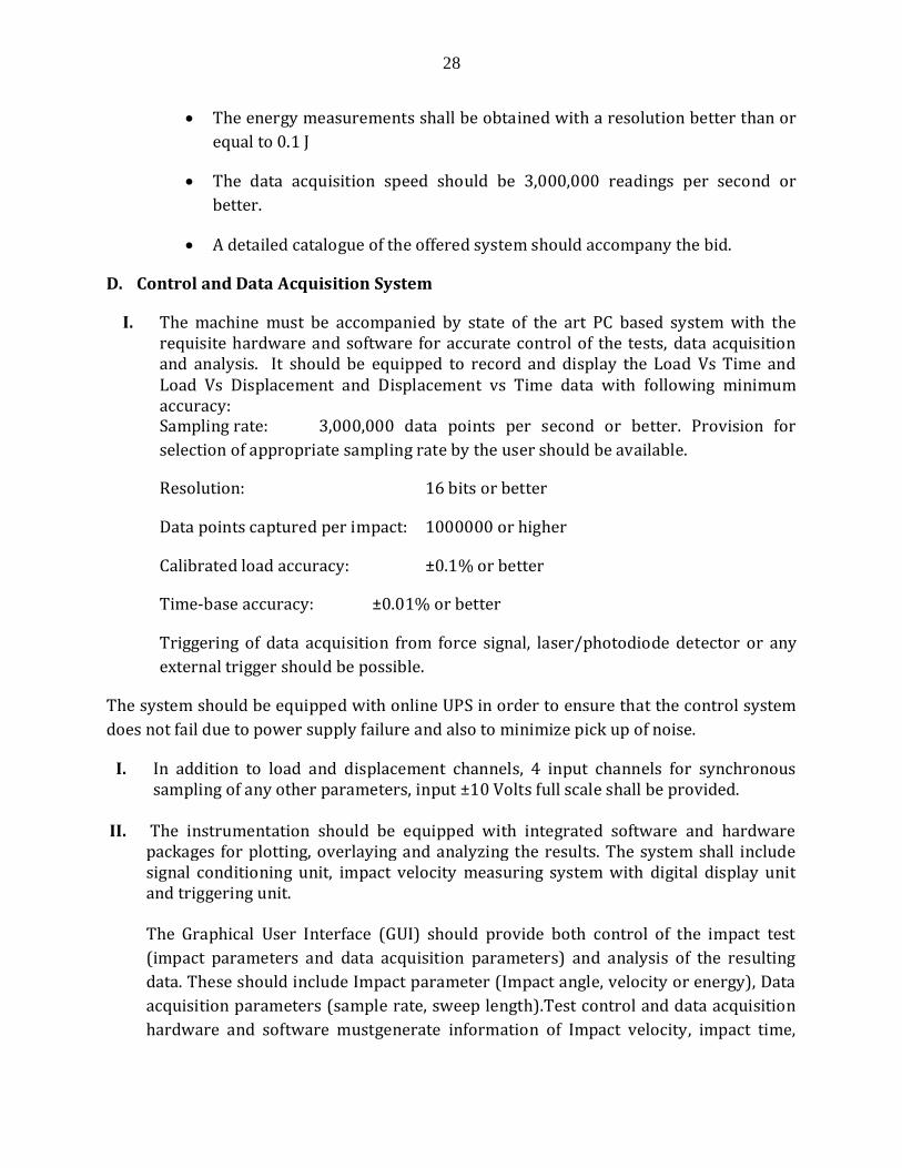
The energy measurements shall be obtained with a resolution better than or
equal to 0.1 J
The data acquisition speed should be 3,000,000 readings per second or
better.
A detailed catalogue of the offered system should accompany the bid.
D. Control and Data Acquisition System
I. The machine must be accompanied by state of the art PC based system with the requisite hardware and software for accurate control of the tests, data acquisition and analysis. It should be equipped to record and display the Load Vs Time and Load Vs Displacement and Displacement vs Time data with following minimum accuracy: Sampling rate: 3,000,000 data points per second or better. Provision for
selection of appropriate sampling rate by the user should be available.
Resolution: 16 bits or better
Data points captured per impact: 1000000 or higher
Calibrated load accuracy: ±0.1% or better
Time-base accuracy: ±0.01% or better
Triggering of data acquisition from force signal, laser/photodiode detector or any
external trigger should be possible.
The system should be equipped with online UPS in order to ensure that the control system
does not fail due to power supply failure and also to minimize pick up of noise.
I. In addition to load and displacement channels, 4 input channels for synchronous sampling of any other parameters, input ±10 Volts full scale shall be provided.
II. The instrumentation should be equipped with integrated software and hardware packages for plotting, overlaying and analyzing the results. The system shall include signal conditioning unit, impact velocity measuring system with digital display unit and triggering unit. The Graphical User Interface (GUI) should provide both control of the impact test
(impact parameters and data acquisition parameters) and analysis of the resulting
data. These should include Impact parameter (Impact angle, velocity or energy), Data
acquisition parameters (sample rate, sweep length).Test control and data acquisition
hardware and software mustgenerate information of Impact velocity, impact time,

29
impact energy, absorbed energy, displacement, crack forming energy, crack extension
energy, yield load, yield time, peak load, time of peak load, displacement of peak load,
energy of peak load, unstable crack extension start load, unstable crack extension stop
load, unstable crack extension start energy etc from test.Details of the measured
parameters, and those obtained by data conditioning and manipulation must be
specified.
E. Calibration Certificates
Calibration certificates from internationally recognized authorities for the load and
displacement measurement systems should be provided according to ASTM E23.
F. Other requirements:
The quote shall also include the non-contact angle measuring system.
The quote shall include the details of pendulum length, dimensions
(with/without protection device) and approximate weight.
Packing and protection requirement for transit
Installation requirements must be clearly mentioned.
The quote shall include Tool box, any special spanners/tools etc. for normal
maintenance of the machine.
Complete set of service manuals in English
An updated list of users for the machine and environment chambers supplied to
India.
Installation & Commissioning: The bid cost should include installation and
commissioning of the equipment with all accessories at user’s site. The supplier
should demonstrate the performance of the equipment to the specifications by
conducting trial tests. Complete set of manuals for operation, maintenance and
safety along with circuit/block diagrams should be provided. Pre-installation
requirements along with their detailed technical specifications for smooth
running of the equipment should be specified. Also specify requirement of
electric.
E. Spares
The offer shall include, separately, the bid for supply of sufficient spares for 3 years
of trouble-free and smooth operation of the systems.
30
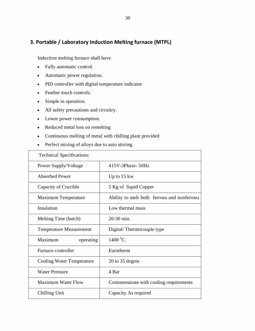
3. Portable / Laboratory Induction Melting furnace (MTPL)
Induction melting furnace shall have
Fully automatic control.
Automatic power regulation.
PID controller with digital temperature indicator
Feather touch controls.
Simple in operation.
All safety precautions and circuitry.
Lower power consumption.
Reduced metal loss on remelting
Continuous melting of metal with chilling plant provided
Perfect mixing of alloys due to auto stirring
Technical Specifications:
Power Supply/Voltage 415V-3Phase- 50Hz
Absorbed Power Up to 15 kw
Capacity of Crucible 5 Kg of liquid Copper
Maximum Temperature Ability to melt both ferrous and nonferrous
metals Insulation Low thermal mass
Melting Time (batch) 20-30 min.
Temperature Measurement Digital/ Thermocouple type
Maximum operating
temperature
1400 0C.
Furnace controller Eurotherm
Cooling Water Temperature 20 to 35 degree
Water Pressure 4 Bar
Maximum Water Flow Commensurate with cooling requirements
Chilling Unit Capacity As required
31
NOTE
A complete set of bidding documents may be purchased by interested bidders from the
RGUKT contact person upon payment of the bid document price which is non-refundable.
Payment of bid document price should be by demand draft drawn from any Nationalized
Bank only in favour of “Registrar, Rajiv Gandhi University of Knowledge Technologies” and
payable at Hyderabad (India).
Tender documents purchased bidders are only allowed to participate in Pre-
Bid meeting