Embed Size (px)
Citation preview
Rajesh Kumar Ojha and P. V. Joshi 1
International Journal of Recent Trends in Mechanical Engineering (IJRTME—ISSN: 2347 - 7326) Vol. 2, Issue. 4, June. 2014
Numerical Analysis of Forced Convection andHeat Transfer in Curved Duct
Rajesh Kumar Ojha1 and P. V. Joshi2
1 Mechanical Engineering department, CSIT,Durg2 Mechanical Engineering department, SSGI,Bhilai
Abstract— Analysis of fluid flow and heat transfer in fourReynolds number flow square 3D duct bend is undertaken.Numerical study of a constant property Newtonian fluid air in120° and 160° square curved duct is presented under steadyand laminar flow. The main purpose of this work is to analysisforced convection and heat transfer simulations by using Ansys14.0 Fluent software for the four Dean numbers 150, 300, 700and 1500. Two different situations are studied in closed curvedduct flow. Different parameters are changed in each case toobtain different results, such as the 120° and 160° curvedchannel and the values of the velocity and temperaturecontours for each phase.
Keywords: CFD; fluid flow; heat transfer; duct.
I. INTRODUCTION
Fluid flow and heat transfer continues to be a major field ofinterest to engineering and scientific researchers, as well asdesigners, developers, and manufacturers. The wealth ofapplications includes a wide variety of components andsystems for energy devices, including general powersystems, heat exchangers, high performance gas turbines andother power conversion devices. Other areas of interestinclude chemical processing, general manufacturing, bio-heat transfer, electronic cooling, comfort heating andcooling, and a number of natural phenomena from upwellingcurrents in the oceans to heat transport in stellaratmospheres.Flow with curvature is very common inengineering application. Curved ducts of various crosssections are used widely in many industrial devices such asthe passages of turbo-machinery components, solarcollectors, inlet diffusers of rocket engines, heat exchangers,cooling systems, refrigeration and air conditioning systems.Flow in curved tubes is different from flow in straight ducts.
Rajesh Kumar Ojha, Asst. Professor, Department of Mechanical Engg,CSIT Durg (CG), Email: [email protected] ,[email protected]. V. Joshi , Sr. Associate Professor, Department of Mechanical
Engg,SSGI, Bhilai
II. LITERATURE REVIEW
M. Raisee et al studies has considered the application oflow-Re linear and non-linear eddy-viscosity models fornumerical prediction of the velocity and pressure fields inflow by two 900 curved ducts, In which one is square cross-section and other one is a rectangular cross-section. Thecomputations have shown how the curvature of a 90◦ bendinfluences the flow field characteristics of turbulent flowwhich is developing. It was shown that for the bend ofsquare cross-section the curvature produced a strongsecondary motion, while for the rectangular cross-sectionthe secondary motion is confined to the corner regions.Curvature is also influences the flow development alongwith the straight upstream section of the duct by introducinga weak cross-duct motion near the entrance of the curvedsection. Curvature causes the pressure gradient to changesign along the convex and concave walls of the curvedsection, which results in local redistribution of the stream-wise velocity profile along the curved section.M. Norouzi et al Studies the current research, 80×40 squaregrids is used as calculation mesh. For the CEF fluid flow ina curved duct with Re = 1000 , δ = 0.1, Ψ = 1 and Ψ / Ψ =−5%, the mean error of axial velocity distribution in 80×40grid compare to 120×60 grid is around 0.23%. Therefore, itconfirmed that the numerical solution of 80×40 grid is gridindependent for this condition. On viscoelastic fluids flowin curved duct, with a rise in first normal stress difference,intensity of Taylor- Gortler vortices and mean Nusseltnumber are increased.Benny Kuan et al studied that the numerical simulations areperformed for dilute gas-solid flow in a rectangular ductconsisting of a horizontal-to-vertical bend. A very low solidmass loading is considered and the bend has a turning radiusof 1.5 duct diameter. The measured and calculated meanparticle velocities are presented in the form of figure. Thenumerical results compare favorably with the data, except inregions close to the outer wall upstream and 30° into thebend. At these locations, the calculated particle velocitytends to exceed the measured values by as much as 70%.One possible explanation to this disparity would be that theparticles are much better suspended in the experiment thanthey are in the calculation. Chances of particles impactingonto the outer wall are thus greatly reduced. Near- wallparticles in the experiment are then able to closely followthe gas flow pattern.Haydar Kucuk studied that the entropy generation for hydro-dynamically and thermally fully developed, steady,incompressible laminar flow with constant physicalproperties in the concentric curved annular duct with square
Rajesh Kumar Ojha and P. V. Joshi 2
International Journal of Recent Trends in Mechanical Engineering (IJRTME—ISSN: 2347 - 7326) Vol. 2, Issue. 4, June. 2014
cross-section was numerically investigated under constantwall temperature boundary condition. The effect of fluidfrictional irreversibility is highly lower than heat transferirreversibility on volumetric entropy generation for laminarflow in concentric curved annular square duct underconstant wall temperature boundary condition. The variationof volumetric entropy generation due to fluid frictionalirreversibility in the concentric curved annular ducts isdirectly affected by the secondary flow created bycentrifugal.K. Mohanarangam et al Studied Simultaneous measurementsof both the gas and solid phases in a dilute turbulent two-phase flow system inside a 90o duct bend have beensuccessfully investigated. Size discrimination techniqueusing a PDA was used to separate the gas from theparticulate phase. Stream wise and transverse velocities ofclean gas (without the particles) and unclean gas (withparticles) were compared along various sections of the bendand the vertical duct past the bend. It is concluded that themean velocities of the unclean gas lagged behind the cleangas and this was mainly due to the effect of particle drag orthe part of energy spent by the gas phase moving theparticles within its flow field. The current experimental datacan be used to further enhance CFD models, to aid betterprediction near the inner wall of the bend by establishing aneffective two way coupling between the gas and theparticulate phases.Jer-Huan Jang et al studied that the effects of walltranspiration on mixed convective flow and heat transfer ininclined ducts have been studied numerically. A vorticity-velocity method and a marching technique have beenemployed to solve the three dimensional problem. Theeffects of wall Reynolds number, aspect ratio, modifiedRaleigh number, and mixed convection factor on theaveraged local friction factor and Nusselt number aresystematically studied As inclination angle increases, thebuoyancy effect increases as well which causes an unstablesecondary flow resulting the fluctuation in the distribution offriction factor and Nu.Tony W. H. Sheu et al studied that, the three-dimensionalsteady-state Navier-Stokes equations, subject to theincompressibility constraint condition, are solved byemploying the streamline upwind finite element model so asto enhance convective stability and to minimize the falsediffusion error. To resolve asymmetry and indefinitenessproblems in the large-size finite element matrix equations,we have applied the element-by-element BiCGSTABiterative solver for improving the convergent performance.At a stream wise plane that is upstream of the bend with alength of 2, the location with the peak axial velocity at theplane of symmetry shifts towards the outer wall owing to thecentrifugal force. The skewed axial flow rapidly intensifiesup to about θ = 300. This progressively developing flow isaccompanied by an accelerated flow in regions near theinner-radial wall. In the bend between the 0o and 40o streamwise planes, the fluid flows near the outer wall are seen to begreatly decelerated due to the adverse longitudinal pressuregradient. Conversely, the favorable pressure gradientobserved at the suction side of the bend can cause the flowto accelerate.
M. H. Kayhani et al studies the Secondary flowsstreamlines in a quarter of cross section for different aspectratio is shown in fig. there are eight vortex flows in squarecross section and two vortexes in the quarter cross section .When the aspect ratio changes, four vortexes were deletedgradually and thus four vortexes remain. These remainedvortexes will be weak gradually. The secondary flowsdirection is opposite to the secondary flows that are in theturbulent Newtonian fluid flow.Hosseinali Soltanipour et al studied that forced laminar flowof γ-AL2O3/water nanofluid and heat transfer behaviors in aribbed curved duct have been investigated using controlvolume method. Result have been presented for a range ofDean number (500≤De≥200), three rib sizes (h/a =1/10 , 1/7,and 1/5) and particle volume fraction ranging 0-10%. In caseof water flow in ribbed duct, significant heat transferenhancement (relative to smooth duct) is achieved without alarge pressure-drop penalty. For γ-AL2O3/water nanofluidflow in smooth duct (for De=500),the maximum heattransfer coefficient is approximately 1.72 times of waterflow and corresponding pressure drop ratio is 6.8.B. T. Kuan studied the dilute gas-solid flow through acurved 900 duct bend are performed. Flows with twodifferent size distributions of glass spheres having meandiameter 66 µm and 77 µm are considered. The curved bendis square-sectioned (150 mm × 150 mm) and has a turningradius of 1.5 times the ducts hydraulic diameter. Meanvelocities for both gas and the dispersed phases are solvedwith DRSM on three grid systems having different cross-sectional cell densities (that is, 40 × 40, 60 × 60 and 80 × 80cells). According to the figure, the predicted gas flow isessentially grid independent, except at the inner duct walljust downstream of the bend exit. This corresponds to aregion where local turbulence intensity grows rapidly as thebulk gas flow reattaches to the inner wall after the bend.Kazimierz Rup et al the authors describe an attempt toutilise installed square- sectioned elbows in order to measurethe fluid flow rate. In order to practically accomplish themeasurement of the volumetric flow rate of the air, a specialresearch stand has been built, and square shaped elbowshave been installed (80 × 80 mm in dimension). Thenumerical computations were carried out with the help ofFLUENT 6.2 software package. The obtained results werecompared to corresponding ones coming from orificemeasurements and from experimental work available in theliterature. The authors studied the indirect method used tomeasure the volumetric flow rate of a fluid is characterisedby high accuracy and repeatability. The high accuracy ispossible due to a very realistic mathematical model of thecomplex flow in the curved duct.Quamrul H.Mazumder studied Computational fluiddynamics (CFD) analysis was performed in four different 90degree elbows with air-water two-phase flows. The insidediameters of the elbows were 6.35mm and 12.7mm withradius to diameter ratios (r/D) of 1.5 to 3. The pressuredrops at two different upstream and downstream locationswere investigated using empirical, experimental, andcomputational methods. The combination of three differentair velocities, ranging from 15.24 to 45.72 m/sec, and ninedifferent water velocities, in the range of 0.1–10.0 m/s, wasused in this study. CFD analysis was performed using the
Rajesh Kumar Ojha and P. V. Joshi 3
International Journal of Recent Trends in Mechanical Engineering (IJRTME—ISSN: 2347 - 7326) Vol. 2, Issue. 4, June. 2014
mixture model and a commercial code, FLUENT. the testloop, consisting of a 30-gallon water tank, a 25 HP pump, a10 CFM air compressor, liquid and gas flow meters, fourvertical to horizontal 90◦ elbows with two different pipediameters and r/D ratios, inlet and outlet pressure gauges,and four differential pressure gauges. Air from thecompressor enters the test loop, through a gate valve and airflow meter, that is used to control the air flow rates. Waterfrom the tank is pumped into the test section, through a gatevalve and liquid flow meter that is used to control the waterflow rates.Kyung Hwan Kim et al Fluid flows in three rectangular ductsystems are studied by using comparisons betweenmeasurements with LDV and numerical computations withcommercial software. The systems in this study are arectangular duct with a 90 degree bent elbow, a rectangularduct with two outlets, and a rectangular duct in theintermediate of which a circular cylinder is located. Thesestudies For the case of the rectangular duct with a 90 degreeelbow, there is relatively good agreement in the principalvelocity between the measurements and numericalcomputations. Important differences were noted in theturbulent kinetic energy levels between them. In the case ofthe rectangular duct with two branches, the calculatedvelocity contour at the exit of each branch differs from themeasured velocity contour at the same cross section.However, numerical simulations for the delivery ratio toeach branch are possible compared to the measurements ofthe ratio. For the fluid flow past the cylinder in a rectangularduct, disagreements in the velocity and turbulent kineticenergy levels in the wake region behind the cylinder werefound between the numerical computations and themeasurements. However, there was good agreementbetween them for the Nusselt numbers of the heatedcylinder.Quamrul H. Mazumder studied that CFD analysis of singleand two phase flow in a 12.7 mm elbow was performedusing FLUENT. Analysis per- formed for three different airvelocities between 15.24 - 45.72 m/sec and three differentwater velocities of 0.1 to 10.0 m/sec. Pressure drop profilesand cross-sectional pressure contour maps were presentedfor characteristic flow behaviors in both single and multi-phase flows. CFD results were compared with two differentexperiential models showing realistic agreement. To predictpressure drop in elbows for single and multi- phase flows anumber of empirical models have been evaluated. Thesemodels can be classified into four basic groups: regularmodel, divided flow model, dimensional and similitudeapproach and Chisholm approach. All these models useglobal approaches because they do not make any referenceto a specific flow pattern presented in the elbow. Theseapproaches, with the exception of the homogeneous model,were developed using experimental data provided by severalauthors. For low water velocity of 0.1 m/sec, Chisholmmodel predicted pressure drops were higher than both CFDand Churchill model predictions. At 1.0 m/sec watervelocity, Benbella model predicted higher pressure dropcompared to Chisholm model with even higher predictionsin CFD results.
III. DESCRIPTION OF THE PHYSICAL PROBLEM
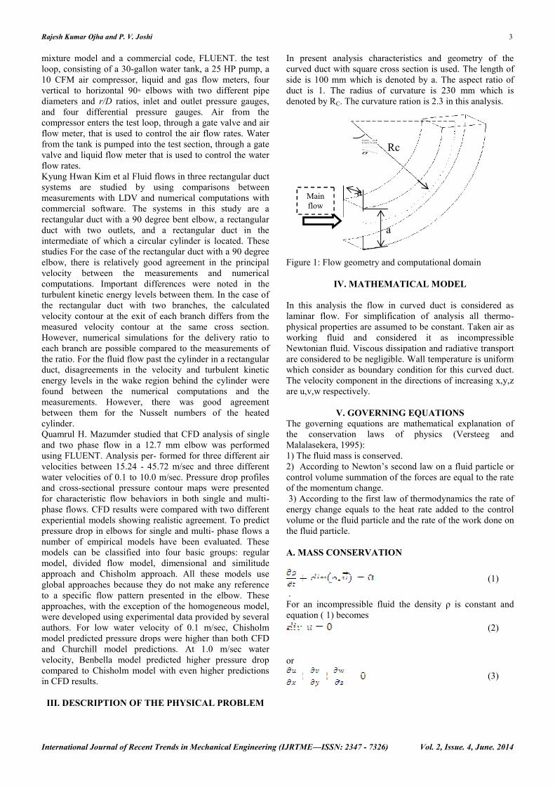
In present analysis characteristics and geometry of thecurved duct with square cross section is used. The length ofside is 100 mm which is denoted by a. The aspect ratio ofduct is 1. The radius of curvature is 230 mm which isdenoted by RC. The curvature ration is 2.3 in this analysis.
Figure 1: Flow geometry and computational domain
IV. MATHEMATICAL MODEL
In this analysis the flow in curved duct is considered aslaminar flow. For simplification of analysis all thermo-physical properties are assumed to be constant. Taken air asworking fluid and considered it as incompressibleNewtonian fluid. Viscous dissipation and radiative transportare considered to be negligible. Wall temperature is uniformwhich consider as boundary condition for this curved duct.The velocity component in the directions of increasing x,y,zare u,v,w respectively.
V. GOVERNING EQUATIONSThe governing equations are mathematical explanation ofthe conservation laws of physics (Versteeg andMalalasekera, 1995):1) The fluid mass is conserved.2) According to Newton’s second law on a fluid particle orcontrol volume summation of the forces are equal to the rateof the momentum change.3) According to the first law of thermodynamics the rate of
energy change equals to the heat rate added to the controlvolume or the fluid particle and the rate of the work done onthe fluid particle.
A. MASS CONSERVATION
(1).
For an incompressible fluid the density ρ is constant andequation ( 1) becomes
(2)
or
(3)
mmmmMainflow
Rc
a
a
Mainflow
Rajesh Kumar Ojha and P. V. Joshi 4
International Journal of Recent Trends in Mechanical Engineering (IJRTME—ISSN: 2347 - 7326) Vol. 2, Issue. 4, June. 2014
B. MOMENTUM CONSERVATION
According to the second law of Newton the net forces on afluid particle is equal to the net momentum change of theparticle. There are two kinds of forces on a fluid particle;body forces such as gravity or Coriolis or centrifugal andsurface forces such as pressure or viscous forces.The momentum equation in the x direction:
(4)
(5)
(6)
The SM terms are the representative of the body forces and u,v and w are the velocity components.
C. ENERGY CONSERVATION EQUATION
According to the law of thermodynamics the energy changerate for a fluid particle is the rate of work done on the fluidparticle in addition to the heat added.
(7)(8)
The term consists of internal energy and the kineticenergy. The term is the energy term related to a source.The term including the temperature gradient is the heattransfer to the fluid and the rest terms of the right side arethe work done on the fluid particle. When air flows in thechannel the governing equations consist of continuity,momentum and energy equation.A parabolic velocity profile is imposed at the inlet of thecurved duct so that hydrodynamic entrance length requiredto obtain a fully developed velocity profile before heatingbegins. Hydrodynamic entrance length is given as
The temperature of air (working fluid) is set to 298 K at inletof curved duct. Standard no-slip boundary condition wasused on the walls of the curved duct. A constant walltemperature boundary condition was set on the externalwalls of curved duct. The walls temperature is set to 313 K.
Overall flow and heat transfer of laminar forced convectionin 3D duct for design point of view are indicated by Nusseltnumber. The average Nusselt number for the duct is given as
Where (m) is the hydraulic diameter define as
with A (m2) being the cross sectional area of the duct and P(m) is the wetted perimeter, hm (Wm-2K-1) is the averageheat transfer coefficient, k (Wm-1K-1) is the thermalconductivity, qw (Wm-2) is the average heat flux, Tw (K) isthe constant wall temperature of fluid and define as
In which Tbi and Tbo (K) are the inlet and outlet bulktemperature respectively.One of important dimensionless quantity is the Reynoldsnumber which is given by
Where ρ (kgm-3) is the density of fluid, um (ms-1) is theaverage axial velocity, Dh (m) is the hydraulic diameter, andμ (kgm-1s-1) is the dynamic viscosity of fluid. Dean numberis define as
Where Dh (m) is hydraulic diameter and Rc (m) is the meanradius of curvature.
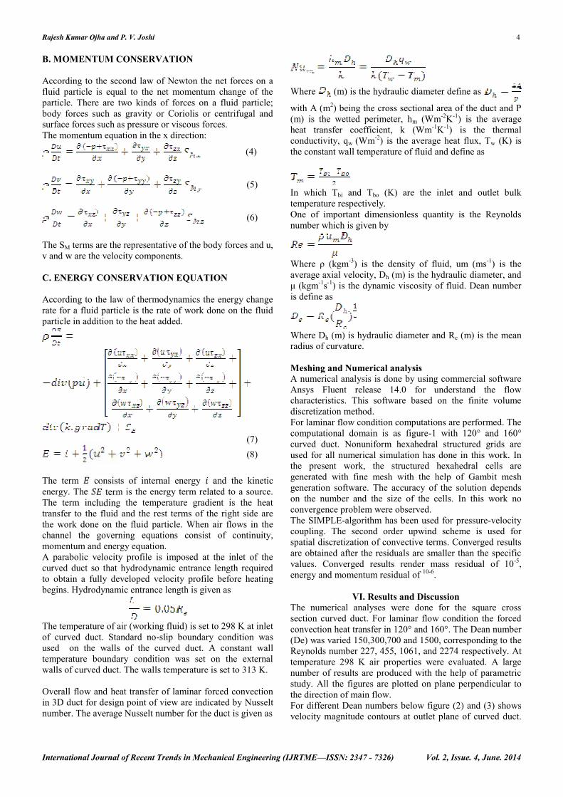
Meshing and Numerical analysisA numerical analysis is done by using commercial softwareAnsys Fluent release 14.0 for understand the flowcharacteristics. This software based on the finite volumediscretization method.For laminar flow condition computations are performed. Thecomputational domain is as figure-1 with 120° and 160°curved duct. Nonuniform hexahedral structured grids areused for all numerical simulation has done in this work. Inthe present work, the structured hexahedral cells aregenerated with fine mesh with the help of Gambit meshgeneration software. The accuracy of the solution dependson the number and the size of the cells. In this work noconvergence problem were observed.The SIMPLE-algorithm has been used for pressure-velocitycoupling. The second order upwind scheme is used forspatial discretization of convective terms. Converged resultsare obtained after the residuals are smaller than the specificvalues. Converged results render mass residual of 10-5,energy and momentum residual of 10-6.
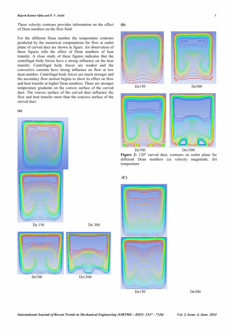
VI. Results and DiscussionThe numerical analyses were done for the square crosssection curved duct. For laminar flow condition the forcedconvection heat transfer in 120° and 160°. The Dean number(De) was varied 150,300,700 and 1500, corresponding to theReynolds number 227, 455, 1061, and 2274 respectively. Attemperature 298 K air properties were evaluated. A largenumber of results are produced with the help of parametricstudy. All the figures are plotted on plane perpendicular tothe direction of main flow.For different Dean numbers below figure (2) and (3) showsvelocity magnitude contours at outlet plane of curved duct.
Rajesh Kumar Ojha and P. V. Joshi 5
International Journal of Recent Trends in Mechanical Engineering (IJRTME—ISSN: 2347 - 7326) Vol. 2, Issue. 4, June. 2014
These velocity contours provides information on the effectof Dean numbers on the flow field.
For the different Dean number the temperature contourspredicted by the numerical computations for flow at outletplane of curved duct are shown in figure. An observation ofthese figures tells the effect of Dean numbers of heattransfer. A close study of these figures indicates that thecentrifugal body forces have a strong influence on the heattransfer. Centrifugal body forces are weaker and theconvective currents have strong influence on flow at lowdean number. Centrifugal body forces are much stronger andthe secondary flow motion begins to show its effect on flowand heat transfer at higher Dean numbers. There are strongertemperature gradients on the convex surface of the curvedduct. The convex surface of the curved duct influence theflow and heat transfer more than the concave surface of thecurved duct.
(a)
De 150 De 300
De700 De1500
(b)
De150 De300
De700 De1500Figure 2: 120° curved duct, contours on outlet plane fordifferent Dean numbers (a) velocity magnitude, (b)temperature
(C)
De150 De300
Rajesh Kumar Ojha and P. V. Joshi 6
International Journal of Recent Trends in Mechanical Engineering (IJRTME—ISSN: 2347 - 7326) Vol. 2, Issue. 4, June. 2014
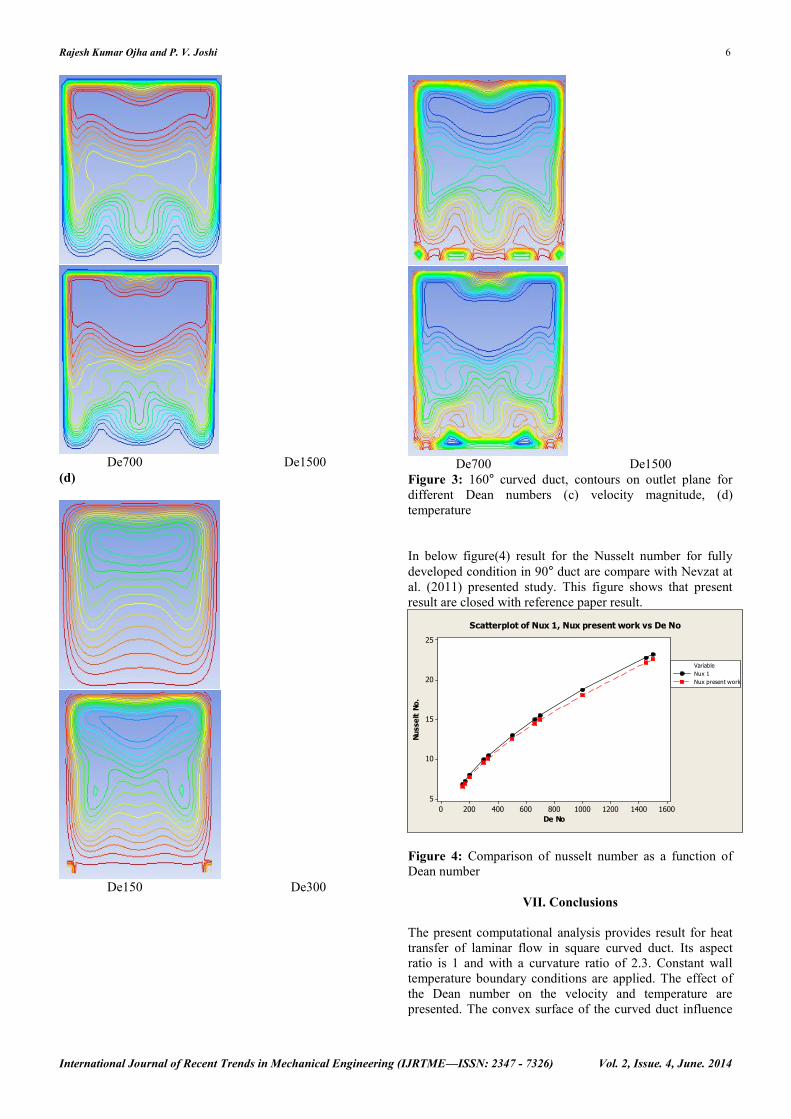
De700 De1500(d)
De150 De300
De700 De1500Figure 3: 160° curved duct, contours on outlet plane fordifferent Dean numbers (c) velocity magnitude, (d)temperature
In below figure(4) result for the Nusselt number for fullydeveloped condition in 90° duct are compare with Nevzat atal. (2011) presented study. This figure shows that presentresult are closed with reference paper result.
16001400120010008006004002000
25
20
15
10
5
De No
NusseltNo.
Nux 1Nux present work
Variable
Scatterplot of Nux 1, Nux present work vs De No
Figure 4: Comparison of nusselt number as a function ofDean number
VII. Conclusions
The present computational analysis provides result for heattransfer of laminar flow in square curved duct. Its aspectratio is 1 and with a curvature ratio of 2.3. Constant walltemperature boundary conditions are applied. The effect ofthe Dean number on the velocity and temperature arepresented. The convex surface of the curved duct influence
Rajesh Kumar Ojha and P. V. Joshi 7
International Journal of Recent Trends in Mechanical Engineering (IJRTME—ISSN: 2347 - 7326) Vol. 2, Issue. 4, June. 2014
the flow and heat transfer more than the concave surface ofthe curved duct.
REFERENCE1. Nevat Onur, Oguz Turgut, Kamil Arslan, three-
dimensional numerical analysis of forced convectionflow and heat transfer in a curved square duct, Kabul2010.
2. M. Raisee, H. Alemi, and H. Iacovides, Prediction ofdeveloping turbulent flow in 900-curved ducts usinglinear and non-linear low-Re k–ε models Departmentof Mechanical Engineering; Faculty of Engineering;University of Tehran; Tehran; Iran School ofMechanical; Aerospace and Civil Engineering;University of Manchester; Manchester; U.K.
3. M. Norouzi, M. H. Kayhani, M. R. H. Nobari, and M.Karimi Demneh Convective Heat Transfer ofViscoelastic Flow in a Curved Duct MechanicalEngineering Department, Shahrood University ofTechnology, P. O. 316, Post Code, 361 9995161,Shahrood, Iran Mechanical Engineering Department,Amir Kabir University of Technology, Tehran, IranMechanical Engineering Department, AzadUniversity, Karaj, Iran.
4. Benny Kuan , William, Chris solnordal, CFDsimulation and experimental validation of diluteparticylate turbulent flow in 900 duct bend, CSIROMinerals , clayton , victoria3168,Australia,2003
5. Haydar Kucuk Numerical analysis of entropygeneration in concentric curved annular ductsDepartment of Mechanical Engineering, GümüşhaneUniversity, 29000 Gümüşhane, Turkey. AcceptedMay 18, 2010.
6. K. Mohanarangam, W. Yang, H. J. Zhang and J. Y.TU effect of particles in a turbulent gas-particle flowwithin a 900 bend School of Aerospace, Mechanicaland Manufacturing Engineering, RMIT University,Victoria 3083, AUSTRALIA, CSIRO Minerals,Clayton, Victoria 3169, AUSTRALIA, China JiliangUniversity, Hangzhou, Zhejiang, P.R. CHINA. 9-11December 2009.
7. Jer-Huan Jang, Han-Chieh Chiu, and Wei-Mon Yanwall transpiration effects on developing mixedconvection heat transfer in inclined rectangular ductsDepartment of Mechanical Engineering, Ming ChiUniversity of Technology, Taishan, Taipei County,Taiwan 243, R.O.C. Department of MechanicalEngineering, Technology and Science Institute ofNorthern Taiwan, Pei-To, Taipei, Taiwan 112,R.O.C. accepted 06/08/09.
8. Tony W. H. Sheu, S. F. Tsai Vortical flow topologyin a curved duct with 900 bend Dept. of EngineeringScience and Ocean Engineering, National TaiwanUniversity, No. 1, Sec. 4, Roosevelt Rd., Taipei,Taiwan 106, R.O.C. Dept. of Marine Engineering,National Taiwan Ocean University, No. 2, Pei-NingRd., Keelng, Taiwan 202, R. O. C. August 21-23,2006.
9. M. H. kayhani f. talebi, m. asadi, Numerical Analysisof Mixed Convection Heat Transfer (Forced & Free)of Viscoelastic Fluid in a Square Channel for
Laminar and Fully Developed Flow, Department ofMechanical Engineering Shahrood University ofTechnology Shahrood IRAN Nov.2006.
10. Hosselnall soltanipour, Parisa choupani and Irajmirzaee, Numerical analysis of heat transferenhanchment with the use of γ=Al2O3 /waternanofluid with ribs in a curved duct,Department ofmechanical engineering, Urmia university oftechnology, Urmia ,Iran,2012
11. B. T. Kuan CFD simulation of dilute gas-solid twophase flow with different solid size distribution in acurved 90° duct bend, Cooperative research centerfor power from lignite , division of minerals CSIRO,Clayton ,Australia,2005.
12. Kazimierz Rup, Lukasz Malinowski, Piotr Sarna,measurement of flow rate in square-sectionedCracow University of Technology, Faculty ofMechanical Engineering, Kraków, Poland 2011.
13. Quamr u l H . Mazumder, CFD Analysis of the Effectof Elbow Radius on Pressure Drop in MultiphaseFlow, Mechanical Engineering, University ofMichigan-Flint, Flint, M I 48502, USA, September2012
14. Kyung Hwan Kim, Jin Gi Paeng and Young HwanYoon, Comparison between numerical computationsand measurements by LDV for fluid flow inrectangular duct systems Department of MechanicalEngineering, Changwon National University,Springer 2008.
15. Quamrul H. Mazumder, CFD Analysis of Single andMultiphase Flow Characteristics in Elbow,Mechanical Engineering, University of Michigan-Flint, Flint, USA, March 5, 2012.
Rajesh Kumar OjhaBE in Mechanical Engg.Asst. Professor, CSIT, Deptt. of Mech.Engg.6 Year of Teaching Experiencee-mail id: [email protected]